MEBS6008 Environmental Services II - ibse.hk
60
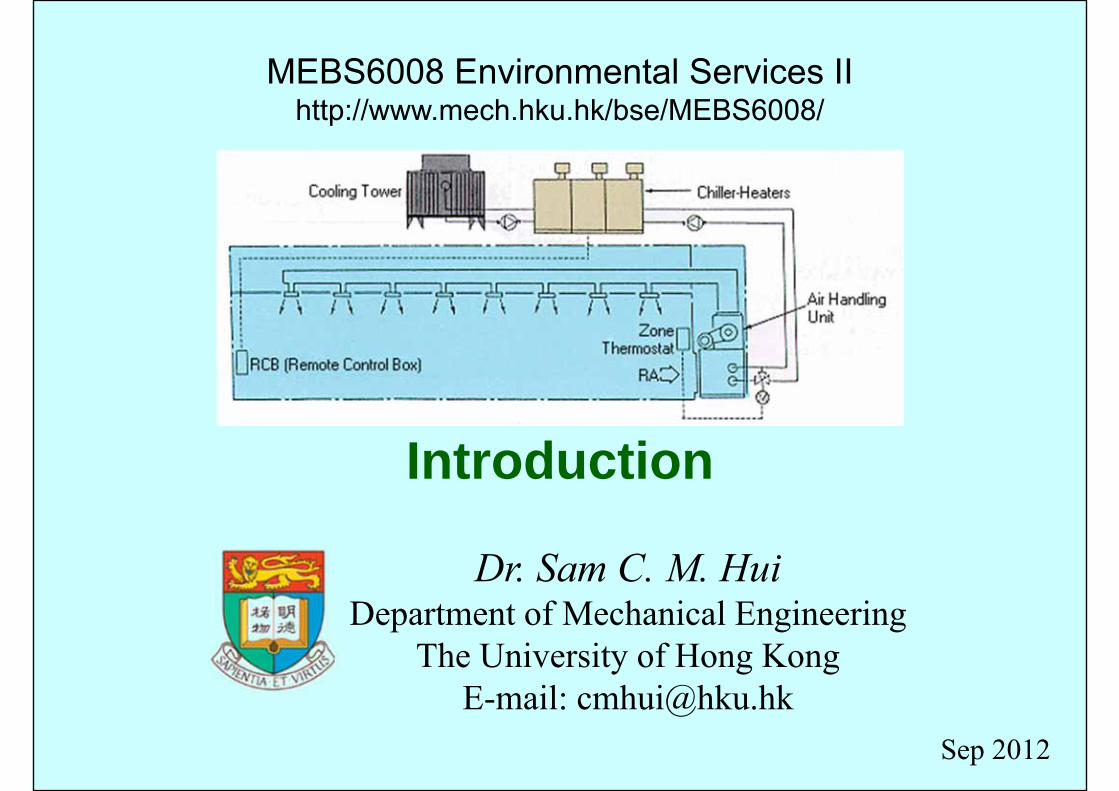
Introduction Dr. Sam C. M. Hui Department of Mechanical Engineering The University of Hong Kong E-mail: [email protected] MEBS6008 Environmental Services II http://www.mech.hku.hk/bse/MEBS6008/ Sep 2012
Transcript of MEBS6008 Environmental Services II - ibse.hk
Introduction
Dr. Sam C. M. HuiDepartment of Mechanical Engineering
The University of Hong KongE-mail: [email protected]
MEBS6008 Environmental Services IIhttp://www.mech.hku.hk/bse/MEBS6008/
Sep 2012

Background
• MEBS6008 Environmental Services II• Educational Objectives:
• To introduce students to the important systems and applications of environmental services for more detailed study.
• To enable students to design appropriate heating, ventilating, air-conditioning and refrigerating (HVAC&R) systems and evaluate their characteristics and performance.
Background
• MEBS6008 Environmental Services II• Learning Outcomes:
• To describe the basic principles and characteristics of HVAC systems and components.
• To develop skills for design of HVAC&R systems and evaluation of their characteristics and performance.
• Assessment: 100% by examination (2 hours)
Background
• Two related courses:• MEBS6006 Environmental services I
• Basic principles of HVACR• Practical design skills
• MEBS6008 Environmental services II• System characteristics and operation• Analysis and design strategies
Background
• Study topics of MEBS6008:• Fluid Network Analysis• Fans and Pumps• Space Air Diffusion• Heat Rejection & Sea Water Cooling• Thermal Storage Systems• Heat Pumps & Heat Recovery Systems• Noise & Vibration Control
Dr. Sam C. M. Hui
Dr. Benjamin P. L. Ho
Background
• Recommended references:• ASHRAE, 2009. ASHRAE Fundamentals Handbook 2009,
SI edition, American Society of Heating, Refrigerating, and Air-Conditioning Engineers, Atlanta, GA. [ebook via Knovel][ASHRAE catalog via Techstreet]
• ASHRAE, 2010. ASHRAE Refrigeration Handbook 2010, SI edition, American Society of Heating, Refrigerating, and Air-Conditioning Engineers, Atlanta, GA. [ASHRAE catalog via Techstreet][ebook via Knovel (IP edition)]
• Wang, S. K., 2001. Handbook of Air Conditioning and Refrigeration, 2nd ed., McGraw-Hill, New York. [697.93 W24 h]
Fluid Network Analysis I
Dr. Sam C. M. HuiDepartment of Mechanical Engineering
The University of Hong KongE-mail: [email protected]
MEBS6008 Environmental Services IIhttp://www.mech.hku.hk/bse/MEBS6008/
Sep 2012

Contents
• Fluid Properties
• Fluid Dynamics
• Basic Flow Processes
• Flow Analysis
Fluid Properties
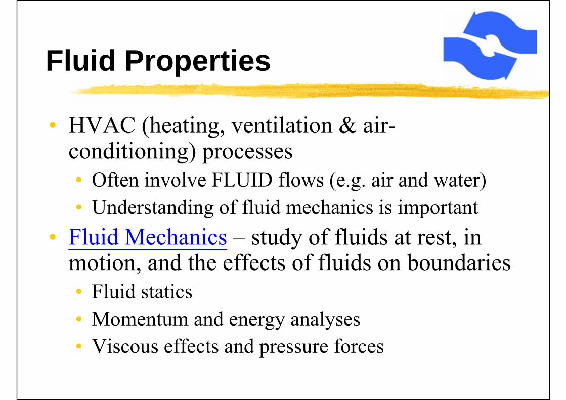
• HVAC (heating, ventilation & air-conditioning) processes• Often involve FLUID flows (e.g. air and water)• Understanding of fluid mechanics is important
• Fluid Mechanics – study of fluids at rest, in motion, and the effects of fluids on boundaries• Fluid statics• Momentum and energy analyses• Viscous effects and pressure forces
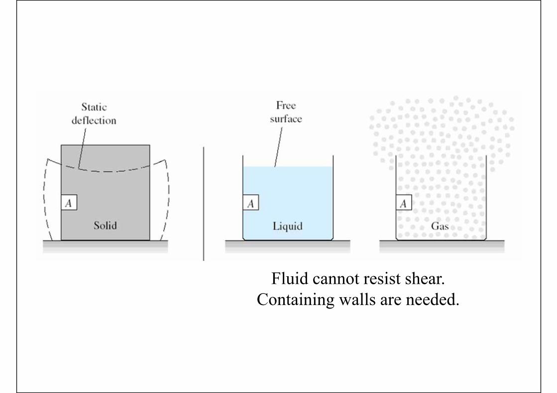
Fluid cannot resist shear.Containing walls are needed.
Fluid Properties
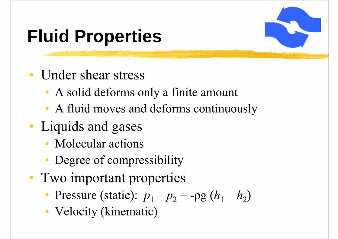
• Under shear stress• A solid deforms only a finite amount• A fluid moves and deforms continuously
• Liquids and gases• Molecular actions• Degree of compressibility
• Two important properties• Pressure (static): p1 – p2 = -ρg (h1 – h2)• Velocity (kinematic)
Fluid Properties
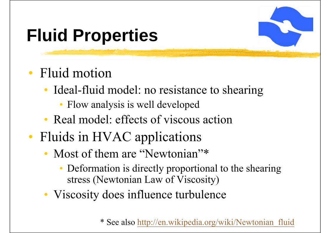
• Fluid motion• Ideal-fluid model: no resistance to shearing
• Flow analysis is well developed• Real model: effects of viscous action
• Fluids in HVAC applications• Most of them are “Newtonian”*
• Deformation is directly proportional to the shearing stress (Newtonian Law of Viscosity)
• Viscosity does influence turbulence
* See also http://en.wikipedia.org/wiki/Newtonian_fluid
Fluid Properties
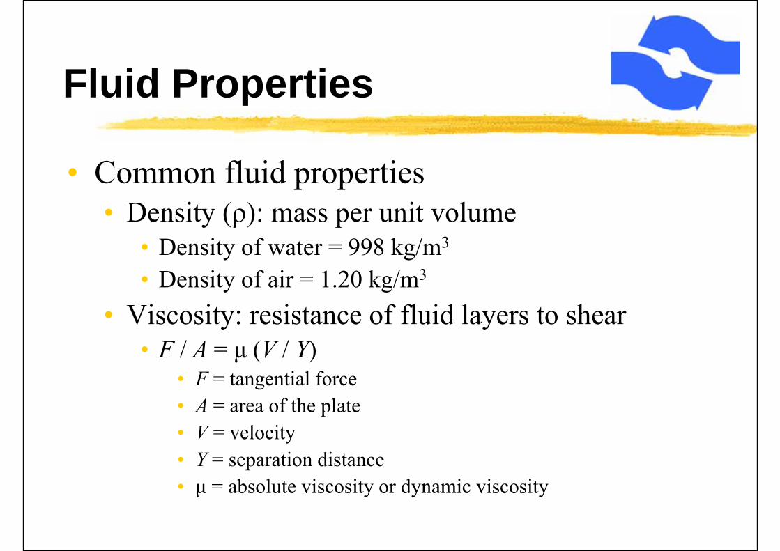
• Common fluid properties• Density (ρ): mass per unit volume
• Density of water = 998 kg/m3
• Density of air = 1.20 kg/m3
• Viscosity: resistance of fluid layers to shear• F / A = μ (V / Y)
• F = tangential force• A = area of the plate• V = velocity• Y = separation distance• μ = absolute viscosity or dynamic viscosity
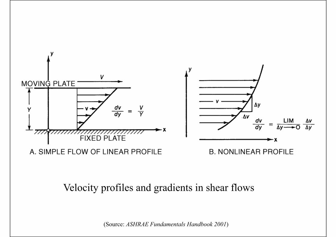
Velocity profiles and gradients in shear flows
(Source: ASHRAE Fundamentals Handbook 2001)
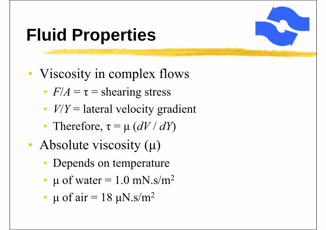
Fluid Properties
• Viscosity in complex flows• F/A = τ = shearing stress• V/Y = lateral velocity gradient• Therefore, τ = μ (dV / dY)
• Absolute viscosity (μ)• Depends on temperature• μ of water = 1.0 mN.s/m2
• μ of air = 18 μN.s/m2
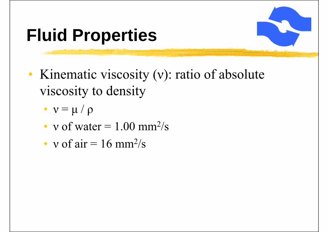
Fluid Properties
• Kinematic viscosity (ν): ratio of absolute viscosity to density• ν = μ / ρ• ν of water = 1.00 mm2/s• ν of air = 16 mm2/s

Fluid Dynamics
• Physical laws for homogenous, constant-property, incompressible fluids
• Continuity: conservation of matter• ∫(density x velocity) dA = constant• For constant cross-sectional area,
• Mass flow rate = ρ V A = constant
• When flow is incompressible, ρ is constant, then• Volume flow rate = V A = constant
Fluid Dynamics
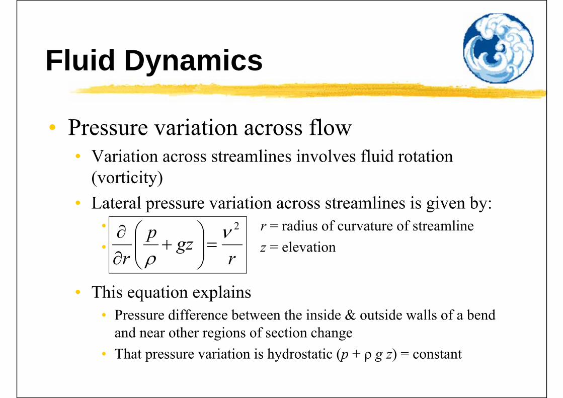
• Pressure variation across flow• Variation across streamlines involves fluid rotation
(vorticity)• Lateral pressure variation across streamlines is given by:
• r = radius of curvature of streamline• z = elevation
• This equation explains• Pressure difference between the inside & outside walls of a bend
and near other regions of section change• That pressure variation is hydrostatic (p + ρ g z) = constant
rgzp
r
2
Fluid Dynamics
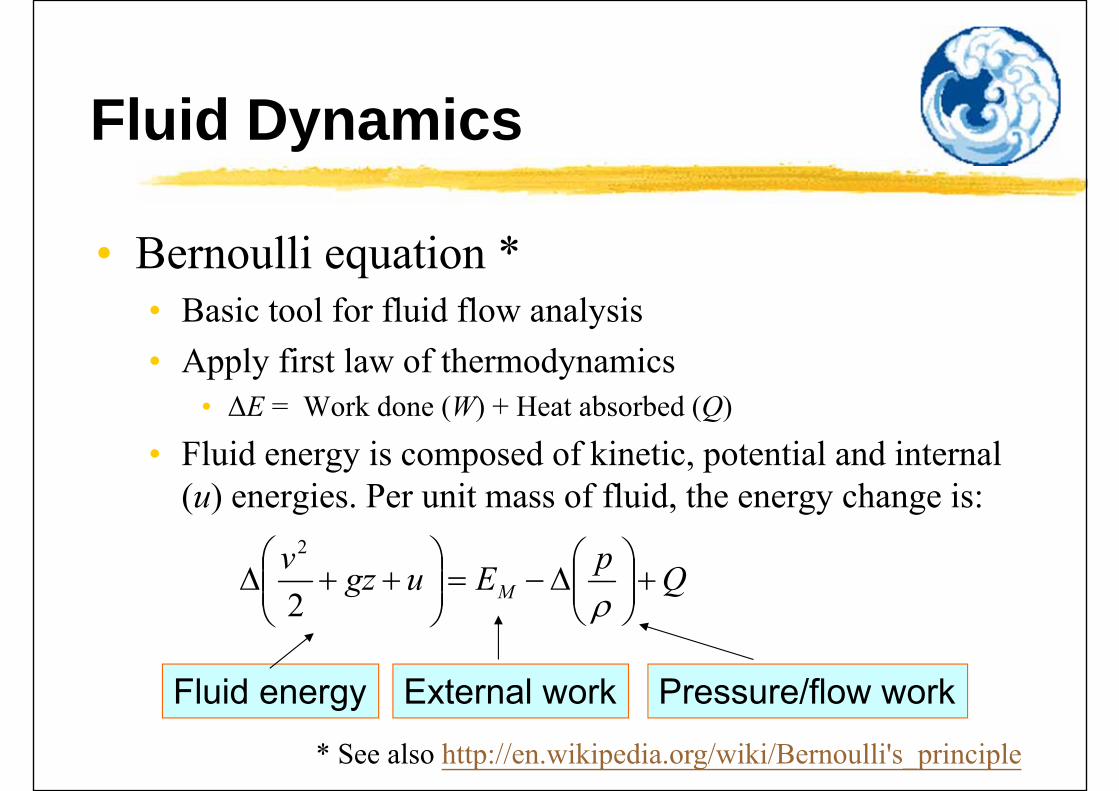
• Bernoulli equation *• Basic tool for fluid flow analysis• Apply first law of thermodynamics
• ΔE = Work done (W) + Heat absorbed (Q)
• Fluid energy is composed of kinetic, potential and internal (u) energies. Per unit mass of fluid, the energy change is:
QpEugzvM
2
2
Fluid energy External work Pressure/flow work
* See also http://en.wikipedia.org/wiki/Bernoulli's_principle
Fluid Dynamics
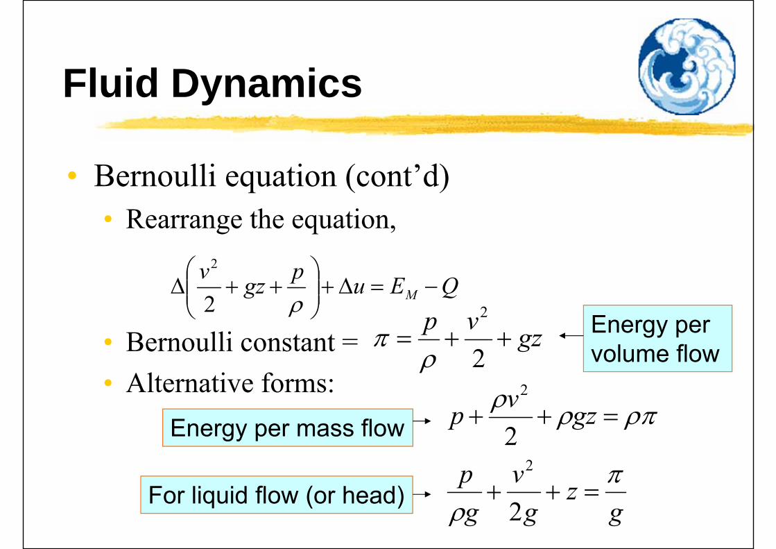
• Bernoulli equation (cont’d)• Rearrange the equation,
• Bernoulli constant = • Alternative forms:
QEupgzvM
2
2
gzvp
2
2
gz
gv
gp
gzvp
2
22
2
Energy per volume flow
Energy per mass flow
For liquid flow (or head)
Fluid Dynamics
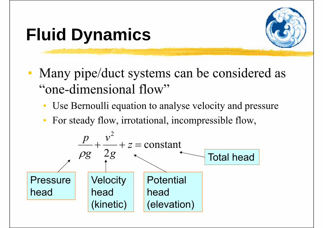
• Many pipe/duct systems can be considered as “one-dimensional flow”• Use Bernoulli equation to analyse velocity and pressure• For steady flow, irrotational, incompressible flow,
constant2
2
zg
vgp
Pressure head
Velocity head(kinetic)
Potential head (elevation)
Total head

Fluid Dynamics
• If the section-average velocity (V) is used, the kinetic energy term of the Bernoulli constant (v2/2) is expressed as (αV 2/2),• where α = kinetic energy factor (ratio of true
kinetic energy of the velocity profile to that of the mean flow velocity)
• For laminar flow in a wide rectangular channel, α= 1.54; for a pipe, α = 2.0
Fluid Dynamics
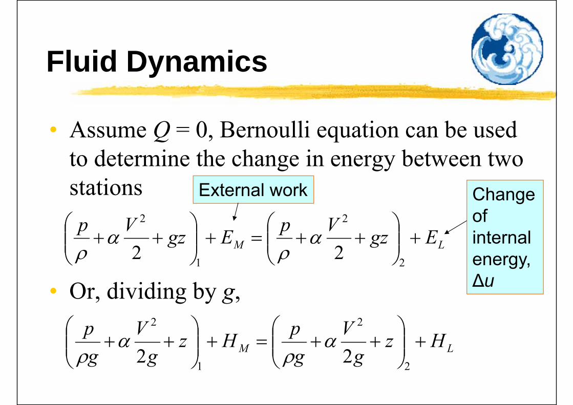
• Assume Q = 0, Bernoulli equation can be used to determine the change in energy between two stations
• Or, dividing by g,
LM EgzVpEgzVp
2
2
1
2
22
External work Change of internal energy, ∆u
LM Hzg
VgpHz
gV
gp
2
2
1
2
22
Fluid Dynamics
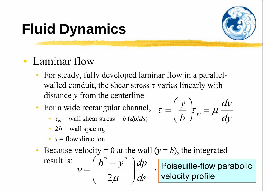
• Laminar flow• For steady, fully developed laminar flow in a parallel-
walled conduit, the shear stress τ varies linearly with distance y from the centerline
• For a wide rectangular channel,• τw = wall shear stress = b (dp/ds)• 2b = wall spacing• s = flow direction
• Because velocity = 0 at the wall (y = b), the integrated result is:
dydv
by
w
dsdpybv
2
22Poiseuille-flow parabolic velocity profile
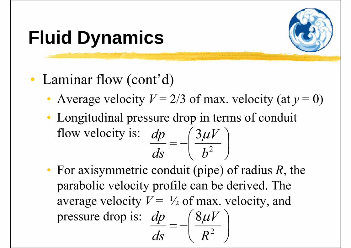
Fluid Dynamics
• Laminar flow (cont’d)• Average velocity V = 2/3 of max. velocity (at y = 0)• Longitudinal pressure drop in terms of conduit
flow velocity is:
• For axisymmetric conduit (pipe) of radius R, the parabolic velocity profile can be derived. The average velocity V = ½ of max. velocity, and pressure drop is:
2
3b
Vdsdp
2
8R
Vdsdp


Fluid Dynamics
• Turbulence• Random fluctuations of flow (velocity & pressure)
• Without any order or periodicity
• Can be quantified by statistical factors• “Strength of turbulence” is characterized by the root-mean-square
of the instantaneous velocity variation about the mean velocity
• Effect of turbulence• Cause the fluid to diffuse momentum, heat and mass very rapidly
across the flow
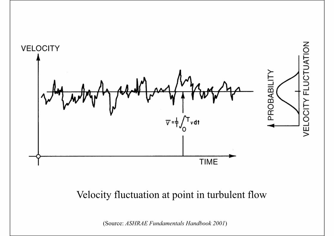
Velocity fluctuation at point in turbulent flow
(Source: ASHRAE Fundamentals Handbook 2001)
Fluid Dynamics
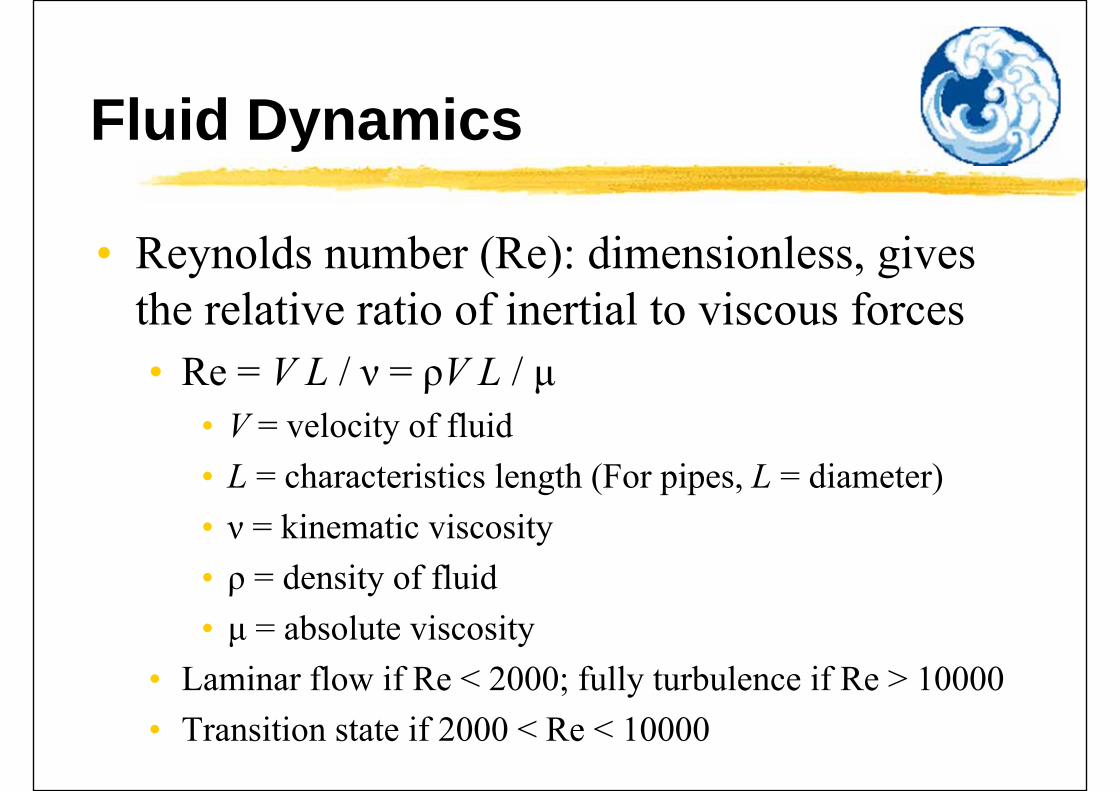
• Reynolds number (Re): dimensionless, gives the relative ratio of inertial to viscous forces• Re = V L / ν = ρV L / μ
• V = velocity of fluid• L = characteristics length (For pipes, L = diameter)• ν = kinematic viscosity• ρ = density of fluid• μ = absolute viscosity
• Laminar flow if Re < 2000; fully turbulence if Re > 10000• Transition state if 2000 < Re < 10000
Fluid Flow Visualisation
• Video presentation• Fluid Flow [video, 24 min.], show how a fluid
flows over a solid body• Boundary layer, Vorticity, Drag, Unsteady forces,
Wave motions
• YouTube:• Slow flow past cylinder - experimental (0:30), http://youtu.be/gbDscDSUAg4• Slightly faster flow past cylinder - experimental (0:12),
http://youtu.be/vQHXIHpvcvU• Flow past cylinder: Karman vortex Street - experimental (0:10),
http://youtu.be/CB2aWiesq0g• Experimental flow separation (0:37), http://youtu.be/Vjk9Ux2COx0

Basic Flow Processes
• Wall friction• At the boundary of real-fluid flow, the relative
tangential velocity at fluid surface is zero• High shear stress near the wall boundary• Slowing down of adjacent fluid layers
• Velocity profiles near a wall• Laminar and turbulent flow differ significantly• Pipe factor = ratio of average to max. (centreline)
velocity
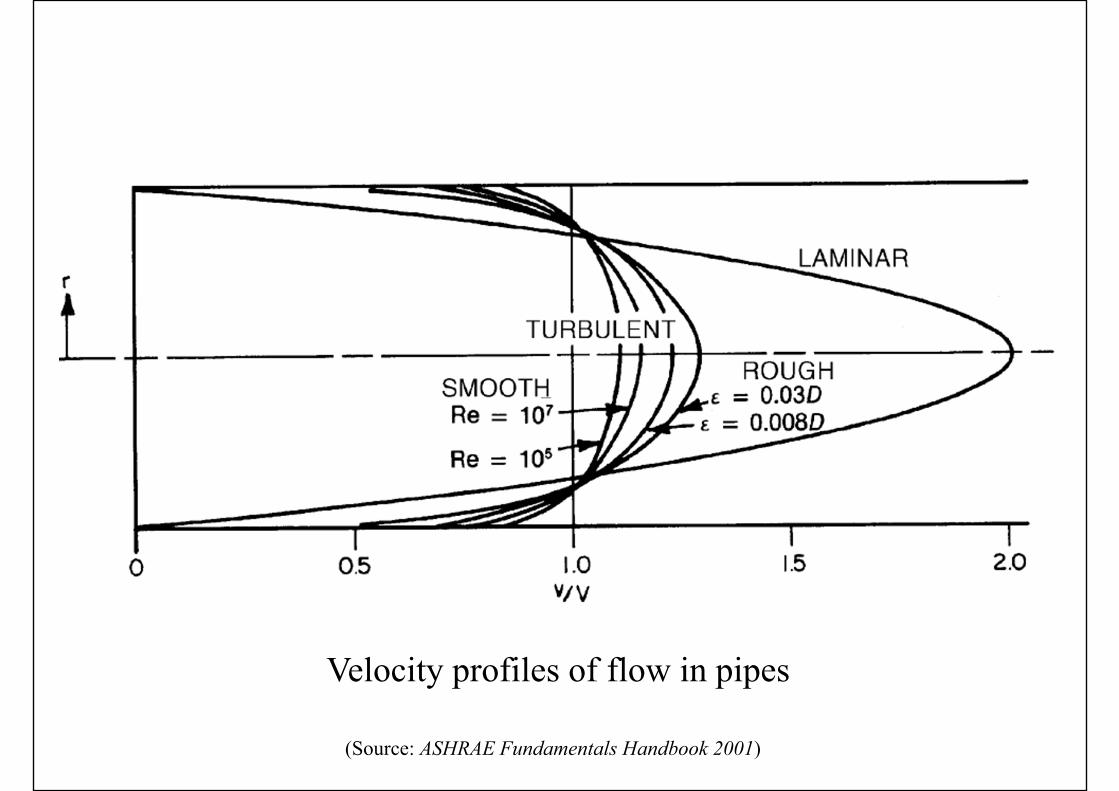
Velocity profiles of flow in pipes
(Source: ASHRAE Fundamentals Handbook 2001)
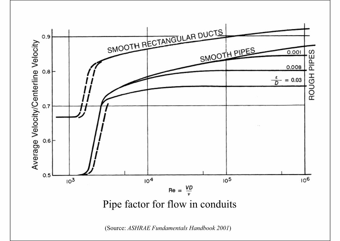
Pipe factor for flow in conduits
(Source: ASHRAE Fundamentals Handbook 2001)
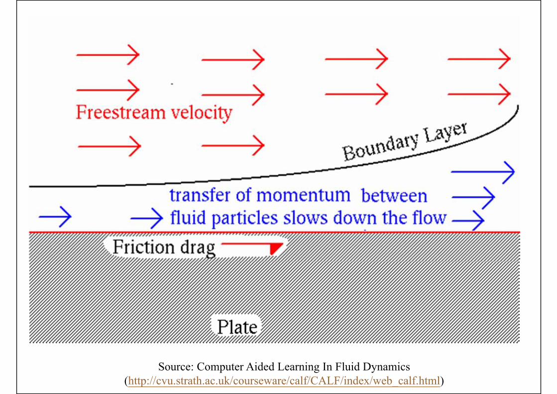
Source: Computer Aided Learning In Fluid Dynamics(http://cvu.strath.ac.uk/courseware/calf/CALF/index/web_calf.html)
Basic Flow Processes
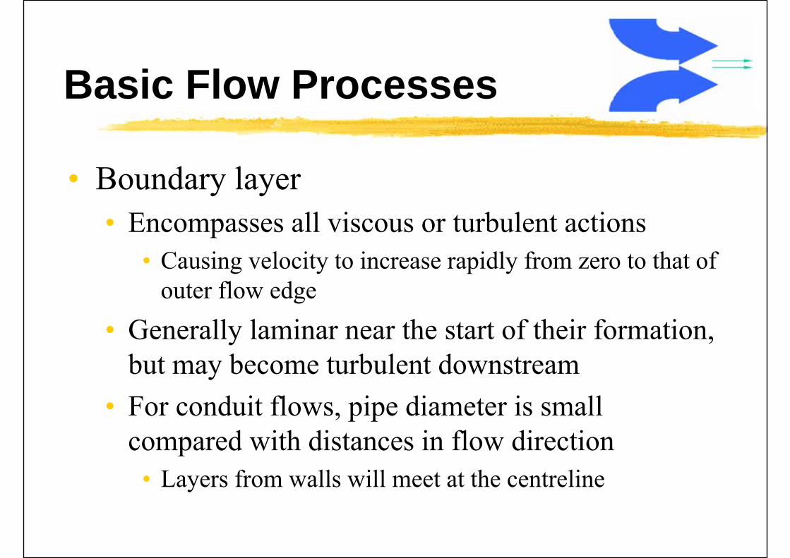
• Boundary layer• Encompasses all viscous or turbulent actions
• Causing velocity to increase rapidly from zero to that of outer flow edge
• Generally laminar near the start of their formation, but may become turbulent downstream
• For conduit flows, pipe diameter is small compared with distances in flow direction
• Layers from walls will meet at the centreline
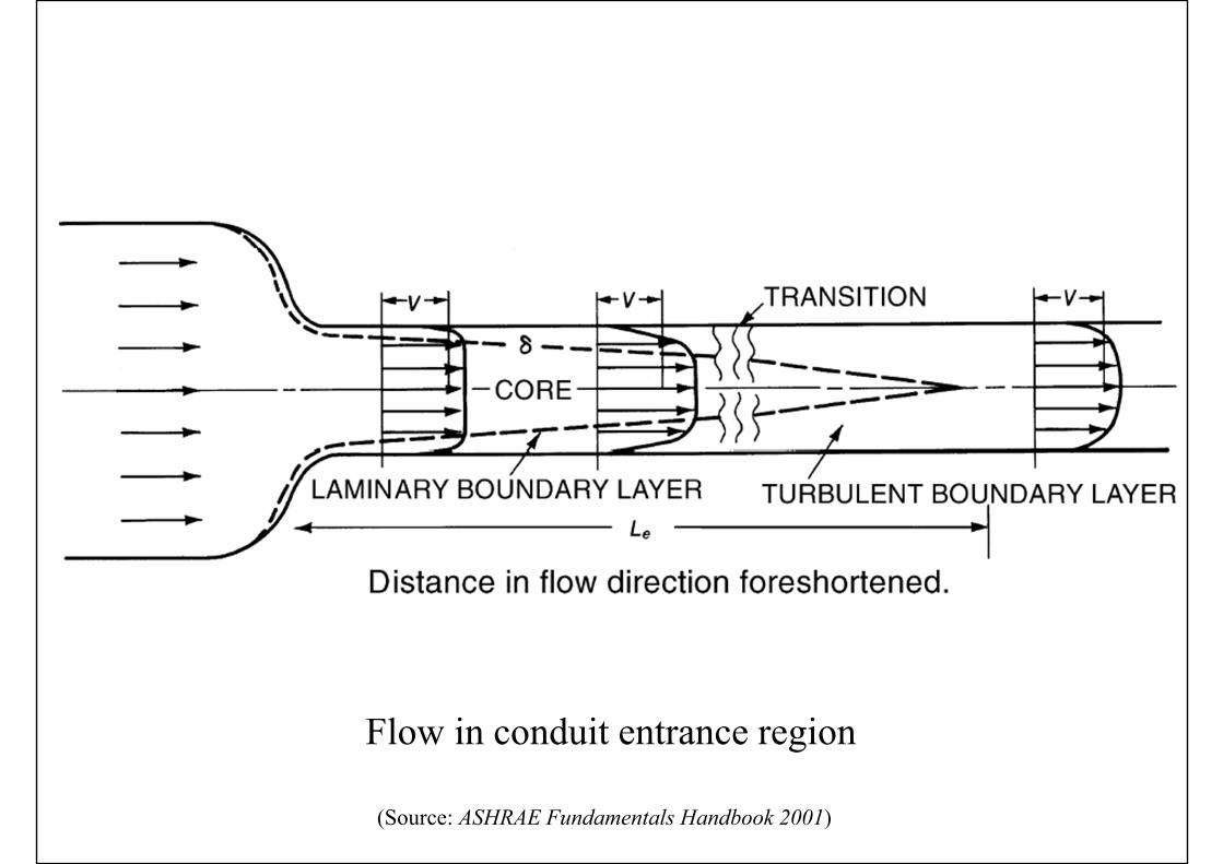
Flow in conduit entrance region
(Source: ASHRAE Fundamentals Handbook 2001)
Basic Flow Processes
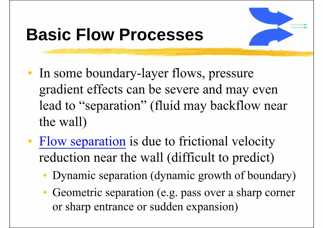
• In some boundary-layer flows, pressure gradient effects can be severe and may even lead to “separation” (fluid may backflow near the wall)
• Flow separation is due to frictional velocity reduction near the wall (difficult to predict)• Dynamic separation (dynamic growth of boundary)• Geometric separation (e.g. pass over a sharp corner
or sharp entrance or sudden expansion)
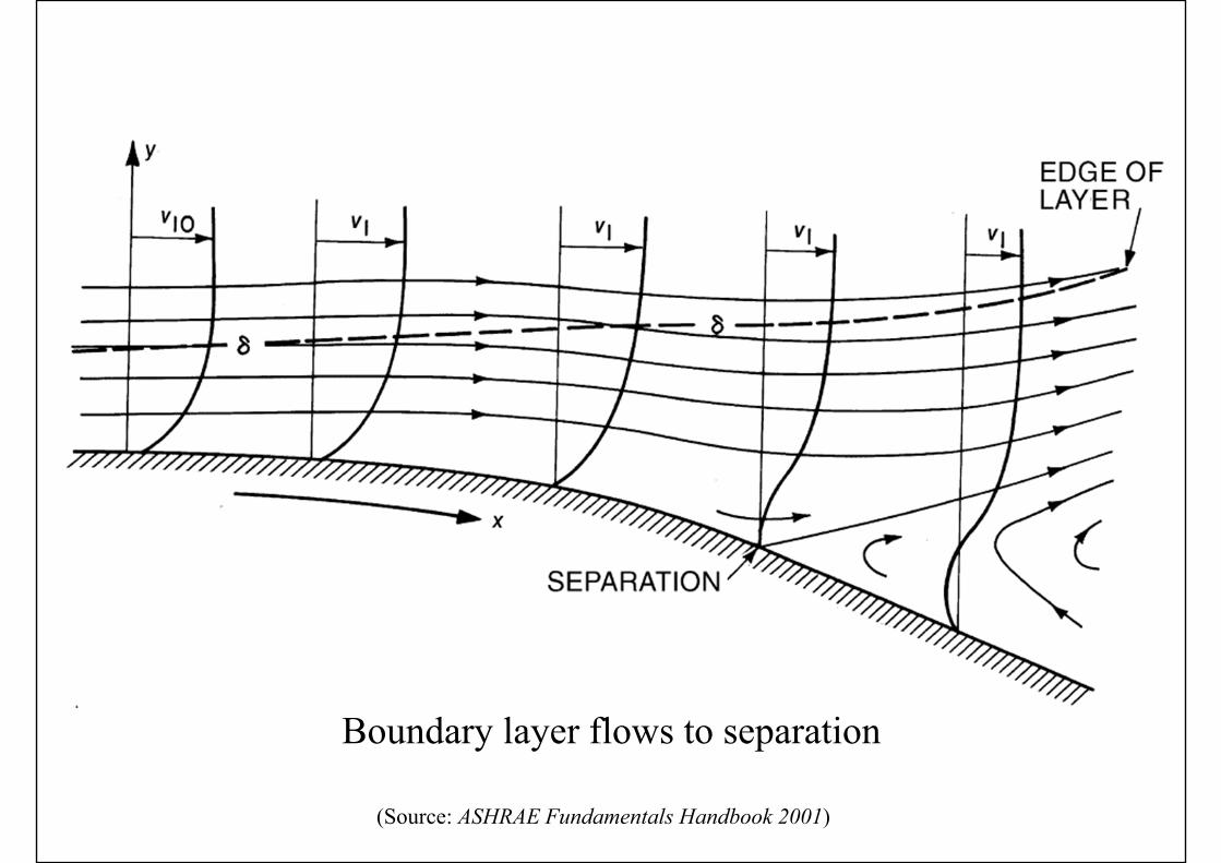
Boundary layer flows to separation
(Source: ASHRAE Fundamentals Handbook 2001)
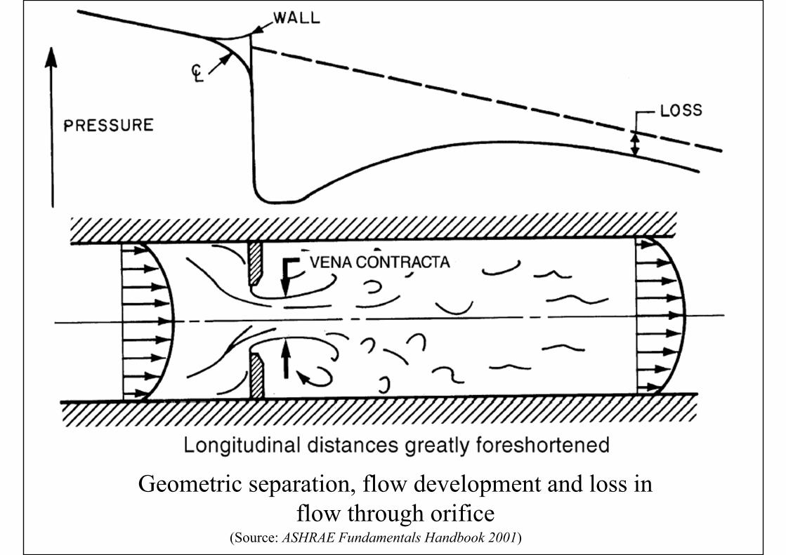
Geometric separation, flow development and loss inflow through orifice
(Source: ASHRAE Fundamentals Handbook 2001)
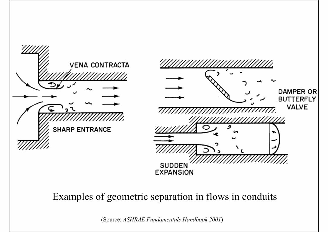
Examples of geometric separation in flows in conduits
(Source: ASHRAE Fundamentals Handbook 2001)
Basic Flow Processes
• Flow separation in diffuser• To expand a flow efficiently, the device shall be
designed with gradual contours, a diffuser, or a rounded entrance
• To control separation• May use splitters to divide the diffuser into smaller
divisions less likely to have separations• May bleed some low-velocity fluid near the wall
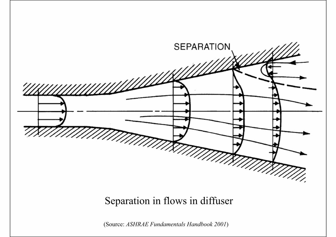
Separation in flows in diffuser
(Source: ASHRAE Fundamentals Handbook 2001)
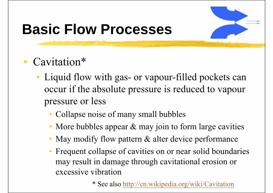
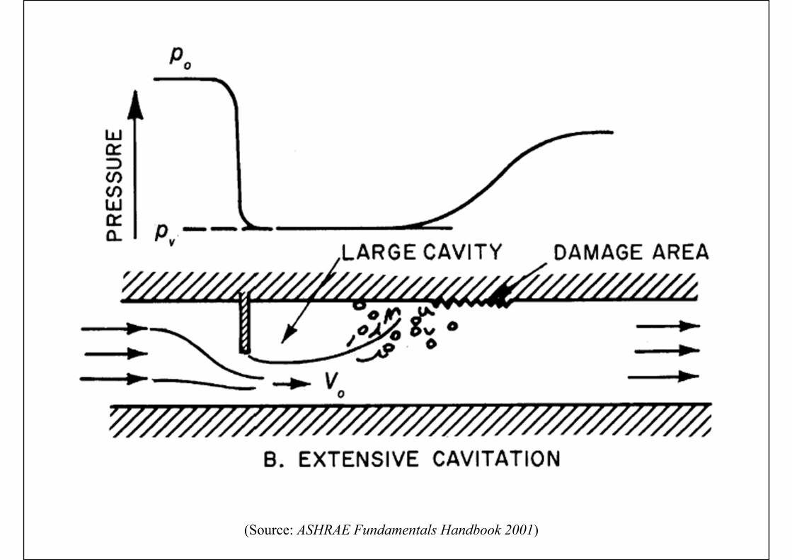
Basic Flow Processes
• Cavitation*• Liquid flow with gas- or vapour-filled pockets can
occur if the absolute pressure is reduced to vapourpressure or less
• Collapse noise of many small bubbles• More bubbles appear & may join to form large cavities• May modify flow pattern & alter device performance• Frequent collapse of cavities on or near solid boundaries
may result in damage through cavitational erosion or excessive vibration
* See also http://en.wikipedia.org/wiki/Cavitation

(Source: ASHRAE Fundamentals Handbook 2001)
(Source: ASHRAE Fundamentals Handbook 2001)
Basic Flow Processes
• Methods to avoid cavitation• 1. Operate the device at high enough pressure• 2. Change the flow• 3. Device is built to withstand the cavitation
effects (e.g. by surface coating)• 4. Design surface contours to delay the advent of
cavitation
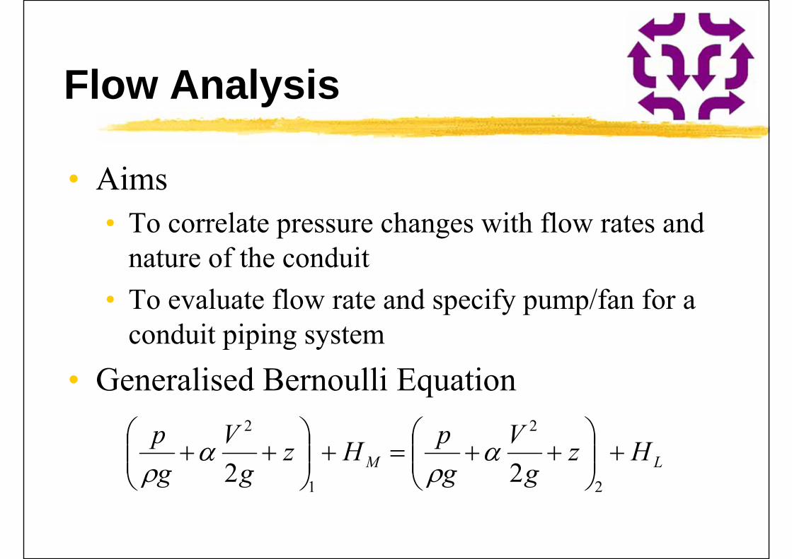
Flow Analysis
• Aims• To correlate pressure changes with flow rates and
nature of the conduit• To evaluate flow rate and specify pump/fan for a
conduit piping system• Generalised Bernoulli Equation
LM Hzg
VgpHz
gV
gp
2
2
1
2
22
Flow Analysis
• Worked Example:• Specify the fan to produce an isothermal airflow of
200 L/s through the ducting system. Accounting for intake and fitting losses, the equivalent conduit lengths are 18 and 50 m and the flow is isothermal. The pressure at the inlet (station 1) and following the discharge (station 4), where the velocity is zero, are the same. Friction losses HL are evaluated as 7.5 m of air between stations 1 and 2, and 72.3 m between stations 3 and 4.
(Source: ASHRAE Fundamentals Handbook 2001)
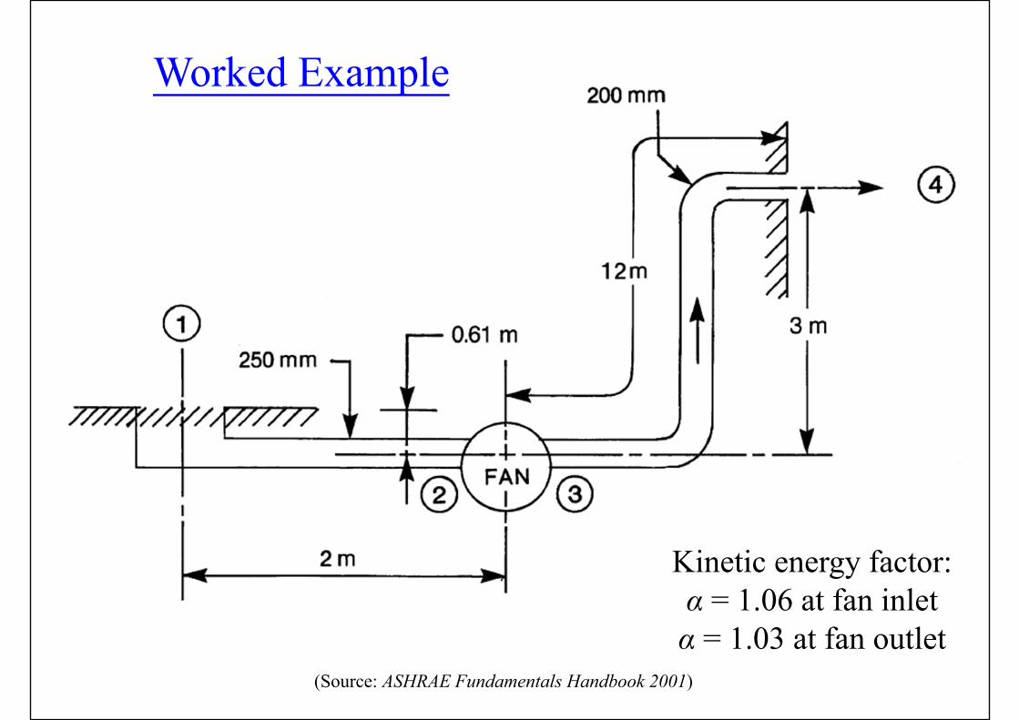
Worked Example
Kinetic energy factor:α = 1.06 at fan inletα = 1.03 at fan outlet
Flow Analysis
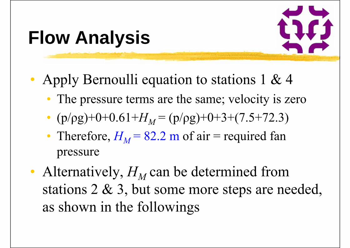
• Apply Bernoulli equation to stations 1 & 4• The pressure terms are the same; velocity is zero• (p/ρg)+0+0.61+HM = (p/ρg)+0+3+(7.5+72.3)• Therefore, HM = 82.2 m of air = required fan
pressure• Alternatively, HM can be determined from
stations 2 & 3, but some more steps are needed, as shown in the followings
Flow Analysis
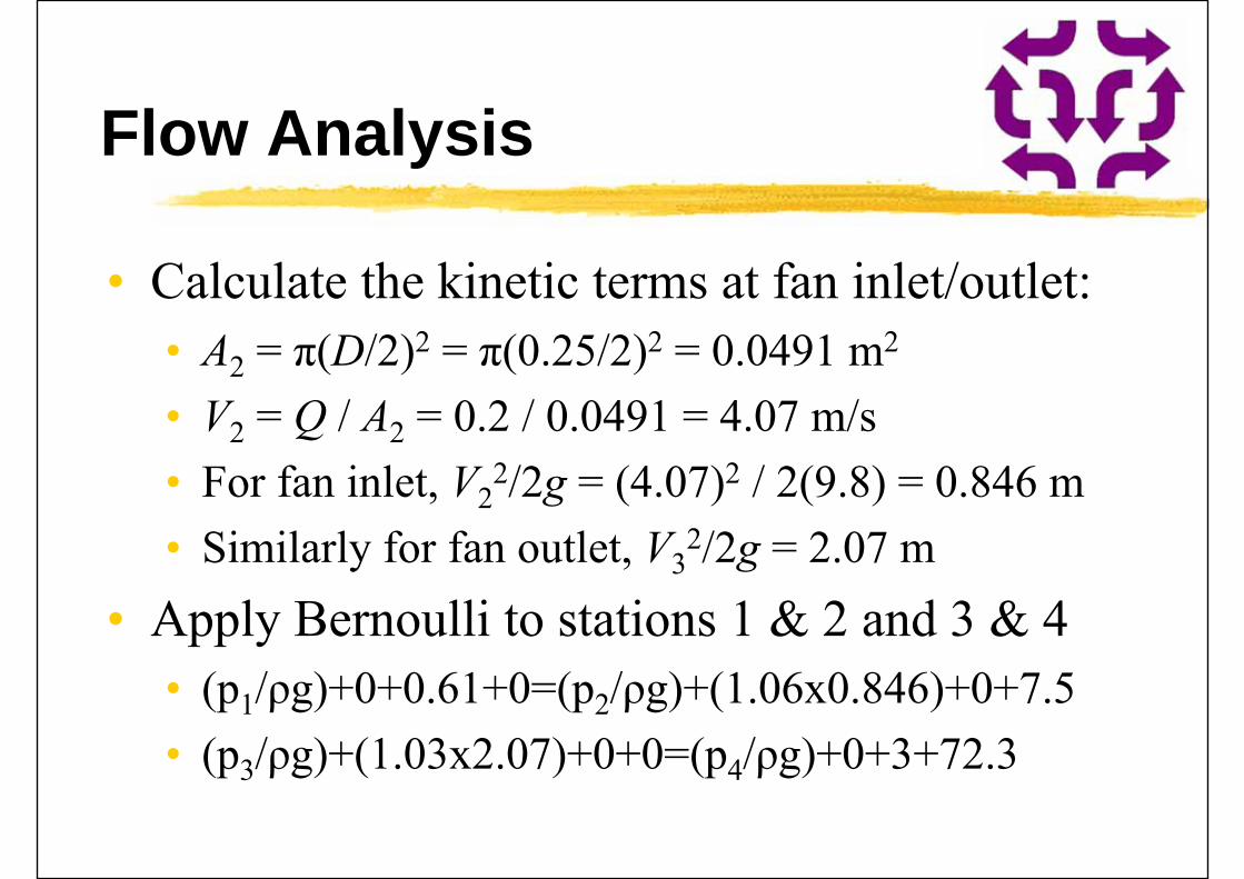
• Calculate the kinetic terms at fan inlet/outlet:• A2 = π(D/2)2 = π(0.25/2)2 = 0.0491 m2
• V2 = Q / A2 = 0.2 / 0.0491 = 4.07 m/s• For fan inlet, V2
2/2g = (4.07)2 / 2(9.8) = 0.846 m• Similarly for fan outlet, V3
2/2g = 2.07 m• Apply Bernoulli to stations 1 & 2 and 3 & 4
• (p1/ρg)+0+0.61+0=(p2/ρg)+(1.06x0.846)+0+7.5• (p3/ρg)+(1.03x2.07)+0+0=(p4/ρg)+0+3+72.3
Flow Analysis
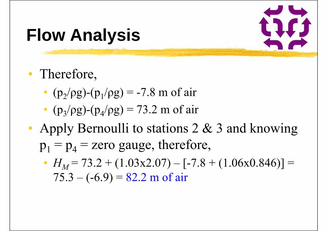
• Therefore,• (p2/ρg)-(p1/ρg) = -7.8 m of air• (p3/ρg)-(p4/ρg) = 73.2 m of air
• Apply Bernoulli to stations 2 & 3 and knowing p1 = p4 = zero gauge, therefore,• HM = 73.2 + (1.03x2.07) – [-7.8 + (1.06x0.846)] =
75.3 – (-6.9) = 82.2 m of air
Flow Analysis
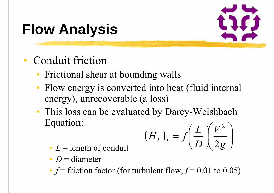
• Conduit friction• Frictional shear at bounding walls• Flow energy is converted into heat (fluid internal
energy), unrecoverable (a loss)• This loss can be evaluated by Darcy-Weishbach
Equation:
• L = length of conduit• D = diameter• f = friction factor (for turbulent flow, f = 0.01 to 0.05)
gV
DLfH fL 2
2
Flow Analysis
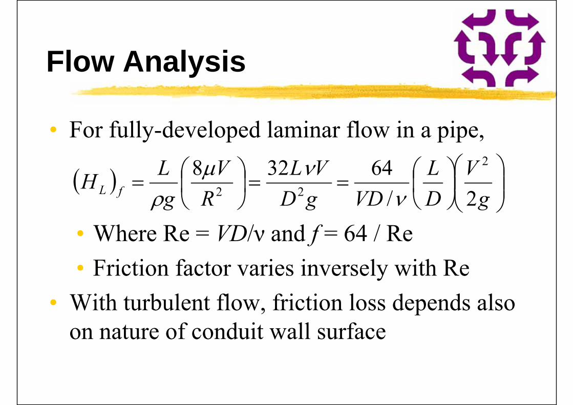
• For fully-developed laminar flow in a pipe,
• Where Re = VD/ν and f = 64 / Re• Friction factor varies inversely with Re
• With turbulent flow, friction loss depends also on nature of conduit wall surface
gV
DL
VDgDVL
RV
gLH fL 2/
64328 2
22
Flow Analysis
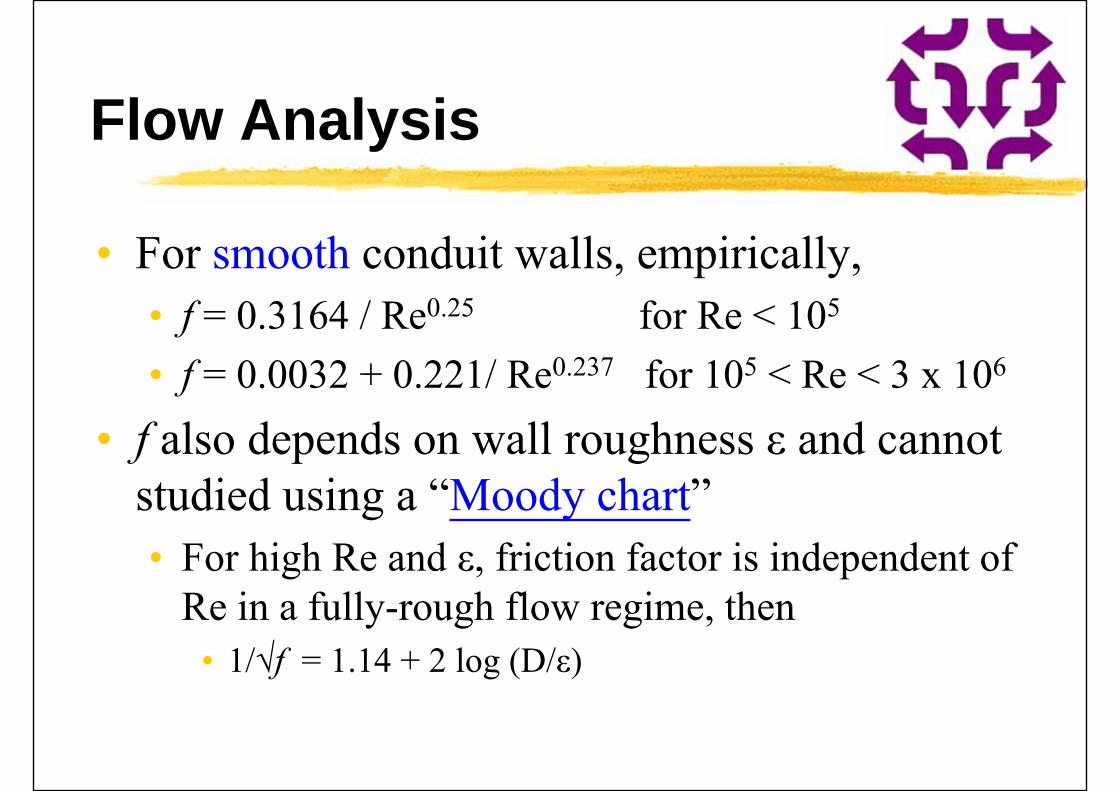
• For smooth conduit walls, empirically,• f = 0.3164 / Re0.25 for Re < 105
• f = 0.0032 + 0.221/ Re0.237 for 105 < Re < 3 x 10⁶
• f also depends on wall roughness ε and cannot studied using a “Moody chart”• For high Re and ε, friction factor is independent of
Re in a fully-rough flow regime, then• 1/√f = 1.14 + 2 log (D/ε)

(Source: ASHRAE Fundamentals Handbook 2005)
Flow Analysis
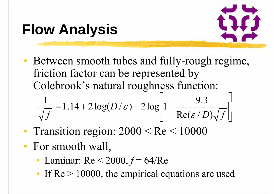
• Between smooth tubes and fully-rough regime, friction factor can be represented by Colebrook’s natural roughness function:
• Transition region: 2000 < Re < 10000• For smooth wall,
• Laminar: Re < 2000, f = 64/Re• If Re > 10000, the empirical equations are used
fDD
f )/Re(3.91log2)/log(214.11
Flow Analysis
• For rough walls, Moody chart and Colebrook function are used to assess friction factor in turbulent flow
• The roughness height will be evaluated from the conduit surface (found from Table)
• For rectangular air duct, the circular equivalent can be calculated using Deq = 4A / Pw• A = flow area; Pw = wetted perimeter of cross
section

Pipe sizing chart
e = roughness

Further Reading
• ASHRAE, 2009. ASHRAE Handbook Fundamentals 2009, Chp. 3 - Fluid Flow, American Society of Heating, Refrigerating and Air-Conditioning Engineers Inc., Atlanta, GA. [ebook via Knovel] [ASHRAE catalog via Techstreet]
• Web Links:• CIVE1400: Fluid Mechanics [University of Leeds]• http://www.efm.leeds.ac.uk/CIVE/CIVE1400/course.html


![Lighting Energy Management - ibse.hk (Building Services ...ibse.hk/SBS5312/SBS5312_1718_07-lighting_energy_management.pdf · Lighting Energy Management ... ... Thorn Lighting] Lamp](https://static.fdocuments.in/doc/165x107/5a9e6b9c7f8b9a6c178b5796/lighting-energy-management-ibsehk-building-services-ibsehksbs5312sbs5312171807-lightingenergy.jpg)