1 Thermal Storage Systems - Two Department of Mechanical Engineering The University of Hong Kong...
66
1 Thermal Storage Systems - Two Department of Mechanical Engineering The University of Hong Kong MEBS6008 Environmental Services II http://www.hku.hk/mech/msc-courses/MEBS6008/index.html 1
-
Upload
dorcas-dawson -
Category
Documents
-
view
218 -
download
1
Transcript of 1 Thermal Storage Systems - Two Department of Mechanical Engineering The University of Hong Kong...

1
Thermal Storage Systems - TwoDepartment of Mechanical Engineering
The University of Hong Kong
MEBS6008 Environmental Services IIhttp://www.hku.hk/mech/msc-courses/MEBS6008/index.html
1
222
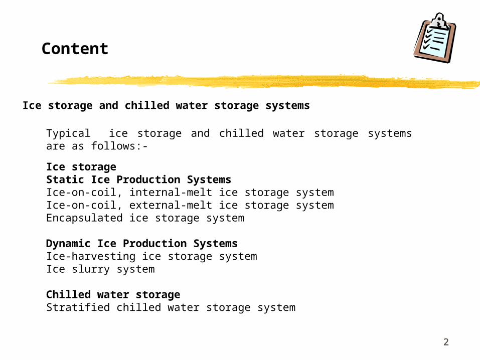
Typical ice storage and chilled water storage systems are as follows:-
Ice storage Static Ice Production SystemsIce-on-coil, internal-melt ice storage system Ice-on-coil, external-melt ice storage systemEncapsulated ice storage system
Dynamic Ice Production SystemsIce-harvesting ice storage systemIce slurry system
Chilled water storageStratified chilled water storage system
Ice storage and chilled water storage systems
Content

3
ICE-ON-COIL, INTERNAL-MELT ICE STORAGE SYSTEM
444
ICE-ON-COIL, INTERNAL-MELT ICE STORAGE SYSTEM
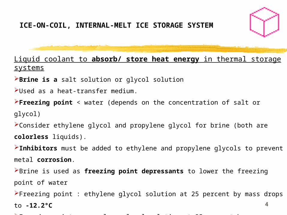
Liquid coolant to absorb/ store heat energy in thermal storage systems
Brine is a salt solution or glycol solution
Used as a heat-transfer medium.
Freezing point < water (depends on the concentration of salt or glycol)
Consider ethylene glycol and propylene glycol for brine (both are colorless
liquids).
Inhibitors must be added to ethylene and propylene glycols to prevent metal
corrosion.
Brine is used as freezing point depressants to lower the freezing point of water
Freezing point : ethylene glycol solution at 25 percent by mass drops to -12.2°C
Freezing point : propylene glycol solution at 25 percent by mass drops to -9.4°C.
Therefore, ethylene glycol solution is preferred.
Ethylene glycol solution with 25-30% ethylene glycol circulates inside tubes at -
4.4°C.
55
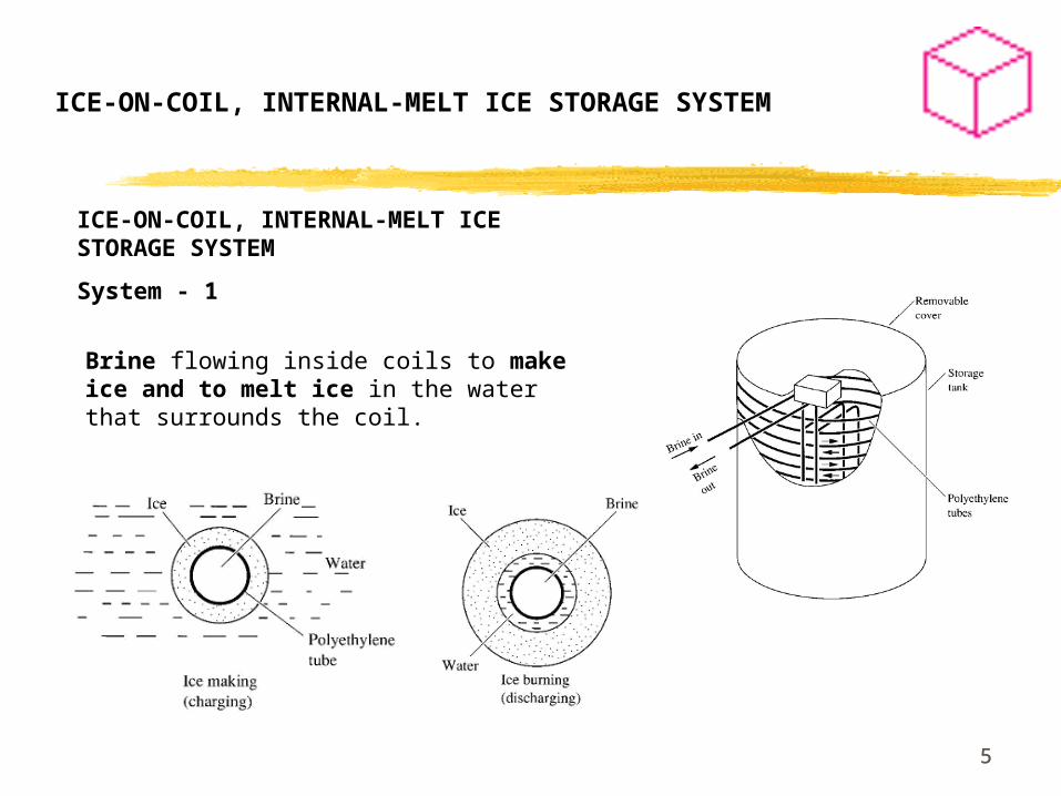
ICE-ON-COIL, INTERNAL-MELT ICE STORAGE SYSTEM
System - 1
Brine flowing inside coils to make ice and to melt ice in the water that surrounds the coil.
ICE-ON-COIL, INTERNAL-MELT ICE STORAGE SYSTEM
66
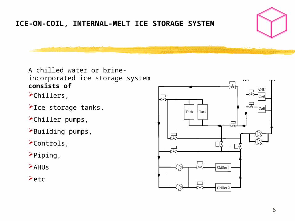
Chillers,
Ice storage tanks,
Chiller pumps,
Building pumps,
Controls,
Piping,
AHUs
etc
A chilled water or brine-incorporated ice storage system consists of
ICE-ON-COIL, INTERNAL-MELT ICE STORAGE SYSTEM
77
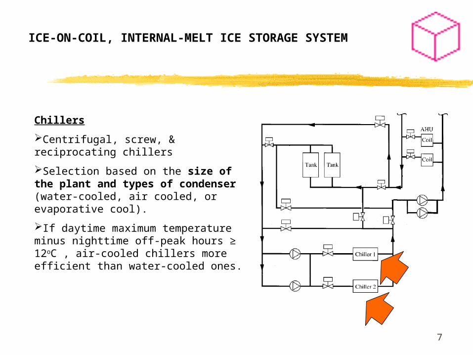
Chillers
Centrifugal, screw, & reciprocating chillers
Selection based on the size of the plant and types of condenser (water-cooled, air cooled, or evaporative cool).
If daytime maximum temperature minus nighttime off-peak hours ≥ 12oC , air-cooled chillers more efficient than water-cooled ones.
ICE-ON-COIL, INTERNAL-MELT ICE STORAGE SYSTEM
88
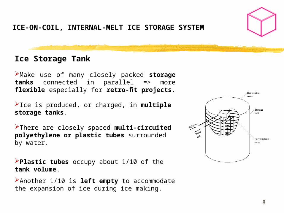
Ice Storage Tank Make use of many closely packed storage tanks connected in parallel => more flexible especially for retro-fit projects.
Ice is produced, or charged, in multiple storage tanks.
There are closely spaced multi-circuited polyethylene or plastic tubes surrounded by water.
Plastic tubes occupy about 1/10 of the tank volume.
Another 1/10 is left empty to accommodate the expansion of ice during ice making.
ICE-ON-COIL, INTERNAL-MELT ICE STORAGE SYSTEM
99
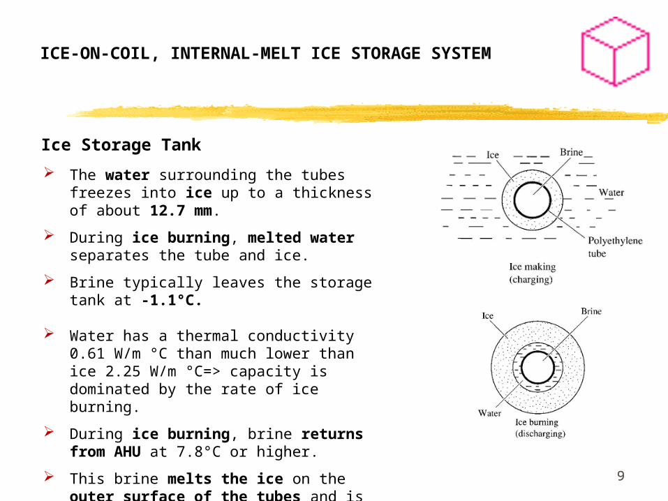
The water surrounding the tubes freezes into ice up to a thickness of about 12.7 mm.
During ice burning, melted water separates the tube and ice.
Brine typically leaves the storage tank at -1.1°C.
Water has a thermal conductivity 0.61 W/m °C than much lower than ice 2.25 W/m °C=> capacity is dominated by the rate of ice burning.
During ice burning, brine returns from AHU at 7.8°C or higher.
This brine melts the ice on the outer surface of the tubes and is thus cooled to 1.1 to 2.2°C.
ICE-ON-COIL, INTERNAL-MELT ICE STORAGE SYSTEM
Ice Storage Tank

1010
Example : Demand-limited partial-storage strategy
For summer cooling, the daily 24-h operating cycle can be divided into three periods: off-peak, direct cooling and on-peak.
Off-peak: Ice is charged to reduce energy costs.
On-peak: Ice is burned to reduce the demand charge. One chiller is operated.
ICE-ON-COIL, INTERNAL-MELT ICE STORAGE SYSTEM

1111
OFF-PEAK1) Ice making :Charge ice tanks2) Direct cooling: Chiller(s) for night
load
ICE-ON-COIL, INTERNAL-MELT ICE STORAGE SYSTEM
-6°C
Both ChillersLoad limit = 100%
1.1°C
Chiller Pump : High speed (ice making)
1)Higher flow rate
2)Pressure drop in evaporator & coils in ice storage tanks.
Tanks sensors :
100 percent charged => terminate ice-making
90 percent ice inventory => ice-making restart
Ethylene glycol solution
1212
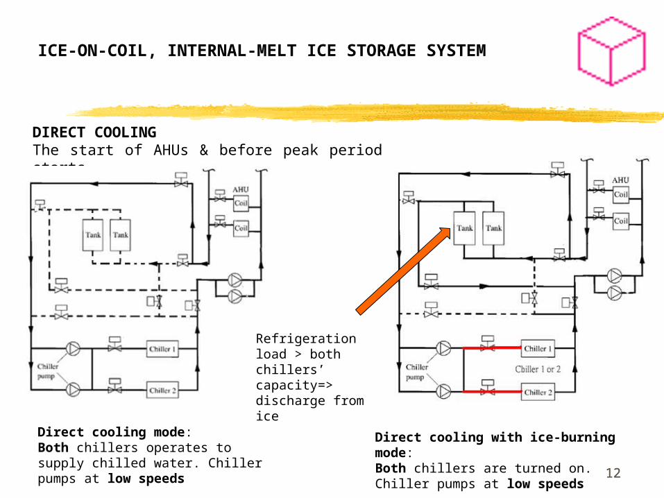
DIRECT COOLINGThe start of AHUs & before peak period starts.
ICE-ON-COIL, INTERNAL-MELT ICE STORAGE SYSTEM
Direct cooling mode: Both chillers operates to supply chilled water. Chiller pumps at low speeds
Direct cooling with ice-burning mode: Both chillers are turned on. Chiller pumps at low speeds
Refrigeration load > both chillers’ capacity=> discharge from ice

1313
ON-PEAK
1) Ice-burning : chiller at demand limit mode
2) Ice-burning without chiller mode
ICE-ON-COIL, INTERNAL-MELT ICE STORAGE SYSTEM
Chiller 1 or 2 lead/lag sequence. Load limit of chiller.
0°C
Both pumps during ice burning at low speed
1.1°C
Greater head : pressure drop of AHU & coil in ice tanks
14
ICE-ON-COIL, EXTERNAL-MELT ICE STORAGE SYSTEMS
1515
ICE-ON-COIL, EXTERNAL-MELT ICE STORAGE SYSTEMS
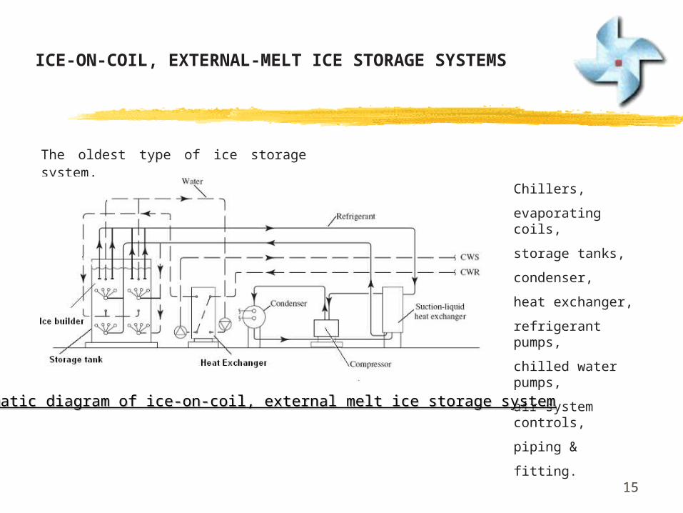
Chillers,
evaporating coils,
storage tanks,
condenser,
heat exchanger,
refrigerant pumps,
chilled water pumps,
air system controls,
piping &
fitting.Schematic diagram of ice-on-coil, external melt ice storage systemSchematic diagram of ice-on-coil, external melt ice storage system
The oldest type of ice storage system.
1616
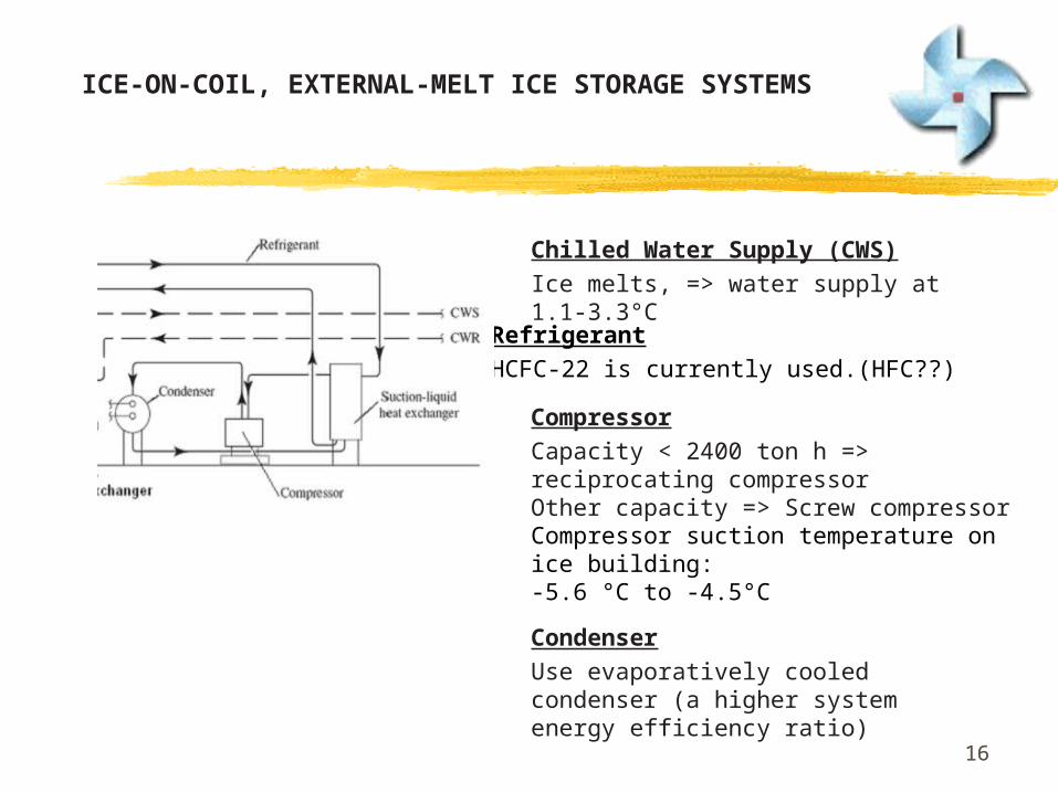
CompressorCapacity < 2400 ton h => reciprocating compressorOther capacity => Screw compressorCompressor suction temperature on ice building: -5.6 °C to -4.5°C
CondenserUse evaporatively cooled condenser (a higher system energy efficiency ratio)
Chilled Water Supply (CWS) Ice melts, => water supply at 1.1-3.3°C
RefrigerantHCFC-22 is currently used.(HFC??)
ICE-ON-COIL, EXTERNAL-MELT ICE STORAGE SYSTEMS
1717
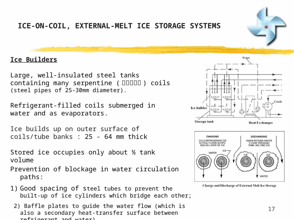
Ice Builders
Large, well-insulated steel tanks containing many serpentine ( 彎彎曲曲的 ) coils (steel pipes of 25-30mm diameter).
Refrigerant-filled coils submerged in water and as evaporators.
Ice builds up on outer surface of coils/tube banks : 25 - 64 mm thick
Stored ice occupies only about ½ tank volume
Prevention of blockage in water circulation paths:
1) Good spacing of steel tubes to prevent the built-up of ice cylinders which bridge each other;
2) Baffle plates to guide the water flow (which is also a secondary heat-transfer surface between refrigerant and water)
ICE-ON-COIL, EXTERNAL-MELT ICE STORAGE SYSTEMS
18
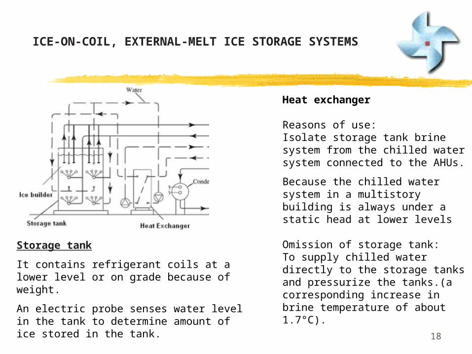
Heat exchanger
Reasons of use: Isolate storage tank brine system from the chilled water system connected to the AHUs.
Because the chilled water system in a multistory building is always under a static head at lower levels
Omission of storage tank:To supply chilled water directly to the storage tanks and pressurize the tanks.(a corresponding increase in brine temperature of about 1.7°C).
Storage tank
It contains refrigerant coils at a lower level or on grade because of weight.
An electric probe senses water level in the tank to determine amount of ice stored in the tank.
ICE-ON-COIL, EXTERNAL-MELT ICE STORAGE SYSTEMS
19
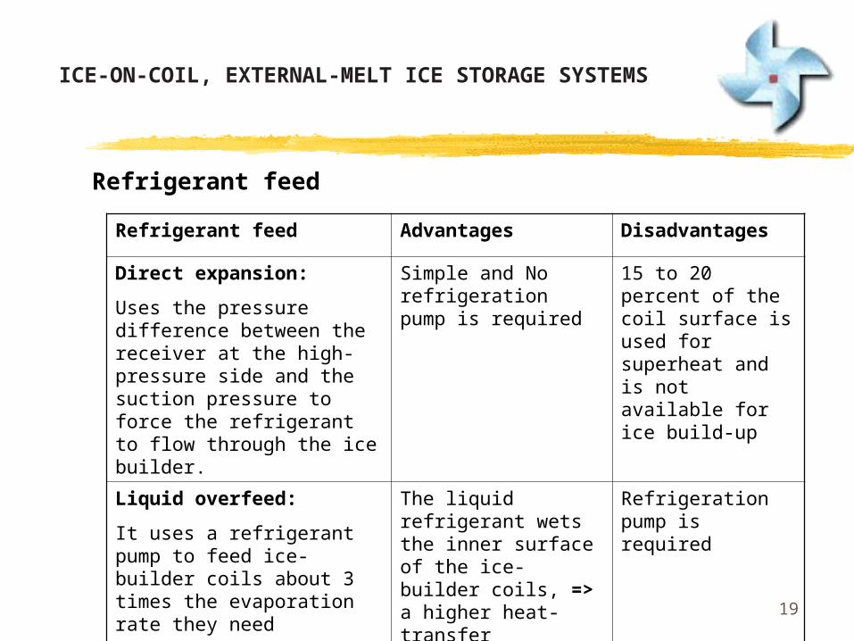
Refrigerant feed Advantages Disadvantages
Direct expansion:
Uses the pressure difference between the receiver at the high-pressure side and the suction pressure to force the refrigerant to flow through the ice builder.
Simple and No refrigeration pump is required
15 to 20 percent of the coil surface is used for superheat and is not available for ice build-up
Liquid overfeed:
It uses a refrigerant pump to feed ice-builder coils about 3 times the evaporation rate they need
The liquid refrigerant wets the inner surface of the ice-builder coils, => a higher heat-transfer coefficient than direct expansion
Refrigeration pump is required
Refrigerant feed
ICE-ON-COIL, EXTERNAL-MELT ICE STORAGE SYSTEMS

20
ENCAPSULATED ICE STORAGE SYSTEMS
2121
ENCAPSULATED ICE STORAGE SYSTEMS
An encapsulated ice storage system consists of:
chillers,
steel tank,
encapsulated containers,
pumps,
air system controls,
piping,
and accessories.
Charging: Secondary coolant is circulated through the tank.
Discharging : Returned warm coolant from AHUs circulated through tank => ice melted.
Direct cooling: Chillers => direct cooling at a coolant temperature from 2 to 6°C.

2222
Chiller upstream Chiller downstream
Chillers and storage tanks are usually connected in series
When partial storage is used, two arrangements are possible:
1) chiller upstream or 1) chiller downstream
ENCAPSULATED ICE STORAGE SYSTEMS

2323
Chiller upstream
Chilled water returned from AHUs at 8°C is first cooled in the chiller to 4°C, and then it enters the storage tank and is cooled down to 1°C.
Advantage:Chilled water cooled at the chiller is at a higher temperature => a higher COP at the chiller.
Disadvantage:Usable portion of the total storage capacity is reduced because of the lower storage tank discharge temperature
8°C
4°C
1°C
ENCAPSULATED ICE STORAGE SYSTEMS

2424
Chiller downstream
Chilled water returned from AHU at 8°C is often first cooled in the storage tank to 4°C, and then it enters the chiller and is cooled down to 1°C.
Disadvantage:COP of the chiller is lower,
Advantage:The usable portion of the total storage capacity of the ice storage tanks is increased.
8°C
4°C1°C
ENCAPSULATED ICE STORAGE SYSTEMS
2525
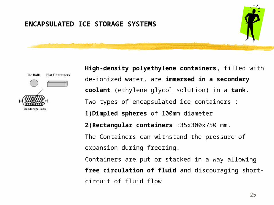
High-density polyethylene containers, filled with de-
ionized water, are immersed in a secondary coolant
(ethylene glycol solution) in a tank.
Two types of encapsulated ice containers :
1)Dimpled spheres of 100mm diameter
2)Rectangular containers :35x300x750 mm.
The Containers can withstand the pressure of expansion
during freezing.
Containers are put or stacked in a way allowing free
circulation of fluid and discouraging short-circuit of fluid
flow
ENCAPSULATED ICE STORAGE SYSTEMS

2626
Storage Tank - Open, non-pressurized type
It needs a barrier to keep the frozen containers submerged into the coolant.
Ice-charging inventory in the storage tank is measured based on the displacement of water in the tank when the ice is formed inside the encapsulated containers.
A static pressure transducer is often used to detect the water level in the storage tank.
Storage Tank- Pressurized type
Expansion of the frozen containers forces the secondary coolant overflowing into a separate inventory tank, and its water level is measured.
ENCAPSULATED ICE STORAGE SYSTEMS
2727
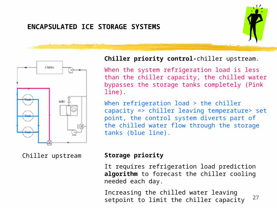
Chiller priority control-chiller upstream.
When the system refrigeration load is less than the chiller capacity, the chilled water bypasses the storage tanks completely (Pink line).
When refrigeration load > the chiller capacity => chiller leaving temperature> set point, the control system diverts part of the chilled water flow through the storage tanks (blue line).
Storage priority
It requires refrigeration load prediction algorithm to forecast the chiller cooling needed each day.
Increasing the chilled water leaving setpoint to limit the chiller capacity
Most of or all the refrigeration load is by ice storage.
Chiller upstream
ENCAPSULATED ICE STORAGE SYSTEMS

28
ICE-HARVESTING ICE STORAGE SYSTEMS
2929
ICE-HARVESTING ICE STORAGE SYSTEMS
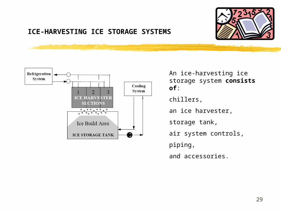
An ice-harvesting ice storage system consists of:
chillers,
an ice harvester,
storage tank,
air system controls,
piping,
and accessories.
3030
ICE-HARVESTING ICE STORAGE SYSTEMS
Equipment
Ice is produced in a harvester, which is
separate from the storage tank where ice
is stored.
The evaporator of the chiller is a vertical
plate heat exchanger mounted above a
water / ice storage tank.
Low-pressure liquid refrigerant is forced
through the inner part of the plate heat
exchanger is vaporized =>
refrigeration effect.
3131
ICE-HARVESTING ICE STORAGE SYSTEMS
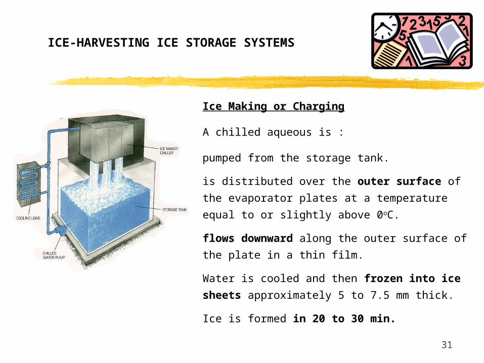
Ice Making or Charging
A chilled aqueous is :
pumped from the storage tank.
is distributed over the outer surface of the
evaporator plates at a temperature equal to or
slightly above 0oC.
flows downward along the outer surface of the
plate in a thin film.
Water is cooled and then frozen into ice
sheets approximately 5 to 7.5 mm thick.
Ice is formed in 20 to 30 min.

3232
Ice harvesting
Ice is harvested,in the form of flakes or chunks and
falls into the storage tank below.
Periodically, hot gas is introduced into 1/4
evaporator plates by reversing the refrigerant flow.
Ice is harvested within 20 to 40s (plate evaporator
acts as condenser).
Ice accumulates about 60 percent of storage tank
volume.
The ice flakes are around 150 mm by 150 mm by 6
mm
But melting of the ice during the harvesting
process decreases the amount of ice harvested and
adds an incremental refrigeration load to the system.
ICE-HARVESTING ICE STORAGE SYSTEMS

3333
Other considerations
Successfully used in load shifting and
load leveling to reduce electric demand
and energy cost.
It is an open system. More water
treatment is required than in an ice-on-
coil, internal-melt ice storage system
Evaporator plates must be located above
the storage tank, ice-harvesting systems
need more headroom
ICE-HARVESTING ICE STORAGE SYSTEMS
34
SLURRY ICE SYSTEM
35
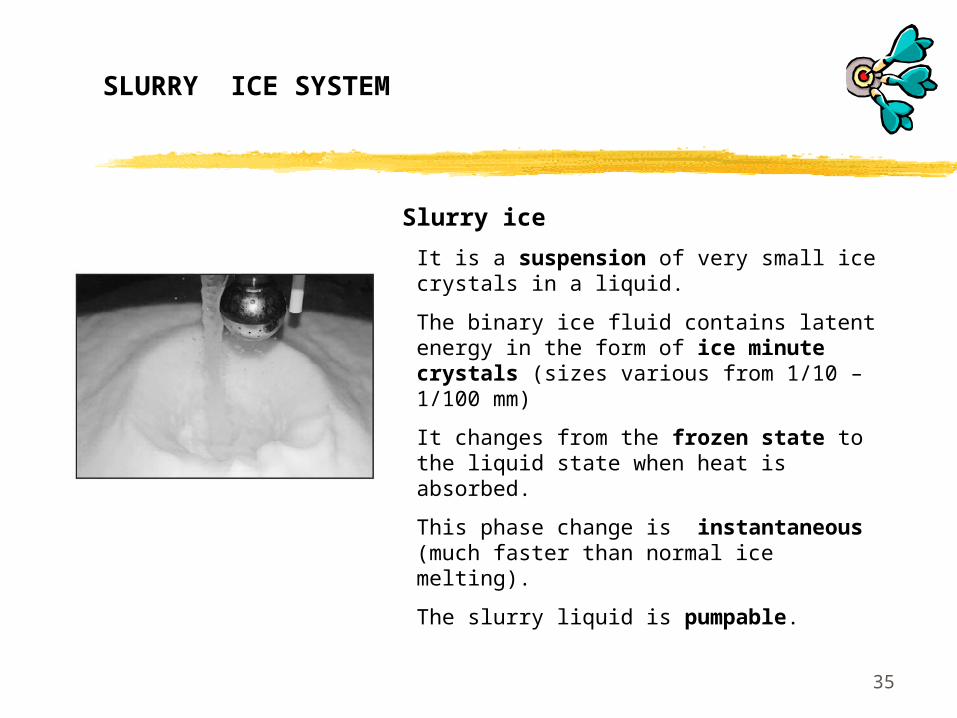
It is a suspension of very small ice crystals in a liquid.
The binary ice fluid contains latent energy in the form of ice minute crystals (sizes various from 1/10 – 1/100 mm)
It changes from the frozen state to the liquid state when heat is absorbed.
This phase change is instantaneous (much faster than normal ice melting).
The slurry liquid is pumpable.
Slurry ice
SLURRY ICE SYSTEM
36
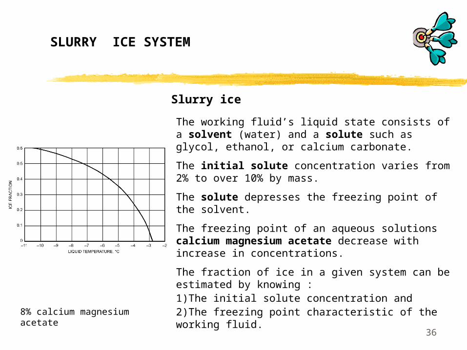
The working fluid’s liquid state consists of a solvent (water) and a solute such as glycol, ethanol, or calcium carbonate.
The initial solute concentration varies from 2% to over 10% by mass.
The solute depresses the freezing point of the solvent.
The freezing point of an aqueous solutions calcium magnesium acetate decrease with increase in concentrations.
The fraction of ice in a given system can be estimated by knowing :1)The initial solute concentration and 2)The freezing point characteristic of the working fluid.
Slurry ice
8% calcium magnesium acetate
SLURRY ICE SYSTEM
3737
Advantages of Slurry ice storage system
The Slurry-Ice system is a dynamic type ice storage system which offers the pumpable characteristic advantage over any other type of dynamic systems. and the icy slurry can be pumped
Slurry-Ice is a very versatile cooling medium: The handling characteristics, and cooling capacities can match any application by adjusting the percentage of ice concentration.
Slurry-Ice does not suffer from the static type disadvantages of ice bridging and ice insulation effects.
Slurry-Ice instantly melts to meet varying cooling load. Hence, ensuring steady and accurate system leaving temperature control.
SLURRY ICE SYSTEM

38
Conventional chilled water systems
The enthalphy difference of water between 6 and 12oC => a cooling capacity of 30 kJ/kg.
Slurry ice Cooling System
The latent heat carried by ice particles in the water adds great cooling capacity to the flow.
The cooling capacity of slurry ice operation at 0/13 oC with ice fraction of 20% equals to 144 kJ/kg.
The use of slurry ice significantly decreases the volumetric flow requirements.
Comparison on cooling capacity
SLURRY ICE SYSTEM
39
SLURRY ICE SYSTEM

40
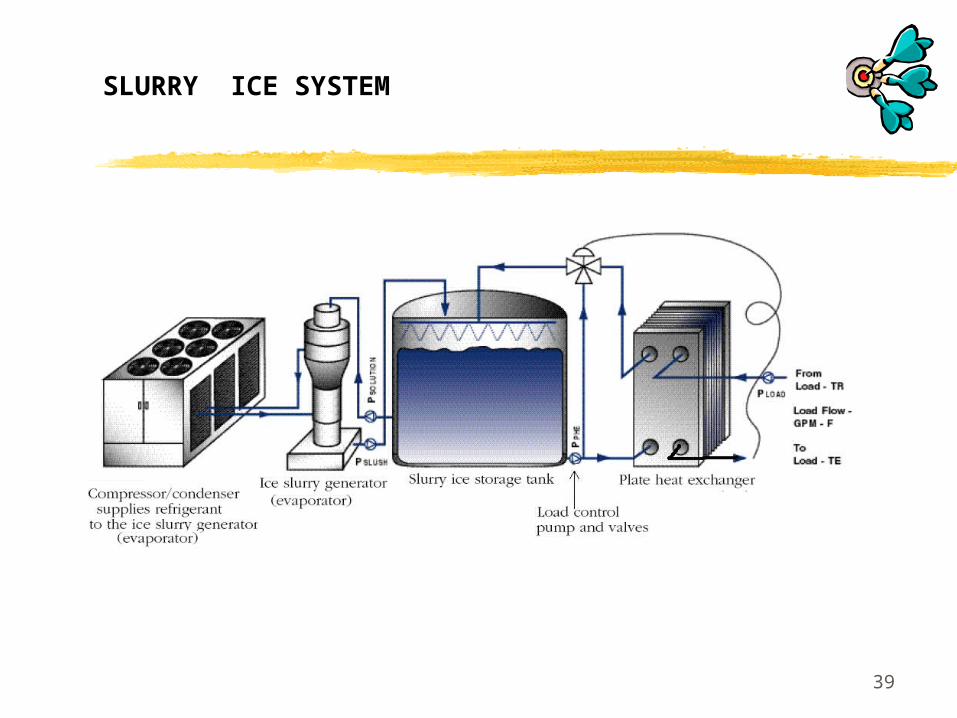
Compressor/Condenser
It supplies refrigerant to the evaporator.
Ice Slurry Generator (evaporator)
Water & freeze depressant mixture to produce a pumpable ice slurry.
Options of Generators are as follows: -
Supercooled Slurry Ice Generator
Scraper Type Slurry Generator
Ejector System
Vacuum Type Slurry Ice Generator
Falling Film Type Slurry Ice Machine
SLURRY ICE SYSTEM

41
Falling Film Type Slurry Ice Machine
The internal falling film process is based on supercooling the solution which is disturbed by a spinning rod in order to overcome the formation of solid ice and prevent it sticking to the inner surface of the pipe.
Once the solution is supercooled and disturbed, it forms microscopic fine binary ice crystals which are collected at the bottom of the vessel.
The ice concentration and capacity control can be adjusted by either controlling suction pressure, solution flow rates or both.
Low friction between the rod and the tube wall and the slurry ice solution acts like a lubricant.
SLURRY ICE SYSTEM

42
It separates ice manufacturing from ice usage.
The tank contains a glycol/water solution which
is converted to an ice slurry in the ice slurry
generator.
The slurry melts as the stored ice absorbs the
heat of the cooling load.
Insulated Ice Storage Tank
SLURRY ICE SYSTEM
43
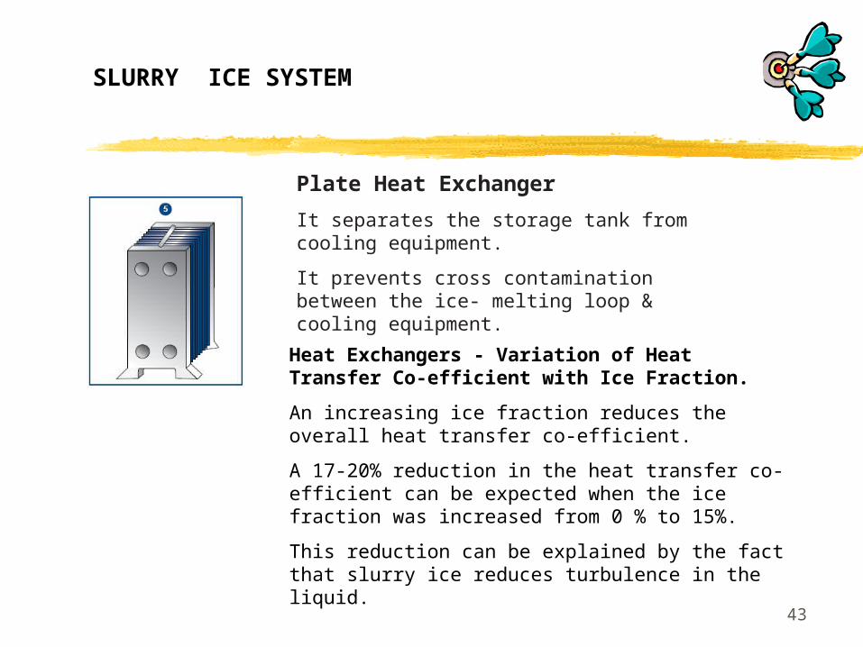
Heat Exchangers - Variation of Heat Transfer Co-efficient with Ice Fraction.
An increasing ice fraction reduces the overall heat transfer co-efficient.
A 17-20% reduction in the heat transfer co-efficient can be expected when the ice fraction was increased from 0 % to 15%.
This reduction can be explained by the fact that slurry ice reduces turbulence in the liquid.
Plate Heat Exchanger
It separates the storage tank from cooling equipment.
It prevents cross contamination between the ice- melting loop & cooling equipment.
SLURRY ICE SYSTEM

44
Load Control Pump and Valve
For provide the flow and control the supply temperature to the load.
A minimum velocity must be maintained for ice fractions between 0.1 and 0.25.
Below this velocity=> the pressure gradient increases when the velocity is decreased=> Phase separation, with ice floating to the top of the pipe, causes the effective liquid flow cross-section to decrease.
A number of pressure drop experiments conducted at slurry ice velocities over 3m/s and ice fractions in excess of 20% in straight tubes with internal diameters of 25, 51 and 76 mm indicate no difference in pressure gradient between water and slurry ice.
At at slurry ice velocities < 1 m/s, the loop pressure drop was slightly above the pressure drop of the water.
SLURRY ICE SYSTEM

45
STRATIFIED CHILLED WATER STORAGE SYSTEMS

46
A large storage tank to store chilled water (4-7oC).
To shift the load to the off-peak hours and reduces the energy cost.
The chilled water incorporated storage system consist of
Chillers,
A cylindrical storage tank,
Pumps,
Piping,
Accessories
etc Chilled Water Storage System
STRATIFIED CHILLED WATER STORAGE SYSTEMS
4747
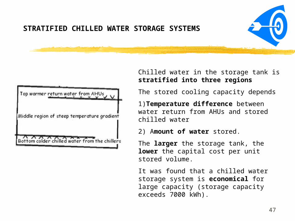
Chilled water in the storage tank is stratified into three regions
The stored cooling capacity depends
1)Temperature difference between water return from AHUs and stored chilled water
2) Amount of water stored.
The larger the storage tank, the lower the capital cost per unit stored volume.
It was found that a chilled water storage system is economical for large capacity (storage capacity exceeds 7000 kWh).
STRATIFIED CHILLED WATER STORAGE SYSTEMS
4848
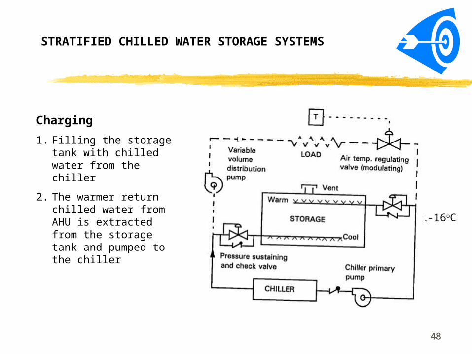
Charging
1. Filling the storage tank with chilled water from the chiller
2. The warmer return chilled water from AHU is extracted from the storage tank and pumped to the chiller
4-7oC
11-16oC
STRATIFIED CHILLED WATER STORAGE SYSTEMS
49
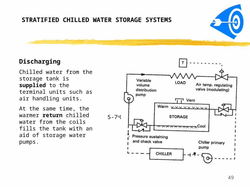
Discharging
Chilled water from the storage tank is supplied to the terminal units such as air handling units.
At the same time, the warmer return chilled water from the coils fills the tank with an aid of storage water pumps.
5-7oC,
STRATIFIED CHILLED WATER STORAGE SYSTEMS

5050
Figure of merit (FOM)
It is used to indicate the loss of cooling capacity of the stored chilled water during the charging and discharging processes.
STRATIFIED CHILLED WATER STORAGE SYSTEMS

5151
The smaller the difference between outlet temperature of stored chilled water during discharging and the inlet temperature of stored chilled water during charging, the higher the FOM.
The smaller the losses of cooling capacity during chilled water storage, the greater the value of FOM.
Well-designed storage tanks have
FOM = or > 90% for daily complete charge/discharge cycles
FOM : 80 % and 90% for partial charge/discharge cycles.
Figure of merit (FOM)
STRATIFIED CHILLED WATER STORAGE SYSTEMS

52
Stratified tank, Membrane tank and Empty tank
The stratified tank is the simplest and most efficient method.
Stratified tanks are widely used in chilled water storage installations.
A membrane tank is a storage tank in which a membrane separates the colder stored chilled water and warmer return water.
An empty tank is a storage tank in which walls are used to separate the colder and warmer chilled water.
Compared with membrane tanks and empty tanks, stratified tanks have the advantages of simpler construction and control, greater storage capacity, and lower cost.
It was found that there is no significant difference in FOM between stratified tanks and membrane tanks or empty tanks.
Storage Tanks
STRATIFIED CHILLED WATER STORAGE SYSTEMS
5353
Chilled water storage tanks are usually flat-bottomed vertical cylinders.
A cylindrical tank has a lower surface-to-volume ratio than a rectangular tank.
Large cylindrical tanks typically have a height-to-diameter ratio of 0.25 to 0.35.
Steel is the commonly used material for above-grade tanks, and concrete is widely used for underground tanks.
All outdoor above-grade structures should have a minimum of 50mm thick external insulation layer spray-on polyurethane foam, a vapor barrier, and a highly reflective top coating.
STRATIFIED CHILLED WATER STORAGE SYSTEMS
Storage Tanks

5454
Stratified tanks rely on the buoyancy of warmer return chilled water, which is lighter than colder chilled water, to separate these two chilled waters during charging and discharging.
Diffusers are used to lower entering and leaving water velocity to prevent mixing (<0.3 m/s).
Colder stored chilled water is always charged from the bottom diffusers which is also for discharge.
The warmer return chilled water is introduced to and withdrawn from the tank through the top lateral diffusers.
Field measurements shows that stratified tanks have a figure of merit between 0.85 and 0.92.
STRATIFIED CHILLED WATER STORAGE SYSTEMS
Storage Tanks

5555
Vertical temperature profiles
Formed during charging or discharging in stratified tanks at various time intervals.
Illustrated on a height-temperature diagram at the beginning, the middle, and near the end of the charging process.
In the middle of the charging process along the vertical height of storage tank, chilled water is divided into three regions:
1. Bottom colder-and-heavier stored chilled water
2. Thermocline
3. Top warmer-and lighter return chilled water.
STRATIFIED CHILLED WATER STORAGE SYSTEMS
5656
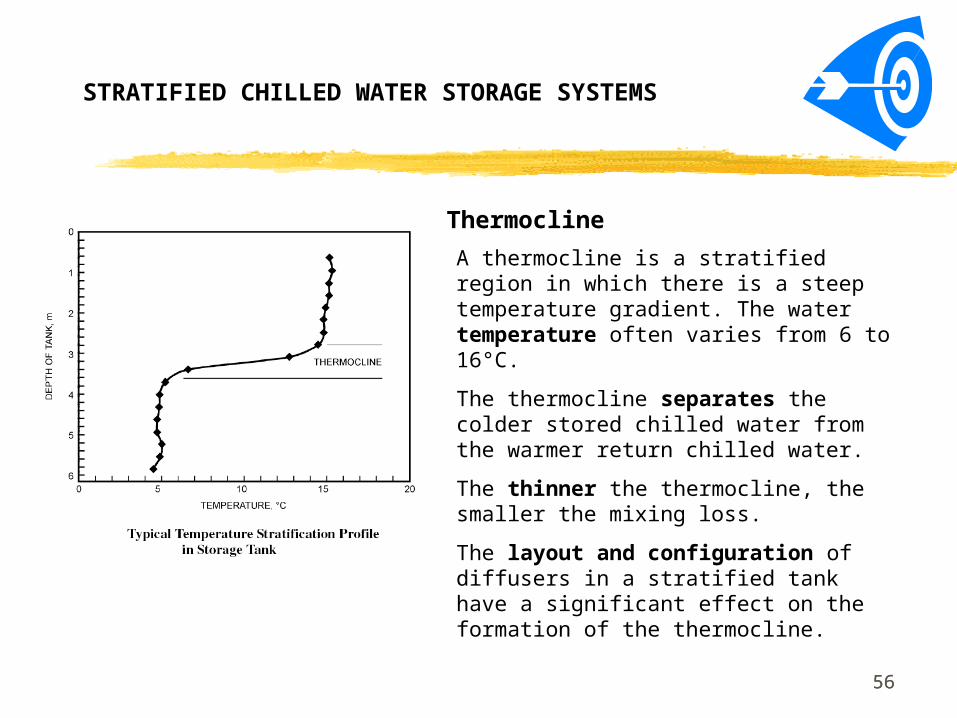
A thermocline is a stratified region in which there is a steep temperature gradient. The water temperature often varies from 6 to 16°C.
The thermocline separates the colder stored chilled water from the warmer return chilled water.
The thinner the thermocline, the smaller the mixing loss.
The layout and configuration of diffusers in a stratified tank have a significant effect on the formation of the thermocline.
Thermocline
STRATIFIED CHILLED WATER STORAGE SYSTEMS
5757
The inlet temperature of chilled water should be controlled within a narrow band (say + or - 1°C) during charging to avoid additional mixing.
Mixing at at the start of the charging and discharging processes.
Mixing at formation of the thermocline, and at the inlet side of the thermocline after the thermocline has been formed.
Mixing near the inlet diffuser (Incoming chilled water initially forms a thin layer of gravity current that slowly pushes the chilled water originally in the tank out of the way so that mixing only occurs at the front of the gravity current).
Mixing
STRATIFIED CHILLED WATER STORAGE SYSTEMS
5858
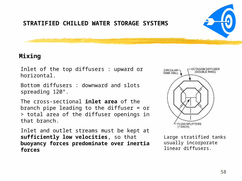
Inlet of the top diffusers : upward or horizontal.
Bottom diffusers : downward and slots spreading 120°.
The cross-sectional inlet area of the branch pipe leading to the diffuser = or > total area of the diffuser openings in that branch.
Inlet and outlet streams must be kept at sufficiently low velocities, so that buoyancy forces predominate over inertia forces
Large stratified tanks usually incorporate linear diffusers.
Mixing
STRATIFIED CHILLED WATER STORAGE SYSTEMS

5959
The inlet Reynolds number is closely related to the inlet velocity and is defined as
wv
qRe i
Where
q = Volume flow rate per unit diff user length (m3/ s.m)
vw = Kinematic viscosity of water (m2/ s)
When Rei < 850, loss due to mixing and loss of cooling capacity during discharge can be significantly reduced.
Mixing on the inlet side of thermocline depends on the inlet Reynolds number Rei and Froude number Fri.
STRATIFIED CHILLED WATER STORAGE SYSTEMS

6060
5.0
3 )(
i
aii
i
gh
qFr
The inlet Froude number Fri is defined as
Where
q = Volume flow rate per unit diff user length (m3/ s.m)
g = Acceleration of gravity (m/ s2)
hi = I nlet opening height (m)
ρ i = Density of inlet water (kg/ m3)
ρ a = Density of ambient water (kg/ m3)
STRATIFIED CHILLED WATER STORAGE SYSTEMS
6161
Inlet opening height
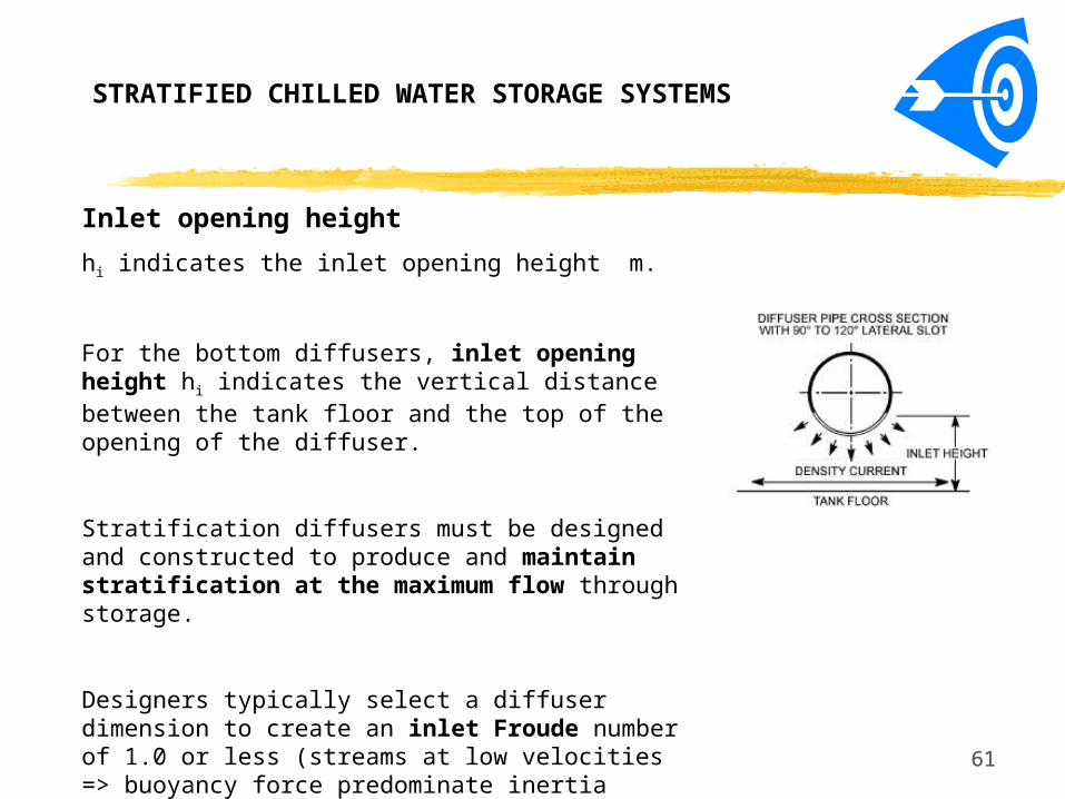
hi indicates the inlet opening height m.
For the bottom diffusers, inlet opening height hi indicates the vertical distance between the tank floor and the top of the opening of the diffuser.
Stratification diffusers must be designed and constructed to produce and maintain stratification at the maximum flow through storage.
Designers typically select a diffuser dimension to create an inlet Froude number of 1.0 or less (streams at low velocities => buoyancy force predominate inertia force).
STRATIFIED CHILLED WATER STORAGE SYSTEMS

6262
The piping design should be symmetric.
1. Branch pipes should be equal in length.
2. Flow splitters should be added at the appropriate points.
3. Pipe diameter reduction should be combined with the flow splitter.
4. Long-radius elbows should be used.
Self-balancing
It should be achieved on evenly distribution of the flow by:
STRATIFIED CHILLED WATER STORAGE SYSTEMS

6363
Exposed tank surfaces should be insulated to maintain the temperature differential in the tank.
Insulation is especially important for smaller storage tanks (high surface area to stored volume ratio).
Heat transfer between the stored water and the tank contact surfaces (including divider walls) is a primary source of capacity loss.
Storage Tank Insulation
STRATIFIED CHILLED WATER STORAGE SYSTEMS
64
1. Internal melt ice-on-coil systems are the most commonly used type of ice storage technology in commercial applications.
2. External melt and ice harvesting systems are more common in industrial applications, although they can also be applied in commercial buildings and district cooling systems.
3. Encapsulated ice systems are also suitable for many commercial applications.
4. Ice slurry systems have not been widely used in commercial applications.
See also the attached table.
A Comparison – From Some Papers


Question and AnswerQuestion and Answer