Measurements of gun tube motion and muzzle pointing...
11
157 Measurements of gun tube motion and muzzle pointing error of main battle tanks Peter L. McCall US Army Aberdeen Test Center, Aberdeen Proving Ground, MD 21005-5059, USA Beginning in 1990, the US Army Aberdeen Test Center (ATC) began testing a prototype cannon mounted in a non-armored turret fitted to an M1A1 Abrams tank chassis. The cannon design incorporated a longer gun tube as a means to increase projectile velocity. A significant increase in projectile impact dispersion was measured early in the test program. Through investigative efforts, the cause of the error was linked to the increased dynamic bending or flexure of the longer tube ob- served while the vehicle was moving. Research and inves- tigative work was conducted through a collaborative effort with the US Army Research Laboratory, Benet Laboratory, Project Manager – Tank Main Armament Systems, US Army Research and Engineering Center, and Cadillac Gage Textron Inc. New test methods, instrumentation, data analysis proce- dures, and stabilization control design resulted through this series of investigations into the dynamic tube flexure error source. Through this joint research, improvements in tank fire control design have been developed to improve delivery accuracy. This paper discusses the instrumentation imple- mented, methods applied, and analysis procedures used to characterize the tube flexure during dynamic tests of a main battle tank and the relationship between gun pointing error and muzzle pointing error. 1. Introduction Consider for the moment that you are on a test range firing the main gun from a prototype main battle tank moving over rough terrain. You just missed the target. Why? There are many factors that govern the prob- ability of a projectile hitting an intended target. The projectile’s trajectory, prevailing winds, aiming error, target motion, the motion of the firing platform, and propellant temperature are just some of the many vari- ables which influence where the projectile will impact. The flight of the projectile after it leaves the muzzle and how the environment interacts with its trajectory has been the subject of extensive research. Today, if we were to launch a projectile from point ‘A’, wish it to impact point ‘B’, and know what the environment is between points ‘A’ and ‘B’, we can predict with a high degree of accuracy where we need to point the gun. Re- ferring back to our original question and knowing that the projectile is flying as it should, we make the obvious conclusion that the gun is not pointed correctly. Yet the tank system outputs and on-board instrumentation are telling us that the gun is indeed pointed where it should be. Why did the projectile miss? This is where the story begins ... 2. History of fire control design and test methods The fire control systems on the M60 and M1 series tanks have, for all intents and purposes, treated the gun tube as a rigid beam. The centerline of the tube bore is aligned with the gunner’s sight. This boresight alignment is then periodically realigned using a Muz- zle Reference System (MRS) to compensate for static deflections caused by uneven cooling or heating of the tube. The gun is offset relative to the line-of-sight so that the projectile will impact the target at some given range. This gun pointing direction consists of an offset to account for the ballistics involved to hit the target (called ballistic offset), a correction for parallax be- tween sight and gun, and an additional offset for ballis- tic jump (called ‘zero correction’). The ballistic offset includes such things as the trajectory of the projectile, wind influence, induced lead if the target or vehicle are moving, ammunition temperature, air temperature, etc. Parallax error is a geometric error due to the location of the sight relative to the centerline of the gun. The bal- listic jump is corrections from the boresight alignment to compensate for launch characteristics of a projectile type. Historically, the error or deviation from the cal- culated total gun pointing direction relative to the line- of-sight is measured with respect to the trunnion for the elevation axis and to the turret structure for the azimuth axis. The gun control system attempts to drive these two errors, azimuth and elevation, to zero. The stabi- Shock and Vibration 8 (2001) 157–166 ISSN 1070-9622 / $8.00 2001, IOS Press. All rights reserved
Transcript of Measurements of gun tube motion and muzzle pointing...

157
Measurements of gun tube motion andmuzzle pointing error of main battle tanks
Peter L. McCallUS Army Aberdeen Test Center, Aberdeen ProvingGround, MD 21005-5059, USA
Beginning in 1990, the US Army Aberdeen Test Center (ATC)began testing a prototype cannon mounted in a non-armoredturret fitted to an M1A1 Abrams tank chassis. The cannondesign incorporated a longer gun tube as a means to increaseprojectile velocity. A significant increase in projectile impactdispersion was measured early in the test program. Throughinvestigative efforts, the cause of the error was linked to theincreased dynamic bending or flexure of the longer tube ob-served while the vehicle was moving. Research and inves-tigative work was conducted through a collaborative effortwith the US Army Research Laboratory, Benet Laboratory,Project Manager – Tank Main Armament Systems, US ArmyResearch and Engineering Center, and Cadillac Gage TextronInc. New test methods, instrumentation, data analysis proce-dures, and stabilization control design resulted through thisseries of investigations into the dynamic tube flexure errorsource. Through this joint research, improvements in tankfire control design have been developed to improve deliveryaccuracy. This paper discusses the instrumentation imple-mented, methods applied, and analysis procedures used tocharacterize the tube flexure during dynamic tests of a mainbattle tank and the relationship between gun pointing errorand muzzle pointing error.
1. Introduction
Consider for the moment that you are on a test rangefiring the main gun from a prototype main battle tankmoving over rough terrain. You just missed the target.Why? There are many factors that govern the prob-ability of a projectile hitting an intended target. Theprojectile’s trajectory, prevailing winds, aiming error,target motion, the motion of the firing platform, andpropellant temperature are just some of the many vari-ables which influence where the projectile will impact.The flight of the projectile after it leaves the muzzleand how the environment interacts with its trajectoryhas been the subject of extensive research. Today, if
we were to launch a projectile from point ‘A’, wish itto impact point ‘B’, and know what the environment isbetween points ‘A’ and ‘B’, we can predict with a highdegree of accuracy where we need to point the gun. Re-ferring back to our original question and knowing thatthe projectile is flying as it should, we make the obviousconclusion that the gun is not pointed correctly. Yetthe tank system outputs and on-board instrumentationare telling us that the gun is indeed pointed where itshould be. Why did the projectile miss? This is wherethe story begins . . .
2. History of fire control design and test methods
The fire control systems on the M60 and M1 seriestanks have, for all intents and purposes, treated thegun tube as a rigid beam. The centerline of the tubebore is aligned with the gunner’s sight. This boresightalignment is then periodically realigned using a Muz-zle Reference System (MRS) to compensate for staticdeflections caused by uneven cooling or heating of thetube. The gun is offset relative to the line-of-sight sothat the projectile will impact the target at some givenrange. This gun pointing direction consists of an offsetto account for the ballistics involved to hit the target(called ballistic offset), a correction for parallax be-tween sight and gun, and an additional offset for ballis-tic jump (called ‘zero correction’). The ballistic offsetincludes such things as the trajectory of the projectile,wind influence, induced lead if the target or vehicle aremoving, ammunition temperature, air temperature, etc.Parallax error is a geometric error due to the location ofthe sight relative to the centerline of the gun. The bal-listic jump is corrections from the boresight alignmentto compensate for launch characteristics of a projectiletype. Historically, the error or deviation from the cal-culated total gun pointing direction relative to the line-of-sight is measured with respect to the trunnion for theelevation axis and to the turret structure for the azimuthaxis. The gun control system attempts to drive thesetwo errors, azimuth and elevation, to zero. The stabi-
Shock and Vibration 8 (2001) 157–166ISSN 1070-9622 / $8.00 2001, IOS Press. All rights reserved

158 P.L. McCall / Measurements of gun tube motion and muzzle pointing error of main battle tanks
Fig. 1. Schematic diagram of CMRS optics assembly.
Fig. 2. Transfer function ‘Y’ scan.
lization system does an efficient job of correcting forthe pitch and yaw of the tank as it negotiates the terrain.The gunner corrects translation of the vehicle in the ver-tical and horizontal axis, referred to as heave and slip
respectively, by his re-laying of the reticle (crosshairs)on the target. The disturbance imparted to the tube bythe motion of the vehicle chassis and the gun drivesas it moves over the ground causes flexing in the tube.

P.L. McCall / Measurements of gun tube motion and muzzle pointing error of main battle tanks 159
Fig. 3. Transfer function ‘X’ scan.
Zero-Reference point (sight)ReticleTarget
LE RT
TS
With this control design, the flexing of the tube is notpart of the feedback to the fire control system, which inessence, is pointing the muzzle of the gun in a differentdirection then what the control system believes to becorrect.
The delivery accuracy of these systems is measuredby the use of video cameras. One camera is used tocapture the image the gunner sees in his primary sight,called the ‘through-sight image’. This is done by theuse of a beam splitter in the optical chain. For the M1series tank, the commander’s extension, which alreadyincorporates a beam splitter, is replaced with a camera.A second camera is mounted on the gun mantlet abovethe trunnion and aligned parallel to the bore centerline.This second video signal is called the ‘gun tube image’.A contrasting light source is placed at the target as pointreference. The video signals are processed throughimage contrast trackers to provide three digitized out-puts: Gun Tube (GT), which is the gun pointing di-rection from the initial boresight alignment; Through-
Sight (TS), which is the position of the aimpoint withinthe field-of-view relative to the initial boresight posi-tion; and Reticle (RT), which is the reticle position inthe field-of-view of the through-sight video relative tothe boresight position (applicable to agile reticles). Azero-reference is obtained by locating the reticle on thecenter of the target with the proper ballistic offset ina static condition prior to the data collection of a testrun. The gunner’s Lay Error (LE) or aim error can bedetermined from Eq. (1). Diagrams are provided tohelp with understanding, however, please keep in mindthat these formulas are in two dimensions (azimuth andelevation) and are in this form for easier presentation.These equations apply for a relative constant velocitytarget with respect to the vehicle.
LE = TS − RT (1)
The Absolute Required Lead (ARL) for a moving tar-get or vehicle, is determined by measuring the changein position of the target relative to the tank from time

160 P.L. McCall / Measurements of gun tube motion and muzzle pointing error of main battle tanks
Fig. 4. CMRS azimuth and elevation time history over RRC-9 bump course at 15 mph.
Zero-Reference point (gun)Target @ t Target @ t+tof
ARL-BO-Z TGPE
GT
= t to time = t+ time of flight (tof) of the projectilein the future. The Total Gun Pointing Error (TGPE) ortheoretical miss distance is computed using Eq. (2).
TGPE = GT − ARL − BO − Z (2)
Where ‘BO’ is the required Ballistic Offset, whichincludes the superelevation for the trajectory of theprojectile and corrections for the environment (wind,barometric pressure, air temperature, and propellanttemperature) and ‘Z’ are the zero correction factors.
Target Induced Error (TIE) is that portion of theTGPE resulting from relative target motion between
time = t and time = t + tof that cannot be accountedfor by the system, Eq. (3).
TIE = ARL − dX(t)/dt ∗ tof (3)
Tracking Rate Error (TRE) is the difference betweenthe actual target rate and the gunner’s tracking rate attime = t (see Eq. (4)). This is a function of the gunner’slay error over time.
TRE = dLE(t)/dt (4)
The System Required Lead (SRL) is the amount oflead that should be computed by the system. This is
P.L. McCall / Measurements of gun tube motion and muzzle pointing error of main battle tanks 161
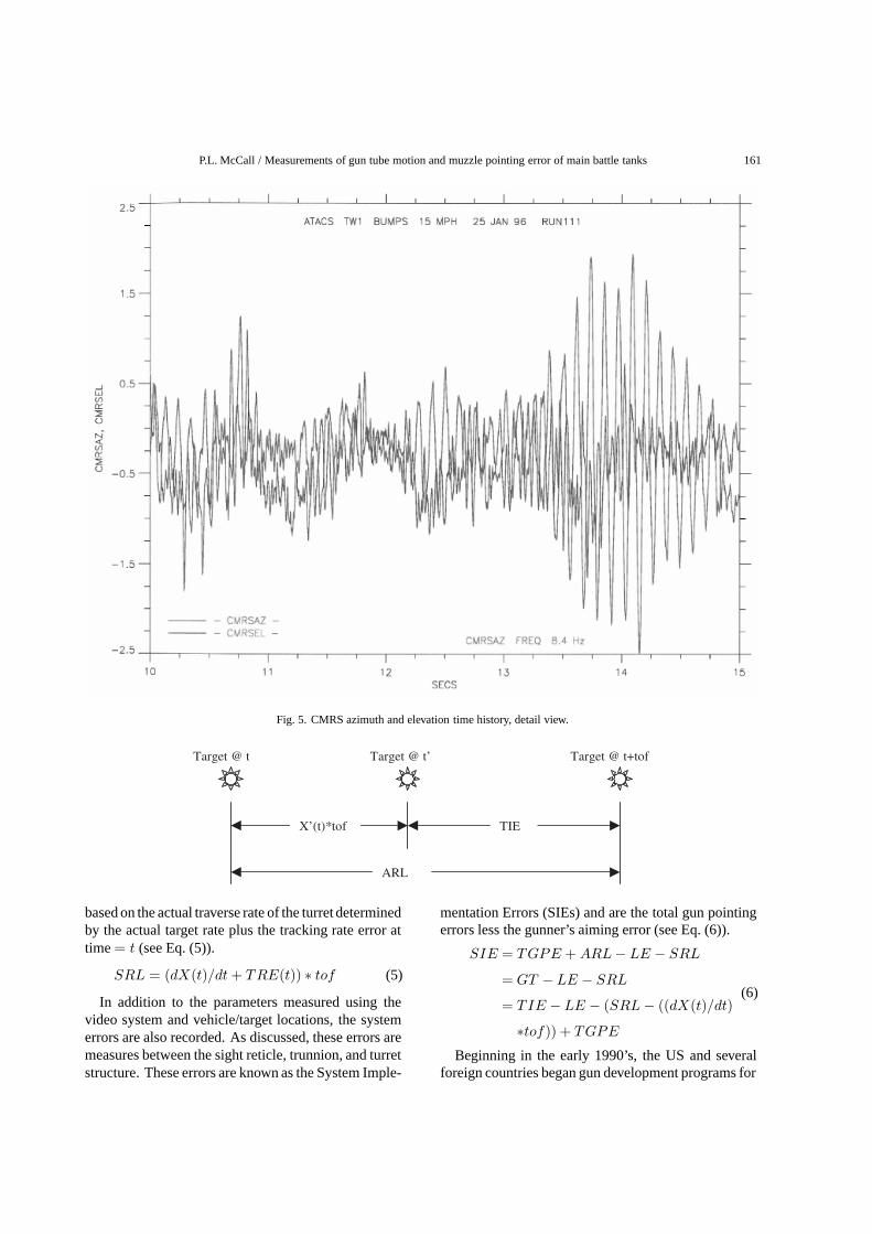
Fig. 5. CMRS azimuth and elevation time history, detail view.
Target @ t Target @ t’ Target @ t+tof
X’(t)*tof TIE
ARL
based on the actual traverse rate of the turret determinedby the actual target rate plus the tracking rate error attime = t (see Eq. (5)).
SRL = (dX(t)/dt + TRE(t)) ∗ tof (5)
In addition to the parameters measured using thevideo system and vehicle/target locations, the systemerrors are also recorded. As discussed, these errors aremeasures between the sight reticle, trunnion, and turretstructure. These errors are known as the System Imple-
mentation Errors (SIEs) and are the total gun pointingerrors less the gunner’s aiming error (see Eq. (6)).
SIE = TGPE + ARL − LE − SRL
= GT − LE − SRL(6)
= TIE − LE − (SRL − ((dX(t)/dt)
∗tof)) + TGPE
Beginning in the early 1990’s, the US and severalforeign countries began gun development programs for

162 P.L. McCall / Measurements of gun tube motion and muzzle pointing error of main battle tanks
Fig. 6. CMRS azimuth and elevation time history over RRC-9 bump course at 20 mph.
reticleTarget @ t’Target
X’(t) TRE
SRL/tof
their respective main battle tanks where the gun tube is4 to 5 feet longer than the current fielded gun systems.Testing of a longer gun system was conducted at ATCin a similar fashion as thus far described and paralleltests were conducted on the M1A1 tank. During non-firing tests, the SIEs were nominal and the tank ap-peared to be functioning efficiently. When firing actualammunition, hit probability results were poor and didnot reflect the nonfiring test results. Then, why werethe projectiles missing the target?
3. Automatic/continuous muzzle reference sensordevelopment
During the same period of time, ATC was assistingthe Army Research Laboratory in testing a ContinuousMuzzle Reference System (CMRS) built by PrincetonScientific Instruments under a Small Business Innova-tive Research (SBIR) contract [2]. The instrument thatwas developed is capable of continuous measurementof muzzle motion with a dynamic range of ±5 millira-dians and a precision of 5 microradians at a bandwidth

P.L. McCall / Measurements of gun tube motion and muzzle pointing error of main battle tanks 163
Fig. 7. CMRS azimuth and elevation time history, detail view.
Gun Tube ReferenceTarget @ t+tofTarget @ t
ARL TGPE
LE+SRL+SIE
of 1000 Hz. Testing had begun in November 1989 us-ing an M1A1 tank with the M256 gun. A second seriesof tests was conducted in March 1990. In 1993, ATCpurchased two units for gun dynamics measurements.One of these units was put to use on the prototype longgun program to help characterize the gun tube flexureand control problem.
The CMRS is an autocollimator-type instrumentwith a point light source (Light-Emitting Diode (LED))originating at the focus of a small diameter telescope
and a position detector also located in the focal plane.The LED source is collimated to form a parallel beamaimed to strike a mirror mounted to the muzzle. Thelight is reflected back to the telescope and is re-imagedon the position detector located in the focal plane (seeFig. 1). As the angle of the mirror changes, the focalpoint shifts on the detector. The mirror is rigidly fixedto the end of the muzzle and accurately follows thepointing angle of the last few feet of the tube relativeto the trunnion.

164 P.L. McCall / Measurements of gun tube motion and muzzle pointing error of main battle tanks
0 .0 0 0
0 .1 0 0
0 .2 0 0
0 .3 0 0
0 .4 0 0
0 .5 0 0
0 .6 0 0
0 .7 0 0
0 .8 0 0
5 1 0 15 20 25 30
V e hic le spe e d (mph)
ST
D (
mr
ad
s)
LONG
SHORT
M1A1#1
M1A1#2
Fig. 8. CMRS azimuth average standard deviations.
0 .000
0 .100
0 .200
0 .300
0 .400
0 .500
0 .600
0 .700
0 .800
0 .900
1 .000
5 10 15 20 25 30
V e hic le spe e d (mph)
ST
D (
mr
ad
s)
LONG
SHORT
M1A1#1
M1A1#2
Fig. 9. CMRS elevation, average standard deviations.
Figures 2 and 3 show the linearity of the transferfunctions of the detector in the elevation (y) and az-imuth (x) axes, respectively.
The use of the CMRS unit allows ATC to acquire gunflexure information on the gun and relate the muzzlepointing angle to the projectile miss distance. A sampleof the data collected is presented in Figs 4 through7 for a tank traveling at 15 mph and 20 mph over abump course. Figures 5 and 7 show a detailed viewof the section of time the tube goes into a resonance.From this information, the influence of the tube flexurebecomes evident. When the muzzle pointing angle wasadded to the total gun pointing error a correlation withthe impacts on target was observed. How does thiscompare to the M1A1 and the way delivery accuracy ismeasured?
4. Delivery accuracy characterization with respectto the muzzle
As discussed earlier in this paper, characterization ofthe delivery accuracy of a system was with respect to
the trunnion and relative to the line-of-sight. This alsoreflects the way the stabilization and gun control hadhistorically been implemented. As system specifica-tions become more stringent, requiring higher hit prob-abilities at extended ranges, greater terminal effects,faster firing platforms, etc., the influence of the dynam-ics of the tube becomes more critical. An increasedtube length simply amplifies the effect. To characterizethe influence of the tube flexure in delivery accuracy,information was collected for various control systemsand tube lengths for the prototype gun and also fortwo M1A1 production tanks. The standard deviationsof the gun tube flexure, as measured with the CMRSfor several test runs over the bump course at specifiedspeeds, were averaged and are presented in Figs 8 and9 for azimuth and elevation axes. Figures 10 and 11 de-pict the average of the standard deviations for azimuthand elevation position errors (the position errors are thevariations of the total gun pointing direction from theline of sight as described earlier in this paper) for thesame test runs depicted in Figs 8 and 9. A descrip-tion of the configurations depicted on the graphs is asfollows:

P.L. McCall / Measurements of gun tube motion and muzzle pointing error of main battle tanks 165
0 .0 0 0
0 .0 5 0
0 .1 0 0
0 .1 5 0
0 .2 0 0
0 .2 5 0
0 .3 0 0
0 .3 5 0
0 .4 0 0
0 .4 5 0
0 .5 0 0
5 1 0 1 5 2 0 2 5 3 0
V e hic le S pe e d (mph )
ST
D(m
ra
ds
)
LONG
SHORT
M1A1#1
M1A1#2
Fig. 10. Azimuth position error.
0 .00 0
0 .05 0
0 .10 0
0 .15 0
0 .20 0
0 .25 0
0 .30 0
0 .35 0
0 .40 0
0 .45 0
5 1 0 1 5 2 0 2 5 3 0
V e hic le S pe e d (mph)
ST
D (
mr
ad
s)
LONG
SHORT
M1A1#1
M1A1#2
Fig. 11. Elevation position error.
LONG – Denotes a longer gun design with a stan-dard “M1A1 like” control system that does not utilizethe CMRS signal or any improved stabilization controldesign.
SHORT – Refers to a similar gun design as LONGabove, however, the tube was manufactured to the stan-dard length found in the production M1A1 tank.
M1A1#1 and #2 – Two M1A1 production tanks withinstrumentation added to collect the same parametersas measured on the prototype gun system.
To obtain a true gun pointing error, which reflects thedelivery accuracy of the weapon system, gun-pointingerrors need to be relative to the muzzle pointing direc-tion. In essence we are combining the muzzle bendingor flexure (depicted in Figs 8 and 9) with position errors(Figs 10 and 11). In this light, we need to define someadditional terms. The Muzzle Pointing Angle (MPA)is defined as the angle of the muzzle from the boresightalignment. The Total Muzzle Pointing Error (TMPE)would then be defined as:
TMPE = TGPE + MPA (7)
Particular attention must be paid to the sign conven-tion of the MPA and must be the same as TGPE.
The System Implementation Error with respect to theMuzzle (SIEm) would then be as follows:
SIEm = TMPE + ARL − LE − SRL (8)
5. Conclusions
Fire control design is now taking into account thetube dynamics to improve delivery accuracy. To mea-sure system accuracy in a non-firing environment orduring actual weapon firing, errors must be referencedto the muzzle to determine the performance of thesedesigns. Determining pointing errors with respect tothe muzzle rather than the trunnion is only the begin-ning in relating impacts to where the muzzle of the gunis pointing. Testing has shown that the shape of the

166 P.L. McCall / Measurements of gun tube motion and muzzle pointing error of main battle tanks
tube as the projectile travels down the bore influencesthe jump of the projectile. The velocity component ofthe tube as it is flexing and translating imparts an addi-tional vector to the equation. Predictive algorithms arebeing used to determine when to allow the cartridge tofire and must be part of the error analysis. Additionalresearch needs to be done in these areas as well as inthe cross-coupling effect that is seen when you reducethe flexure in one axis only to have the flexure in theother axis increase. I guess it is safe to say that the
story does not end here . . .
References
[1] P.L. McCall, Proof Of Principle Demonstration of the AdvancedTank Cannon System, ATC-7994, Aberdeen Test Center, Ab-erdeen Proving Ground, MD, 1997.
[2] P.B. Karcher and A.D. Cope, Continuous Muzzle ReferenceSystem (CMRS), BRL-CR-643, Army Research Lab, AberdeenProving Ground, MD, 1990.

International Journal of
AerospaceEngineeringHindawi Publishing Corporationhttp://www.hindawi.com Volume 2010
RoboticsJournal of
Hindawi Publishing Corporationhttp://www.hindawi.com Volume 2014
Hindawi Publishing Corporationhttp://www.hindawi.com Volume 2014
Active and Passive Electronic Components
Control Scienceand Engineering
Journal of
Hindawi Publishing Corporationhttp://www.hindawi.com Volume 2014
International Journal of
RotatingMachinery
Hindawi Publishing Corporationhttp://www.hindawi.com Volume 2014
Hindawi Publishing Corporation http://www.hindawi.com
Journal ofEngineeringVolume 2014
Submit your manuscripts athttp://www.hindawi.com
VLSI Design
Hindawi Publishing Corporationhttp://www.hindawi.com Volume 2014
Hindawi Publishing Corporationhttp://www.hindawi.com Volume 2014
Shock and Vibration
Hindawi Publishing Corporationhttp://www.hindawi.com Volume 2014
Civil EngineeringAdvances in
Acoustics and VibrationAdvances in
Hindawi Publishing Corporationhttp://www.hindawi.com Volume 2014
Hindawi Publishing Corporationhttp://www.hindawi.com Volume 2014
Electrical and Computer Engineering
Journal of
Advances inOptoElectronics
Hindawi Publishing Corporation http://www.hindawi.com
Volume 2014
The Scientific World JournalHindawi Publishing Corporation http://www.hindawi.com Volume 2014
SensorsJournal of
Hindawi Publishing Corporationhttp://www.hindawi.com Volume 2014
Modelling & Simulation in EngineeringHindawi Publishing Corporation http://www.hindawi.com Volume 2014
Hindawi Publishing Corporationhttp://www.hindawi.com Volume 2014
Chemical EngineeringInternational Journal of Antennas and
Propagation
International Journal of
Hindawi Publishing Corporationhttp://www.hindawi.com Volume 2014
Hindawi Publishing Corporationhttp://www.hindawi.com Volume 2014
Navigation and Observation
International Journal of
Hindawi Publishing Corporationhttp://www.hindawi.com Volume 2014
DistributedSensor Networks
International Journal of