Measurement of Chokes made using type 31 material cores of Chokes made using type 3… ·...
33
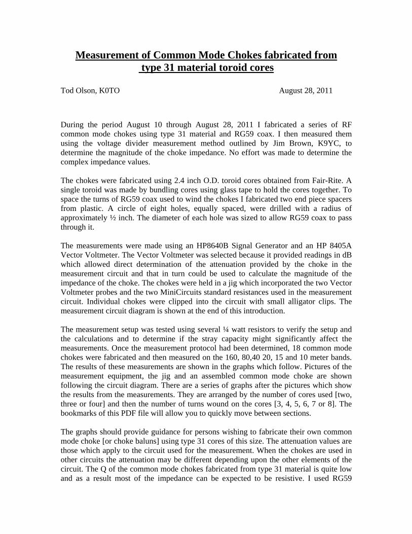
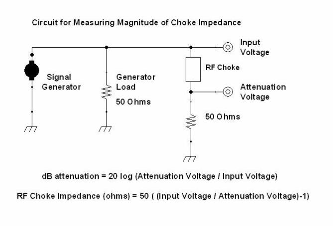
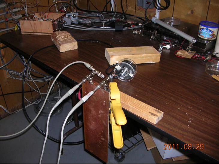
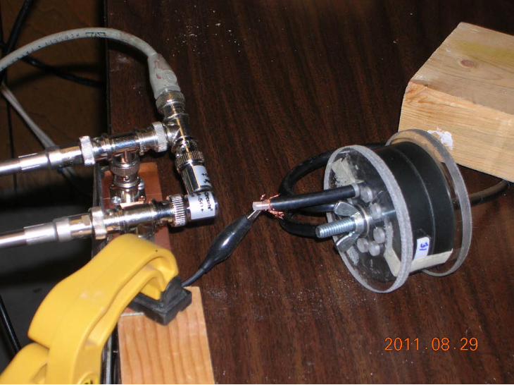
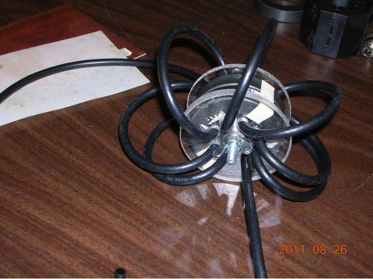
Measurement of Common Mode Chokes fabricated from type 31 material toroid cores Tod Olson, K0TO August 28, 2011 During the period August 10 through August 28, 2011 I fabricated a series of RF common mode chokes using type 31 material and RG59 coax. I then measured them using the voltage divider measurement method outlined by Jim Brown, K9YC, to determine the magnitude of the choke impedance. No effort was made to determine the complex impedance values. The chokes were fabricated using 2.4 inch O.D. toroid cores obtained from Fair-Rite. A single toroid was made by bundling cores using glass tape to hold the cores together. To space the turns of RG59 coax used to wind the chokes I fabricated two end piece spacers from plastic. A circle of eight holes, equally spaced, were drilled with a radius of approximately ½ inch. The diameter of each hole was sized to allow RG59 coax to pass through it. The measurements were made using an HP8640B Signal Generator and an HP 8405A Vector Voltmeter. The Vector Voltmeter was selected because it provided readings in dB which allowed direct determination of the attenuation provided by the choke in the measurement circuit and that in turn could be used to calculate the magnitude of the impedance of the choke. The chokes were held in a jig which incorporated the two Vector Voltmeter probes and the two MiniCircuits standard resistances used in the measurement circuit. Individual chokes were clipped into the circuit with small alligator clips. The measurement circuit diagram is shown at the end of this introduction. The measurement setup was tested using several ¼ watt resistors to verify the setup and the calculations and to determine if the stray capacity might significantly affect the measurements. Once the measurement protocol had been determined, 18 common mode chokes were fabricated and then measured on the 160, 80,40 20, 15 and 10 meter bands. The results of these measurements are shown in the graphs which follow. Pictures of the measurement equipment, the jig and an assembled common mode choke are shown following the circuit diagram. There are a series of graphs after the pictures which show the results from the measurements. They are arranged by the number of cores used [two, three or four] and then the number of turns wound on the cores [3, 4, 5, 6, 7 or 8]. The bookmarks of this PDF file will allow you to quickly move between sections. The graphs should provide guidance for persons wishing to fabricate their own common mode choke [or choke baluns] using type 31 cores of this size. The attenuation values are those which apply to the circuit used for the measurement. When the chokes are used in other circuits the attenuation may be different depending upon the other elements of the circuit. The Q of the common mode chokes fabricated from type 31 material is quite low and as a result most of the impedance can be expected to be resistive. I used RG59
Transcript of Measurement of Chokes made using type 31 material cores of Chokes made using type 3… ·...
Measurement of Common Mode Chokes fabricated from type 31 material toroid cores
Tod Olson, K0TO August 28, 2011
During the period August 10 through August 28, 2011 I fabricated a series of RF common mode chokes using type 31 material and RG59 coax. I then measured them using the voltage divider measurement method outlined by Jim Brown, K9YC, to determine the magnitude of the choke impedance. No effort was made to determine the complex impedance values. The chokes were fabricated using 2.4 inch O.D. toroid cores obtained from Fair-Rite. A single toroid was made by bundling cores using glass tape to hold the cores together. To space the turns of RG59 coax used to wind the chokes I fabricated two end piece spacers from plastic. A circle of eight holes, equally spaced, were drilled with a radius of approximately ½ inch. The diameter of each hole was sized to allow RG59 coax to pass through it. The measurements were made using an HP8640B Signal Generator and an HP 8405A Vector Voltmeter. The Vector Voltmeter was selected because it provided readings in dB which allowed direct determination of the attenuation provided by the choke in the measurement circuit and that in turn could be used to calculate the magnitude of the impedance of the choke. The chokes were held in a jig which incorporated the two Vector Voltmeter probes and the two MiniCircuits standard resistances used in the measurement circuit. Individual chokes were clipped into the circuit with small alligator clips. The measurement circuit diagram is shown at the end of this introduction. The measurement setup was tested using several ¼ watt resistors to verify the setup and the calculations and to determine if the stray capacity might significantly affect the measurements. Once the measurement protocol had been determined, 18 common mode chokes were fabricated and then measured on the 160, 80,40 20, 15 and 10 meter bands. The results of these measurements are shown in the graphs which follow. Pictures of the measurement equipment, the jig and an assembled common mode choke are shown following the circuit diagram. There are a series of graphs after the pictures which show the results from the measurements. They are arranged by the number of cores used [two, three or four] and then the number of turns wound on the cores [3, 4, 5, 6, 7 or 8]. The bookmarks of this PDF file will allow you to quickly move between sections. The graphs should provide guidance for persons wishing to fabricate their own common mode choke [or choke baluns] using type 31 cores of this size. The attenuation values are those which apply to the circuit used for the measurement. When the chokes are used in other circuits the attenuation may be different depending upon the other elements of the circuit. The Q of the common mode chokes fabricated from type 31 material is quite low and as a result most of the impedance can be expected to be resistive. I used RG59

because I had a supply and it is similar in size to the RG400U that I use for chokes for my amateur station. The RG400U allows one to use 1.5 KW transmitted power without problems if the SWR values are reasonable [ less than 4:1 or so ].
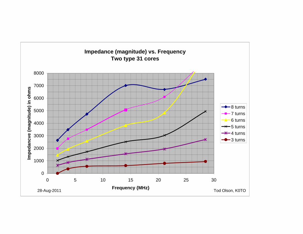
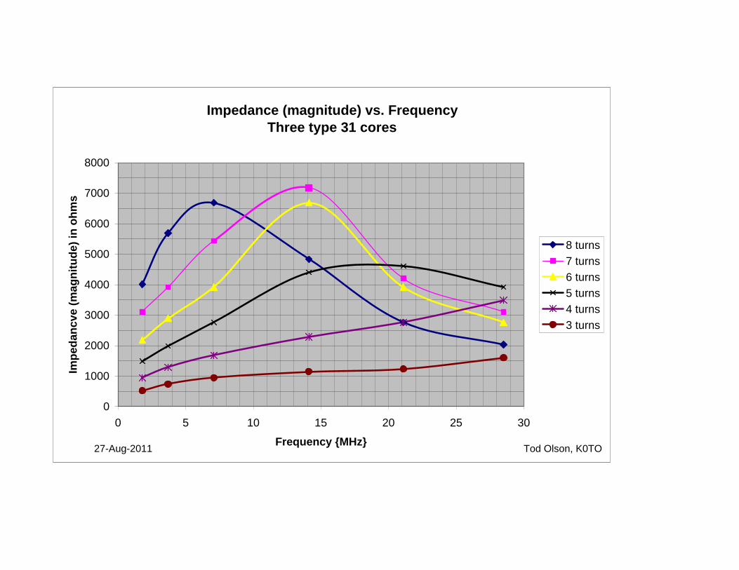
Impedance (magnitude) vs. FrequencyTwo type 31 cores
0
1000
2000
3000
4000
5000
6000
7000
8000
0 5 10 15 20 25 30
Frequency {MHz}
Impe
danc
ve (m
agni
tude
) in
ohm
s
8 turns7 turns6 turns5 turns4 turns3 turns
Tod Olson, K0TO28-Aug-2011
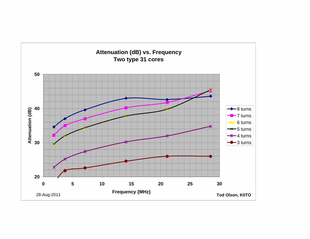
Attenuation (dB) vs. FrequencyTwo type 31 cores
20
30
40
50
0 5 10 15 20 25 30Frequency {MHz}
Atte
nuat
ion
(dB
) 8 turns7 turns6 turns5 turns4 turns3 turns
Tod Olson, K0TO28-Aug-2011
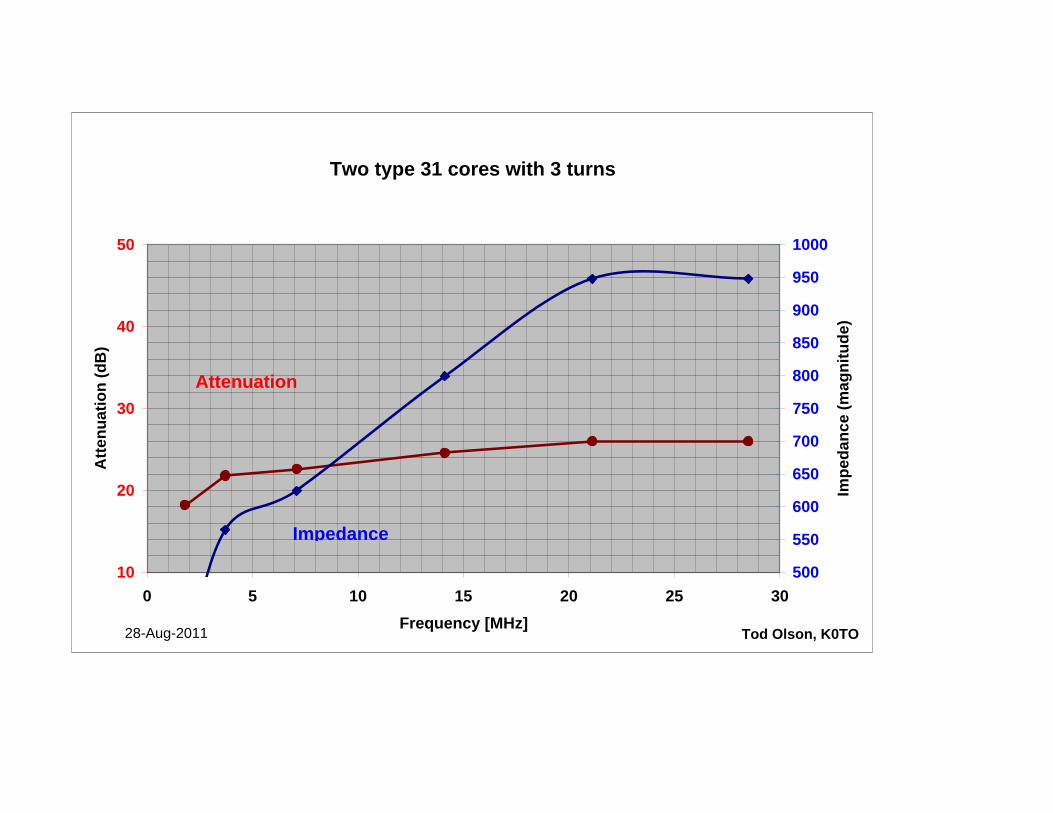
Two type 31 cores with 3 turns
10
20
30
40
50
0 5 10 15 20 25 30Frequency [MHz]
Atte
nuat
ion
(dB
)
500
550
600
650
700
750
800
850
900
950
1000
Impe
danc
e (m
agni
tude
)
Tod Olson, K0TO28-Aug-2011
Attenuation
Impedance
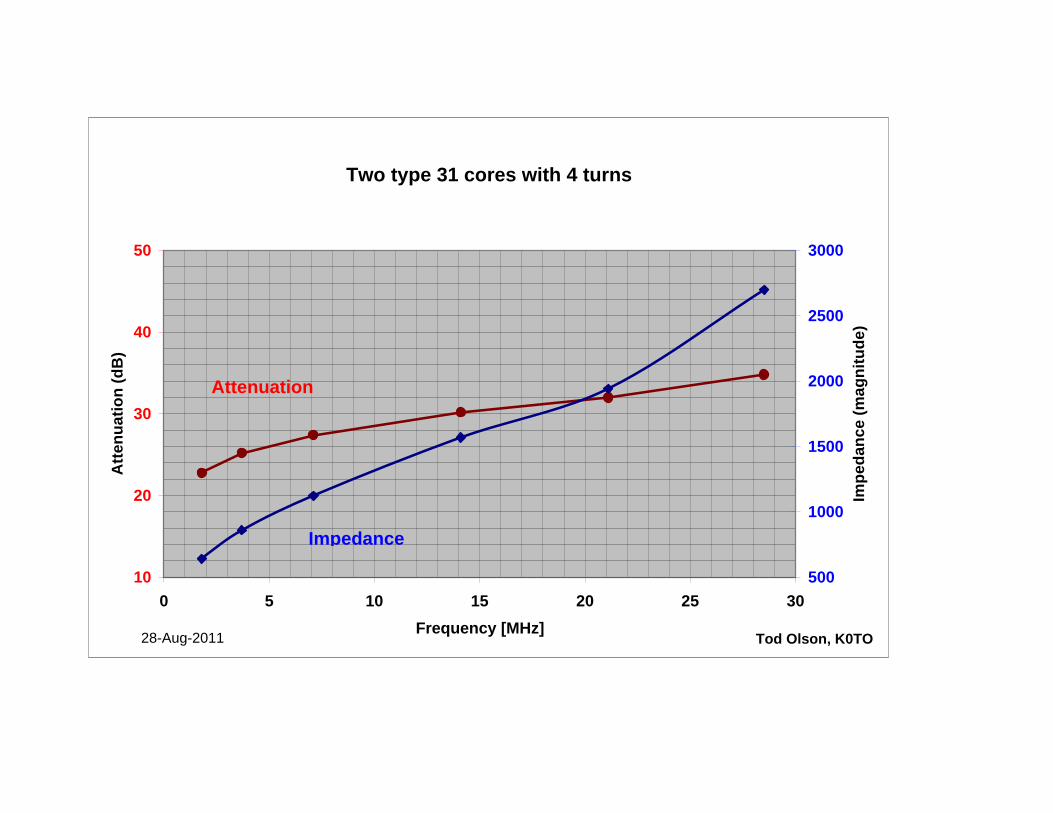
Two type 31 cores with 4 turns
10
20
30
40
50
0 5 10 15 20 25 30Frequency [MHz]
Atte
nuat
ion
(dB
)
500
1000
1500
2000
2500
3000
Impe
danc
e (m
agni
tude
)
Tod Olson, K0TO28-Aug-2011
Attenuation
Impedance
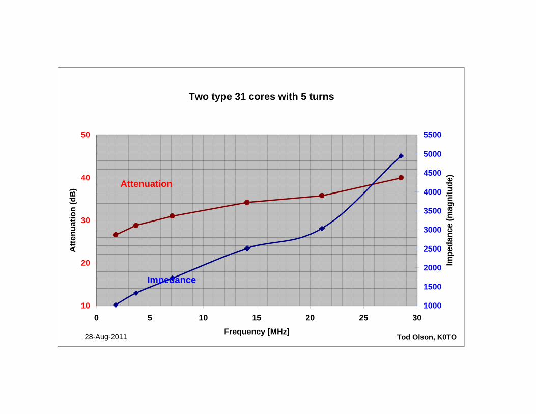
Two type 31 cores with 5 turns
10
20
30
40
50
0 5 10 15 20 25 30Frequency [MHz]
Atte
nuat
ion
(dB
)
1000
1500
2000
2500
3000
3500
4000
4500
5000
5500
Impe
danc
e (m
agni
tude
)
Tod Olson, K0TO28-Aug-2011
Attenuation
Impedance
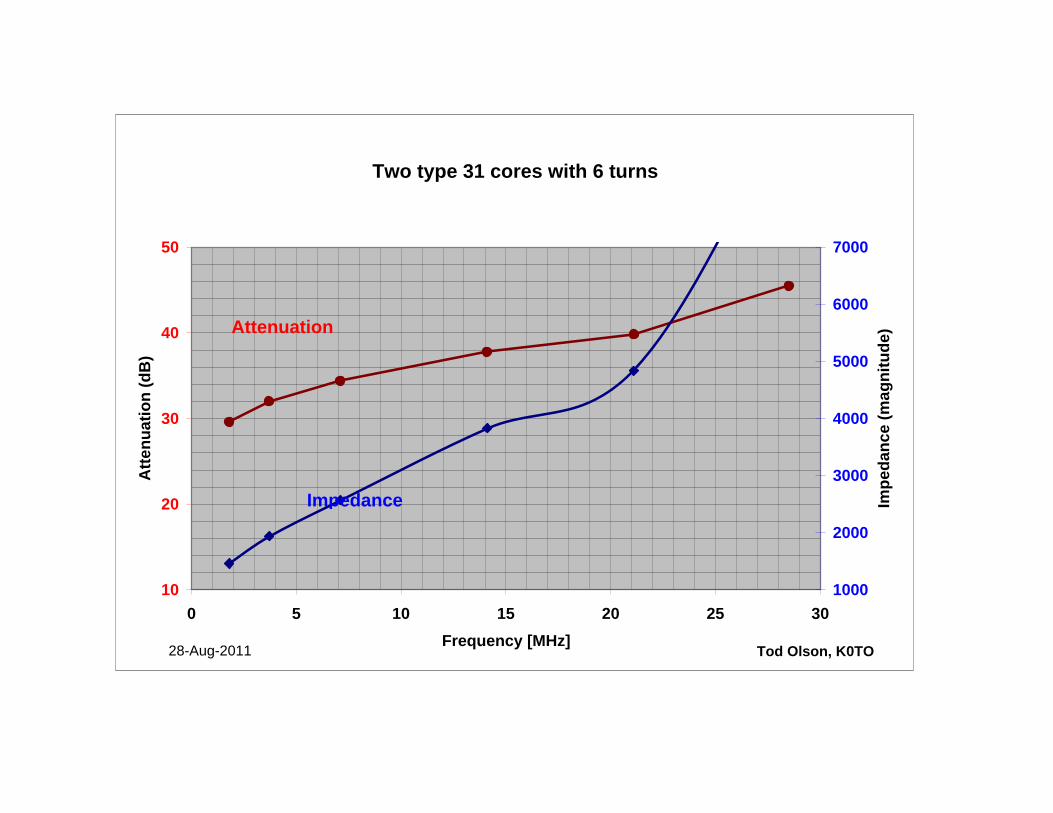
Two type 31 cores with 6 turns
10
20
30
40
50
0 5 10 15 20 25 30Frequency [MHz]
Atte
nuat
ion
(dB
)
1000
2000
3000
4000
5000
6000
7000
Impe
danc
e (m
agni
tude
)
Tod Olson, K0TO28-Aug-2011
Attenuation
Impedance
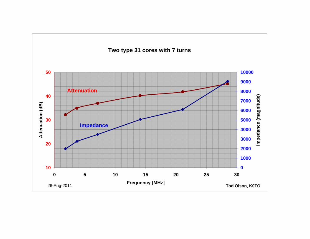
Two type 31 cores with 7 turns
10
20
30
40
50
0 5 10 15 20 25 30Frequency [MHz]
Atte
nuat
ion
(dB
)
0
1000
2000
3000
4000
5000
6000
7000
8000
9000
10000
Impe
danc
e (m
agni
tude
)
Tod Olson, K0TO28-Aug-2011
Attenuation
Impedance
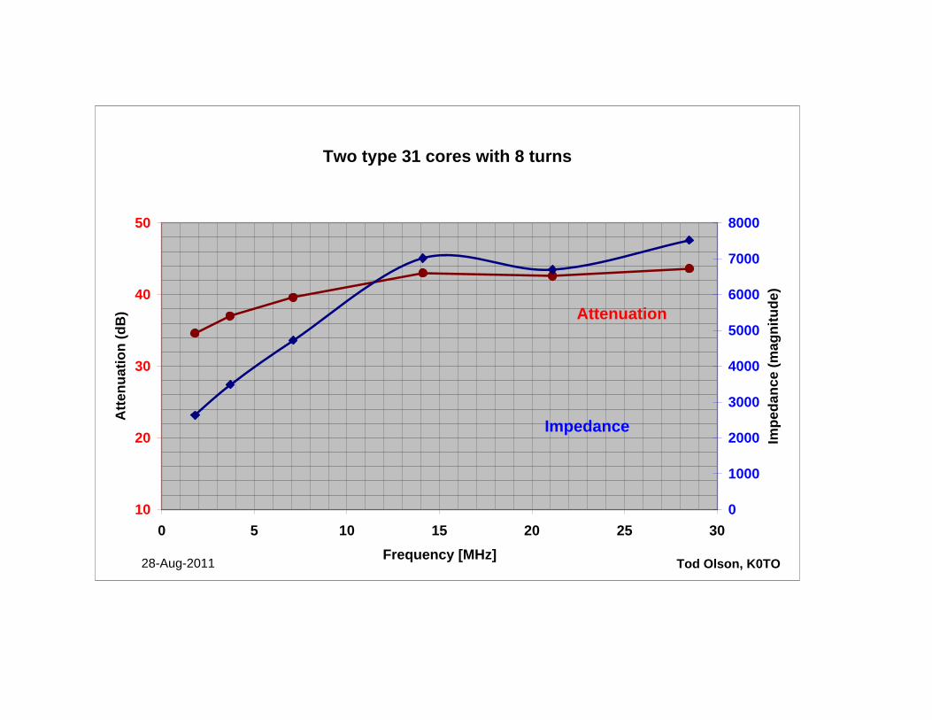
Two type 31 cores with 8 turns
10
20
30
40
50
0 5 10 15 20 25 30Frequency [MHz]
Atte
nuat
ion
(dB
)
0
1000
2000
3000
4000
5000
6000
7000
8000
Impe
danc
e (m
agni
tude
)
Tod Olson, K0TO28-Aug-2011
Impedance
Attenuation
Impedance (magnitude) vs. FrequencyThree type 31 cores
0
1000
2000
3000
4000
5000
6000
7000
8000
0 5 10 15 20 25 30
Frequency {MHz}
Impe
danc
ve (m
agni
tude
) in
ohm
s
8 turns7 turns6 turns5 turns4 turns3 turns
Tod Olson, K0TO27-Aug-2011
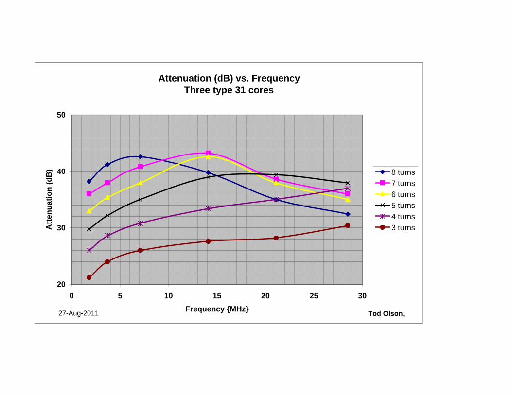
Attenuation (dB) vs. FrequencyThree type 31 cores
20
30
40
50
0 5 10 15 20 25 30Frequency {MHz}
Atte
nuat
ion
(dB
) 8 turns7 turns6 turns5 turns4 turns3 turns
Tod Olson, 27-Aug-2011
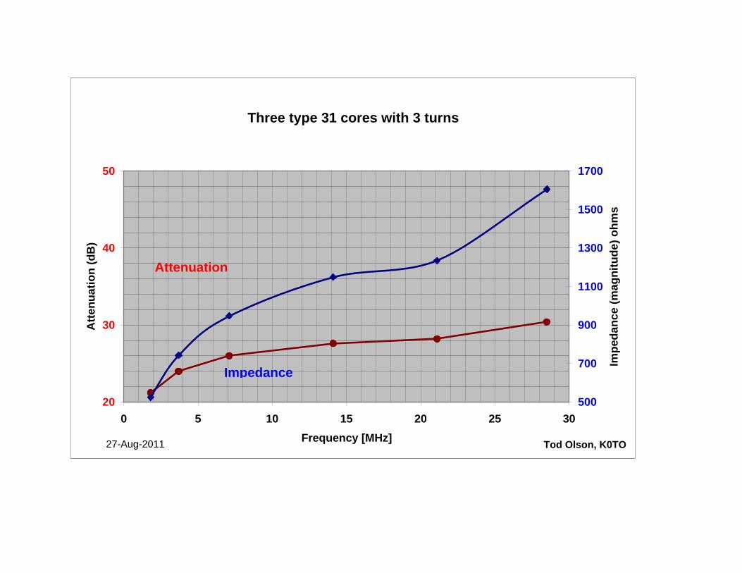
Three type 31 cores with 3 turns
20
30
40
50
0 5 10 15 20 25 30Frequency [MHz]
Atte
nuat
ion
(dB
)
500
700
900
1100
1300
1500
1700
Impe
danc
e (m
agni
tude
) ohm
s
Tod Olson, K0TO27-Aug-2011
Attenuation
Impedance
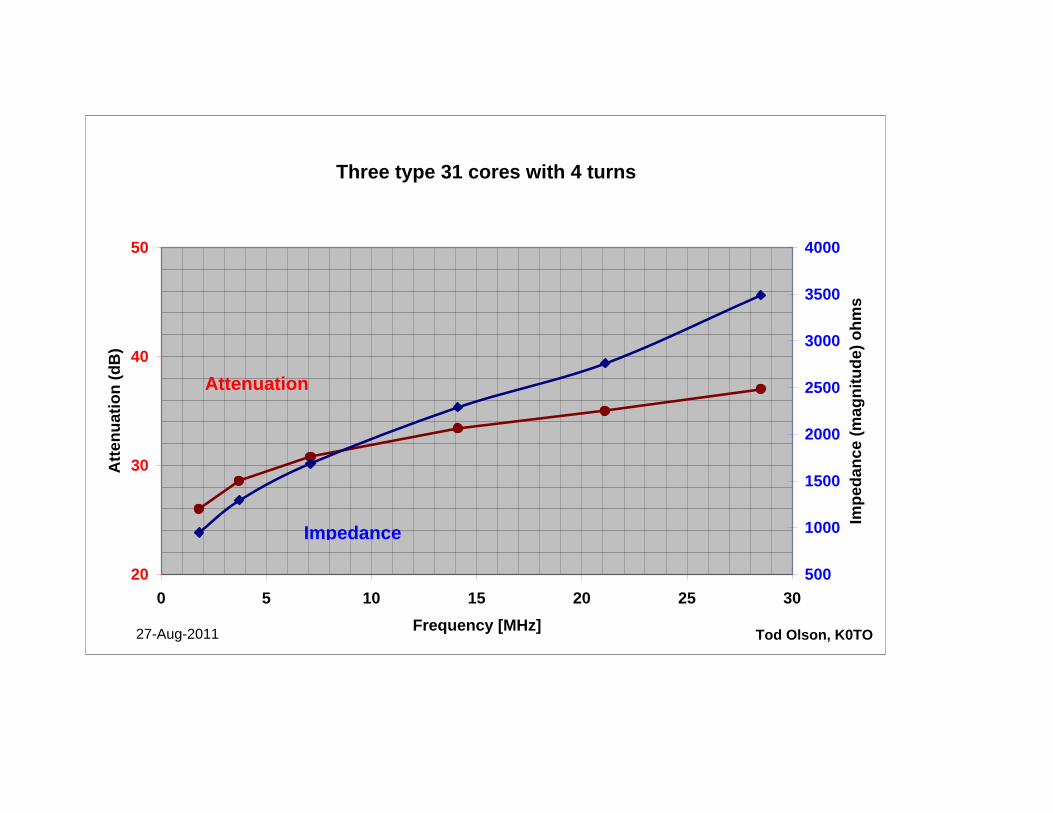
Three type 31 cores with 4 turns
20
30
40
50
0 5 10 15 20 25 30Frequency [MHz]
Atte
nuat
ion
(dB
)
500
1000
1500
2000
2500
3000
3500
4000
Impe
danc
e (m
agni
tude
) ohm
s
Tod Olson, K0TO27-Aug-2011
Attenuation
Impedance
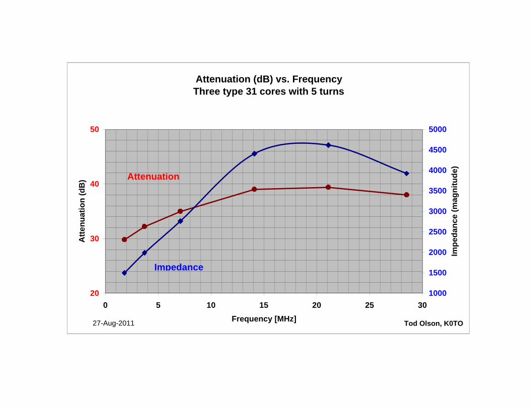
Attenuation (dB) vs. FrequencyThree type 31 cores with 5 turns
20
30
40
50
0 5 10 15 20 25 30Frequency [MHz]
Atte
nuat
ion
(dB
)
1000
1500
2000
2500
3000
3500
4000
4500
5000
Impe
danc
e (m
agni
tude
)
Tod Olson, K0TO27-Aug-2011
Attenuation
Impedance
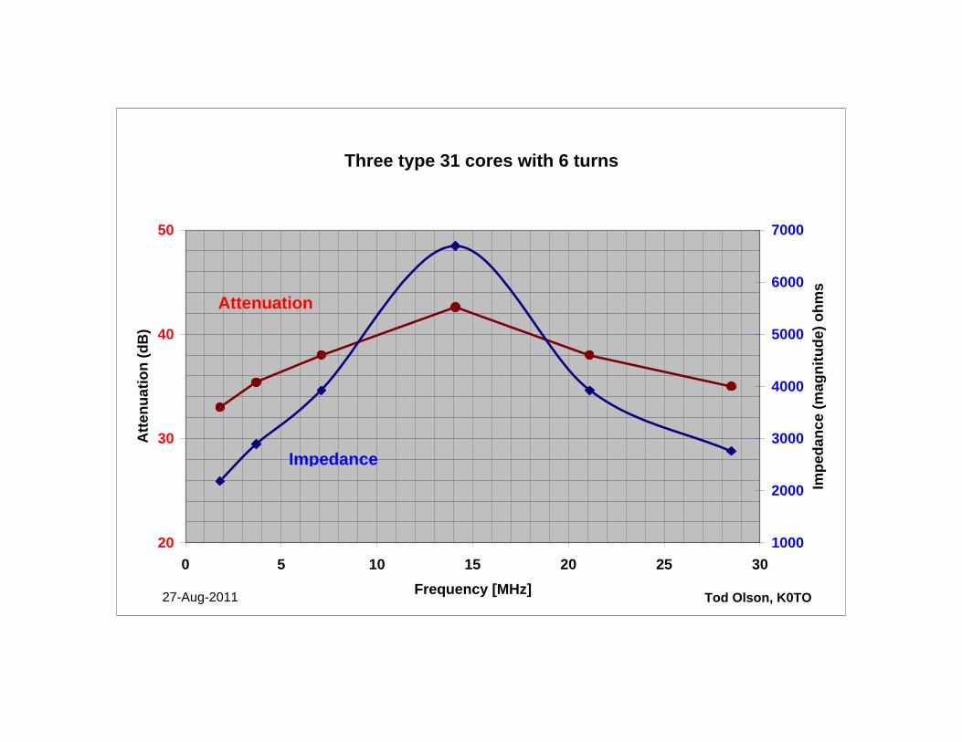
Three type 31 cores with 6 turns
20
30
40
50
0 5 10 15 20 25 30Frequency [MHz]
Atte
nuat
ion
(dB
)
1000
2000
3000
4000
5000
6000
7000
Impe
danc
e (m
agni
tude
) ohm
s
Tod Olson, K0TO27-Aug-2011
Attenuation
Impedance
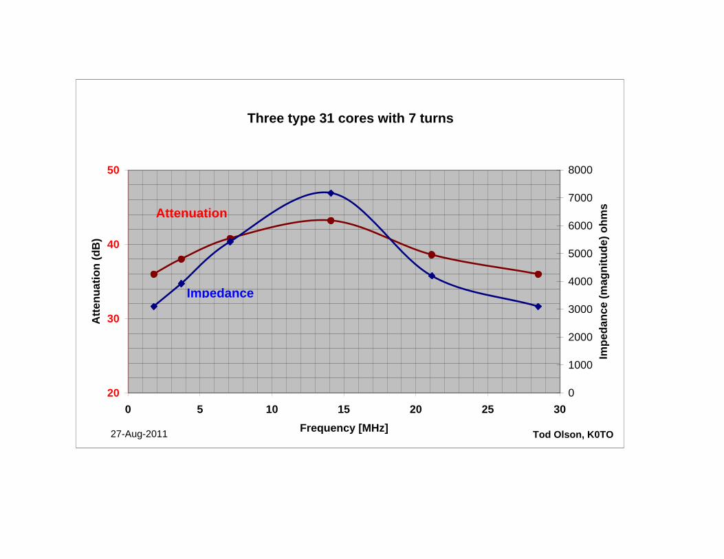
Three type 31 cores with 7 turns
20
30
40
50
0 5 10 15 20 25 30Frequency [MHz]
Atte
nuat
ion
(dB
)
0
1000
2000
3000
4000
5000
6000
7000
8000
Impe
danc
e (m
agni
tude
) ohm
s
Tod Olson, K0TO27-Aug-2011
Attenuation
Impedance
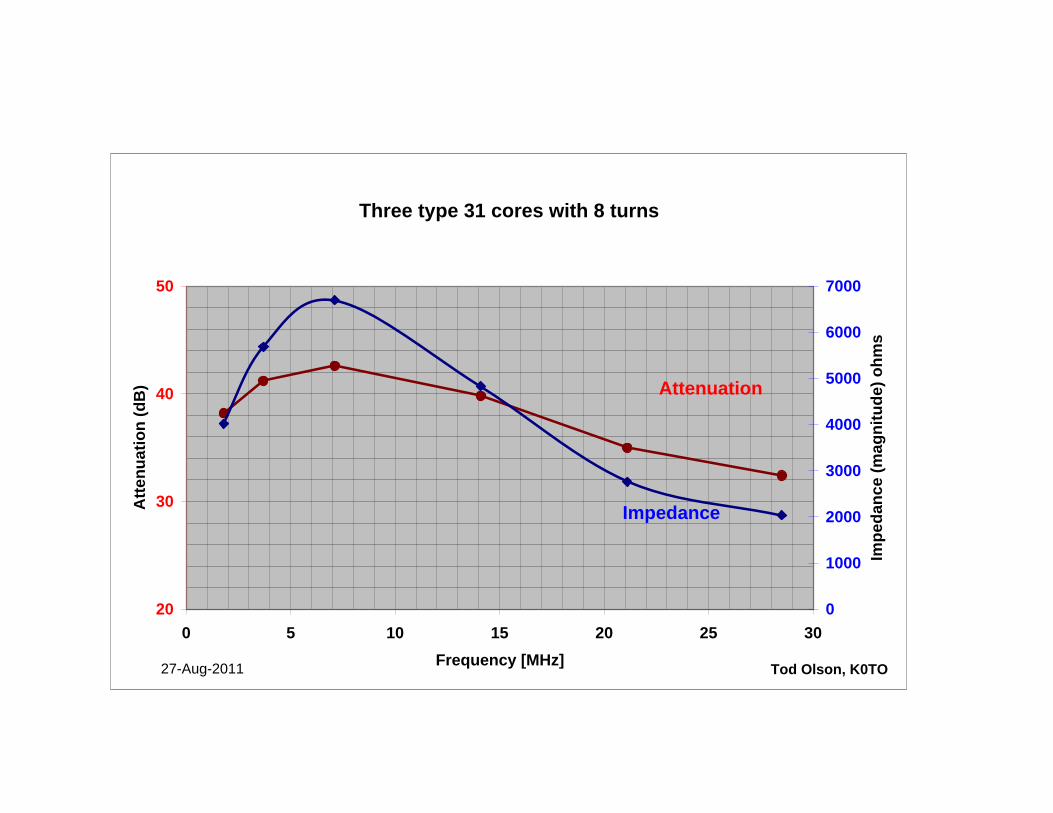
Three type 31 cores with 8 turns
20
30
40
50
0 5 10 15 20 25 30Frequency [MHz]
Atte
nuat
ion
(dB
)
0
1000
2000
3000
4000
5000
6000
7000
Impe
danc
e (m
agni
tude
) ohm
s
Tod Olson, K0TO27-Aug-2011
Impedance
Attenuation
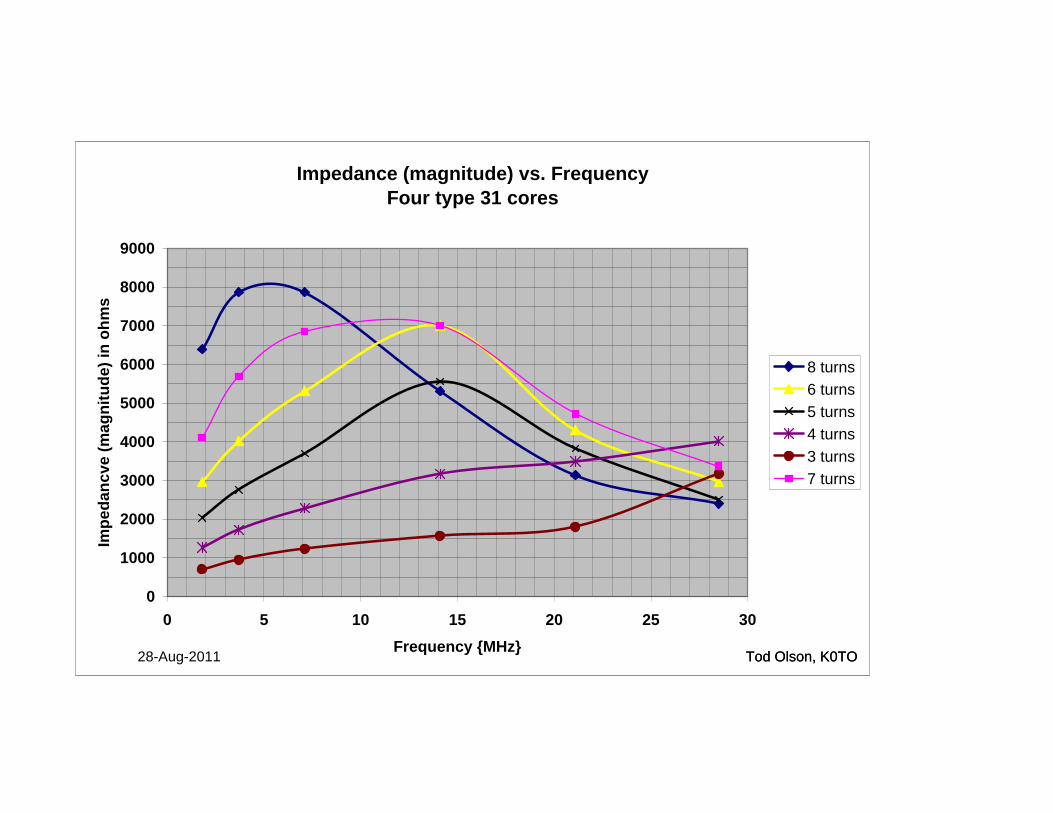
Impedance (magnitude) vs. FrequencyFour type 31 cores
0
1000
2000
3000
4000
5000
6000
7000
8000
9000
0 5 10 15 20 25 30Frequency {MHz}
Impe
danc
ve (m
agni
tude
) in
ohm
s
8 turns6 turns5 turns4 turns3 turns7 turns
Tod Olson, K0TO28-Aug-2011 Tod Olson, K0TO
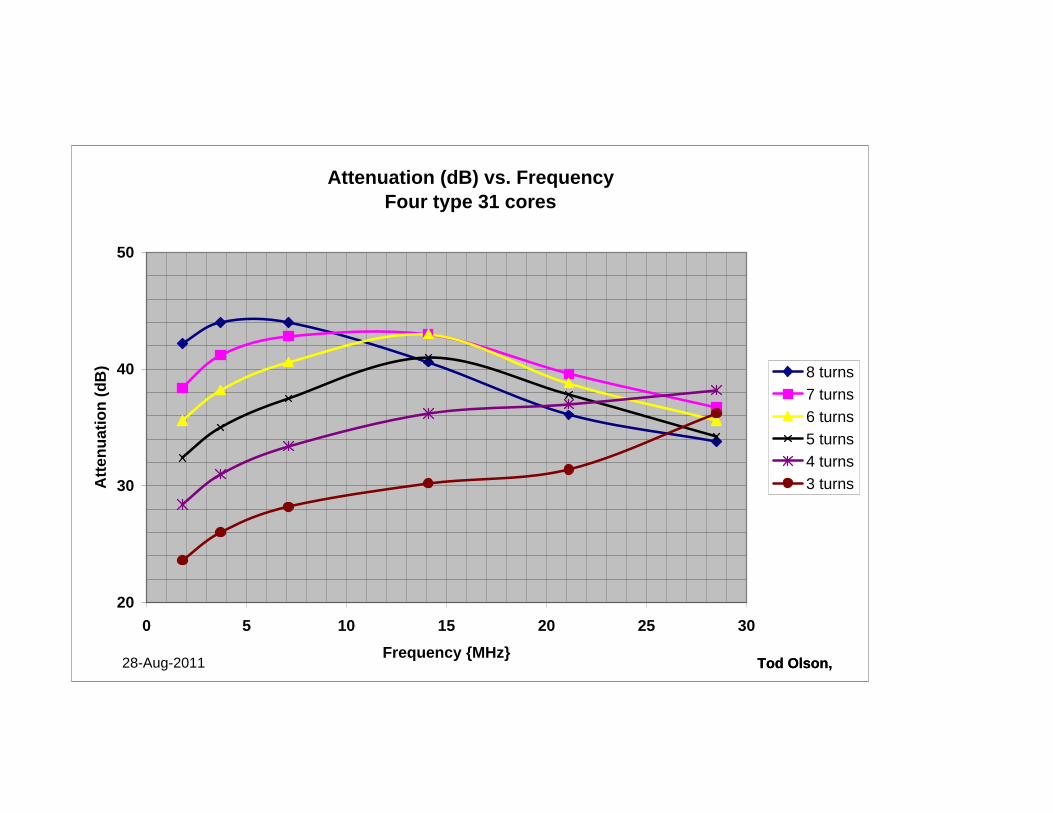
Attenuation (dB) vs. FrequencyFour type 31 cores
20
30
40
50
0 5 10 15 20 25 30Frequency {MHz}
Atte
nuat
ion
(dB
) 8 turns7 turns6 turns5 turns4 turns3 turns
Tod Olson, Tod Olson, 28-Aug-2011
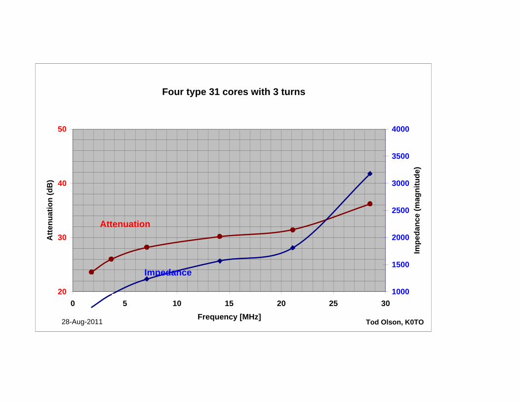
Four type 31 cores with 3 turns
20
30
40
50
0 5 10 15 20 25 30Frequency [MHz]
Atte
nuat
ion
(dB
)
1000
1500
2000
2500
3000
3500
4000
Impe
danc
e (m
agni
tude
)
Tod Olson, K0TO28-Aug-2011
Attenuation
Impedance
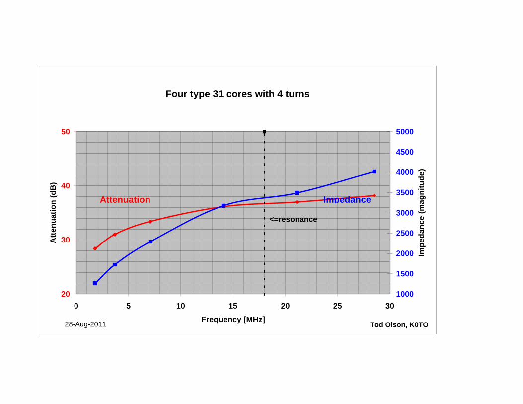
Four type 31 cores with 4 turns
20
30
40
50
0 5 10 15 20 25 30Frequency [MHz]
Atte
nuat
ion
(dB
)
1000
1500
2000
2500
3000
3500
4000
4500
5000
Impe
danc
e (m
agni
tude
)
Tod Olson, K0TO28-Aug-2011
Attenuation Impedance
<=resonance
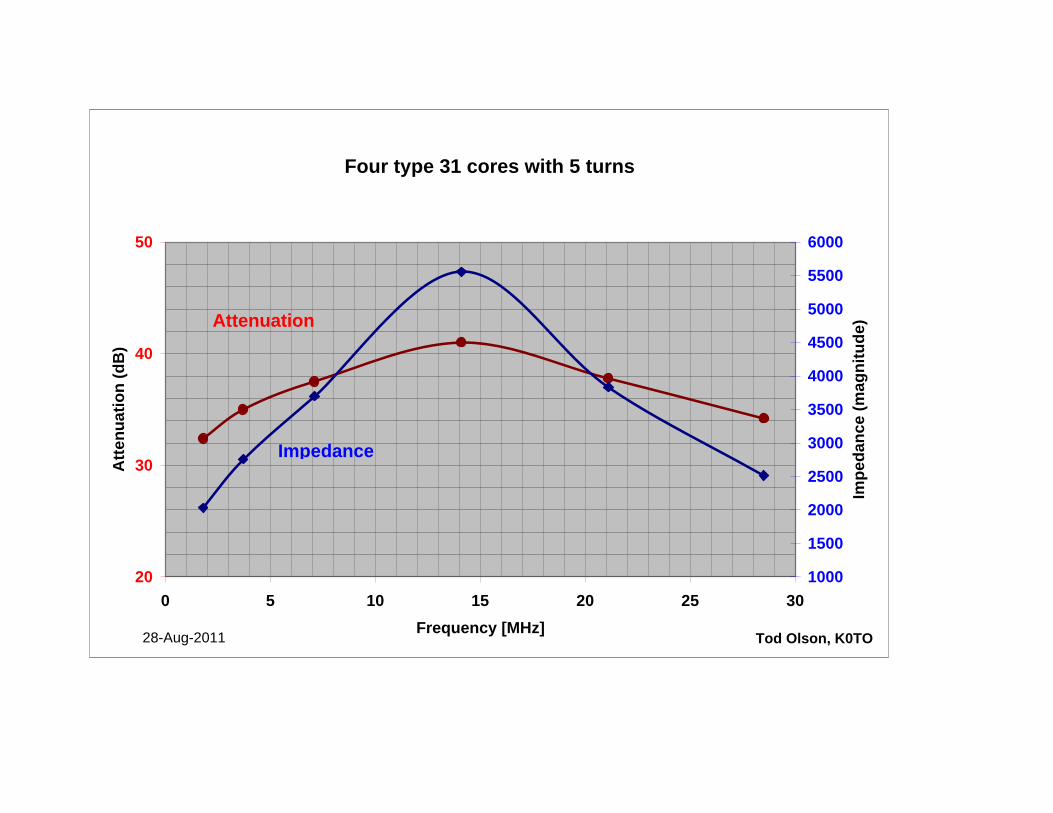
Four type 31 cores with 5 turns
20
30
40
50
0 5 10 15 20 25 30Frequency [MHz]
Atte
nuat
ion
(dB
)
1000
1500
2000
2500
3000
3500
4000
4500
5000
5500
6000
Impe
danc
e (m
agni
tude
)
Tod Olson, K0TO28-Aug-2011
Attenuation
Impedance
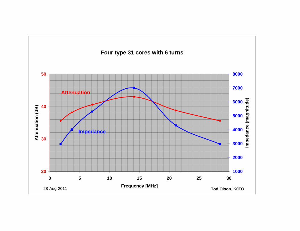
Four type 31 cores with 6 turns
20
30
40
50
0 5 10 15 20 25 30Frequency [MHz]
Atte
nuat
ion
(dB
)
1000
2000
3000
4000
5000
6000
7000
8000
Impe
danc
e (m
agni
tude
)
Tod Olson, K0TO28-Aug-2011
Attenuation
Impedance

Four type 31 cores with 7 turns
20
30
40
50
0 5 10 15 20 25 30Frequency [MHz]
Atte
nuat
ion
(dB
)
1000
2000
3000
4000
5000
6000
7000
8000
Impe
danc
e (m
agni
tude
)
28-Aug-201128-Aug-2011
Attenuation
Impedance
Tod Olson, K0TO
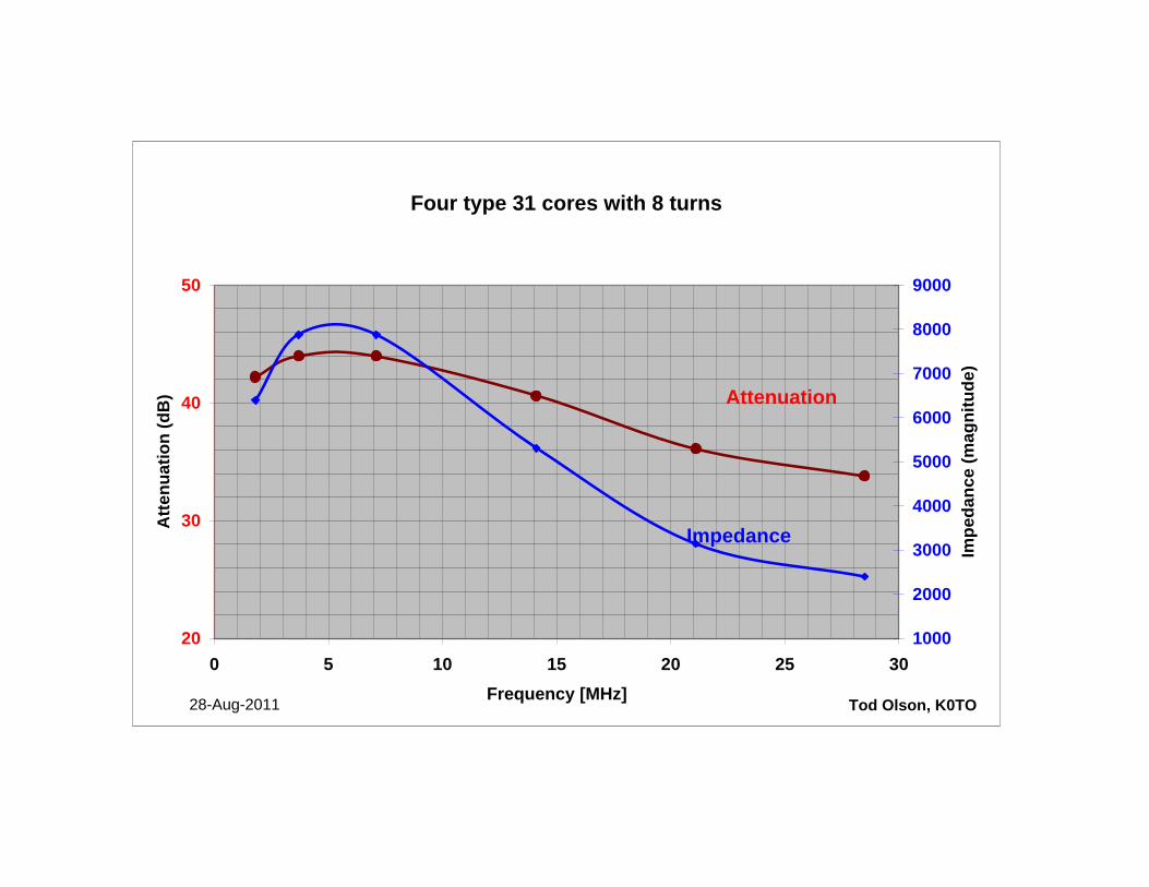
Four type 31 cores with 8 turns
20
30
40
50
0 5 10 15 20 25 30Frequency [MHz]
Atte
nuat
ion
(dB
)
1000
2000
3000
4000
5000
6000
7000
8000
9000
Impe
danc
e (m
agni
tude
)
Tod Olson, K0TO28-Aug-2011
Impedance
Attenuation
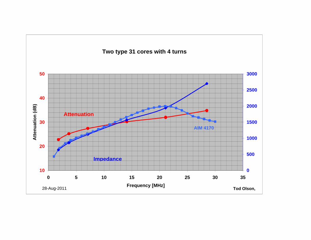
Two type 31 cores with 4 turns
10
20
30
40
50
0 5 10 15 20 25 30 35Frequency [MHz]
Atte
nuat
ion
(dB
)
0
500
1000
1500
2000
2500
3000
Tod Olson, 28-Aug-2011
Attenuation
Impedance
AIM 4170
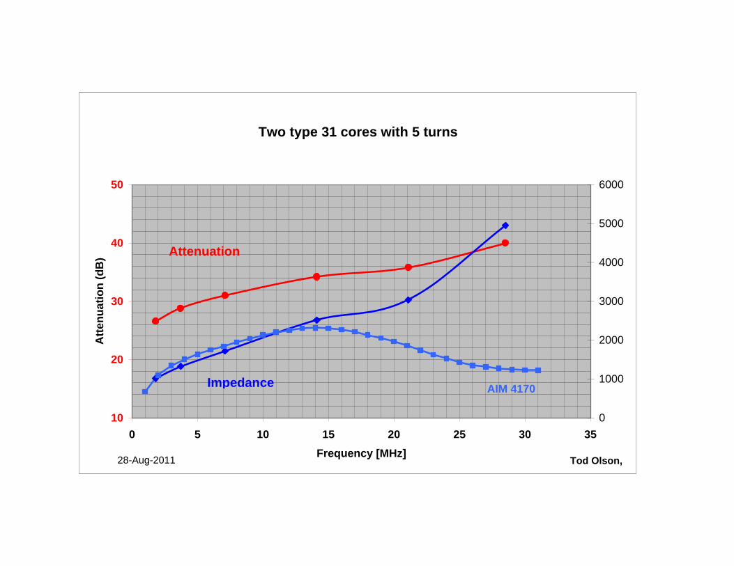
Two type 31 cores with 5 turns
10
20
30
40
50
0 5 10 15 20 25 30 35Frequency [MHz]
Atte
nuat
ion
(dB
)
0
1000
2000
3000
4000
5000
6000
Tod Olson, 28-Aug-2011
Attenuation
Impedance AIM 4170