Measurement of cesium-137 and cobalt-60 gamma radiation ... · Measurement of Cesium-137 and...
5
Journal of Resear ch of the National Bur eau of Standards Vol. 48, No.2, February 1952 Research Paper 2298 Measurement of Cesium-137 and Cobalt-60 Gamma Radiation With a Pressure Ionization Chamber G. R. Grove 1 The characteri stics of the pre ssure ionization chamber at the National Bureau of Stand- ards hav e been s tudied for the gamma radiation from a cesium-137 source (0.6614 Mev) and from a coba lt-60 source (1.1715 and 1.3316 Mev ). The dosage rates produced in air by these sources were measu red with this chamber with an accuracy of about 2 percent. Dosage rates obtained with an extrapolation chamber and a Victoreen thimble chamber agreed with the valu es meas ured by the pre ssure chamber within the limits of the experimental error s. 1. Introduction A study of the chara ctristics of the pressure ioni- zation chamber at the ational Bureau of Standards for X-rays up to 400 kv has been discussed by Taylor, Singer, and Ch arlton [1 ] 2. The resu lts of their study showed that it was possible to mea ure accurately the dosage rates of high-voltage X-rays in accordance with the international definition of the roentgen. Taylor and Singer [2 ] also used this chamber to measure the ionization of the gamma radiation from a radium source and determined a value for the emission constant of radium. At that time it was not feasible to investigate completely the cham her response with quantum energies in the million-volt region. Howev er, Taylor and Singer believed their measurements were accurate to within ± 0.4 percent. Radioactive materials of sufficient radioactivity in- tensity and particularl y suited for use with the pres- sure chamber have become available only recently. The study of the characteristics of the chamber with isotopes having gamma radiation in the energy re- gions of 0.6 and 1.3 Mev was undertaken to determine the reliability of the chamber for measuring the dosage rates produced by radiation energies up to 1.3 Mev. An extrapolation chamber and a Victoreen thimble chamber were also tested so that their readings could be compared with that of the pressure chamber. Cesium-137 and cobalt-60 isotopes were obtained from the Oak Ridge National Laboratory for use with the chamber . The cesium isotope emits a gamma ray of 0.6614 Mev [3], and cobalt-60 emits 2 quanta in cascade per disint egration with energies of 1.1715 and 1.3316 Mev [4]. The activities of the cesium and cobalt samples were about 8 and 1.5 curies, respectively. 2. Apparatus and Procedure 2.1. Pressure Cha mber The diaphragm system and chamber are shown chematically in figure 1. The source is housed in an aluminum cylin drical spool, which can be moved I Present address, Mound Laboratory, Miamis berg, Ob io. 2 Figures in brackets indicate the literature references at the end of th is paper. LEAD BACK SHIELD LEAD STRAY RADIATIO N BAFFLE FIGURE 1. Diaphragm system. axially inside a diameter aluminum tube to vary the distance between the diaphragm and the ource. The diameter of the aluminum tube is twice as large as the diameter of the diaphragm aperture and about three times as large as the diameters of the sources used. The aluminum tubing is sup- ported in contai ners that are filled with lead shot to reduce the radiation intensity in all directions ex- cept along the axis of the tube . A l ead wall across the back of the tubing confines the radiati on to a forward direction. The gamma-ray b eam defined by the diaphragm pas ses through an aluminum window 0.8 mm thick and 5.2 cm in diameter into the chamber . The cylindrical pressure chamber has an inside length of 7 ft and a diamet er of 30 in. Collecting electrodes are arranged in the chamber on a pair of rails in such a way that they can be moved from the outside along the axis of the tank over a range of about 125 cm. The spacing of the electrodes also can be smoothly adjusted from 7.2 em up to about 39 cm. These electrodes consist of aluminum plates 75 cm long and 40 cm in height . An insulated aluminum col- lecting plate 25.4 cm wide and 35 cm high is located at the center of the grounded electrode. The sec- tions of the grounded electrode aro und the collecting plate act as guard plates. Equal potential planes are provided in the sensitive ionization volume by means O.4-mm aluminum guard wires located in planes 14.7 I
Transcript of Measurement of cesium-137 and cobalt-60 gamma radiation ... · Measurement of Cesium-137 and...

Journal of Research of the National Bureau of Standards Vol. 48, No.2, February 1952 Research Paper 2298
Measurement of Cesium-137 and Cobalt-60 Gamma Radiation With a Pressure Ionization Chamber
G . R. Grove 1
The characteristics of the pressure ionization chamber at t he National Bureau of Standards have been studied for the gamma radiation from a cesium-137 sou rce (0.6614 Mev) and from a cobalt-60 source (1.1715 and 1.3316 Mev). The dosage rates produced in air by these sources were measured with this chamber with an accuracy of about 2 percent. Dosage rates obtained with an extrapolation chamber and a Victoreen thimble chamber agreed with the values measured by the pressure chamber within t he limits of the experimental errors.
1. Introduction
A study of the charactristics of the pressure ionization chamber at the ational Bureau of Standards for X-rays up to 400 kv has been discussed by Taylor, Singer, and Charlton [1]2. The results of their study showed that it was possible to mea ure accurately the dosage rates of high-voltage X-rays in accordance with the international definition of the roentgen. Taylor and Singer [2] also used this chamber to measure the ionization of the gamma radiation from a radium source and determined a value for the emission constant of radium. At that time it was not feasible to investigate completely the cham her response with quantum energies in the million-volt region. However, Taylor and Singer believed their measurements were accurate to within ± 0.4 percent.
Radioactive materials of sufficient radioactivity intensity and particularly suited for use with the pressure chamber have become available only recently. The study of the characteristics of the chamber with isotopes having gamma radiation in the energy regions of 0.6 and 1.3 Mev was undertaken to determine the reliability of the chamber for measuring the dosage rates produced by radiation energies up to 1.3 Mev. An extrapolation chamber and a Victoreen thimble chamber were also tested so that their readings could be compared with that of the pressure chamber.
Cesium-137 and cobalt-60 isotopes were obtained from the Oak Ridge National Laboratory for use with the chamber. The cesium isotope emits a gamma ray of 0.6614 Mev [3], and cobalt-60 emits 2 quanta in cascade per disintegration with energies of 1.1715 and 1.3316 Mev [4]. The activities of the cesium and cobalt samples were about 8 and 1.5 curies, respectively.
2 . Apparatus and Procedure
2.1. Pressure Cha mber
The diaphragm system and chamber are shown chematically in figure 1. The source is housed in an
aluminum cylindrical spool, which can be moved
I Present add ress, Mound Laboratory, Miamisberg, Ob io. 2 Figures in brackets indicate the literature references at the end of this paper.
LEAD BACK SHIELD
~ LEAD
STRAY RADIATION BAFFLE
FIGURE 1. Diaphragm system.
axially inside a l~-in . diameter aluminum tube to vary the distance between the diaphragm and the ource. The diameter of the aluminum tube is twice
as large as the diameter of the diaphragm aperture and about three times as large as the diameters of the so urces used. The aluminum tubing is supported in containers that are filled with lead shot to reduce the radiation intensity in all directions except along the axis of the tube. A lead wall across the back of the tubing confines the radiation to a forward direction.
The gamma-ray beam defined by the diaphragm passes through an aluminum window 0.8 mm thick and 5.2 cm in diameter into the chamber. The cylindrical pressure chamber has an inside length of 7 ft and a diameter of 30 in. Collecting electrodes are arranged in the chamber on a pair of rails in such a way that they can be moved from the outside along the axis of the tank over a range of about 125 cm. The spacing of the electrodes also can be smoothly adjusted from 7.2 em up to about 39 cm. These electrodes consist of aluminum plates 75 cm long and 40 cm in height. An insulated aluminum collecting plate 25.4 cm wide and 35 cm high is located at the center of the grounded electrode. The sect ions of the grounded electrode around the collecting plate act as guard plates. Equal potential planes are provided in the sensitive ionization volume by means O.4-mm aluminum guard wires located in planes
14.7
I
~
parallel to the electrodes. Each of these .wires completely surrounds the volume defined by the plates. These guard wires, which are 2 cm apart with adjacent wires connected by 2-megohm metalized resistors, produce a uniformly graded potential between the high-voltage electrode and the grounded guard plates.
Air is pumped into the chamber through a filter and a calcium chloride drier , and in addition, several trays of drier are kept inside the pressure tank to keep the moisture content of the air at a minimum. The pressure of the gas can be read directly from a Bourdon gage with an accuracy of about 0.2 percent, and the temperature of the gas can be determined from a thermometer fastened to the electrode assembly, which can be read tlu'ough a thick glass window in the rear of the tank with an accuracy of about 0.4 percent.
The poten tial applied to the high-voltage electrode i supplied by a group of about 500 B batteries (45 v per battery). Potentials from 500 to 20,000 v are available in steps varying from about 500 to 2,500 v . Using a 100-I.ta meter with appropriate multipliers, the plate potential can be measured with an accuracy of about 0.5 percent. A Gener al Electric Co. FP- 54 electrometer tube is used in a conventional deteetor circuit with a galvanometer of approximately 10- 9 amp/mm sensitivity. A Rubicon potentiometer connectcd to the collecting plate through a S. S. White resistor supplies the necessary current through the resistor to buck out the current from the collecting plate and maintain it at ground potential. With the grid of the electrometer tube also connected to the collecting electrode, the compensation current can be adjusted to exactly neutralize the ionization current as indicated by a balance of the galvanometer.
The dosage rate supplied to the ionization chamber under saturation conditions can then be determined from a knowledge of the effective volume of air defined by the collecting plate and the diaplu'agm aperture along with the value of the grid resistor and the potentiometer voltage necessary to balance the detector.
If the response of the pressure chamber with plate voltage and plate separation at various pressures is internally consistent and is in agreement with the exp ected characteristic response of a parallel plate chamber, the values measured can be relied upon as representing the true dosage rates.
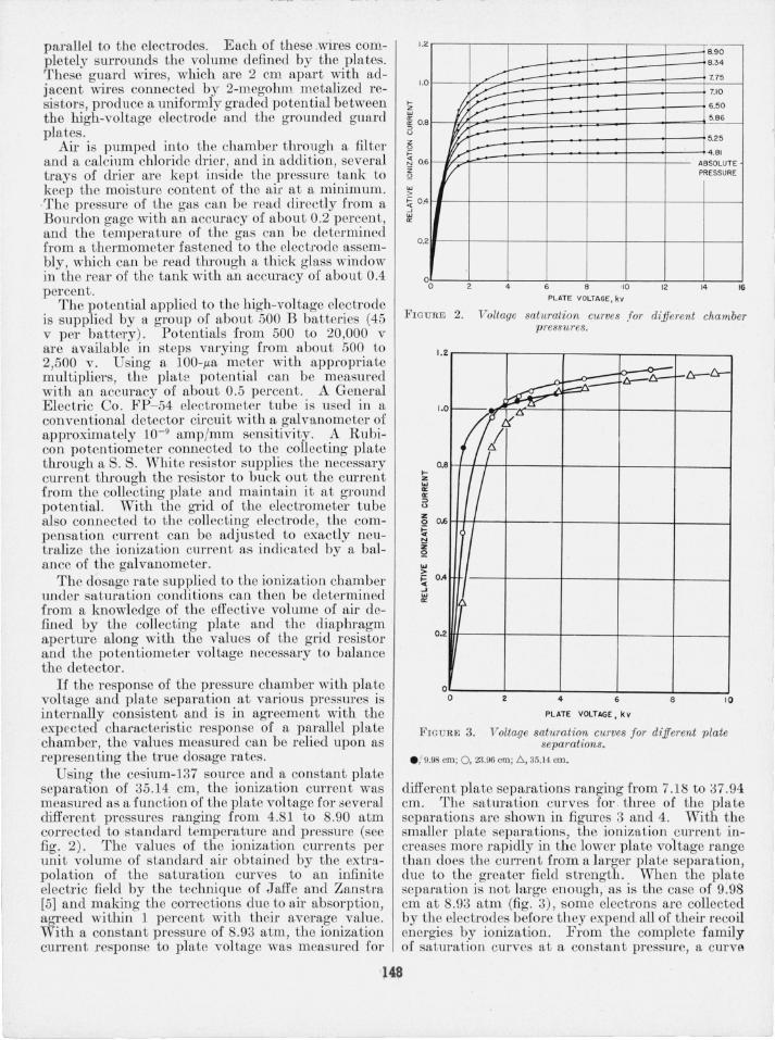
Using the cesium-137 source and a constant plate separation of 35.14 cm , the ionization current was measured as a function of the plate voltage for several different pressures ranging from 4.81 to 8.90 atm corrected to standard temperature and pressure (see fig. 2) . The values of the ionization currents per unit volume of standard air obtained by the extrapolation of the saturation curves to an infinite electric field by the technique of Jaffe and Zanstra [5] and making the corrections due to ail' absorption, agreed within 1 per cent with their average value. With a constant pressure of 8.93 atm, the ionization current response to plate voltage was measured for
1.2
1.0
0.8
0.6
0.4
0.2
o o
~ --:== a~ --Y;-: .=
); ...-------r
2 4 6
PLATE VOLTAGE, kv
8.90
8.34
7.75
7.10
6.50
5.86
5.25
A.81
ABSOLUTE PRESSURE
12 14 16
FIGURE 2. Voltage saturation curves ,for different chamber pressures.
.... z '" It: It: :::> <> Z 0
!;i N 2: 52
'" > ;: .. ~ .., It:
1. 2
J\.-
~ t::r-fr-
~
711 ~~ t
1.0
O.B
0.6
0 .4
0 .2
o o
1/
~ 2 4 8
PL ATE VOLTAGE. k v
r-l::r-l:r-
10
FIGU R E 3. Voltage saturation curves for different plate separations.
e, 9.98 em; 0 , 23.96 em; c", 35.14 em.
different plate separations ranging from 7.18 to 37.94 cm. The saturation curves for tlu'ee of the plate separations are shown ill figures 3 and 4. With the smaller plate separations, the ionization current increases more rapidly in the lower plate voltage range than does the current from a larger plate separation, due to the greater field strength. When the plate separation is not large enough, as is the case of 9.98 cm at 8.93 atm (fig . 3), some electrons are collected by the electrodes before they expend all of their recoil energies by ionization. From the complete family of saturation curves at a constant pressure, a curve
148

1.2
I 616~ r-l>--<' f-b-~~ 0 ;;A-~ I
~I--•
/ 6 J .4 !
t 211
0.
0 40 80 120 160 200 40 280 320. 360 4 00
fi ELD STRENGTH , v/cm
FIG U RE 4 . Field saluration curves for different plate separations. • , 9.98 em ; 0 , 23.96 em; .6., 35. 14 em.
of the ionization cLUTent versus the plate separation with con tant electric field was determined. The ionization curren t was found to fall off for plate separations less than about 150 em of equivalent tandard air. When corrected for the diameter of the gamma-ray beam and the ch~mber pressure, a minimum sufficient plate separatlOn of abou t 120 cm for O.661-Mev radiation was found. . .
A similar procedure wa followed m measurmg the radiation intensity from the cobalt-60 source. For the e quantum energies a minimum . plate separation of about 400 cm of st!1ndard mr 'yas found necessary to obtain the maxlIll.mn collectlI~g rate of the ions with a constant electnc field. ThIs
1.4,----,-----,-----,----,----,---,
0.21---- ----:A-:..-L---t---+---- -+---t-----j
FIGURE
4 8 12 16 20 24
k/F 2
5. Inverse-square plot fo r the source-diaphragm distance (F).
corresponds to a plate separation of about 335 ern of equivalent standard air when corrected for the beam diameter.
The dosage rates at the limiting diaphragm surface for the particular cesium and cobalt somces measmed in the manner just described were 6.91 ± 0.07 and 5.10 ± 0.05 r /hr, respectively. These values need to be corrected only for the air and aluminum absorp tion and for the diaphragm leakage.
A test of the inverse-square response was made with the pressure chamber for the two sources. The distance, F, between the center of the source and the limiting diaphragm surface was varied, and the concomitant ionization current was measured. These da ta are shown in figure 5, from which it is seen that F is very nearly equal to the effective source-diaphragm distance.
2 .2 . Extrapolation Chamber
A parallel-plate extrapola tion chamber [6] also was used to measure the dosage rat.es of the two sources. This chamber consists of two Lucite disks , the inner surfaces of which are painted with a conducting aquadag dispersion. Around each disk there is a concentric guard ring (fig . 6) . The Lucite disks are supported in, but insulated from, brass rings, one of which is threaded into the other so that the plate eparation can be varied. A complete revo-
T O DETECTOR
T
F IGURE 6.
1. o 2 I 2
II I tI " I I I SCAL E - I NCHES
S ection al view of extrapolation chamber showing approxt mate size of gamma-ray beam .
149

o :t. :t. >--
2.6
2.4
2.0
z I. w
6
a: a: ::> <>
5 I.
t: N Z Q
2
O. 8
O. 4
0 o
/ ,/
/ . /.
, , , , ,
/ /
V /
/
6 9 12 15
PLATE SEPARATION, mm
FIGURE 7. Extrapolation chamber curve for the cesium-137 source.
lution of one of the plates changes the plate separation by 0.150 cm, which is about 8 percent of the maximum plate separation.
By the use of this chamber with a shielded condenser-potentiometer circuit and a vibrating-reed electrometer as an indicator, the ionization current. was measured as a function of the plate separation. A curve for the cesium source is shown in figure 7. From the slope of the straight line determined by the most points, the average ionization current per centimeter can be found. This quantity, together with the values of the temperature, pressure, and the area of the diaphragm aperture, determines a dosage rate at the limiting diaphragm surface. For the cesium and cobalt sources, dosage rates of 6.72 ± 0.13 and 5.20±0.10 r /hr, respectively, were calculated. These values need to be corrected only for air and Lucite absorption and for the diaphragm leakage.
2.3. Thimble Chamber
A 25-r Victoreen thimble chamber was also used to measure the dosage rates of the two isotopes. This chamber and charger unit had been previously calibrated for radium radiation, and a scale correction was determined with an accuracy of about 2 percent. With this chamber the dosage rates were measured for the two sources at a sufficient distance from the diaphragm, such that the largest dimension of the sensitive volume of the chamber was less than one-half the diameter of the umbra portion of the radiation. With the same geometry, readings were taken with different thicknesses of Lucite shells around the sensitive volume. The rate of ionization in the chamber at first increased with shell thickness due to the approach to electronic equilibrium, and then decreased with additional
shell thickness due to absorption in the Lucite. By extrapolating the slope of the line due to absorption to zero shell thickness, a dosage rate was determined . This value is taken to be a good approximation to the ionization rate with electronic equilibrium and no Lucite absorption. The shell thicknesses necessary for electronic equilibrium were estimated to be about 1.0 mm for 0.661-Mev radiation and 1.3 mm for 1.3-Mev radiation. The extrapolated values were about 8.8 percent for cesium and 4.5 percent for cobalt higher than the respective values with electronic equilibrium shell thicknesses. Extrapolated values of 7.04 ±0.21 and 5.20±0.15 r/hr were calculated for the cesium and cobalt sources, respectively. These values are corrected for temperature and pressure and are for the same source-limiting aperture distance used with the other two chambers. These values can then be compared directly with the pressure-chamber results.
3 . Corrections and Results
The sensitive volume of the pressure ionization chamber is determined by the length of the collector plates and the area of the limiting aperture. However, there is an error involved in considering only the radiation that passes through this aperture, as the thickness of the diaphragm is not small compared to its distance from the source of radiation, and thus some of the radiation will pass through the edge of the diaphragm and enter the chamber. To estimate the magnitude of this error it was necessary to determine what fraction of the total radiation producing ionization in the chamber was transmitted through the edge of the diaphragm. This was done by considering the activity of the source to be distributed unifoI'mly over the surface of a thin disk located at the center of the source (fig. 8). If p and () are the polar coordinates of a point on the surface of the disk and r is the distance from the source-diaphragm-chamber axis in a fixed direction at a distance D along the axis from the source, where D is equal to or greater than the distance d between the source and the outer diaphragm surface, then the total amount of radiation received by the ionization chamber is given by
i Tm"i pmax {2". 27T e-!,O(T. p. 8) prdr pdO, o 0 , 0
where li is the thickness of lead traversed by gamma rays emitted at p, 0, which pass through the point r, and JL is the linear absorption coefficient of lead for the radiation in question . The max.-imum value of p is equal to the radius of the source, and the maximum value of r is taken to be that radius at which the radiation intensity is negligible for all values of p and 0. The absorber thickness li is given by
o=d-.p { p(r cos 0- p)+v p2(p -r cos 0)2+(a2- p2) (r2+ p2- 2rp cos oj}
r2+p2-2rp cos 0
,ISO

~ LEAD DIAPHRAGM
APERTURE OF RADIUS a ~ ~
r~[~~~~~~~=-~ --~~~~~~8~~------~~=:~~~)
I. f+------I ' D _ d ~: I FIGURE 8. S.chef!1atic indi~alion of the variables l'eq1tired for
determmalton of the dtaphragm leakage correction.
for al~ positive values of the right-hand term. When the nght-J:.an~ ter~n becomes negative, 0 is equal to zer~. ThIs. trIple mtegral was evalua ted by numericalmteg!'atIOn, a.nd th~ resulting intensity was compared wIth the mtenslty that was ~assed through the unobstructed aperture for the ceSHlln and cobalt sources. In the case of cesium the correction was 2.40 percent, for cobalt it wa 4.85 percen t. These valut's are believed to be accurate to abou t 10 pOl·cent.
The resistance of Lhe S. . White resistor used in the grid circuit of the electrometer was measured during the course of the experiment and found to have a value of 3.003 X 10⁹ ohms at 26° C and 3.161 X 10.9 ohms a.t 23° C. The precise temperature of the resIstor dUl'lng a set of measurements was not known but was take? .to be the average value of the temperature of the all' m the tank and room temperature. The maximum error due to this resistor is estimated to b e about 1 percent.
By the application of the corrections due to air aluminum, and Lucite absorptions [7], and that du~ to the diap~agm leakage, th e correct dosage rates measured Wlth the pressure and the extrapolation chambers were calculated. These values are tabulated in table 1, along with the thimble-chamber values. The cobalt ource had been calibrated on June 1, 1~49. The calibrated value corrected to the approx~ate date of this experiment was 5.05 ±0.15 r /hr at a dIstance equal to the source-diaphragm distance. The errors assigned to the various value have been e~timated and consist largely of the errors already dIscussed.
TABLE 1. Com parative values of the dosage rates at the limiting diaphragm swjace
Cesium·137 Cobalt-6Q - ---- -----_·_-_· __ ·_-·----1-----1
Pressure chambcL ____ . _______ . ______ __ _ "E xtrapolation cha m bcr _______ __ . _____ _ _ Thimble chamber. ................... .
r/hr 7. 17± 0. 14 7.03± 0.2 l 7.0·j± 0.2l
r/hr .). 1.)± 0. ] 0 .). 17± 0. 1.' 5.20±0.15
psing the pressure chamber, the absorption coeffiClCllts for the gamma rays of cesium and cobalt were measured for lead, copper, and tin. Sets of standard absorbers ranging in thickness from 0.050 to about 3 cm were used in this determination. The valu~s of t?-e measured linear absorption coefficients are listed m table 2, along with the best available theoretical values []. The theoretical values are believed to be accurate within a few percent. The
151
lower encrgy values are the most inaccurate because of the e~Tor in de~ermil1ing the more prominent photoclectnc absorptIOll coefficient.
T AB LE 2. Lineal' absorption coefficients
____ C __ es_iu_n_'.l~3 --I ----I-----cobaH.60----L ead Tin Co pper Lead Till Copper
cm-1 cm- i em-I cm-t cm-i cm-1 :Measured . . . . ........ l.2] 0 0.535 0.635 0.664 0.372 0.46.5 Calculated. . .......... 1. 202 .542 . 644 .674 .371 .466
4. Conclusion The response of the pressure ionization chamber
for radiation energies below 1.3 Mev indicates that absolute dosage rates can be determined within a few percen t in accordance with the international definition of the roentgen. The accuracy of the values obtained with this pressure chamber are limited mainly by three factors : (1) the ' 1'1'01' in the measurement of the ionization cun-ent, (2) the determination of the saturation curren t obtained by a JafJ'eZanstr~ ex~rapolation , and (3) the accuracy of the d~termll1atlOn of the area of the diaphragm aperture, wIth the con ection factor due to leakage of radiation through the edge of the diaphragm . A consideration of these fa<itors , together with the inherent tolerances of the chamber , led to an estimated error of 2 percent for the over-all accuracy of the results. .r t appears that it is possible to get an accmacy that will allow dosage-rate measurements to be made with somewhat less than 1 percent error by minimizing the uncertainties arising from the sour ces listed above.
The dosage rates measured with the extrapolation and thimble chambers are in good agreement with the values determined with the pressure chamber. This is especially gratifying in the case of the thimble chamber, as it is used extensively and there has been some question regarding energy dependence for radiation in ~he million-:-clectron-vol t region . The Victoreen tlumble chamber was not designed to m.easure the dose. resul~ing from high energy radiation ; however, I t was found that the dose due to collimated cesium~137 and. cobalt-50 gamma-rays co uld be cletermll1ed relatIvely accurately by placing Lucite shells a round the thimble to provide electronic equilibrium for the radiation i ll question.
S. References [1] L. S. Taylor, G. Singer, and A. L. Charlton, Am. J .
Roentgenol. Radium Therapy XLIV, No.3 (1940). [2] L. S. Taylor and G. Singer, Am. J. Roentgenol. Radium
Therapy X LI, No.2 (1939). [3] L. M. Langer and R. D. Moffat, Phvs. R ev. 78, 7(
(1950). • [4] D . A. Lind, J . R. Brown, and J . W. M. D uMo nd, Phys.
Rev. 76, 1838 (1949). [5] H. Zanstra, Physica 2, 817 (1935). [6] G. Failla, Radiology XXIX, 262 (1937). [7] J. A. Victoreen, J. Applied P hys. 20, 1141 (1949). [8] Gladys White, Tables of X-ray attenuation coefficients
with introductory notes, NBS Repor t 1003 (May 7, 1951).
IVASHINGTON, October 12, 1951.