Measurement Equipment Development of Stability Evaluation ...
16
TUNNEL & UNDERGROUND SPACE Vol.28, No.3, 2018, pp.193-208 https://doi.org/10.7474/TUS.2018.28.3.193 ISSN: 1225-1275(Print) ISSN: 2287-1748(Online) TECHNICAL NOTES 무인항공기를 이용한 절리사면의 안정성평가 계측장비 개발 이현철 * , 권기문, 문창은, 조영훈 주식회사 구주엔지니어링 Measurement Equipment Development of Stability Evaluation for Joint Slope using Unmaned Aerial Vehicle Hyun Chol Lee * , Ki Mun Kwon, Chang Eun Moon, and Yeong Hun Jo Guju Engineering Inc. *Corresponding author: [email protected] ABSTRACT Received: April 25, 2018 Revised: May 15, 2018 Accepted: May 15, 2018 In order to interpret rock slope safely and effectively, the mechanical properties of the rock must be carefully investigated. However, due to the limitations of clinometer usage, a new measure of measurement is required to complement these limitations. In this study, a measuring device was developed to analyze the characteristics of joint orientation, and to apply the orientation of joint to the field. The developed measuring equipment is divided into analysis software and hardware. The hardware was composed of a measuring module that measures the joint orientation of rock and a transport module that transmits the measurement data. The software was developed to analyze the orientation of the joint from the data obtained from the measuring module and is named Drone Joint Orientation Survey Measurement. The developed measuring equipment was well field capable if it could not be measured by the inspector, such as in areas where access was difficult, and was capable of effectively analyzing the lab test results for the orientation of the joint. Keywords: Unmaned Aerial Vehicle, Joint measurement system, Joint orientation, Xbee 초록 암반사면을 안전하고 효과적으로 해석하기 위해서 암반의 역학적 특성을 면밀하게 조사해야 한다. 하지 만 클리노미터를 사용한 절리조사의 한계점으로 인해 이를 보완한 새로운 측정법의 연구가 필요하다. 본 연구에서는 절리방향의 특성을 분석하기 위해 절리의 방향성을 현장에 적용할 수 있는 절리조사 측정장 비를 개발하였다. 개발된 측정장비는 해석 소프트웨어와 하드웨어로 구분된다. 하드웨어는 암반 절리 방 향성을 측정하는 측정모듈, 측정자료를 전송하는 전송모듈로 구성되었다. 소프트웨어는 측정모듈을 통 해 얻은 데이터로부터 절리의 방향성을 분석하기 위해 개발하였으며 Drone Joint Orientation Survey Measurement로 명명하였다. 개발된 측정장비는 접근이 어려운 지역 등 조사자가 측정할 수 없는 경우 에 현장적용성이 양호하며 절리의 방향성에 대한 실내시험결과를 효과적으로 분석할 수 있었다. 핵심어: 무인항공기, 절리측정시스템, 절리방향성, 지그비 Ⓒ The Korean Society for Rock Mechanics and Rock Engineering 2018. This is an Open Access article distributed under the terms of the Creative Commons Attrib- ution Non-Commercial License (http://creativecommons.org/ licenses/by-nc/4.0/) which permits unrestricted non-commercial use, distribution, and reproduction in any medium, provided the original work is properly cited.
Transcript of Measurement Equipment Development of Stability Evaluation ...
TUNNEL & UNDERGROUND SPACE Vol.28, No.3, 2018, pp.193-208
https://doi.org/10.7474/TUS.2018.28.3.193 ISSN: 1225-1275(Print) ISSN: 2287-1748(Online)
TECHNICAL NOTES
무인항공기를 이용한 절리사면의 안정성평가 계측장비 개발
이현철*, 권기문, 문창은, 조영훈
주식회사 구주엔지니어링
Measurement Equipment Development of Stability Evaluation for
Joint Slope using Unmaned Aerial Vehicle
Hyun Chol Lee*, Ki Mun Kwon, Chang Eun Moon, and Yeong Hun Jo
Guju Engineering Inc.
*Corresponding author: [email protected]
ABSTRACT
Received: April 25, 2018
Revised: May 15, 2018
Accepted: May 15, 2018
In order to interpret rock slope safely and effectively, the mechanical properties of the rock
must be carefully investigated. However, due to the limitations of clinometer usage, a new
measure of measurement is required to complement these limitations. In this study, a
measuring device was developed to analyze the characteristics of joint orientation, and to
apply the orientation of joint to the field. The developed measuring equipment is divided into
analysis software and hardware. The hardware was composed of a measuring module that
measures the joint orientation of rock and a transport module that transmits the measurement
data. The software was developed to analyze the orientation of the joint from the data
obtained from the measuring module and is named Drone Joint Orientation Survey Measurement.
The developed measuring equipment was well field capable if it could not be measured by the
inspector, such as in areas where access was difficult, and was capable of effectively analyzing
the lab test results for the orientation of the joint.
Keywords: Unmaned Aerial Vehicle, Joint measurement system, Joint orientation, Xbee
초록
암반사면을 안전하고 효과적으로 해석하기 위해서 암반의 역학적 특성을 면밀하게 조사해야 한다. 하지
만 클리노미터를 사용한 절리조사의 한계점으로 인해 이를 보완한 새로운 측정법의 연구가 필요하다. 본
연구에서는 절리방향의 특성을 분석하기 위해 절리의 방향성을 현장에 적용할 수 있는 절리조사 측정장
비를 개발하였다. 개발된 측정장비는 해석 소프트웨어와 하드웨어로 구분된다. 하드웨어는 암반 절리 방
향성을 측정하는 측정모듈, 측정자료를 전송하는 전송모듈로 구성되었다. 소프트웨어는 측정모듈을 통
해 얻은 데이터로부터 절리의 방향성을 분석하기 위해 개발하였으며 Drone Joint Orientation Survey
Measurement로 명명하였다. 개발된 측정장비는 접근이 어려운 지역 등 조사자가 측정할 수 없는 경우
에 현장적용성이 양호하며 절리의 방향성에 대한 실내시험결과를 효과적으로 분석할 수 있었다.
핵심어: 무인항공기, 절리측정시스템, 절리방향성, 지그비
Ⓒ The Korean Society for Rock Mechanics and Rock Engineering 2018. This is an Open Access article distributed under the terms of the Creative Commons Attrib-ution Non-Commercial License (http://creativecommons.org/ licenses/by-nc/4.0/) which permits unrestricted non-commercial use, distribution, and reproduction in any medium, provided the original work is properly cited.
194 ∙ Hyun Chol Lee, Ki Mun Kwon, Chang Eun Moon, and Yeong Hun Jo
TUNNEL & UNDERGROUND SPACE Vol. 28, No. 3, 2018
1. Introduction
In general, rock analysis exposed to the surface is classified as a stable analysis considering the joint orientation and the
mechanical characteristics. This is because the stability of the rock is associated with the orientation of the joint and its
mechanical properties.
The characteristics of the rock joint structure are derived from the analysis of the joint surface and the statistical analysis
after making contact with the joint surface, such as the survey of the scanline, the investigation of the window, and the
investigation by the clinometer (Son et al., 2014).
Currently, the use of long-distance survey techniques using photogrammetry techniques and laser scanner methods is
increasing, but this is due to the lack of efficiency in analysis of joint structures in large rock and the subjective opinions of the
inspector (Moffitt and Mikhail, 1980).
To solve these problems, this study attempted to develop a device for measuring the field joint orientation for the analysis
of joint slope. The shrink-level measurement device is divided into hardware and analytic software. The hardware was
configured with drones, arduino uno, servo motor, joint orientation measuring module, and wireless transmission module of
measurement data to measure the direction of joint structures. The software has been developed to analyze the orientation of
joint by printing the data obtained from the measuring module on-screen, and it is called Drone Joint Survey.
The purpose of this study is to develop a device to measure the joint orientation, a mechanical feature of the rock, and to
measure the joint orientation module, in order to safely and effectively interpret the rock slope through compare with the
existing clinometer.
2. Theoretical Background
For the purpose of evaluating the mechanical stability, the measurements are made on the discontinuous surfaces, such as
the joint, and the consequences are likely to be the potential failure aspects of the slope based on the properties of these
discontinuous surfaces (Lee, 2016).
The dip angle and dip direction, especially on the discontinuous surface, are the major factors that determine the type of
failure upon the collapse of the slope.
A compass clinometer is used to measure the joint surface. (compass clinometer, geological compass, clino-compass,
inclinometer with compass etc.). Since the direction of the slope on the clinometer must be measured in a horizontal plane, it
is necessary to adjust the equipment horizontally while the joint surface is closely attached to it. Measure the angle after the
instructions for compass are stabilized.

Measurement Equipment Development of Stability Evaluation for Joint Slope using Unmaned Aerial Vehicle ∙ 195
TUNNEL & UNDERGROUND SPACE Vol. 28, No. 3, 2018
rock slope
Fig. 1. Measurement diagram using drone
Fig. 2. Calculation diagram of degree
Fig. 1 shows a schematic diagram of the joint orientation measurement of rock slope using drones. At point C, hovering
drones to measure the value of the horizontal distance a to the rock slope through the ultrasonic sensors and rotate the
measured angle, 30° A, in a clockwise direction from the horizontal plane using the servo motor.
Determine the distance value of c that connects the two points on the slope (A, B) and the second point (A) by forming a
triangle with each other and using the following expression.
Determine the value of the angle of inclination ( ) by using the triangle’s second cosine law in Fig. 2.
cos
cos
(1)
The slope direction of the slope of rock slope joint is calculated from the angle of euler. The rotation order is ZYX
(Roll-Pitch-Yaw). Calculate the rotation results of the target coordinate system against the reference coordinate system as

196 ∙ Hyun Chol Lee, Ki Mun Kwon, Chang Eun Moon, and Yeong Hun Jo
TUNNEL & UNDERGROUND SPACE Vol. 28, No. 3, 2018
follows.
First, rotate the reference coordinate system about the X-axis (Yaw rate) :
Second, rotate the reference coordinate system about the Y axis (pitch) :
Third, rotate the reference coordinate system about the Z axis (Roll). :
∅
cos cos sin∅ sin cos cos∅ sin cos∅ sin cos sin∅ sin
cos sin sin∅ sin sin cos∅ cos cos∅ sin sin sin∅ cos sin sin∅ cos cos∅ cos
(2)
cos∅ sin∅ sin∅ cos∅
(3)
cos sin
sin cos
(4)
cos sin
sin cos
(5)
It is possible to calculate the euler angle from the rotation matrix R as follows. The elements in row i and column j of matrix
R are used in the following expression.
(6)
When θ is ( ) :
(7)
When θ is ( ) :

Measurement Equipment Development of Stability Evaluation for Joint Slope using Unmaned Aerial Vehicle ∙ 197
TUNNEL & UNDERGROUND SPACE Vol. 28, No. 3, 2018
(8)
When the pitch angle is near , the cos≈ . Calculate it as follows.
sin sin
sin cos
sin sin
sin cos
(9)
(10)
3. Joint Survey System
3.1 Composition and Principle of system
In this study, data acquisition and analysis was performed using sketch developed by SmartProjects company. The system
consists of Arduino Uno, Sensor modules, Xbee modules, and Blynk. Fig. 3 shows the schematic diagram of the joint survey
system.
3.2 Arduino Uno
Arduino Uno uses Atmel's 16 MHz microcontroller ATmega 328 capable of connecting multiple peripheral devices across
a total of 20 I/O pins, providing connectivity and Table 1 presents technical specifications for the Arduino Uno (Simon,
2011).
3.3 9 Axes Motion Sensor
It is based on Bosch's BNO055 absolute orientation sensor, it runs a 3-axes 14-bit accelerometer, 3-axes 16-bit gyroscope,
3-axes earth magnetism, and BSX 3.0 FusionLib Software. In this study, measurements from a 9-axis motion sensor are used
to determine the dip direction of the rock slope. Table 2 shows the technical specifications for the 9 Axes Motion Shield.

198 ∙ Hyun Chol Lee, Ki Mun Kwon, Chang Eun Moon, and Yeong Hun Jo
TUNNEL & UNDERGROUND SPACE Vol. 28, No. 3, 2018
Arduino Uno
PC Monitor
ATmega328 Microcontroller
USB
Digital, Analog Pins
Sensor Modules
Measured
Value
9 Axes Motion Sensor Module
Ultrasonic Sensor Module
Altitude Sensor Module
(a) Arduino Uno (b) Sensor Modules
Xbee Module
PC Monitor
Measured Values from Sensors
Wireless Transmission
XCTU Configure
Blynk
Blynk Server
Blynk App
Blynk Libraries
Internet Access of your choice
Ethernet, Wi-Fi, 3G
ESP-8266
(c) Xbee Module (d) Blynk
(e) Photograph
Fig. 3. Conceptual diagram of the joint survey System
Table 1. Technical Specification (Arduino Uno)
Division Specifications
Microcontroller ATmega328P
Operating Voltage 5 V
Digital I/O Pins 14(of which 6 provide PWM output)
DC Current per I/O Pin 20 mA
Flash Memory 32KB(ATmega328P) of which 0.5KB used by bootloader
Clock Speed 16 MHz
Table 2. Technical Specification (9 Axes Motion Shield)
Division Specifications
Chip based BOSCH Sensortech BNO055
Thinker Kit interface 2x TWI, 2x OUT, 2x IN
Motion Sensors Triaxial accelerometer, Triaxial gyroscope, Triaxial geomagnetic
Fusion Engine 32-bit microcontroller with BSX3.0 FusionLib
Operating Voltage 5 / 3.3 V
Measurement Equipment Development of Stability Evaluation for Joint Slope using Unmaned Aerial Vehicle ∙ 199
TUNNEL & UNDERGROUND SPACE Vol. 28, No. 3, 2018
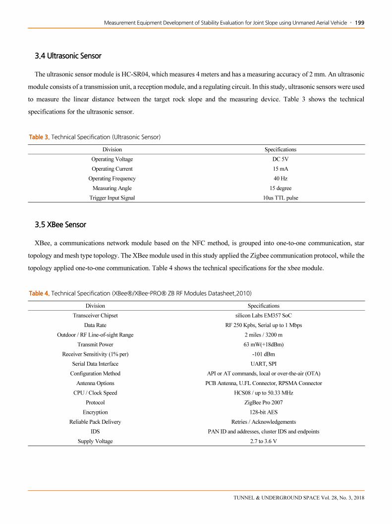
3.4 Ultrasonic Sensor
The ultrasonic sensor module is HC-SR04, which measures 4 meters and has a measuring accuracy of 2 mm. An ultrasonic
module consists of a transmission unit, a reception module, and a regulating circuit. In this study, ultrasonic sensors were used
to measure the linear distance between the target rock slope and the measuring device. Table 3 shows the technical
specifications for the ultrasonic sensor.
Table 3. Technical Specification (Ultrasonic Sensor)
Division Specifications
Operating Voltage DC 5V
Operating Current 15 mA
Operating Frequency 40 Hz
Measuring Angle 15 degree
Trigger Input Signal 10us TTL pulse
3.5 XBee Sensor
XBee, a communications network module based on the NFC method, is grouped into one-to-one communication, star
topology and mesh type topology. The XBee module used in this study applied the Zigbee communication protocol, while the
topology applied one-to-one communication. Table 4 shows the technical specifications for the xbee module.
Table 4. Technical Specification (XBee®/XBee-PRO® ZB RF Modules Datasheet,2010)
Division Specifications
Transceiver Chipset silicon Labs EM357 SoC
Data Rate RF 250 Kpbs, Serial up to 1 Mbps
Outdoor / RF Line-of-sight Range 2 miles / 3200 m
Transmit Power 63 mW(+18dBm)
Receiver Sensitivity (1% per) -101 dBm
Serial Data Interface UART, SPI
Configuration Method API or AT commands, local or over-the-air (OTA)
Antenna Options PCB Antenna, U.FL Connector, RPSMA Connector
CPU / Clock Speed HCS08 / up to 50.33 MHz
Protocol ZigBee Pro 2007
Encryption 128-bit AES
Reliable Pack Delivery Retries / Acknowledgements
IDS PAN ID and addresses, cluster IDS and endpoints
Supply Voltage 2.7 to 3.6 V

200 ∙ Hyun Chol Lee, Ki Mun Kwon, Chang Eun Moon, and Yeong Hun Jo
TUNNEL & UNDERGROUND SPACE Vol. 28, No. 3, 2018
3.6 Software of data acquired
Arduino’s integrated development environment is a cross-platform application software developed based on Java and C,
which is capable of compiling and uploading, and using C ++ language base for arduino operation (Hagan, 1980).
In this study, using sketches, data from both the Arduino Uno and the sensors were printed on the mobile computer.
3.7 Servo Motor
With TowerPro’s SG-90 product, SG-90 is a small, lightweight product with a high output power. The servo can rotate
about 180 degrees and is operated by three wires. It is used in this study to adjust the angle of the Drone Measure system.
Table 5 lists technical specifications for SG-90.
Table 5. Technical Specification (SG-90)
Division Specifications
Weight 9 g
Dimension 22.2 × 11.8 × 31 mm approx
Stall torque 1.8 kgf ・ cm
Operating speed 0.1s / 60 degree
Operating Voltage 4.8 V (~5V)
Dead band width 10 μs
Temperature range 0°C - 55°C
3.8 Unmaned Aerial Vehicle
It is a DJI's MAVIC PRO product, which uses forward and downstream vision sensors to accurately hovering rooms and
satellites where they are not captured, and also maintains a fixed altitude on the uneven terrain. Table 6 shows the technical
specifications for the MAVIC PRO.
Table 6. Technical Specification (MAVIC PRO)
Division Specifications
Flight time 27 mins
Control range 7 km
Speed 65 km/h
Gimbal 3-axis
Video resolution 4K
Camera resolution 12 MP

Measurement Equipment Development of Stability Evaluation for Joint Slope using Unmaned Aerial Vehicle ∙ 201
TUNNEL & UNDERGROUND SPACE Vol. 28, No. 3, 2018
3.9 ESP 8266
ESP 8266 is a micro-controller designed by Espressif Systems, and since a large number of ESP-xx modules operate only
at 3.3 V, a 3.3 V power supply is required.
The GPIO (General Purpose Input Output) is a pin that can be controlled by the ESP 8266 module, like the pin in the
Arduino, with a different number of pins available for each ESP-xx module. Table 7 lists technical specifications for ESP
8266.
Table 7. Technical Specification (ESP8266)
Division Specifications
Voltage 3.3 V
Current consumption 10 uA – 170 mA
Flash memory attachable 16MB max (512K normal)
Processor Tensilica L106 32 bit
Processor speed 80-160 MHz
RAM 32 K + 80 K
GPIOs 17 (multiplexed with other functions)
ADC (Analog to Digital) 1 input with 1024 step resolution
802.11 support b/g/n/d/e/i/k/r
Maximum concurrent TCP connections 5
3.10 Blynk
Blynk is a platform that enables iOS and Android applications to control the makers of IoT devices such as Arduino and
Raspberry Pies, and it is a platform that supports virtual, hardware-to-hardware connectivity.
4. Test Result
4.1 Result of Joint Data
For the purpose of making use of the joint survey system applied to this study, the dip angle was increased from 50° to 10°
for each pair of surfaces, and measured from 10° to 90° for the dip direction. In the case of a 50° dip angle, the dip direction
is measured from 90° to 140° and examined until the angle is 80°.
In the lab model test, the results of measurements using a clinometer were compared with the results obtained by a joint
survey system. Fig. 4 shows the hardware configuration diagrams of the joint survey system. Fig. 5 represents a conventional
survey device.
In this study, the data from lab tests were used to calculate the orientation of the joint and compared to the actual joint data

202 ∙ Hyun Chol Lee, Ki Mun Kwon, Chang Eun Moon, and Yeong Hun Jo
TUNNEL & UNDERGROUND SPACE Vol. 28, No. 3, 2018
obtained using the clinometer and mobile application.
+X
-Z
+Y
-X
+Z
-Y
①②
③
④
⑤
⑥ ⑦
⑧ ① Arduino Uno
② Power Supply
③ Arduino 9 axes motion shield
④ Arduino wireless SD shield
⑤ Arduino proto shield
⑥ ESP-8266
⑦ Ultrasonic sensor
⑧ SG-90
(a) Conceptual diagram
(b) Photography (c) Joint orientation test model (d) Test photography
Fig. 4. Joint orientation test apparatus
(a) Clinometer (b) Mobile application
Fig. 5. Clinometer and Mobile application
4.2 Reliability Analysis of Data
40 joints and 20 joints were selected to directly compare the joint orientation and to analyze reliability in the lab test and in
the field test. As a result of the measurement error in the dip angle and the measured error in the dip direction of the slope of
the clinometer are ± 5° and ± 10° respectively (Ewan and West, 1981), the machine error in the clinometer may be produced
in ± 1° to 2°. It has been analyzed that no data exceeds the tolerance range (dip : ± 7°, dip direction : ± 12°) set in this study
(Park et al., 2015).

Measurement Equipment Development of Stability Evaluation for Joint Slope using Unmaned Aerial Vehicle ∙ 203
TUNNEL & UNDERGROUND SPACE Vol. 28, No. 3, 2018
Table 8. Comparison of each joint orientation in the lab test (Clinometer and Drone Measure System and Mobile application)
(Unit : degree,°)
No.
Clinometer
(a)
Drone Measure System
(b)
Mobile application
(c)
Difference
(a:b)
Difference
(b:c)
DipDip
DirectionDip
Dip
DirectionDip
Dip
DirectionDip
Dip
DirectionDip
Dip
Direction
1 51 134.00 48.11 128.61 50 131.00 2.89 5.39 1.89 2.39
2 49 118.00 45.34 123.56 49 120.00 3.66 5.56 3.66 3.56
3 50 123.00 47.26 115.65 51 121.00 2.74 7.35 3.74 5.35
4 49 107.00 52.48 101.66 51 108.00 3.48 5.34 1.48 6.34
5 49 100.00 53.54 107.31 50 102.00 4.54 7.31 3.54 5.31
6 51 101.00 48.65 94.42 50 99.00 2.35 6.58 1.35 4.58
7 50 98.00 46.12 105.09 49 100.00 3.88 7.09 2.88 5.09
8 50 118.00 47.33 114.56 49 117.00 2.67 3.44 1.67 2.44
9 49 122.00 46.26 117.13 50 120.00 2.74 4.87 3.74 2.87
10 49 126.00 53.89 131.65 50 125.00 4.89 5.65 3.89 6.65
11 58 132.00 54.46 128.35 59 130.00 3.54 3.65 4.54 1.65
12 60 117.00 57.65 121.06 60 119.00 2.35 4.06 2.35 2.06
13 59 116.00 63.79 110.71 60 116.00 4.79 5.29 3.79 5.29
14 60 96.00 57.46 102.49 61 98.00 2.54 6.49 3.54 4.49
15 59 94.00 53.12 100.74 61 95.00 5.88 6.74 7.88 5.74
16 61 103.00 63.42 98.85 59 101.00 2.42 4.15 4.42 2.15
17 60 102.00 56.21 97.56 60 103.00 3.79 4.44 3.79 5.44
18 60 126.00 57.68 121.98 60 123.00 2.32 4.02 2.32 1.02
19 61 127.00 64.31 132.67 58 129.00 3.31 5.67 6.31 3.67
20 59 130.00 63.36 125.64 60 130.00 4.36 4.36 3.36 4.36
21 70 122.00 65.34 126.11 71 123.00 4.66 4.11 5.66 3.11
22 71 109.00 65.88 115.87 70 110.00 5.12 6.87 4.12 5.87
23 70 107.00 66.13 102.64 69 108.00 3.87 4.36 2.87 5.36
24 69 114.00 75.99 119.11 68 112.00 6.99 5.11 7.99 7.11
25 71 97.00 75.89 102.35 70 98.00 4.89 5.35 5.89 4.35
26 71 95.00 66.23 99.65 70 96.00 4.77 4.65 3.77 3.65
27 71 109.00 67.94 113.17 71 109.00 3.06 4.17 3.06 4.17
28 69 117.00 74.10 112.34 69 118.00 5.10 4.66 5.1 5.66
29 70 130.00 74.54 125.61 70 129.00 4.54 4.39 4.54 3.39
30 69 122.00 71.64 126.74 68 120.00 2.64 4.74 3.64 6.74
31 79 127.00 81.98 131.45 79 129.00 2.98 4.45 2.98 2.45
32 81 129.00 78.25 124.99 80 128.00 2.75 4.01 1.75 3.01
33 80 112.00 82.33 109.35 80 110.00 2.33 2.65 2.33 0.65
34 80 100.00 84.09 104.32 81 100.00 4.09 4.32 3.09 4.32
35 81 97.00 79.02 100.11 81 98.00 1.98 3.11 1.98 2.11
36 79 93.00 83.29 97.36 79 95.00 4.29 4.36 4.29 2.36
37 79 107.00 76.33 101.64 78 110.00 2.67 5.36 1.67 8.36
38 80 108.00 84.99 111.28 80 106.00 4.99 3.28 4.99 5.28
39 81 123.00 76.87 120.36 80 120.00 4.13 2.64 3.13 0.36
40 80 115.00 83.07 117.84 81 117.00 3.07 2.84 2.07 0.84
Average Error 3.70 4.82 3.63 3.99

204 ∙ Hyun Chol Lee, Ki Mun Kwon, Chang Eun Moon, and Yeong Hun Jo
TUNNEL & UNDERGROUND SPACE Vol. 28, No. 3, 2018
Table 8 compares the results of the 40-validated dip / dip direction measurements, with the mean error for the 40 dip / dip
directions being ± 3.63° / ± 3.99° as shown in Table 8. Table 9 compares the results of the 20-validated dip / dip direction
measurements, with the mean error for the 20 dip / dip directions being ± 6.81° / ± 5.24° as shown in Table 9. It has been
analyzed that no data exceeds the tolerance range set in this study.
4.3 Analysis of Error Cause
In comparing the direction of the joint using the clinometer and the Drone Measure System the cause of the maximum error
is determined by the difference in the measurement method of the joint surface.
It is assumed that, when using the Drone Measure System to obtain the joint orientation data, data errors are generated due
to the effects of the refraction of the ultrasonic sensors, the effects of magnetic fields of the magnetic sensor, the drone’s
propeller noise, wind speed and the effects of temperature.
Table 9. Comparison of each joint orientation in the field test (Clinometer and Drone Measure System and Mobile application)
(Unit : degree,°)
No.
Clinometer
(a)Drone Measure System (b)
Mobile application
(c)
Difference
(a:b)
Difference
(b:c)
DipDip
DirectionDip
Dip
DirectionDip
Dip
DirectionDip
Dip
DirectionDip
Dip
Direction
1 60 276.00 51.82 274.35 61 277.00 8.18 1.65 9.18 2.65
2 64 264.00 69.34 260.12 65 262.00 5.34 3.88 4.34 1.88
3 66 273.00 71.65 268.64 66 270.00 5.65 4.36 5.65 1.36
4 66 264.00 60.56 268.36 67 266.00 5.44 4.36 6.44 2.36
5 68 262.00 62.13 254.21 68 261.00 5.87 7.79 5.87 6.79
6 63 271.00 70.61 267.84 64 273.00 7.61 3.16 6.61 5.16
7 68 258.00 60.89 266.32 67 260.00 7.11 8.32 6.11 6.32
8 69 279.00 62.36 274.19 70 278.00 6.64 4.81 7.64 3.81
9 70 265.00 64.12 260.39 71 264.00 5.88 4.61 6.88 3.61
10 69 264.00 63.89 257.59 68 266.00 5.11 6.41 4.11 8.41
11 73 277.00 65.24 272.88 73 280.00 7.76 4.12 7.76 7.12
12 74 275.00 68.26 280.36 75 274.00 5.74 5.36 6.74 6.36
13 61 271.00 68.79 275.68 62 273.00 7.79 4.68 6.79 2.68
14 66 265.00 57.46 261.08 65 265.00 8.54 3.92 7.54 3.92
15 71 270.00 64.98 263.85 72 271.00 6.02 6.15 7.02 7.15
16 70 279.00 63.42 271.48 69 278.00 6.58 7.52 5.58 6.52
17 71 262.00 64.24 269.82 71 263.00 6.76 7.82 6.76 6.82
18 67 276.00 57.68 270.33 67 276.00 9.32 5.67 9.32 5.67
19 74 280.00 64.31 275.21 75 281.00 9.69 4.79 10.69 5.79
20 77 274.00 71.89 268.62 76 274.00 5.11 5.38 4.11 5.38
Average Error 6.81 5.24 6.76 4.99

Measurement Equipment Development of Stability Evaluation for Joint Slope using Unmaned Aerial Vehicle ∙ 205
TUNNEL & UNDERGROUND SPACE Vol. 28, No. 3, 2018
4.4 Analysis Result of the stereographic projection method
In the data analysis program, we measured the joint in the model slope and found that a total of 40 joints in the lab test and
20 joints in the field were measured, and depending on the orientation of the joint, a variety of joints were developed in the
model slope.
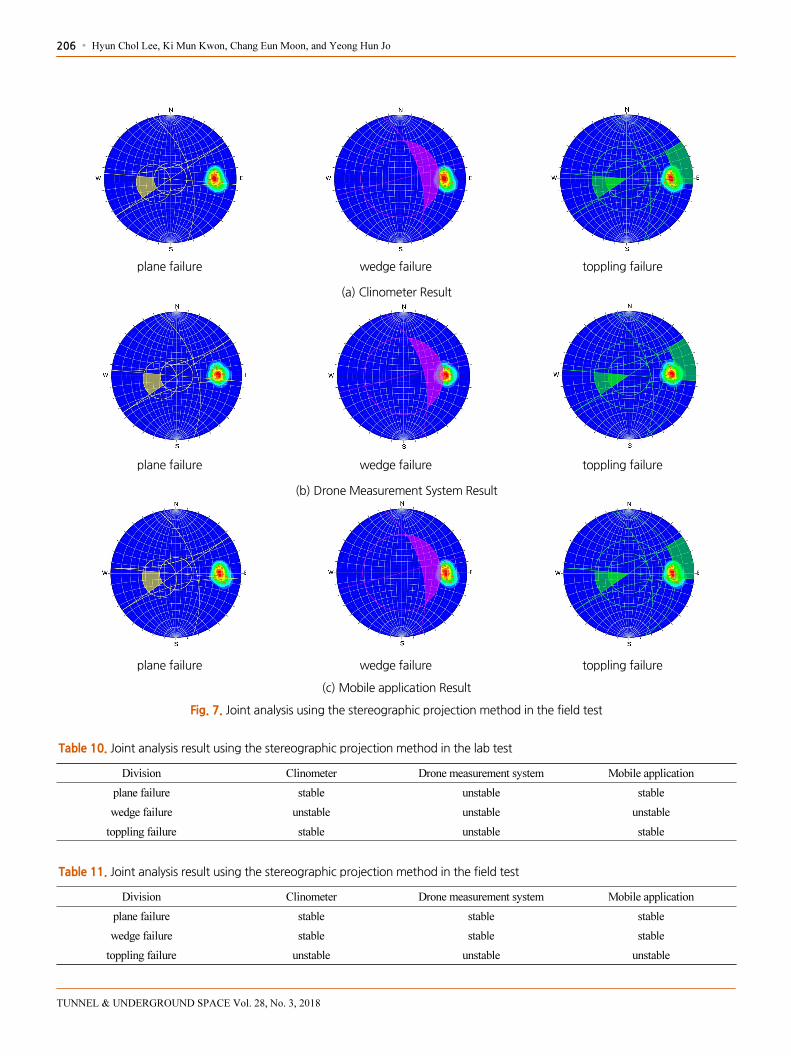
Fig. 6 and Fig. 7 indicates the destructive type of each measuring instrument according to the measurement results of joint
orientation in the lab test and in the field test. For each measuring instrument, the joint stability results are shown in Table 10
and Table 11.
plane failure wedge failure toppling failure
(a) Clinometer Result
plane failure wedge failure toppling failure
(b) Drone Measurement System Result
plane failure wedge failure toppling failure
(c) Mobile application Result
Fig. 6. Joint analysis using the stereographic projection method in the lab test
206 ∙ Hyun Chol Lee, Ki Mun Kwon, Chang Eun Moon, and Yeong Hun Jo
TUNNEL & UNDERGROUND SPACE Vol. 28, No. 3, 2018
plane failure wedge failure toppling failure
(a) Clinometer Result
plane failure wedge failure toppling failure
(b) Drone Measurement System Result
plane failure wedge failure toppling failure
(c) Mobile application Result
Fig. 7. Joint analysis using the stereographic projection method in the field test
Table 10. Joint analysis result using the stereographic projection method in the lab test
Division Clinometer Drone measurement system Mobile application
plane failure stable unstable stable
wedge failure unstable unstable unstable
toppling failure stable unstable stable
Table 11. Joint analysis result using the stereographic projection method in the field test
Division Clinometer Drone measurement system Mobile application
plane failure stable stable stable
wedge failure stable stable stable
toppling failure unstable unstable unstable

Measurement Equipment Development of Stability Evaluation for Joint Slope using Unmaned Aerial Vehicle ∙ 207
TUNNEL & UNDERGROUND SPACE Vol. 28, No. 3, 2018
5. Conclusions
In this study, the orientation of joint was measured automatically using the Drone Measure System, and the reliability of
joint orientation using Drone Measure System was compared with the previous joint survey method. The results of the above
study are as follows.
1. Since the test results are for the tolerance of joint orientation measured using a clinometer, the results of the comparison
and analysis show that the deviation in the joint orientation measured by the Drone Measure system is ± 3° in the lab test
± 6° in the field test. The results are considered reliable data since they are within the tolerance range of ± 7° and ± 12° in
the dip and dip direction set forth in this study.
2. When analyzing the causes of errors, it is analyzed that errors occurred due to differences in the measurement methods of
joint. When measuring the joint orientation using the Drone Measure System, the effects of refraction on the joint surface,
the effects of magnetic fields, and temperature are shown to cause errors in the lab test.
3. The joint measurement method using Drone Measure System secured the safety of the investigator and improved the
efficiency of the survey by resolving the constraints of the previous joint survey method, namely, restriction of
accessibility.
4. The results of the stereographic projection method show that the Drone Measure system shows conservative results
compared to the previous methods in the lab test.
5. As a result of a field test, the problem of error in ultrasonic sensors caused by the drone's propeller noise should be
suggested to use a low-noise propeller, consider the effects of wind speed during field measurement, and improve flight
time and battery charge of the drone.
ACKNOWLEDGMENTS
This work was supported by a Korea Agency for Infrastructure Technology Advancement. (2017 year, 1615008745)
REFERENCES
Ewan, V. J and West, G, 1981, Reproducibility of joint orientation measurements in rock, Transport and Road Research Laboratory
supplementary report 702, 18P, International Journal of Rock Mechanics and Mining Science & Geomechanics Abstracts,
Vol. 19, Issue 4, August 1982, Page 94.
Hagan, T. O., 1980, A case for Terrestrial photogrammetry in deep-mine rock structure studies, Int. J. Rock Mech. Min. Sci. 17, pp.
191-198.

208 ∙ Hyun Chol Lee, Ki Mun Kwon, Chang Eun Moon, and Yeong Hun Jo
TUNNEL & UNDERGROUND SPACE Vol. 28, No. 3, 2018
Lee, S. H., 2016, Development of mobile software for field survey of geological structures, Seoul National University, pp. 29-34.
Moffitt, F. H. and E. M. Mikhail, 1980, 3rd Eds, Photogrammetry, Happer & Row Publisher, 648p.
Park, S. H., Lee, S. G., Lee, B. K. and Kim, C. H, 2015, A Study on Reliability of Joint Orientation Measurements in Rock Slop
using 3D Laser Scanner, Tunnel and Underground Space, Vol. 25, No. 1, pp. 97-106.
Simon M., 2011, Programming Arduino Getting Started with Sketches, McGraw-Hill.
Son, Y. G., Kim, J. D., Jong, W. S., Kim, J. H. and Kim, K. S., 2014, Development of Joint Survey System using Photogrammetric,
Tunnel and Underground Space, Vol. 24, No. 1, pp. 55-66.
XBee®/XBee-PRO® ZB RF Modules Datasheet (PDF). Digi International Inc. pp. 10, 2010.