ME34-089-R01a
234
CNC SYSTEM OSP-P200MA MB-1000H, MA-100HII Series MF Unit MAINTENANCE MANUAL (1st Edition) Pub No. 5994-E (ME34-089-R1) Jan. 2012
description
Okuma MB500H
Transcript of ME34-089-R01a

CNC SYSTEM
OSP-P200MAMB-1000H, MA-100HII Series MF UnitMAINTENANCE MANUAL(1st Edition)Pub No. 5994-E (ME34-089-R1) Jan. 2012

5994-E P-(i)SAFETY PRECAUTIONS
SAFETY PRECAUTIONSThe machine is equipped with safety devices which serve to protect personnel and the machine itself fromhazards arising from unforeseen accidents. However, operators must not rely exclusively on these safetydevices: they must also become fully familiar with the safety guidelines presented below to ensure accident-free operation.This instruction manual and the warning signs attached to the machine cover only those hazards whichOkuma can predict. Be aware that they do not cover all possible hazards.
1. Precautions Relating to Installation(1) Please be noted about a primary power supply as follows.
• Do not draw the primary power supply from a distribution panel that also supplies a majornoise source (for example, an electric welder or electric discharge machine) since thiscould cause malfunction of the CNC unit.
• If possible, connect the machine to a ground not used by any other equipment. If there isno choice but to use a common ground, the other equipment must not generate a largeamount of noise (such as an electric welder or electric discharge machine).
(2) Installation EnvironmentObserve the following points when installing the control enclosure.
• Make sure that the CNC unit will not be subject to direct sunlight.
• Make sure that the control enclosure will not be splashed with chips, water, or oil.
• Make sure that the control enclosure and operation panel are not subject to excessivevibrations or shock.
• The permissible ambient temperature range for the control enclosure is 5 to 40°C (41 to104°F).
• The permissible ambient humidity range for the control enclosure is relative humidity 50%or less at 40°C (104°F) (no condensation).
• The maximum altitude at which the control enclosure can be used is 1000 m (3281ft.).
2. Points to Check before Turning on the Power(1) Close all the doors of the control enclosure and operation panel to prevent the entry of water,
chips, and dust.
(2) Make absolutely sure that there is nobody near the moving parts of the machine, and that thereare no obstacles around the machine, before starting machine operation.
(3) When turning on the power, turn on the main power disconnect switch first, then the CONTROLON switch on the operation panel.

5994-E P-(ii)SAFETY PRECAUTIONS
3. Precautions Relating to Operation(1) After turning on the power, carry out inspection and adjustment in accordance with the daily
inspection procedure described in this instruction manual.
(2) Use tools whose dimensions and type are appropriate for the work undertaken and the machinespecifications. Do not use badly worn tools since they can cause accidents.
(3) Do not, for any reason, touch the spindle or tool while spindle indexing is in progress since thespindle could rotate: this is dangerous.
(4) Check that the workpiece and tool are properly secured.
(5) Never touch a workpiece or tool while it is rotating: this is extremely dangerous.
(6) Do not remove chips by hand while machining is in progress since this is dangerous. Alwaysstop the machine first, then remove the chips with a brush or broom.
(7) Do not operate the machine with any of the safety devices removed. Do not operate themachine with any of the covers removed unless it is necessary to do so.
(8) Always stop the machine before mounting or removing a tool.
(9) Do not approach or touch any moving part of the machine while it is operating.
(10) Do not touch any switch or button with wet hands. This is extremely dangerous.
(11) Before using any switch or button on the operation panel, check that it is the one intended.
4. Precautions Relating to the ATC(1) The tool clamps of the magazine, spindle, etc., are designed for reliability, but it is possible that
a tool could be released and fall in the event of an unforeseen accident, exposing you todanger: do not touch or approach the ATC mechanism during ATC operation.
(2) Always inspect and change tools in the magazine in the manual magazine interrupt mode.
(3) Remove chips adhering to the magazine at appropriate intervals since they can causemisoperation. Do not use compressed air to remove these chips since it will only push the chipsfurther in.
(4) If the ATC stops during operation for some reason and it has to be inspected without turning thepower off, do not touch the ATC since it may start moving suddenly.
5. On Finishing Work(1) On finishing work, clean the vicinity of the machine.
(2) Return the ATC, APC and other equipment to the predetermined retraction position.
(3) Always turn off the power to the machine before leaving it.
(4) To turn off the power, turn off the CONTROL ON switch on the operation panel first, then themain power disconnect switch.

5994-E P-(iii)SAFETY PRECAUTIONS
6. Precautions during Maintenance Inspection and When Trouble OccursIn order to prevent unforeseen accidents, damage to the machine, etc., it is essential to observe thefollowing points when performing maintenance inspections or during checking when trouble hasoccurred.
(1) When trouble occurs, press the emergency stop button on the operation panel to stop themachine.
(2) Consult the person responsible for maintenance to determine what corrective measures needto be taken.
(3) If two or more persons must work together, establish signals so that they can communicate toconfirm safety before proceeding to each new step.
(4) Use only the specified replacement parts and fuses.
(5) Always turn the power off before starting inspection or changing parts.
(6) When parts are removed during inspection or repair work, always replace them as they wereand secure them properly with their screws, etc.
(7) When carrying out inspections in which measuring instruments are used - for example voltagechecks - make sure the instrument is properly calibrated.
(8) Do not keep combustible materials or metals inside the control enclosure or terminal box.
(9) Check that cables and wires are free of damage: damaged cables and wires will cause currentleakage and electric shocks.
(10) Maintenance inside the Control Enclosure
a. Switch the main power disconnect switch OFF before opening the control enclosure door.
b. Even when the main power disconnect switch is OFF, there may some residual charge inthe MCS drive unit (servo/spindle), and for this reason only service personnel are permittedto perform any work on this unit. Even then, they must observe the following precautions.
• MCS drive unit (servo/spindle)The residual voltage discharges two minutes after the main switch is turned OFF.
c. The control enclosure contains the NC unit, and the NC unit has a printed circuit boardwhose memory stores the machining programs, parameters, etc. In order to ensure that thecontents of this memory will be retained even when the power is switched off, the memoryis supplied with power by a battery. Depending on how the printed circuit boards arehandled, the contents of the memory may be destroyed and for this reason only servicepersonnel should handle these boards.

5994-E P-(iv)SAFETY PRECAUTIONS
(11) Periodic Inspection of the Control Enclosure
a. Cleaning the cooling unitThe cooling unit in the door of the control enclosure serves to prevent excessivetemperature rise inside the control enclosure and increase the reliability of the NC unit.Inspect the following points every three months.
• Is the fan motor inside the cooling unit working?The motor is normal if there is a strong draft from the unit.
• Is the external air inlet blocked?If it is blocked, clean it with compressed air.
b. Cleaning the air duct filterA filter is installed in the cooling air duct in the MCS drive unit. To avoid deterioration ofcooling performance of the MCS drive unit, inspect the following point every three months.
• Is the filter clogged?If it is clogged, clean it with compressed air.
7. General Precautions(1) Keep the vicinity of the machine clean and tidy.
(2) Wear appropriate clothing while working, and follow the instructions of someone with sufficienttraining.
(3) Make sure that your clothes and hair cannot become entangled in the machine. Machineoperators must wear safety equipment such as safety shoes and goggles.
(4) Machine operators must read the instruction manual carefully and make sure of the correctprocedure before operating the machine.
(5) Memorize the position of the emergency stop button so that you can press it immediately at anytime and from any position.
(6) Do not access the inside of the control panel, transformer, motor, etc., since they contain high-voltage terminals and other components which are extremely dangerous.
(7) If two or more persons must work together, establish signals so that they can communicate toconfirm safety before proceeding to each new step.
(8) Due to the characteristics of the LCD display, it may lack resolution or some pixels may be con-stantly lit. This is not a fault.

5994-E P-(v)SAFETY PRECAUTIONS
8. Symbols Used in This ManualThe following warning indications are used in this manual to draw attention to information ofparticular importance. Read the instructions marked with these symbols carefully and follow them.
indicates an imminently hazardous situation which, if not avoided, will result in death or serious injury.
indicates a potentially hazardous situation which, if not avoided, could result in death or seri-ous injury.
indicates a potentially hazardous situation which, if not avoided, may result in minor or moder-ate injury.
indicates a potentially hazardous situation which, if not avoided, may result in damage to your property.
indicates general instructions for safe operation.
DANGER
WARNING
CAUTION
CAUTION
SAFETY INSTRUCTIONS

5994-E P-(i)INTRODUCTION
INTRODUCTIONBefore using this NC unit, thoroughly read this manual in order to ensure correct use.This manual explains how to use and maintain the NC so that it will deliver its full performance and maintainaccuracy over a long term.You must pay particular attention to the cautions given in this manual, read them carefully and make sure youfully understand them before operating the NC.
Display ScreensThe NC display screens vary with the selected NC specifications.The screens shown in this manual, therefore, may not exactly the same with those displayed on your NC.

5994-E P-(i)TABLE OF CONTENTS
TABLE OF CONTENTS
SECTION 1 OUTLINE OF OSP...................................................................................1
1. System Configuration .............................................................................................................. 1
2. Servo Link and SIO Link .......................................................................................................... 2
3. Construction and Outline of Units ............................................................................................ 33-1. Panel Computer Unit ........................................................................................................ 33-2. UPS Power Unit................................................................................................................ 53-3. Interface Cards ................................................................................................................. 63-4. Servo Link Sensor Unit (SSU) .......................................................................................... 93-5. DeviceNet Units (I/O unit) ............................................................................................... 103-6. Multi Function Unit (MF Unit) .......................................................................................... 173-7. MCS Drive Unit ............................................................................................................... 203-8. Motors and Position Encoders........................................................................................ 203-9. Operation Panel.............................................................................................................. 203-10.Cooling Unit ................................................................................................................... 203-11.Control Enclosure .......................................................................................................... 20
SECTION 2 MAINTENANCE AND INSPECTION .....................................................21
1. Inspection during Installation ................................................................................................. 211-1. Installation Site ............................................................................................................... 211-2. Environmental Requirements ......................................................................................... 211-3. Primary Power Supply .................................................................................................... 221-4. Input Voltage Range Including Voltage Variation ........................................................... 221-5. Momentary Voltage Variation Rate and Power Source Inductance ............................... 23
2. Daily Inspection ..................................................................................................................... 242-1. Daily Inspection .............................................................................................................. 242-2. Periodical Inspection ...................................................................................................... 252-3. Periodical Backup of HDD Data ..................................................................................... 25
SECTION 3 TROUBLES AND TROUBLESHOOTING..............................................26
1. General Check Procedure When Trouble Occurs ................................................................. 26
2. Trouble Analysis .................................................................................................................... 272-1. Stop of the Machine........................................................................................................ 272-2. Power ON/OFF Troubles................................................................................................ 282-3. UPS Power Unit LED Specification ................................................................................ 31
3. I/O Check Method.................................................................................................................. 333-1. Check by I/O Monitor ...................................................................................................... 33
4. Inspection of Motor Breaker................................................................................................... 37
5. Releasing Travel-end Limit (Optional) ................................................................................... 38
6. Check by Machine Diagnosis Messages ............................................................................... 40

5994-E P-(ii)TABLE OF CONTENTS
SECTION 4 SELF-DIAGNOSTIC FUNCTION...........................................................41
1. Alarm and Error Display......................................................................................................... 41
2. Check Data Display ............................................................................................................... 422-1. NC Axis Data .................................................................................................................. 442-2. Machine Axis Data.......................................................................................................... 46
3. MCS Diagnosis Screen.......................................................................................................... 48
4. Machine Diagnosis Screen .................................................................................................... 48
SECTION 5 MACHINE OPERATION CONDITIONS, DIAGNOSIS MES-SAGES, AND LOGIC TABLES ..............................................................49
1. Machine Operation Conditions .............................................................................................. 491-1. MB-4000H, 5000H, 8000H ............................................................................................. 49
2. Machine Diagnosis Messages ............................................................................................... 51
3. Diagnosis Message List......................................................................................................... 543-1. Diagnosis Message List (All the Machining Centers) ..................................................... 543-2. Diagnosis Message List (MB-4000H, 5000H, 8000H).................................................... 61
4. ATC/APC Operation .............................................................................................................. 684-1. ATC Operation Sequence Diagram (MB-4000H, 5000H)............................................... 684-2. Automatic Tool Change Sequence (MB-4000H, 5000H)................................................ 694-3. ATC Operation Sequence Diagram (MB-8000H) ........................................................... 734-4. ATC Operation Sequence (MB-8000H).......................................................................... 744-5. APC Operation Sequence (2-Pallet Rotary) ................................................................... 78
5. Special Operation .................................................................................................................. 80
6. ATC/APC Logic Table............................................................................................................ 816-1. How to Read Logic Tables ............................................................................................. 816-2. ATC/APC Logic Table .................................................................................................... 84
SECTION 6 PLC MONITOR FUNCTION.................................................................106
1. Ladder Diagram Monitoring Function .................................................................................. 1061-1. Starting Method ............................................................................................................ 1061-2. Search a Project from Monitor Screen ......................................................................... 110
2. Logic Analyzer Function ...................................................................................................... 1132-1. Start Method ................................................................................................................. 1132-2. Data Sampling .............................................................................................................. 116
SECTION 7 PLC PROGRAM INSTRUCTIONS.......................................................117
1. Outline of PLC Program Instructions ................................................................................... 117
2. Programming Languages .................................................................................................... 1182-1. Types of Programming Languages .............................................................................. 1182-2. IL Language.................................................................................................................. 1192-3. ST Language ................................................................................................................ 1462-4. LD Language ................................................................................................................ 152

5994-E P-(iii)TABLE OF CONTENTS
2-5. FBD Language ............................................................................................................. 156
SECTION 8 MAINTENANCE PART CHANGE ........................................................189
1. Battery Change.................................................................................................................... 1891-1. Battery Life Warning ..................................................................................................... 1891-2. Battery Change Procedure ........................................................................................... 1911-3. Battery Life Detection Function .................................................................................... 201
2. Changing Fan Motor ............................................................................................................ 2042-1. Fan Motor Life Warning ................................................................................................ 2042-2. Battery Change Procedure ........................................................................................... 205
3. Replacing the HDD .............................................................................................................. 2083-1. HDD End of Life Warning ............................................................................................. 208
SECTION 9 APPENDIX...........................................................................................209
1. ATC Device Layout (MB-4000H/5000H).............................................................................. 209
2. Machine Device Layout (MB-4000H)................................................................................... 210
3. Machine Device Layout (MB-5000H)................................................................................... 212
4. ATC Device Layout (MB-8000H) ......................................................................................... 214
5. Machine Device Layout (MB-8000H)................................................................................... 215
6. MA-500HII/600HII Magazine Device Layout........................................................................ 217
7. MA-500HII Device Layout.................................................................................................... 218
8. MA-600HII Device Layout.................................................................................................... 220
9. Control Device Layout (MB-4000H/5000H) ......................................................................... 222
10.Control Device Layout (MB-8000H/MA-500HII/600HII) ....................................................... 223

5994-E P-1SECTION 1 OUTLINE OF OSP
SECTION 1 OUTLINE OF OSP
1. System Configuration
Fig.1-1 System ConfigurationME34089R0100300010001
SSIOSV x 3SIO x 1
Ethernet
MF unit
SSU
*1 Extended USB [OP]
*1 Extended USB [OP]
NC computer
Panel computer body
DN x 1 or 2 or 3*1DNB
Function keysAlphabet keys
KeyboardUPS
power unit
Mode keys
(MPIF-BS-SIOP)B-type additional
panel
B-type standard panel
*1 Robot/Loader panel
3-phase, 200 VAC input
DC power unit
Inverter unit
Inverter unit
DeviceNet
Servo Link
SIO Link
Operation Panel
I/O contact point
Extension*1
*1Sensor
Servo Link
Spindle motor
BL motor
BL motor
Enc
oder
External position encoder
Enc
oder
External position encoder
*1: Selected/not selected depending on specifications
Magnetic pulse generator
DC300V SUPPLY
232C232C[OP]

5994-E P-2SECTION 1 OUTLINE OF OSP
2. Servo Link and SIO LinkThe servo link allows the network to be formed between the NC computer and MCS drive units toprovide the high-speed data communication. The MCS drive units control the feed axes and spindle.The SIO link allows the network to be formed among the I/O unit (slave station), operation panel andMF units to enable the I/O data to be received. The MF unit and I/O unit control the input from oper-ation button and limit switch and the output from lamp and the solenoid output.
Fig.1-2 Servo Link and SIO LinkME34089R0100300020001
SIO Link
MCS unit
02
5
10
3050
70 80 90 100
110
120
130
150
50
70
8090
100 110120130
150
200
200
ONCONTROL
CONTROLOFF
RESETX Z 1/ 1 10/ 1 50/ 1 STOP
CCW CW
JOG
SPINDLE
AUTO MANUAL
ENGAGE
MONITOR SETAUTO
S P IN D L E
L O A D
B L O WA IR
T O O L
IN D E X
B L O C KD E L E T E
D R Y R U N
O P T IO N A LS T O P
M A C H IN EL O C K
M ID A U T OM A N U A L
R E S T A R T
IN D IV ID U A L
UPPER LOWER
D O O R
L IG H T IN G
M O D E
D IS P L A YO F F
IN T E RL O C K
S E Q U E N C E
L O C KU N L O C KE D ITL O C K
PANELNCINTERLOCKDOOR
M O N IT O R
S R
A B
`P
Operation panel
MF unitSSU
I/ O UNIT
Servo Link
MCS unitMCS unitSpindle

5994-E P-3SECTION 1 OUTLINE OF OSP
3. Construction and Outline of Units
3-1. Panel Computer Unit
The panel computer unit is the CNC computer integrated with the LCD panel.
3-1-1. Vertical Type with 15-inch Display
ME34089R0100300040001

5994-E P-4SECTION 1 OUTLINE OF OSP
3-1-2. Panel Computer Specifications
Item Specifications Remarks15-inch display LCD 15-inch color TFT XGA
Touch panel Analog resistive panel with film + glassCPU chip set CPU Core-i7
Memory Standard 1GB, DDR3 with ECCMemory unit Hard disk 160GB or over, 2.5-inch Requires module
structure resistant to vibration and impact
Interface USB × 4 (USB2.0)Panel front: 2 portsBack of computer: 2 portsEther (10BASE-T/100BASE-TX/1000BASE-T) × 1

5994-E P-5SECTION 1 OUTLINE OF OSP
3-2. UPS Power Unit
The UPS power unit receives 24 VDC and supplies power without isolating its input and output ter-minals. This power unit supplies power to the machine operation panels mounted in the panel com-puter and the operation pendant. The power unit also has a battery backup function.
[Ratings]
[Outline of function specifications]
• The Windows is shut down by the power ON/OFF switch on the operation pendant that relaysthe power operation signals between the power sequence unit and the panel computer.The power is turned ON or OFF according to the ATX power specifications.
• Battery back in case of power failureThe panel computer power is backed up.
• Detection of power or battery failure and alarm display with LED
Item Specifications RemarksPower Input voltage 24 VDC +10% -30%
Output voltage +5 V, +12 VVariation of each output is within ±5%.
Battery Heat-resistant Ni-MH batteryRating: 9.6 V
7.2 V or higher at nor-mal operation

5994-E P-6SECTION 1 OUTLINE OF OSP
3-3. Interface Cards
These interface cards house the host station for the Servo Link and the DeviceNet. They areinstalled in PCI slot 1 and 2 of the panel computer.
Actual card installation position (slot position)
ME34089R0100300070001
Slot 1 Slot 2
SSIO DNB

5994-E P-7SECTION 1 OUTLINE OF OSP
3-3-1. SSIO
This interface board houses the NC control timer circuit and the back-up memory. It also houses theServo Link 3CH and SIO Link 1CH. This board is installed in slot 1 of the panel computer.
ME34089R0100300080001
40MFPGA
EEPROM
SSIO
X1
X2
FeRAM512kx8
FeRAM512kx8
FeRAM512kx8
3.3V↓
1.2V
FeRAM512kx8
FeRAM512kx8
FeRAM512kx8
X3
SW3
XB3
XB2
XB1
LED1 LED2
Photo coupler
Trans- former
Trans- former
Trans- former
Trans- former
Trans- former
Trans- former
Trans- former
Trans- former
Trans- ceiver
Trans- ceiver
Level shifter
Level shifter
Level shifterTantalumTantalum Tantalum

5994-E P-8SECTION 1 OUTLINE OF OSP
3-3-2. DNB
This extension board houses the DeviceNet 3CH. It is installed in slot 2 of the panel computer.Note: It is to be used in combination with SSIO. It is not to be used separately.
ME34089R0100300090001

5994-E P-9SECTION 1 OUTLINE OF OSP
3-4. Servo Link Sensor Unit (SSU)
It operates as a slave station connected to the Servo Link channel 1 and controls the sensor signalinputs and the RS232C port 1 channel.
ME34089R0100300100001

5994-E P-10SECTION 1 OUTLINE OF OSP
3-5. DeviceNet Units (I/O unit)
DeviceNet units control inputs/outputs between the machine and control units.
ME34089R0100300110001
ME34089R0100300110002
DN-SLV The unit incorporating the DeviceNet interfaceDN-IC-16C The unit processing the inputs from external devices
It incorporates 2-byte inputs (photo-coupler).DN-OC-16PC The unit processing the outputs to external devices
It incorporates 2-byte outputs (FET).
DN-SLV-EXT The unit incorporating the DeviceNet interfaceFIPC2 The card dedicated to receiving inputs from external devices
It incorporates 2-byte inputs (photo-coupler).FOPT The card dedicated to sending outputs to external devices
It incorporates 1-byte outputs (power transistor).
Cards are mounted in the terminal box typecase; tab type terminals are provided.

5994-E P-11SECTION 1 OUTLINE OF OSP
3-5-1. DN-SLV
DeviceNet status indication by LEDMS (Module Status LED) and NS (Network Status LED) indicate the status of the module and thenetwork in two colors (green/red).
ME34089R0100300120001

5994-E P-12SECTION 1 OUTLINE OF OSP
MS (Module Status LED)
NS (Network Status LED)
LED Output SignalOFF Power supply OFFGreen (blinking) ReservedGreen (lit) Operation normalRed (blinking) ReservedRed (lit) ErrorGreen/red (lit alternately) Reserved
LED Output SignalOFF OfflineGreen (blinking) Online (connection not established)Green (lit) Online (connection established)Red (blinking) Communication time-outRed (lit) Unrecoverable errorGreen/red (lit alternately) Communication error

5994-E P-13SECTION 1 OUTLINE OF OSP
3-5-2. DN-IC-16C
Photo-coupler input section
ME34089R0100300130001

5994-E P-14SECTION 1 OUTLINE OF OSP
3-5-3. DN-OC-16PC
FET output section (Output rating: 0.5 A/1 bit)
ME34089R0100300140001

5994-E P-15SECTION 1 OUTLINE OF OSP
3-5-4. Photocoupler Input Card (FIPC2)
One card can handle a total of 16 points and up to two cards can be used at one slave station.The card is used for reading signals input from switches such as limit switches and relay contacts.
ME34089R0100300150001
KA
KA
SA
SA
KM
SB
SQ
XT
24 VDC
+V
L0
L1
L2
L3
L4
L5
L6
L7
U0
U1
U2
U3
U4
U5
U6
U7
XT

5994-E P-16SECTION 1 OUTLINE OF OSP
3-5-5. Power Transistor Output Card (FOPT)
One card can handle a total of 8 points and up to four cards can be used for each communicationcard.The card is used for driving DC load such as solenoids, relays, and lamps.
ME34089R0100300160001
+V
0
1
2
3
4
5
6
7
COM
COM
XT
YV
YV
KA
24 VDC
XT

5994-E P-17SECTION 1 OUTLINE OF OSP
3-6. Multi Function Unit (MF Unit)
The MF unit has the following boards of each function mounted in the slots.
ME34089R0100300170001
- Base board ....... MF-BASE- Safety I/O control and speed monitor ....... MF-SAFETY- Photo coupler input: 2-byte, MOSFET output: 2-byte ....... MF-P2M2S- Photo coupler input: 2-byte, AD input 16 CHs ....... MF-P2A16S- Input/output common to all models ....... MF-EC1

5994-E P-18SECTION 1 OUTLINE OF OSP
3-6-1. MF-SAFETY (Multi Function SAFETY module)
This board performs the safety I/O control and speed monitoring with the communication module inSIO Link. This board should be inserted to the slot 1.
3-6-2. MF-P2M2S (Multi Function P2M2 Safety module)
This board is equipped with 16 points of photo coupler input and MOSFET output respectively withthe general-purpose input/output module.The board can be inserted to the slot 2 and the subsequent slots. The address is determinedaccording to the inserted slot position.
(1) Input specifications
ME34089R0100300190001
Photo coupler input : 16 pointsPower supply : 24 DC V±10% (positive grounding supported) Minimum ON current : 9mAMaximum OFF current : 3.5mAOver current protection : A protective circuit is mounted to the common line (1 common for
16 points).Protective current : 0.5 A to 1.6 A Input filter : Pulses of 5 ms or less are removed by the analog and digital filters.
Input circuit
Over current detection Over current protective circuit

5994-E P-19SECTION 1 OUTLINE OF OSP
(2) Output specifications
ME34089R0100300190002
3-6-3. MF-EC1 (Multi Function EC module 1)
This board can be inserted to the slot 2 and the subsequent slots with input/output module commonto all models. The address is determined according to the inserted slot position. In addition, the toggle switch for releasing the travel end alarm is mounted.
3-6-4. MF-P2A16S (Multi Function P2A16 Safety module)
This board is equipped with 16 points of general-purpose input (photo coupler input) and 16 chan-nels of AD conversion for thermistor.
MOSFET output : 16 pointsPower supply : 24 DC V±10% (positive grounding supported)Output current at contact point : 1.7 AOver current protection : A current detection circuit is mounted to each output.Protective current : Detected between 1.8A and 2.5A.
Input circuit
Over current detection
Over current protective circuit
Over current detection
Load
Load

5994-E P-20SECTION 1 OUTLINE OF OSP
3-7. MCS Drive Unit
MCS drive unit consists of a DC power supply unit and inverter units which control the spindle andthe numerically controlled axes.For the maintenance of the MCS drive unit, refer to the Maintenance Manual for MCS (Motion Con-trol System).
3-8. Motors and Position Encoders
BL motors which drive numerically controlled axes have Type-J position encoder as a standard posi-tion sensing device. Optionally, an absolute scale which reads the position of a numerically con-trolled axis directly is available.A magnetic pulse generator which detects the speed and position of the spindle is attached to thespindle.
3-9. Operation Panel
All controls necessary for operation, such as operation switches, manual switches, and pulse handleare arranged on the operation panel, including the panel computer unit.
3-10. Cooling Unit
A cooling unit is mounted to the door of the control enclosure so that temperature in the controlenclosure will not rise excessively, thereby the reliability of the CNC unit can be improved.For some machine models, a cooling unit may not be used.
3-11. Control Enclosure
SSU unit, MCS unit, I/O units, and electric control circuits are installed in the control enclosure.Totally enclosed construction provides reliable protection for electronic components in the enclosureagainst the entry of oil mist, chips, dust and other foreign matter, ensuring stable operation of them.

5994-E P-21SECTION 2 MAINTENANCE AND INSPECTION
SECTION 2 MAINTENANCE AND INSPECTIONDaily checks greatly help to keep your CNC operating properly at all times. The self-diagnostic function, inte-grated in the CNC, help you locate the trouble if the machine malfunctions, allowing the user to take appropri-ate corrective action to minimize down time.Consult also the following section: Section 3 "TROUBLES AND TROUBLESHOOTING"
1. Inspection during Installation
1-1. Installation Site
When determining the installation place of the machine and the CNC unit, accessibility to themachine for easy operation is an important factor to be carefully attended to. In addition, easyaccess to the CNC unit and the control enclosure for the purpose of maintenance and inspectionmust also be taken into consideration.
ME34089R0100400020001
Fig.2-1 LayoutArrange the machine and the CNC unit in the manner shown above.For the inspection and maintenance, space as shown in the illustration must be secured to allowdoors of the control enclosure to be opened with sufficient area for working. Do not install the controlenclosure close to the shop wall.
1-2. Environmental Requirements
Observe the following points when installing the CNC unit and the control enclosure.
• Make sure that the CNC unit will not be subject to direct sunlight.
• Make sure that the control enclosure will not be splashed with chips, water, or oil.
• Make sure that the control enclosure and the operation panel will not be subject to excessivevibration or shock.
• Permissible ambient temperature range of the control enclosure is 0 to 40°C (41 to 104°F).
• Permissible humidity range of the control enclosure is 75% or lower (no condensation).
• The maximum altitude at which the control enclosure can be installed is 1000 m (3281 ft.).
• Do not use in environments exposed to corrosive gases.
1.5m(4.9 ft) Control
enclosure
Machine
1.5m(4.9 ft)

5994-E P-22SECTION 2 MAINTENANCE AND INSPECTION
1-3. Primary Power Supply
Prepare the primary power supply that complies with the following requirements.
• Primary power supply: 200 V
• Voltage fluctuation: ±10% max.
• Power supply frequency: 50/60 Hz
• Do not draw the primary power supply from the distribution panel that also supplies the power toa major noise source (for example, an electric welder and electric discharge machine)
• If possible, connect the control enclosure to a ground independently. If there is no choice but touse a ground with other equipment, avoid connection to the ground where noise generatingequipment such as an electric welder or an electric discharge machine is connected.
1-4. Input Voltage Range Including Voltage Variation
Make sure that the voltage of the power source, including the momentary voltage variation, is withinthe range indicated below. If the input voltage is outside the range indicated below, acceleration/deceleration time of the spindle will be elongated.Input voltage range: 200 VAC -10% to 230 VAC +10%
Main motor kW Please prepare the power source conforming to the items specified in the final specifica-tions.
Apparent power kVAPower requirements kWCable size mm2
Momentary voltage variation rate Refer to [Input Voltage Range Including Voltage Variation] and [Momentary Voltage Vari-ation Rate and Power Source Inductance].
Power source inductance µH

5994-E P-23SECTION 2 MAINTENANCE AND INSPECTION
1-5. Momentary Voltage Variation Rate and Power Source Inductance
The following table shows the permissible inductance of the power source for MCS unit. If the powersource inductance is larger than the permissible value even within the input voltage range indicatedabove, the spindle acceleration or deceleration time will be elongated.Furthermore, if the power source with the inductance exceeding the permissible value is used, theprotective circuit of the power unit may activate.Since it is difficult to measure the power source inductance, measure the rate of momentary voltagevariation caused by spindle acceleration and deceleration to ensure that the measured value is 15%or lower. (The larger the power source inductance is, the larger the momentary variation becomes.)
[Supplement]
Power unit Power Source InductancePSU-20-ACL 140 µH or largerPSU-30-ACL 140 µH or larger
PSU-45 70 µH or largerPSU-60 70 µH or larger
1) If more than one machine is connected to the same power source, the value of “inductance ofpower source” for each machine is obtained by dividing the value in the table by the number ofthe machines to be connected.
2) Wiring inductance in 50-meter cable (164.05 ft) is approximately 12 µH when general KIVcable is used.
3) If the power source voltage limit is exceeded during operation, it is necessary to reduce thepower source inductance even within the permissible power source inductance range.

5994-E P-24SECTION 2 MAINTENANCE AND INSPECTION
[Calculating momentary voltage variation rate]
ME34089R0100400060001
(1) Connect an AC voltmeter to the power supply terminals at the spindle drive motor controller asshown above.
(2) Measure the voltage while the spindle motor is stopped and take this value as "V0".
(3) Measure the maximum voltage while the spindle motor is decelerating and take this value as"V1".
(4) Calculate the momentary voltage variation rate using the following formula.Momentary voltage variation rate = (V1 - V0)/V0
[Supplement]
2. Daily InspectionThe CNC unit incorporates electronic devices which are susceptible to moisture, oil, dirt, dust, andchips, and also elevated temperatures in the control enclosure caused by clogging of filters in thecooling unit. Therefore, daily inspection and maintenance of the CNC unit is important.
2-1. Daily Inspection
Inspection of Appearance of Control Enclosure and Operation BoxVisually check the control enclosure and the operation box for adhesion of water, oil, dust, and chipsand also the cooling unit filter for clogging.If the control enclosure and the operation box are dirty, clean them. At the same time check theinside of the control enclosure and the operation box.
1) Since a digital AC voltmeter has slow response, momentary voltage variation rate obtainedusing the values measured with the digital AC voltmeter is smaller than the actual value.To obtain the precise value, it is recommended to use an analog AC voltmeter.
2) Voltage “V1” cannot be measured accurately if motor deceleration time is short. Therefore, it isrecommended to start deceleration from as high spindle speed as possible.

5994-E P-25SECTION 2 MAINTENANCE AND INSPECTION
2-2. Periodical Inspection
Cleaning the Cooling UnitMake sure that the cooling unit mounted at the control enclosure door operates to blow air hard. Ifthe filter is clogged, clean it.
Cleaning the air duct filterCheck if the filter for cooling air duct in the MCS drive unit is not clogged. If clogged, clean the filter.
2-3. Periodical Backup of HDD Data
If the HDD fails, it may be impossible to restore the system data or the user data.You should back up the data periodically.
• Backup and restoration method of the system dataRefer to SECTION 8 and 9 in OSP-P200A REFERENCE MANUAL (SE34-012).(Note 1) The system data such as the machine data should be backed up when they arechanged.
• User data backup method
a. Start only the Windows. Refer to SECTION 4 in OSP-P200A REFERENCE MANUAL(SE34-012).
b. Insert the USB device (external storage device having a large capacity such as the USBmemory) into the USB port in the front of the panel computer.
c. Create a folder in the USB device.
d. The HDD is incorporated in the panel computer as the D drive. Copy all the data storedunder the drive to the USB device folder.(Note 2) The user data such as the machining data should be backed up when they arecreated or revised.
• User data restoration method
a. Start only the Windows. Refer to SECTION 4 in OSP-P200A REFERENCE MANUAL(SE34-012).
b. Insert the USB device where the backup file has been saved into the USB port in the frontof the panel computer.
c. Delete all the data stored under the D drive of HDD loaded in the panel computer.
d. Copy all the data in the folder created in the USB memory to the D drive of HDD loaded inthe panel computer.

5994-E P-26SECTION 3 TROUBLES AND TROUBLESHOOTING
SECTION 3 TROUBLES AND TROUBLESHOOTINGThe purpose of this section is to minimize downtime of the machine through speedy detection and remediesof the cause of any trouble that might occur.It is extremely important to make detailed checks on the condition of the machine and CNC system when thetrouble arose and to carry out various kinds of tests described in this section. Thus, the customer himself willbe able to fix the machine in most cases. The test results reported to your local Okuma representative will bea great help in determining the nature and extent of the trouble and the remedies to be applied.
1. General Check Procedure When Trouble Occurs Generally, check the following matters:
(1) When Trouble Occurs,
a. Mode of operation
b. Current position and command position
c. What STATUS display lamp is going on?
d. Is the ALARM lamp on?When the ALARM lamp is on, the cause of the alarm can be known from the contents ofthe alarm message given on the display.
(2) After Resetting the CNC System,
a. Does the trouble occur at the same situation repeatedly?
b. Does the same trouble occur in other modes of operation?
c. How about frequency of the trouble?
d. Does the trouble arise regularly in terms of time, temperature, etc.?

5994-E P-27SECTION 3 TROUBLES AND TROUBLESHOOTING
2. Trouble Analysis
2-1. Stop of the Machine
ME34089R0100500030001
Is an alarm message displayed?
Refer to the "ALARM &ERROR LIST" supplied separately to locate the cause of the trouble.
The machine stopped and does not restart.
Is the screen ON?
Is the screendisplay
changeable?
Check the contents of theblock in which the machinehas stopped.
Is the NC STATUS-STM lamp on the
operation panel lit?
Display the CHECK DATA screen and check the input/output signals.See Section 3, 3. "I/O Check Method" and Section 4, 2. "Check Data Display".
The computer is not operat-ing normally.Contact your local Okuma representative.
Please contact yourlocal Okuma represen-tative.
YES
YES
YES
YES
NO
NO
NO
NO

5994-E P-28SECTION 3 TROUBLES AND TROUBLESHOOTING
2-2. Power ON/OFF Troubles
The operation power cannot be turned ON.
ME34089R0100500040001
*1 Warning!
*2 Error!
The UPS battery level is low, and charging now.Please wait 10 minutes, then press the F1 (Fn and 1 keys simultaneously).
The charging circuit or the UPS battery is failed.Please press the POWER OFF button.And check the alarm indicating LED's of UPS.
Start
Is the main breaker ON?
Yes
No
Turn on the main breaker.
Turn off and then turn on the main breaker. Press the control power ON switch again to supply the power.
Does the machine normally
start up?
Yes
No
End
Yes
No
The battery may not be sufficiently charged. Leave the machine with the main breaker ON for 10 minutes and turn the main breaker OFF and ON. Then, press the control power ON switch to supply power.
Is Warning! (*1) displayed?
Does the machine normally
start up? No
Yes
End
If not restarted or Error! (*2) is displayed, a problem has occurred such as NC power unit failure. Contact the Okuma service dept.

5994-E P-29SECTION 3 TROUBLES AND TROUBLESHOOTING
ME34089R0100500040002
If you need to start the machine for inevitable reason, turn the power on forcibly following the procedure below. However, performing the operation below may cause the data loss in case of an electricity failure.
If Warning! displayed
Press F1 (Fn key + 1 key)
Does the machine normally
start up?
Yes
No
End
Contact our Service Department.
If Error! displayed
Switch off the operation power supply. Hold down both ON and OFF switches for 10 seconds, and then release the OFF switch.*
For key switches, hold down the operation power forcible ON/OFF switch in the control box for 10 seconds.
*
Is Warning! (*1) displayed?
Yes
No
Press F1 (Fn key + 1 key)
Does the machine normally
start up?
Yes
No
End
Contact our Service Department.
(External view of control power forcible ON/OFF switch)
Control power forcible ON/OFF
Hold down this switch for 10 seconds while the control power key switch is turned on.

5994-E P-30SECTION 3 TROUBLES AND TROUBLESHOOTING
The operation power cannot be turned OFF.
ME34089R0100500040003
Start
Have more than three minutes passed after
power supply?
Yes
A trouble may be occurring.Contact our Service Department.
NoWait three minutes and press the control power OFF switch again.
Is the power OFF?No
Yes
End
A trouble may be occurring.Contact our Service Department.
To turn the power off, press the ON and OFF switches of the control power at the same time for 10 seconds and release the ON switch. (Note)
Is the power OFF?No
Yes
End
Contact our Service Department.
(Note) When the control power ON/OFF switches are provided as key switch:
To turn the power off, hold down the control power forcible ON/OFF switch in the control cabinet for 10 seconds while the key switch is turned on.
Is the power OFF?No
Yes
End
Contact our Service Department.

5994-E P-31SECTION 3 TROUBLES AND TROUBLESHOOTING
2-3. UPS Power Unit LED Specification
2-3-1. LED Position of the UPS Power Unit in OSP-P200MA Vertical Type
The UPS power unit is mounted at the back of keyboard.
ME34089R0100500050001
H102mm)
NO
IN (green)
OU
T (green)
CH
G (red)
BAT
(red)
DIS
(red)
UPS power unit LED
Enlarged view

5994-E P-32SECTION 3 TROUBLES AND TROUBLESHOOTING
2-3-2. UPS Power Unit LED Specification in OSP-P200MA
With the LED display of UPS power unit, you can check the conditions below.Provided LEDs are: 2 greens for DC input and each voltage output, 3 reds for detection for batteryvoltage low, charge circuit abnormality and charge capacity low respectively.
... On, ∆ ... Blink, Blank column ... OFF
(A) Indicates the state that the power is turned on and each output works normally.
(B) Indicates the state that the power is turned off, or that any of the outputs is in failure or in over-voltage condition.When any of outputs turns off because of failure or overvoltage, replace the UPS power unit.
(C) Indicates the state that input voltage (24 VDC) is low and the system is being backed-up withthe battery.When the shut-down sequence is completed, go to (B) if the voltage recovers to 24 VDC and to(I) if not.
(D) Indicates the battery charge circuit is in failure.Replace the UPS power unit.
(E) Indicates end of battery life, failure, or poor connection.Change or charge the battery. If the problem is solved, turn the main breaker on and off torestore the system.
(F) Indicates deteriorated battery charge capacity.Turn on the main breaker and charge the battery for one hour to restore capacity.
(G) Indicates the state that there is an error in input with control power ON/OFF switch at the timemain breaker is turned on.To recover, set the input states of control power ON/OFF switch properly.
(H) Indicates that the input voltage at 24 VDC is in abnormal state.If the input voltage range exceeds the power unit operation range defined below, the input volt-age error is raised. Check the following conditions are met.24 V + 10% at maximum, 24 V - 30% at minimumTo recover, release the input voltage error.
(I) Indicates the state that the input voltage (24 VDC) is not input.
LED display (A) (B) (C) (D) (E) (F) (G) (H) (I)IN (green) ∆ ∆OUT (green) ∆CHG (red) ∆BAT (red) ∆DIS (red) ∆

5994-E P-33SECTION 3 TROUBLES AND TROUBLESHOOTING
3. I/O Check MethodThe machine uses a variety of electrical parts such as limit switches, proximity switches, solenoidvalves, and motors. These parts operate under severe conditions including the case where they areexposed to chips, coolant, oil, or dust. Although waterproof and dustproof measures are taken toprotect these electrical parts, electrical trouble accounts for a large percentage of the CNC troubles.Most of the electric part operations are simple and, therefore, the user can locate the cause of thetrouble in many cases.This section describes the procedure for checking the input/output signals so that the user cancheck the electric parts conditions when a trouble occurs.
3-1. Check by I/O Monitor
3-1-1. Displaying the I/O Monitor Screen
The I/O monitor screen allows you to check the statuses of various input/ouptut signals.The screen can be displayed in the procedure described below:
Procedure :
1 Press the (DIAGNOSE) key among the vertical function keys at the right end of the
screen.
ME34089R0100500080001

5994-E P-34SECTION 3 TROUBLES AND TROUBLESHOOTING
2 Press the (I/O MONITOR) key in the diagnosis menu. The I/O monitor starts up.
ME34089R0100500080002

5994-E P-35SECTION 3 TROUBLES AND TROUBLESHOOTING
3 The following I/O monitor screen appears.
ME34089R0100500080003
Data type (Selectable from among bit, 2 Byte and 4 Byte)
Data layout change (vertical, horizontal)
Screen change between logical and physical
Displays the Slave station display screen.
Displays the Search screen.
In the status display of bit data, the active bit (ON) is expressed with a red circle.

5994-E P-36SECTION 3 TROUBLES AND TROUBLESHOOTING
3-1-2. Input Signal Check
This subsection describes the method of checking electric parts using I/O monitor by taking anexample of "Chuck close confirmation proximity switch." (The chuck close confirmation switch canbe mounted as an option.) The other input signals can be checked in the same method as describedhere. Refer to the separate electric drawing and find that the label name of chuck close confirmationis [iCHCLC]. Press the [Srch] button on the I/O monitor screen to open the IO monitor (search) win-dow. Enter the label name and press the [Search] button. The search results are listed.
ME34089R0100500090001
Select the [iCHCLC] label line from the search result list, and press the [Display] button. The IOmonitor screen reappears. On this screen, if the status of label [iCHCLC] is indicated with a red cir-cle, the input signal is ON. If indicated with a gray circle, the input signal is OFF.If the gray circle is displayed although the chuck close confirmation input signal must be ON, thechuck close confirmation proximity switch is considered to be defective.
3-1-3. Output Signal Check
This subsection describes the method of checking electric parts using I/O monitor by taking anexample of "Chuck close solenoid. (The other output signals can be also checked in the samemethod as described here.) Refer to the separate electric drawing and find that the signal label is[oCHCLO]. Press the [Srch] button on the I/O monitor screen to open the IO monitor (search) win-dow. Enter the label name [oCHCLO] and press the [Search] button. The search results are listed.Select the [oCHCLO] label line from the search result list, and press the [Display] button. The IOmonitor screen reappears. On this screen, if the status of label [oCHCLO] is indicated with a red cir-cle, the output signal is ON. If indicated with a gray circle, the output signal is OFF.If the solenoid is in active although the output signal of chuck close solenoid is ON, the chuck closesolenoid is considered to be defective.

5994-E P-37SECTION 3 TROUBLES AND TROUBLESHOOTING
4. Inspection of Motor BreakerFor protecting motors, etc., from overcurrent and overload, a motor breaker is used.Turn the START switch ON.
Fig.3-1 Overload RelayME34089R0100500110001
START switch
STOP switch
This dial is factory-adjusted. Do not touch it.

5994-E P-38SECTION 3 TROUBLES AND TROUBLESHOOTING
5. Releasing Travel-end Limit (Optional)The O.T. RELEASE switch is provided on the top of the MF-EC1 board of the MF unit. This switch isused to release the overtravel alarm state caused by the actuation of the overtravel limit switch.If an overtravel limit switch of an axis is activated, an alarm message is displayed on the screen andpower supply to the MCS drive units is shut off for all axes. To release the overtravel alarm state, fol-low the procedure indicated below.
Procedure :
1 Turn the O.T. RELEASE switch up to the "I" position.
2 Press the NC RESET button to turn ON power supply of the MCS drive unit for all axes. How-ever, only pulse handle operation is allowed in this status.
3 Move the axis, causing the overtravel alarm, in the direction away from the travel-end by turn-ing the pulse handle.

5994-E P-39SECTION 3 TROUBLES AND TROUBLESHOOTING
4 Turn the O.T. RELEASE switch down to the " " position, then press the RESET button.This completes the overtravel alarm release operation.
ME34089R0100500120001

5994-E P-40SECTION 3 TROUBLES AND TROUBLESHOOTING
6. Check by Machine Diagnosis MessagesIf the machine unit such as ATC and APC fails to operate, the self diagnostic function of the CNCdisplays insufficient conditions for the required operation on the screen, facilitating the check.For details, refer to Section 5, 2. "Machine Diagnosis Messages".

5994-E P-41SECTION 4 SELF-DIAGNOSTIC FUNCTION
SECTION 4 SELF-DIAGNOSTIC FUNCTIONThe CNC unit has the self-diagnostic function using the performance of the built-in computer. The self-diag-nostic function provides the following five check functions.
(1) Check Function Using the Alarm and Error DisplayThis function constantly monitors any defect including programming, operational errors and NC malfunc-tions.When any defect such as the programming error and CNC malfunction requiring stop of the machineoperation occurs, the ALARM lamp goes on, the machine is stopped, and the contents of the alarm willbe displayed on the screen. When the defect is an operational error during editing operation, etc. notrequiring the machine to be stopped, the ALARM lamp does not go on, but the contents of the error onlywill be displayed on the screen. From these displays, the contents of the defect can be judged.
(2) Check Function Using the Check data DisplayWith check data displayed on the screen, it is possible to check internal conditions of the CNC, input/out-put signals of the CNC and so on. This is a useful function to adjust and check the CNC.
(3) Check Function Using the CNC Diagnostic DisplayThis is the function to constantly monitor the memory in the CNC in the display form of decimal numbers,hexadecimal numbers, floating-point number, bit-string, etc.
(4) Check Function Using the Machine Diagnostic DisplayWhen the machine does not operate because of any of the requirements for the operation of the machinenot fulfilled, that unfulfilled condition will be displayed in characters to facilitate operator’s inspection work.
(5) If you press the (HELP) key on the operation panel when an alarm occurs, you can check the con-tents of the alarm.
1. Alarm and Error DisplayThe CNC constantly monitors the operating conditions of the machine, the program data and theoperation of the machine operator. When any problem takes place, it gives the operator a warningby displaying an alarm message or error message.
(1) Alarm DisplayThe machine is stopped. The ALARM lamp under NC STATUS goes on. The correspondingalarm message is displayed on the 2nd line of the screen.
(2) Error DisplayMainly warning against any of the items input by the operator, and does not cause the machineto be stopped.The ALARM lamp does not go on. The error window displays the contents of the error.
(3) CPU AlarmWhen this alarm occurs, CPU is faulty. The machine cannot operate until power supply is turnedON again. Naturally, the machine instantly stops.When the CPU does not function normally, the message is displayed below the central portionon the screen.
Note: For alarm and error messages, refer to Alarm & Error List.
i

5994-E P-42SECTION 4 SELF-DIAGNOSTIC FUNCTION
2. Check Data DisplayThe CNC constantly monitors internal conditions of the CNC and input/output signals of the NC, andthe operator can see these data through check data displayed on the screen. Check data displayedon the screen and its contents are shown in the following display screens.Operation procedures for check data display are as follows:
Procedure :
1 Press the (AUTO), (MDI) or (MANUAL) key.If the machine is in the operation mode (AUTO, MDI, MANUAL), this operation is not required.
ME34089R0100600030001

5994-E P-43SECTION 4 SELF-DIAGNOSTIC FUNCTION
2 Press the function key [F8] (DISPLAY CHANGE).The “DISPLAY CHANGE” window and the pop-up function menu are displayed.
ME34089R0100600030002
3 Select “NC AXIS DATA”.Display a page that includes “NC AXIS DATA” with the page key [P↓] or [P↑] and move the cur-sor to “NC AXIS DATA” with the cursor key [↓] or [↑].
4 Press the function key [F8] (CLOSE).The “NC AXIS DATA” screen is displayed.
[Supplement]
Designate a number to select "18 NC AXIS DATA", for example, instead of the procedure 3.
Enter "18" in the indirect input box and press the (WRITE) key and "18 NC AXIS DATA" is
selected. In this case, proceed to the procedure 4 or press the (WRITE) key again and the“NC AXIS DATA” screen is displayed.

5994-E P-44SECTION 4 SELF-DIAGNOSTIC FUNCTION
2-1. NC Axis Data
ME34089R0100600040001

5994-E P-45SECTION 4 SELF-DIAGNOSTIC FUNCTION
When function key [F2] (MAGNI.) is pressed.
ME34089R0100600040002
RDIF Difference between calculated value and detected valueODIF Difference between calculated value with acceleration/deceleration taken into
account and detected valueRCON Calculated valueRAPA Detected valueRSAPA Position detected value when contact with touch sensorULEDATA Direct position encoder dataQKTMXMN Direct position encoder dataFIDFR(AK) Inductosyn scale ON/OFF stateSFLCPDPX Amount of C-axis rotation caused under influence of B-axis rotation

5994-E P-46SECTION 4 SELF-DIAGNOSTIC FUNCTION
2-2. Machine Axis Data
ME34089R0100600050001

5994-E P-47SECTION 4 SELF-DIAGNOSTIC FUNCTION
When function key [F2] (MAGNI.) is pressed.
ME34089R0100600050002
TS ATC tool change arm rotation axisMA Magazine axisRDIF Difference between calculated value and detected valueODIF Difference between calculated value with acceleration/deceleration taken into
account and detected valueRCON Calculated valueRAPA Detected valueRCOM Commanded valueRCCON RCON including the position detection offset of the axis changeover specifica-
tionRCAPA RAPA including the position detection offset of the axis changeover specifica-
tionRSVVAR1 Servo processor data 1RSVVAR2 Servo processor data 2

5994-E P-48SECTION 4 SELF-DIAGNOSTIC FUNCTION
3. MCS Diagnosis ScreenThe status in the MCS can be found by displaying the MCS diagnosis screen.When you use this screen, contact Okuma and follow instructions from Okuma.
ME34089R0100600060001
4. Machine Diagnosis ScreenWhen any of the requirements for the operation of the machine is not fulfilled, it can be seen throughdiagnostic data displayed on the screen which condition is not fulfilled, preventing the operation. Thecause of the machine trouble will be easily found out by checking the input and output signal statusdisplay with this machine diagnosis display. For the operation of displaying the machine diagnosticdata, refer to SECTION 5, 2. "Machine Diagnosis Messages".

5994-E P-49SECTION 5 MACHINE OPERATION CONDITIONS, DIAGNOSIS MESSAGES, AND LOGIC TABLES
SECTION 5 MACHINE OPERATION CONDITIONS, DIAGNOSIS MESSAGES, AND LOGIC TABLES
1. Machine Operation Conditions
1-1. MB-4000H, 5000H, 8000H
Item Condition
Spindle rotation
(1) Spindle tool cylinder clamp LS is ON.
(2) Spindle tool cylinder unclamp LS is OFF.
(3) Inside cylinder retract confirmation LS is ON.
(4) Outside cylinder clamp LS is ON.
(5) Outside cylinder unclamp LS is OFF.
(6) Tool is mounted in spindle (except when 0 is set at active tool number).
(7) Manual tool change is not executed.
(8) Spindle is not interlocked by ATC sequence.
(9) Tool change arm is in home position.
(10) Air blow adapter is not operating.Spindle orientation Same with the spindle rotation conditions.

5994-E P-50SECTION 5 MACHINE OPERATION CONDITIONS, DIAGNOSIS MESSAGES, AND LOGIC TABLES
Axis feed
All axes
(1) Axis feed is not interlocked by ATC sequence.
(2) Axis feed is not interlocked by APC sequence.
X-axis
(1) B-axis clamp LS is ON.
(2) Tool change arm is in home position.
(3) Pallet unclamp PS is OFF (for the machine with APC).
(4) Touch sensor is at rising or lowering end (for the machine with touch sensor).
Y-axis
(1) B-axis clamp LS is ON.
(2) Tool change arm is in home position.
(3) Pallet unclamp PS is OFF (for the machine with APC).
(4) Touch sensor is at rising or lowering end (for the machine with touch sensor).
Z-axis
(1) B-axis clamp LS is ON.
(2) Pallet unclamp PS is OFF (for the machine with APC).
(3) APC arm lowering end LS is ON (for the machine with 2-pallet rotary type APC).
(4) APC arm rising end LS is OFF (for the machine with 2-pallet rotary type APC).
(5) Touch sensor is at rising or lowering end (for the machine with touch sensor).
B-axis
(1) B-axis clamp LS is ON.
(2) B-axis unclamp LS is OFF.
(3) Pallet unclamp PS is OFF (for the machine with APC).
(4) Touch sensor is at lowering end (for the machine with touch sensor).
Magazine rotation
(1) Magazine pot magazine side confirmation LS is ON.
(2) Magazine pot spindle side confirmation LS is OFF.
(3) Magazine axis efficiency LS is ON.
(4) Tool change arm axis efficiency LS is OFF.
Item Condition

5994-E P-51SECTION 5 MACHINE OPERATION CONDITIONS, DIAGNOSIS MESSAGES, AND LOGIC TABLES
2. Machine Diagnosis MessagesThe diagnosis message display function displays the conditions required for the intended operationbut not satisfied on the screen.These messages can be displayed in the automatic, MDI, and manual modes of operation. Opera-tion procedures are as follows.
Procedure :
1 Press the (AUTO), (MDI) or (MANUAL) key.If the machine is in the operation mode (AUTO, MDI, MANUAL), this operation is not required.
ME34089R0100700020001

5994-E P-52SECTION 5 MACHINE OPERATION CONDITIONS, DIAGNOSIS MESSAGES, AND LOGIC TABLES
2 Press the function key [F8] (DISPLAY CHANGE).The “DISPLAY CHANGE” window and the pop-up function menu are displayed.
ME34089R0100700020002
3 Select [MACHINE Diagnosis].Display a page that includes MACHINE diagnosis with the page key [P↓] or [P↑] and move thecursor to MACHINE diagnosis with the cursor key [↓] or [↑].

5994-E P-53SECTION 5 MACHINE OPERATION CONDITIONS, DIAGNOSIS MESSAGES, AND LOGIC TABLES
4 Press the function key [F8] (CLOSE).The MACHINE Diagnosis message is displayed. The contents of the diagnosis messages arelisted on the following pages.
ME34089R0100700020003
[Supplement]
Designate a number to select "25 MACHINE Diagnosis", for example, instead of the procedure 3.Enter "25" in the indirect input box and press the (WRITE) key and "25 MACHINE diagnosis"
is selected. In this case, proceed to the procedure 4 or press the (WRITE) key again to dis-play the MACHINE diagnosis messages.

5994-E P-54SECTION 5 MACHINE OPERATION CONDITIONS, DIAGNOSIS MESSAGES, AND LOGIC TABLES
3. Diagnosis Message List
3-1. Diagnosis Message List (All the Machining Centers)
15101 Operation door INTERLOCK ON The CNC system does not operate while the operator door close confirmation LS is not ON. If this interlock function is acti-vated, the above message appears.
15103 Spindle tool UNCLAMP LS is not ON
During ATC operation, the spindle tool unclamp LS is OFF at the timing the cylinder unclamp LS should come ON.
15104 Spindle tool CLAMP LS is not ON During ATC operation, the spindle tool clamp LS is OFF at the timing the cylinder clamp LS should come ON.
15107 Spindle index is not completed. For the automatic tool change cycle, an interlock is provided to disable the tool change arm operations (rotation, insert, or extract) unless the spindle is orient-stopped. This message is displayed if the spindle is not orient-stopped.
15108 HP1 is not completed. When changing tools, the NC axes are not at the position where tool change cycle can be executed.
15123 Spindle tool CLAMP LS is not OFF When changing tools, the spindle tool clamp confirmation LS is not OFF.
15128 Spindle tool EXIST isn't OFF or Spindle tool CLAMP isn't OFF
When changing tools, the spindle tool exist confirmation LS is not OFF, or the spindle tool clamp confirmation LS is not OFF.
15202 Chuck close LS in not ON. A spindle operation command is executed in the automatic, MDI, or manual mode while the chuck close confirmation signal is OFF.
15203 Spindle has not stopped. The CHUCK UNCLAMP button is pressed or the chuck unclamp command (M149) is executed while the spindle is operating.
15231 ATC shutter is not close. Cutting feed is attempted when the ATC shutter is not closed.15301 Robot is not on STANDBY POSI-
TION.The robot (peripheral equipment) has not returned to the standby position.
15302 Tool change arm is not on STANDBY POSITION.
The tool change arm has not returned to the standby position.
15303 X-axis servo is not OK. This message is displayed when the X-axis servo drive unit ON signal is not turned on.
15304 Y-axis servo is not OK. This message is displayed when the Y-axis servo drive unit ON signal is not turned on.
15305 Z-axis servo is not OK. This message is displayed when the Z-axis servo drive unit ON signal is not turned on.
15307 A-axis servo is not OK. This message is displayed when the A-axis servo drive unit ON signal is not turned on.
15308 B-axis servo is not OK. This message is displayed when the B-axis servo drive unit ON signal is not turned on.
15309 C-axis servo is not OK. This message is displayed when the C-axis servo drive unit ON signal is not turned on.
15310 A-axis CLAMP LS is not ON. The A-axis clamp confirmation LS is not ON when the A-axis clamp command is issued. This message appears under such conditions.

5994-E P-55SECTION 5 MACHINE OPERATION CONDITIONS, DIAGNOSIS MESSAGES, AND LOGIC TABLES
15311 A-axis CLAMP LS is not OFF. The A-axis clamp confirmation LS is not OFF when the A-axis rotation command is issued. This message appears under such conditions.
15312 A-axis UNCLAMP LS is not ON. The A-axis unclamp confirmation LS is not ON when the A-axis rotation command is issued. This message appears under such conditions.
15313 A-axis UNCLAMP LS is not OFF. The A-axis unclamp confirmation LS is not OFF when the A-axis clamp command is issued. This message appears under such conditions.
15314 B-axis CLAMP LS is not ON. The B-axis clamp confirmation LS is not ON when the B-axis clamp command is issued. This message appears under such conditions.
15315 B-axis CLAMP LS is not OFF. The B-axis clamp confirmation LS is not OFF when the B-axis rotation command is issued. This message appears under such conditions.
15316 B-axis UNCLAMP LS is not ON. The B-axis unclamp confirmation LS is not ON when the B-axis rotation command is issued. This message appears under such conditions.
15317 B-axis UNCLAMP LS is not OFF. The B-axis unclamp confirmation LS is not OFF when the B-axis clamp command is issued. This message appears under such conditions.
15318 C-axis CLAMP LS is not ON. The C-axis clamp confirmation LS is not ON when the C-axis clamp command is issued. This message appears under such conditions.
15319 C-axis CLAMP LS is not OFF. The C-axis clamp confirmation LS is not OFF when the C-axis rotation command is issued. This message appears under such conditions.
15320 C-axis UNCLAMP LS is not ON. The C-axis unclamp confirmation LS is not ON when the C-axis rotation command is issued. This message appears under such conditions.
15321 C-axis UNCLAMP LS is not OFF. The C-axis unclamp confirmation LS is not OFF when the C-axis clamp command is issued. This message appears under such conditions.
15324 Tool change arm is not on STANDBY POSITION.
Manual operation is attempted although the tool change arm is not in the standby position.
15325 ATC is not start position. An attempt was made to execute an ATC operation, which is permitted only at ATC step No. 1, although ATC step No. is not 1.
15326 ATC sequence is in axis move inhibit.
An interlock is provided to disable axis movements while the tool change arm is not in the standby position. Since axis movements are disabled in this case, advance or return the ATC operation sequence number using the keys on the opera-tion panel to enable axis movements.
15327 APC sequence is in axis move inhibit.
Z and B axes movements are disabled except the sequences in which the pallet on the table should move.
15329 Pallet UNCLAMP PS is not OFF. The axis move command is issued when the pallet unclamp PS is not OFF.
15330 Touch sensor ADVANCE LS is not ON.
This message is displayed until the advance end confirmation LS is turned on when the touch sensor advance command (M144) is given.

5994-E P-56SECTION 5 MACHINE OPERATION CONDITIONS, DIAGNOSIS MESSAGES, AND LOGIC TABLES
15331 Touch sensor retract LS is not ON. This message is displayed until the retract end confirmation LS is turned on when the touch sensor retract command (M145) is given. An interlock is provided to preclude axis movements unless the touch sensor retract confirmation LS is turned ON. This message is displayed unless an axis move command is designated while the touch sensor retract confirmation LS is turned on.
15332 APC fork positioning has not com-pleted or Fork RISE LS is ON or Fork DESCENT LS is OFF
The axis move command is issued in either of the following sit-uation;- APC fork has not been positioned.- Fork up LS is ON.- Fork down LS is OFF.
15340 Pallet CLAMP PS is not ON. The axis move command is issued while the pallet clamp PS is not ON.
15347 Spindle tool UNCLAMP LS is not OFF.
The axis move command is issued while the cylinder unclamp LS is ON.
15348 Spindle tool CLAMP LS is not ON. The axis move command is issued while the cylinder clamp LS is OFF.
15401 Spindle tool CLAMP LS is not ON. The spindle rotation command is invalid while the spindle tool (inside cylinder) clamp confirmation LS is not ON. If this inter-lock function is activated, the above message appears. When the spindle tool is clamped by pressing the TOOL CHANGE CYCLE, TOOL UNCLAMP, and then TOOL CLAMP buttons on the manual tool change panel, the spindle tool (inside cylinder) clamp confirmation LS must come ON. If not, this message appears. For the ATC used with the high-speed spindle, the tool change arm may stop, disabling further ATC operation, unless the spindle tool clamp LS is ON. This message appears under such conditions.
15402 Spindle tool UNCLAMP LS is not OFF.
The spindle rotation command is invalid while the spindle tool (inside cylinder) unclamp confirmation LS is not OFF. If this interlock function is activated, the above message appears. When the spindle tool is clamped by pressing the TOOL CHANGE CYCLE, TOOL UNCLAMP, and then TOOL CLAMP buttons on the manual tool change panel, the spindle tool (inside cylinder) unclamp confirmation LS must go OFF. lf not, this message appears.
15403 Spindle tool UNCLAMP LS is not OFF (out side cylinder).
The spindle rotation command is invalid unless the spindle tool (outside cylinder) unclamp confirmation LS is OFF. If this inter-lock function is activated, the above message appears.
15404 Inside cylinder retract LS is not ON (Spindle tool clamp).
The spindle rotation command is invalid unless the spindle tool retract end confirmation LS is ON. If this interlock function is activated, the above message appears.
15405 Spindle tool EXIST LS is not ON If the spindle is rotated although the pull-stud bolt of the spindle tool is not held securely, it generates very dangerous situation. Spindle tool pull-stud bolt clamp state is checked so that the spindle rotation is disabled unless the pull-stud bolt is clamped securely. If this interlock function is activated, the above mes-sage appears.
15410 Air blow through-spindle is working. The spindle rotation command is invalid if the spindle air blow is being supplied. If this interlock function is activated, the above message appears.

5994-E P-57SECTION 5 MACHINE OPERATION CONDITIONS, DIAGNOSIS MESSAGES, AND LOGIC TABLES
15411 Air blow adapter is working. An attempt was made to operate the spindle although the air blow (adapter) signal was output.
15412 Tool change arm is not on STANDBY POSITION.
The spindle rotation command is issued without locating the tool change arm in the standby position.
15413 Spindle drive unit is not ready. This message is displayed unless the spindle ready completion signal from the spindle drive unit is ON when the spindle rota-tion command is given.
15417 Spindle has not stopped. This message is displayed when the spindle speed is not below 5 min-1 or the spindle zero speed signal in the spindle drive unit is not turned on. For the automatic tool change cycle, an inter-lock is provided to disable the tool change arm operations (tool change arm rotation and tool change arm advance/retraction) unless the spindle is at a still. This message is displayed to inform that tool change arm movement is required under the interlocked state.
15418 ATC sequence is in spindle rotation inhibit.
The spindle rotation is attempted when the spindle rotation is inhibited at particular ATC sequence. This message appears under such conditions.
15422 Tool change is in cycle. The spindle rotation command is invalid if it is specified during manual tool change cycle. If this interlock function is activated, the above message appears.
15423 Spindle tool UNEXIST LS is not ON.
On the machine with no-tool interlock function, the spindle no-tool LS is not ON although a tool is attached to the spindle (active tool number is other than 0).
15424 Spindle tool EXIST LS is not OFF. On the machine with no-tool interlock function, the spindle exist LS is ON although no tool is attached to the spindle (active tool number is 0).
15429 Spindle tool CLAMP LS is not OFF. When the spindle tool is unclamped by pressing the TOOL CHANGE CYCLE and then TOOL UNCLAMP buttons on the manual tool change panel, the spindle tool (inside cylinder) clamp confirmation LS must go OFF. If not, this message appears.
15430 Spindle tool UNCLAMP LS is not ON.
When the spindle tool is unclamped by pressing the TOOL CHANGE CYCLE and then TOOL UNCLAMP buttons on the manual tool change panel, the spindle tool (inside cylinder) unclamp confirmation LS must come ON. If not, this message appears. For the ATC used with the high-speed spindle, the tool change arm may stop, disabling further ATC operation, unless the spindle tool unclamp LS is ON. This message appears under such conditions.
15431 MOP TOOL: Spindle is stop MOP-TOOL function requests the spindle to stop.15472 Actual tool is planer tool. The spindle cannot be rotated because the tool type of the
spindle tool is set as a planer tool.15473 Spindle tool UNEXIST LS is not
OFF.On the machine with no-tool interlock function, the spindle no-tool LS is ON although no tool is attached to the spindle (active tool number is 0).
15501 Coolant motor is not ON. This message is displayed when the coolant motor ON signal is not on although the coolant motor is rotating.
15502 Through-the-tool coolant motor is not ON.
This message is displayed when the thru-the-tool coolant motor ON signal is not on although the thru-the-tool coolant motor is rotating.

5994-E P-58SECTION 5 MACHINE OPERATION CONDITIONS, DIAGNOSIS MESSAGES, AND LOGIC TABLES
15503 Work shower motor is not ON. This message is displayed when the workpiece shower coolant motor ON confirmation signal is not ON although the workpiece shower coolant motor is operating.
15504 External M command answer back is not ON.
This message is displayed until the external M completion sig-nal is turned on when an external M signal (M181 - M199) is given.
15505 External M command answer back is not OFF.
The system assumes that the external M signal (M181 - M199) is completed at the time the answer back signal is turned off after it has been turned on once. Therefore, this message is displayed while the answer back signal stays on.
15512 ATC door OPEN LS is not ON. ATC door open command (M310) was specified, but the door open confirmation LS failed to come ON, resulting in this mes-sage.
15513 ATC door OPEN LS is not OFF. ATC door close command (M309) was specified, but the door open confirmation LS is not OFF, resulting in this message.
15514 ATC door CLOSE LS is not ON. ATC door close command (M309) was specified, but the door close confirmation LS is not ON, resulting in this message.
15515 ATC door CLOSE LS is not OFF. ATC door open command (M310) was specified, but the door close confirmation LS is not OFF, resulting in this message.
15601 Spindle has not stopped. This message is displayed when the tool change command (M06) was issued during spindle rotation.
15602 HP1 is not completed. Numerically controlled axes have not moved to the ATC home position when a tool change cycle was going to be executed. This message appears under such conditions.
15603 Spindle tool outer cylinder UNCLAMP LS is not ON.
When the spindle tool is unclamped by pressing the TOOL CHANGE CYCLE and then TOOL UNCLAMP buttons on the manual tool change panel, the spindle tool (outside cylinder) unclamp confirmation LS must come ON. If not, this message appears.If the outside cylinder unclamp confirmation LS is not ON during execution of the tool change arm rotation sequence, the arm stops with this message displayed.Or, the ATC opera-tion sequence number might not advance to the next unless the spindle tool (outside cylinder) clamp confirmation LS is ON. This message appears under such conditions.
15604 Spindle tool CLAMP LS is not ON. When changing a tool manually, the spindle clamp LS remained OFF in the timing it should go ON. This message appears under such conditions.
15605 Spindle tool CLAMP LS is not OFF. When changing a tool manually, the spindle clamp LS remained ON in the timing it should go OFF. This message appears under such conditions.
15606 Spindle tool UNCLAMP LS is not ON.
When changing a tool manually, the spindle unclamp LS remained OFF in the timing it should go ON. This message appears under such conditions.
15607 Spindle tool UNCLAMP LS is not OFF (out side cylinder).
The spindle rotation command is invalid while the spindle tool (outside cylinder) unclamp confirmation LS is not OFF. If this interlock function is activated, the above message appears.When the spindle tool is clamped by pressing the TOOL CHANGE CYCLE, TOOL UNCLAMP, and then TOOL CLAMP buttons on the manual tool change panel, the spindle tool (outside cylinder) unclamp confirmation LS must go OFF. If not, this message appears.

5994-E P-59SECTION 5 MACHINE OPERATION CONDITIONS, DIAGNOSIS MESSAGES, AND LOGIC TABLES
15608 Spindle tool UNCLAMP LS is not OFF.
When changing a tool manually, the spindle unclamp LS remained ON in the timing it should go OFF. This message appears under such conditions.
15613 Manual tool change is in cycle. When the TOOL CHANGE CYCLE button is pressed on the manual tool change panel, this message appears. While this message is displayed, the ATC cycle does not proceed.
15616 Inside cylinder retract LS is not ON (Spindle tool clamp).
The spindle rotation command is invalid while the inside cylin-der retract confirmation LS is not ON. If this interlock function is activated, the above message appears.When the spindle tool is clamped by pressing the TOOL CHANGE CYCLE, TOOL UNCLAMP, and then TOOL CLAMP buttons on the manual tool change panel, the inside cylinder retract confirmation LS must come ON. If not, this message appears.Or, the ATC operation sequence number might not advance to the next unless the inside cylinder retract confirmation LS is ON. This message appears under such conditions.
15626 HP2 is not completed. Numerically controlled axes have not moved to the ATC home position 2 when a tool change cycle was going to be exe-cuted.This message appears under such conditions.
15628 Spindle tool EXIST isn't OFF or Spindle tool CLAMP isn't OFF
At the timing that the spindle tool exit confirmation LS is OFF and the spindle clamp confirmation LS is turned OFF, either switch is remained ON in the manual tool change cycle. This message appears under such conditions.
15629 Spindle tool EXIST isn't ON and Spindle tool CLAMP isn't ON
At the timing that the spindle tool exist confirmation LS is ON or the spindle clamp confirmation LS is turned ON, both switches are remained OFF in the manual tool change cycle. This mes-sage appears under such conditions.
15903 Axis change: Magazine axis effi-ciency LS is not ON.
The magazine rotation command is invalid while the magazine axis efficiency LS is not ON. If this interlock function is acti-vated the above message appears.This message also appears when the magazine axis efficiency SOL is ON but the maga-zine axis efficiency LS is not ON during axis change.
15905 Magazine axis servo is not OK. The magazine index command is issued when the drive unit of the magazine axis is not in the servo ON state. This message appears under such conditions.
15907 Magazine is in door-interlock. If magazine rotation is attempted while the magazine manual door close confirmation LS is not ON, the magazine door inter-lock is activated, disabling magazine rotation.Or, if the door close confirmation LS goes OFF during magazine rotation, the magazine door interlock is activated, causing the magazine to stop. In either case, this message appears.To cancel this inter-lock function, turn ON the magazine manual door close confir-mation LS and press the magazine restart button.
15908 ATC sequence is in magazine index inhibit.
Magazine rotation is disabled in the state the rotation of the magazine constitutes hazardous situation. This message appears under such conditions.
15910 Tool extract pin RETRACT LS is not ON.
The magazine rotation command is issued when the tool extract cylinder SOL is turned ON or during the tool cylinder retract end is OFF. This message appears under such condi-tions.
15917 Read write head forward LS is not OFF.
The magazine rotation command is issued when the read write head forward confirmation LS is not OFF. This message appears under such conditions.

5994-E P-60SECTION 5 MACHINE OPERATION CONDITIONS, DIAGNOSIS MESSAGES, AND LOGIC TABLES
15918 Read write head backward LS is not ON.
The magazine rotation command is issued when the read write head backward confirmation LS is not ON. This message appears under such conditions.

5994-E P-61SECTION 5 MACHINE OPERATION CONDITIONS, DIAGNOSIS MESSAGES, AND LOGIC TABLES
3-2. Diagnosis Message List (MB-4000H, 5000H, 8000H)
ATC Diagnosis Messages (MB-4000H, 5000H, 8000H)15702 Magazine pot HORIZONTAL LS is
not ON.This message appears unless the magazine pot horizontal confirmation switch is ON during magazine pot horizontal oper-ation in the ATC cycle.
15705 Spindle tool CLAMP LS is not ON. For the automatic tool change cycle, this message is displayed unless the spindle tool clamp confirmation switch is ON in the tool clamp operation.
15707 Inside cylinder retract LS is not ON (Spindle tool clamp).
For the automatic tool change cycle, this message is displayed unless the spindle tool inside cylinder retract confirmation switch is ON in the tool clamp operation.
15708 Magazine manual interruption is not OFF.
The ATC operation sequence number might not advance to the next if the magazine manual interruption switch is ON. This message appears under such conditions.
15710 Switching over to MA axis is not completed.
The ATC operation sequence number might not advance to the next unless the axis change to the magazine axis has com-pleted.This message appears under such conditions.
15711 Switching over to TS axis is not completed.
The ATC operation sequence number might not advance to the next unless the axis change to the tool change arm axis has completed. This message appears under such conditions.
15712 Spindle index is not completed. Interlock is taken so that tool change arm rotation or tool inser-tion/extraction operation by the tool change arm is disabled unless the spindle is indexed to the predetermined posi-tion.This message is displayed to indicate that tool change arm operation (rotation, tool insertion/extraction) is disabled due to this interlock.
15713 Spindle has not stopped. This message is displayed unless the spindle speed is about 5 RPM or less, or unless the spindle zero-speed signal in the spindle drive unit is ON. Interlock is taken so that the tool change arm rotation or tool insertion/extraction operation by the tool change arm is disabled unless the spindle is stopped.This message is displayed to indicate that tool change arm operation (rotation, tool insertion/extraction) is disabled due to this interlock.
15714 Magazine index is not completed. The ATC operation might not advance to the next sequence unless the magazine pot is indexed in the proper position. This message appears under such conditions.
15715 Magazine pot is safety tool. For the automatic tool change cycle, the pot where a dummy tool is specified in the tool/pot correspondence table is indexed. This message appears under such conditions.
15716 HP1 is not completed. The ATC operation sequence might not advance to the next unless any of the axes is located at the tool change posi-tion.This message appears under such conditions.
15720 Exchange arm 180 degree POS. is not completed.
The ATC operation might not advance to the next sequence unless the tool change arm rotation has been completed. This message appears under such conditions.
15723 Act tool or next tool is TN TOOL. This message appears if the actual tool or the next tool is a TN tool.

5994-E P-62SECTION 5 MACHINE OPERATION CONDITIONS, DIAGNOSIS MESSAGES, AND LOGIC TABLES
15727 Spindle tool UNEXIST LS is not OFF.
The spindle cannot be rotated unless the “no spindle tool” con-firmation LS is OFF if the spindle rotation command is specified in the state the active tool number is set. If this interlock func-tion is activated, this message is displayed.If the automatic tool change command is specified in the state the active tool num-ber is set, the ATC operation sequence may not advance to the next sequence unless the “no spindle tool” confirmation LS is OFF. This message appears under such conditions.
15728 Magazine pot HORIZONTAL LS is not OFF.
The ATC operation might not advance to the next unless the magazine pot horizontal confirmation switch is OFF. This mes-sage appears if the magazine pot horizontal confirmation switch remains ON.
15732 The conditions in relation to ATC is insufficient.
Mainly, if the state of the internal data is insufficient for the ATC sequence advancing conditions, this message is displayed. Check the insufficient information of the ATC sequence advancing conditions by either of the following methodsCheck the code that follows the alarm message Alarm C 3705 “ATC system condition” which is displayed in three minutes and then refer to the description of the number checked among the ATC system conditions table of “6-2. ATC/APC Logic Table.”
15736 Tool change arm is not on STANDBY POSITION.
The ATC operation may not proceed to the next unless the tool change arm is on the standby position. This message appears under such conditions.
15750 Magazine tool UNEXIST LS is not ON.
The ATC operation may not proceed to the next unless the “magazine manual interrupt” switch is OFF or call/storage operation has been completed. This message appears under such conditions.
15763 HP7 is not completed. The ATC operation sequence number might not advance to the next unless either of axes is at the designated position. This message appears under such conditions.
15765 Magazine tool UNEXIST LS is not OFF.
The ATC operation may not proceed to the next unless the ON/OFF status of the “magazine tool existence check” switch and the status of magazine tool number setting agree with each other. This message appears under such conditions.
15780 ATC door OPEN LS is not ON. The ATC door open command is issued when the ATC door open confirmation signal is OFF. This message appears under such conditions.
15781 ATC door OPEN LS is not OFF. At the beginning of the ATC operation sequence, the ATC door open confirmation signal is checked whether it is OFF. How-ever, if this signal is OFF, this message is displayed.
15782 ATC door CLOSE LS is not ON. The ATC door close command is issued when the ATC door close confirmation signal is OFF. This message appears under such conditions.
15789 Spindle tool UNEXIST LS differ ACT TOOL No. in condition.
The ATC operation may not proceed to the next unless the ON/OFF status of the “no spindle tool confirmation” switch and the status of actual tool number setting agree with each other. This message appears under such conditions.
15790 Outside cylinder clamp LS is not ON.
The ATC operation may not proceed to the next unless the spindle tool outside cylinder clamp confirmation switch is ON.This message appears under such conditions.
16013 MG axis positioning is not com-pleted.
This message is displayed while indexing the magazine pot by the tool change command.
ATC Diagnosis Messages (MB-4000H, 5000H, 8000H)

5994-E P-63SECTION 5 MACHINE OPERATION CONDITIONS, DIAGNOSIS MESSAGES, AND LOGIC TABLES
16014 Tool pot exist LS is not ON. The ATC operation may not proceed to the next if the “pot tool existence check” switch is turned OFF. This message appears under such conditions.
16015 MG tool exist LS differ next or return tool No. in condition.
The ATC operation may not proceed to the next unless the ON/OFF status of the “magazine tool existence check” switch and the status of next or return tool number setting agree with each other. This message appears under such conditions.
16023 Both next and actual tool No. is zero.
This message is displayed if neither the next tool nor the active tool exists.
16024 Magazine no tool LS is not ON. The ATC operation may not proceed to the next unless the “no magazine tool check” switch is ON. This message appears under such conditions.
16025 Magazine no tool LS is not OFF. The ATC operation may not proceed to the next unless the “no magazine tool check” switch is OFF. This message appears under such conditions.
16026 U-axis EXIST LS is not ON. The U-axis exist confirmation input signal is not ON when the U-axis is connected. This message appears under such condi-tions.
16027 U-axis shifter RETRACT LS is not ON.
The U-axis shifter retract confirmation input signal is OFF when the U-axis is to be attached. This message appears under such conditions.
16028 U-axis shifter ADVANCE LS is not OFF.
The U-axis shifter advance confirmation input signal is ON when the U-axis is to be attached. This message appears under such conditions.
16029 U-axis EXIST LS is not OFF. The U-axis exist confirmation input signal is ON when the U-axis is to be attached. This message appears under such con-ditions.
16030 APC is not start position. The ATC operation may not proceed to the next unless the APC is at the cycle start position. This message appears under such conditions.
16031 B-axis is not tool changeable posi-tion.
The ATC operation may not proceed to the next unless the B-axis is at the position of 0° or 180°. This message appears under such conditions.
16032 APC pallet cleaning sequence is ON.
This message is displayed when the APC cycle is in the pallet cleaning sequence.
16043 Spindle tool UNCLAMP LS is not OFF.
The ATC operation may not proceed to the next unless the spindle tool unclamp confirmation switch is not OFF. This mes-sage appears under such conditions.
16044 Spindle tool CLAMP LS is not OFF. The ATC operation may not proceed to the next unless the spindle tool clamp confirmation switch is not OFF. This mes-sage appears under such conditions.
16056 Turning the tool change arm is not completed.
The ATC operation may not proceed to the next unless rotation of the tool change arm is completed. This message appears under such conditions.
16057 Changing the tool number is not completed.
The ATC operation may not proceed to the next unless chang-ing the tool number is completed. This message appears under such conditions.
16063 Tool pot exist LS is not OFF. The ATC operation may not proceed to the next if the “pot tool existence check” switch is turned ON. This message appears under such conditions.
ATC Diagnosis Messages (MB-4000H, 5000H, 8000H)

5994-E P-64SECTION 5 MACHINE OPERATION CONDITIONS, DIAGNOSIS MESSAGES, AND LOGIC TABLES
16076 MG tool breakage detection sensor is not ready.
The ATC operation may not proceed to the next unless the tool breakage detection sensor is not in the home position. This message appears under such conditions.
16077 MG tool breakage detection cycle is not complete.
The ATC operation may not proceed to the next while the cycle of the tool breakage detection sensor is executed. This mes-sage appears under such conditions.
16086 ATC shutter middle position LS is not OFF.
When equipped with an ATC shutter intermediate position LS, the ATC operation may not proceed to the next unless this input signal is OFF.This message appears under such conditions.
16087 Magazine pot Spindle side LS is not ON.
The magazine pot spindle side rotation confirmation signal is OFF while the magazine pot spindle side rotation command is being executed. This message appears under such conditions.
16088 Magazine pot Magazine side LS is not ON.
The magazine pot magazine side rotation confirmation signal is OFF while the magazine pot magazine side rotation command is being executed. This message appears under such condi-tions.
16089 Magazine pot Spindle side LS is not OFF.
The magazine pot spindle side rotation confirmation signal is ON while the magazine pot magazine side rotation command is being executed. This message appears under such conditions.
16090 Magazine pot Magazine side LS is not OFF.
The magazine pot magazine side rotation confirmation signal is ON while the magazine pot spindle side rotation command is being executed. This message appears under such conditions.
16091 Spindle tool unclamp cylinder retract LS is not ON
The ATC operation may not proceed to the next unless the spindle tool unclamp cylinder retract confirmation switch is ON.This message appears under such conditions.
16092 Spindle tool unclamp cylinder retract LS is not OFF
The ATC operation may not proceed to the next unless the spindle tool unclamp cylinder retract confirmation switch is OFF. This message appears under such conditions.
16093 Manual tool change is in cycle. The ATC operation may not proceed to the next during the manual tool change. This message appears under such condi-tions.
16099 TS-axis servo is not OK. This message is displayed when the servo motor's ready signal of the tool change arm rotation axis is OFF.
16898 Magazine pot turns ahead LS is not ON.
This message appears unless the magazine pot forward confir-mation switch is ON during magazine pot forward operation in the ATC cycle.
16899 Magazine pot turns ahead LS is not OFF.
This message appears unless the magazine pot forward confir-mation switch is OFF during magazine pot horizontal operation in the ATC cycle.
ATC Diagnosis Messages (MB-4000H, 5000H, 8000H)

5994-E P-65SECTION 5 MACHINE OPERATION CONDITIONS, DIAGNOSIS MESSAGES, AND LOGIC TABLES
APC Diagnosis Messages (MB-4000H, 5000H, 8000H)15801 APC manual interruption is not
OFF.This message is displayed when the MANUAL INT. switch on the manual APC operation panel is turned on while the pallet change command is being executed.This message is also dis-played when any of the APC operation switches on the machine operation panel is operated with the MANUAL INT. switch turned on since the setting of the MANUAL INT. switch is given top priority.
15802 Work preparation completion LS is not ON.
This message is displayed if the work setup has not been com-pleted on the pallet to be exchanged when the pallet change command is issued.The work setup completion is assumed by pressing the SETUP COMPLETION button.
15803 Pallet CLAMP LS is not ON. The APC operation might not advance to the next sequence unless the pallet clamp confirmation LS is ON. This message is displayed under such conditions.
15809 Shifter advance is not completed. The APC operation might not advance to the next unless the shifter advance confirmation switch is ON. This message appears under such conditions.
15817 APC is in cycle. This message is displayed if the APC is operating when the pallet change command is given.
15818 APC A POSITION is not com-pleted.
The APC operation sequence number might not advance to the next unless axis movements to the APC position A have completed. This message appears under such conditions.
15819 APC B POSITION is not com-pleted.
The APC operation sequence number might not advance to the next unless axis movements to the APC position B have completed. This message appears under such conditions.
15821 Pallet CLAMP LS is not OFF. The APC operation sequence number might not advance to the next unless the pallet clamp confirmation LS is not OFF.This message appears under such conditions.
15822 Pallet UNCLAMP LS is not OFF. The APC operation sequence number might not advance to the next unless the pallet unclamp confirmation LS is not OFF.This message appears under such conditions.
15823 Pallet UNCLAMP LS is not ON. In the APC cycle, this message is displayed unless the pallet unclamp confirmation LS is ON.
15824 Pallet seated PS is not ON. In the APC cycle, this message is displayed unless the pallet seated confirmation PS is ON.
15825 Pallet seated PS is not OFF. The APC operation sequence number might not advance to the next unless the pallet seated confirmation PS is OFF. This message appears under such conditions.
15831 Pallet EXIST LS is not OFF. In the APC cycle, this message is displayed unless the pallet existence check switch is OFF.
15832 Pallet EXIST LS is not ON. In the APC cycle, this message is displayed unless the pallet existence check switch is ON.
15833 HP3 is not completed. The APC operation sequence might not advance to the next unless any of the axes is located at the APC position A. This message appears under such conditions.The pallet change position of individual axes is set by the HOME POSITION 3 of system parameter.
15837 APC interlock LS is not ON. The APC operation might not advance to the next unless the APC interlock switch is ON. This message appears under such conditions.

5994-E P-66SECTION 5 MACHINE OPERATION CONDITIONS, DIAGNOSIS MESSAGES, AND LOGIC TABLES
15839 APC arm RISE LS is not ON. The APC arm cannot rotate while the APC arm rise confirma-tion switch is not ON. If this interlock function is activated, the above message appears.Or, the APC operation sequence number might not advance to the next unless the APC arm rise confirmation switch is ON.This message appears under such conditions.
15840 APC arm DESCEND LS is not ON. The APC operation sequence number might not advance to the next unless the APC arm descend confirmation switch is ON. This message appears under such conditions.
15841 APC arm RISE LS is not OFF. The APC operation sequence number might not advance to the next unless the APC arm rise confirmation switch is OFF.This message appears under such conditions.
15842 APC arm DESCEND LS is not ON. The APC operation sequence number might not advance to the next unless the APC arm descend confirmation switch is OFF. This message appears under such conditions.
15843 SETUP ST. pallet EXIST LS is not ON.
The APC operation sequence number might not advance to the next unless the SETUP STATION pallet EXIST confirma-tion switch is ON. This message appears under such condi-tions.
15844 SETUP ST. pallet EXIST LS is not OFF.
The APC operation sequence number might not advance to the next unless the SETUP STATION pallet EXIST confirma-tion is OFF. This message appears under such conditions.
15845 Tool change arm is not on STANDBY POSITION.
This message is displayed unless the pallet change arm is in the standby position when the pallet change command is issued.
15846 HP4 is not completed. The APC operation sequence might not advance to the next unless any of the axes is located at the APC position B. This message appears under such conditions.The pallet change position of individual axes is set by the HOME POSITION 4 of system parameter.
15857 READY ST. PIN ON LS is not ON. The APC operation sequence might not advance to the next unless the ready station pin insert confirmation switch is ON.This message appears under such conditions.
15860 READY ST. PIN OFF LS is not OFF.
The APC operation sequence might not advance to the next unless the ready station pin extract confirmation switch is OFF.This message appears under such conditions.
15861 SETUP ST. pallet right position LS is not ON.
The APC operation sequence might not advance to the next unless the setup station pallet appropriate position confirmation switch is ON. This message appears under such conditions.
15869 Stacker crane is transferring now. The APC operation sequence might not advance to the next while the stacker crane is transferring. This message is dis-played under such condition.
15871 HP9 is not completed. The APC operation sequence might not advance to the next unless any of the axes is located at the HP9. This message appears under such conditions.The pallet change position of each axis is set by the home position 9 in the system parame-ter.
16510 Fixture clamping is not completed. The APC operation might not advance to the next if the machine fixture or setup station fixture is not clamped. This message appears under such conditions.
APC Diagnosis Messages (MB-4000H, 5000H, 8000H)

5994-E P-67SECTION 5 MACHINE OPERATION CONDITIONS, DIAGNOSIS MESSAGES, AND LOGIC TABLES
16537 ATC door CLOSE LS is not ON. The APC operation might not advance to the next unless the ATC door close confirmation signal is ON. This message appears under such conditions.
16550 Touch sensor retract LS is not ON. The APC operation sequence might not advance to the next unless the touch sensor retract LS is ON. This message appears under such conditions.
16551 Only 1 step sending can be oper-ated.
This diagnosis message appears if the APC cycle is executed while only one APC step is valid.
16552 Station side pallet unclamp SOL is not OFF.
The APC operation sequence might not advance to the next unless the station side pallet unclamp SOL is OFF. This mes-sage appears under such conditions.
16553 Station side pallet unclamp PS is not ON.
The APC operation sequence might not advance to the next unless the station side pallet unclamp confirmation switch is ON. This message appears under such conditions.
16554 Station side pallet unclamp PS is not OFF.
APC operation sequence might not advance to the next unless the station side pallet unclamp confirmation switch is OFF. This message appears under such conditions.
16555 Machine side Coupler separation is not completed.
The APC operation might not advance to the next unless machine side coupler separation is completed. This message appears under such conditions.
16556 Station side Coupler separation is not completed.
The APC operation might not advance to the next unless setup station side coupler separation is completed. This message appears under such conditions.
16557 Machine side Coupler connection is not completed.
The APC operation might not advance to the next unless machine side coupler connection is completed. This message appears under such conditions.
16558 Coupler base position confirm sig-nal is not ON.
The APC operation might not advance to the next unless the coupler base position confirmation signal is ON. This message appears under such conditions.
16559 Area sensor interception display is not OFF.
APC operation sequence might not advance to the next unless the area sensor interception display is OFF. This message appears under such conditions.
16598 B pallet fork down SQ is not ON. The APC operation might not advance to the next unless B pal-let setup station side fork down confirmation is ON. This mes-sage appears under such conditions.
16901 B pallet fork down SQ is not OFF. The APC operation might not advance to the next unless B pal-let setup station side fork down confirmation is OFF. This mes-sage appears under such conditions.
APC Diagnosis Messages (MB-4000H, 5000H, 8000H)

5994-E P-68SECTION 5 MACHINE OPERATION CONDITIONS, DIAGNOSIS MESSAGES, AND LOGIC TABLES
4. ATC/APC Operation
4-1. ATC Operation Sequence Diagram (MB-4000H, 5000H)
ME34089R0100700050001
MG axis
Next tool command
Magazine
Pot
Tool change arm
Spindlehead
ATC door
MG axis drive motor
ATC drive motor

5994-E P-69SECTION 5 MACHINE OPERATION CONDITIONS, DIAGNOSIS MESSAGES, AND LOGIC TABLES
4-2. Automatic Tool Change Sequence (MB-4000H, 5000H)
ME34089R0100700060001
Writing next tool No. (Tool No. 01 appears)
Continued
Magazine indexing (T01)
Continued
Magazine pot turns horizontally
Waiting for machine cycle completion
Spindle orientation
Tool change position (HP1: ATC home position)
ATC door opens (shutter door open)
Tool change arm movements
- Tool change arm rotates 90˚ (to tool grip position)
- Spindle cylinder unclamps to release the tool
- Tool change arm extracts tools (removal of active tool)
- Tool change arm rotates 180˚
- Tool change arm inserts tools (insertion of next tool)
- Spindle cylinder clamps to retain the tool
- Tool change arm rotates 90˚ (to standby position)
ATC door closes (shutter door close)
(NC answer back)
Magazine pot turns forward
[1]
[2]
[3]
[4]
[5]
[6]
[7]
[8]
[9]
[10]
[17]
[18]
Cycle start
(Initial tool cycle)
Machine, NC unit Task ATC operationSequence No.
Initial tool number
command (ex. T01)
Spindle stop (Positioning of X-, Y-, Z-axis)
Positioning X-, Y-,
Z-axis (to start cutting)
Tool change command (M06)
Preparing
initial tool
(T01)
Mounting
initial tool
to the spindle
(T01)
Continued

5994-E P-70SECTION 5 MACHINE OPERATION CONDITIONS, DIAGNOSIS MESSAGES, AND LOGIC TABLES
ME34089R0100700060002
Writing next tool No. (Tool No. 02 appears)
Continued
Magazine indexing (T02)
Continued
Magazine pot swings toward the spindle
Waiting for machine cycle completion
Spindle orientation
Tool change position (HP1)
ATC door opens (shutter door open)
Tool change arm movements
- ATC door opens (shutter door open)
- Tool change arm rotates 90˚ (to tool grip position)
- Spindle cylinder unclamps to release the tool
- Tool change arm extracts tools (removal of active tool)
- Tool change arm rotates 180˚
- Tool change arm inserts tools (insertion of next tool)
- Spindle cylinder clamps to retain the tool
- Tool change arm rotates 90 (to standby position)
- ATC door closes (shutter door close)
Spindle outside cylinder clamps to lock the tool
(NC answer back)
Magazine pot turns forward
[1]
[2]
[3]
[4]
[5]
[6]
[7]
[8]
[9]
[10]
[17]
[18]
Writing next tool No. (Tool No. 04 appears)
Continued
Magazine indexing
Continued
Magazine pot turns horizontally
[1]
[2]
[3]
[4]
[5]
Machine, NC unit Task ATC operationSequence No.
Next tool number
command (ex. T04, L)
Positioning of X-, Y-, Z-axis (Machining starts)
Spindle stop (Positioning of X-, Y-, Z-axis)
Tool change command (M06)
Next tool number
command (ex. T02)
Spindle stop (Positioning of X-, Y-, Z-axis)
Changing
active tool
with the
next tool
(T01)
↑↓(T02)
Preparing
next tool
(T02)
Preparing pot
to which active
tool is returned
Continued
(Small diameter tool cycle)
(Large diameter tool cycle)

5994-E P-71SECTION 5 MACHINE OPERATION CONDITIONS, DIAGNOSIS MESSAGES, AND LOGIC TABLES
ME34089R0100700060003
Waiting for machine cycle completion
Spindle orientation
Tool change position (HP1)
Outside cylinder unclamps
Tool change arm movements
- ATC door opens (shutter door open)
- Tool change arm rotates 90˚ (to tool grip position)
- Spindle inside cylinder clamps to retain the tool
- Tool change arm extracts tools (removal of active tool)
- Tool change arm rotates 180˚
- Tool change arm inserts tools (insertion of next tool)
- Spindle inside cylinder clamps to retain the tool
- Tool change arm rotates 90˚ (to standby position)
- ATC door closes (shutter door close)
Magazine pot turns forward
Continued
Magazine indexing (T04)
Continued
Magazine pot turns horizontally
Tool change arm movements
ATC door opens (shutter door open)
- Tool change arm rotates 90˚ (to tool grip position)
- Spindle cylinder clamps to retain the tool
- Tool change arm extracts tools (removal of next tool)
- Tool change arm rotates 180˚
- Tool change arm inserts tools (mounting the next tool)
- Spindle cylinder clamps to retain the tool
- Tool change arm rotates 90˚ (to standby position)
ATC door closes (shutter door close)
(NC answer back)
Magazine pot swings toward the magazine
[6]
[7]
[8]
[9]
[10]
[11]
[12]
[13]
[14]
[15]
[16]
[17]
[18]
Machine, NC unit Task ATC operationSequence No.
Tool change command
(M06)
Positioning of X-, Y- Z-axis (Machining starts)
Returning
active tool
(T02)
Preparing
next tool
(T04)
Inserting
next tool to
the spindle
(T04)

5994-E P-72SECTION 5 MACHINE OPERATION CONDITIONS, DIAGNOSIS MESSAGES, AND LOGIC TABLES
Timing Chart for Tool Change Arm Motion (MB-4000H, 5000H)
ME34089R0100700060004
Out
put
{ Spindle air blow SOL
OUT
IN
Grip B
Standby B
Grip A
Standby A
0° 57° 147° 217° 303° 360°
30587

5994-E P-73SECTION 5 MACHINE OPERATION CONDITIONS, DIAGNOSIS MESSAGES, AND LOGIC TABLES
4-3. ATC Operation Sequence Diagram (MB-8000H)
ME34089R0100700070001
Spindle toolCylinder unclampCylinder clamp
16-3
9
10-416-4
16-610-5
10-2
16-110-1
16-710-7
17
1811
155
133
7
8
8
16-210-2
16-610-6
1 Next tool command
Magazine
Tool change arm
ATC axisdrive motor
MG axisdrive motor
Pot
ATC door
Spindlehead

5994-E P-74SECTION 5 MACHINE OPERATION CONDITIONS, DIAGNOSIS MESSAGES, AND LOGIC TABLES
4-4. ATC Operation Sequence (MB-8000H)
ME34089R0100700080001
Machine & Control OperationSequence
No. ATC
"CYCLE START"
Initial tool number command (Ex.: T01)
Spindle orient-stopPositioning X-, Y-, Z-axes
Positioning X-, Y-, and Z-axes(to start cutting)
Next tool command(Ex.: T02)
Tool change command(M06)
Preparation
of initial tool
(T01)
Mounting
initial tool
(T01) to
spindle
Next tool
(T02)
[1] Next tool number (01) appears.
[2] Drive axis is changed (from ATC to MG).
[3] Magazine pot (T01) is indexed.
[4] Drive axis is changed (from MG to ATC).
[5] Magazine pot moves to the machine side position.
[6] Waiting for machine cycle completion
[1] Next tool number (02) appears.
[2] Drive axis is changed (from ATC to MG).
[3] Magazine pot (T02) is indexed.
[4] Drive axis is changed (from MG to ATC).
[5] Magazine pot moves to the machine side position.
[7] Spindle orientation
[8] Positioning at tool change position (HP1)
[9] ATC door opens.
[10] Tool change arm rotation
1. Tool change arm rotates 90 ̊(to tool grip position).
2. Spindle tool inside cylinder is unclamped.
3.Tool change arm removes a tool
(active tool is removed).
4. Tool change arm rotates 180˚.
5. Tool change arm executes insertion operation (next tool is inserted).
6. Spindle tool inside cylinder is clamped.
7. Tool change arm rotates 90˚ to retract.
[17] ATC door closes.
[18] Magazine pot moves to the machine side position.
(ATC sends M06 answer to the NC)
Sim
ulta
neou
sop
erat
ions
To be continued

5994-E P-75SECTION 5 MACHINE OPERATION CONDITIONS, DIAGNOSIS MESSAGES, AND LOGIC TABLES
ME34089R0100700080002
Machine & Control OperationSequence
No. ATC
(Cutting completed)Tool change command (M06)
Positioning X-, Y-, and Z-axes(to start cutting)
Designation of next toolnumber (Ex.: T04, L)
Preparation
of next tool
Exchange
between next
tool (T02) and
active tool
(T01) [Both are
small-
diameter tools.]
Next tool
(T04)
[6] Waiting for machine cycle completion
[1] Next tool number (02) appears.
[2] Drive axis is changed (from ATC to MG).
[3] Magazine pot (T02) is indexed.
[4] Drive axis is changed (from MG to ATC).
[5] Magazine pot moves to the machine side position.
[7] Spindle orientation
[8] Positioning at tool change position (HP1)
[9] ATC door opens.
[10] Tool change arm rotation
1. Tool change arm rotates 90˚
(to tool grip position).
2. Spindle tool inside cylinder is unclamped.
3. Tool change arm removes a tool
(active tool is removed).
4. Tool change arm rotates 180˚
5. Tool change arm executes insertion operation (next tool is inserted).
6. Spindle tool inside cylinder is clamped.
7. Tool change arm rotates 90˚ to retract
[17] ATC door closes.
[18] Magazine pot moves to the machine side position.
(ATC sends M06 answer to the NC)S
imul
tane
ous
oper
atio
ns
To be continued
(Cutting)

5994-E P-76SECTION 5 MACHINE OPERATION CONDITIONS, DIAGNOSIS MESSAGES, AND LOGIC TABLES
ME34089R0100700080003
(Cutting completed)Tool change command (M06)
Positioning X-, Y-, and Z-axes(to start cutting)
Preparation
of next tool
Exchange
between next
tool (T04) and
active tool
(T02) [Large-
diameter tool
and small-
diameter tool.]
[6] Waiting for machine cycle completion
[7] Spindle orientation
[8] Positioning at tool change position (HP1)
[9] ATC door opens.
[10] Tool change arm rotation 1. Tool change arm rotates 90˚ (to tool grip position). 2. Spindle tool inside sylinder is unclamped. 3. Tool change arm removes a tool (active tool is removed). 4. Tool change arm rotates 180˚. 5. Tool change arm executes insertion operation. 6. Spindle tool inside cylinder is clamped. 7. Tool change arm rotates 90˚ to retract.
[11] Magazine pot moves to the machine side position.
[12] Drive axis is changed (from ATC to MG).
[13] Magazine is indexed (T04).
[14] Drive axis is changed (from MG to ATC).
[15] Magazine pot moves to the machine front position.
[16] Tool change arm rotation. 1. Tool change arm rotates 90˚ (to tool grip position). 2. Spindle tool inside cylinder is unclamped. 3. Tool change arm removes a tool. 4. Tool change arm rotates 180˚. 5. Tool change arm executes insertion operation (next tool is mounted). 6. Spindle tool inside cylinder is clamped. 7. Tool change arm rotates 90˚ to retract.
[17] ATC door closes.
[18] Magazine pot moves to the machine side position. (ATC sends M06 answer to the NC) Note: At ATC operation sequence numbers 10 and 16, nine operation steps are executed (cam driven).
Sim
ulta
neou
sop
erat
ions
Machine & Control OperationSequence
No. ATC
(Cutting)
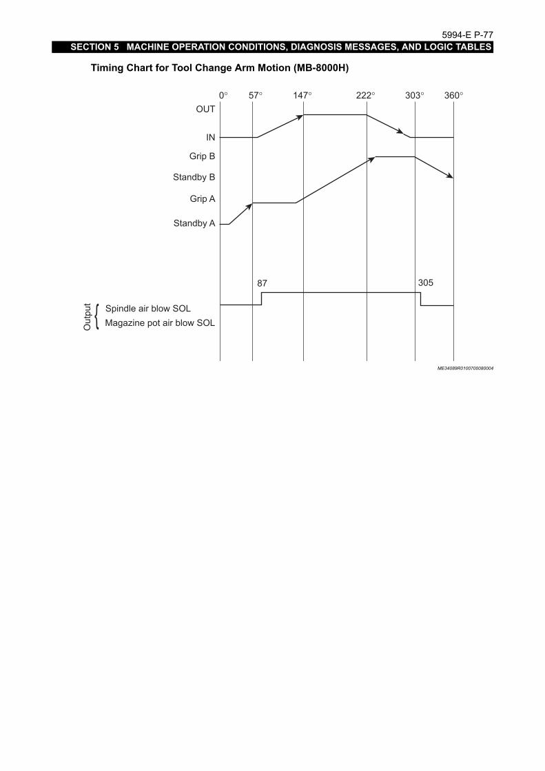
5994-E P-77SECTION 5 MACHINE OPERATION CONDITIONS, DIAGNOSIS MESSAGES, AND LOGIC TABLES
Timing Chart for Tool Change Arm Motion (MB-8000H)
ME34089R0100700080004
Out
put { Spindle air blow SOL
Magazine pot air blow SOL
OUT
IN
Grip B
Standby B
Grip A
Standby A
0° 57° 147° 222° 303° 360°
30587

5994-E P-78SECTION 5 MACHINE OPERATION CONDITIONS, DIAGNOSIS MESSAGES, AND LOGIC TABLES
4-5. APC Operation Sequence (2-Pallet Rotary)
(1) APC ready
(2) Z-axis moves to APC position (pallet position A)
(3) Pallet is unclamped.
ME34089R0100700090001
(4) APC fork rises.
ME34089R0100700090002
(5) APC fork rotates 180° (to pallet position B).
ME34089R0100700090003
2
3
A
B
4
A
B
5
A
B

5994-E P-79SECTION 5 MACHINE OPERATION CONDITIONS, DIAGNOSIS MESSAGES, AND LOGIC TABLES
(6) APC fork lowers.
ME34089R0100700090004
(7) Pallet is clamped.
ME34089R0100700090005
APC Operating Conditions
(1) A pallet is placed on the machine.
(2) Another pallet is placed on the APC. (Always use two pallets.)
(3) The pallet on the APC is located in position (APC position) by the location pin.
(4) The SETUP COMPLETION button has been pressed. (To reset the setup completion state, setthe MANUAL INT. switch on the APC operation panel to ON.)
(5) The NC operation mode is either (AUTO) or (MDI).
6
B
A
7
B
A

5994-E P-80SECTION 5 MACHINE OPERATION CONDITIONS, DIAGNOSIS MESSAGES, AND LOGIC TABLES
5. Special Operation
CAUTIONSpindle No Tool Interlock It is very dangerous to rotate the spindle while the spindle tool is notgripped by the pull stud correctly. Spindle rotation will be interlocked when incorrect gripping ofthe pull stud is detected. However, this means the spindle does not rotate when no tool is set inthe spindle. To cancel the interlock, follow the operation below.1) Manual Operation Mode
Set "1" at the MC USER PARAMETER (SPINDLE) ["No tool" interlock is made ineffective].This parameter can be cleared ("0") by turning the power off.
2) Automatic and MDI Operation ModesThe interlock can be canceled with the M command. M328......Interlock effective (modal) M329......Interlock ineffective (modal) M328 state is effective when the NC has been reset(including mode reset).

5994-E P-81SECTION 5 MACHINE OPERATION CONDITIONS, DIAGNOSIS MESSAGES, AND LOGIC TABLES
6. ATC/APC Logic Table
6-1. How to Read Logic Tables
(1) Input Logic TableATC (APC) operation sequence numbers are indicated at the Ieftmost column from the top tobottom sequentially. Input conditions corresponding to the given ATC (APC) sequence are indi-cated by circles.When the automatic tool (pallet) change cycle is carried out continuously in the automatic oper-ation mode, the sequence advances by one step when all these input conditions are met. Thatis, the table indicates the input conditions in the automatic mode operation.
(2) Output Logic TableATC (APC) operation sequence numbers are indicated at the leftmost column from the top tobottom sequentially. Outputs given at the given ATC (APC) sequence are indicated by circles.
(3) Manual Interlock TableATC (APC) operation sequence numbers are indicated at the leftmost column from the top tobottom sequentially. Interlock conditions for each ATC (APC) sequence are indicated by circles.When the automatic tool (pallet) change cycle is carried out in the 1 step advance/reversemode, the sequence advances or returns by one step when all these input conditions are met.
(4) System ConditionThe test below are used for checking the insufficient condition at the machine side whenmachine operation stops halfway or the machine fails to operate even when a command isgiven.
• A-TEST FUNCTIONThis is the function to check whether unfulfilled conditions will exist or not. The actual inputdata is compared with the test at each operation step (sequence). If they match, the stepwill advance to the next.
ME34089R0100700110001
Y1
Y2
Y3
Input Logic Table
A-test Data Actual Input Data
Input Signal
Comparison
B-testYES
Equal?NO
Alarm Display

5994-E P-82SECTION 5 MACHINE OPERATION CONDITIONS, DIAGNOSIS MESSAGES, AND LOGIC TABLES
• B-TEST FUNCTIONThis is the function to check whether there are unnecessary input conditions. The inputconditions indicated as B-test data in the Input Logic Table are checked irrespective of theoperation sequence number. That is, this interlocks ATC (APC) operation so that thesequence will not advance when operation confirmation devices such as a limit switchstays on. Note that input conditions not indicated as B-test data are not checked.When there is a discrepancy in A- and B-tests, the alarm message indicated below is dis-played on the display.3705 ALARM-C ATC system condition [judgment code]3714 ALARM-C APC system condition [judgment code]For judgment codes, consult the ATC (APC) system condition judgment code table.

5994-E P-83SECTION 5 MACHINE OPERATION CONDITIONS, DIAGNOSIS MESSAGES, AND LOGIC TABLES
(5) How the Operation Sequence Number AdvancesAt each operation sequence, input conditions are checked and when those indicated in theInput Logic Table are met, the sequence advances to the next if an ATC (APC) command ispresent. At the next sequence, outputs indicated in the Output Logic Table are given.
ME34089R0100700110002
ATC(APC) opera-tion command
Output of operation sequence number 1 ON
A-test OK?
B-test OK?
Output of operation sequence number 2 ON
Display of alarm judgment code
Display of alarm judgment code
Display of alarm judgment code
Display of alarm judgment code B-test OK?
A-test OK?
Are input con-ditions in oper-ation sequence number 1 met?
Are input con-ditions in oper-ation sequence number 2 met?
YES
NO
YES
NO
NO
YES
YES
NO

5994-E P-84SECTION 5 MACHINE OPERATION CONDITIONS, DIAGNOSIS MESSAGES, AND LOGIC TABLES
6-2. ATC/APC Logic Table
6-2-1. ATC
(1) MB-4000H,5000H (Standard magazine/Memory random)The code numbers below are displayed with the alarm C “3705 ATC system condition”.
101 Magazine pot horizontal confirmation LS is not ON.102 Magazine pot forward confirmation LS is not ON.104 Magazine pot horizontal confirmation LS is not OFF.108 Magazine pot forward confirmation LS is not OFF.140 Tool breakage detection cycle has not completed.180 Tool breakage sensor is not in the home position.204 Inside cylinder retract confirmation LS is not ON.208 Tool unclamp cylinder retract confirmation did not turn OFF.210 Spindle tool clamp confirmation is not ON.220 Spindle tool clamp confirmation did not turn OFF.240 Spindle tool unclamp confirmation did not turn OFF.280 Magazine manual interruption switch is set at ON.304 ATC shutter open confirmation LS does not work correctly.308 ATC shutter open confirmation LS is not OFF.310 ATC shutter intermediate position confirmation LS is not OFF.320 ATC shutter open confirmation LS is not ON.340 ATC shutter close confirmation LS is not ON.380 ATC shutter close confirmation LS is not OFF.401 U-axis presence confirmation LS is not ON.402 U-axis shifter advance confirmation LS is not ON.404 U-axis shifter retract confirmation LS is ON.408 U-axis connect has not completed.410 Spindle is not in the U-axis index position.501 Tool change arm is not in home position.508 Servo motor for the tool change arm rotation axis is not ready.510 APC is in the pallet cleaning sequence.520 Manual tool change cycle is in progress.540 Spindle tool present/absent statuses are inconsistent.580 Magazine tool present/absent statuses are inconsistent.601 Tool change arm rotation is not completed.680 The APC is not in the cycle start position.701 Spindle orientation is not completed.702 Spindle is not stopped.801 Active tool number writing is not completed.802 Magazine indexing is not completed.808 Dummy tool is registered at a magazine pot.880 Not in the tool storing cycle called by M64.901 Positioning to tool change position (HP1) is not completed.904 Positioning to tool change standby position (HP7) is not completed.

5994-E P-85SECTION 5 MACHINE OPERATION CONDITIONS, DIAGNOSIS MESSAGES, AND LOGIC TABLES
ME34089R0100700120001

5994-E P-86SECTION 5 MACHINE OPERATION CONDITIONS, DIAGNOSIS MESSAGES, AND LOGIC TABLES
ME34089R0100700120002

5994-E P-87SECTION 5 MACHINE OPERATION CONDITIONS, DIAGNOSIS MESSAGES, AND LOGIC TABLES
ME34089R0100700120003

5994-E P-88SECTION 5 MACHINE OPERATION CONDITIONS, DIAGNOSIS MESSAGES, AND LOGIC TABLES
ME34089R0100700120004

5994-E P-89SECTION 5 MACHINE OPERATION CONDITIONS, DIAGNOSIS MESSAGES, AND LOGIC TABLES
ME34089R0100700120005

5994-E P-90SECTION 5 MACHINE OPERATION CONDITIONS, DIAGNOSIS MESSAGES, AND LOGIC TABLES
ME34089R0100700120006

5994-E P-91SECTION 5 MACHINE OPERATION CONDITIONS, DIAGNOSIS MESSAGES, AND LOGIC TABLES
(2) MB-8000H (Standard magazine/Memory random)The code numbers below are displayed with the alarm C “3705 ATC system condition”.
101 Magazine pot spindle side confirmation LS is not ON.102 Magazine pot magazine side confirmation LS is not ON.201 Spindle clamp confirmation LS is not ON.202 Spindle unclamp confirmation LS is not ON.204 Inside cylinder retract confirmation LS is not ON.280 Magazine manual interruption switch is set at ON.320 ATC shutter open confirmation LS is not ON.340 ATC shutter close confirmation LS is not ON.380 ATC shutter close confirmation LS is not OFF.501 Tool change arm is not in home position.502 Axis change to magazine axis is not completed.504 Axis change to tool change arm axis is not completed.508 Servo motor for the tool change arm rotation axis is not ready.520 Manual tool change cycle is in progress.540 Spindle tool present/absent statuses are inconsistent.580 Magazine tool present/absent statuses are inconsistent.601 Tool change arm rotation is not completed.680 The APC is not in the cycle start position.701 Spindle orientation is not completed.702 Spindle is not stopped.704 Called cycle is not the normal tool change cycle.708 Large-diameter tool change cycle is not called(because of incomplete branch conditions for
jumping from sequence No. 10 to 17).801 Active tool number writing is not completed.802 Magazine indexing is not completed.808 Dummy tool is registered at a magazine pot.880 Not in the tool storing cycle called by M64.901 Positioning to tool change position (HP1) is not completed.

5994-E P-92SECTION 5 MACHINE OPERATION CONDITIONS, DIAGNOSIS MESSAGES, AND LOGIC TABLES
ME34089R0100700120007

5994-E P-93SECTION 5 MACHINE OPERATION CONDITIONS, DIAGNOSIS MESSAGES, AND LOGIC TABLES
ME34089R0100700120008

5994-E P-94SECTION 5 MACHINE OPERATION CONDITIONS, DIAGNOSIS MESSAGES, AND LOGIC TABLES
ME34089R0100700120009

5994-E P-95SECTION 5 MACHINE OPERATION CONDITIONS, DIAGNOSIS MESSAGES, AND LOGIC TABLES
ME34089R0100700120010

5994-E P-96SECTION 5 MACHINE OPERATION CONDITIONS, DIAGNOSIS MESSAGES, AND LOGIC TABLES
ME34089R0100700120011

5994-E P-97SECTION 5 MACHINE OPERATION CONDITIONS, DIAGNOSIS MESSAGES, AND LOGIC TABLES
ME34089R0100700120012

5994-E P-98SECTION 5 MACHINE OPERATION CONDITIONS, DIAGNOSIS MESSAGES, AND LOGIC TABLES
6-2-2. APC
The code numbers below are displayed with the alarm “3714 APC system condition”.
101 Pallet unclamp confirmation switch on the setup station side is not turned OFF.102 Pallet unclamp confirmation switch on the setup station side is not ON.104 Pallet clamp confirmation PS is not ON.108 Pallet clamp confirmation PS is not OFF.110 Pallet seated confirmation PS is not ON.120 Pallet seated confirmation PS is not OFF.140 Pallet unclamp command on the setup station side is not OFF.201 APC arm up confirmation LS is not ON.202 APC arm down confirmation LS is not ON.204 APC arm up confirmation LS is not OFF.208 APC arm down confirmation LS is not OFF210 Touch sensor retract confirmation is not input.220 Pallet unclamp confirmation PS is not OFF.240 Pallet unclamp confirmation PS is not ON.301 SETUP STATION: pallet EXIST LS is not ON.302 SETUP STATION: pallet EXIST LS is ON.304 Pallet is being transferred.308 Coupler separation on the setup station side is not complete.310 Coupler separation on the machine side is not complete.320 Coupler connection on the machine side is not complete.340 Setup station fixture clamp is not complete.380 Machine shaft clamp is not complete.401 Setup station pallet positioning pin IN confirmation switch is not ON.402 Setup station pallet positioning pin IN confirmation switch is not OFF.404 Pallet existence confirmation switch is not ON.408 Pallet existence confirmation switch is not OFF.410 PPC is operating.420 The PPC shifter is located at the standby station.440 Coupler home position confirmation is not input.480 ATC arm is not at the retract position.501 Retry cycle (Condition whether to perform pallet seating retry operation)502 Area sensor detects light shielding.580 M372 (Table call) is being executed.(Condition whether to execute the pallet cleaning cycle)701 Positioning to HP9 (Cleaning position of the pallet seating portion) is not complete.702 M372 (Table call) is not being executed.(Condition whether to execute the pallet cleaning
cycle)704 M372 (Table call) command is not being executed. Or, not the manual step operation.708 M373 (Table storage) command is not being executed. Or, not the manual step operation.801 W. LOAD FINISHED button is not pressed.880 Pallet in-position LS is not ON.904 Movement to APC position-A (HP3) is not complete.908 Movement to APC position-B (HP4) is not complete.

5994-E P-99SECTION 5 MACHINE OPERATION CONDITIONS, DIAGNOSIS MESSAGES, AND LOGIC TABLES
B01 Movement to APC arm position-A is not complete.B02 Movement to APC arm position-B is not complete.C02 B pallet setup station side APC fork down confirmation is not ON.C08 B pallet setup station side APC fork down confirmation is not OFF.

5994-E P-100SECTION 5 MACHINE OPERATION CONDITIONS, DIAGNOSIS MESSAGES, AND LOGIC TABLES
ME34089R0100700130001

5994-E P-101SECTION 5 MACHINE OPERATION CONDITIONS, DIAGNOSIS MESSAGES, AND LOGIC TABLES
ME34089R0100700130002

5994-E P-102SECTION 5 MACHINE OPERATION CONDITIONS, DIAGNOSIS MESSAGES, AND LOGIC TABLES
ME34089R0100700130003

5994-E P-103SECTION 5 MACHINE OPERATION CONDITIONS, DIAGNOSIS MESSAGES, AND LOGIC TABLES
ME34089R0100700130004

5994-E P-104SECTION 5 MACHINE OPERATION CONDITIONS, DIAGNOSIS MESSAGES, AND LOGIC TABLES
ME34089R0100700130005

5994-E P-105SECTION 5 MACHINE OPERATION CONDITIONS, DIAGNOSIS MESSAGES, AND LOGIC TABLES
ME34089R0100700130006

5994-E P-106SECTION 6 PLC MONITOR FUNCTION
SECTION 6 PLC MONITOR FUNCTION
1. Ladder Diagram Monitoring FunctionStart the D300win and display the Ladder Diagram online.
1-1. Starting Method
Procedure :
1 Press the (DIAGNOSE) key among the vertical function keys at the right end of the
screen.
ME34089R0100800020001

5994-E P-107SECTION 6 PLC MONITOR FUNCTION
2 Press the (PLC MONITOR) key in the diagnosis menu.
ME34089R0100800020002

5994-E P-108SECTION 6 PLC MONITOR FUNCTION
3 The D300win screen appears.
ME34089R0100800020003
4 Next, open a project (The project opening operation is required only when the D300win is ini-tially started.)From the menu, point to "File" and select "Open project/Unzip project."The "Open/Unzip project" dialog box appears.Specify the project name (with the extension code "mwt") and click the [Open] button.
ME34089R0100800020004

5994-E P-109SECTION 6 PLC MONITOR FUNCTION
5 The project tree appears in the project tree window (at the middle left of the screen).
ME34089R0100800020005

5994-E P-110SECTION 6 PLC MONITOR FUNCTION
1-2. Search a Project from Monitor Screen
Perform global search with the label name that you want to monitor online.
Procedure :
1 From the menu, point to Edit and select Global Find. The Find/Replace dialog box appears.
ME34089R0100800030001
2 Select the "Global Find" tab and enter a label name in the "Find What" input field. Set a check-mark at "Code work sheets" in the Selection column. Then, click the [Find Next] button.
ME34089R0100800030002
3 When searching a coil output, select the "Global Find LD Objects" tab and enter a label namein the "Text" input field. Select a coil at "Object" input field. The click [Find Next] button.

5994-E P-111SECTION 6 PLC MONITOR FUNCTION
4 The program work sheet that includes the specified label opens.
ME34089R0100800030003

5994-E P-112SECTION 6 PLC MONITOR FUNCTION
5 Click "Online" in the menu and select "Debug." The program work sheet is displayed online,showing the state of the program being executed.
ME34089R0100800030004
The bit data shows ON symbol in red and OFF symbol in blue.

5994-E P-113SECTION 6 PLC MONITOR FUNCTION
2. Logic Analyzer FunctionStart the D300win. The logic analyzer function samples the data specified with the labels in thebuffer at regular intervals and displays the sampling results on the screen.
2-1. Start Method
Perform the following operation during online monitoring of a ladder chart. For the procedure ofmonitoring a ladder chart online, refer to 1. "Ladder Diagram Monitoring Function."
Procedure :
1 Click "View" in the menu and select "Logic analyzer" to open the Logic analyzer window.The logic analyzer window has the C_IPC:R_IPC tab and is located at the lower left of thescreen.
ME34089R0100800050001

5994-E P-114SECTION 6 PLC MONITOR FUNCTION
2 Press Esc key while pressing the Ctrl key to display the task bar.
Click the "Event Select" icon on the task bar to change it to the right-click mode .Click the variable that you want to monitor on the work sheet.Select "Add to Logicanalyzer" from the displayed menu.
ME34089R0100800050002

5994-E P-115SECTION 6 PLC MONITOR FUNCTION
3 Click "Online" in the menu, and select "Logic analyzer" and then "Trigger condition." The trig-ger configuration screen opens. Set the start conditions and the data collecting timing.
ME34089R0100800050003
Sampling
Trigger conditions
Data collection
Pre-recording cycles : Set the number of sampling times executed before the trigger conditions are met.
Post-recording cycles : Set the number of sampling times executed after the trigger conditions are met.
1. variable : Select a variable used as a trigger from the registered variables.Operator : Set the trigger conditions. If only one variable is selected, either RE
(rising edge) or FE (falling edge) can be selected.2. variable : The variable 2 can be selected if you set an equality or inequality con-
ditions at the operator.
Synchronous with task: Be sure to select this function. Select either ev2_PPLH or ev3_PPLM as the synchronizing task.

5994-E P-116SECTION 6 PLC MONITOR FUNCTION
2-2. Data Sampling
Procedure :
1 Click Online in the menu, and select "Logic analyzer" and then "Start recording." On comple-tion of data recording, the sampled results are displayed in the logic analyzer window.
ME34089R0100800060001
To suspend data recording, click "Online" in the menu, select the "Logic analyzer" and then"Stop recording."

5994-E P-117SECTION 7 PLC PROGRAM INSTRUCTIONS
SECTION 7 PLC PROGRAM INSTRUCTIONS
1. Outline of PLC Program InstructionsThis section describes the instructions used in PLC programs which are displayed in the laddermonitor.

5994-E P-118SECTION 7 PLC PROGRAM INSTRUCTIONS
2. Programming Languages
2-1. Types of Programming Languages
ME34089R0100900020001

5994-E P-119SECTION 7 PLC PROGRAM INSTRUCTIONS
2-2. IL Language
ME34089R0100900030001

5994-E P-120SECTION 7 PLC PROGRAM INSTRUCTIONS
ME34089R0100900030002

5994-E P-121SECTION 7 PLC PROGRAM INSTRUCTIONS
ME34089R0100900030003

5994-E P-122SECTION 7 PLC PROGRAM INSTRUCTIONS
ME34089R0100900030004

5994-E P-123SECTION 7 PLC PROGRAM INSTRUCTIONS
ME34089R0100900030005

5994-E P-124SECTION 7 PLC PROGRAM INSTRUCTIONS
ME34089R0100900030006

5994-E P-125SECTION 7 PLC PROGRAM INSTRUCTIONS
ME34089R0100900030007

5994-E P-126SECTION 7 PLC PROGRAM INSTRUCTIONS
ME34089R0100900030008

5994-E P-127SECTION 7 PLC PROGRAM INSTRUCTIONS
ME34089R0100900030009

5994-E P-128SECTION 7 PLC PROGRAM INSTRUCTIONS
ME34089R0100900030010

5994-E P-129SECTION 7 PLC PROGRAM INSTRUCTIONS
ME34089R0100900030011

5994-E P-130SECTION 7 PLC PROGRAM INSTRUCTIONS
ME34089R0100900030012

5994-E P-131SECTION 7 PLC PROGRAM INSTRUCTIONS
ME34089R0100900030013

5994-E P-132SECTION 7 PLC PROGRAM INSTRUCTIONS
ME34089R0100900030014

5994-E P-133SECTION 7 PLC PROGRAM INSTRUCTIONS
ME34089R0100900030015

5994-E P-134SECTION 7 PLC PROGRAM INSTRUCTIONS
ME34089R0100900030016

5994-E P-135SECTION 7 PLC PROGRAM INSTRUCTIONS
ME34089R0100900030017

5994-E P-136SECTION 7 PLC PROGRAM INSTRUCTIONS
ME34089R0100900030018

5994-E P-137SECTION 7 PLC PROGRAM INSTRUCTIONS
ME34089R0100900030019

5994-E P-138SECTION 7 PLC PROGRAM INSTRUCTIONS
ME34089R0100900030020

5994-E P-139SECTION 7 PLC PROGRAM INSTRUCTIONS
ME34089R0100900030021

5994-E P-140SECTION 7 PLC PROGRAM INSTRUCTIONS
ME34089R0100900030022

5994-E P-141SECTION 7 PLC PROGRAM INSTRUCTIONS
ME34089R0100900030023

5994-E P-142SECTION 7 PLC PROGRAM INSTRUCTIONS
ME34089R0100900030024

5994-E P-143SECTION 7 PLC PROGRAM INSTRUCTIONS
ME34089R0100900030025

5994-E P-144SECTION 7 PLC PROGRAM INSTRUCTIONS
ME34089R0100900030026

5994-E P-145SECTION 7 PLC PROGRAM INSTRUCTIONS
ME34089R0100900030027

5994-E P-146SECTION 7 PLC PROGRAM INSTRUCTIONS
2-3. ST Language
ME34089R0100900040001

5994-E P-147SECTION 7 PLC PROGRAM INSTRUCTIONS
ME34089R0100900040002

5994-E P-148SECTION 7 PLC PROGRAM INSTRUCTIONS
ME34089R0100900040003

5994-E P-149SECTION 7 PLC PROGRAM INSTRUCTIONS
ME34089R0100900040004

5994-E P-150SECTION 7 PLC PROGRAM INSTRUCTIONS
ME34089R0100900040005

5994-E P-151SECTION 7 PLC PROGRAM INSTRUCTIONS
ME34089R0100900040006

5994-E P-152SECTION 7 PLC PROGRAM INSTRUCTIONS
2-4. LD Language
ME34089R0100900050001

5994-E P-153SECTION 7 PLC PROGRAM INSTRUCTIONS
ME34089R0100900050002

5994-E P-154SECTION 7 PLC PROGRAM INSTRUCTIONS
ME34089R0100900050003

5994-E P-155SECTION 7 PLC PROGRAM INSTRUCTIONS
ME34089R0100900050004

5994-E P-156SECTION 7 PLC PROGRAM INSTRUCTIONS
2-5. FBD Language
ME34089R0100900060001

5994-E P-157SECTION 7 PLC PROGRAM INSTRUCTIONS
ME34089R0100900060002

5994-E P-158SECTION 7 PLC PROGRAM INSTRUCTIONS
ME34089R0100900060003

5994-E P-159SECTION 7 PLC PROGRAM INSTRUCTIONS
ME34089R0100900060004

5994-E P-160SECTION 7 PLC PROGRAM INSTRUCTIONS
ME34089R0100900060005

5994-E P-161SECTION 7 PLC PROGRAM INSTRUCTIONS
ME34089R0100900060006

5994-E P-162SECTION 7 PLC PROGRAM INSTRUCTIONS
ME34089R0100900060007

5994-E P-163SECTION 7 PLC PROGRAM INSTRUCTIONS
ME34089R0100900060008

5994-E P-164SECTION 7 PLC PROGRAM INSTRUCTIONS
ME34089R0100900060009

5994-E P-165SECTION 7 PLC PROGRAM INSTRUCTIONS
ME34089R0100900060010

5994-E P-166SECTION 7 PLC PROGRAM INSTRUCTIONS
ME34089R0100900060011

5994-E P-167SECTION 7 PLC PROGRAM INSTRUCTIONS
ME34089R0100900060012

5994-E P-168SECTION 7 PLC PROGRAM INSTRUCTIONS
ME34089R0100900060013

5994-E P-169SECTION 7 PLC PROGRAM INSTRUCTIONS
ME34089R0100900060014

5994-E P-170SECTION 7 PLC PROGRAM INSTRUCTIONS
ME34089R0100900060015

5994-E P-171SECTION 7 PLC PROGRAM INSTRUCTIONS
ME34089R0100900060016

5994-E P-172SECTION 7 PLC PROGRAM INSTRUCTIONS
ME34089R0100900060017

5994-E P-173SECTION 7 PLC PROGRAM INSTRUCTIONS
ME34089R0100900060018

5994-E P-174SECTION 7 PLC PROGRAM INSTRUCTIONS
ME34089R0100900060019

5994-E P-175SECTION 7 PLC PROGRAM INSTRUCTIONS
ME34089R0100900060020

5994-E P-176SECTION 7 PLC PROGRAM INSTRUCTIONS
ME34089R0100900060021

5994-E P-177SECTION 7 PLC PROGRAM INSTRUCTIONS
ME34089R0100900060022

5994-E P-178SECTION 7 PLC PROGRAM INSTRUCTIONS
ME34089R0100900060023

5994-E P-179SECTION 7 PLC PROGRAM INSTRUCTIONS
ME34089R0100900060024

5994-E P-180SECTION 7 PLC PROGRAM INSTRUCTIONS
ME34089R0100900060025

5994-E P-181SECTION 7 PLC PROGRAM INSTRUCTIONS
ME34089R0100900060026

5994-E P-182SECTION 7 PLC PROGRAM INSTRUCTIONS
ME34089R0100900060027

5994-E P-183SECTION 7 PLC PROGRAM INSTRUCTIONS
ME34089R0100900060028

5994-E P-184SECTION 7 PLC PROGRAM INSTRUCTIONS
ME34089R0100900060029

5994-E P-185SECTION 7 PLC PROGRAM INSTRUCTIONS
ME34089R0100900060030

5994-E P-186SECTION 7 PLC PROGRAM INSTRUCTIONS
ME34089R0100900060031

5994-E P-187SECTION 7 PLC PROGRAM INSTRUCTIONS
ME34089R0100900060032

5994-E P-188SECTION 7 PLC PROGRAM INSTRUCTIONS
ME34089R0100900060033

5994-E P-189SECTION 8 MAINTENANCE PART CHANGE
SECTION 8 MAINTENANCE PART CHANGE
1. Battery ChangeWhen the battery life has expired, change the battery with a new one.The OSP uses three types of batteries:
• Coin battery
• UPS battery
• Relocation detection unit battery
1-1. Battery Life Warning(1) Coin battery
If the battery life detection function (refer to SECTION 8, 1-3) causes the alarm D 4057 “Batteryis out of life” or the Windows clock is too slow, the coin battery may have expired its service life.Change the battery.
[Coin battery type]
Note
[Supplement]
OSP type E part No. Type No. Battery type Nominal voltage
Nominal capacity
OSP-P200MA E5503-653-001 BR2032 Coin type lithium battery 3V 190mAh
Commercially available coin battery can be used.Select the type, BR2032 or CR2032 or equivalent.
Even if the coin battery life has run out, the machine can be operated as usual.

5994-E P-190SECTION 8 MAINTENANCE PART CHANGE
(2) UPS battery
• Self dischargeIf the machine is left unused for a long time (about six months), the battery discharges elec-tricity by itself. As a result, the power unit may turn on the BAT lamp. This is not a powerunit failure. Turn on the main breaker to charge the battery for 30 minutes or longer. Then,turn off main breaker and turn it back on. If the BAT is still lit, the battery life has expired.Change the battery.
• Battery lifeIf the battery life detection function (refer to SECTION 8, 1-3) generates an alarm D 4057“Battery is out of life,” the UPS battery may have expired its service life. Change the bat-tery.
[UPS battery type]
[Supplement]
Note
(3) Relocation detection unit batteryChange batteries when the alarm D 4057 "Battery is out of life" 1 appears, which caused by thebattery life detection function (refer to 1-3 of Section 8) to indicate expired battery life of therelocation detection unit.
[Specifications of relocation detection unit battery]
OSP type E part No. Type No Battery type Nominal voltage
Nominal capacity
OSP-P200MA E5503-07E-001 8HR-4/3FAUPC NiMH battery pack
9.6V 3200mAh
The power ON switch is invalid in activating the NC unit while the [BAT] lamp is lit. Change the UPS battery. If you need to turn on the power before new UPS battery is prepared,turn on the power forcibly. Refer to the trouble shooting related to the power on/off in Section 3.
Turning the NC on by the forcible power on operation may cause the data loss in case of an elec-tricity failure.
OSP type E part No. Type No. Battery type Nominal voltage
Nominal capacity
OSP-P200MA E5503-702-003 CR17450 Lithium-manga-nese dioxide cylindrical cell
3V 2600mAh× 2

5994-E P-191SECTION 8 MAINTENANCE PART CHANGE
1-2. Battery Change ProcedureCoin battery
Procedure :
1 Turn off the power and the main breaker.
2 Open the back cover of the operation panel.
3 Change the coin battery mounted in the panel computer.
4 Turn the power on again to re-set the date and time in the built-in clock.(Refer to the Reference Manual for settings.)
ME34089R0101000030001
Coin battery

5994-E P-192SECTION 8 MAINTENANCE PART CHANGE
ME34089R0101000030002
+ pole
[How to remove the coin battery]
[How to set the coin battery]
Push the clip to the side.The coin battery pops up.
1.
+ pole
+ pole
Remove the coin battery, being careful not to drop it.
2.
Insert the coin battery into the battery holder at a 45° angle and press down.
1.
The coin battery clips into the battery holder.
2.

5994-E P-193SECTION 8 MAINTENANCE PART CHANGE
UPS battery
Procedure :
1 Turn off the power and the main breaker.
2 Open the back cover of the operation panel.
3 Change the UPS battery.
4 Turn on the operation power and update the date of battery change. (Refer to SECTION 8, “1-3 (1) Updating the date of battery change.”)

5994-E P-194SECTION 8 MAINTENANCE PART CHANGE
[UPS battery removing method]
(1) Remove the UPS battery cable from the UPS power unit.
ME34089R0101000030003
Horizontal type
Vertical type (keyboard)
UPS battery
UPS battery
UPS battery cable connector

5994-E P-195SECTION 8 MAINTENANCE PART CHANGE
(2) Loosen the cover sheet metal fixing screws.
(3) Remove the cover sheet metal and take out the UPS battery.
ME34089R0101000030004
[UPS battery installation method]
(1) Insert a new UPS battery and attach the cover sheet metal.
(2) Tighten the cover sheet metal fixing screws.
ME34089R0101000030005
Cover sheet metal fixing screws 4 places
Cover sheet metal fixing screws 4 places

5994-E P-196SECTION 8 MAINTENANCE PART CHANGE
(3) Connect the UPS battery cable to the UPS power unit.
ME34089R0101000030006
Horizontal type
Vertical type (keyboard)
UPS battery
UPS battery
UPS battery cable connector

5994-E P-197SECTION 8 MAINTENANCE PART CHANGE
Relocation Detection Unit Battery
Procedure :
1 Turn off the operation power and the main breaker.
2 Open the control box door.
3 Replace the batteries for relocation detection unit.
ME34089R0101000030007
Two battery cable connectors are provided for the relocation detection unit battery holder. Changebatteries while either of the two battery cable connectors are connected the relocation detectionunit.
NoteIf the batteries are changed with all of the two battery cable connectors disconnected simulta-neously while the main breaker is turned off, the relocation detection function is activated when thepower is turned on again after battery change. Entering password is needed to cancel the reloca-tion detection status. Thus, make sure to change batteries while either of the two battery cableconnectors are connected to the unit. However, if the main breaker is turned on, the relocationdetection function will not be activated even though batteries are changed with all of the two bat-tery cable connectors disconnected.
Relocation detection unit battery
Relocation detection unitSSU-RD2

5994-E P-198SECTION 8 MAINTENANCE PART CHANGE
[How to change relocation detection unit batteries]
(1) Remove the battery holder with no battery mounted and mount a new battery pack in the bat-tery holder.
ME34089R0101000030008
Battery holder with no battery mounted
Battery pack 2 sets

5994-E P-199SECTION 8 MAINTENANCE PART CHANGE
(2) Attach the battery holder with a new battery pack mounted to the relocation detection unit.
ME34089R0101000030009
(3) Disconnect one battery connector cable of the old battery holder and connect one battery con-nector cable of the new battery holder.
ME34089R0101000030010

5994-E P-200SECTION 8 MAINTENANCE PART CHANGE
(4) Disconnect remaining battery connector cable of the old battery holder and connect batteryconnector cable of the new battery holder.
ME34089R0101000030011
(5) Remove the old battery holder and the old battery pack. Attach the battery holder without bat-tery pack to the relocation detection unit.
ME34089R0101000030012

5994-E P-201SECTION 8 MAINTENANCE PART CHANGE
1-3. Battery Life Detection FunctionThe OSP-P200MA have the battery life detection function. The following alarm appears when finishof battery service life is detected. The alarm is caused when three years have passed for UPS bat-tery and coin battery, and when voltage reduction is detected for the relocation detection unit battery.
4057 Battery is out of lifeThe UPS battery, the coin battery, or the relocation detection unit battery has finished theirservice life.[Index]None[Character-string]None[Code]None: UPS battery, coin battery1 : Battery for the relocation detection unit[Measure to Take]Change the UPS batteries, the coin batteries or the relocation detection unit batteries follow-ing the subscription of the code.
If batteries are not changed when the alarm appears, the system may not be protected in the caseof sudden power failure or entering of password may be needed to cancel the relocation detectionstatus.
(1) Updating the Date of Battery ChangeSetting of date when batteries are changed is necessary after changing UPS batteries or coinbatteries. The followings are the procedures of setting date when batteries are changed. Theprocedures are not required of changing relocation detection unit batteries.
a. Select the parameter setting mode.
b. Press [F8] (DISPLAY CHANGE) and select the BATTERY DATA screen.
c. Press [F1] (SET) and enter the date of battery change (in the format of YYYY/MM/DD).Then, press the WRITE key. If you press the WRITE key without entering the date, today'sdate is set.
CAUTIONThe BATTERY DATA screen cannot be displayed without changing the initial setting. To displaythe screen, follow the steps below:1) Press [F8] (DISPLAY CHANGE).2) Press the extension key and select [F1] (CHANGE MENU).3) Turn on the Battery data checkbox.

5994-E P-202SECTION 8 MAINTENANCE PART CHANGE
ME34089R0101000040001
ME34089R0101000040002

5994-E P-203SECTION 8 MAINTENANCE PART CHANGE
(2) Input ErrorIn case of wrong format other than “YYYY/MM/DD”, error message is displayed and data inputis denied. Press [F8] (OK) to reset the error message.
ME34089R0101000040003

5994-E P-204SECTION 8 MAINTENANCE PART CHANGE
2. Changing Fan MotorChange the fan motor periodically because they are consumable parts.
(1) CPU fan motor
2-1. Fan Motor Life Warning
(1) CPU fan motorThe machine has the function for detecting stoppage of the fan.Change the CPU fan motor on occurrence of the following alarm:Alarm B 2060 Fan motor error on panel computer unit 10101Alarm D 4085 Fan motor error on panel computer unit 10101
[CPU fan motor type]
OSP type E part No. TypeOSP-P200MA E1310-951-001 N8368-10098SP04 PNC3-CPUFAN

5994-E P-205SECTION 8 MAINTENANCE PART CHANGE
2-2. Battery Change ProcedureCPU fan motor
Procedure :
1 Turn off the operation power and the main breaker.
2 Open the back cover of the operation panel.
3 Change the CPU fan motor mounted in the panel computer.
ME34089R0101000070001
CPU fan motor

5994-E P-206SECTION 8 MAINTENANCE PART CHANGE
[Method of removing the CPU fan motor]
(1) Disconnect the CPU fan motor cable from the connector (CPU FAN).
ME34089R0101000070002
(2) Remove the two screws.
ME34089R0101000070003
CPU fan motor cable connector
Remove the two screws.

5994-E P-207SECTION 8 MAINTENANCE PART CHANGE
(3) Remove the fan cover and the CPU fan motor.
ME34089R0101000070004
(Note) Keep the fan cover and the screws. They will be reused.
[Method of installing the CPU fan motor]To reinstall, follow the removal procedure in reverse order.
ME34089R0101000070005
CPU FAN
2 screws
Fan cover
Secure the two screws.
Connect the CPU fan motor cable.

5994-E P-208SECTION 8 MAINTENANCE PART CHANGE
3. Replacing the HDDWhen the HDD reaches the end of its service life, it must be replaced with a new one.
3-1. HDD End of Life Warning
If Alarm D 4059 “Backup file illegal” is triggered, contact the Okuma service department to requestHDD replacement.
[HDD type]
[Supplement]
OSP type E part No. TypeOSP-P200MA E0241-951-001 N8368-10098SP06 PNC3-HDDUNIT
The HDD may have reached the end of its service life. Before the HDD fails, making it impossibleto read data, contact the Okuma service department to request replacement.

5994-E P-209SECTION 9 APPENDIX
SECTION 9 APPENDIX
1. ATC Device Layout (MB-4000H/5000H)
ME34089R0101100010001
Device No. Device NameEMA MA-axis encoderMMA MA-axis drive motorYBMA MA-axis brakeETS TS-axis encoderMTS TS-axis drive motorYBTS TS-axis brakeSQ21A MG pot horizontallySQ22A MG pot forwardSQ23A ATC belt breakage detectionSQ92 ATC door closeSQ93 ATC door openYV25 MG pot forwardYV26 MG pot horizontallyYV71 ATC door closeYV72 ATC door open

5994-E P-210SECTION 9 APPENDIX
2. Machine Device Layout (MB-4000H)
ME34089R0101100020001

5994-E P-211SECTION 9 APPENDIX
Device No. Device Name Device No. Device NameEX X-axis encoder SP1P Pallet seatingEY Y-axis encoder SP4P Pallet clamp pressure confirmationEZ Z-axis encoder SP6P (1°)
SP8P (NC)Table clamp pressure normal
EB B-axis encoder SP5P Dry air pressure normalEPA PA axis encoder SP10A Oil air pressure rise detectionMX X-axis drive motor SL1 Hydraulic unit oil level normalMY Y-axis drive motor YA9 Operator door interlock switchMZ Z-axis drive motor YA19A Magazine door interlock switchMB B-axis drive motor YA29A APC door interlock switchMPA PA axis drive motor YV1 Table unclampM1 Spindle drive motor YV2 Pallet unclampYBY Y-axis brake YV126 Pallet seating detection air blowPG1 Spindle pulse generator YV4 Spindle air blowSQ1P Pallet presence YV5 Attachment air blowSQ2P Pallet in-position YV6 Chip air blow nozzleSQ3P APC fork UP YV7 Chip air blow adaptorSQ10P APC fork DOWN (A pallet) YV22 Manual tool unclampSQ11P APC fork DOWN (B pallet) YV1P APC fork UPSQ4 Tool clamp confirmation YV2P APC fork DOWNSQ5 Unclamp cylinder advance YV1T Touch sensor unit UPSQ6 Unclamp cylinder retract YV2T Touch sensor unit DOWNSQ9 Operator door interlock switch YV3T Touch sensor air blowSQ19A Magazine door interlock switch YV81 Coolant NozzleSQ29A APC door interlock switch YV84 Through Draw UpSQ41 Clamp without tool YVBA Oil air lubricationSQ2T Touch sensor unit UP YVBA1 Through-spindle air blowSQ3T Touch sensor unit DOWN YVBA3 Air supply for oil air lubricationSQ94 Table DOWN HLPL Spot lightSQ95 Table UP HLPL2 Fluorescent lamp
HLPL2A Fluorescent lamp

5994-E P-212SECTION 9 APPENDIX
3. Machine Device Layout (MB-5000H)
ME34089R0101100030001

5994-E P-213SECTION 9 APPENDIX
Device No. Device Name Device No. Device NameEX X-axis encoder SP1P Pallet seatingEY Y-axis encoder SP4P Pallet clamp pressure confirmationEZ Z-axis encoder SP6P (1°)
SP8P (NC)Table clamp pressure normal
EB B-axis encoder SP5P Dry air pressure normalEPA PA axis encoder SP10A Oil air pressure rise detectionMX X-axis drive motor SL1 Hydraulic unit oil level normalMY Y-axis drive motor YA9 Operator door interlock switchMZ Z-axis drive motor YA19A Magazine door interlock switchMB B-axis drive motor YA29A APC door interlock switchMPA PA axis drive motor YV1 Table unclampM1 Spindle drive motor YV2 Pallet unclampYBY Y-axis brake YV126 Pallet seating detection air blowPG1 Spindle pulse generator YV4 Spindle air blowSQ1P Pallet presence YV5 Attachment air blowSQ2P Pallet in-position YV6 Chip air blow nozzleSQ3P APC fork UP YV7 Chip air blow adaptorSQ4P APC fork DOWN YV22 Manual tool unclampSQ4 Tool clamp confirmation YV1P APC fork UPSQ5 Unclamp cylinder advance YV2P APC fork DOWNSQ6 Unclamp cylinder retract YV1T Touch sensor unit UPSQ9 Operator door interlock switch YV2T Touch sensor unit DOWNSQ19A Magazine door interlock switch YV3T Touch sensor air blowSQ29A APC door interlock switch YVBA Oil air lubricationSQ41 Clamp without tool YVBA1 Through-spindle air blowSQ2T Touch sensor unit UP YVBA3 Air supply for oil air lubricationSQ3T Touch sensor unit DOWN HLPL Spot lightSQ94 Table DOWN HLPL2 Fluorescent lampSQ95 Table UP HLPL2A Fluorescent lampSQ14P A/B pallet determination

5994-E P-214SECTION 9 APPENDIX
4. ATC Device Layout (MB-8000H)
ME34089R0101100040001
Device No. Device NameEMA MA axis encoderMMA MA axis drive motorYBMA MA axis brakeETS TS axis encoderMTS TS axis drive motorYBTS TS axis brakeSQ10A Tool presence in MG potSQ13A Pot on RS side confirmationSQ14A MG pot on MG sideSQ92 ATC door closeSQ93 ATC door openYV18 MG pot rotating positionYV19 MG pot tool change positionYV20 MG pot air blowYV71 ATC door closeYV72 ATC door open

5994-E P-215SECTION 9 APPENDIX
5. Machine Device Layout (MB-8000H)
ME34089R0101100050001

5994-E P-216SECTION 9 APPENDIX
Device No. Device Name Device No. Device NameEX X-axis encoder SP1P Pallet seatingEYM Y-axis (master axis) encoder SP4P Pallet clamp pressure confirmationEYS Y-axis (slave axis) encoder SP6P (1°)
SP8P (NC)Table clamp pressure normal
EZ Z-axis encoder SP5P Dry air pressure normalEB B-axis encoder SP10A Oil air pressure rise detectionEPA PA axis encoder SL1 Hydraulic unit oil level normalMX X-axis drive motor YA9 Operator door interlock switchMYM Y-axis (master axis) drive motor YA19A Magazine door interlock switchMYS Y-axis (slave axis) drive motor YA29A APC door interlock switchMZ Z-axis drive motor YV1 Table unclampMB B-axis drive motor YV2 Pallet unclampMPA PA axis drive motor YV126 Pallet seating detection air blowM1 Spindle drive motor YV4 Spindle air blowYBYM Y-axis (master axis) brake YV5 Attachment air blowYBYS Y-axis (slave axis) brake YV6 Chip air blow nozzlePG1 Spindle pulse generator YV7 Chip air blow adaptorSQ1P Pallet presence YV22 Manual tool unclampSQ2P Pallet in-position YV1P APC fork UPSQ3P APC fork UP YV2P APC fork DOWNSQ10P APC fork DOWN (A pallet) YV22P Pallet Fork Air BlowSQ11P APC fork DOWN (B pallet) YV1T Touch sensor unit UPSQ4 Tool clamp confirmation YV2T Touch sensor unit DOWNSQ5 Unclamp cylinder advance YV3T Touch sensor air blowSQ6 Unclamp cylinder retract YVBA Oil air lubricationSQ9 Operator door interlock switch YVBA1 Through-spindle air blowSQ19A Magazine door interlock switch YVBA3 Air supply for oil air lubricationSQ29A APC door interlock switch YVBA4 Labyrinth Air BlowSQ41 Clamp without tool HLPL Spot lightSQ2T Touch sensor unit UP HLPL2 Fluorescent lampSQ3T Touch sensor unit DOWN HLPL2A Fluorescent lampSQ94 Table DOWNSQ95 Table UP

5994-E P-217SECTION 9 APPENDIX
6. MA-500HII/600HII Magazine Device Layout
ME34089R0101100060001
Device No. Device NameEMA MA axis encoderMMA MA axis drive motorYBMA MA axis brakeETS TS axis encoderMTS TS axis drive motorYBTS TS axis brakeSQ10A Tool presence in MG potSQ13A MG pot spindle sideSQ14A MG pot on MG sideSQ23A ATC belt breakage detectionSQ24A MG belt breakageSQ25A MG unclampSQ92 ATC door closeSQ93 ATC door openYV18 MG pot rotating positionYV19 MG pot tool change positionYV20 MG pot air blowYV67 MG lock pin OUTYV71 ATC door closeYV72 ATC door open

5994-E P-218SECTION 9 APPENDIX
7. MA-500HII Device Layout
ME34089R0101100070001

5994-E P-219SECTION 9 APPENDIX
Device No. Device Name Device No. Device NameEX X-axis encoder SP1P Pallet seatingEYM Y-axis (master axis) encoder SP4P Pallet clamp pressure confirmationEYS Y-axis (slave axis) encoder SP6P (1°)
SP8P (NC)Table clamp pressure normal
EZ Z-axis encoder SP5P Dry air pressure normalEB B-axis encoder SP10A Oil air pressure rise detectionEPA PA axis encoder SL1 Hydraulic unit oil level normalMX X-axis drive motor YA9 Operator door interlock switchMYM Y-axis (master axis) drive motor YA19A Magazine door interlock switchMYS Y-axis (slave axis) drive motor YA29A APC door interlock switchMZ Z-axis drive motor YV1 Table unclampMB B-axis drive motor YV2 Pallet unclampMPA PA axis drive motor YV126 Pallet seating detection air blowM1 Spindle drive motor YV4 Spindle air blowYBYM Y-axis (master axis) brake YV5 Attachment air blowYBYS Y-axis (slave axis) brake YV6 Chip air blow nozzlePG1 Spindle pulse generator YV7 Chip air blow adaptorSQ1P Pallet presence YV22 Manual tool unclampSQ2P Pallet in-position YV1P APC fork UPSQ3P APC fork UP YV2P APC fork DOWNSQ10P APC fork DOWN (A pallet) YV22P Pallet Fork Air BlowSQ11P APC fork DOWN (B pallet) YV1T Touch sensor unit UPSQ4 Tool clamp confirmation YV2T Touch sensor unit DOWNSQ5 Unclamp cylinder advance YV3T Touch sensor air blowSQ6 Unclamp cylinder retract YVBA Oil air lubricationSQ9 Operator door interlock switch YVBA1 Through-spindle air blowSQ19A Magazine door interlock switch YVBA3 Air supply for oil air lubricationSQ29A APC door interlock switch HLPL Spot lightSQ41 Clamp without tool HLPL2 LED lampSQ2T Touch sensor unit UPSQ3T Touch sensor unit DOWNSQ94 Table DOWNSQ95 Table UP

5994-E P-220SECTION 9 APPENDIX
8. MA-600HII Device Layout
ME34089R0101100080001

5994-E P-221SECTION 9 APPENDIX
Device No. Device Name Device No. Device NameEX X-axis encoder SP1P Pallet seatingEYM Y-axis (master axis) encoder SP4P Pallet clamp pressure confirmationEYS Y-axis (slave axis) encoder SP6P (1°)
SP8P (NC)Table clamp pressure normal
EZ Z-axis encoder SP5P Dry air pressure normalEB B-axis encoder SP10A Oil air pressure rise detectionEPA PA axis encoder SL1 Hydraulic unit oil level normalMX X-axis drive motor YA9 Operator door interlock switchMYM Y-axis (master axis) drive motor YA19A Magazine door interlock switchMYS Y-axis (slave axis) drive motor YA29A APC door interlock switchMZ Z-axis drive motor YV1 Table unclampMB B-axis drive motor YV2 Pallet unclampMPA PA axis drive motor YV126 Pallet seating detection air blowM1 Spindle drive motor YV4 Spindle air blowYBYM Y-axis (master axis) brake YV5 Attachment air blowYBYS Y-axis (slave axis) brake YV6 Chip air blow nozzlePG1 Spindle pulse generator YV7 Chip air blow adaptorSQ1P Pallet presence YV22 Manual tool unclampSQ2P Pallet in-position YV1P APC fork UPSQ3P APC fork UP YV2P APC fork DOWNSQ10P APC fork DOWN (A pallet) YV22P Pallet Fork Air BlowSQ11P APC fork DOWN (B pallet) YV1T Touch sensor unit UPSQ4 Tool clamp confirmation YV2T Touch sensor unit DOWNSQ5 Unclamp cylinder advance YV3T Touch sensor air blowSQ6 Unclamp cylinder retract YVBA Oil air lubricationSQ9 Operator door interlock switch YVBA1 Through-spindle air blowSQ19A Magazine door interlock switch YVBA3 Air supply for oil air lubricationSQ29A APC door interlock switch HLPL Spot lightSQ41 Clamp without tool HLPL2 LED lampSQ2T Touch sensor unit UPSQ3T Touch sensor unit DOWNSQ94 Table DOWNSQ95 Table UP

5994-E P-222SECTION 9 APPENDIX
9. Control Device Layout (MB-4000H/5000H)
ME34089R0101100090001

5994-E P-223SECTION 9 APPENDIX
10. Control Device Layout (MB-8000H/MA-500HII/600HII)
ME34089R0101100100001

LIST OF PUBLICATIONS
Publication No. Date Edition
5994-E January 2012 1st
This manual may be at variance with the actual product due to specification or design changes.Please also note that specifications are subject to change without notice.If you require clarification or further explanation of any point in this manual, please contact your OKUMA representative.