ME-212-F KINEMATICS OF MACHINES LAB List of Experiments … manual/KOM lab.pdf · ME-212-F...
26
ME-212-F KINEMATICS OF MACHINES LAB List of Experiments 1. To study various types of Links, Pairs, Chain and Mechanism 2. To study inversion of Four Bar Mechanism, Single Slider Crank Chain Mechanism and Double Slider Crank Chain Mechanism. 3. To study velocity diagram for Slider Crank Mechanism. 4. To study various kinds of belts drives. 5. To study and find coefficient of friction between belt and pulley. 6. To study various types of Cam and Follower arrangement. 7. To plot follower displacement Vs cam rotation graph for various cam follower arrangement. 8. To study the working of Screw Jack and determine its efficiency. 9. To study Different types of Gears. 10.To study Different types of Gear Trains.
Transcript of ME-212-F KINEMATICS OF MACHINES LAB List of Experiments … manual/KOM lab.pdf · ME-212-F...

ME-212-F KINEMATICS OF MACHINES LAB
List of Experiments
1. To study various types of Links, Pairs, Chain and Mechanism
2. To study inversion of Four Bar Mechanism, Single Slider Crank Chain Mechanism and
Double Slider Crank Chain Mechanism.
3. To study velocity diagram for Slider Crank Mechanism.
4. To study various kinds of belts drives.
5. To study and find coefficient of friction between belt and pulley.
6. To study various types of Cam and Follower arrangement.
7. To plot follower displacement Vs cam rotation graph for various cam follower
arrangement.
8. To study the working of Screw Jack and determine its efficiency.
9. To study Different types of Gears.
10. To study Different types of Gear Trains.

Experiment No.1
Aim: - To study various types of links, pairs, chain and mechanism.
Theory:-
Introduction
A machine consists of a number of parts or bodies. In this chapter, we shall study the mechanisms of the
various parts or bodies from which the machine is assembled. This is done by making one of the parts as fixed,
and the relative motion of other parts is determined with respect to the fixed parts
Kinematics Link or Element
Each part of a machine, which moves relative to some other parts, is known as Kinematic link or element. A
link may consist of several parts, which are rigidly fastened together, so that they do not move relative to one
another. A link or element needs not to be a rigid body, but it must be a resistant body. A body is said to be a
resistant body if it is capable of transmitting the required forces with negligible deformation. Thus a link should
have the following two characteristics:
1. It should have relative motion.
2. It must be a resistant body.
Types of Links
In order to transmit motion, the driver and the follower may be connected by the following three types of links:
1. Rigid link. A Rigid link is one, which does not undergo any deformation while transmitting motion.
Strictly speaking, rigid links do not exists. However, as the deformation of a connecting rod, crank etc.
of a reciprocating steam engine is not appreciable, they can be considered as rigid links.
2. Flexible link. A flexible link is one, which is partly deformed in a manner not to affect the transmission
of motion. For example, belt, ropes, chains and wires are flexible links and transmit tensile forces only.
3. Fluid link. A fluid link is one, which is formed by having a fluid in a receptacle, and the motion is
transmitted through the fluid by pressure or compression only, as in the case of hydraulic presses, jacks
and brakes.
Structure
It is an assemblage of a number of resistant bodies (known as members) having no relative motion between
them and meant for carrying loads having straining action. A railway bridge, a roof, truss, machine frames etc.’
are the example of a structure.
Kinematics Pair
The two links or elements of a machine, when in contact with each other, are said to form a pair. If the relative
motion between them is completely or successfully constrained (i.e. in a definite direction), the pair is known as
Kinematics pair.
Classification of Kinematics Pairs
The kinematics pairs may be classified according to the following consideration:
1. According to the type of relative motion between the elements. The kinematics pairs according to type
of relative motion between the elements may be classified as discuss below:

(a) Sliding pair. When the two elements of a pair are connected in such a way that one can only slide
relative to the other, the pair is known as sliding pair. The piston and cylinder, cross-head and
guides of a reciprocating steam engine, ram and its guides in shaper, tail stock on the lathe bed
etc. are the example of a sliding pair. A little consideration will show, that a sliding pair has a
completely constrained motion.
(b) Turning point. When the two elements of a pair are connected in such a way that one can only
turn or revolve about a fixed axis of another link, the pair is known as turning pair. A shaft with
collars at both ends fitted into a circular hole, the crankshaft in a journal bearing in an engine,
lathe spindle supported in head stock, cycle wheels turning over their axles etc. are the examples
of a turning pair. A turning pair also has a completely constrained motion.
(c) Rolling pair. When the two elements of a pair are connected in such a way that one rolls over
another fixed link, the pair is known as rolling pair. Ball and other bearings are examples of
rolling pair.
(d) Screw pair. When the two elements of a pair are connected in such a way that one element can
turn about the other by screw threads, the pair is known as screw pair. The lead screw of a lathe
with nut, and bolt with a nut are examples of a screw pair.
(e) Spherical pair. When the two elements of a pair are connected in such a way that one element
(with spherical shape) turns or swivels about the other fixed element, the pair formed is called a
spherical pair. The ball and socket joint, attachment of a car mirror, pen stand etc., are the
example of a spherical pair.
2. According to the types of contact between the elements. The kinematics pairs according to the type of
contact between the elements may be classified as discussed below:
(a) Lower pair. When the two elements of a pair have a surface contact when relative motion takes
place and the surface of one-element slides over the surface of the other, the pair formed is
known as lower pair.
(b) Higher pair. When the two element of a pair have a line or point contact when relative motion
takes place and the motion between the two elements is partly turning and partly sliding, then the
pair is known as higher pair. A pair of friction discs, toothed gearing, belt and rope drives; ball
and roller bearings and cam and follower are the examples of higher pair.
3. According to the type of closure. The kinematics pairs according to the types of closure between the
elements may be classified as discussed below:
(a) Self closed pair. When the two elements of a pair are connected together mechanically in such a
way that only required kind of relative motion occurs, it is then known as self-closed pair. The
lower pairs are self-closed pair.
(b) Force-closed pair. When the two elements of a pair are not connected mechanically but are kept
in contact by the action of external forces, the pair is said to be a force-closed pair. The cam and
follower is an example of force closed pair, as it is kept in contact by the forces exerted by spring
and gravity.

Kinematics Chain
When the kinematics pairs are coupled in such a way that the last links is joined to the first link to transmit
definite motion (i.e. completely or successfully constrained motion),it is called a kinematics chain. In other
words, a kinematics chain may be defined as a combination of kinematics pairs, joined in such a way that each
link forms a part of two pairs and the relative motion between the links or elements is completely or
successfully constrained. For example, the crankshaft of an engine forms a kinematics pair with the bearing
which are fixed in a pair, the connecting rod with the crank forms a second kinematics pair, the piston with the
connecting rod forms a third pair and the piston with the cylinder forms a fourth pair. The total combination of
these links is a kinematics chain.
If each link is assumed to form two pairs with two adjacent links, then the relation between the number of pairs
(p) forming a kinematic chain and the number of links (l)
May be expressed in the form of an equation:
L = 2p – 4
Since in a kinematic chain each link forms a part of two pairs, therefore there will be as many links as the
number of pairs.
Another relation between the number of links (l) and the number of joints (j) which constitute a kinematic chain
is given by the expression:
J = 3 L -2
2
Mechanism
When one of the links of a kinematics chain is fixed, the chain is known as mechanism. It may be used for
transmitting or transforming motion e.g. engine indicators, typewriter etc.
A mechanism with four links is known as simple mechanism and the mechanism with more than four links as
compound mechanism. When a mechanism is required to transmit power or to do some particular type of work,
it then becomes a machine. In such cases, the various links or elements have to be designed to withstand the
forces (both static and kinetic) safely.
A little consideration will show that a mechanism may be regarded as a machine in which each part is reduced
to the simplest form to transmit the required motion.

Experiment no. 2
Aim: - To study Inversion of Mechanism for 4 Bar Mechanism, Single slider and double slider mechanisms.
Theory:-
Inversion of Mechanism
When one of the links is fixed in a kinematic chain, it is called a mechanism. So we can obtain as many
mechanisms as the number of links in a kinematic chain by fixing, in turn, different links in a kinematic chain.
This method of obtaining different mechanisms by fixing different links in a kinematics chain is known as
inversion of the mechanism.
It may be noted that the relative motion between the various links is not changed in any manner through the
process of inversion, but their absolute motion (those measured with respect to the fixed link) may be changed
drastically.
Types of Kinematics Chains
The most important kinematics chains are those, which consist of four lower pairs, each pair being a sliding pair
or a turning pair. The following three types of kinematic chains with four lower pairs are important from the
subject point of view:
1. Four bar chain or quadric cycle chain,
2. Single slider crank chain, and
3. Double slider crank chain.
These kinematic chains are discussed, in detail, in the following articles.
I Four Bar Chain or Quadric Cycle Chains
The simplest and the basic kinematic chain is a four bar chain or quadric cycle chain. It consists of four links;
each of them forms a turning pair A, B, C and D. The four links may be of different lengths. According to
Grashof’s law for a four bar mechanism, the sum of the shortest and the longest link lengths should not be
greater than the sum of the remaining two links lengths if there is to be continuous relative motion between the
two links.
The mechanism in which no link makes a complete revolution will not be useful. In a four bar chain, one of the
links, in particular the shortest link, will make a complete revolution relative to the other links, if it satifies the
Grashof’s law. Such a link is known as crank or driver. The link BC (link2) which makes a partial rotation or
oscillates is known as lever or rocker or follower and the link CD (3) which connects the crank and lever is
called connecting rod or coupler. The fixed AB (link 1) is known as frame of the mechanism.
Inversions of Four Bar Chain
Though there are many inversions of the four bar chain, yet the following are important from the subject point
of view.
1. Beam Engine. (Crank and lever mechanism). A part of the mechanism of a beam engine (also of four
links. In this mechanism, when the crank rotates about the fixed center. A, the lever oscillates about a
fixed center D. The end E of the lever CDE is connected to a piston rod, which reciprocates due to the
rotation of the crank. In other words, the purpose of this mechanism is to convert rotary motion into
reciprocating motion.
2. Coupling rod of a locomotive (Double crank mechanism). The mechanism of a coupling rod of a
locomotive (also known as double crank mechanism), which consists of four links.

In this mechanism, the links AD and BC (having equal length) act as cranks and are connected to the
respective wheels. The link CD acts as a coupling rod and the link AB is fixed in order to maintain a
constant center-to-center distance between them. This mechanism is meant for transmitting rotary
motion from wheel to the other wheel.
3. Watt’s indicator mechanism (Double lever mechanism). A Watt’s indicator mechanism (also known
as Watt’s straight line mechanism or double lever mechanism) which consists of four links. The four
links are: fixed link at A, link AC, link CE and link BFD. It may be noted that BF and FD forms one
links because these two parts have no relative motion between them. The links CE and BFD act as
levers. The displacement of the link BFD is directly proportional to the pressure of gas or steam which
acts on the indicator plunger. On any small displacement of the mechanism, the tracing point E at the
end of the link CE traces out approximately a straight line.
II Single Slider Crank Chain Mechanism
A single slider crank chain is a modification of the basic four bar chain. It consists of one sliding pair and three
turning pairs. It is usually, found in reciprocating steam engine mechanism. This type of mechanism converse
rotary motion into reciprocating motion and vice versa.
In a single slider crank chain, the link 1 and 2 and 3, and links 3 and 4 form three turning pairs while the links 4
and 1 form a sliding pair.
The link 1 corresponds to the frame of the engine, which is fixed. The link 2 corresponds to the crank; link 3
corresponds to the connecting rod and link 4 corresponds to cross head. As the crank rotates, the crosshead
reciprocates in the guides and thus the piston reciprocates in the cylinder.
Inversion of Single Slider Crank Chain
We have seen in the previous article that a single slider crank chain is a four –link mechanism. We know that by
fixing, in turn, Different links in a kinematics chain, an inversion is obtained and we can obtain as many
mechanisms as the links in a kinematic chain. It is the obvious, that four Inversions of a single slider crank
chain are possible. These inversions are found in the following mechanisms.
1. Pendulum pump or Bull engine. In this mechanism, the inversion is obtained by fixing the cylinder or
link 4. (i.e. sliding pair). In this case, when the crank (link2) rotates, the connecting rod (link3) oscillates
about a pin pivoted to the fixed link4 at A and the piston attached to the piston rod (link 1) reciprocates.
The duplex pump which is used to supply of feed water to boilers has two pistons attached to link 1.
2. Oscillating Cylinder Engine. The arrangement of oscillating cylinder engine mechanism is used to
convert reciprocating motion into rotary motion. In this mechanism, the link3 forming the turning pair is
fixed. The link 3 corresponds to the connecting rod of a reciprocating steam engine mechanism. When
the crank (link2) rotates, the piston attached to piston rod (link1) reciprocates and the cylinder (link4.)
oscillated about a pin pivoted to the fixed link at A.
3. Rotary internal combustion engines or Gnome engine. Some times back, rotary internal combustion
engines were used in aviation. But now day’s gas turbines are used in its place. It consists of seven
cylinders in one plane and all revolves about fixed center D, while the crank (link2) is fixed. In this

mechanism, when the connecting rod (link4) rotates, the piston (link3) reciprocates inside the cylinders
forming link 1.
4. Crank and slotted lever quick return motion mechanism. The mechanism is mostly used in shaping
machines, slotting machines and in rotary internal combustion engines.
In this mechanism, the link AC (i.e. link3) forming the turning pair is fixed. The link 3 corresponds to
the connecting rod of a reciprocating steam engine. The driving crank CB revolves with uniform angular
speed about the fixed center C. A sliding block attached to the crank pin at B slides along the slotted bar
AP to the ram which carries the tool and reciprocates along the line of stroke R1R2 .The line of stroke of
the ram (i.e.R1R2) is perpendicular to AC produced.
In the extreme positions, AP1 AND AP2 is tangential to the circle and the cutting tool is at the end of
the stroke. The forward or cutting stroke occurs when the crank rotates from the position CB1 to CB2 (or
through an angle β) in the clockwise direction. The return stroke occurs when the crank rotates from the
position CB2 to CB1 (or through angle α) in the clockwise directions.
Time of cutting stroke = β = β or 3600- α
Time of return stroke α 3600 - α α
Since the tool travels a distance of R1 R2 during cutting and return stroke, therefore travel of the tool or
length of stroke.
= R1R2 =P1P2 =2 AP1 sin < P1 AQ
= 2AP1 sin 900
- α = 2 AP cos α ……(ֶ AP1=AP)
2 2
=2 AP * CB1 ………. ֶ cos α = CB1
AC 2 AC
= 2 AP * CB ………(ֶ CB1 = CB)
AC
5. Whitworth quick return motion mechanism. This mechanism is mostly used in shaping and slotting
machines. In this mechanism, the link CD (link 2) forming the turning pair is fixed. The link 2
corresponds to a crank in a reciprocating steam engine. The driver crank CA (link3) rotates at a uniform
angular speed. The slider (link4) attached to the rank pin at A slides along the slotted bar PA (link 1)
which oscillates at a pivoted point D. The connecting rod PR carries the ram at R to which a cutting tool
is fixed. The motion of the tool is constrained along the line RD produced, i.e. along a line passing
through D and perpendicular to CD.
When the driving crank CA moves from the position CA1 to CA2 (or the link DP from the position DP1
to DP2) through an angle α in the clockwise direction, the tool moves from the left hand end of its stroke
to the right hand end through a distance 2 PD.
Now when the driving crank moves from the position CA2 to CA1(or the link DP from DP2 to DP1)
through angle β in the clockwise direction, the tool moves back from right hand end of its stroke to the
left hand end.
A little consideration will show that the time taken for left to right movement of the ram (i.e. during
forward or cutting stroke) will be equal to the time taken by the driven crank to move from CA1 to CA2.
Similarly, the time taken during the right to left movement of the ram ( or during the idle or return
stroke) will be equal to the time taken by the driving crank to move from CA2 to CA1.

Since the crank link CA rotates at uniform angular velocity therefore time taken during the cutting
stroke (or forward stroke) is more than the time taken during the return stroke. In other words, the mean
speed of the ram during cutting stroke is less than the mean speed during the return stroke. The ratio
between the time taken during the cutting and return strokes is given by.
Time of cutting stroke = α = α or 360
Time of return stroke β 3600 - α β
III Double Slider Crank Chain
A kinematic chain which consists of two turning pairs and two sliding pairs is known as double slider chain. We
see that the link2 and link1 form one turning pair and link2, and link3 form the second turning pair. The link 3
and link4 form one sliding pair and link 1 and link 4 form the second sliding pair.
Inversions of Double Slider crank chain:
The following three inversions of a double slider crank chain are important from the subject point of view:
1. Elliptical trammels. It is an instrument used for drawing ellipse. This inversion is obtained by fixing
the slotted plate (link 4). The fixed plate or link 4 has two straight grooves cut in it, at right angles to
each other. The link 1 and link 3, are known as sliders and form sliding pairs with link4. The link AB
(link 2) is a bar, which forms turning pair with links 1 and 3.
When the links 1and 3 slide along their respective grooves, any point on the link 2 such as P traces out
an ellipse on the surfaces an ellipse on the surface of link4. A little consideration will show that AP and
BP are the semi-major axis and semi-minor axis of the ellipse respectively.
2. Scotch yoke mechanism. This mechanism is used for converting rotary motion into a reciprocating
motion. The inversion is obtained by the fixing either the link1 or link3. Link 1 is fixed. In this
mechanism, when the link2 (which corresponds to crank) rotates about B as center, the link 4 (which
corresponds to a frame) reciprocates. The fixed link 1 guides the frame.
3. Oldham’s coupling. An Oldham’s coupling is used for connecting two parallel shafts whose axes at a
small distance apart. The shafts are coupled in such a way that if one shaft rotates, the other shaft also
rotates at the same speed. The inversion is obtained by the fixing the link 2. The shafts to be connected
have two flanges (link 1 and link 3) rigidly fastened at their ends by forging.
The link 1 and link3 form turning pairs with link 2. These flanges have diametrical slots cut in their
inner faces. The intermediate piece (link4), which is a circular disc, has two tongues (i.e. diametrical
projections) T1 and T2 on each face at right angles to each other. The tongues on the link 4 closely fit
into the slots in the two flanges (link 1 and link3). The link 4 can slide or reciprocate in the slots in the
flanges.
When the driving shaft A is rotated, the flange C (link1) causes the intermediate piece (link4) to rotate at
the same angle through which the flange has rotated, and it further rotates the flange D (link3) at the
same angle and thus the shafts B rotates. Hence link 1,3 and 4 have the same angular velocity at every

instant. A little consideration will show, that there is a sliding motion between the link4 and each of the
other link 1 and 3.
If the distance between the axes of the shafts is constant, the center of intermediate piece will describe a
circle of radius equal to the distance between the axes of the two shafts. Therefore, the maximum sliding
speed of each tongue along its slot is equal to the peripheral velocity of the center of the disc along its
circular path.
Let ω = Angular velocity of each shaft in rad/s, and
ґ = Distance between the axes of the shafts in metres.
Maximum sliding speed of each tongue (in m/s), V= ω r

Experiment No.3
Aim: - To study velocity diagram for slider crank mechanism.
Theory:-Velocity of a point on a link by Relative Velocity Method
The relative velocity method is based upon the relative velocity of the various points of the link. Consider
two points A and B on a link. Let the absolute velocity of the point A i.e.VA is known in magnitude and
direction and the absolute velocity of the point B i.e. VB is known in direction only. Then the velocity of B
may be determined by drawing the velocity diagram. The velocity diagram is drawn as follows:
1. Take some convenient point o, known as the pole.
2. Through o, draw oa parallel and equal to VA’ to some suitable scale.
3. Through a, draw a line perpendicular to AB. This line will represent the velocity of B with respect to
A, i.e. VBA.
4. Through o, draw a line parallel to VB intersecting the line of VBA at b.
5. Measure ob, which gives the required velocity of point B(VB), to the scale.
Velocities in Slider Crank Mechanism
The relative velocity method for the velocity of any point on a link, whose direction of motion and velocity
of some other point on the same link is known. The same method may also be applied for the velocities in a
slider crank mechanism.
In slider crank mechanism the slider A is attached to the connecting rod AB.Let the radius of crank OB be r
and let it rotates in a clockwise direction, about the point o with uniform angular velocity ω rad/s. Therefore
the velocity of B i.e.VB is known in magnitude and direction. The slider reciprocates along the line of stroke
AO.
The velocity of the slider A (i.e.VA) may be determined by relative velocity method as discussed below:
1. From any point o, draw vector ob parallel to the direction of VB ( or perpendicular to OB) such that
ob=VB =ω.r, to some suitable scale.
2. Since AB is a rigid link, therefore the velocity of A relative B is perpendicular to AB.Now draw vector
ba perpendicular to AB to present the velocity of A with respect to B i.e. VAB.
3. From point o,draw vector oa parallel to the path of motion of the slider A (which is along AO only). The
vectors ba and oa intersect at a. Now oa represents the velocity of the slider A i.e. VA’ to the scale.
The angular velocity of the connecting rod AB (ωAB ) may be determined as follows: ω
AB= VBA = ab
BA BA ( Anticlock wise about A)
The direction of vector ab (or ba) determine the sense of ωAB which shows that it is anticlockwise.

Experiment No. 4.
Aim: - To study various kinds of Belt drives
Theory:
The belts or ropes are used to transmit power from one shaft to another by means of pulleys, which rotate at the
same speed or at different speeds. The amount of power transmitted depends upon the following factors:
1. The velocity of belt.
2. The tension under which the belt is placed on the pulleys.
3. The arc of contact between the belt and the smaller pulley.
4. The conditions under which the belt is used.
Selection of a Belt Drive
Following are the various important factors upon which the selection of a belt depends:
1. Speed of the driving and driven shaft. 2. Speed reduction ratio,
3. Power to be transmitted, 4. Centre distance between the shafts,
5. Positive drive requirements, 6. Shafts layout,
7. Space available, and 7. Service conditions.
Types of Belt Drives
The belt drives are usually classified into the following three groups:
1. Light drives. These are used to transmit small powers at belt speeds upto about 10m/s, as in agricultural
machines and small machine tools.
2. Medium drives. These are used to transmit medium power at belt speeds over 10m/s but up to 22m/s, as
machine tools.
3. Heavy drives. These are used to transmit large powers at belt speeds above 22 m/s, as in compressors
and generators.
Types of Belts
Though there are many types of belts used these days, yet the following are important from the subject point of
view:
1. Flat belt: - The flat belt is mostly used in the factories and workshops, where a moderate amount of power is
to be transmitted, from one pulley to another, when the two pulleys are not more than 8 meters apart.
2. V-Belt: - The V-belt is mostly used in the factories and workshop, where a moderate amount of power is to
be transmitted, from one pulley to another, when the two pulleys are very near to each other.
3. Circular belt or rope: - The circular belt or rope, is mostly used in the factories and workshops, where a
great amount of power is to be transmitted, from one pulley to another, when the two pulleys are more than 8
meters apart.

Materials used for belts
The material used for belts and ropes must be strong, flexible, and durable. It must have a high coefficient of
friction. The belts, according to the material used, are classified as follows:
1. Leather belts. The most important materials for the belt is leather. The best leather belts are made from 1.2
metres to 1.5 metres long strips cut from either side of the back bone of the top grade steer hides. The hair side
of the lather is smoother and harder than the flesh side, but the flesh side is stronger. The fibers on the hair side
are perpendicular to the surface, while those on the flesh side are interwoven and parallel to the surface.
Therefore for these reasons, the hair side of a belt should be in contact with the pulley surface. This gives a
more intimate contact between the belt and the pulley and places the greatest tensile strength of the belt section
on the outside, where the tension is maximum as the belt over the pulley.
2. Cotton or a fabric belts. Most of the belts are made by folding canvass or cotton duck to three or more
layers (depending upon the thickness desired) and stitching together. These belts are woven also into a strip of
the desired width and thickness. They are impregnated with some filler like linseed oil in order to make the belts
waterproof and to prevent injury to the fibers. The cotton belts are cheaper and suitable in warm climates, in
damp atmospheres and in exposed positions. Since the cotton belts require little attention, therefore these belts
are mostly used in farm machinery, belt conveyor etc.
3. Rubber belt. The rubber belts are made of layers of fabric impregnated with rubber composition and have a
thin layer of rubber on the faces. These belts are very flexible but are quickly destroyed if allowed to come into
contact with heat, oil or grease. One of the principle advantages of these belts is that they may be easily made
endless. These belts are found suitable for sawmills; pare mills where they are exposed to moisture.
4. Balata belts. These belts are similar to rubber belts except that balata gum is used in place of rubber. These
belts are acid proof and waterproof and it is not affected by animal oils or alkalies. The balata belts should not
be at temperatures above 400
C because at this temperature the balata begins to soften and becomes sticky. The
strength of balata belts is 25 percent higher than rubber belts.
Types of Flat Belt Drives
The power from one pulley to another may be transmitted by any of the following types of belt drives.
1. Open belt drive. The open belt drive is used with shafts arranged parallel and rotating in the same
direction. In this case, the driver A pulls the belt from one side (i.e. lower side RQ) and delivers it to the
other side (i.e. upper side LM). Thus the tension in the lower side belt will be more than that in the upper
side belt. The lower side belt (because of more tension) is known as tight side whereas the upper side
belt (because of less tension) is known as slack side.

2. Crossed or twist belt drive. The crossed or twist belt drive is used with shafts arranged parallel and
rotating in the opposite directions. In this case, the driver pulls the belts from one side (i.e. RQ) and
delivers it to the other side (i.e. LM). Thus the tension in the belt RQ will be more that that in the belt
LM. The belt RQ (because of more tension) is known as tight side, where as belt LM (because of less
tension) is known as slack side.
3. Quarter turn belt drive. The quarters turn belt drive also known as right angle belt drive is used with
shafts arranged at an angle and rotating in one definite direction. In order to prevent the belt from
leaving the pulley, the width of the face of the face of the pulley should be greater or equal to 1.4 b,
where b is the width of belt. In case the pulleys cannot be arranged, when the reversible motion is
desired, then a quarter turn belt drive with guide pulley may be used.
4. Belt drive with idle pulleys. A belt drive with an idler pulley, used with shafts arranged parallel and
when an open belt drive cannot be used due to small angle of contact on the smaller pulley. This type of
drive is provided to obtain high velocity ratio and when the required belt tension cannot be obtained by
the other means. When it is desired to transmit motion from one shaft to several shaft, all arranged in
parallel, a belt drive with many idler pulleys, may be employed.
5. Compound belt drive. A compound belt drive, is used when power is transmitted from one shafts to
another through a number of pulleys.
6. Stepped or cone pulley drive. A stepped or cone pulley drive, is used for changing the speed of the
driven shaft while the main or driving shafts runs at constant speed. This is accomplished by shifting the
belt from one part of the steps to the other.
7. Fast and loose pulley drive. A fast and loose pulley drive, is used when the driven or machine shaft is
to be started or stopped when ever desired without interfering with the driving shaft. A pulley which is
keyed to the machine shaft is called fast pulley and runs at the same speed as that of machine shaft. A
loose pulley runs freely over the machine shaft and is incapable of transmitting any power. When the
driven shaft is required to be stopped, the belt is pushed on the loose pulley by means of sliding bar
having belt forks.

Experiment No. 5.
Aim: - To study and find Coefficient of friction between belt and pulley.
Theory:-
Consider a driven pulley rotating in the clockwise direction.
Let T1 = Tension in the belt on the tight side,
T2 = Tension in the belt on the slack side, and
θ = Angle of contact in radians (i.e. angle subtended by the arc AB, along
Which the belt touches the pulley, at the center).
Now consider a small portion of the belt PQ, subtending an angle δ θ at the center of the pulley is in
equilibrium under the following forces.
1. Tension T in the belt at P,
2. Tension ( T + δ T) in the belt Q,
3. Normal reaction RN’ and
4. Frictional force, ƒ = µ * RN’ where µ is the coefficient of friction between the belt and pulley.
Resolving all the forces horizontally and equating the same,
RN = (T + δ T) sin δ θ + T sin δ θ 2 2
Since the angle δ θ is very small, therefore putting sin δ θ / 2 = δθ / 2 in equation ….(i)
RN = (T + δ T) δ θ + T * δ θ = T. δ θ + δ Т.δ θ + T. δθ = T.δθ 2 2 2 2
2 ……(ii)
Neglecting δ Т.δ θ 2
Now resolving the forces vertically, we have
µ * RN = (T+ δ T) cos δ θ – T cos δθ ………..(iii)
2 2
Since the angle δ θ is very small, therefore putting cos δ θ /2 =1 in equation …..(iii)
µ* RN = T+ δ T –T = δ T or RN = δ Τ …..(iv)
µ
Equating the value of RN from equations (ii) and (iv),
T. δ θ = δ T or δ T = µ. δ θ T
Integrating both sides between the limits T2 and T1 and from 0 to θ respectively.
T1 θ ∫ δ T = µ ∫ δ θ or log T1 = 0 0 or T1 =e µθ …….(v)
T2 T 0 T2 T2
Equation (v) can be expressed in terms of corresponding logarithm to the base 10, i.e.
2.3 log T1 = µ.θ
T2
The above expression gives the relation between the tight side and slack side tensions, in terms of coefficient of
friction and the angle of contact.

Experiment No. 6
Aim: - To study various types of cam and follower arrangement.
Theory:
A cam is a rotating machine element, which gives reciprocating or oscillating motion to another element known
as follower. The cam and the follower have a line contact and constitute a higher pair. The cams are usually
rotated at uniform speed by a shaft, but the follower motion is pre-determined and will be according to the
shape of the cam. The cam and the follower is one of the simplest as well as one of the most important
mechanisms found in modern machinery today.
Classification of Followers
The followers may be classified as discussed below:
1. According to the surface in contact. The followers, according to the surface in contact, are as follows:
(a) Knife-edge follower. When the contacting end of the follower has a sharp knife-edge, it is called a
knife-edge follower. The sliding motion takes place between the contacting surfaces (i.e. the knife edge
and the cam surface). It is seldom used in practice because the small area of contacting surface results in
excessive wear. In knife-edge followers, a considerable side thrust exists between the follower and the
guide.
(b) Roller follower. When the contacting end of the follower is a roller, it is called a roller follower.
Since the rolling motion takes place between the contacting surfaces (i.e the roller and the cam ),
therefore the rate of wear is greatly reduced. In roller followers also the side thrust exists between the
follower and the guide. The roller followers are extensively used where more space is available such as
in stationary gas and oil engines and aircraft engines.
(c)Flat faced or mushroom follower. When the contacting end of the follower is a perfectly flat face, it
is called a flat-faced follower. It may be noted that the side thrust between the follower and the guide is
much reduced in case of flat-faced followers. The only side thrust is due to friction between the contact
surfaces of the follower and the cam. The relative motion between these surfaces is largely of sliding
nature but wear may be reduced by off-setting the axis of the follower. So that when the cam rotates, the
follower also rotates about its own axis. The flat faced followers are generally used where space is
limited such as cams which operate the valves of automobile engines.
(d)Spherical faced follower. When the contacting end of the follower is of spherical shape, it is called a
spherical faced follower. It may be noted that when a flat-faced follower is used in automobile engines,
high surface stresses are produced. In order to minimize these stresses, the flat end of the follower is
machined to a spherical shape.

2. According to the motion of the follower. The followers, according to its motion, are of the following two
types;
(a). Reciprocating or translating follower. When the follower reciprocates in guides as the cam rotates
uniformly, it is known as reciprocating or translating follower. The followers are all reciprocating
followers.
(b). Oscillating or rotating follower. When the uniform rotary motion of the cam is converted into
predetermined oscillatory motion of the followers, it is called oscillating or rotating follower.
3. According to the path of motion of the follower. The followers, according to its path of motion, are of
the following two types.
(a). Radial follower. When the motion of the follower is along an axis passing through the center of
the cam, it is known as radial follower.
(b). Offset follower. When the motion of the follower is along an axis away from the axis of the cam
center, it is called offset follower.
Classification of Cams
Though the cams may be classified in may ways, yet the following two types are important from the subject
point of view:
1. Radial or disc cam. In radial cams, the follower reciprocates or oscillates in a direction
perpendicular to the cam axis.
2. Cylindrical cam. In cylindrical cams, the follower reciprocates or oscillates in a direction parallel to
the cam axis. The follower rides in a groove at its cylindrical surface.

Experiment No. 7
Aim: - To plot follower displacement v/s cam rotation for various cam follower arrangements
Displacement, velocity and acceleration diagrams when the flower movers with simple harmonic motion
The displacement, velocity and acceleration diagrams when the follower moves with simple harmonic motion.
The displacement diagram is drawn as follows:
1. Draw a semi-circle on the follower stroke as diameter.
2. Divide the semi-circle into any number of even equal parts (say eight)
3. Dive the angular displacement of the cam during out stroke and return stroke into the same number
equal parts
4. The displacement diagram is obtained by projecting the points
The velocity and acceleration diagram are shown in fig 20.6 and (c) respectively. Since the follower moves
with a simple harmonic motion, therefore velocity diagram consists of a sine curve and the acceleration diagram
is the follower is zero at the beginning and at the end of its stroke and decreases gradually to a maximum at
mid-stroke. On the other hand, the acceleration of the follower is maximum at the beginning and at the ends of
the stroke and diminishes to zero at mid –stroke
Let
S= Stroke of the follower
θ0 and θR = Angular displacement of the cam during out stroke and return stroke of the follower respectively, in
radians and
ω= angular velocity of the cam in rad/s
Time required for the outstroke of the follower in seconds
to = θ0 / ω
Consider a point P moving at uniform speed ωp radians per sec round the circumference of a circle, with the
stroke S as diameter. The point P’ (which is the projection of a point P’ on the diameter) executes a simple
harmonic motion as the point P rotates. The motion of the follower is similar to that of point P’
Peripheral speed of the point P
VP= πS x 1 = πS x ω
2 to 2 θ0
and maximum velocity of the follower on the outstroke,
VO=VP= πS x ω = π ω S
2 θ0 2θ0
We know that the centripetal acceleration of the point P,
ap = (Vp)2 = π ω .S x 2 = π2ω2
.S
OP 2 θ0 S 2(θ0)2

Maximum acceleration of the follower on the outstroke,
a0 ap = π2 ω2
.S
2(θ0)2
Similarly, maximum velocity of the follower on the return stroke,
VR = πω.S
2θR
and maximum acceleration of the follower on the return stroke,
aR = π2 ω2
.S
2(θR)2
Displacement, Velocity and Acceleration Diagrams when the follower Moves with Uniform Acceleration
and Retardation
The displacement, velocity and acceleration diagrams when the follower moves with uniform acceleration and
retardation. We see that the displacement diagram consists of a parabolic curve and may be drawn as discussed
below:
1) Divide the angular displacement of the cam during outstroke (θ0) into any even number of equal parts
(say eight) and draw vertical lines through these points.
2) Divide the stroke of the follower (S) into the same number of equal even parts.
3) Join Aa to intersect the vertical line through point 1 at B. Similarly, obtain the other points C, D etc.
Now join these points to obtain the parabolic curve for the out stroke of the follower.
4) In the similar way as discussed above, the displacement diagram for the follower during return stroke
may be drawn.
Since the acceleration and retardation are uniform, therefore the velocity varies directly with the time.
Let S = Stroke of the follower,
θo and θR = Angular displacement of the cam during out stroke and return stroke of the
follower respectively, and
ω = Angular velocity of the cam.
We know that time required for the follower during outstroke.
t0 = θ0 / ω
and time required for the follower during return stroke,
tR = θR / ω
Displacement, Velocity and Acceleration Diagrams when the Follower Moves with Cycloidal Motion
The displacement, velocity and acceleration diagrams when the follower moves with cycloidal motion . We
know that cycloid is a curve traced by a point on a circle when the circle rolls without slipping on a straight line.
In case of cams, this straight line is a stroke of the follower which is translating and the circumference the
rolling circle is equal to the stroke (S) of the follower. Therefore the
Radius of the rolling circle is S/2π. 1) Draw a circle of radius S/2 π with A as center.
2) Divide the circle into any number of equal even parts (say six). Project these points horizontally on the
vertical center line of the circle. These points are shown by a’ and b’.

3) Divide the angular displacement of the cam during outstroke into the same number of equal even parts
as the circle is divided. Draw vertical lines through these points.
4) Join AB which intersects the vertical line through 3’ at c. From a’ draw a line parallel to AB intersecting
the vertical lines through 1’ and 2’ at a and b respectively.
5) Similarly, from b’ draw a line parallel to AB intersecting the vertical lines through 4’ and 5’ at d and e
respectively.
6) Join the points A a b c d e B by a smooth curve. This is the required cycloidal curve for the follower
during outstroke.

Experiment No. 8
Aim: - To study the working of Screw Jack and determine its efficiency.
Theory:-
Screw Jack
The screw jack is a device, for lifting heavy loads, by applying a comparatively smaller effort at its handle. The
principle, on which a screw jack works, is similar to that of an inclined plane.
A screw Jack, which consists of a square threaded rod (also called screw rod or simply screw) which fits into
the inner threads of the nut. The load, to be raised or lowered, is placed on the head of the square threaded rod
which is rotated by the application of an effort at the end of the lever for lifting or lowering the load.
Torque required lifting the load by a Screw Jack.
If one complete turn of a screw thread by imagined to be unwound, from the body of the screw and developed,
it will form an inclined plane.
p=Pitch of screw,
d=mean diameter of the screw,
α= Helix angle
P= Effort applied at the circumference of the screw of lift thee load
W= load to be lifted, and
µ= Coefficient of friction, between the screw and nut = tanǾ whereǾ is the friction angle
From the geometry of the fig 10.2 we find that
tan α = p/πd
Since the principle on which a screw jack works is similar to that of an inclined plane, therefore the force
applied on the lever of a sew jack may be considered to be horizontal .
Since the load is being lifted, therefore the force of friction ( F= µ RN) will l act downwards
resolving the forces along the plane

P cos α = W sin α + F = w sin α + µ Rn
and resolving the forces perpendicular to the plane,
Rn= P sin α +W cos α
Substituting this value of Rn in equation (i)
P cos α = W sin α + µ (P sin α + W cos α)
= W sin α + µ P sin α + µ W cos α)
P cos α - µ P sin α = W sin α + µ W cos α
P(cos α - µ sin α)= W(sin α + µ cos α)
P= W x sin α + µ cos α
Cos α - µ sin α
Substituting the value of µ = tanǾin the above equation, we get
P= w x sin α + tan Ǿ cos α
Cos α -tanǾ sin α
Multiplying the numerator and denominator by cos Ǿ
P= W x sin α cos Ǿ +sin Ǿ cos α
Cos α cosǾ- sin α sin Ǿ
= W x sin (α + Ǿ)
cos (α - Ǿ)
= w tan (α + Ǿ)
Torque required overcoming friction between the screw and nut
T1 = P x d/2 = w tan (α + Ǿ) d/2
When the axial load in taken up by a thrust collar or a flat surface, so that the load does not rotate with the
screw, then the torque required to overcome friction at the collar,
T2 = µ1 W (R1+R2) = µ1 W.R
2
Where
R1 and R2 = outside and inside radii of the collar
R= Mean radius of the collar, and
µ1= Coefficient of friction for the collar
Total torque required to overcome friction (i.e. to rotate the screw),
T=T1 +T2 = P x d+ µ 1wr
2
Experiment No. 9
AIM: - To study Different types of Gears.
Theory: -
Types Of Gears
Gear Type Description Photo
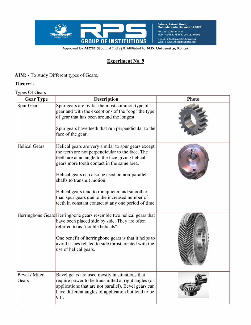
Spur Gears Spur gears are by far the most common type of
gear and with the exceptions of the "cog" the type
of gear that has been around the longest.
Spur gears have teeth that run perpendicular to the
face of the gear.
Helical Gears Helical gears are very similar to spur gears except
the teeth are not perpendicular to the face. The
teeth are at an angle to the face giving helical
gears more tooth contact in the same area.
Helical gears can also be used on non-parallel
shafts to transmit motion.
Helical gears tend to run quieter and smoother
than spur gears due to the increased number of
teeth in constant contact at any one period of time.
Herringbone Gears Herringbone gears resemble two helical gears that
have been placed side by side. They are often
referred to as "double helicals".
One benefit of herringbone gears is that it helps to
avoid issues related to side thrust created with the
use of helical gears.
Bevel / Miter
Gears
Bevel gears are used mostly in situations that
require power to be transmitted at right angles (or
applications that are not parallel). Bevel gears can
have different angles of application but tend to be
90°.

Worm Gears Worm gears are used to transmit power at 90° and
where high reductions are required. The worm
resembles a thread that rides in concaved or
helical teeth.
Internal Gears Internal gears typically resemble inverted spur
gears but are occasionally cut as helical gears.
Racks A rack is basically a straight gear used to transmit
power and motion in a linear movement.
Face Gears Face gears transmit power at (usually) right angles
in a circular motion. Face gears are not very
common in industrial application.
Involute Splines Splined shafts and hubs are usually used as
connectors in many different types of applications.
One of the most common applications is to
connect motors to gear reducers. They may also be
used in transmissions.
Involute splines resemble spur gears, but tend to
have different pressure angles.
Straight Sided
Splines
Straight sided splines often serve the same
function as involute splines but have "straight
sided" teeth instead of involute teeth.
Sprockets Sprockets are used to run chains or belts. They are
typically used in conveyor systems.
Experiment No. 10
AIM: - To study Different types of Gear Trains.
Theory: -
There are several types of gear trains. In some cases, the axes of rotation of the gears are fixed in space. In one
case, gears revolve about axes which are not fixed in space.
Therefore, the gear trains can be classified into the following three classes:
(a) Simple gear train,
(b) Compound gear train, and
(c) Epicyclic or Planetary gear train.
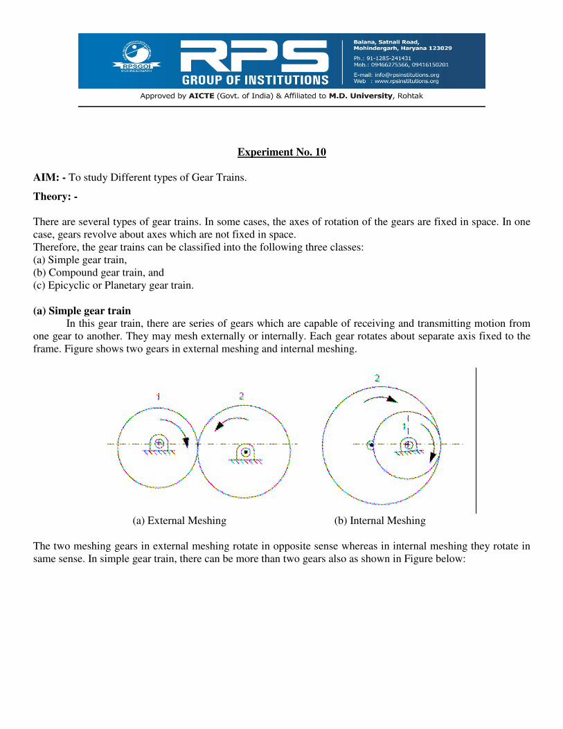
(a) Simple gear train
In this gear train, there are series of gears which are capable of receiving and transmitting motion from
one gear to another. They may mesh externally or internally. Each gear rotates about separate axis fixed to the
frame. Figure shows two gears in external meshing and internal meshing.
(a) External Meshing (b) Internal Meshing
The two meshing gears in external meshing rotate in opposite sense whereas in internal meshing they rotate in
same sense. In simple gear train, there can be more than two gears also as shown in Figure below:
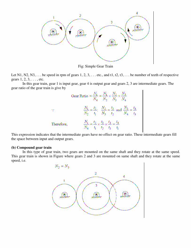
Fig: Simple Gear Train
Let N1, N2, N3, . . . be speed in rpm of gears 1, 2, 3, . . . etc., and t1, t2, t3, . . . be number of teeth of respective
gears 1, 2, 3, . . . , etc.
In this gear train, gear 1 is input gear, gear 4 is output gear and gears 2, 3 are intermediate gears. The
gear ratio of the gear train is give by
This expression indicates that the intermediate gears have no effect on gear ratio. These intermediate gears fill
the space between input and output gears.
(b) Compound gear train
In this type of gear train, two gears are mounted on the same shaft and they rotate at the same speed.
This gear train is shown in Figure where gears 2 and 3 are mounted on same shaft and they rotate at the same
speed, i.e.

(c) Epicyclic or Planetary gear train In an epicyclic gear train or planetary gear train, the axis of at least one of the gears also moves relative
to the frame. Figure shows an epicyclic gear train. It consists of two gears S and P. The axes of these gears are
connected with each other by an arm a. If arm is fixed, these two gears constitute a simple gear train. If gear S is
fixed and arm rotates about axis of gear S, it constitute an epicyclic gear train. It is, however, not necessary that
S is fixed; it may have some known rotational speed. Since gear P moves around gear S like a planet moving
around sun, it is also called planetary gear and gear S is called sun gear.
As the arm rotates, planetary gear P moves around gear S. Epicyclic gear trains are used in automotive
transmission, computing devices, vehicle differential, etc. An epicyclic gear train can be designed to provide
large gear ratio, also which is not possible in other gear trains in smaller space.


![Neutron scattering - Uppsala UniversityBasics of Neutron Scattering Experiments Kinematics of inelastically scattered neutrons : ħω [meV] ħ Q [Å-1] energy gain energy loss Ei =](https://static.fdocuments.in/doc/165x107/5fa1d6642e96c531a97c72dd/neutron-scattering-uppsala-basics-of-neutron-scattering-experiments-kinematics.jpg)