MDPE PE 2708 Natural Gas Distribution Documents for Submittals
5
NORTHERN CALIFORNIA 511 Tunnel Avenue Brisbane, CA 94005 415.467.4630 PFDistributors.com NEVADA 675-B Edison Way Reno, NV 89502 775.856.1888 SOUTHERN CALIFORNIA 1304 E. San Bernardino Ave San Bernardino, CA 92408 909.799.7800 Technical Data Sheet – Page 3 Typical material data values of MDPE resin and pipe for natural gas distribution applications Product Flyer – Page 2 Product description with key benefit highlights for natural gas distribution applications Pipe Size Chart – Page 4 MDPE size and pressure chart for various Standard Dimensional Ratio (SDR) MDPE PE 2708 Natural Gas Distribution Documents for Submittals This publication is intended for use as a piping system guide and shall not be used in place of a professional engineer’s judgment or guidance. The information in this publication does not constitute a guarantee or warranty for piping installations and cannot be guaranteed because the conditions of use are beyond individual controls. The user of this information assumes all risk associated with its use. P&F Distributors has made every reasonable effort to ensure accuracy, but the information in this publication may not be complete, especially for special or unusual applications. Changes to this publication may occur from time to time without notice. Please contact P&F Distributors to determine if you have the most current edition. CENTRAL CALIFORNIA 4039-C Well Tech Way Bakersfield, CA 93308 661.589.7300 Temperature Compensation Chart – Page 5 Temperature vs Dimensional Ratio chart based on pipe application and burial classification
Transcript of MDPE PE 2708 Natural Gas Distribution Documents for Submittals

NORTHERN CALIFORNIA 511 Tunnel Avenue Brisbane, CA 94005 415.467.4630 PFDistributors.com
NEVADA 675-B Edison Way Reno, NV 89502 775.856.1888
SOUTHERN CALIFORNIA 1304 E. San Bernardino Ave San Bernardino, CA 92408 909.799.7800
Technical Data Sheet – Page 3
Typical material data values of MDPE resin and pipe for natural gas distribution applications
Product Flyer – Page 2
Product description with key benefit highlights for natural gas distribution applications
Pipe Size Chart – Page 4
MDPE size and pressure chart for various Standard Dimensional Ratio (SDR)
MDPE PE 2708 Natural Gas Distribution
Documents for Submittals
This publication is intended for use as a piping system guide and shall not be used in place of a professional engineer’s judgment or guidance. The information in this publication does not constitute a guarantee or warranty for piping installations and cannot be guaranteed because the conditions of use are beyond individual controls. The user of this information assumes all risk associated with its use. P&F Distributors has made every reasonable effort to ensure accuracy, but the information in this publication may not be complete, especially for special or unusual applications. Changes to this publication may occur from time to time without notice. Please contact P&F Distributors to determine if you have the most current edition.
CENTRAL CALIFORNIA 4039-C Well Tech Way Bakersfield, CA 93308 661.589.7300
Temperature Compensation Chart – Page 5
Temperature vs Dimensional Ratio chart based on pipe application and burial classification

NORTHERN CALIFORNIA 511 Tunnel Avenue Brisbane, CA 94005 415.467.4630 PFDistributors.com
NEVADA 675-B Edison Way Reno, NV 89502 775.856.1888
SOUTHERN CALIFORNIA 1304 E. San Bernardino Ave San Bernardino, CA 92408 909.799.7800
Lowest Total Cost of Ownership
Lowest life cycle cost of any piping material when accounting for all costs: direct, indirect and operational costs
50+ Year Rated – Same Pipe New and Old
Hydrostatic design basis is established per ASTM D2837 to provide high confidence interval of lifetime material performance
Installation Flexibility – So Many Choices
Durable, lightweight and flexible paves way for trench and trenchless installation methods whether above, below grade or under rivers, lakes and obstacles
Consistent Pipe Joint Solution
Fusion joints are leak-free, fully restrained, homogenious, and repeatable through the innovative butt, socket, saddle and electrofusion joining methodology of ASTM F2620 and ASTM F1290 – When equipped with a Data Logging Device, joint information become fully transparent and worry-free
CENTRAL CALIFORNIA 4039-C Well Tech Way Bakersfield, CA 93308 661.589.7300
Tracking and Traceability
MDPE Pipe are marked per ASTM D2513 and adhere to DOT 49 CFR Part 192 regulations for plastic pipe tracking and traceability via a 16 digit scannable character code generated per ASTM F2897
Seismic Resistant Pipe
PE material’s high strain allowance combined with the lowest force generation provides a critial lifeline and complete piping solution to seismically active regions
MDPE Pipe for Regulated Natural Gas, LPG and Propane Applications
Please Contac t fo r Add i t iona l Techn ica l In fo rmat ion o r Ta i lo red Presen ta t ion

MDPE PE 2708 Technical Data Chart
Nominal MDPE Pipe
Property1ASTM Test
MethodUnit
Required by ASTM
D2513 for PE2708Typical Value
Cell Classification D3350 ‐ PE 234373E PE 234373E
Density w/ Min 2% Carbon
BlackD1505 g/cm3 > 0.925 ‐ 0.940 0.939
Melt Flow Index (190/2.16) D1238 g/10 min < 0.40 ‐ 0.15 0.18
Hydrostatic Design Basis
(HDB) @ 73°F (23°C)D2837 psi 1,600 1,250
Hydrostatic Design Stress
(HDB) @ 140°F (60°C)D2837 psi 1,000 800
Color: UV Stabilizer [E] D3350 ‐ ‐ Yellow
Nominal MDPE Material
Property2ASTM Test
MethodUnit
Required by ASTM
D2513 for PE2708Typical Value
Tensile Strength at Yield D638 psi 2,600 ‐ < 3,000 2,800
Tensile Elongation at Break D638 % ‐ 800
Slow Crack Growth (PENT) F1473 hrs > 500 > 2,000
Flexural Modulus D790 psi 80,000 ‐ < 110,000 > 90,000
Modulus of Elasticity (Short
Term3)D638 psi ‐ 100,000
Vicant Temperature D1525 °F ‐ 227
Brittleness Temperature D746 °F ‐ < ‐103
Hardness D2240 ‐ ‐ 63
Coefficient of Thermal
Expansion/ContractionD696 in/in ∙°F ‐ 10.0 x 10‐5
Compressive Stress ‐ psi ‐ 800
Thermal Conductivity ‐ BTU ∙in /hr ∙sq. ft ∙°F ‐ 2.6
Poisson's Ratio ‐ ‐ ‐ 0.451The nominal pipe properties were determined on pipe extruded from a pellet blend of typical resin and an approved color concentrate. 2The nominal properties
reported are typical of the resin when blended with an approved color concentrate, except the density value which is representative of the natural resin, but do
not reflect normal testing variance and therefore should not be used for specification purposes. Values are rounded. 3Ratio of stress to strain that that is
achieved at a certain defined strain. This apparent modulus is considered "short term" and is of limited value for engineering design.

Gas Distribution Sizing Chart ‐ MDPE
Pipe Size Actual OD Min. Wall Avg. ID Weight Min. Wall Avg. ID Weight Min. Wall Avg. ID Weight Min. Wall Avg. ID Weight
in. in. in. in. lb/ft in. in. lb/ft in. in. lb/ft in. in. lb/ft
1/2 0.84 0.090 0.649 0.09 0.076 0.678 0.08 0.073 0.685 0.08 0.062 0.708 0.07
3/4 1.05 0.113 0.811 0.14 0.095 0.848 0.12 0.091 0.856 0.12 0.078 0.885 0.10
1 1.315 0.141 1.016 0.22 0.120 1.062 0.19 0.114 1.073 0.19 0.097 1.108 0.16
1 1/4 1.66 0.178 1.283 0.35 0.151 1.340 0.31 0.144 1.354 0.29 0.123 1.399 0.25
1 1/2 1.90 0.204 1.468 0.46 0.173 1.534 0.40 0.165 1.550 0.39 0.141 1.602 0.33
2 2.375 0.255 1.835 0.73 0.216 1.917 0.63 0.207 1.937 0.60 0.176 2.002 0.52
3 3.50 0.375 2.705 1.58 0.318 2.825 1.36 0.304 2.855 1.31 0.259 2.950 1.13
4 4.50 0.482 3.477 2.61 0.409 3.633 2.26 0.391 3.670 2.17 0.333 3.793 1.87
6 6.63 0.711 5.124 5.66 0.603 5.352 4.90 0.577 5.408 4.70 0.491 5.589 4.07
8 8.63 0.925 6.669 9.59 0.785 6.967 8.29 0.750 7.039 7.97 0.639 7.275 6.89
10 10.75 1.152 8.307 14.88 0.977 8.678 12.87 0.935 8.768 12.37 0.796 9.062 10.69
12 12.75 1.367 9.853 20.94 1.159 10.293 18.10 1.109 10.400 17.40 0.944 10.748 15.04
Pipe Size Actual OD Min. Wall Avg. ID Weight Min. Wall Avg. ID Weight Min. Wall Avg. ID Weight Min. Wall Avg. ID Weight
in. in. in. in. lb/ft in. in. lb/ft in. in. lb/ft in. in. lb/ft
2 2.375 0.339 1.656 0.93
3 3.50 0.500 2.440 2.01 0.389 2.676 1.63
4 4.50 0.643 3.137 3.33 0.500 3.440 2.69 0.450 3.546 2.45 0.290 3.885 1.65
6 6.63 0.947 4.622 7.22 0.737 5.068 5.84 0.663 5.224 5.33 0.428 5.723 3.58
8 8.63 1.233 6.016 12.24 0.959 6.597 9.90 0.863 6.800 9.03 0.557 7.450 6.07
10 10.75 1.194 8.218 15.36 1.075 8.471 14.01 0.694 9.280 9.42
12 12.75 1.275 10.047 19.70 0.823 11.006 13.25
Pressure Rating 125 psi 120 psi 110 psi 60 psi
Pipe sizing per ASTM D2513 . Pressure Class calculations based on 0.4 DF at 73F per DOT 49 CFR §192.121. Average ID is approximate. Weights calculated based on PPI TR‐7.
Pipe sizing per ASTM D2513 . Pressure Class calculations based on 0.4 DF at 73F per DOT 49 CFR §192.121. Average ID is approximate. Weights calculated based on PPI TR‐7.
MDPE ‐ IPS Sizing DR 7 DR 9 DR 10 DR 15.5
MDPE ‐ IPS Sizing DR 9.33 DR 11 DR 11.5 DR 13.5
Pressure Rating 120 psi 100 psi 95 psi 80 psi
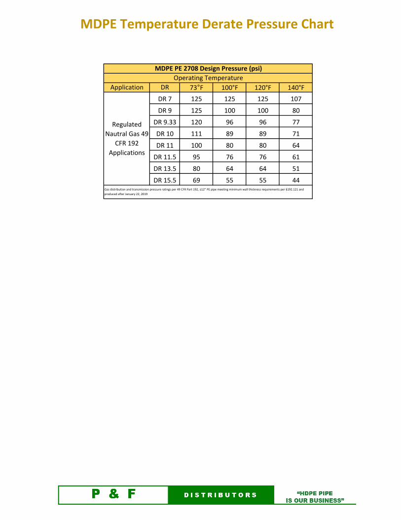
MDPE Temperature Derate Pressure Chart
Application DR 73°F 100°F 120°F 140°F
DR 7 125 125 125 107
DR 9 125 100 100 80
DR 9.33 120 96 96 77
DR 10 111 89 89 71
DR 11 100 80 80 64
DR 11.5 95 76 76 61
DR 13.5 80 64 64 51
DR 15.5 69 55 55 44
MDPE PE 2708 Design Pressure (psi)
Operating Temperature
Regulated
Nautral Gas 49
CFR 192
Applications
Gas distribution and transmission pressure ratings per 49 CFR Part 192, ≤12” PE pipe meeting minimum wall thickness requirements per §192.121 and
produced after January 22, 2019