MCS3142 Dual KeeLoq Encoder Wireless Remote Control...
57
2014 Microchip Technology Inc. DS40001746A MCS3142 Dual KEELOQ ® Encoder Wireless Remote Control Development Kit User’s Guide
Transcript of MCS3142 Dual KeeLoq Encoder Wireless Remote Control...
2014 Microchip Technology Inc. DS40001746A
MCS3142 Dual KEELOQ® EncoderWireless Remote Control
Development KitUser’s Guide
DS40001746A-page 2 2014 Microchip Technology Inc.
Information contained in this publication regarding deviceapplications and the like is provided only for your convenienceand may be superseded by updates. It is your responsibility toensure that your application meets with your specifications.MICROCHIP MAKES NO REPRESENTATIONS ORWARRANTIES OF ANY KIND WHETHER EXPRESS ORIMPLIED, WRITTEN OR ORAL, STATUTORY OROTHERWISE, RELATED TO THE INFORMATION,INCLUDING BUT NOT LIMITED TO ITS CONDITION,QUALITY, PERFORMANCE, MERCHANTABILITY ORFITNESS FOR PURPOSE. Microchip disclaims all liabilityarising from this information and its use. Use of Microchipdevices in life support and/or safety applications is entirely atthe buyer’s risk, and the buyer agrees to defend, indemnify andhold harmless Microchip from any and all damages, claims,suits, or expenses resulting from such use. No licenses areconveyed, implicitly or otherwise, under any Microchipintellectual property rights.
Note the following details of the code protection feature on Microchip devices:• Microchip products meet the specification contained in their particular Microchip Data Sheet.
• Microchip believes that its family of products is one of the most secure families of its kind on the market today, when used in the intended manner and under normal conditions.
• There are dishonest and possibly illegal methods used to breach the code protection feature. All of these methods, to our knowledge, require using the Microchip products in a manner outside the operating specifications contained in Microchip’s Data Sheets. Most likely, the person doing so is engaged in theft of intellectual property.
• Microchip is willing to work with the customer who is concerned about the integrity of their code.
• Neither Microchip nor any other semiconductor manufacturer can guarantee the security of their code. Code protection does not mean that we are guaranteeing the product as “unbreakable.”
Code protection is constantly evolving. We at Microchip are committed to continuously improving the code protection features of ourproducts. Attempts to break Microchip’s code protection feature may be a violation of the Digital Millennium Copyright Act. If such actsallow unauthorized access to your software or other copyrighted work, you may have a right to sue for relief under that Act.
Microchip received ISO/TS-16949:2009 certification for its worldwide headquarters, design and wafer fabrication facilities in Chandler and Tempe, Arizona; Gresham, Oregon and design centers in California and India. The Company’s quality system processes and procedures are for its PIC® MCUs and dsPIC® DSCs, KEELOQ® code hopping devices, Serial EEPROMs, microperipherals, nonvolatile memory and analog products. In addition, Microchip’s quality system for the design and manufacture of development systems is ISO 9001:2000 certified.
QUALITY MANAGEMENT SYSTEM CERTIFIED BY DNV
== ISO/TS 16949 ==
Trademarks
The Microchip name and logo, the Microchip logo, dsPIC, FlashFlex, KEELOQ, KEELOQ logo, MPLAB, PIC, PICmicro, PICSTART, PIC32 logo, rfPIC, SST, SST Logo, SuperFlash and UNI/O are registered trademarks of Microchip Technology Incorporated in the U.S.A. and other countries.
FilterLab, Hampshire, HI-TECH C, Linear Active Thermistor, MTP, SEEVAL and The Embedded Control Solutions Company are registered trademarks of Microchip Technology Incorporated in the U.S.A.
Silicon Storage Technology is a registered trademark of Microchip Technology Inc. in other countries.
Analog-for-the-Digital Age, Application Maestro, BodyCom, chipKIT, chipKIT logo, CodeGuard, dsPICDEM, dsPICDEM.net, dsPICworks, dsSPEAK, ECAN, ECONOMONITOR, FanSense, HI-TIDE, In-Circuit Serial Programming, ICSP, Mindi, MiWi, MPASM, MPF, MPLAB Certified logo, MPLIB, MPLINK, mTouch, Omniscient Code Generation, PICC, PICC-18, PICDEM, PICDEM.net, PICkit, PICtail, REAL ICE, rfLAB, Select Mode, SQI, Serial Quad I/O, Total Endurance, TSHARC, UniWinDriver, WiperLock, ZENA and Z-Scale are trademarks of Microchip Technology Incorporated in the U.S.A. and other countries.
SQTP is a service mark of Microchip Technology Incorporated in the U.S.A.
GestIC and ULPP are registered trademarks of Microchip Technology Germany II GmbH & Co. KG, a subsidiary of Microchip Technology Inc., in other countries.
All other trademarks mentioned herein are property of their respective companies.
© 2014, Microchip Technology Incorporated, Printed in the U.S.A., All Rights Reserved.
Printed on recycled paper.
ISBN: 9781620779422
DS40001746A-page 3 2014 Microchip Technology Inc.
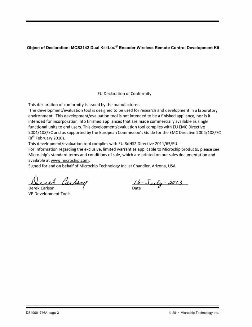
Object of Declaration: MCS3142 Dual KEELOQ® Encoder Wireless Remote Control Development Kit
MCS3142 DUAL KEELOQ® ENCODERWIRELESS REMOTE CONTROL
DEVELOPMENT KIT USER’S GUIDE
Table of Contents
Preface ........................................................................................................................... 5Introduction............................................................................................................ 5Document Layout .................................................................................................. 5Conventions Used in this Guide ............................................................................ 6Recommended Reading........................................................................................ 7The Microchip Web Site ........................................................................................ 7Customer Support ................................................................................................. 8Document Revision History ................................................................................... 8
Chapter 1. Overview1.1 Introduction ..................................................................................................... 91.2 Kit Contents .................................................................................................... 9
1.2.1 Downloadable Content ................................................................................ 9
Chapter 2. Quick Start2.1 Introduction ................................................................................................... 102.2 Using the Stand-alone Demo ....................................................................... 10
2.2.1 Setup ......................................................................................................... 102.2.2 Operation ................................................................................................... 12
2.3 KEELOQ Screens .......................................................................................... 13Chapter 3. Hardware Self-Test
3.1 Introduction ................................................................................................... 183.2 Button Tests ................................................................................................. 183.3 LED Tests ..................................................................................................... 183.4 RTCC Test ................................................................................................... 183.5 SPI Test ........................................................................................................ 19
Chapter 4. MCS3142 Wireless Remote Key Fob4.1 Introduction ................................................................................................... 20
Chapter 5. Embedded Security Development Board5.1 Introduction ................................................................................................... 215.2 Serial Communications Connections ........................................................... 225.3 Serial Accessory Port (P20) ......................................................................... 225.4 USB Interface Port ....................................................................................... 235.5 PICtail™ Port ................................................................................................ 235.6 LCD Display ................................................................................................. 235.7 Real-Time Clock and Calendar (RTCC) Module .......................................... 235.8 Push Buttons ................................................................................................ 245.9 LEDs ............................................................................................................. 24
2014 Microchip Technology Inc. DS40001746A-page 3
MCS3142 Dual KEELOQ® Encoder Wireless Remote Control Development Kit User’s Guide
5.10 Power Supply ............................................................................................. 245.11 ICSP™ Programming/Debugging Ports ..................................................... 255.12 SX1239 Receiver PICtail Daughter Board ................................................. 25
Chapter 6. Developing with the MCS3142 Wireless Security Remote Control Development Kit
6.1 Introduction ................................................................................................... 276.2 Programming the MCS3142 ......................................................................... 276.3 Developing with the Embedded Security Board ........................................... 27
6.3.1 Software Design .........................................................................................28
Chapter 7. KEELOQ® MPLAB® X Plugin7.1 Introduction ................................................................................................... 307.2 Install ............................................................................................................ 307.3 Export SQTP ................................................................................................ 32
7.3.1 SQTP File Generation ................................................................................327.3.2 File format ..................................................................................................337.3.3 Generate Source ........................................................................................34
Chapter 8. PC Application8.1 Introduction ................................................................................................... 35
8.1.1 PC Application Features ............................................................................358.1.2 PC Requirements .......................................................................................35
8.2 Installation .................................................................................................... 358.2.1 Installing the Wireless Security Remote Kit GUI ........................................358.2.2 Installing the MCP2200 USB Driver ...........................................................35
8.3 PC Quick-Start ............................................................................................. 368.3.1 Connecting to the board .............................................................................368.3.2 Viewing Data ..............................................................................................38
8.4 Pairing a transmitter ..................................................................................... 388.5 Normal Operation ......................................................................................... 39
8.5.1 KEELOQ Graphic Specifics .........................................................................40
8.6 Calculator ..................................................................................................... 428.7 Receiver Settings ......................................................................................... 438.8 Versioning .................................................................................................... 43
Appendix A. MCS3142 Transmitter Fob Schematic Appendix B. SX1239 Receiver PICtail™ Daughter Board Schematics Appendix C. Embedded Security Development Board Schematics Worldwide Sales and Service .....................................................................................56
DS40001746A-page 4 2014 Microchip Technology Inc.

MCS3142 DUAL KEELOQ® ENCODERWIRELESS REMOTE CONTROL
DEVELOPMENT KIT USER’S GUIDE
Preface
INTRODUCTIONThis chapter contains general information that will be useful to know before using the MCS3142 Dual KEELOQ® Encoder Wireless Remote Control Development Kit. Items discussed in this chapter include:• Document Layout• Conventions Used in this Guide• Recommended Reading• The Microchip Web Site• Customer Support• Document Revision History
DOCUMENT LAYOUTThis document describes how to use the MCS3142 Dual KEELOQ Encoder Wireless Remote Control Development Kit as a development tool to emulate and debug firmware on a target board. The manual layout is as follows:• Chapter 1. “Overview”• Chapter 2. “Quick Start”• Chapter 3. “Hardware Self-Test”• Chapter 4. “MCS3142 Wireless Remote Key Fob”• Chapter 5. “Embedded Security Development Board”• Chapter 6. “Developing with the MCS3142 Wireless Security Remote Control
Development Kit”• Chapter 7. “KEELOQ MPLAB X Plugin”• Chapter 8. “PC Application”• Appendix A. “MCS3142 Transmitter Fob Schematic”• Appendix B. “SX1239 Receiver PICtail™ Daughter Board Schematics”• Appendix C. “Embedded Security Development Board Schematics”
2014 Microchip Technology Inc. DS40001746A-page 5
MCS3142 Dual KEELOQ® Encoder Wireless Remote Control Development Kit User’s Guide
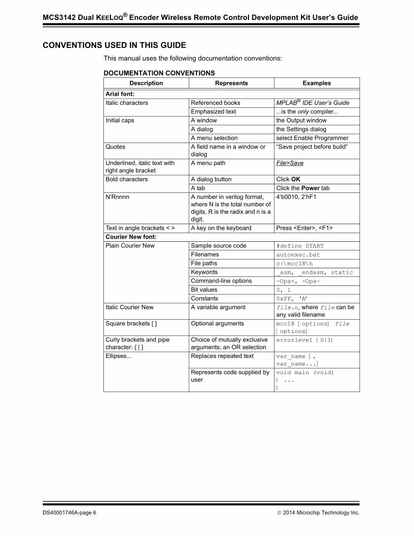
CONVENTIONS USED IN THIS GUIDEThis manual uses the following documentation conventions:
DOCUMENTATION CONVENTIONSDescription Represents Examples
Arial font:Italic characters Referenced books MPLAB® IDE User’s Guide
Emphasized text ...is the only compiler...Initial caps A window the Output window
A dialog the Settings dialogA menu selection select Enable Programmer
Quotes A field name in a window or dialog
“Save project before build”
Underlined, italic text with right angle bracket
A menu path File>Save
Bold characters A dialog button Click OKA tab Click the Power tab
N‘Rnnnn A number in verilog format, where N is the total number of digits, R is the radix and n is a digit.
4‘b0010, 2‘hF1
Text in angle brackets < > A key on the keyboard Press <Enter>, <F1>Courier New font:Plain Courier New Sample source code #define START
Filenames autoexec.bat
File paths c:\mcc18\h
Keywords _asm, _endasm, static
Command-line options -Opa+, -Opa-
Bit values 0, 1
Constants 0xFF, ‘A’
Italic Courier New A variable argument file.o, where file can be any valid filename
Square brackets [ ] Optional arguments mcc18 [options] file [options]
Curly brackets and pipe character: { | }
Choice of mutually exclusive arguments; an OR selection
errorlevel {0|1}
Ellipses... Replaces repeated text var_name [, var_name...]
Represents code supplied by user
void main (void){ ...}
DS40001746A-page 6 2014 Microchip Technology Inc.

Preface
RECOMMENDED READINGThis user’s guide describes how to use the MCS3142 Dual KEELOQ Encoder Wireless Remote Control Development Kit. Other useful documents are listed below. The following Microchip documents are available and recommended as supplemental reference resources.Read me FilesFor the latest information on using other tools, read the tool-specific Readme files in the Readmes subdirectory of the MPLAB X® IDE installation directory. The Readme files contain update information and known issues that may not be included in this user’s guide.Design CenterMicrochip has a KEELOQ design center which can be found on www.microchip.com/keeloq.
THE MICROCHIP WEB SITEMicrochip provides online support via our web site at www.microchip.com. This web site is used as a means to make files and information easily available to customers. Accessible by using your favorite Internet browser, the web site contains the following information:• Product Support – Data sheets and errata, application notes and sample
programs, design resources, user’s guides and hardware support documents, latest software releases and archived software
• General Technical Support – Frequently Asked Questions (FAQs), technical support requests, online discussion groups, Microchip consultant program member listing
• Business of Microchip – Product selector and ordering guides, latest Microchip press releases, listing of seminars and events, listings of Microchip sales offices, distributors and factory representatives
2014 Microchip Technology Inc. DS40001746A-page 7

MCS3142 Dual KEELOQ® Encoder Wireless Remote Control Development Kit User’s Guide
CUSTOMER SUPPORTUsers of Microchip products can receive assistance through several channels:• Distributor or Representative• Local Sales Office• Field Application Engineer (FAE)• Technical SupportCustomers should contact their distributor, representative or field application engineer (FAE) for support. Local sales offices are also available to help customers. A listing of sales offices and locations is included in the back of this document.Technical support is available through the web site at: http://support.microchip.com
DOCUMENT REVISION HISTORY
Revision A (February 2014)• Initial Release of this Document.
DS40001746A-page 8 2014 Microchip Technology Inc.
MCS3142 DUAL KEELOQ® ENCODERWIRELESS REMOTE CONTROL
DEVELOPMENT KIT USER’S GUIDE
Chapter 1. Overview
1.1 INTRODUCTIONThis document details how to use the stand-alone MCS3142 development kit, as well as the associated PC application and the MPLAB X plugin. The addition of a PC application allows much greater flexibility in accessing and viewing the captured wireless data. The MPLAB X plugin provides programming support for the MCS3142 as well as for the other KEELOQ devices.The MCS3142 Dual KEELOQ Encoder Wireless Remote Kit contains a receiver platform and MCS3142 transmitter that are used in conjunction with each other to showcase the various technologies of KEELOQ: Classic KEELOQ and Ultimate KEELOQ. For details on Classic KEELOQ and Ultimate KEELOQ, please refer to Microchip application notes AN1259, “KEELOQ® Microcontroller-Based Code Hopping Encoder”.
1.2 KIT CONTENTS• Embedded Security Development Board• MCS3142 Wireless Remote Key Fob• SX1239 Receiver PICtail™ Daughter Board• USB A to Mini-B Cable• CR2032 Coin Cell Battery
1.2.1 Downloadable ContentThe following latest software builds should be obtained from the Microchip web site:• Embedded Security Development Board source code• MPLAB X Integrated Development Environment
- KEELOQ Plugin (see Chapter 7. “KEELOQ MPLAB X Plugin”)• KEELOQ Graphical Interface for the Embedded Security Development Board
2014 Microchip Technology Inc. DS40001746A-page 9
MCS3142 DUAL KEELOQ® ENCODERWIRELESS REMOTE CONTROL
DEVELOPMENT KIT USER’S GUIDE
Chapter 2. Quick Start
2.1 INTRODUCTIONThe MCS3142 Dual KEELOQ Encoder Wireless Remote Control Development Kit uses an identical receiver module and demo board as seen in the Wireless Security Remote Control Development Kit User’s Guide. (http://ww1.microchip.com/downloads/en/DeviceDoc/41646A.pdf). This chapter will explain how to setup the board and show the general operation.
2.2 USING THE STAND-ALONE DEMO
2.2.1 SetupThere are only a few steps to perform to get the stand-alone demo working:1. Open the plastic enclosure of the red key fob by carefully prying apart the two
halves with a flat-head screw driver. Observe the correct battery polarity and insert the coin battery into the holder. Put the key fob back together.
2. To verify that the key fob is properly installed, press any button and the LED should flash when a button is pressed.
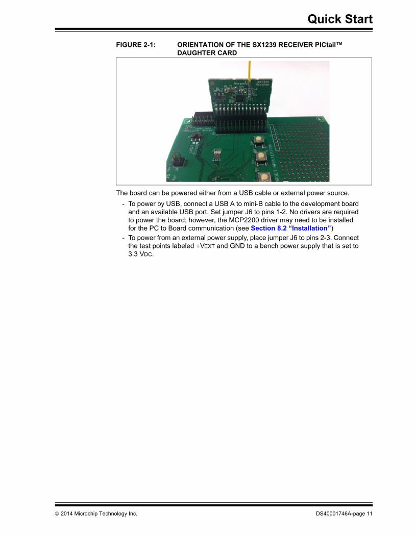
3. Plug in the RF receiver daughter board on the PICtail slot of the demo board. Make sure that the RF receiver daughter board has the side with the RF receiver chip facing the center, as shown in Figure 2-1.
2014 Microchip Technology Inc. DS40001746A-page 10
Quick Start
FIGURE 2-1: ORIENTATION OF THE SX1239 RECEIVER PICtail™ DAUGHTER CARD
The board can be powered either from a USB cable or external power source. - To power by USB, connect a USB A to mini-B cable to the development board
and an available USB port. Set jumper J6 to pins 1-2. No drivers are required to power the board; however, the MCP2200 driver may need to be installed for the PC to Board communication (see Section 8.2 “Installation”)
- To power from an external power supply, place jumper J6 to pins 2-3. Connect the test points labeled +VEXT and GND to a bench power supply that is set to 3.3 VDC.
2014 Microchip Technology Inc. DS40001746A-page 11
MCS3142 Dual KEELOQ® Encoder Wireless Remote
2.2.2 OperationThe pre-programmed demo is used to demonstrate the operation of Microchip Remote Keyless Entry (RKE) solutions. The demo highlights the capabilities of transmitting and receiving secured data wirelessly. Two different methods, Classic KEELOQ and Ultimate KEELOQ, are used in this demo.The pre-programmed demonstration shows how to secure information during data transmission.The transmitter sends out two types of packets. A Typical packet contains the device serial number, button code, synchronization counter, timer (Ultimate KEELOQ only) and various other parameters used in the decryption and validation process. A Seed packet contains special data related to the encoder’s encryption key. A Seed packet is sent infrequently, and only used when pairing a transmitter to a receiver.
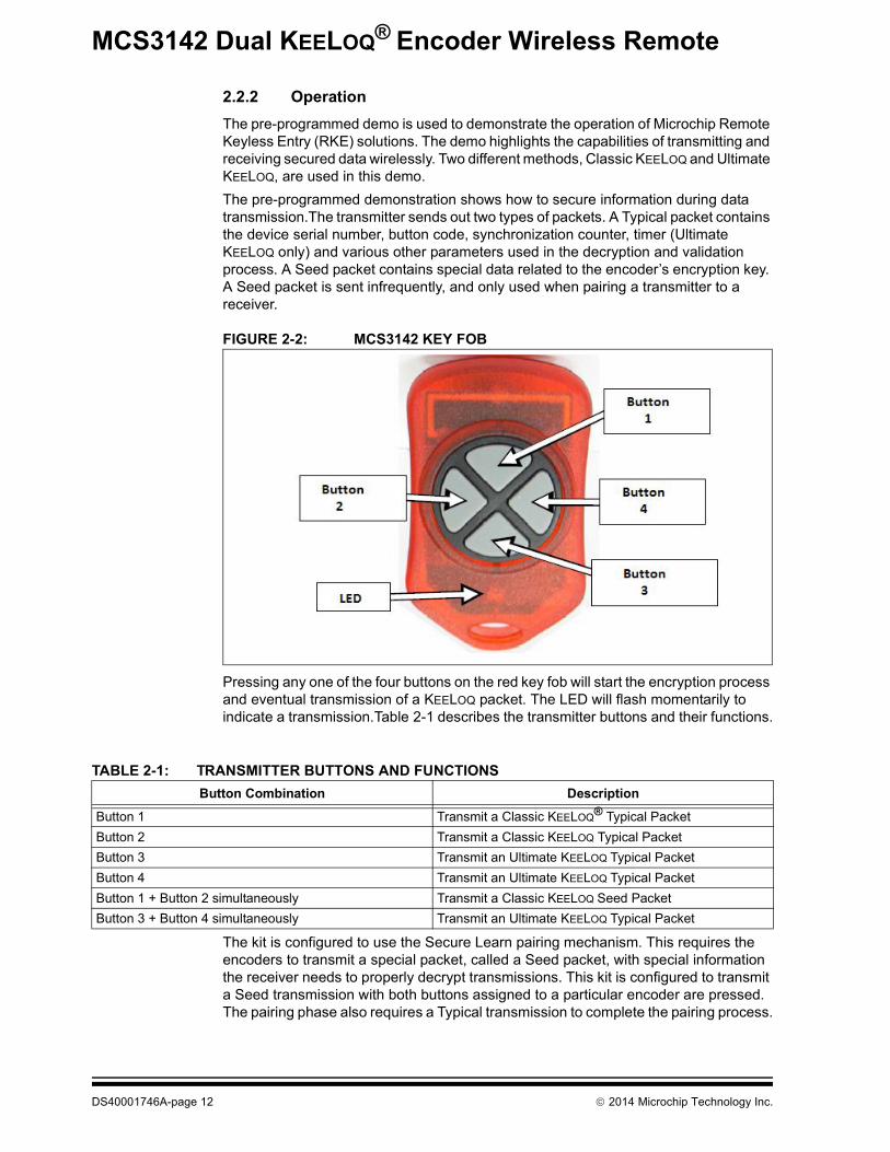
FIGURE 2-2: MCS3142 KEY FOB
Pressing any one of the four buttons on the red key fob will start the encryption process and eventual transmission of a KEELOQ packet. The LED will flash momentarily to indicate a transmission.Table 2-1 describes the transmitter buttons and their functions.
The kit is configured to use the Secure Learn pairing mechanism. This requires the encoders to transmit a special packet, called a Seed packet, with special information the receiver needs to properly decrypt transmissions. This kit is configured to transmit a Seed transmission with both buttons assigned to a particular encoder are pressed. The pairing phase also requires a Typical transmission to complete the pairing process.
TABLE 2-1: TRANSMITTER BUTTONS AND FUNCTIONSButton Combination Description
Button 1 Transmit a Classic KEELOQ® Typical PacketButton 2 Transmit a Classic KEELOQ Typical PacketButton 3 Transmit an Ultimate KEELOQ Typical PacketButton 4 Transmit an Ultimate KEELOQ Typical PacketButton 1 + Button 2 simultaneously Transmit a Classic KEELOQ Seed PacketButton 3 + Button 4 simultaneously Transmit an Ultimate KEELOQ Typical Packet
DS40001746A-page 12 2014 Microchip Technology Inc.
Quick Start
To pair a transmitter to the receiver using Secure learn:1. Press SW3, the Secure Learn button on the Embedded Security Development
Board to enable Secure Learn mode.2. If learning the Classic KEELOQ encoder, press both buttons 1 and 2. If learning
the Ultimate KEELOQ encoder, press both buttons 3 and 4. This will cause the special Seed packet to be sent.
3. The receiver will indicate reception of the Seed transmission.4. If learning the Ultimate KEELOQ encoder, press either button 3 or 4 to send a
Typical transmission.5. The receiver will indicate successful pairing.The kit also includes the SX1239 Receiver PICtail Daughter Board. It houses the Semtech SX1239 wideband receiver. The target application configured the receiver on start-up.
2.3 KEELOQ SCREENSThis section describes all of the LCD screens when used with the MCS3142 transmitter.
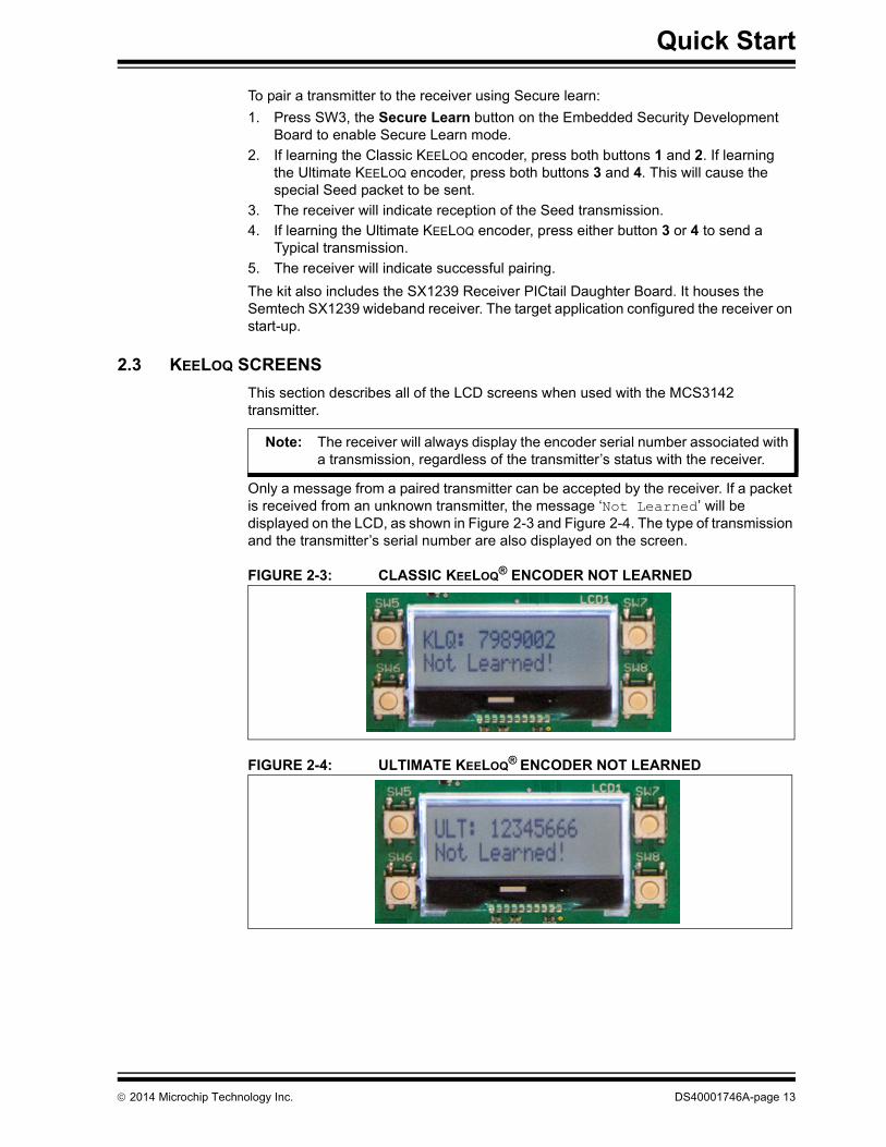
Only a message from a paired transmitter can be accepted by the receiver. If a packet is received from an unknown transmitter, the message ‘Not Learned’ will be displayed on the LCD, as shown in Figure 2-3 and Figure 2-4. The type of transmission and the transmitter’s serial number are also displayed on the screen.
FIGURE 2-3: CLASSIC KEELOQ® ENCODER NOT LEARNED
FIGURE 2-4: ULTIMATE KEELOQ® ENCODER NOT LEARNED
Note: The receiver will always display the encoder serial number associated with a transmission, regardless of the transmitter’s status with the receiver.
2014 Microchip Technology Inc. DS40001746A-page 13

MCS3142 Dual KEELOQ® Encoder Wireless Remote
When a Classic KEELOQ packet is received from a paired transmitter, the contents of the packet is displayed on the LCD, as shown in Figure 2-5. Table 2-2 describes the data displayed on the screen.
FIGURE 2-5: TYPICAL CLASSIC KEELOQ® TRANSMISSION
When a Classic KEELOQ packet is received from a paired transmitter, the contents of the packet is displayed on the LCD, as shown in Figure 2-6. Table 2-3 describes the data displayed on the screen.
FIGURE 2-6: TYPICAL ULTIMATE KEELOQ® TRANSMISSION
TABLE 2-2: CLASSIC KEELOQ® TYPICAL TRANSMISSION DATA‘KLQ’ Indicates a Classic KEELOQ® encoder‘7989002’ The encoder’s serial number‘C: 1008’ The encoder’s synchronization counter value‘F: 2’ The encoder’s function code
TABLE 2-3: ULTIMATE KEELOQ® TYPICAL TRANSMISSION DATA‘ULT’ Indicates an Ultimate KEELOQ® encoder‘12345666’ The encoder’s serial number‘T: 00330A1F’ The encoder’s time-stamp‘F: 04’ The encoder’s function code
DS40001746A-page 14 2014 Microchip Technology Inc.
Quick Start
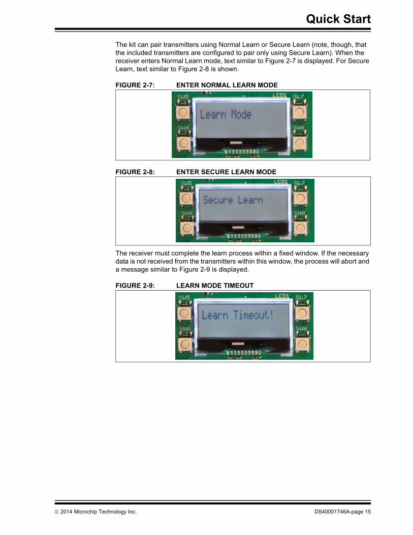
The kit can pair transmitters using Normal Learn or Secure Learn (note, though, that the included transmitters are configured to pair only using Secure Learn). When the receiver enters Normal Learn mode, text similar to Figure 2-7 is displayed. For Secure Learn, text similar to Figure 2-8 is shown.
FIGURE 2-7: ENTER NORMAL LEARN MODE
FIGURE 2-8: ENTER SECURE LEARN MODE
The receiver must complete the learn process within a fixed window. If the necessary data is not received from the transmitters within this window, the process will abort and a message similar to Figure 2-9 is displayed.
FIGURE 2-9: LEARN MODE TIMEOUT
2014 Microchip Technology Inc. DS40001746A-page 15
MCS3142 Dual KEELOQ® Encoder Wireless Remote
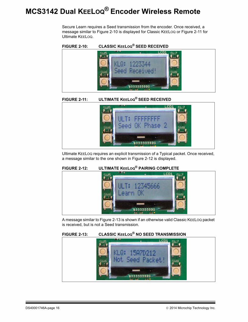
Secure Learn requires a Seed transmission from the encoder. Once received, a message similar to Figure 2-10 is displayed for Classic KEELOQ or Figure 2-11 for Ultimate KEELOQ.
FIGURE 2-10: CLASSIC KEELOQ® SEED RECEIVED
FIGURE 2-11: ULTIMATE KEELOQ® SEED RECEIVED
Ultimate KEELOQ requires an explicit transmission of a Typical packet. Once received, a message similar to the one shown in Figure 2-12 is displayed.
FIGURE 2-12: ULTIMATE KEELOQ® PAIRING COMPLETE
A message similar to Figure 2-13 is shown if an otherwise valid Classic KEELOQ packet is received, but is not a Seed transmission.
FIGURE 2-13: CLASSIC KEELOQ® NO SEED TRANSMISSION
DS40001746A-page 16 2014 Microchip Technology Inc.
Quick Start
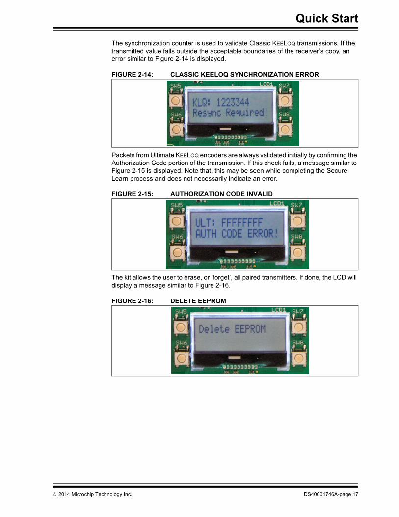
The synchronization counter is used to validate Classic KEELOQ transmissions. If the transmitted value falls outside the acceptable boundaries of the receiver’s copy, an error similar to Figure 2-14 is displayed.
FIGURE 2-14: CLASSIC KEELOQ SYNCHRONIZATION ERROR
Packets from Ultimate KEELOQ encoders are always validated initially by confirming the Authorization Code portion of the transmission. If this check fails, a message similar to Figure 2-15 is displayed. Note that, this may be seen while completing the Secure Learn process and does not necessarily indicate an error.
FIGURE 2-15: AUTHORIZATION CODE INVALID
The kit allows the user to erase, or ‘forget’, all paired transmitters. If done, the LCD will display a message similar to Figure 2-16.
FIGURE 2-16: DELETE EEPROM
2014 Microchip Technology Inc. DS40001746A-page 17
MCS3142 DUAL KEELOQ® ENCODERWIRELESS REMOTE CONTROL
DEVELOPMENT KIT USER’S GUIDE
Chapter 3. Hardware Self-Test
3.1 INTRODUCTIONA hardware self-check can be performed to ensure the hardware integrity of the Embedded Security Development Board. The instruction of the hardware self-check is displayed on the LCD. The test result is either checked by firmware and displayed on the LCD, or verified by user observation.To initiate the hardware self-check, press and hold push button SW1 before powering-up the Embedded Security Development Board. SW1 can then be released when “HDW Self Tests” is displayed on the LCD screen.
3.2 BUTTON TESTS“Button Test” will be displayed on the first line of the LCD display. Test instructions of pressing individual buttons will be displayed on the second line of the LCD display. Once a required push button is pressed, the test instruction message will be changed for the next push button. Once all push buttons have been tested, SW1 needs to be pressed to move forward to the LED test.
3.3 LED TESTSThere are two sets of LEDs. When the LED tests start, the message “LEDs Flashing” will be displayed on the first line of the LCD display. During the tests, two sets four LEDs (D4-D7) and seven LEDs (D8-D14) will flash in a pattern. The user should observe that all LEDs are turned on and off with flashing intervals of roughly one second. Once the user has verified the LED test, SW1 needs to be pressed to move forward to the RTCC test.
3.4 RTCC TESTWhen RTCC tests are initiated, the LCD display will show the clock and calendar. If no coin battery for the RTCC has been installed, the time displayed will be close to the reset time of January the 1st, 2012. If a coin battery for RTCC is installed, the time displayed will be based on whatever was previously set, plus the time that has passed. Observe that the clock is advancing. Once the RTCC test is done, SW1 needs to be pressed to move forward to the SPI test.
2014 Microchip Technology Inc. DS40001746A-page 18
Hardware Self-Test
3.5 SPI TESTThe SPI test in hardware self-check is performed to the SPI bus that connects the target application microcontroller and the SX1239 Receiver PICtail Daughter Board. Therefore, the SX1239 Receiver PICtail Daughter Board must have been plugged in before this test starts. Once the SPI test starts, the target application microcontroller requests specific information from the SX1239 receiver through the SPI bus. If the expected response is received, then the “Successful” status will appear; otherwise, the “Fail” status will be displayed.
Note: If a PICtail daughter board, other than the SX1239 Receiver PICtail™ Daughter Board, is plugged into the PICtail connector (even though the SPI bus may still be working), the SPI test might show failure status. The demo board expects an SX1239 to be identified on the SPI interface.
2014 Microchip Technology Inc. DS40001746A-page 19
MCS3142 DUAL KEELOQ® ENCODERWIRELESS REMOTE CONTROL
DEVELOPMENT KIT USER’S GUIDE
Chapter 4. MCS3142 Wireless Remote Key Fob
4.1 INTRODUCTIONThe MCS3142 Wireless Remote Key Fob is a demonstration and development platform for wireless security remote control applications. Please see http://ww1.microchip.com/downloads/en/DeviceDoc/41646A.pdf for similar information about the transmitter printed circuit board and its antenna design.
2014 Microchip Technology Inc. DS40001746A-page 20

MCS3142 DUAL KEELOQ® ENCODERWIRELESS REMOTE CONTROL
DEVELOPMENT KIT USER’S GUIDE
Chapter 5. Embedded Security Development Board
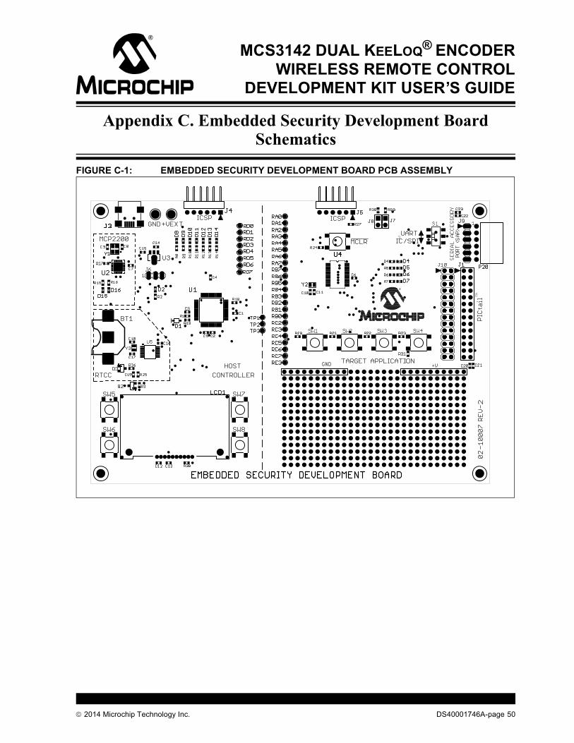
5.1 INTRODUCTIONThis section gives a detailed description of the development board. The layout can be seen in Figure 5-1.
FIGURE 5-1: EMBEDDED SECURITY DEVELOPMENT BOARD
The following main blocks are defined on the Embedded Security Development Board in Table 5-1:
TABLE 5-1: EMBEDDED SECURITY MODULE DEFINITIONS1 Target Application microcontroller U42 Host microcontroller U13 Serial Accessory Port P204 USB Interface Port J35 PICtail™ Connector J16 16x2 character LCD display7 Real-Time Clock and Calendar (RTCC) module U58 Push Buttons9 LEDs
10 Voltage Regulator11 ICSP™ Programming Ports, J4 for Host; J5 for Target Application
2014 Microchip Technology Inc. DS40001746A-page 21
MCS3142 Dual KEELOQ® Encoder Wireless Remote Control Development Kit User’s Guide
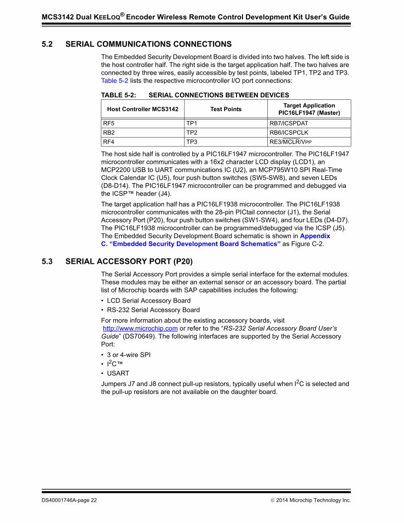
5.2 SERIAL COMMUNICATIONS CONNECTIONSThe Embedded Security Development Board is divided into two halves. The left side is the host controller half. The right side is the target application half. The two halves are connected by three wires, easily accessible by test points, labeled TP1, TP2 and TP3. Table 5-2 lists the respective microcontroller I/O port connections:
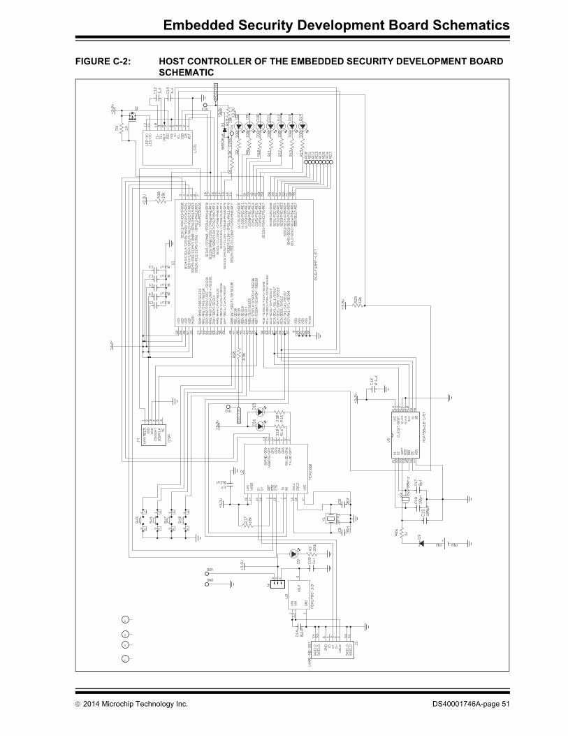
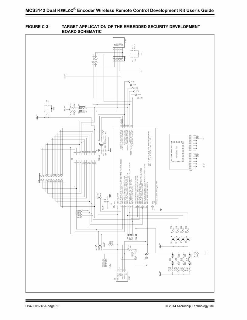
The host side half is controlled by a PIC16LF1947 microcontroller. The PIC16LF1947 microcontroller communicates with a 16x2 character LCD display (LCD1), an MCP2200 USB to UART communications IC (U2), an MCP795W10 SPI Real-Time Clock Calendar IC (U5), four push button switches (SW5-SW8), and seven LEDs (D8-D14). The PIC16LF1947 microcontroller can be programmed and debugged via the ICSP™ header (J4). The target application half has a PIC16LF1938 microcontroller. The PIC16LF1938 microcontroller communicates with the 28-pin PICtail connector (J1), the Serial Accessory Port (P20), four push button switches (SW1-SW4), and four LEDs (D4-D7). The PIC16LF1938 microcontroller can be programmed/debugged via the ICSP (J5). The Embedded Security Development Board schematic is shown in Appendix C. “Embedded Security Development Board Schematics” as Figure C-2.
5.3 SERIAL ACCESSORY PORT (P20)The Serial Accessory Port provides a simple serial interface for the external modules. These modules may be either an external sensor or an accessory board. The partial list of Microchip boards with SAP capabilities includes the following:• LCD Serial Accessory Board• RS-232 Serial Accessory BoardFor more information about the existing accessory boards, visit http://www.microchip.com or refer to the “RS-232 Serial Accessory Board User’s Guide” (DS70649). The following interfaces are supported by the Serial Accessory Port:• 3 or 4-wire SPI• I2C™• USARTJumpers J7 and J8 connect pull-up resistors, typically useful when I2C is selected and the pull-up resistors are not available on the daughter board.
TABLE 5-2: SERIAL CONNECTIONS BETWEEN DEVICES
Host Controller MCS3142 Test Points Target Application PIC16LF1947 (Master)
RF5 TP1 RB7/ICSPDATRB2 TP2 RB6/ICSPCLKRF4 TP3 RE3/MCLR/VPP
DS40001746A-page 22 2014 Microchip Technology Inc.
Embedded Security Development Board
5.4 USB INTERFACE PORTThe Microchip MCP2200 provides USB to UART support. The USB interface port can also be used to power the Embedded Security Development Board directly. Please see Section 8.2 “Installation” for more information about connecting the board to a PC.
5.5 PICtail™ PORTThe PICtail port is a 28-pin interface port that supports Microchip’s RF-based daughter cards. The PICtail port provides the following interfaces to the daughter cards:• Power Supply• SPI interface• Interrupt request lines• Other digital/analog I/O lines
There are many Microchip accessory daughter cards, which have PICtail port connectivity. When not used as one of the components in the Wireless Security Remote Control Development Kit, the Embedded Security Development Board can be connected with any daughter board with the PICtail port, and perform different functionalities. Refer to the Microchip web site http://www.microchip.com for accessory daughter boards with PICtail port.
5.6 LCD DISPLAYThe Embedded Security Development Board supports 16x2 character LCD display with backlight. The LCD is controlled by the host microcontroller through the SPI port.
5.7 REAL-TIME CLOCK AND CALENDAR (RTCC) MODULEThe Embedded Security Development Board RTCC module can be used to set and track clock and calendar precisely. The RTCC functionality is achieved with the Microchip MCP795W10. The RTCC module is controlled by the host microcontroller through the SPI interface. The RTCC is commonly used with Ultimate KEELOQ, which relies on the system clock as part of its security. The RTCC module can be powered either by the 3.3V power from the Embedded Security Development Board, or by a separate coin battery when external power is not available. For details on operating this RTCC module, refer to the data sheet of the MCP795W10 at http://www.microchip.com/MCP795W10.
Note: The user must be careful about the PICtail port pins that share different functions of the board. The user needs to check the schematics before assigning functions for any port pin.
2014 Microchip Technology Inc. DS40001746A-page 23

MCS3142 Dual KEELOQ® Encoder Wireless Remote Control Development Kit User’s Guide
5.8 PUSH BUTTONSThe Embedded Security Development Board has two sets of push buttons. SW1-SW4 on the target application side and SW5 on the host controller side.The four push buttons for the target application microcontroller are read as a single analog input. Depending on the different ratios of pull-up and pull-down resister values, the input analog voltages to the master microcontroller are different. Therefore, through the ADC on the target application microcontroller, the button that is pressed can be identified. Such design is used to save I/O pin requirement for the target application microcontroller.The four push buttons for the host microcontroller are four separate digital inputs to the slave microcontroller, due to the abundant I/O pin availability for the slave microcontroller. All buttons are assigned to the individual interrupt lines of the microcontroller and are not driven by external pull-up circuitry to save power consumption. The user software must enable the PORTB pull-ups of the microcontroller before evaluating the button state.The MCLR push button is connected to the RE3/MCLR pin of the target application microcontroller. The RE3/MCLR pin of the target application microcontroller is also one of the SPI lines that control the host microcontroller. When the target application and host microcontrollers are interconnected, the RE3/MCLR pin of target application microcontroller is configured to be a normal digital I/O pin; therefore, the MCLR push button is ineffective. Otherwise, if an I2C intercommunication is not required between the target application and host microcontroller, the pin can be configured as Reset and the MCLR button can be used.
5.9 LEDSThere are two sets of LEDs that are controlled by the target application and the host microcontrollers, respectively. The target application MCU controls a set of four LEDs through the digital output pins. The host MCU controls a set of six LEDs through digital output pins. The two sets of LEDs may be useful in the demo or debugging process.LEDs D15 and D16 on the left half are used to identify the TX and RX operation of MCP2200. The default configuration of the MCP2200 does not enable this feature, but it may be enabled using the MCP2200 configuration utility (see Section 7.2 “Install”). LEDs D12 and D13 are used by the preprogrammed demo firmware to identify the TX and RX communication between the host and target microcontrollers.LED D2 indicates the power availability. This LED cannot be controlled by the target application or by the host microcontroller.
5.10 POWER SUPPLYThe Embedded Security Development Board can be powered by one of the following two sources:• USB port• External 3.3V power source through GND and +VEXT connectorsJumper J6 is used to choose the power source. When the left side, pins 1-2 of J6 are closed, USB power is selected; when the right side, pins 2-3 of J6 are closed, external power source is selected.When the USB port is used to power the board, the input voltage is stabilized by a Microchip MCP1703, LDO regulator U3.
DS40001746A-page 24 2014 Microchip Technology Inc.

Embedded Security Development Board
5.11 ICSP™ PROGRAMMING/DEBUGGING PORTSThere are two ICSP™ programming/debugging ports on the Embedded Security Development Board. The ICSP port J4 on the left is used to program the host microcontroller. The ICSP port J5 on the right is used to program the target application microcontroller. Figure 5-2 shows the ICSP ports.
FIGURE 5-2: ICSP HEADERS FOR BOTH MICROS
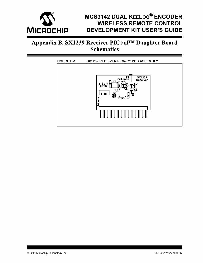
5.12 SX1239 RECEIVER PICtail DAUGHTER BOARDThe SX1239 PICtail Receiver Daughter Board is a demonstration and development platform for wireless security remote control applications. Figure 5-3 shows the SX1239 Receiver PICtail Daughter Board. The schematic, PCB layout, and Bill of Materials are listed in Appendix B. “SX1239 Receiver PICtail™ Daughter Board Schematics”.
FIGURE 5-3: SX129 PICtail™ DAUGHTER BOARD
2014 Microchip Technology Inc. DS40001746A-page 25

MCS3142 Dual KEELOQ® Encoder Wireless Remote Control Development Kit User’s Guide
The daughter board features the Semtech SX1239 Low-Power Integrated UHF Receiver (http://www.semtech.com/wireless-rf/rf-receivers/sx1239/). The PICtail daughter board can plug into the 28-pin PICtail connector, featured on many Microchip Technology development tools.The antenna connection has a pin socket for plugging a wire antenna. This demonstrates a simple and low-cost antenna option.The antenna pin socket can be removed by heating it with a soldering iron and cleaning the connection. An SMA or reverse polarity SMA (RP-SMA) connector can be soldered in place on the PCB. A whip or sleeve dipole antenna can then be used.If an SMA+ different antenna is used, the matching circuit will be less ideal. Pre-made antennas have a fixed, lower impedance. The wire used has a higher impedance.
DS40001746A-page 26 2014 Microchip Technology Inc.

MCS3142 DUAL KEELOQ® ENCODERWIRELESS REMOTE CONTROL
DEVELOPMENT KIT USER’S GUIDE
Chapter 6. Developing with the MCS3142 Wireless Security Remote Control Development Kit
6.1 INTRODUCTION
The software on the demo board was constructed so that a developer can easily customize the existing code base. The entire code is written in ‘C’ and has clearly documented sections where the developer can insert custom code.6.2 PROGRAMMING THE MCS3142Since the MCS3142 is a hardware encoder, its entire memory map cannot be programmed. Only portions of the MCS3142 memory are programmable. Please see Section 7.3.3 “Generate Source” for more information on how to generate code for the MCS3142 via the MPLAB X KEELOQ plugin. To modify the configuration data in the key fob, the developer needs to open the red plastic enclosure. The ICSP™ port is available on the key fob PCB as six contact areas. The following steps need to be followed to program the MCS3142:• Remove the PCB board from the plastic enclosure and lay the PCB board on a
non-conductive surface.• Align the six ICSP pins to the contact areas on the PCB. Push the ICSP pins to
the contact areas and avoid any movement during programming.
6.3 DEVELOPING WITH THE EMBEDDED SECURITY BOARDThe Embedded Security Development Board acts as a receiver in the MCS3142 Wireless Security Remote Control Development Kit. The target application microcontroller on the right side of the development board interacts with the receiver. All data receiving and KEELOQ security functionalities are performed by the target application microcontroller. The host microcontroller is only used to drive the LCD display and package data for the PC interface. The developer should only need to develop on the target side. The prototyping area under the four push buttons for target application controller can be used to prototype the application.
Note: Avoid touching the PCB antenna when testing.
2014 Microchip Technology Inc. DS40001746A-page 27
MCS3142 Dual KEELOQ® Encoder Wireless Remote Control Development Kit User’s Guide
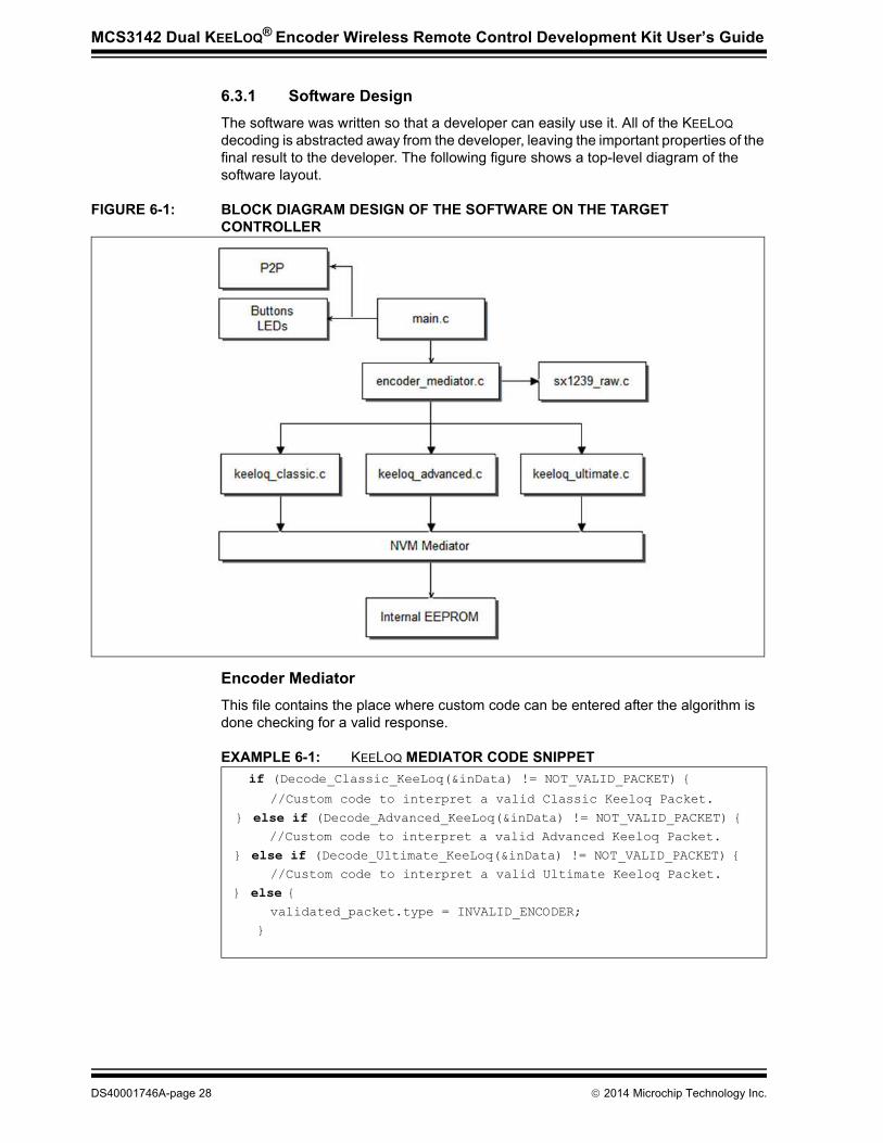
6.3.1 Software DesignThe software was written so that a developer can easily use it. All of the KEELOQ decoding is abstracted away from the developer, leaving the important properties of the final result to the developer. The following figure shows a top-level diagram of the software layout.
FIGURE 6-1: BLOCK DIAGRAM DESIGN OF THE SOFTWARE ON THE TARGET CONTROLLER
Encoder MediatorThis file contains the place where custom code can be entered after the algorithm is done checking for a valid response.
EXAMPLE 6-1: KEELOQ MEDIATOR CODE SNIPPET
if (Decode_Classic_KeeLoq(&inData) != NOT_VALID_PACKET) {
//Custom code to interpret a valid Classic Keeloq Packet.
} else if (Decode_Advanced_KeeLoq(&inData) != NOT_VALID_PACKET) {
//Custom code to interpret a valid Advanced Keeloq Packet.
} else if (Decode_Ultimate_KeeLoq(&inData) != NOT_VALID_PACKET) {
//Custom code to interpret a valid Ultimate Keeloq Packet.
} else {
validated_packet.type = INVALID_ENCODER;
}
DS40001746A-page 28 2014 Microchip Technology Inc.

Developing with the MCS3142 Wireless Security Remote Control Development Kit
Intra-Board CommunicationThis file contains the necessary communications between the two sides. The PC appli-cation needs to be informed of any updates relating to KEELOQ. As a consequence, there are numerous places within the target application code that grab data and send to the host controller. This code should be left untouched since it has no effect on the actual data manipulation of KEELOQ.
SX1239This is the receiver that the target uses for receiving demodulated data. It uses SPI communication for its configuration. Please see the SX1239 data sheet for more information regarding its numerous registers and settings.
NVM MediatorThe “nonvolatile” mediator provides access to the EEPROM where learned devices and their settings are saved. The developer should access this using the find(), write(), read() methods.
2014 Microchip Technology Inc. DS40001746A-page 29
MCS3142 DUAL KEELOQ® ENCODERWIRELESS REMOTE CONTROL
DEVELOPMENT KIT USER’S GUIDE
Chapter 7. KEELOQ MPLAB X Plugin
7.1 INTRODUCTIONThe KEELOQ plugin is a utility that provides Serialized Quick Turn Programming (SQTP) file generation for all HCS/MCS devices. Since the entire configuration is done within the context of an existing MPLAB X project, it can be used as a general KEELOQ programmer.
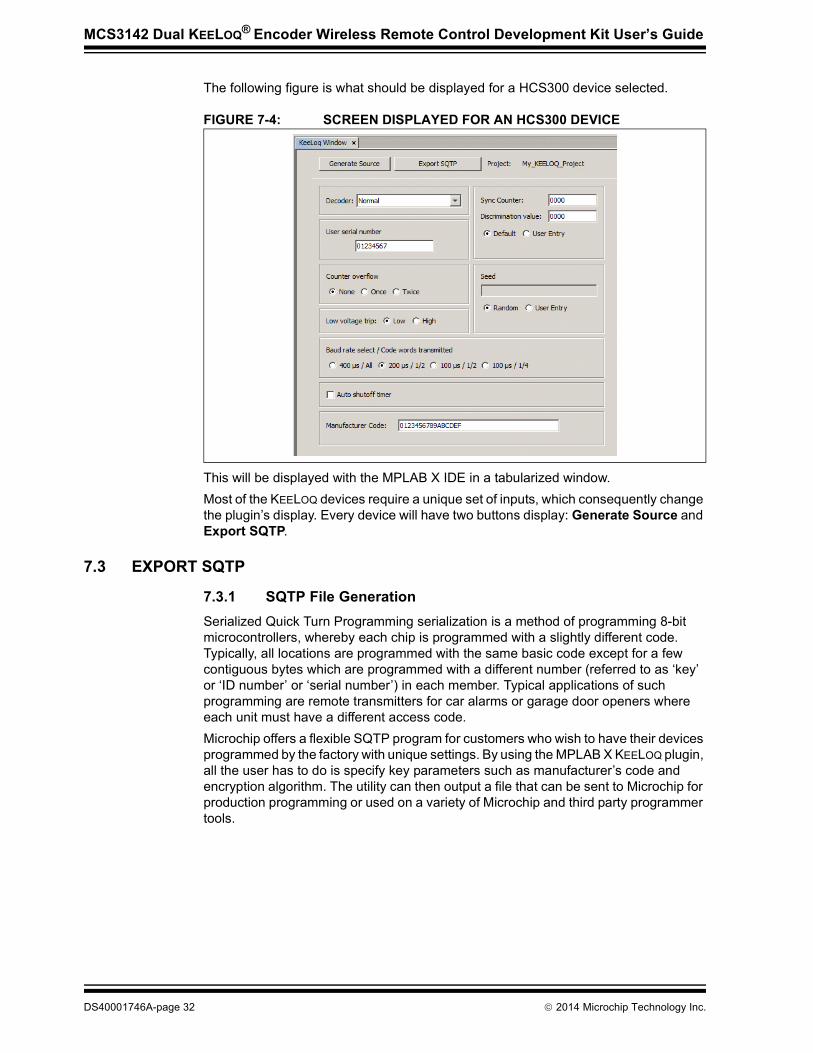
7.2 INSTALLThe plugin requires an existing MPLAB X project with an appropriate KEELOQ device selected as its target to be set as the main project. The tool uses the current main project inside of MPLAB X to select the correct device and workspace to attach the generated code. The KEELOQ plugin is available from the Plugin Center of MPLAB X.To manually install, open up MPLAB X and browse to: Tools->Plugins->Avail-able Plugins and then locate the KEELOQ plugin in the available plugins list. 1. An MPLAB X project must first be created or opened with the correct KEELOQ
device selected. Select File->New Project to start a new project. Follow the rest of the steps, making sure to select a device from the KEELOQ Family.
FIGURE 7-1: SELECTING AN HCS200 KEELOQ DEVICE IN STEP 2 OF THE NEW PROJECT CREATION INSIDE OF MPLAB X
For more information about MPLAB X New Project Creation, please see the MPLAB X documentation.
2014 Microchip Technology Inc. DS40001746A-page 30

KEELOQ MPLAB X Plugin
2. Right-click your project and select Set As Main Project.
FIGURE 7-2: THE KEELOQ® PROJECT MUST BE THE MAIN PROJECT SO THAT THE PLUGIN CORRECTLY RECOGNIZES THE DEVICE
UsageThe plugin can be launched via: Tools->Embedded->Keeloq.
FIGURE 7-3: THE PLUGIN REQUIRES A MAIN PROJECT THAT HAS A KEELOQ® DEVICE SELECTED
The device for this project can be easily modified by: (Right-Click) project-> Properties
Note: Make sure that a KEELOQ device is selected in the main project settings
2014 Microchip Technology Inc. DS40001746A-page 31
MCS3142 Dual KEELOQ® Encoder Wireless Remote Control Development Kit User’s Guide
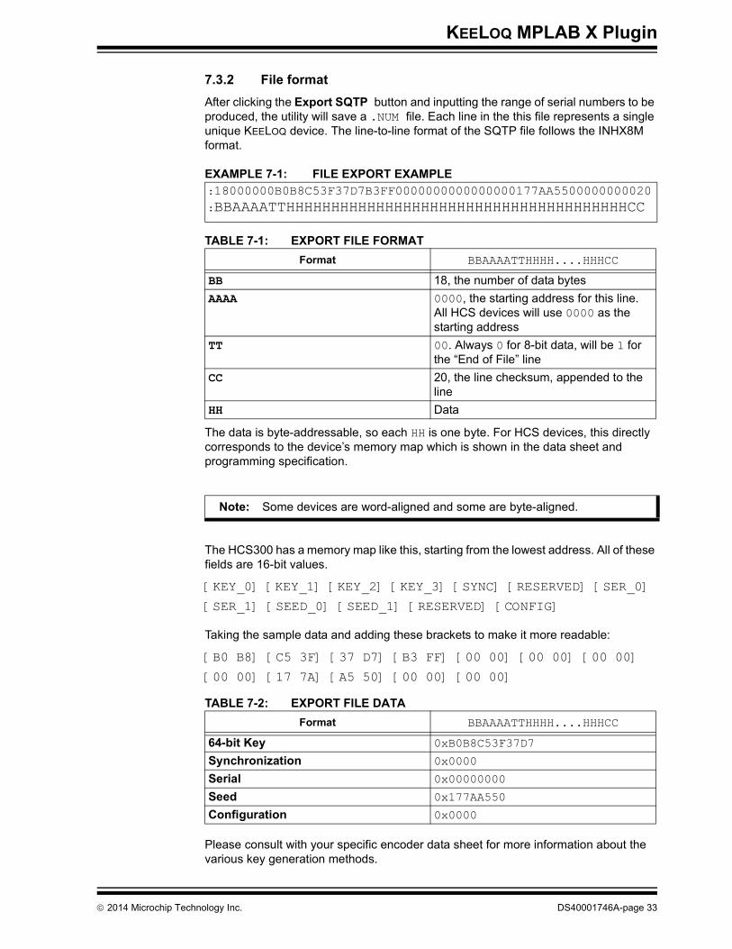
The following figure is what should be displayed for a HCS300 device selected.
FIGURE 7-4: SCREEN DISPLAYED FOR AN HCS300 DEVICE
This will be displayed with the MPLAB X IDE in a tabularized window.Most of the KEELOQ devices require a unique set of inputs, which consequently change the plugin’s display. Every device will have two buttons display: Generate Source and Export SQTP.
7.3 EXPORT SQTP
7.3.1 SQTP File GenerationSerialized Quick Turn Programming serialization is a method of programming 8-bit microcontrollers, whereby each chip is programmed with a slightly different code. Typically, all locations are programmed with the same basic code except for a few contiguous bytes which are programmed with a different number (referred to as ‘key’ or ‘ID number’ or ‘serial number’) in each member. Typical applications of such programming are remote transmitters for car alarms or garage door openers where each unit must have a different access code.Microchip offers a flexible SQTP program for customers who wish to have their devices programmed by the factory with unique settings. By using the MPLAB X KEELOQ plugin, all the user has to do is specify key parameters such as manufacturer’s code and encryption algorithm. The utility can then output a file that can be sent to Microchip for production programming or used on a variety of Microchip and third party programmer tools.
DS40001746A-page 32 2014 Microchip Technology Inc.
KEELOQ MPLAB X Plugin
7.3.2 File formatAfter clicking the Export SQTP button and inputting the range of serial numbers to be produced, the utility will save a .NUM file. Each line in the this file represents a single unique KEELOQ device. The line-to-line format of the SQTP file follows the INHX8M format.
EXAMPLE 7-1: FILE EXPORT EXAMPLE
The data is byte-addressable, so each HH is one byte. For HCS devices, this directly corresponds to the device’s memory map which is shown in the data sheet and programming specification.
The HCS300 has a memory map like this, starting from the lowest address. All of these fields are 16-bit values.
[KEY_0] [KEY_1] [KEY_2] [KEY_3] [SYNC] [RESERVED] [SER_0]
[SER_1] [SEED_0] [SEED_1] [RESERVED] [CONFIG]
Taking the sample data and adding these brackets to make it more readable:
[B0 B8] [C5 3F] [37 D7] [B3 FF] [00 00] [00 00] [00 00]
[00 00] [17 7A] [A5 50] [00 00] [00 00]
Please consult with your specific encoder data sheet for more information about the various key generation methods.
TABLE 7-1: EXPORT FILE FORMATFormat BBAAAATTHHHH....HHHCC
BB 18, the number of data bytesAAAA 0000, the starting address for this line.
All HCS devices will use 0000 as the starting address
TT 00. Always 0 for 8-bit data, will be 1 for the “End of File” line
CC 20, the line checksum, appended to the line
HH Data
:18000000B0B8C53F37D7B3FF0000000000000000177AA5500000000020
:BBAAAATTHHHHHHHHHHHHHHHHHHHHHHHHHHHHHHHHHHHHHHCC
Note: Some devices are word-aligned and some are byte-aligned.
TABLE 7-2: EXPORT FILE DATAFormat BBAAAATTHHHH....HHHCC
64-bit Key 0xB0B8C53F37D7
Synchronization 0x0000
Serial 0x00000000
Seed 0x177AA550
Configuration 0x0000
2014 Microchip Technology Inc. DS40001746A-page 33
MCS3142 Dual KEELOQ® Encoder Wireless Remote Control Development Kit User’s Guide
7.3.3 Generate SourceThe utility helps streamline the process of configuration generation to the physical programming of a KEELOQ device. The Generate Source button will place a single assembly file labeled MemoryMap.asm into the project’s workspace under Source Files. This file contains the calculated values, such as the encryption key, sync, serial, etc, to be placed into programming memory. The user can now connect to the programmer and Flash a KEELOQ device. To program the KEELOQ device, simply click on the Make and Program Device Main Project button located on the MPLAB X toolbar.
DS40001746A-page 34 2014 Microchip Technology Inc.
MCS3142 DUAL KEELOQ® ENCODERWIRELESS REMOTE CONTROL
DEVELOPMENT KIT USER’S GUIDE
Chapter 8. PC Application
8.1 INTRODUCTIONThe MCS3142 can be used in conjunction with a PC application in order to view and edit data.
8.1.1 PC Application Features• View graphically all KEELOQ transactions• Graphical calculator• Change receiver settings• Tooltip text for every data entry
8.1.2 PC RequirementsThe application is cross-platformed and has been tested for the following operating systems:• Windows® XP, Vista, 7, 8• Mac OS® X (Intel) 10.7 and later• Linux (Intel x86/x64)It also requires the Java Runtime Environment (JRE) version 6 or later.Please note the version restriction on the Mac OS X platform. Mac OSX 10.7+ is a restriction from using the MCP2200 as a USB<->Serial device. Only MAC platforms that meet this requirement will be able to correctly connect to the board.
8.2 INSTALLATION
8.2.1 Installing the Wireless Security Remote Kit GUIThe installer can be downloaded from the Microchip website at: http://www.micro-chip.com/keeloq. Install the program by following the installation instructions that come with the package installer.
8.2.2 Installing the MCP2200 USB DriverThe MCP2200 is a USB-to-UART serial converter which enables USB connectivity in application that have a UART interface. The installer includes this driver if installing on a Windows machine. Additionally, the Windows installer can be downloaded here: www.microchip.com/mcp2200.Mac OS X 10.7 or later systems do not need any driver installation.In order to be able to use the MCP2200 with Linux, the kernel must have support for USB CDC class drivers. For more information, Linux users should read the readme installation notes found here: http://ww1.microchip.com/downloads/en/Device-Doc/mcp2200_linux_driver_readme.txt.
2014 Microchip Technology Inc. DS40001746A-page 35

MCS3142 Dual KEELOQ® Encoder Wireless Remote Control Development Kit User’s Guide
8.3 PC QUICK-START
8.3.1 Connecting to the boardUpon launching the application, a similar diagram will be displayed:
FIGURE 8-1: MAIN LANDING SCREEN
Please note that the subsequent screen captures of the program may change in later releases of the program software. A default Windows 7 look and feel was used for all figures. Place the jumper on J6 on the Embedded Security Development Board in its left-most position to enable USB power. Fit the SX1239 Receiver PICtail into its slot on the demo board. Connect a USB cable into the Embedded Security Development Board. D2 should now be lit. In Windows, a notification stating that the MCP2200 device was installed and found successfully will show. If not, the MCP2200 driver may need to be installed manually as stated in the Section 8.2 “Installation”.
DS40001746A-page 36 2014 Microchip Technology Inc.
PC Application
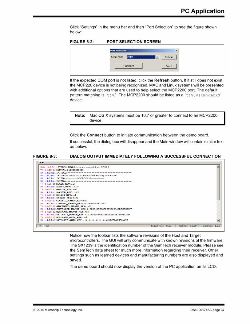
Click “Settings” in the menu bar and then “Port Selection” to see the figure shown below:
FIGURE 8-2: PORT SELECTION SCREEN
If the expected COM port is not listed, click the Refresh button. If it still does not exist, the MCP220 device is not being recognized. MAC and Linux systems will be presented with additional options that are used to help select the MCP2200 port. The default pattern matching is `tty.`. The MCP2200 should be listed as a `tty.usbmodemXX` device.
Click the Connect button to initiate communication between the demo board. If successful, the dialog box will disappear and the Main window will contain similar text as below:
FIGURE 8-3: DIALOG OUTPUT IMMEDIATELY FOLLOWING A SUCCESSFUL CONNECTION
Notice how the toolbar lists the software revisions of the Host and Target microcontrollers. The GUI will only communicate with known revisions of the firmware. The SX1239 is the identification number of the SemTech receiver module. Please see the SemTech data sheet for much more information regarding their receiver. Other settings such as learned devices and manufacturing numbers are also displayed and saved. The demo board should now display the version of the PC application on its LCD.
Note: Mac OS X systems must be 10.7 or greater to connect to an MCP2200 device.
2014 Microchip Technology Inc. DS40001746A-page 37
MCS3142 Dual KEELOQ® Encoder Wireless Remote Control Development Kit User’s Guide
8.3.2 Viewing DataEach of the three KEELOQ technologies contains two panels. One is a graphical view and another is a textual-based logger with an accompanying table with two available rows. Each row of the table represents a single learned device. The Table tab will show relevant information to any learned device that corresponds to its KEELOQ technology. Any data that is changed will momentarily change to a red coloring. The Panel’s tab in which the data changed will also have its tab color change.
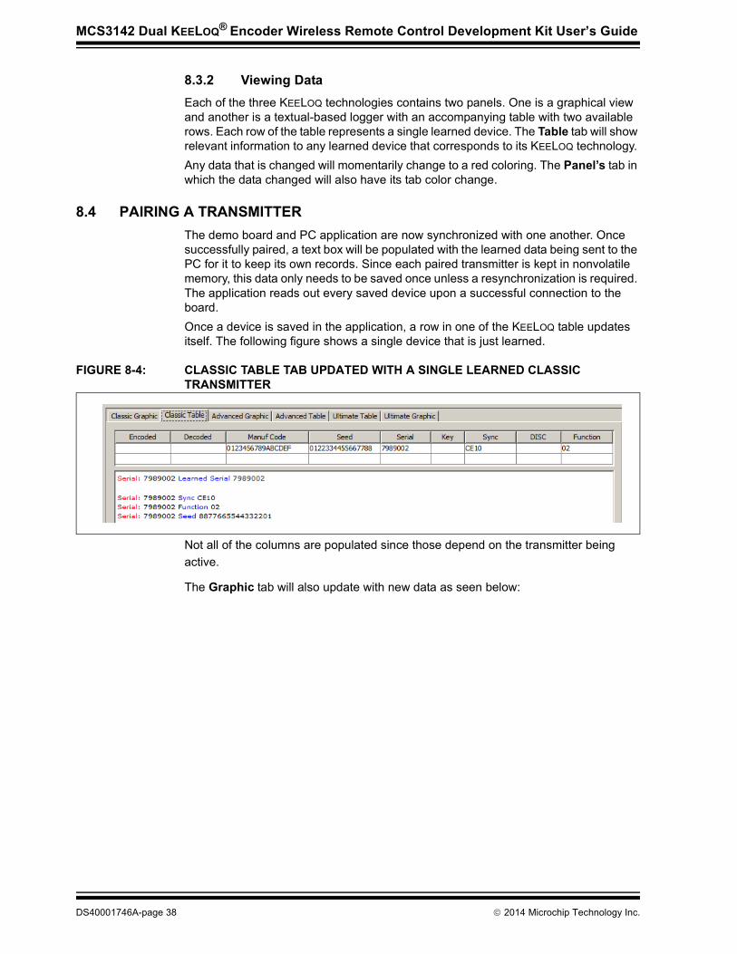
8.4 PAIRING A TRANSMITTERThe demo board and PC application are now synchronized with one another. Once successfully paired, a text box will be populated with the learned data being sent to the PC for it to keep its own records. Since each paired transmitter is kept in nonvolatile memory, this data only needs to be saved once unless a resynchronization is required. The application reads out every saved device upon a successful connection to the board.Once a device is saved in the application, a row in one of the KEELOQ table updates itself. The following figure shows a single device that is just learned.
FIGURE 8-4: CLASSIC TABLE TAB UPDATED WITH A SINGLE LEARNED CLASSIC TRANSMITTER
Not all of the columns are populated since those depend on the transmitter being active.
The Graphic tab will also update with new data as seen below:
DS40001746A-page 38 2014 Microchip Technology Inc.

PC Application
FIGURE 8-5: CLASSIC GRAPHIC UPDATED WITH A SINGLE LEARNED CLASSIC TRANSMITTER
8.5 NORMAL OPERATIONThe GUI will update the graphic blocks and text boxes as the Transmit button on the learned fob is pressed. The figures below show the two panels that have been updated after the previously learned device has its transmission received by the demo board.
FIGURE 8-6: CLASSIC TABLE UPDATED WITH A SINGLE TRANSMISSION BY A PREVIOUSLY LEARNED DEVICE
Note: The graphic will always be updated to the most recent transmitter data.
2014 Microchip Technology Inc. DS40001746A-page 39

MCS3142 Dual KEELOQ® Encoder Wireless Remote Control Development Kit User’s Guide
FIGURE 8-7: CLASSIC GRAPHIC UPDATED WITH A SINGLE TRANSMISSION BY A PREVIOUSLY LEARNED DEVICE
8.5.1 KEELOQ Graphic SpecificsEach graphic contains a “Pie” on the right-hand side of the panel. Every KEELOQ technology provides its own set of unique features.
DS40001746A-page 40 2014 Microchip Technology Inc.

PC Application
Classic KEELOQ
The Counter Delta box indicates the difference between two transmitters’ sync counter values. Since the graphic updates only to the latest transmitter received, this value is sometimes invalid until at least two transmissions from a single device are performed. The red circle represents a simplified Synchronization window as shown in Figure 8-8. The size of the pie is arbitrary, but the technique is fundamental.
FIGURE 8-8: SYNCHRONIZATION WINDOW FOR THE CLASSIC KEELOQ ALGORITHM
The synchronization counter is an always-incrementing event counter. It increments whenever a new packet is prepared on the transmitter. Each time a transmission is authenticated, the intended function is executed and the transmission’s synchroniza-tion counter value is stored in EEPROM. From the currently stored counter value there is an initial “Single Operation” forward window of 16 codes. This 16-code “window” is represented by the dotted blue line. The current sync value is represented by the black line and the previous received by the blue line.
FIGURE 8-9: COUNTER DELTA 1
If the difference between a received synchronization counter and the last stored counter is within 16, the intended function will be executed on the single button press and the new synchronization counter will be stored. Storing the new synchronization counter value effectively rotates the entire Synchronization window.
Note: The proportional aspects of the pie have been manipulated so that it is easier to view the fundamental operation
2014 Microchip Technology Inc. DS40001746A-page 41

MCS3142 Dual KEELOQ® Encoder Wireless Remote Control Development Kit User’s Guide
A delta of ‘1’ is typical under normal operation. To easily see this delta grow, press the Transmit button on the fob multiple times while being out of range from the receiver. Then come back towards the receiver and press again. The delta will now be greater than ‘1’. When the sync counter gets to its maximum value, the fob needs to be reprogrammed in order to resume normal operation again.
Advanced KEELOQ
Please see the previous section regarding how the Sync Counter window works. KEELOQ’S Advanced Sync window has identical operation compared to Classic KEELOQ with the exception that Advanced has a larger, 32-bit sync counter.
Ultimate KEELOQ
The pie in the Ultimate KEELOQ graphic uses the time-stamps between the transmitter and receiver to construct a delta.
FIGURE 8-10: ULTIMATE KEELOQ TIME-STAMP WINDOW
In the absence of a transmission, the PC will continuously increment its clock every ¼ second. A transmission will update the Receiver Clock block with the receiver’s time. The transmitter’s time is symbolized by the black line and should land directly in-between the two blue lines. The blue lines represent the acceptable drift between the receiver and transmitter’s clocks. If the receiver has determined that the transmitter is out of sync, it will force a re-sync event. The Receiver +10 secs button can be used to simulate this re-sync event. The Delta Timer block holds the time difference between the receiver’s clock and transmitter’s clock. The KEELOQ block indicates the battery voltage on the recently received transmitter.
8.6 CALCULATORThe GUI can also be used as a graphical calculator. Some of the blocks appear raised than the others, indicating an input. The mouse pointer will also transform into a hand as the mouse hovers over a raised block. These special blocks are inputs to the calculator and can be used to manipulate the graphic.
After applying the changes, the graphic will update itself from the new stimulus. Note that the effects are not saved to the transmitter, receiver, or inside the learned devices table. These changes do not persist between sessions.
Note: All inputs to the system are in hexadecimal format.
DS40001746A-page 42 2014 Microchip Technology Inc.

PC Application
8.7 RECEIVER SETTINGSThe receiver settings can manipulated via the GUI. To access these options, navigate to Settings->Board Options to see a similar screen as below:
FIGURE 8-11: BOARD SETTINGS DIALOG
The drop-down options for the center frequency contain common settings for the receiver. The Hex input box provides a convenient way to visual the decimal frequency in a hexadecimal format. The modulation can also be configured between OOK and FSK. When satisfied, press the Program Receiver button to apply the changes to the board. The kits come with a receiver that has a matching circuit that is designed to a specific frequency. Changing the frequency far from its originally designed center frequency will have adverse affects on the receiving range.
8.8 VERSIONINGIt is advised that the latest PC application and Host/Target firmware be downloaded from the web at www.microchip.com/keeloq. The Help window will list the firmware of the development board and of the application.
References1. AN1265 – KEELOQ® with AES Microcontroller-Based Code Hopping Encoder2. DS41646 – Wireless Security Remote Control Development Kit User’s Guide3. MCS3142 Dual KEELOQ® Encoder Data sheet4. DS41378 – KEELOQ 3 Development Kit
Note: These settings will not persist between power cycles of the demo board.
2014 Microchip Technology Inc. DS40001746A-page 43
MCS3142 DUAL KEELOQ® ENCODERWIRELESS REMOTE CONTROL
DEVELOPMENT KIT USER’S GUIDE
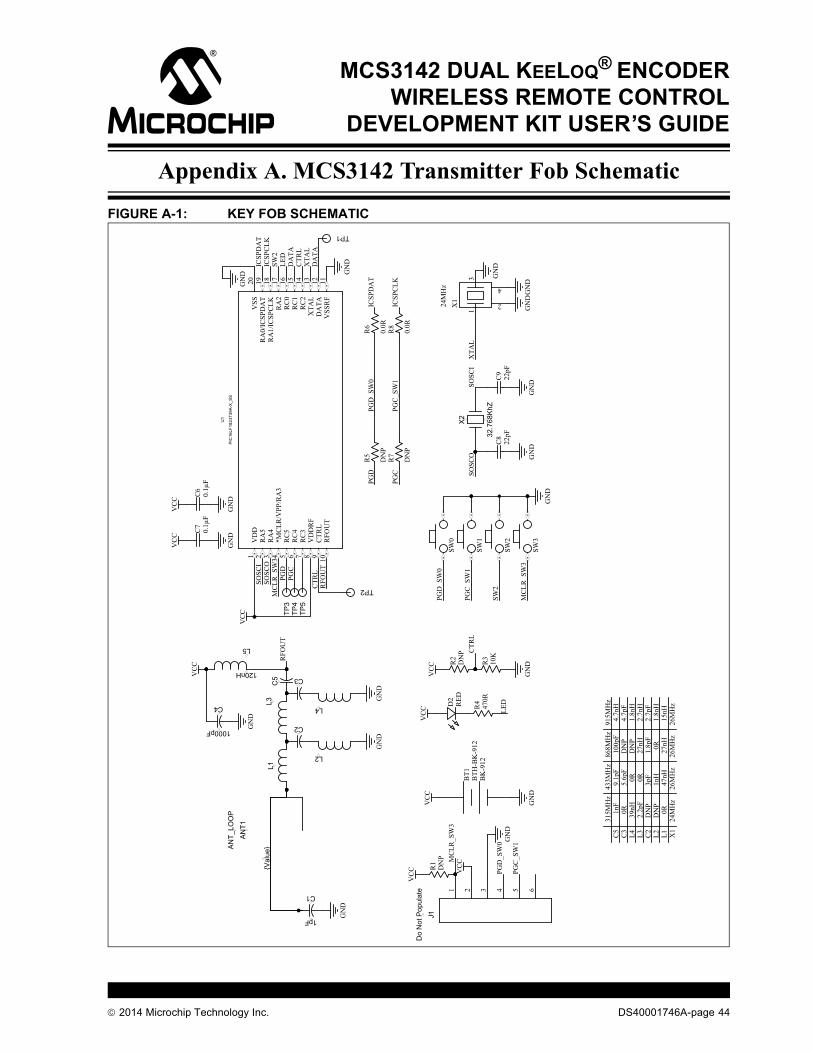
Appendix A. MCS3142 Transmitter Fob Schematic
FIGURE A-1: KEY FOB SCHEMATICVC
C
GN
D
BK
-912
BT1
BTH
-BK
-912
Do
Not
Pop
ulat
e 41 632 5
J1
VC
C
GN
D
PIC
16LF
1824
T39A
-X_S
S
VD
D1
RA
52
RA
43
*MC
LR/V
PP/R
A3
4
RC
55
RC
46
RC
37
VD
DR
F8
CTR
L9
RFO
UT
10V
SSR
F11
DA
TA12
XTA
L13
RC
214
RC
115
RC
016
RA
217
RA
1/IC
SPC
LK18
RA
0/IC
SPD
AT
19V
SS20
U1
470R
R4D2
RED
32.7
68Kh
Z
X2
22pF
C8
22pF
C9
DN
PR
1
C2
C3
C5
1000pF
C4
GN
DG
ND
RFO
UT
RFO
UT
DA
TA
DA
TA
GN
DG
ND
GN
DG
ND
GN
D
GN
D
VC
C
VC
C
VC
C
1pF
C1
VC
C
VC
C
GN
D
GN
D
PGD
_SW
0
PGC
_SW
1
LED
SW2
XTA
L
SOSC
ISO
SCO
MC
LR_S
W3
SOSC
ISO
SCO
{Val
ue}
AN
T1
AN
T_LO
OP
TP2
TP1
LED
SW0
SW1
SW2
SW3
PGD
_SW
0
PGC
_SW
1
SW2
MC
LR_S
W3
DN
PR
2
VC
C 10K
R3
GN
D
CTR
L
CTR
L
24M
Hz
13
2
4
X1
XTA
L
GN
D
GN
DG
ND
GN
D
L1L3
L2
L4
120nH
L5
MC
LR_S
W3
PGD
_SW
0
PGC
_SW
1
315M
Hz
433M
Hz
868M
Hz
915M
Hz
C5
C3
L4 L3 C2
L2 L1 X1
0.1µ
FC
60.
1µF
C7
CTR
L
VC
C
TP3
TP4
TP5
0.0R
R6
0.0R
R8
DN
P
R5
DN
P
R7
ICSP
CLK
ICSP
DA
TPG
D
PGC
PGD
PGC
ICSP
DA
TIC
SPC
LK
0R0R 0R
0R0R
DN
PD
NP
DN
PD
NP
1nF
39nH
2.2p
F
24M
Hz
26M
Hz
26M
Hz
26M
Hz
9.1p
F5.
6pF
3pF
1nH
47nH
100p
F
27nH
1.8p
F
27nH
4.7n
H4.
7pF
1.8n
H2.
7nH
2.7p
F1.
8nH
15nH
2014 Microchip Technology Inc. DS40001746A-page 44
MCS3142 Transmitter Fob Schematic
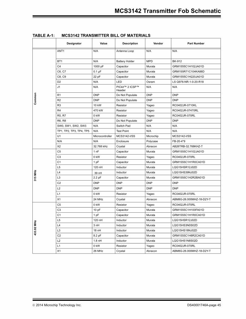
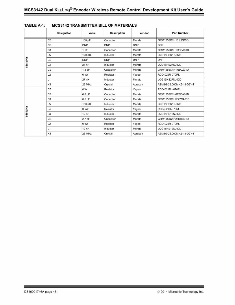
TABLE A-1: MCS3142 TRANSMITTER BILL OF MATERIALS
Designator Value Description Vendor Part Number
Com
mon
ANT1 N/A Antenna Loop N/A N/A
BT1 N/A Battery Holder MPD BK-912
C4 1000 pF Capacitor Murata GRM1555C1H102JA01D
C6, C7 0.1 µF Capacitor Murata GRM155R71C104KA88D
C8, C9 22 pF Capacitor Murata GRM1555C1H220JA01D
D2 N/A LED Osram LS Q976-NR-1-0-20-R18
J1 N/A PICkit™ 2 ICSP™ Header
N/A N/A
R1 DNP Do Not Populate DNP DNP
R2 DNP Do Not Populate DNP DNP
R3 10 kW Resistor Yageo RC0402JR-0710KL
R4 470 kW Resistor Yageo RC0402JR-07470RL
R5, R7 0 kW Resistor Yageo RC0402JR-070RL
R6, R8 DNP Do Not Populate DNP DNP
SW0, SW1, SW2, SW3 N/A Switch Pad N/A N/A
TP1, TP2, TP3, TP4, TP5 N/A Test Point N/A N/A
U1 Microcontroller MCS3142-I/SS Microchip MCS3142-I/SS
N/A N/A Enclosure Polycase FB-20-4*9
X2 32.768 kHz Crystal Abracon AB26TRB-32.768KHZ-T
315
MH
z
C5 1 nF Capacitor Murata GRM1555C1H102JA01D
C3 0 kW Resistor Yageo RC0402JR-070RL
C1 1 pF Capacitor Murata GRM1555C1H1R0CA01D
L5 120 nH Inductor Murata LQG15HSR12J02D
L4 39 nH Inductor Murata LQG15HS39NJ02D
L3 2.2 pF Capacitor Murata GRM1555C1H2R2BA01D
C2 DNP DNP DNP DNP
L2 DNP DNP DNP DNP
L1 0 kW Resistor Yageo RC0402JR-070RL
X1 24 MHz Crystal Abracon ABM8G-26.000MHZ-18-D2Y-T
433.
92 M
Hz
C5 0 kW Resistor Yageo RC0402JR-070RL
C3 10 pF Capacitor Murata GRM1555C1H100FA01D
C1 1 pF Capacitor Murata GRM1555C1H1R0CA01D
L5 120 nH Inductor Murata LQG15HSR12J02D
L4 3 nH Inductor Murata LQG15HS3N0S02D
L3 18 nH Inductor Murata LQG15HS18NJ02D
C2 8.2 pF Capacitor Murata GRM1555C1H8R2CA01D
L2 1.8 nH Inductor Murata LQG15HS1N8S02D
L1 0 kW Resistor Yageo RC0402JR-070RL
X1 26 MHz Crystal Abracon ABM8G-26.000MHZ-18-D2Y-T
2014 Microchip Technology Inc. DS40001746A-page 45
MCS3142 Dual KEELOQ® Encoder Wireless Remote Control Development Kit User’s Guide
868
MH
z
C5 100 pF Capacitor Murata GRM1555C1H101JDD5D
C3 DNP DNP DNP DNP
C1 1 pF Capacitor Murata GRM1555C1H1R0CA01D
L5 120 nH Inductor Murata LQG15HSR12J02D
L4 DNP DNP DNP DNP
L3 27 nH Inductor Murata LQG15HS27NJ02D
C2 1.8 pF Capacitor Murata GRM1555C1H1R8CZ01D
L2 0 kW Resistor Yageo RC0402JR-070RL
L1 27 nH Inductor Murata LQG15HS27NJ02D
X1 26 MHz Crystal Abracon ABM8G-26.000MHZ-18-D2Y-T
915
MH
z
C5 0 W Resistor Yageo RC0402JR - 070RL
C3 6.8 pF Capacitor Murata GRM1555C1H6R8DA01D
C1 0.5 pF Capacitor Murata GRM1555C1HR50WA01D
L5 150 nH Inductor Murata LQG15HSR15J02D
L4 0 kW Resistor Yageo RC0402JR-070RL
L3 12 nH Inductor Murata LQG15HS12NJ02D
C2 2.7 pF Capacitor Murata GRM1555C1H2R7BA01D
L2 0 kW Resistor Yageo RC0402JR-070RL
L1 12 nH Inductor Murata LQG15HS12NJ02D
X1 26 MHz Crystal Abracon ABM8G-26.000MHZ-18-D2Y-T
TABLE A-1: MCS3142 TRANSMITTER BILL OF MATERIALS
Designator Value Description Vendor Part Number
DS40001746A-page 46 2014 Microchip Technology Inc.
MCS3142 DUAL KEELOQ® ENCODERWIRELESS REMOTE CONTROL
DEVELOPMENT KIT USER’S GUIDE
Appendix B. SX1239 Receiver PICtail™ Daughter Board Schematics
FIGURE B-1: SX1239 RECEIVER PICtail™ PCB ASSEMBLY
2014 Microchip Technology Inc. DS40001746A-page 47

MCS3142 Dual KEELOQ® Encoder Wireless Remote Control Development Kit User’s Guide
FIGURE B-2: RECEIVER PICtail™ SCHEMATIC
15pF
C9
15pFC
8
0.1µ
FC
40.
1µF
C3
+3.3
V
0.1µ
FC
70.
1µF
C6
DN
PL
17.
5nH
C1
5.6p
FC
52.
7pF
C2
DN
PL
2
Ant
enna
Con
nect
ion
SX12
39IM
LT
RT
VB
AT
11
VR
_AN
A2
VR
_DIG
3
NC
24
SCK
15
MO
SI17
NSS
18
RE
SET
6
XT
A4
XT
B5
GN
D14
GN
D20
GN
D22
PAD
25
VB
AT
213
RFI
O21
DIO
07
DIO
1/D
CL
K8
DIO
2/D
AT
A9
DIO
310
DIO
411
DIO
512
MIS
O16
NC
19
NC
23
U1
SCK
MO
SIN
SS
MIS
O
MIS
OM
OSI
SCK
NSS
RE
SET
12
34
56
78
910
1112
1314
1516
1718
1920
21 23 25 27
22 24 26 28
J1
RE
SET
DIO
0D
IO1
DIO
2
DIO
0
DIO
1
DIO
2
+3.3
V
1
2E1
TP1
TP2
TP3
13
2
4
32.0
000M
Hz
Y1
1 2 3
4 5 6E
G13
90A
S1
3050
/1 Y
L00
5
A1
DS40001746A-page 48 2014 Microchip Technology Inc.
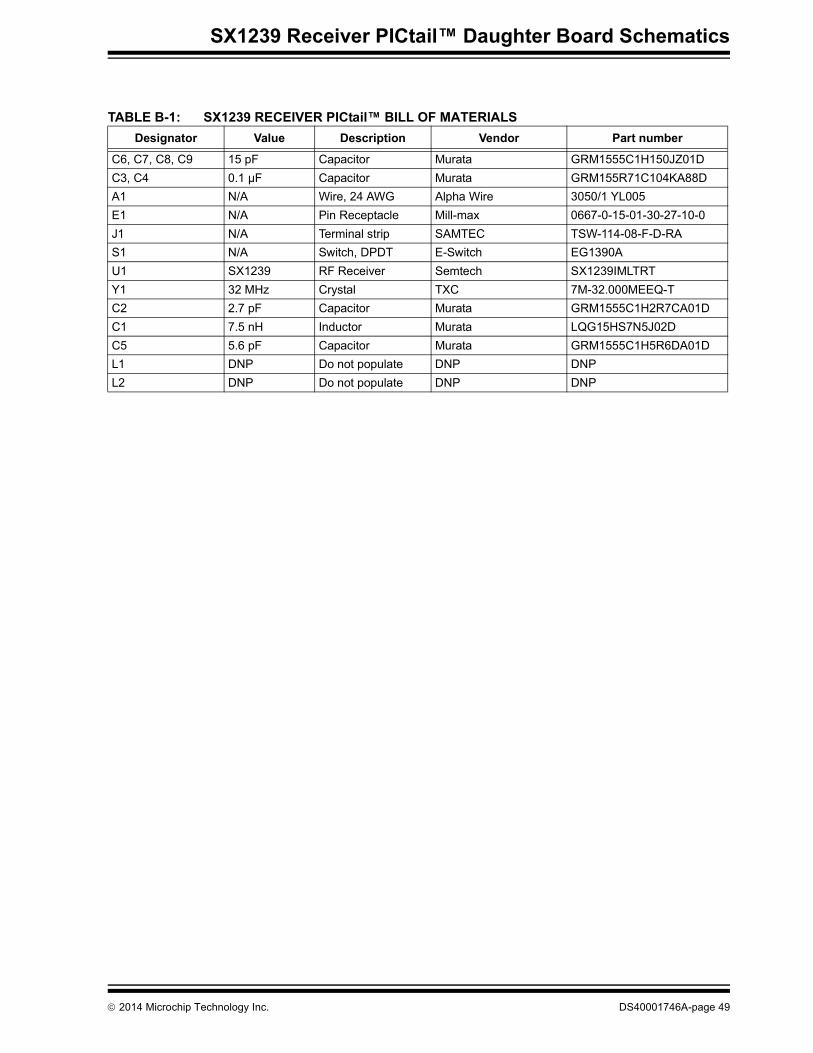
SX1239 Receiver PICtail™ Daughter Board Schematics
TABLE B-1: SX1239 RECEIVER PICtail™ BILL OF MATERIALSDesignator Value Description Vendor Part number
C6, C7, C8, C9 15 pF Capacitor Murata GRM1555C1H150JZ01DC3, C4 0.1 µF Capacitor Murata GRM155R71C104KA88DA1 N/A Wire, 24 AWG Alpha Wire 3050/1 YL005E1 N/A Pin Receptacle Mill-max 0667-0-15-01-30-27-10-0J1 N/A Terminal strip SAMTEC TSW-114-08-F-D-RAS1 N/A Switch, DPDT E-Switch EG1390AU1 SX1239 RF Receiver Semtech SX1239IMLTRTY1 32 MHz Crystal TXC 7M-32.000MEEQ-TC2 2.7 pF Capacitor Murata GRM1555C1H2R7CA01DC1 7.5 nH Inductor Murata LQG15HS7N5J02DC5 5.6 pF Capacitor Murata GRM1555C1H5R6DA01DL1 DNP Do not populate DNP DNPL2 DNP Do not populate DNP DNP
2014 Microchip Technology Inc. DS40001746A-page 49
MCS3142 DUAL KEELOQ® ENCODERWIRELESS REMOTE CONTROL
DEVELOPMENT KIT USER’S GUIDE
Appendix C. Embedded Security Development Board Schematics
FIGURE C-1: EMBEDDED SECURITY DEVELOPMENT BOARD PCB ASSEMBLY
2014 Microchip Technology Inc. DS40001746A-page 50
Embedded Security Development Board Schematics
FIGURE C-2: HOST CONTROLLER OF THE EMBEDDED SECURITY DEVELOPMENT BOARD SCHEMATIC
2014 Microchip Technology Inc. DS40001746A-page 51
MCS3142 Dual KEELOQ® Encoder Wireless Remote Control Development Kit User’s Guide
FIGURE C-3: TARGET APPLICATION OF THE EMBEDDED SECURITY DEVELOPMENT BOARD SCHEMATIC
DS40001746A-page 52 2014 Microchip Technology Inc.

Embedded Security Development Board Schematics
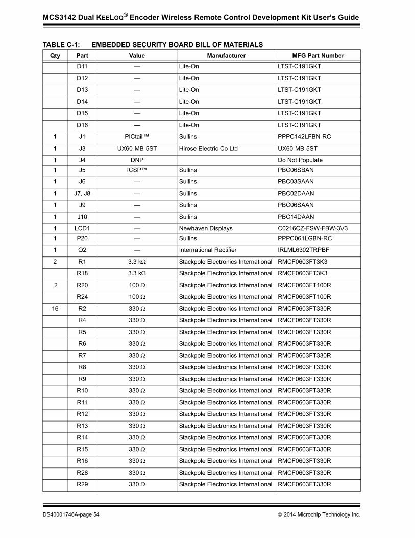
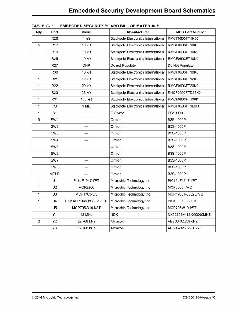
TABLE C-1: EMBEDDED SECURITY BOARD BILL OF MATERIALSQty Part Value Manufacturer MFG Part Number
1 VDD VDD Keystone 5010
GND GND Keystone 5011
1 BT1 BK-885 MPD BK-8853 C8 8 pF TDK Corporation C1608C0G1H080D
C9 8 pF TDK Corporation C1608C0G1H080D
C17 8 pF TDK Corporation C1608C0G1H080D
2 C10 9 pF TDK Corporation C1608C0G1H090D
C11 9 pF TDK Corporation C1608C0G1H090D
1 C18 10 pF TDK Corporation C1608C0G1H100D
1 C19 100 pF TDK Corporation C1608C0G1H101J
11 C1 0.1 µF Murata GRM188R71E104KA01D
C2 0.1 µF Murata GRM188R71E104KA01D
C3 0.1 µF Murata GRM188R71E104KA01D
C4 0.1 µF Murata GRM188R71E104KA01D
C5 0.1 µF Murata GRM188R71E104KA01D
C6 0.1 µF Murata GRM188R71E104KA01D
C7 0.1 µF Murata GRM188R71E104KA01D
C14 0.1 µF Murata GRM188R71E104KA01D
C16 0.1 µF Murata GRM188R71E104KA01D
C21 0.1 µF Murata GRM188R71E104KA01D
C22 0.1 µF Murata GRM188R71E104KA01D
5 C12 1 µF Murata GRM188R61A105MA61D
C13 1 µF Murata GRM188R61A105MA61D
C15 1 µF Murata GRM188R61A105MA61D
C20 1 µF Murata GRM188R61A105MA61D
C23 1 µF Murata GRM188R61A105MA61D
1 D1 B0520WS Diodes Inc. B0520WS-7-F
1 D3 — Fairchild Semiconductor BAT54 D2 — Lite-On LTST-C191GKT
D4 — Lite-On LTST-C191GKT
D5 — Lite-On LTST-C191GKT
D6 — Lite-On LTST-C191GKT
D7 — Lite-On LTST-C191GKT
D8 — Lite-On LTST-C191GKT
D9 — Lite-On LTST-C191GKT
D10 — Lite-On LTST-C191GKT
2014 Microchip Technology Inc. DS40001746A-page 53
MCS3142 Dual KEELOQ® Encoder Wireless Remote Control Development Kit User’s Guide
D11 — Lite-On LTST-C191GKT
D12 — Lite-On LTST-C191GKT
D13 — Lite-On LTST-C191GKT
D14 — Lite-On LTST-C191GKT
D15 — Lite-On LTST-C191GKT
D16 — Lite-On LTST-C191GKT
1 J1 PICtail™ Sullins PPPC142LFBN-RC
1 J3 UX60-MB-5ST Hirose Electric Co Ltd UX60-MB-5ST
1 J4 DNP Do Not Populate1 J5 ICSP™ Sullins PBC06SBAN
1 J6 — Sullins PBC03SAAN
1 J7, J8 — Sullins PBC02DAAN
1 J9 — Sullins PBC06SAAN
1 J10 — Sullins PBC14DAAN
1 LCD1 — Newhaven Displays C0216CZ-FSW-FBW-3V31 P20 — Sullins PPPC061LGBN-RC
1 Q2 — International Rectifier IRLML6302TRPBF
2 R1 3.3 k Stackpole Electronics International RMCF0603FT3K3
R18 3.3 k Stackpole Electronics International RMCF0603FT3K3
2 R20 100 Stackpole Electronics International RMCF0603FT100R
R24 100 Stackpole Electronics International RMCF0603FT100R
16 R2 330 Stackpole Electronics International RMCF0603FT330R
R4 330 Stackpole Electronics International RMCF0603FT330R
R5 330 Stackpole Electronics International RMCF0603FT330R
R6 330 Stackpole Electronics International RMCF0603FT330R
R7 330 Stackpole Electronics International RMCF0603FT330R
R8 330 Stackpole Electronics International RMCF0603FT330R
R9 330 Stackpole Electronics International RMCF0603FT330R
R10 330 Stackpole Electronics International RMCF0603FT330R
R11 330 Stackpole Electronics International RMCF0603FT330R
R12 330 Stackpole Electronics International RMCF0603FT330R
R13 330 Stackpole Electronics International RMCF0603FT330R
R14 330 Stackpole Electronics International RMCF0603FT330R
R15 330 Stackpole Electronics International RMCF0603FT330R
R16 330 Stackpole Electronics International RMCF0603FT330R
R28 330 Stackpole Electronics International RMCF0603FT330R
R29 330 Stackpole Electronics International RMCF0603FT330R
TABLE C-1: EMBEDDED SECURITY BOARD BILL OF MATERIALSQty Part Value Manufacturer MFG Part Number
DS40001746A-page 54 2014 Microchip Technology Inc.
Embedded Security Development Board Schematics
1 R26 1 k Stackpole Electronics International RMCF0603FT1K00
5 R17 10 k Stackpole Electronics International RMCF0603FT10K0
R19 10 k Stackpole Electronics International RMCF0603FT10K0
R25 10 k Stackpole Electronics International RMCF0603FT10K0
R27 DNP Do not Populate Do Not Populate
R30 10 k Stackpole Electronics International RMCF0603FT10K0
1 R21 12 k Stackpole Electronics International RMCF0603FT12K0
1 R22 20 k Stackpole Electronics International RMCF0603FT20K0
1 R23 28 k Stackpole Electronics International RNCP0603FTD28K0
1 R31 100 k Stackpole Electronics International RMCF0603FT100K
1 R3 1 M Stackpole Electronics International RMCF0603FT1M00
1 S1 — E-Switch EG1390B
9 SW1 — Omron B3S-1000P
SW2 — Omron B3S-1000P
SW3 — Omron B3S-1000P
SW4 — Omron B3S-1000P
SW5 — Omron B3S-1000P
SW6 — Omron B3S-1000P
SW7 — Omron B3S-1000P
SW8 — Omron B3S-1000P
MCLR — Omron B3S-1000P
1 U1 P16LF1947-I/PT Microchip Technology Inc. PIC16LF1947-I/PT
1 U2 MCP2200 Microchip Technology Inc. MCP2200-I/MQ
1 U3 MCP1703-3.3 Microchip Technology Inc. MCP1703T-3302E/MB
1 U4 PIC16LF1938-I/SS_28-PIN Microchip Technology Inc. PIC16LF1938-I/SS
1 U5 MCP795W10-I/ST Microchip Technology Inc. MCP795W10-I/ST
1 Y1 12 MHz NDK NX3225SA-12.000000MHZ
2 Y2 32.768 kHz Abracon ABS06-32.768KHZ-T
Y3 32.768 kHz Abracon ABS06-32.768KHZ-T
TABLE C-1: EMBEDDED SECURITY BOARD BILL OF MATERIALSQty Part Value Manufacturer MFG Part Number
2014 Microchip Technology Inc. DS40001746A-page 55

DS40001746A-page 56 2014 Microchip Technology Inc.
AMERICASCorporate Office2355 West Chandler Blvd.Chandler, AZ 85224-6199Tel: 480-792-7200 Fax: 480-792-7277Technical Support: http://www.microchip.com/supportWeb Address: www.microchip.comAtlantaDuluth, GA Tel: 678-957-9614 Fax: 678-957-1455Austin, TXTel: 512-257-3370 BostonWestborough, MA Tel: 774-760-0087 Fax: 774-760-0088ChicagoItasca, IL Tel: 630-285-0071 Fax: 630-285-0075ClevelandIndependence, OH Tel: 216-447-0464 Fax: 216-447-0643DallasAddison, TX Tel: 972-818-7423 Fax: 972-818-2924DetroitNovi, MI Tel: 248-848-4000Houston, TX Tel: 281-894-5983IndianapolisNoblesville, IN Tel: 317-773-8323Fax: 317-773-5453Los AngelesMission Viejo, CA Tel: 949-462-9523 Fax: 949-462-9608New York, NY Tel: 631-435-6000San Jose, CA Tel: 408-735-9110Canada - TorontoTel: 905-673-0699 Fax: 905-673-6509
ASIA/PACIFICAsia Pacific OfficeSuites 3707-14, 37th FloorTower 6, The GatewayHarbour City, KowloonHong KongTel: 852-2401-1200Fax: 852-2401-3431Australia - SydneyTel: 61-2-9868-6733Fax: 61-2-9868-6755China - BeijingTel: 86-10-8569-7000 Fax: 86-10-8528-2104China - ChengduTel: 86-28-8665-5511Fax: 86-28-8665-7889China - ChongqingTel: 86-23-8980-9588Fax: 86-23-8980-9500China - HangzhouTel: 86-571-2819-3187 Fax: 86-571-2819-3189China - Hong Kong SARTel: 852-2943-5100 Fax: 852-2401-3431China - NanjingTel: 86-25-8473-2460Fax: 86-25-8473-2470China - QingdaoTel: 86-532-8502-7355Fax: 86-532-8502-7205China - ShanghaiTel: 86-21-5407-5533 Fax: 86-21-5407-5066China - ShenyangTel: 86-24-2334-2829Fax: 86-24-2334-2393China - ShenzhenTel: 86-755-8864-2200 Fax: 86-755-8203-1760China - WuhanTel: 86-27-5980-5300Fax: 86-27-5980-5118China - XianTel: 86-29-8833-7252Fax: 86-29-8833-7256China - XiamenTel: 86-592-2388138 Fax: 86-592-2388130China - ZhuhaiTel: 86-756-3210040 Fax: 86-756-3210049
ASIA/PACIFICIndia - BangaloreTel: 91-80-3090-4444 Fax: 91-80-3090-4123India - New DelhiTel: 91-11-4160-8631Fax: 91-11-4160-8632India - PuneTel: 91-20-3019-1500Japan - OsakaTel: 81-6-6152-7160 Fax: 81-6-6152-9310Japan - TokyoTel: 81-3-6880- 3770 Fax: 81-3-6880-3771Korea - DaeguTel: 82-53-744-4301Fax: 82-53-744-4302Korea - SeoulTel: 82-2-554-7200Fax: 82-2-558-5932 or 82-2-558-5934Malaysia - Kuala LumpurTel: 60-3-6201-9857Fax: 60-3-6201-9859Malaysia - PenangTel: 60-4-227-8870Fax: 60-4-227-4068Philippines - ManilaTel: 63-2-634-9065Fax: 63-2-634-9069SingaporeTel: 65-6334-8870Fax: 65-6334-8850Taiwan - Hsin ChuTel: 886-3-5778-366Fax: 886-3-5770-955Taiwan - KaohsiungTel: 886-7-213-7830Taiwan - TaipeiTel: 886-2-2508-8600 Fax: 886-2-2508-0102Thailand - BangkokTel: 66-2-694-1351Fax: 66-2-694-1350
EUROPEAustria - WelsTel: 43-7242-2244-39Fax: 43-7242-2244-393Denmark - CopenhagenTel: 45-4450-2828 Fax: 45-4485-2829France - ParisTel: 33-1-69-53-63-20 Fax: 33-1-69-30-90-79Germany - DusseldorfTel: 49-2129-3766400Germany - MunichTel: 49-89-627-144-0 Fax: 49-89-627-144-44Germany - PforzheimTel: 49-7231-424750Italy - Milan Tel: 39-0331-742611 Fax: 39-0331-466781Italy - VeniceTel: 39-049-7625286 Netherlands - DrunenTel: 31-416-690399 Fax: 31-416-690340Poland - WarsawTel: 48-22-3325737 Spain - MadridTel: 34-91-708-08-90Fax: 34-91-708-08-91Sweden - StockholmTel: 46-8-5090-4654UK - WokinghamTel: 44-118-921-5800Fax: 44-118-921-5820
Worldwide Sales and Service
10/28/13