MC Benchmarks for LAr Instrumentation in GERDA BENCHMARKS FOR LAR INSTRUMENTATION IN GERDA ... Water...
15
Institut für Kern- und Teilchenphysik MC BENCHMARKS FOR LAR INSTRUMENTATION IN GERDA Nuno Fiuza de Barros on behalf of the GERDA collaboration DPG, Göttingen, 27 February - 2 March 2012
Transcript of MC Benchmarks for LAr Instrumentation in GERDA BENCHMARKS FOR LAR INSTRUMENTATION IN GERDA ... Water...
Institut für Kern- und Teilchenphysik
MC BENCHMARKS FOR LARINSTRUMENTATION IN GERDANuno Fiuza de Barroson behalf of the GERDA collaboration
DPG, Göttingen, 27 February - 2 March 2012

Germanium Detector ArrayDetector design
• Clean room.
• Lock system.
• Water tank (steel).
• Muon veto (Cerenkov).
• Cryostat (steel + Cu).
• Liquid Argon.
• Detector array.
Göttingen, Feb 2012 MC Benchmarks for LAr Instrumentation in GERDA slide 2 of 15

LAr as an active vetoPlans for GERDA
• Instrument the LAr to detect scintillation light.– Veto backgrounds from coincidence between Ge and LAr events.– Principle already demonstrated in test facility (LArGe).– Efficiency dependent of type of background.– Aim implementation for GERDA phase II.
• Two major instrumentation designs (M. Heisel, T 116.1).– Optical fiber design.– PMT design.
Goals for the MC:• Estimate background suppression (veto efficiency) of the design.
• Optimize the design to maximize background suppression.
Göttingen, Feb 2012 MC Benchmarks for LAr Instrumentation in GERDA slide 3 of 15
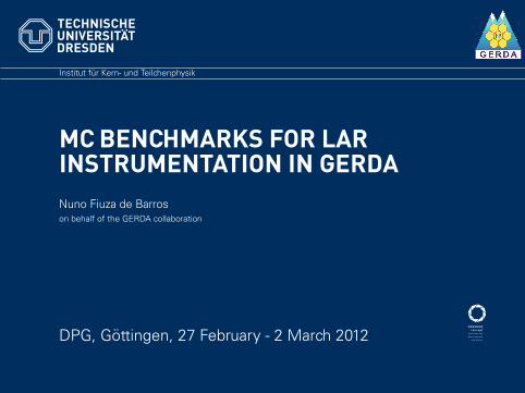
LAr as an active veto
• Detect scintillation light in LAr to tagexternal background events.
• Very high light yield: ∼ 4 × 10⁴
photons/MeV.
• Single re-emission peak (λ = 128 nm).– Not directly detectable.– Use wavelength shifter (eg.
VM2000).
• Some challenges:– Properties strongly affected by
impurities (eg.: Xe, N2).– Short scattering length in emission
range (σ128nm ≈ 80 cm).
• Some advantages:– Very distinctive short and long decay
times (τshort ∼ 6 ns,τlong ∼ 1200 − 1500 ns).
– Transparent in the visible range(σ550nm > 1km). peaks by orders of magnitude. This means that the contribu-
tion of the other peaks can be neglected when using thephotodiode, even though its efficiency increases by a factorof two in the wavelength region of the atomic features. Anyfeatures at wavelengths greater than 1500 Å can also be ne-glected since the photodiode efficiency becomes negligiblefor energies less than 8 eV.The inset of Fig. 3 shows UV and visible features induced
by 30-keV H� corrected for the efficiency of the spectrom-eter �no differences in the spectra were seen for differentenergies of H� from 10–50 keV�. Three features are appar-ent in the spectrum at 1265 Å �9.8 eV�, 1650 Å �7.6 eV�, and2000 Å �6.2 eV�; no other features were seen out to 5000 Å.Similar spectra induced by ion bombardment were measuredby Busch et al.2 and Riemann, Brown, and Johnson.5 Theselatter authors attributed the features at 7.6 eV and 6.2 eV toN2 and O2 impurities,29 respectively. Langhoff30 and Grigo-rashchenko et al.,31 however, attribute the 6.2-eV feature, theso-called ‘‘third continuum’’ in the gas phase, to the decayof (Ar2�Ar) to the repulsive ground state of Ar��Ar�. Analternative explanation is the breakup of impurity water mol-ecules in the film, giving rise to Ar2O and Ar2H lines at 6.2and 7.5 eV reported by Kraas and Gurtler.32 Regardless ofthe origin of these low-energy features, the 9.8-eV featureclearly dominates, accounting for 94% of the energy in thisspectrum.
III. CALCULATION OF ABSOLUTE EFFICIENCY
We determined that the response of the photodiode is di-rectly proportional to the ion-beam current from 0.15 to 400nA. If Id is the current measured on the photodiode and q isthe elementary charge, then the photon flux measured by thephotodiode is given by
Idq f
���
����d� , �1�
where � is the solid angle seen by the photodiode, ���� isthe angular distribution of the luminescence emitted intovacuum, and f�0.017 is the weighted average efficiency ofthe photodiode over the M band.We assume that the initial distribution of luminescence
emission from each source inside the film is unpolarized andisotropic:
�����I04�
, �2�
where I0 is the total number of photons created inside thefilm per second. Self-absorption and scattering within thefilm are neglected; refraction at the Ar/vacuum interfacemodifies the external emission distribution and makes ����anisotropic. Here we assume that the films are flat andsmooth. If ���� represents the internal emission distribution�see Fig. 4�, then ����sin� d���(�)sin� d� , assumingthere are no reflection losses or multiple reflection gains thatneed to be included. Using Snell’s law as well as its differ-ential form, we solve for
�����cos�
n�n2�sin2������ �3�
where n�1.48 is the index of refraction for 10-eV photonsin solid Ar �Ref. 33� and � is a unitless factor that accountsfor substrate reflectivity and surface reflections. These willbe discussed in the paragraphs below. This expression isvalid with the assumption that the film surface is flat on aspatial scale larger than the wavelength of 9.8-eV light.Part of the luminescence will reflect from the substrate
and reach the surface of the film. The substrates had a mir-rorlike finish and are thus assumed to reflect specularly. Thefraction of the light reflecting from the substrate is R(�), thereflectance of the substrate for an incidence angle �, where���. For 10-eV photons, RAu(0)�0.15 and RSi(0)�0.3 forSi with an oxide layer �see the appendix for details of howthese values were obtained�. The fraction of light �unpolar-
FIG. 3. UV luminescence spectrum of a 4000-Å solid Ar filmbombarded by 2-MeV He�. The inset shows a spectrum producedby 30-keV H� on a 4000-Å Ar film that includes lower-energyfeatures. No luminescence features were seen in the range of 2200–5000 Å.
FIG. 4. Geometry for absolute luminescence determination as-suming specular reflection at the substrate.
56 6977ABSOLUTE LUMINESCENCE EFFICIENCY OF ION- . . .
Gosjean, Phys. Rev. B 56(1997)
Göttingen, Feb 2012 MC Benchmarks for LAr Instrumentation in GERDA slide 4 of 15
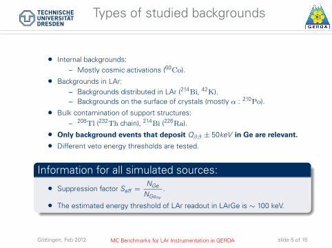
Types of studied backgrounds
• Internal backgrounds:– Mostly cosmic activations (60Co).
• Backgrounds in LAr:– Backgrounds distributed in LAr (214Bi, 42K).– Backgrounds on the surface of crystals (mostly α : 210Po).
• Bulk contamination of support structures:– 208Tl (232Th chain), 214Bi (226Ra).
• Only background events that deposit Qββ ± 50keV in Ge are relevant.
• Different veto energy thresholds are tested.
Information for all simulated sources:
• Suppression factor Seff =NGe
NGenv
.
• The estimated energy threshold of LAr readout in LArGe is ∼ 100 keV.
Göttingen, Feb 2012 MC Benchmarks for LAr Instrumentation in GERDA slide 5 of 15
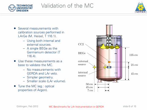
Validation of the MC
• Several measurements withcalibration sources performed inLArGe (M. Heisel, T 116.1).
– Using both internal andexternal sources.
– A single BEGe as theGermanium detector (T116.4).
• Use these measurements as abase to validate the MC.
– No measurements withGERDA and LAr veto.
– Simpler geometry.– Smaller scale (LAr volume).
• Tune the MC (eg.: opticalproperties of Argon).
CC2
BEGe
externalsource
internalsource
50 cm45 cm7 cm
135 cm
21 cm
45 cm
Göttingen, Feb 2012 MC Benchmarks for LAr Instrumentation in GERDA slide 6 of 15
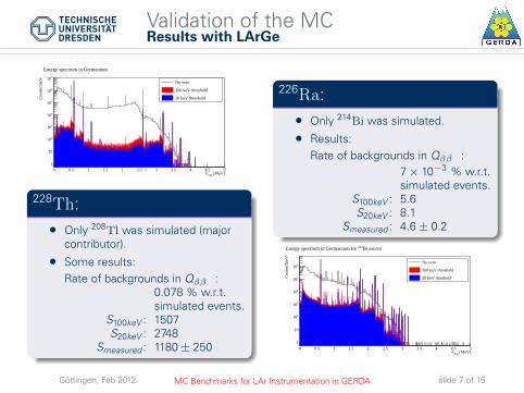
Validation of the MCResults with LArGe
[MeV]depE0 0.5 1 1.5 2 2.5 3 3.5 4 4.5 5
Cou
nts/
5keV
1
10
210
310
410
510
610
710
Energy spectrum in Germanium
No veto
100 keV threshold
20 keV threshold
228Th:• Only 208Tl was simulated (major
contributor).
• Some results:Rate of backgrounds in Qββ :
0.078 % w.r.t.simulated events.
S100keV : 1507S20keV : 2748
Smeasured : 1180 ± 250
226Ra:• Only 214Bi was simulated.
• Results:Rate of backgrounds in Qββ :
7 × 10⁻³ % w.r.t.simulated events.
S100keV : 5.6S20keV : 8.1
Smeasured : 4.6 ± 0.2
[MeV]depE0 0.5 1 1.5 2 2.5 3 3.5 4 4.5 5
Cou
nts/
5keV
1
10
210
310
410
510
610
Bi source214Energy spectrum in Germanium for
No veto
100 keV threshold
20 keV threshold
Göttingen, Feb 2012 MC Benchmarks for LAr Instrumentation in GERDA slide 7 of 15

Validation of the MCResults with LArGe
60Co:• Activation from cosmic rays.
• Some results:Rate of backgrounds in Qββ :
2.93 × 10⁻³ %.S100keV : 55S20keV : 73
Smeasured : 27 ± 1.7. [MeV]depE0 0.5 1 1.5 2 2.5 3
Cou
nts/
5keV
210
310
410
510
610
No veto
100 keV veto threshold
20 keV veto threshold
Energy spectrum in Germanium
Summary of LArGe MC tests:• MC consistent with the experimental measurements.
– The MC is not yet fully tuned.
• Discrepancy in 60Co simulation likely due to imprecise information:– Position of the source.– Design of the BEGe.– Design of the source.– Geometrical effects (shadows).
Göttingen, Feb 2012 MC Benchmarks for LAr Instrumentation in GERDA slide 8 of 15

MC Status for GERDA Phase-I
• Principle similar to LArGe.
• Considerably more complex geometry.– Multiple Ge detectors instead of a single one.– Additional detector components (holders, cables).
• Simulations of major backgrounds estimated through the deposited energy:– These tests do not yet allow to properly compare designs.– It serves as an indication of the best possible scenario for the veto.
Göttingen, Feb 2012 MC Benchmarks for LAr Instrumentation in GERDA slide 9 of 15
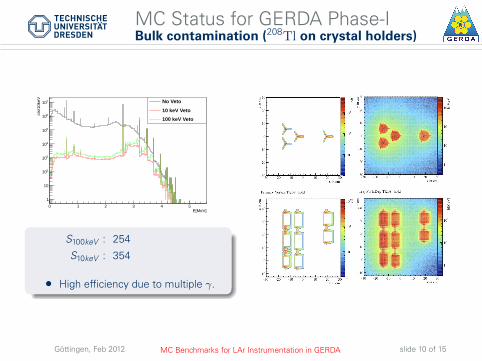
MC Status for GERDA Phase-IBulk contamination (208Tl on crystal holders)
E[MeV]0 1 2 3 4 5
cts
/10k
eV
1
10
210
310
410
510
610
710 No Veto
10 keV Veto
100 keV Veto
S100keV : 254
S10keV : 354
• High efficiency due to multiple γ.
Göttingen, Feb 2012 MC Benchmarks for LAr Instrumentation in GERDA slide 10 of 15
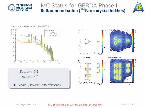
MC Status for GERDA Phase-IBulk contamination (214Bi on crystal holders)
E[MeV]0 0.5 1 1.5 2 2.5 3 3.5
cts
/10k
eV
1
10
210
310
410
510
610
710 No Veto
10 keV Veto
100 keV Veto
Bi)214Energy spectra for different veto energy thresholds (
S100keV : 3.5
S10keV : 4.4
• Single γ lowers veto efficiency.
Göttingen, Feb 2012 MC Benchmarks for LAr Instrumentation in GERDA slide 11 of 15
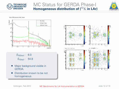
MC Status for GERDA Phase-IHomogeneous distribution of (42K in LAr)
E[MeV]0 0.5 1 1.5 2 2.5 3 3.5
cts
/10k
eV
1
10
210
310
410
510
Veto Efficiencies K42_hom
No Veto
10 keV Veto
100 keV Veto
Veto Efficiencies K42_hom
S100keV : 6.0
S10keV : 54.8
• Major background visible inGERDA.
• Distribution known to be nothomogeneous.
Göttingen, Feb 2012 MC Benchmarks for LAr Instrumentation in GERDA slide 12 of 15
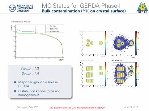
MC Status for GERDA Phase-IBulk contamination (42K on crystal surface)
E[MeV]0 0.5 1 1.5 2 2.5 3 3.5
cts
/10k
eV
1
10
210
310
410
510
610
Veto Efficiencies K42_surf
No Veto
10 keV Veto
100 keV Veto
Veto Efficiencies K42_surf
S100keV : 1.3
S10keV : 1.4
• Major background visible inGERDA.
• Distribution known to be nothomogeneous.
Göttingen, Feb 2012 MC Benchmarks for LAr Instrumentation in GERDA slide 13 of 15

Summary of results so far
Isotope Location Suppression factor100 keV 10 keV
280Tl Holders 254 354214Bi
Holders 3.5 4.4Crystal surface 13.8 20.1
42KHomogeneous in LAr 6.0 54.8
Surface of Crystal 1.3 1.460Co Homogeneously in Crystals 57 68210Po Surface of Crystal 2.1 2.2
• Values serve as an optimistic indicator of efficiency.
Göttingen, Feb 2012 MC Benchmarks for LAr Instrumentation in GERDA slide 14 of 15

Conclusion
• Currently MC for LAr veto designs is an ongoing project.
• MC being tuned using LArGe results as base.– Initial results are already promising.
• LAr veto instrumentation able to reduce background index by 2 orders ofmagnitude (on specific backgrounds).
– Limited efficiency on most visible GERDA background (42K).– Different approaches being followed in this case.
– Will become a key component to achieve the background index aimedfor phase II (10−3 counts/(kg·yr·keV)).
– Present background index : ∼ 10−2 counts/(kg·yr·keV).
• LAr veto geometries finishing implementation.
• Further validations with LArGe source measurements undergoing.
• More complex background studies under preparation.– Inhomogeneous distributions.
Göttingen, Feb 2012 MC Benchmarks for LAr Instrumentation in GERDA slide 15 of 15