
MBAND145400%3ALT14-16+SE+SEL+Bandsaw+Manual+rev+3.9.10 (1)
46
Laguna 14” Bandsaw
-
Upload
laguna-tools -
Category
Documents
-
view
224 -
download
0
description
Laguna 14” Bandsaw Read carefully before operating the Safety Rules As with all machinery there are, certain hazards involved with the operation and use. Using it with caution and respect will considerably lessen the possibility of personal injury. However, if normal safety precautions are overlooked or ignored, personal injury to the operator may result. If you have any questions relative to the installation and operation, do not use the equipment until you have contacted your supplying distributor.
Transcript of MBAND145400%3ALT14-16+SE+SEL+Bandsaw+Manual+rev+3.9.10 (1)

Laguna 14” Bandsaw
REV. 1 2
Safety Rules
As with all machinery there are, certain hazards involved with the operation and
use. Using it with caution and respect will considerably lessen the possibility of
personal injury. However, if normal safety precautions are overlooked or ignored,
personal injury to the operator may result. If you have any questions relative to
the installation and operation, do not use the equipment until you have contacted
your supplying distributor.
Read carefully before operating the 1. Keep working area clean, and be sure adequate lighting is available.
2. Do not wear loose clothing, gloves, bracelets, necklaces or ornaments.
Wear face, eye, ear, respiratory and body protection devices as indicated for
the operation or environment.
3. Be sure the power is disconnected from the machine before bandsaw is
serviced or an attachment is to be fitted or removed.
4. Never leave the machine with the power on.
5. Do not use a bent, dull, gummy or cracked cutting tool.
6. Be sure the keys and adjusting wrenches have been removed, and all nuts
and bolts are secured.
Warranty All of the Units are constructed under the strictest quality controls during
production and have undergone a final check before shipping. The guarantee is
valid for a period of 12 months from date of purchase and will be rendered null and
void in the case of unauthorized intervention, tampering or misuse other than
instructions specified in this manual.
IMPORTANT: Once fault has been verified, inform the seller (Laguna Tools) of the
problem or defect. Depending on the problem, the seller will ship a replacement
part or authorize the necessary repairs.

REV. 1 3
LT14 SEL Bandsaw MBAND145400 Blade length 103” to 105”.
Resaw capacity 8 5/8”.
Heavy duty dynamically balanced cast iron wheels.
Wheel dia 14” x 1 ¼”.
Wheel bearings sealed.
Miter gage slot 3/8” x ¾”.
Upper wheel tension and tilt system in solid steel and cast iron.
Solid upper guide post adjustable to be parallel to blade.
Recommended blades ¼” to ¾”.
Cast table size 15” x 15” with 4” steel extension (Total table size 19” x
15”).
Distance from column to blade 13 ¼”.
Table tilt from -15 to +45 degrees with flip positive stop at 90 degrees.
Double cast iron trunion.
Blade change from the side of the table.
Throat plate aluminum with 3 leveling screws.
Height from ground to table 44” with stand.
Height from base to table 24” without stand.
Base size 13 ½” x 24”.
Space age ceramic blade guide system both top and bottom.
Dust port at the side under the lower blade guide 3 1/8” dia.
Easy adjustable (for blade drift) rip Fence 16” long x 3” high and 1 5/8”.
1” solid steel fence rail.
Motor 1.5 HP 220V 1 Phase only.
Breaker size 15 amp.
Wire supplied 6’ long [No plug supplied].
If a longer wire is required use 12 swg.
Machine weight 230 lbs.
Options Miter gauge MBB35.00.08.00 5lbs
Stand MBB35.00.09.00 25lbs
REV. 1 4
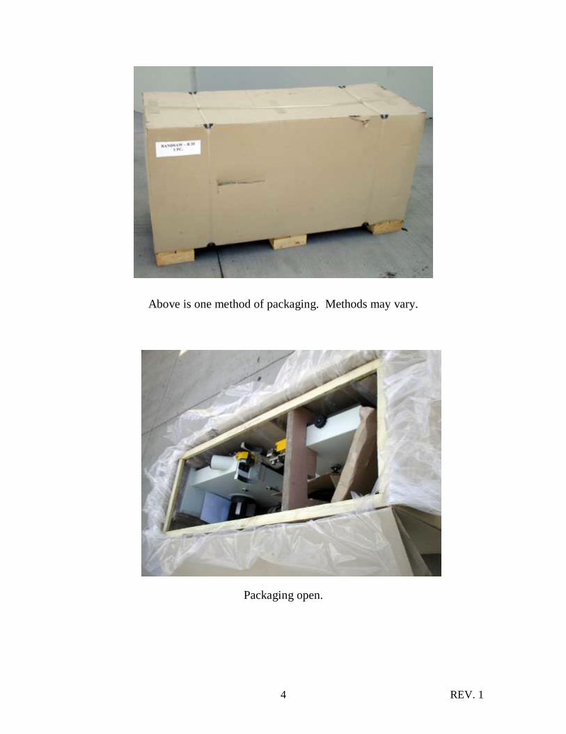
Above is one method of packaging. Methods may vary.
Packaging open.
REV. 1 5
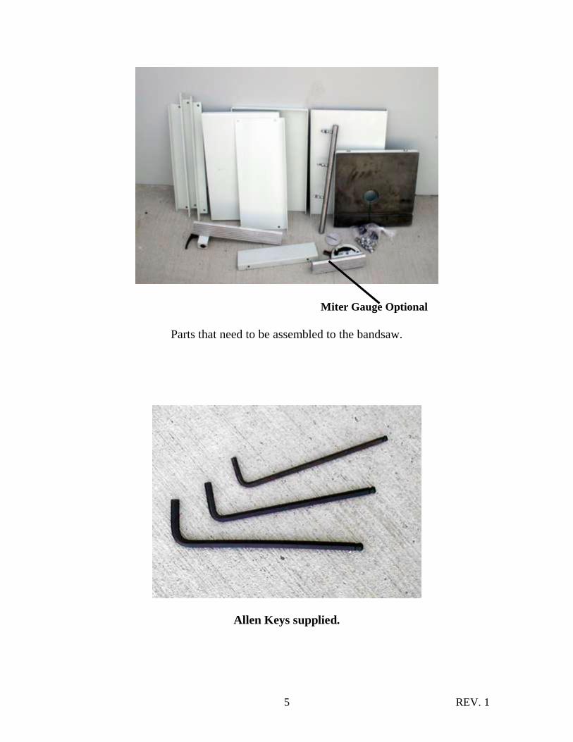
Miter Gauge Optional
Parts that need to be assembled to the bandsaw.
Allen Keys supplied.

REV. 1 6
Stand assembly Operation 1
NOTE: the angles may face in or out depending on your preference. Do not
tighten the bolts until the complete stand is assembled.
Finished assembled stand.
REV. 1 7
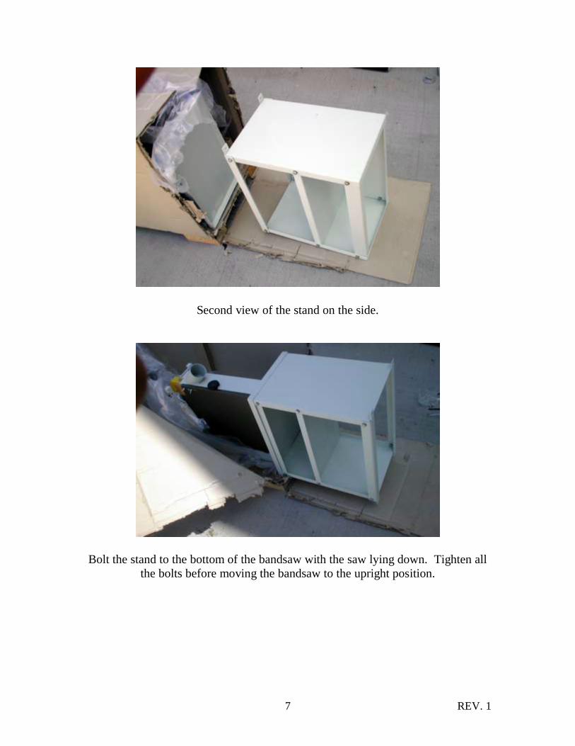
Second view of the stand on the side.
Bolt the stand to the bottom of the bandsaw with the saw lying down. Tighten all
the bolts before moving the bandsaw to the upright position.
REV. 1 8
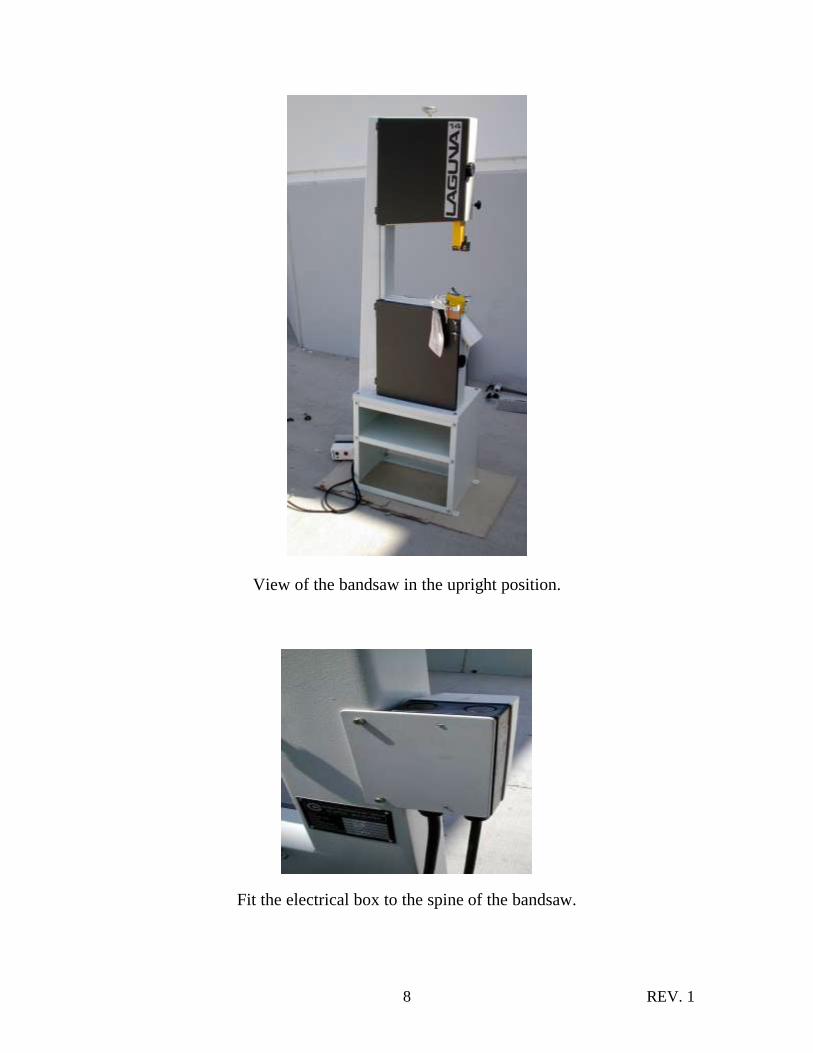
View of the bandsaw in the upright position.
Fit the electrical box to the spine of the bandsaw.
REV. 1 9
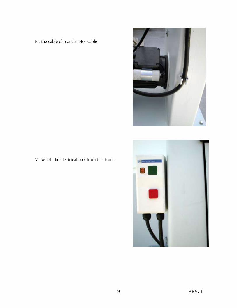
Fit the cable clip and motor cable
View of the electrical box from the front.

REV. 1 10
Remove the yellow guard, side blade guides and back blade guide. Remove
grease and re-assemble.
View with guard and grease removed
REV. 1 11
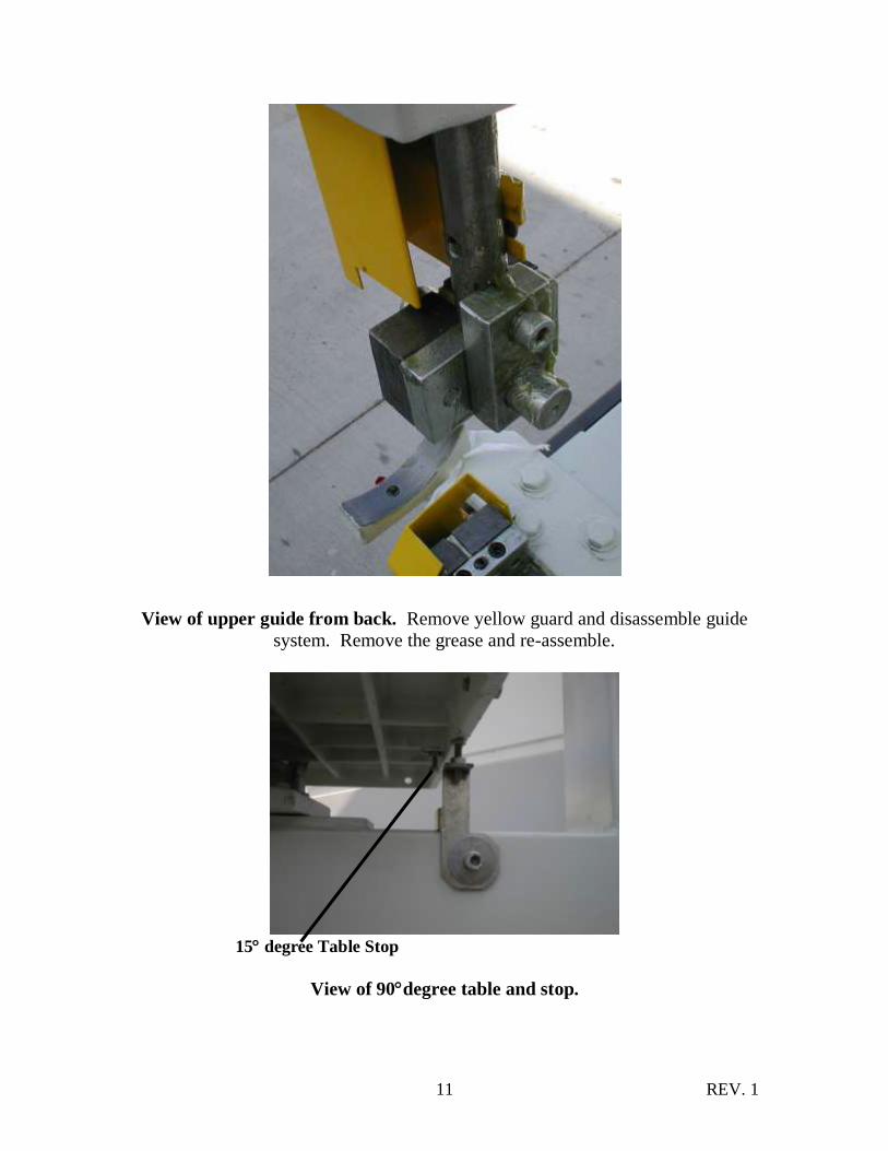
View of upper guide from back. Remove yellow guard and disassemble guide
system. Remove the grease and re-assemble.
15 degree Table Stop
View of 90degree table and stop.

REV. 1 12
90degree stop in down and table at -15 degrees.
View under table. Remove grease and pull the bolts through the slot. Lower the
table so that both bolts go through the holes in the trunion. Fit the washer and
clamp handle. You may find it of assistance, to make the table 90 degrees stop in
the up position.
REV. 1 13
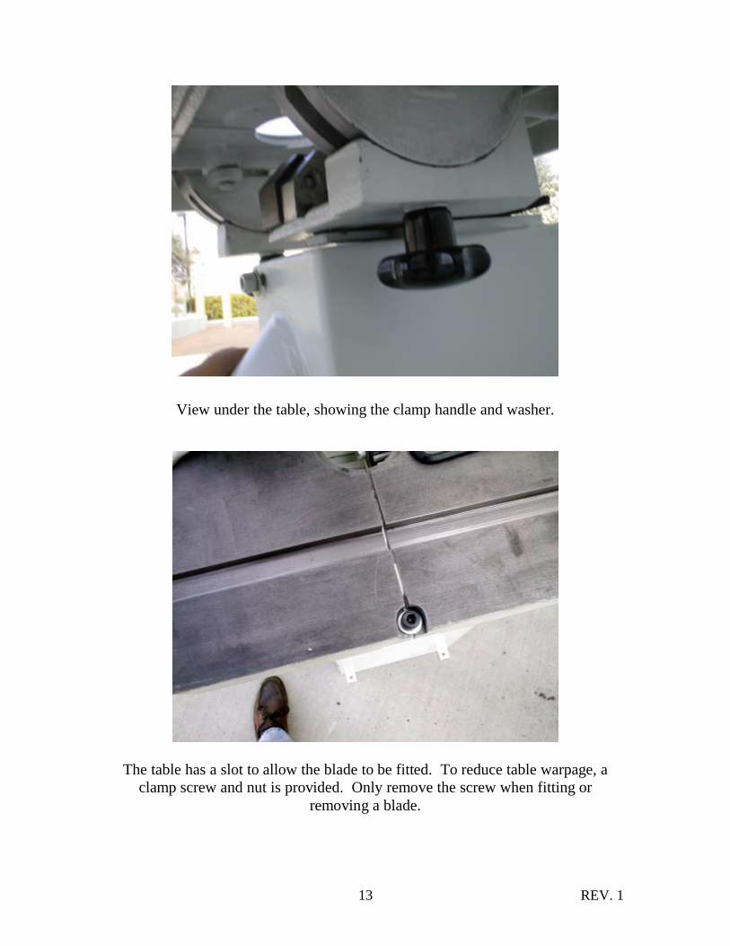
View under the table, showing the clamp handle and washer.
The table has a slot to allow the blade to be fitted. To reduce table warpage, a
clamp screw and nut is provided. Only remove the screw when fitting or
removing a blade.
REV. 1 14
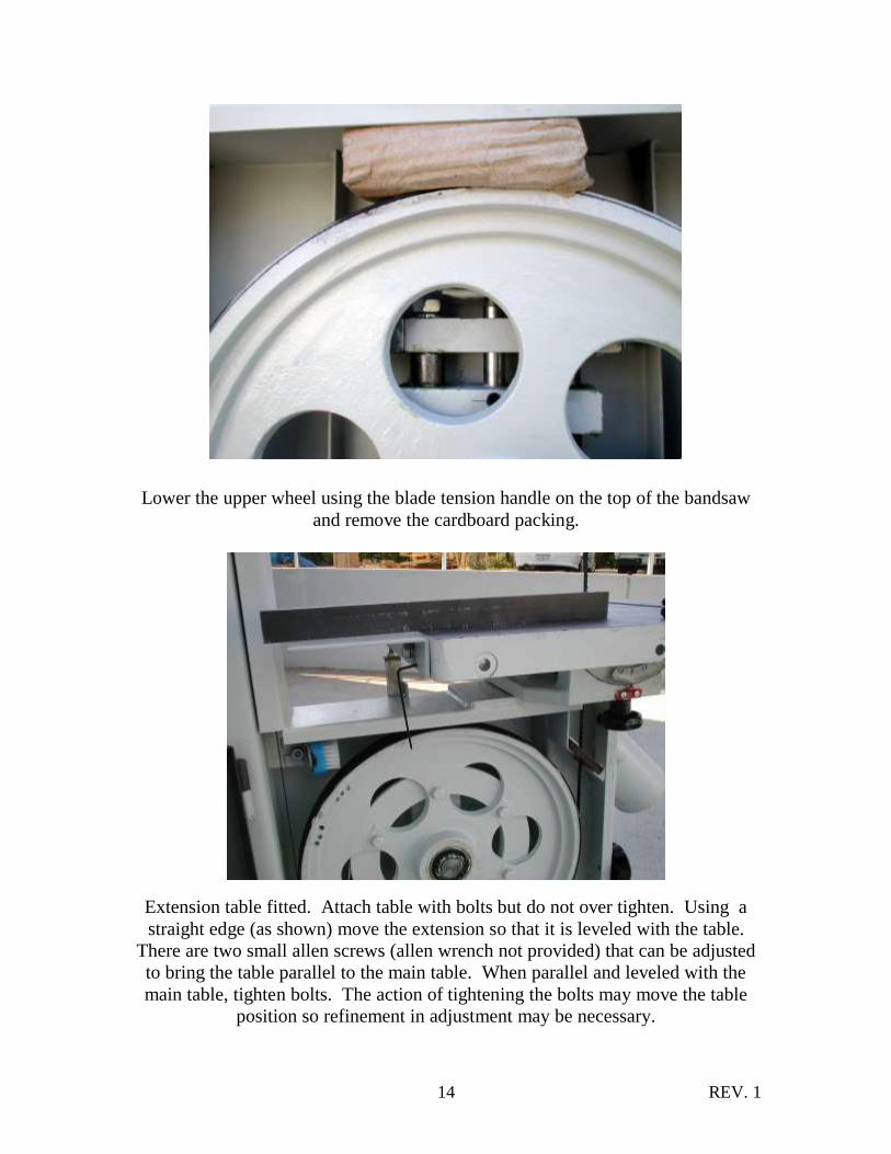
Lower the upper wheel using the blade tension handle on the top of the bandsaw
and remove the cardboard packing.
Extension table fitted. Attach table with bolts but do not over tighten. Using a
straight edge (as shown) move the extension so that it is leveled with the table.
There are two small allen screws (allen wrench not provided) that can be adjusted
to bring the table parallel to the main table. When parallel and leveled with the
main table, tighten bolts. The action of tightening the bolts may move the table
position so refinement in adjustment may be necessary.
REV. 1 15
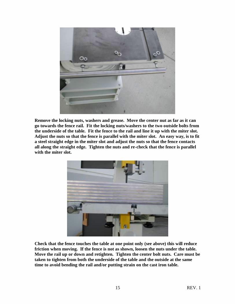
Remove the locking nuts, washers and grease. Move the center nut as far as it can
go towards the fence rail. Fit the locking nuts/washers to the two outside bolts from
the underside of the table. Fit the fence to the rail and line it up with the miter slot.
Adjust the nuts so that the fence is parallel with the miter slot. An easy way, is to fit
a steel straight edge in the miter slot and adjust the nuts so that the fence contacts
all along the straight edge. Tighten the nuts and re-check that the fence is parallel
with the miter slot.
Check that the fence touches the table at one point only (see above) this will reduce
friction when moving. If the fence is not as shown, loosen the nuts under the table.
Move the rail up or down and retighten. Tighten the center bolt nuts. Care must be
taken to tighten from both the underside of the table and the outside at the same
time to avoid bending the rail and/or putting strain on the cast iron table.
REV. 1 16
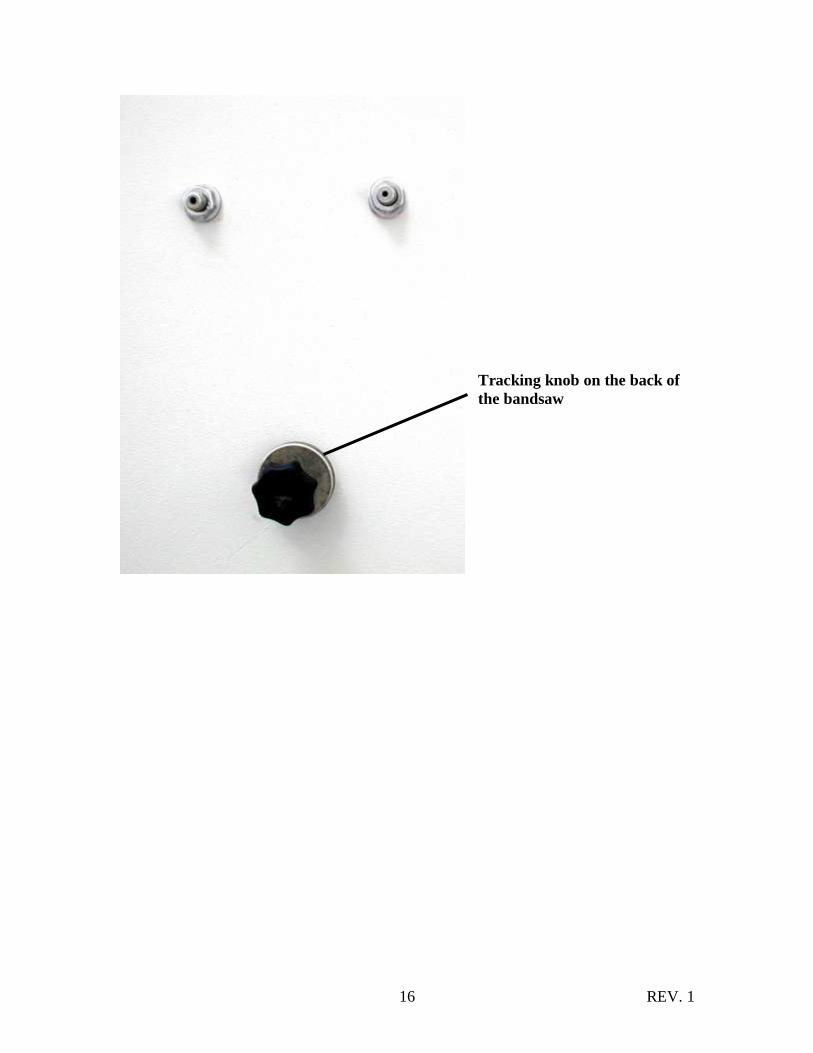
Tracking knob on the back of
the bandsaw

REV. 1 17
Introduction
Welcome to a new era in band sawing. You have purchased a bandsaw with a
revolutionary blade guide system (patent pending) that is designed to give you many
years of safe, high-quality band sawing.
Most blade guide systems are designed to support the blade on the sides and either above
or below the side guides to support the back of the blade. This can allow the blade to
twist as pressure from the wood being cut pushes against the back blade guide.
The surround guide eliminates this by supporting the blade above and below the back
blade guide, giving the blade unsurpassed stability. The surround guide also incorporates
patented ceramic as the blade support material. The advantage of this material is its
ability to resist wear and , with care, should give you years of safe service.
1. As with the roller guide systems, the Surround Guide System will damage your
bandsaw blade if it is not adjusted correctly. The guide blocks must not come in
contact with the blade teeth., it is advised that you run the blade by hand with the
guide blocks completely clear of the blade, and only when you are completely
sure that the blade is running consistently in the correct position, then adjust the
surround guide blocks as detailed in this manual.
2. When fitting a new blade to your bandsaw, adjust the guide blocks and run the
blade by hand through the guide blocks for at least two complete revolutions.
NOTE: the weld on the new blade may not be perfectly aligned and the
misalignment could hit the ceramic blocks (side and back), causing damage to the
blocks and/or the blade. If the blade has a bad weld, return it to your blade
supplier, or side dress and file the rear edge as needed.
3. The back blade guide is manufactured from ceramic, so as the blade is pushed
against it, friction between the blade and ceramic occurs. This action generates a
certain amount of sparks. This is normal and will reduce as the back blade guide
smoothes out the back of the blade.
4. The back blade guide will slowly form a small groove as the blade is used. It is
recommended that for approximately every 8 hours of use the guide be rotated
15 degrees. This will insure that the groove does not become too deep and will
greatly extend the life of the guide.
5. The Surround Guide System can be used on blades ¼” – ¾”.
REV. 1 18
6. The Surround Guide System uses ceramic to support and guide the blade. This
has many advantages, (very poor conductor of heat, very resistant to wear, etc.).
The disadvantage is that it is brittle, so the guides must never be dropped, exposed
to hard knocks or hit with hard objects. Any of the above actions may cause the
ceramic to chip or break and will detract from the performance of the surround
guide system. Any mistreatment of the guide system will render the warranty null
and void. The side guide blocks must be tightened before running the machine to
avoid jamming the blade and damaging the machine and/or guide blocks.
7. When cutting gummy or green wood, the blade can become covered with resin.
You will find that with the Surround Guide System the ceramic blocks remove the
resin as the blade is moved through the guide blocks and keep your blade clean
over that part of the blade. For this reason it is recommended that the blocks be
adjusted close to the teeth of the blade but must not contact them as the ceramic
will break or dull the teeth.
8. Be sure to release the blade tension when finished working or at night.
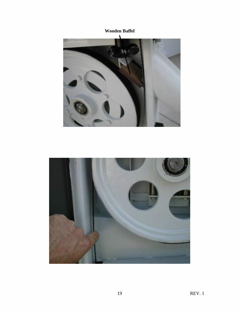
Blade Tensioning Procedure Remove the aluminum throat plate and wooden baffle. Move the upper and lower
blade guides back so that they are NOT in contact with the blade.
1. Install blade onto both tires.
a. If blade is narrower than ¾”, center blade on tires.
b. If blades are ¾” or wider, install with blade teeth hanging over the
tires.
2. Apply partial tension until blade stays on tires.
3. Look at upper wheel as thought it is a clock, at 9’O clock position, measure 3”
down on the blade. Apply pressure using (1) finger to deflect blade towards
frame of saw.
a. Narrow blades: (up to 3/8” ) Blade deflects ¼”
b. Medium blades: (1/2, ¾) Blade deflects 3/16”
After setting the tension, then adjust tracking to maintain position on wheel assy using
the tracking knob at the back of the bandsaw. Rotate wheels by hand before starting to
ensure blade tracking/tension are correct.
REV. 1 19
Wooden Baffel

REV. 1 20
View with the side guides removed. It is not necessary to remove the side
guides when adjusting the upper or lower guide. Loosen the allen screw at the
back (see next image) and adjust. To bring the back blade guide so that the blade
is centered, move the back blade guide forward so that it loosens the lock screw
(see image on page 20), it just touches the back of the blade. Tighten the lock
screw.

REV. 1 21
Loosen the lock screw and move the guide assembly so that the ceramic blocks are
positioned just behind the gullet of the blade. Nip the lock screw, unlock the guide shaft
and move it down so that the guide touches the table. Adjust the guide so that it is
parallel to the table. Move the guide shaft up and fully tighten the locking screw with the
allen wrench as shown above.
REV. 1 22
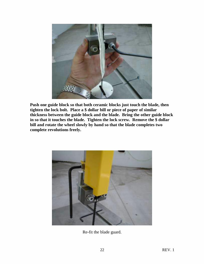
Push one guide block so that both ceramic blocks just touch the blade, then
tighten the lock bolt. Place a $ dollar bill or piece of paper of similar
thickness between the guide block and the blade. Bring the other guide block
in so that it touches the blade. Tighten the lock screw. Remove the $ dollar
bill and rotate the wheel slowly by hand so that the blade completes two
complete revolutions freely.
Re-fit the blade guard.
REV. 1 23
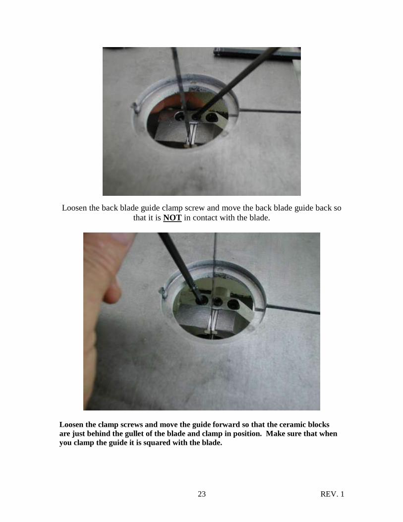
Loosen the back blade guide clamp screw and move the back blade guide back so
that it is NOT in contact with the blade.
Loosen the clamp screws and move the guide forward so that the ceramic blocks
are just behind the gullet of the blade and clamp in position. Make sure that when
you clamp the guide it is squared with the blade.

REV. 1 24
Loosen the back guide lock screw and move the back guide forward so that it just
touches the blade. Tighten the lock screw.
Move one side guide block so that both ceramic blocks just touch the blade, then
tighten the lock bolt.
REV. 1 25
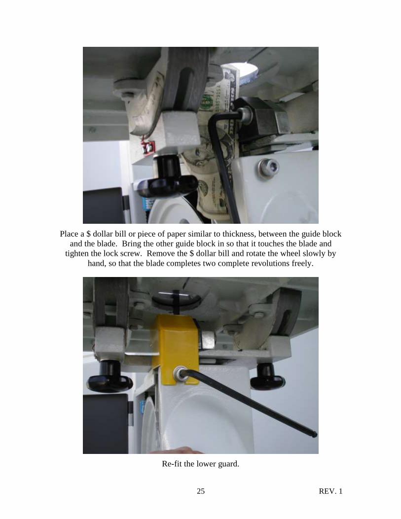
Place a $ dollar bill or piece of paper similar to thickness, between the guide block
and the blade. Bring the other guide block in so that it touches the blade and
tighten the lock screw. Remove the $ dollar bill and rotate the wheel slowly by
hand, so that the blade completes two complete revolutions freely.
Re-fit the lower guard.
REV. 1 26
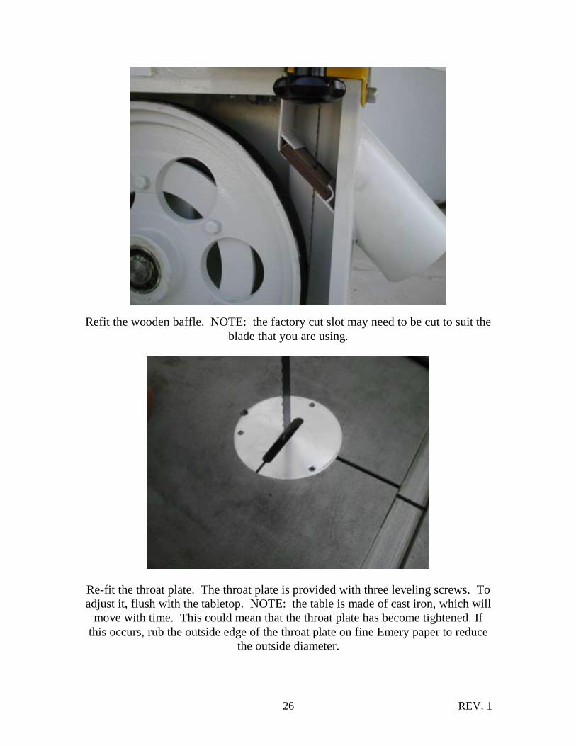
Refit the wooden baffle. NOTE: the factory cut slot may need to be cut to suit the
blade that you are using.
Re-fit the throat plate. The throat plate is provided with three leveling screws. To
adjust it, flush with the tabletop. NOTE: the table is made of cast iron, which will
move with time. This could mean that the throat plate has become tightened. If
this occurs, rub the outside edge of the throat plate on fine Emery paper to reduce
the outside diameter.

REV. 1 27
Refit the wooden baffle. NOTE: the factory cut slot may need to be cut to suit the
blade that you are using.
Re-fit the throat plate. The throat plate is provided with three leveling screws. To
adjust it, flush with the tabletop. NOTE: the table is made of cast iron, which will
move with time. This could mean that the throat plate has become tightened. If
this occurs, rub the outside edge of the throat plate on fine Emery paper to reduce
the outside diameter.

REV. 1 28
Adjust the brush so that it removes the sawdust off the lower wheel.
Drive belt adjustment screw.
REV. 1 29
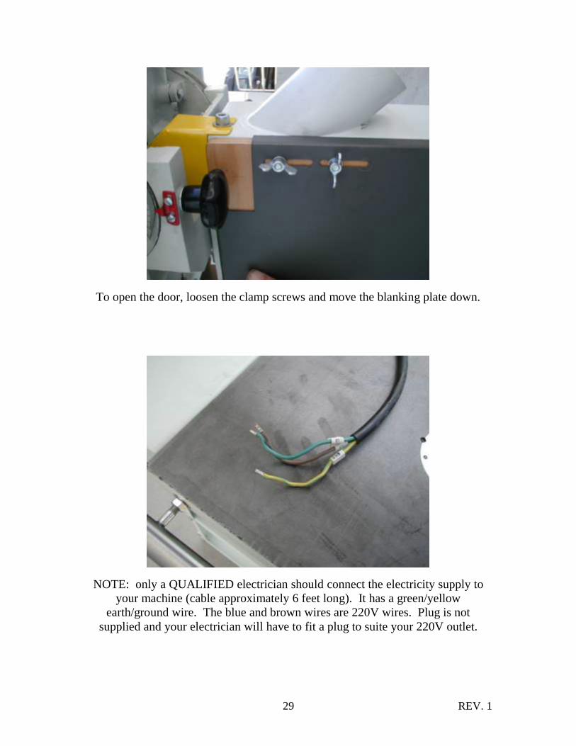
To open the door, loosen the clamp screws and move the blanking plate down.
NOTE: only a QUALIFIED electrician should connect the electricity supply to
your machine (cable approximately 6 feet long). It has a green/yellow
earth/ground wire. The blue and brown wires are 220V wires. Plug is not
supplied and your electrician will have to fit a plug to suite your 220V outlet.
REV. 1 30
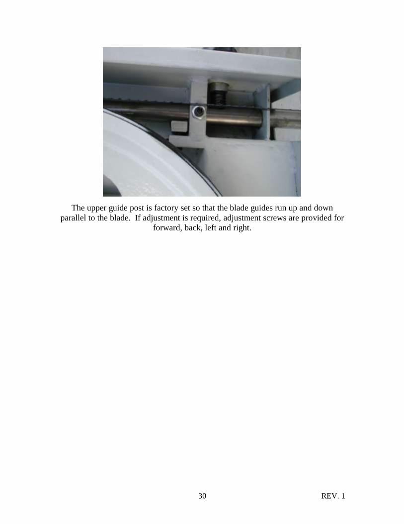
The upper guide post is factory set so that the blade guides run up and down
parallel to the blade. If adjustment is required, adjustment screws are provided for
forward, back, left and right.
REV. 1 31
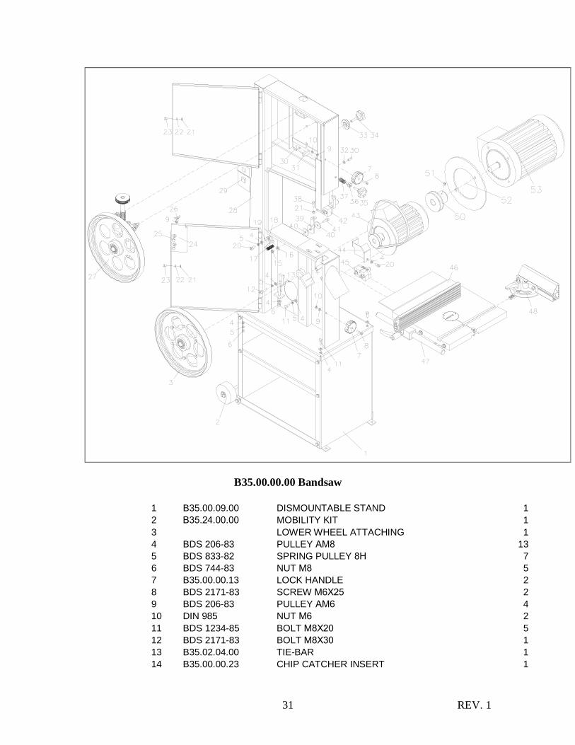
B35.00.00.00 Bandsaw
1 B35.00.09.00 DISMOUNTABLE STAND 1
2 В35.24.00.00 MOBILITY KIT 1
3 LOWER WHEEL ATTACHING 1
4 BDS 206-83 PULLEY АМ8 13
5 BDS 833-82 SPRING PULLEY 8Н 7
6 BDS 744-83 NUT М8 5
7 B35.00.00.13 LOCK HANDLE 2
8 BDS 2171-83 SCREW М6Х25 2
9 BDS 206-83 PULLEY АМ6 4
10 DIN 985 NUT М6 2
11 BDS 1234-85 BOLT М8Х20 5
12 BDS 2171-83 BOLT М8Х30 1
13 B35.02.04.00 TIE-BAR 1
14 B35.00.00.23 CHIP CATCHER INSERT 1

REV. 1 32
15 DIN 985 NUT М8 1
16 DIN 134 PULLEY Ф8,4ХФ18Х2 1
17 B35.02.00.10 BRUSH 1
18 B35.02.00.08 BRUSH CARRIER 1
19 DIN 7991 SCREW 2,9Х13 2
20 BDS 2171-83 SCREW М8Х16 2
21 BDS 744-83 NUT М6 3
22 BDS 833-82 SPRING PULLEY 6Н 2
23 BDS 1234-85 BOLT М6Х10 2
24 B35.00.00.19 CHPI CATCHER PROTECTING SCREEN 1
25 DIN 603 BOLT WITH SEMICIRCULAR HEAD М6Х20 2
26 BDS 1961-75 WING NUT М6 2
27 MECHANISM FOR TOP WHEEL STRETCHING 1
28 B35.06.00.00 BODY 1
29 LE-1-M35M716 STARTER 1
30 BDS 2171-83 SCREW М8Х20 4
31 B35.07.00.13 LIMITING STRAP 1
32 DIN 439 NUT М8 LOWER 2
33 B35.05.00.27 CLAMPING HANDLE 1
34 GN5337.2-40-M8-40 HANDLE 1
35 GN5337.2-40-M8-35 HANDLE 1
36 B35.07.00.11 SPECIAL NUT 1
37 ADM 410.20.00.106 SPRING 1
38 BDS 1234-85 BOLT М6Х25 1
39 B35.03.00.28 STOP AT 90º 1
40 UN 732 PULLEY Ф35ХФ9Х2,5 2
41 BDS 2171-83 SCREW М8Х25 1
42 LOWER BANDGUIDE 1
43 XZP V-SPAPED BELT L=862 1
44 B35.07.00.19 BAND GUARD – LOWER 1
45 BAND GUIDE – LOWER 1
46 TILTING TABLE 1
47 B35.00.01.00 BANDSAW FENCE 1
48 B35.00.08.00 MITER FENCE 1
50 B35.02.12.02 MOTOR WASHER 1
51 B35.02.00.11 COMPENSATE PULLEY 190Х111Х4 1
52 T80L-B14 F130 T80L-B14_F130 1
53 BDS 1362-83 SCREW М6Х10 1
REV. 1 33
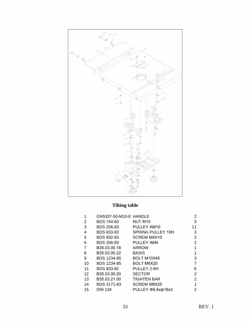
Tilting table
1 GN5337-50-M10-E HANDLE 2
2 BDS 744-83 NUT М10 3
3 BDS 206-83 PULLEY АМ10 11
4 BDS 833-82 SPRING PULLEY 10Н 3
5 BDS 832-83 SCREW М4Х10 2
6 BDS 206-83 PULLEY АМ4 2
7 В35.03.00.18 ARROW 1
8 В35.03.00.22 BASIS 1
9 BDS 1234-85 BOLT М10Х45 3
10 BDS 1234-85 BOLT М6Х20 7
11 BDS 833-82 PULLEY 2-6Н 6
12 В35.03.00.20 SECTOR 2
13 В35.03.21.00 TIGHTEN BAR 2
14 BDS 2171-83 SCREW М8Х25 1
15 DIN 134 PULLEY Ф8,4хф18х2 2
REV. 1 34
16 BDS 744-83 NUT М8 1
17 В35.03.00.05 TABLE 1
18 В35.03.00.01 INSERT 1
19 BDS 1361-83 STOP SCREW М4Х5 3
20 DIN 1481 SPRING PIN Ф5Х10 1
21 BDS 744-83 NUT М6 1
22 B35.03.00.27 TABLE EXTENSION 1
23 BDS 206-83 PULLEY АМ8 2
24 BDS 833-82 SPRING PULLEY 8Н 2
25 BDS 1234-85 BOLT М8Х16 2
26 DIN 913 SCREW М4Х5 2
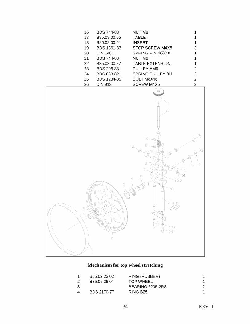
Mechanism for top wheel stretching
1 В35.02.22.02 RING (RUBBER) 1
2 В35.05.26.01 TOP WHEEL 1
3 BEARING 6205-2RS 2
4 BDS 2170-77 RING В25 1
REV. 1 35
5 BDS 2170-77 RING А52 1
6 В35.05.00.22 TOP AXIS 1
7 DIN 913 STOP SCREW М6Х10 1
8 В35.05.00.05 SQUARED AXIS 1
9 BDS 833-82 PULLEY 2-10Н 2
10 BDS 744-83 NUT М10 2
11 В35.05.12.00 SPECIAL HANDLE 1
12 В35.05.00.20 CARRYING STUD 1
14 BDS 206-83 PULLEY АМ12 4
15 DIN 439 LOWER NUT М12 4
16 В35.05.00.11 BOLT WITH EAR 2
17 DIN 985 NUT М10 2
19 В35.05.00.15 SLIDE BLOCK 1
20 DIN 913 STOP SCREW М8Х16 1
21 В35.05.00.06 GUIDE AXIS 2
22 В35.05.00.13 SQUARE L=100 1
23 BDS 833-82 PULLEY 2-8Н 2
24 BDS 2171-93 SCREW М8Х25 2
25 B35.05.00.18 SPRING 050018 1
25 B35.05.00.17 PULLEY Ф30ХФ12,5Х8 2
26 BDS 833-82 PULLEY АМ10 2
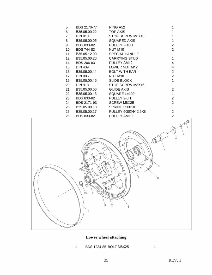
Lower wheel attaching
1 BDS 1234-85 BOLT М8Х25 1

REV. 1 36
2 BDS 833-82 PULLEY 2-8Н 7
3 В35.02.00.15 PULLEY_35Х9Х5 1
4 В35.02.00.18 LOWER AXIS 1
5 BEARING 6205-2RS 2
6 В35.02.12.03 BELT PULLEY 60 Hz 1
7 BDS 2170-77 RING А52 1
8 В35.02.22.01 LOWER WHEEL 1
9 BDS 1234-85 BOLT М8Х30 6
10 BDS 2170-77 RING В25 1
11 В35.02.22.02 RING (RUBBER) 1

REV. 1 37
Top band guide
2 BDS 2171-83 SCREW М8ХХ35 2
3 BDS 833-82 PULLEY АМ8 3
4 В35.07.23.00 BAND GUIDE BLOCK 2
5 DIN 913 SCREW М8Х10 2
6 В35.07.00.01 TOP STRAP 1

REV. 1 38
7 В35.07.00.04 CARRIER STRAP 1
8 В35.07.03.00 BAND TOP SUPPORT 1
9 BDS 2171-83 SCREW М8Х30 1
10 BDS 833-82 SPRING PULLEY 8Н 1
11 В35.07.00.07 CARRYING COLOMN 1
12 В35.07.15.00 BAND TOP GUARD 1
13 BDS 2171-83 SCREW М8Х16 1

REV. 1 39
Lower band guide
1 В35.07.25.00 LOWER BAND SUPPORT 1
2 DIN 913 SCREW М8Х10 1
3 BDS 2171-83 SCREW М6Х45 2
4 B35.07.23.00 BAND GUIDE BLOCK 1
5 BDS 206-83 PULLEY АМ8 2
6 BDS 2171-83 SCREW М8Х35 2
7 В35.07.21.00 BAND GUIDE BLOCK WITH CHAMFER 1
8 В35.07.00.24 LOWER STRAP 1
9 В35.07.00.20 STRAP 6Х20Х44 1

REV. 1 40
В35.00.01.00 Bandsaw fence
1 В35.00.01.01 BEAM 1
2 В35.00.01.09 SLIDE BLOCK 1
3 BDS 2171-83 SCREW М8Х25 2
4 BDS 833-82 PULLEY 2-8Н 2
5 GN603-63-M8-DGN HANDLE М8 1
6 В35.00.01.06 STUD М8Х35 1
7 BDS 1250-71 NUT М8 6
8 В35.00.01.02 STUD М8 3
9 BDS 206-83 PULLEY АМ8 6
10 B35.00.01.10 COTTER 15Х10Х78 1
11 В35.00.01.11 ALUMINUM PROFILE 1
REV. 1 41
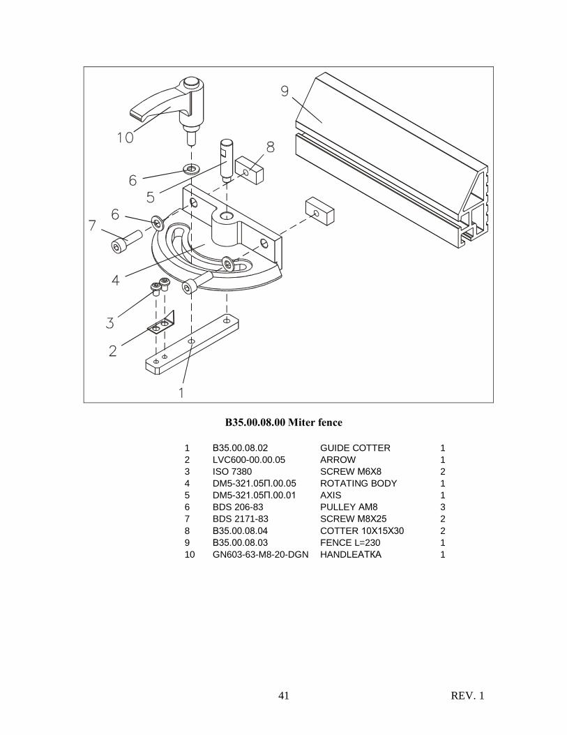
В35.00.08.00 Miter fence
1 В35.00.08.02 GUIDE COTTER 1
2 LVC600-00.00.05 ARROW 1
3 ISO 7380 SCREW М6Х8 2
4 DM5-321.05П.00.05 ROTATING BODY 1
5 DM5-321.05П.00.01 AXIS 1
6 BDS 206-83 PULLEY АМ8 3
7 BDS 2171-83 SCREW М8Х25 2
8 В35.00.08.04 COTTER 10Х15Х30 2
9 В35.00.08.03 FENCE L=230 1
10 GN603-63-M8-20-DGN HANDLEАТКА 1

REV. 1 42
В35.00.09.00 Stand
1 BDS 1234-84 BOLT М8Х20 12 2 BDS 206-83 PULLEY АМ8 24 3 B35.00.09.02 FUNDAMENTAL SQUARE 2 4 BDS 833-82 SPRING PULLEY 8Н 12 5 BDS 744-83 NUT М8 12 6 B35.00.09.03 RACK 1

REV. 1 43
7 B35.00.09.05 RIGHT SIDE PLATE 1 9 B35.00.09.01 FRONT WALL 1 10 B35.00.09.06 LEFT SIDE PLATE 1 11 B35.00.09.04 REAR WALL 1

REV. 1 44
В35.24.00.00 Mobility kit
1 DM.KH.00.02 ROLL 2
7 В35.24.01.00 CARRYING AXIS 1
2 BDS 206-83 PULLEY АМ12 2
3 BDS 55-77 SPLINT PIN 3,2Х20 2
5 BDS 206-83 PULLEY АМ8 4
6 BD 744-83 NUT М8 2
4 BDS 1234-85 BOLT М8Х35 2
REV. 1 45

REV. 1 46