Mazak Mazatrol Matrix Control Classroom Maintenance Manual C740MT0201E

ALARM LISTfor
MAZATROLFUSION 640M
MANUAL No. : H735SA0023E
Serial No. :
Before using this machine and equipment, fully understand the contents of thismanual to ensure proper operation. Should any questions arise, please ask thenearest Technical/Service Center.
1. Be sure to observe the safety precautions described in this manual and the contents of thesafety plates on the machine and equipment. Failure may cause serious personal injury ormaterial damage. Please replace any missing safety plates as soon as possible.
2. No modifications are to be performed that will affect operation safety. If such modifications arerequired, please contact the nearest Technical/Service Center.
3. For the purpose of explaining the operation of the machine and equipment, some illustrationsmay not include safety features such as covers, doors, etc. Before operation, make sure allsuch items are in place.
4. This manual was considered complete and accurate at the time of publication, however, due toour desire to constantly improve the quality and specification of all our products, it is subject tochange or modification. If you have any questions, please contact the nearest Technical/ServiceCenter.
5. Always keep this manual near the machinery for immediate use.
6. If a new manual is required, please order from the nearest Technical/Service Center with themanual No. or the machine name, serial No. and manual name.
Issued by Manual Publication Section, Yamazaki Mazak Corporation, Japan
10.1999
IMPORTANT NOTICE


SAFETY PRECAUTIONS
S-1
SAFETY PRECAUTIONS
Preface
Safety precautions relating to the CNC unit (in the remainder of this manual, referred to simply asthe NC unit) that is provided in this machine are explained below. Not only the persons whocreate programs, but also those who operate the machine must thoroughly understand thecontents of this manual to ensure safe operation of the machine.
Read all these safety precautions, even if your NC model does not have the correspondingfunctions or optional units and a part of the precautions do not apply.
Rule
1. This section contains the precautions to be observed as to the working methods and statesusually expected. Of course, however, unexpected operations and/or unexpected workingstates may take place at the user site.During daily operation of the machine, therefore, the user must pay extra careful attention toits own working safety as well as to observe the precautions described below.
2. The meanings of our safety precautions to DANGER, WARNING, and CAUTION are asfollows:
!DANGER
: Failure to follow these instructions could result in loss of life.
!WARNING
: Failure to observe these instructions could result in serious harm to a humanlife or body.
!CAUTION
: Failure to observe these instructions could result in minor injuries or seriousmachine damage.
HGENPA0022E

SAFETY PRECAUTIONS
S-2
Basics
!WARNING
� After turning power on, keep hands away from the keys, buttons, or switches of theoperating panel until an initial display has been made.
� Before proceeding to the next operations, fully check that correct data has been enteredand/or set. If the operator performs operations without being aware of data errors,unexpected operation of the machine will result.
� Before machining workpieces, perform operational tests and make sure that the machineoperates correctly. No workpieces must be machined without confirmation of normaloperation. Closely check the accuracy of programs by executing override, single-block, andother functions or by operating the machine at no load. Also, fully utilize tool path check,solid check, and other functions, if provided.
� Make sure that the appropriate feed rate and rotational speed are designated for theparticular machining requirements. Always understand that since the maximum usable feedrate and rotational speed are determined by the specifications of the tool to be used, thoseof the workpiece to be machined, and various other factors, actual capabilities differ fromthe machine specifications listed in this manual. If an inappropriate feed rate or rotationalspeed is designated, the workpiece or the tool may abruptly move out from the machine.
� Before executing correction functions, fully check that the direction and amount ofcorrection are correct. Unexpected operation of the machine will result if a correctionfunction is executed without its thorough understanding.
� Parameters are set to the optimum standard machining conditions prior to shipping of themachine from the factory. In principle, these settings should not be modified. If it becomesabsolutely necessary to modify the settings, perform modifications only after thoroughlyunderstanding the functions of the corresponding parameters. Modifications usually affectany program. Unexpected operation of the machine will result if the settings are modifiedwithout a thorough understanding.
Remarks on the cutting conditions recommended by the NC
!WARNING
� Before using the following cutting conditions:
- Cutting conditions that are the result of the MAZATROL Automatic Cutting ConditionsDetermination Function
- Cutting conditions suggested by the Machining Navigation Function
- Cutting conditions for tools that are suggested to be used by the Machining NavigationFunction
Confirm that every necessary precaution in regards to safe machine setup has been taken –especially for workpiece fixturing/clamping and tool setup.
� Confirm that the machine door is securely closed before starting machining.Failure to confirm safe machine setup may result in serious injury or death.

SAFETY PRECAUTIONS
S-3
Programming
!WARNING
� Fully check that the settings of the coordinate systems are correct. Even if the designatedprogram data is correct, errors in the system settings may cause the machine to operate inunexpected places and the workpiece to abruptly move out from the machine in the eventof contact with the tool.
� During surface velocity hold control, as the current workpiece coordinates of the surfacevelocity hold control axes approach zeroes, the spindle speed increases significantly. Forthe lathe, the workpiece may even come off if the chucking force decreases. Safety speedlimits must therefore be observed when designating spindle speeds.
� Even after inch/metric system selection, the units of the programs, tool information, orparameters that have been registered until that time are not converted. Fully check thesedata units before operating the machine. If the machine is operated without checks beingperformed, even existing correct programs may cause the machine to operate differentlyfrom the way it did before.
� If a program is executed that includes the absolute data commands and relative datacommands taken in the reverse of their original meaning, totally unexpected operation ofthe machine will result. Recheck the command scheme before executing programs.
� If an incorrect plane selection command is issued for a machine action such as arcinterpolation or fixed-cycle machining, the tool may collide with the workpiece or part of themachine since the motions of the control axes assumed and those of actual ones will beinterchanged. (This precaution applies only to NC units provided with EIA functions.)
� The mirror image, if made valid, changes subsequent machine actions significantly. Usethe mirror image function only after thoroughly understanding the above. (This precautionapplies only to NC units provided with EIA functions.)
� If machine coordinate system commands or reference position returning commands areissued with a correction function remaining made valid, correction may become invalidtemporarily. If this is not thoroughly understood, the machine may appear as if it wouldoperate against the expectations of the operator. Execute the above commands only aftermaking the corresponding correction function invalid. (This precaution applies only to NCunits provided with EIA functions.)
� The barrier function performs interference checks based on designated tool data. Enter thetool information that matches the tools to be actually used. Otherwise, the barrier functionwill not work correctly. (This precaution applies only to the M640T and M640MT.)
!CAUTION
� If axis-by-axis independent positioning is selected and simultaneously rapid feed selectedfor each axis, movements to the ending point will not usually become linear. Before usingthese functions, therefore, make sure that no obstructions are present on the path.

SAFETY PRECAUTIONS
S-4
Operations
!WARNING
� Single-block, feed hold, and override functions can be made invalid using system variables#3003 and #3004. Execution of this means the important modification that makes thecorresponding operations invalid. Before using these variables, therefore, give thoroughnotification to related persons. Also, the operator must check the settings of the systemvariables before starting the above operations.
� If manual intervention during automatic operation, machine locking, the mirror imagefunction, or other functions are executed, the workpiece coordinate systems will usually beshifted. When making machine restart after manual intervention, machine locking, themirror image function, or other functions, consider the resulting amounts of shift and takethe appropriate measures. If operation is restarted without any appropriate measures beingtaken, collision with the tool or workpiece may occur.
� Use the dry run function to check the machine for normal operation at no load. Since thefeed rate at this time becomes a dry run rate different from the program-designated feedrate, the axes may move at a feed rate higher than the programmed value.
� After operation has been stopped temporarily and insertion, deletion, updating, or othercommands executed for the active program, unexpected operation of the machine mayresult if that program is restarted. No such commands should, in principle, be issued for theactive program.
!CAUTION
� During manual operation, fully check the directions and speeds of axial movement.
� For a machine that requires manual homing, perform manual homing operations afterturning power on. Since the software-controlled stroke limits will remain ineffective untilmanual homing is completed, the machine will not stop even if it oversteps the limit area.As a result, serious machine damage will result.
� Do not designate an incorrect pulse multiplier when performing manual pulse handle feedoperations. If the multiplier is set to 100 times and the handle operated inadvertently, axialmovement will become faster than that expected.

OPERATIONAL WARRANTY FOR THE NC UNIT
S-5
OPERATIONAL WARRANTY FOR THE NC UNITThe warranty of the manufacturer does not cover any trouble arising if the NC unit is used for itsnon-intended purpose. Take notice of this when operating the unit.
Examples of the trouble arising if the NC unit is used for its non-intended purpose are listedbelow.
1. Trouble associated with and caused by the use of any commercially available softwareproducts (including user-created ones)
2. Trouble associated with and caused by the use of any Windows operating systems
3. Trouble associated with and caused by the use of any commercially available computerequipment

OPERATIONAL WARRANTY FOR THE NC UNIT
S-6
- NOTE -
E

C-1
CONTENTSPage
1 INTRODUCTION ................................................................................. 1-1
2 GENERAL OUTLINE ........................................................................... 2-1
2-1 Machine-Status Indicator Lamps ....................................................................... 2-1
2-2 Alarm Display..................................................................................................... 2-1
2-3 Color of Alarm Display and its Elimination ......................................................... 2-1
3 STRUCTURE OF THE ALARM LIST................................................... 3-1
4 PRECAUTIONS................................................................................... 4-1
5 ALARM LIST........................................................................................ 5-1

C-2
- NOTE -
E

INTRODUCTION 1
1-1
1 INTRODUCTION
This list describes the meaning of various alarms used for the MAZATROL FUSION 640M and the
procedure to eliminate their cause. For detailed description of the NC system MAZATROL
FUSION 640M, refer to the Operating Manual.
If an alarm message is displayed in the alarm display section of the screen, call the DIAGNOSIS
(ALARM) display to make sure of the type of the alarm.
Then refer to this Alarm List to locate and eliminate the cause of the alarm.
Read this Alarm List and the Operating Manual carefully in order to make the best use of the
possibilities of the MAZATROL FUSION 640M.
1 INTRODUCTION
1-2
- NOTE -
E

GENERAL OUTLINE 2
2-1
2 GENERAL OUTLINE
If machine failures occur or if erroneous operations are carried out, appropriate alarm numbers
and messages will be displayed in the alarm display section of the screen. If alarm display
appears, refer to the Alarm List to locate and eliminate the cause of the alarm. More than one
alarm may be raised at once, depending on the particular status of alarm occurring. In the
event of alarm display, therefore, it is highly recommended that the operator should call the
DIAGNOSIS (ALARM) display on the screen and make sure of the type of alarm.
2-1 Machine-Status Indicator Lamps
In the event of alarm, the machine-status indicator lamp ?ALARM on the operation panel will light
up.
2-2 Alarm Display
An alarm will be displayed on the DIAGNOSIS (ALARM) display in the following format:
650 CHAMFERING IMPOSSIBLE (1234, 56, 78)
For the DIAGNOSIS (ALARM) display, refer to Part 3 OPERATING NC UNIT AND
PREPARATION FOR AUTOMATIC OPERATION, 10-1 DIAGNOSIS (ALARM) Display of the
Operating Manual.
2-3 Color of Alarm Display and its Elimination
Alarm display is presented in either red or blue.
Display color Alarm elimination
Red Press the reset key.
Blue Press the clear key.
Tool sequence number or block number
Unit number or sequence number
Work number
Alarm message
Alarm number

2 GENERAL OUTLINE
2-2
- NOTE -
E

STRUCTURE OF THE ALARM LIST 3
3-1
3 STRUCTURE OF THE ALARM LIST
No. Message Type oferror
Stoppedstatus
Clearingprocedure
Display
[1] [2] Note 1 ( , , ) [3] [4] [5] Note 2
CauseCause of alarm
ActionAction to be taken to eliminate the cause.
Note 1: See 1 of 4. PRECAUTIONS below.
Note 2: See 2-3 Color of Alarm Display and its Elimination.
[1] Alarm number
[2] Alarm message
[3] Type of error
Code Type Description
A Operation A wrong key has been pressed. Or the machine has been operatedincorrectly.
B Registered data The program or tool data includes an error(s).
C Servo Malfunctioning of the servo control mechanism
D Spindle Malfunctioning of the spindle control mechanism
E NC equipment System (hardware/software) error
F Machine (PLC) Machine failure
G External I/O unit Malfunctioning of external I/O unit
[4] Stopped status
Status
H Emergency stop
I Reset stop
J Single-block stop
K Feed stop (hold)
L Operation continued
[5] Clearing procedure
Code Procedure
M Power off → Eliminate cause → Power back on
N Eliminate cause → Power off → Power back on
O Eliminate cause → Press reset key
P Press reset key
Q Eliminate cause → Press clear key
S Press clear key

3 STRUCTURE OF THE ALARM LIST
3-2
- NOTE -
E

PRECAUTIONS 4
4-1
4 PRECAUTIONS
1. If program-related alarm display appears, that portion of the program in which the alarm has
occurred will be displayed within the parentheses next to the alarm message. The meaning
of each code in parentheses on the Alarm List is listed in the table below.
Code Meaning
WNo. Work number (MAZATROL or EIA/ISO)
UNo. Unit number (MAZATROL)
SNo. Tool sequence number (MAZATROL)
NNo. Sequence number (EIA/ISO)
BNo. Block number (EIA/ISO)
blank No display, or intra-system alarm processing code
2. The stopped status ([4]), clearing procedure ([5]), and display color for some types of alarm
depend on whether the alarm-encountered program is on the foreground (program selected
on the POSITION display) or on the background (program selected on the PROGRAM
display). The above mentioned three types of information for the latter case are indicated
with parentheses in the Alarm List.
3. Alarms related to the mechanical and control systems use alarm code numbers from 200 to
399. For descriptions of the alarm code numbers from 200 to 399, refer to the Alarm List of
the Machine Operation Manual and the ELECTRIC WIRING DIAGRAM.

4 PRECAUTIONS
4-2
- NOTE -
E

ALARM LIST 5
5-1
5 ALARM LIST
No. MessageType of
errorStoppedstatus
Clearingprocedure
Display
001 EMERGENCY STOP ( , , )
Cause ——
Action ——
002 EMERGENCY STOP ( , , ) E H M Red
CauseTrouble has occurred in the hardware.
ActionTurn power off and then back on. If this does not clear the alarm status, please contact your YAMAZAKI MAZAK productsservice station.
003 EMERGENCY STOP ( , , ) A H M Red
CauseThe emergency stop button on the operation panel has been pressed.
ActionRelease the pressed state of the emergency stop button and reset the NC system to its initial state.
004 —— ( , , )
Cause ——
Action ——
005 SYSTEM SOFTWARE ERROR ( , , ) E H M Red
CauseThe contents of the system software and/or custom software have been destroyed.
ActionPlease contact your YAMAZAKI MAZAK products service station.
006 REMOTE I/O ERROR ( , , ) E H M Red
Cause
ActionPlease contact your YAMAZAKI MAZAK products service station.
007 SRAM MALFUNCTION ( , , ) E H M Red
CauseThe S-RAM mounted on the CPU card has become abnormal.
ActionPlease contact your YAMAZAKI MAZAK products service station.
008 RAM MALFUNCTION ( , , ) E H M Red
CauseThe RAM mounted on the CPU card has become abnormal.
ActionPlease contact your YAMAZAKI MAZAK products service station.
009 ABSOLUTE POSITION MALFUNCTION (Alarm No., axis, ) E H M Red
CauseThe absolute position detection system has lost absolute position data.
ActionPlease contact your YAMAZAKI MAZAK products service station.

5 ALARM LIST
5-2
No. Message Type oferror
Stoppedstatus
Clearingprocedure
Display
010 DETECTOR MALFUNCTION (Alarm No., axis, ) E H M Red
CauseThe absolute position detection system has detected its detector error(s).
ActionPlease contact your YAMAZAKI MAZAK products service station.
011 POSITION REFERENCE MALFUNCTION (Alarm No., axis, ) E H M Red
CauseThe absolute position detection system has detected an error(s) by cross-checking the absolute position of its detector andthe internal coordinate data of the NC system.
ActionPlease contact your YAMAZAKI MAZAK products service station.
012 ABSOLUTE POSITION WARNING (Alarm No., axis, ) E H M Red
CauseThe absolute position detection system has detected abnormal data.
ActionPlease contact your YAMAZAKI MAZAK products service station.
013 PRE-PROCESSOR MALFUNCTION ( , , ) E H M Red
CauseThe software is not correctly working.
ActionPlease contact your YAMAZAKI MAZAK products service station.
( , , )
Cause
Action
021 SYSTEM ERROR ( , , ) E H M Red
CauseThe software of the system has become abnormal.
ActionPlease contact your YAMAZAKI MAZAK products service station.
022 AMPLIFIER NOT EQUIPPED ( , , ) E H M Red
CauseAmplifier power is not yet turned on. Or no signals are transferred yet.
ActionCheck for an incorrectly connected cable, an incorrectly attached connector, an inadequate input supply voltage to theamplifier, an incorrect axis-number switch setting, etc.
( , , )
Cause
Action
031 SERVO MALFUNCTION 1 ( , , ) C H M Red
CauseThe servo (power-off level) is abnormal.
ActionPlease contact your YAMAZAKI MAZAK products service station.

ALARM LIST 5
5-3
No. Message Type oferror
Stoppedstatus
Clearingprocedure
Display
032 SERVO PARAMETER MALFUNCTION ( , , ) C H M Red
CauseThe parameters that have been transferred from the NC system to the servo amplifier during NC power-on are not correct.
ActionPlease contact your YAMAZAKI MAZAK products service station.
033 SERVO MALFUNCTION 2 ( , , ) C H M Red
CauseThe servo (NC reset level) is abnormal.
ActionPlease contact your YAMAZAKI MAZAK products service station.
034 SERVO MALFUNCTION 3 ( , , ) C H M Red
CauseThe servo (amplifier power-off level) is abnormal.
ActionPlease contact your YAMAZAKI MAZAK products service station.
( , , )
Cause
Action
041 SPINDLE MALFUNCTION 1 ( , , ) C H M Red
CauseThe spindle (power-off level) is abnormal.
ActionPlease contact your YAMAZAKI MAZAK products service station.
042 SPINDLE PARAMETER MALFUNCTION ( , , ) C H M Red
CauseThe parameters that have been transferred from the NC system to the spindle amplifier during NC power-on are not correct.
ActionPlease contact your YAMAZAKI MAZAK products service station.
043 SPINDLE MALFUNCTION 2 ( , , ) C H M Red
CauseThe spindle (NC reset level) is abnormal.
ActionPlease contact your YAMAZAKI MAZAK products service station.
044 SPINDLE MALFUNCTION 3 ( , , ) C H M Red
CauseThe spindle (amplifier power-off level) is abnormal.
ActionPlease contact your YAMAZAKI MAZAK products service station.
( , , )
Cause
Action

5 ALARM LIST
5-4
No. Message Type oferror
Stoppedstatus
Clearingprocedure
Display
051 E2ROM MALFUNCTION ( , , ) E L D Blue
CauseParameters cannot be correctly written into the E2ROM.
ActionPlease contact your YAMAZAKI MAZAK products service station.
052 BATTERY ALARM ( , , ) E L D Blue
CauseThe battery provided to retain parameters, machining programs and other types of data within the NC system has reachedthe minimum voltage level permissible or has run down.
ActionIt is required that the machining data is rechecked for possible loss or that the battery is recharged or replaced. For batteryrecharging or replacement, refer to the relevant description given in the Maintenance Manual.
053 NC TEMPERATURE WARNING ( , , ) E L Blue
CauseThe temperature of the control unit or operation board has increased above the required level.
ActionReduce the temperature by turning off the NC power or by mounting a cooling unit.
054 DIO5V MALFUNCTION ( , , ) E H O Blue
Cause
ActionPlease contact your YAMAZAKI MAZAK products service station.
055 DIO24V MALFUNCTION (Note, , ) E H O Blue
Cause
Action
Please contact your YAMAZAKI MAZAK products service station.
Note: & 00 00 01 00
7 6 5 4 3 2 1 0
The above example indicates that an communications error has occurred in station 1 of the No. 2 system.
056 SYSTEM SOFTWARE CHECKING ( , , ) H Red
CauseThe ROMs mounted in the system ROM card are currently being checked for abnormalities.
ActionWait for a while.
Please contact your YAMAZAKI MAZAK products service station if the alarm is not cleared.
( , , )
Cause
Action
No.1 system (X0~)No.2 system (X80~)No.3 system (X100~)No.4 system (X280~)
Station 1Station 2
Station 8
~

ALARM LIST 5
5-5
No. Message Type oferror
Stoppedstatus
Clearingprocedure
Display
066 PARAMETER MALFUNCTION ( , , ) E H O Blue
Cause
ActionPlease contact your YAMAZAKI MAZAK products service station.
( , , )
Cause
Action
071 ILLEGAL SERVO PARAMETER ( , , ) E H O Blue
Cause
ActionPlease contact your YAMAZAKI MAZAK products service station.
072 SERVO WARNING ( , , ) E H O Blue
Cause
ActionPlease contact your YAMAZAKI MAZAK products service station.
( , , )
Cause
Action
081 ILLEGAL SPINDLE PARAMETER ( , , ) E H O Blue
Cause
ActionPlease contact your YAMAZAKI MAZAK products service station.
082 SPINDLE WARNING ( , , ) E H O Blue
Cause
ActionPlease contact your YAMAZAKI MAZAK products service station.
( , , )
Cause
Action
5 ALARM LIST
5-6
No. Message Type oferror
Stoppedstatus
Clearingprocedure
Display
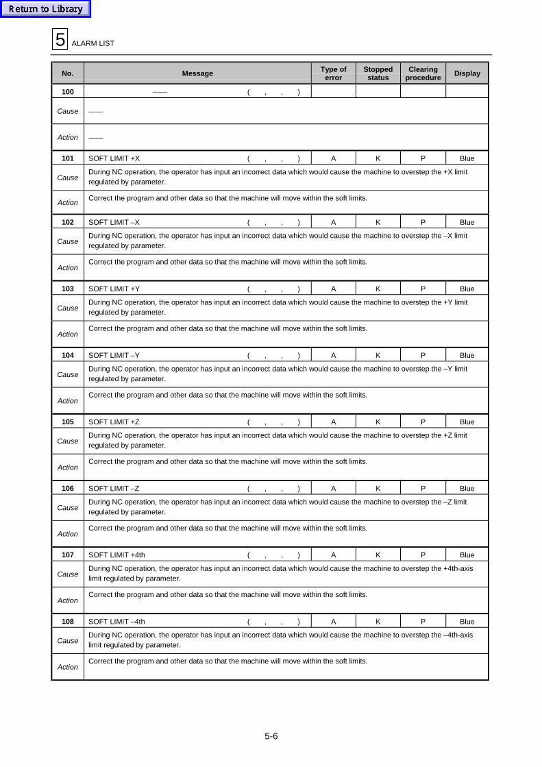
100 —— ( , , )
Cause ——
Action ——
101 SOFT LIMIT +X ( , , ) A K P Blue
CauseDuring NC operation, the operator has input an incorrect data which would cause the machine to overstep the +X limitregulated by parameter.
ActionCorrect the program and other data so that the machine will move within the soft limits.
102 SOFT LIMIT –X ( , , ) A K P Blue
CauseDuring NC operation, the operator has input an incorrect data which would cause the machine to overstep the –X limitregulated by parameter.
ActionCorrect the program and other data so that the machine will move within the soft limits.
103 SOFT LIMIT +Y ( , , ) A K P Blue
CauseDuring NC operation, the operator has input an incorrect data which would cause the machine to overstep the +Y limitregulated by parameter.
ActionCorrect the program and other data so that the machine will move within the soft limits.
104 SOFT LIMIT –Y ( , , ) A K P Blue
CauseDuring NC operation, the operator has input an incorrect data which would cause the machine to overstep the –Y limitregulated by parameter.
ActionCorrect the program and other data so that the machine will move within the soft limits.
105 SOFT LIMIT +Z ( , , ) A K P Blue
CauseDuring NC operation, the operator has input an incorrect data which would cause the machine to overstep the +Z limitregulated by parameter.
ActionCorrect the program and other data so that the machine will move within the soft limits.
106 SOFT LIMIT –Z ( , , ) A K P Blue
CauseDuring NC operation, the operator has input an incorrect data which would cause the machine to overstep the –Z limitregulated by parameter.
ActionCorrect the program and other data so that the machine will move within the soft limits.
107 SOFT LIMIT +4th ( , , ) A K P Blue
CauseDuring NC operation, the operator has input an incorrect data which would cause the machine to overstep the +4th-axislimit regulated by parameter.
ActionCorrect the program and other data so that the machine will move within the soft limits.
108 SOFT LIMIT –4th ( , , ) A K P Blue
CauseDuring NC operation, the operator has input an incorrect data which would cause the machine to overstep the –4th-axislimit regulated by parameter.
ActionCorrect the program and other data so that the machine will move within the soft limits.

ALARM LIST 5
5-7
No. Message Type oferror
Stoppedstatus
Clearingprocedure
Display
109 SOFT LIMIT +5th ( , , ) A K P Blue
CauseDuring NC operation, the operator has input an incorrect data which would cause the machine to overstep the +5th-axislimit regulated by parameter.
ActionCorrect the program and other data so that the machine will move within the soft limits.
110 SOFT LIMIT –5th ( , , ) A K P Blue
CauseDuring NC operation, the operator has input an incorrect data which would cause the machine to overstep the –5th-axislimit regulated by parameter.
ActionCorrect the program and other data so that the machine will move within the soft limits.
111 SOFT LIMIT +6th ( , , ) A K P Blue
CauseDuring NC operation, the operator has input an incorrect data which would cause the machine to overstep the +6th-axislimit regulated by parameter.
ActionCorrect the program and other data so that the machine will move within the soft limits.
112 SOFT LIMIT –6th ( , , ) A K P Blue
CauseDuring NC operation, the operator has input an incorrect data which would cause the machine to overstep the –6th-axislimit regulated by parameter.
ActionCorrect the program and other data so that the machine will move within the soft limits.
113 OVER TRAVEL +X ( , , ) A K P Red
CauseThe X-axis has reached its plus (+) stroke limit.
ActionMove the axis away from the end in manual operation mode.
114 OVER TRAVEL –X ( , , ) A K P Red
CauseThe X-axis has reached its minus (–) stroke limit.
ActionMove the axis away from the end in manual operation mode.
115 OVER TRAVEL +Y ( , , ) A K P Red
CauseThe Y-axis has reached its plus (+) stroke limit.
ActionMove the axis away from the end in manual operation mode.
116 OVER TRAVEL –Y ( , , ) A K P Red
CauseThe Y-axis has reached its minus (–) stroke limit.
ActionMove the axis away from the end in manual operation mode.
117 OVER TRAVEL +Z ( , , ) A K P Red
CauseThe Z-axis has reached its plus (+) stroke limit.
ActionMove the axis away from the end in manual operation mode.

5 ALARM LIST
5-8
No. Message Type oferror
Stoppedstatus
Clearingprocedure
Display
118 OVER TRAVEL –Z ( , , ) A K P Red
CauseThe Z-axis has reached its minus (–) stroke limit.
ActionMove the axis away from the end in manual operation mode.
119 OVER TRAVEL +4th ( , , ) A K P Red
CauseThe 4th-axis has reached its plus (+) stroke limit.
ActionMove the axis away from the end in manual operation mode.
120 OVER TRAVEL –4th ( , , ) A K P Red
CauseThe 4th-axis has reached its minus (–) stroke limit.
ActionMove the axis away from the end in manual operation mode.
121 OVER TRAVEL +5th ( , , ) A K P Red
CauseThe 5th-axis has reached its plus (+) stroke limit.
ActionMove the axis away from the end in manual operation mode.
122 OVER TRAVEL –5th ( , , ) A K P Red
CauseThe 5th-axis has reached its minus (–) stroke limit.
ActionMove the axis away from the end in manual operation mode.
123 OVER TRAVEL +6th ( , , ) A K P Red
CauseThe 6th-axis has reached its plus (+) stroke limit.
ActionMove the axis away from the end in manual operation mode.
124 OVER TRAVEL –6th ( , , ) A K P Red
CauseThe 6th-axis has reached its minus (–) stroke limit.
ActionMove the axis away from the end in manual operation mode.
125 ILLEGAL AXIS EXISTS ( , , ) E H O Red
CauseDuring reference-point return, the proximity-point detection limit switch has overrun the position in which the watchdog ismounted.
ActionEither extend the length of the proximity-point watchdog or reduce the reference-point returning speed. After that, carryout the zero-point returning operation once again.
126 Z AXIS NOT AT HOME ( , , ) E H O Red
CauseDuring initial reference-point return following the power-on action, an axis has not passed through the Z phase of thecorresponding detector.
ActionFirst actuate the handle for manual pulse feed to move the axis back in the opposite direction to the zero-point, and thencarry out the zero-point returning operation once again.

ALARM LIST 5
5-9
No. Message Type oferror
Stoppedstatus
Clearingprocedure
Display
127 ILLEGAL DIR. FOR ORIGIN RETURN ( , , ) A K P Red
CauseThe axis-movement direction selected with the axis selector button is not correct for the reference-point return in manualoperation mode.
ActionSet the correct direction using the axis selector buttons (+, –).
128 OUTSIDE INTERLOCK AXIS ( , , ) A K P Red
CauseAn axis is interlocked because the interlock function has become active (input signal has turned off).
ActionClear the active state of the interlock function.
129 INSIDE INTERLOCK AXIS ( , , ) A K P Red
CauseThe very direction in which the manual skip function has become effective is specified in the axis-movement command. Orthe servo-off function is active.
ActionDeactivate the servo-off function.
130 NO OPERATION MODE ( , , ) A K P Red
CauseThis message is displayed in the event of incorrect mode selection or a mode selector switch malfunction.
ActionIn the latter case, check the wiring of the mode selector switches.
131 CUTTING FEED OVERRIDE ZERO ( , , ) A K P Blue
CauseThe cutting-feed override value is set to 0 on the machine operation panel.
ActionChange the cutting-feed override value to one greater than 0. If this alarm message is displayed when the cutting-feedoverride value is not 0, check the signal line for a short-circuit.
132 FEEDRATE ZERO ( , , ) A K P Blue
CauseAn attempt has been made to execute dry-run in the automatic operation mode or in cutting feed mode, with the manualfeedrate remaining set to 0 on the machine operation panel.
ActionChange the manual feedrate to a value greater than 0. If this alarm message is displayed when the manual feedrate is not0, check the signal line for a short-circuit.
133 STOP SPINDLE ( , , ) D K N Red
CauseSpindle rotation did not start when the spindle rotation start command was issued during automatic operation.
ActionThe spindle amplifier and the encoder must be checked for normal operation. Please contact your YAMAZAKI MAZAKproducts service station.
134 SPINDLE ROTATION EXCEEDED ( , , ) D K N Red
CauseThe spindle-speed limit has been exceeded.
ActionReduce the spindle speed. The spindle amplifier must be checked for normal operation.
Please contact your YAMAZAKI MAZAK products service station.
135 BLOCK START INTERLOCK ( , , ) B K N Red
CauseThe interlock signal to lock the start of the program block has been input.
ActionThe sequence program needs checking for normal functioning.
Please contact your YAMAZAKI MAZAK products service station.

5 ALARM LIST
5-10
No. Message Type oferror
Stoppedstatus
Clearingprocedure
Display
136 CUTTING BLOCK START INTERLOCK ( , , ) B K N Red
CauseThe interlock signal to lock the start of the cutting program block has been input.
ActionThe sequence program needs checking for normal functioning.
Please contact your YAMAZAKI MAZAK products service station.
137 DYNAMIC COMPENSATION EXCEEDED ( , , ) A K P Red
CauseDynamic compensation amount exceeded 3 mm (0.12 in.).
ActionMake sure that the workpiece coordinate zero point is centrally positioned in the workpiece, and set the difference betweenthe center of the workpiece and the rotary center of the table to 3 mm (0.12 in.) or less.
138 CANNOT ROTATE TABLE ( , , ) A K P Red
CauseThere are areas where the table cannot be rotated.
ActionModify the approach point.
<HV>
139 —— ( , , )
Cause ——
Action ——
140 ILLEGAL REFERENCE RETURN No. ( , , ) A K P Blue
CauseReturning to the second reference point has been commanded in spite of the fact that returning to the first reference pointhas not yet occurred.
ActionReturn the axis to the first reference point first.
141 EXCESS SIMULTANEOUS ERROR ( , , ) A K P Blue
CauseThe synchronization error between the master axis and the slave axis during synchronous control has overstepped apredetermined allowable value.
ActionMove either axis in the direction that the error decreases.
Reduce the allowable value to zero (checking invalid), or increase the allowable value.
142 NONE OR DUPLICATE OPERAT. MODE ( , , ) A K P Blue
CauseAn operation mode has not been selected, or more than one operation mode have been selected.
The operation mode selector switch is malfunctioning.
ActionCheck for incorrect wiring of the input mode switch.
143 ILLEGAL HANDLE FEED AXIS ( , , ) A K P Blue
CauseAn inexistent axis has been designated as the handle feed axis.
Or a handle feed axis has not been designated.
ActionCheck the handle feed axis selection signal line for incorrect wiring.
Or check the maximum number of axes that can be used under the current specifications.
144 ILLEGAL CYCLE START ( , , ) A I O Red
Cause1. The cycle start button has been pressed during foreground program selection.
2. The cycle start button has been pressed during editing of a program on the EIA MONITOR display.
Action1. Select the work number of a foreground program before pressing the cycle start button.
2. Terminate the editing operations on the EIA MONITOR display before pressing the cycle start button.

ALARM LIST 5
5-11
No. Message Type oferror
Stoppedstatus
Clearingprocedure
Display
145 REQUIRE ABSOLUTE RECOVERY (Alarm No., , ) C K P Blue
CauseThe absolute position data has become lost.
Trouble has occurred in the absolute position detector.
ActionPlease contact your YAMAZAKI MAZAK products service station.
147 C AXIS TURNING ANGLE OVER (WNo.,NNo.,BNo.) E I (L) O Red
Cause1. The rotational angle limit at the shaping block connections has been exceeded.
2. The radius of the arc has decreased below the rotational radius of the C-axis.
Action1. Review the program.
2. Review the setting of parameter K1 (rotational radius of the C-axis).
Cause
Action
191 FILE SYSTEM I/O ERROR (WNo., UNo., SNo.) E L S Blue
CauseAn internal error(s) has occurred during program data change by the function of VFC, MMS etc.
ActionAfter checking the entire data of the program being executed, tool data, tool file, parameters, etc., save the data using thedata I/O operation (CMT) and then contact your YAMAZAKI MAZAK products service station.
192 EXECUTION IMPOSSIBLE (WNo., UNo., SNo.) E L S Blue
CauseAn internal error(s) has occurred during execution of the MMS unit.
ActionAfter checking the entire data of the program being executed, tool data, tool file, parameters, etc., save the data using thedata I/O operation (CMT) and then contact your YAMAZAKI MAZAK products service station.
193 NO TOOL IN MAGAZINE (WNo.,UNo., SNo.) B L S Blue
CauseTool data that correspond to the pocket numbers being displayed in the “TNo.” item of the POSITION display areunregistered.
ActionRegister the tool data.
194 NO TOOL DATA IN PROGRAM (WNo., UNo., SNo.) E L S Blue
CauseAn internal error(s) has occurred when circumferential speed or feedrate changing by VFC function was under way.
ActionAfter checking the entire data of the program being executed, tool data, tool file, parameters, etc., save the data using thedata I/O operation (CMT) and then contact your YAMAZAKI MAZAK products service station.
195 WRONG MEASURING DIRECTION ( , , ) A L P Red
CauseDuring the second or subsequent rounds of manual measurement, an attempt has been made to perform skipping in adirection not available for measurement.
ActionPerform measurements in the correct direction.
196 WRONG MEASURING POINT ( , , ) A L P Red
CauseDuring the second or subsequent rounds of manual measurement, an attempt has been made to measure an illegal point.
ActionMeasure correct points.

5 ALARM LIST
5-12
No. Message Type oferror
Stoppedstatus
Clearingprocedure
Display
197 UNREGISTERED HEAD DATA ( , , ) B L S Blue
CauseHead data of the head number being used during MMS or MDI MMS manual measurement does not exist.
ActionPlease contact your YAMAZAKI MAZAK products service station.
198 NO HEAD DATA ( , , ) B L S Blue
CauseHead data of the head number being used during MMS or MDI MMS manual measurement is partly missing.
ActionPlease contact your YAMAZAKI MAZAK products service station.
199 DIVISION BY ZERO ( , , ) K S Blue
CauseAn attempt has been made to carry out divisions by zero inside the NC system during measurement of the degree-of-straightness on the MEASURE display.
ActionCheck the touch sensor for abnormalities.
Carry out measurements once again if the touch sensor is normal.
( , , )
Cause
Action

ALARM LIST 5
5-13
No. Message Type oferror
Stoppedstatus
Clearingprocedure
Display
400 —— ( , , )
Cause ——
Action ——
401 ILLEGAL FORMAT ( , , ) A L S Blue
CauseThe format of the input data is not an available one.
Example: Negative data has been input to an item that rejects negative data input.
ActionPress the data cancellation key and then input correct data.
402 ILLEGAL NUMBER INPUT ( , , ) A L S Blue
Cause1. The work number of a display inhibiting program was specified.
2. The numeric value that has been input is out of the allowable range.
Action1. The operation concerned cannot be performed for the program of display inhibition (Program management function).
2. Press the clear key and then input correct data.
403 PROGRAM TOO LARGE ( , , ) A L S Blue
CauseThe limit of 250 lines per program has been exceeded.
ActionRecreate the program so that it consists of 250 lines or less.
404 MEMORY CAPACITY EXCEEDED ( , , ) A L S Blue
Cause
1. Additional creation of a machining program is no longer possible since the memory has already been filled up to itsmachining-program data storage capacity.
2. Additional preparation of process control data is no longer possible since 100 sets of such data have already beenstored.
3. Additional preparation of program layout data is no longer possible since 1000 sets of such data have already beenstored.
ActionMake an available storage area by either erasing an unnecessary machining program from the memory or saving amachining program onto an external storage, and then create a new machining program.
405 PROGRAM No. NOT FOUND ( , , ) A L S Blue
CauseAn attempt has been made to select a program whose work number has not been registered.
ActionSelect a program whose work number has been registered.
406 MEMORY PROTECT ( , , ) A L S Blue
Cause
1. Inhibiting operation (editing, erasing, renumber of work number and entry of names) has been performed for the edit-inhibiting program.
2. PROGRAM LOCK/ENABLE switch on the operation panel is set to the LOCK position.
3. An attempt has been made to carry out “TOOL NAME ORDER” operation while a tool remains set in the spindle.
Action
1. The operation concerned cannot be performed for the edit-inhibiting program (program management function).
2. Set the PROGRAM LOCK/ENABLE switch to the ENABLE position.
3. Remove the tool from the spindle, and then carry out the operation once again.
407 DESIGNATED DATA NOT FOUND ( , , ) A L S Blue
CauseThe number or character string that has been designated does not exist in the program.
ActionDesignate an existent number or character string.

5 ALARM LIST
5-14
No. Message Type oferror
Stoppedstatus
Clearingprocedure
Display
408 PROGRAM ERROR ( , , ) A L S Blue
CauseThe memory contents in the machining-program data storage area have been destroyed.
ActionDelete the corresponding program.
409 ILLEGAL INSERTION ( , , ) A L S Blue
CauseProgram data insertion is not possible.
ActionIt is not possible to insert data before the common program unit.
410 ILLEGAL DELETION ( , , ) A L S Blue
CauseProgram deletion is not possible.
- An attempt has been made to erase “%” during editing of the MAZATROL program.
ActionIt is not possible to delete the common unit.
- Edit the program only after moving the cursor to the position where the data exists.
411 POWER OFF DURING PROGRAM EDIT ( , , ) A L S Blue
CauseA portion of the program may have been destroyed because power has been turned off during program editing.
ActionCheck the corresponding program for incorrect data, and correct the program data if an error(s) exists in it.
412 SUB PROGRAM NESTING EXCEEDED ( , , ) A L S Blue
CauseThe number of repeats of subprogram nesting has exceeded nine times.
ActionCorrect the program so that the total number of repeats of subprogram nesting becomes nine or less.
413 MAX. No. OF REGIST PROG EXCEEDED ( , , ) A L S Blue
CauseThe program registration has exceeded its maximum value available (up to 960 programs).
ActionDelete an unnecessary program(s) from the memory, or save all the necessary programs onto an external storage and thendelete an unnecessary program.
414 AUTO CALCULATION IMPOSSIBLE (Note, , ) A L S Blue
Cause
Automatic calculation of circumferential speed and feedrate is not possible.
Note: The sub-error codes displayed when the NAVIGATE menu is selected on the MACHINING NAVIGATION–PREDICTION display are listed below.
–1: MAZATROL program file-opening error–2: MAZATROL program file-reading error–3: Tool materials mismatch error (when tool materials numbers are acquired)–4: Surface velocity auto-setting error–5: File-opening error relating to the basic coefficients of the workpiece materials upper-limit values–6: Workpiece materials mismatch error–7: File-opening error relating to surface velocity data tables–8: Tool materials mismatch error 2: Navigation file missing
ActionCheck and correct the tool sequence data or machining unit of the program.

ALARM LIST 5
5-15
No. Message Type oferror
Stoppedstatus
Clearingprocedure
Display
415 MIS-SET G CODE ( , , ) B L S Blue
CauseA G-code not covered by the specifications has been designated.
ActionCheck and correct the G-code addresses within the program.
416 AUTO PROCESS IMPOSSIBLE ( , , ) A L S Blue
CauseTools cannot be automatically developed because of errors of the machining-unit data.
ActionCheck and correct the machining-unit data.
417 EDITING PROHIBITED ( , , ) A L S Blue
CauseAn attempt has been made to modify a program whose editing is prohibited.
ActionModify the data only after cancelling the parameter setting of prohibition of editing.
418 EIA/ISO CONVERTING ( , , ) A L S Blue
CauseDuring EIA/ISO conversion, an attempt has been made to perform erasure, work number change or editing of theconversion source program. Or an attempt has been made to select the TOOL PATH CHECK display.
ActionDuring EIA/ISO conversion, erasure, work number change or editing of the conversion source program cannot be done.The TOOL PATH CHECK display cannot be selected.
419 AUTO TAP PROCESS IMPOSSIBLE ( , , ) A L S Blue
Cause
The pitch or other data cannot be automatically set because of incorrectness of the tap nominal diameter in the tapping-unitdata.Despite the fact that U.S.A. specifications-based pipe tap auto-setting is valid (D95 bit 0 = 1), the auto-setting functioncannot be executed since the auto-setting text file (Pipescdt. txt) is incorrect or contains no data.
ActionCheck and correct the tapping-unit data and tapping-tool sequence data of the program.Check and correct the auto-setting text file (Pipescdt. txt).
420 SAME DATA EXISTS ( , , ) A L S Blue
Cause
An attempt has been made to input the same data as that which has already been registered.
1. Pocket number in the TOOL LAYOUT display.
2. Machining-program number (changed)3. Machining priority number
ActionCheck and correct the data settings.
421 DATA NOT FOUND ( , , ) A L S Blue
CauseAn attempt has been made to designate the data that does not exist.
ActionCheck whether the designated data exists.
422 MEMORY PROTECT (I/O BUSY) ( , , ) A L S Blue
CauseAn attempt has been made to edit or input the machining program, tool data, etc. during I/O operation.
ActionWait until the I/O operation is completed, and then repeat the editing or input operation from the beginning.

5 ALARM LIST
5-16
No. Message Type oferror
Stoppedstatus
Clearingprocedure
Display
423 MAX NUMBER OF TOOLS EXCEEDED ( , , ) A L S Blue
CauseDuring tool layout, the number of tools used in the designated program has exceeded the maximum available number.
ActionCheck and correct the corresponding machining program so that the maximum available number of tools is not exceeded.
424 ALL POCKET NUMBERS NOT ASSIGNED ( , , ) A L S Blue
CauseIt is not possible to finish the tool layout operation because the pocket number has not yet been assigned to all the requiredtools.
ActionAssign the pocket number(s) and then finish the tool layout operation.
425 DATA MISSING ( , , ) A L S Blue
Cause
Processing is not possible because of lack of data.
1. Saving or loading has been attempted without designating any data (such as work numbers, etc.) on the DATA I/Odisplay.
2. The data to be input for restart operation is wanting.
ActionInput data correctly.
426 PROGRAM DATA MISSING ( , , ) A L S Blue
CauseThe tool sequence data cannot be automatically developed because of partial lack of the machining-unit data.
ActionFill up all the machining-unit data items with data.
427 MEMORY PROTECT (AUTO MODE) ( , , ) A L S Blue
CauseAn attempt has been made to input unallowable data in the automatic operation mode.
ActionChange the mode over to the manual mode, and then input the data.
428 MEMORY PROTECT (AUTO OPERATION) ( , , ) A L S Blue
CauseAn attempt has been made to input unallowable data on a display (such as the TOOL DATA display) during automaticoperation.
ActionInput allowable data only after placing the NC equipment in its reset state or after changing the current mode over toanother mode.
429 MEASURING NOT ALLOWED ( , , ) A L S Blue
Cause
The following conditions were not satisfied:
Coordinate measurement1. Automatic operation must not be in progress.2. The spindle must have a tool mounted on it.3. The tool data of the tool mounted on the spindle must have already been input.
Tool-length measurement1. Automatic operation must not be in progress.
Action Set the specified conditions and then make the measurement.
430 ILLEGAL TOOL DESIGNATED ( , , ) A L S Blue
CauseDuring creation of a machining program, an attempt has been made to input a tool name not available for the particularprogram unit, in the tool sequence.
ActionDesignate a correct tool name.

ALARM LIST 5
5-17
No. Message Type oferror
Stoppedstatus
Clearingprocedure
Display
431 ILLEGAL PALLET No. ( , , ) A L S Blue
CauseA nonexistent pallet number has been designated.
ActionDesignate a correct pallet number.
432 ILLEGAL TOOL No. ( , , ) A L S Blue
CauseA nonexistent tool number has been designated.
ActionDesignate a correct tool number.
433 SAME PROGRAM EXISTS ( , , ) A L S Blue
CauseThe number of the machining program that has been designated for program reading from an external unit already existswithin the NC memory.
ActionCheck the number of the machining program.
434 NO ASSIGNED TOOL IN TOOL FILE ( , , ) A L S Blue
CauseThe milling tools (face-mills, end-mills, chamfering cutters, and ball end-mills) that have been designated on the machiningprogram include a one(s) that is not yet registered in the TOOL FILE display.
ActionRegister the corresponding tools in the TOOL FILE display.
435 PROGRAM CHECK NOT ALLOWED ( , , )
CauseAn attempt has been made to restart on the TOOL PATH display during checking of the tool path.
ActionInterrupt the tool path checking operation before restarting.
436 UNREGISTERED TNo. ( , , ) A L S Blue
CauseAn unregistered tool number has been designated in the automatic tool-length measurement mode.
ActionDesignate a tool number registered in the TOOL DATA display.
437 NO NOM-φ DATA IN PROGRAM ( , , ) A L S Blue
CauseIt has been found during tool layout that there is a tool without a nominal diameter in the designated program.
ActionCheck if nominal diameters have been assigned to all tools registered in the designated program.
438 END UNIT NOT FOUND ( , , ) A L S Blue
CauseThe end unit is not included in the machining program.
ActionCreate the end unit at the end of the program.
439 MAZATROL PROGRAM DESIGNATED ( , , ) A L S Blue
Cause1. The machining program that has been designated for the tape punching machine is a MAZATROL program.
2. A MAZATROL program has been designated for copying purposes during EIA/ISO program editing.
ActionNo MAZATROL programs can be designated for tape punching machine or for copying purposes during EIA/ISO programediting.

5 ALARM LIST
5-18
No. Message Type oferror
Stoppedstatus
Clearingprocedure
Display
440 EIA/ISO PROGRAM DESIGNATED ( , , ) A L S Blue
Cause
1. The machining program that has been designated on the TOOL LAYOUT or PROCESS CONTROL display is anEIA/ISO program.
2. An EIA/ISO program has been designated for copying purposes during MAZATROL program editing.
3. An EIA/ISO program has been designated as the source program of EIA/ISO conversion.
4. An EIA/ISO program has been designated when writing coordinate values on the MEASURE display.
ActionNo EIA/ISO programs can be designated for operation on the TOOL LAYOUT ,PROCESS CONTROL or MEASUREdisplay or during EIA/ISO conversion or MAZATROL program editing.
441 UNREGISTERED HEAD DATA ( , , ) B L S Blue
CauseThe head number that has been designated during MDI-MMS setting does not exist in the head data.
ActionReview the designated head number.
442 DATA RENEWAL NOT ALLOWED ( , , ) A L S Blue
CauseNo updates can be made to the machining program.
ActionThis message may also be displayed when the NC equipment is busy processing data. Press the clear key and then carryout the operation once again.
443 HELP IS NOT AVAILABLE ( , , ) A L S Blue
CauseNo help display is prepared for items other than machining units.
ActionMove the cursor to a machining unit line to get a help display.
444 EDITING PROHIBITED AREA ( , , ) A L S Blue
CauseDuring automatic operation based on the EIA MONITOR display, an attempt has been made to move the cursor to theprogram section whose editing was prohibited.
ActionThe cursor cannot be moved to the area where editing is prohibited.
445 ILLEGAL UNIT ( , , ) B L S Blue
CauseAn attempt has been made to set tool layout data in a MAZATROL program containing an illegal unit(s).
ActionReview the program.
446 RESTART TIMES EXCEEDED ( , , ) A L S Blue
CauseThe block to be searched for at the time of restart of the EIA/ISO program does exist, but the designated number of times ofreappearance of the block is too large.
ActionCheck the number of times of reappearance of the block.
447 PROGRAM ERROR ( , , ) A L S Blue
CauseA program error(s) has occurred during EIA/ISO restart search.
ActionThe program being searched for includes an error(s). Perform a tool-path check upon the program contents.

ALARM LIST 5
5-19
No. Message Type oferror
Stoppedstatus
Clearingprocedure
Display
448 RESTART SEARCH UNFINISHED ( , , )
CauseEIA/ISO restart searching has not been executed.
ActionDesignate the restart position and press the EIA/ISO SEARCH to search the intended restart position.
449 RESTART SEARCH FINISHED ( , , ) A L S Blue
CauseAn attempt has been made to carry out another search operation when EIA/ISO restart searching had already beenfinished.
ActionPress the reset key and then carry out the restart operation once again.
450 TOUCH SENSOR NOT IN SPINDLE ( , , ) A L S Blue
CauseThe spindle did not have a mounted touch sensor when an attempt was made to set MAZATROL coordinate measurementdata on the PROGRAM display (MAZATROL).
ActionMount a touch sensor in the spindle before setting the data.
451 SAME MATERIAL ENTERED ( , , ) B L S Blue
CauseThe materials name that has been designated on the CUTTING CONDITION (MATERIAL) display already exists.
ActionDesignate a new materials name.
452 NO SHAPE DATA IN UNIT ( , , ) A L S Blue
CauseNo shape data exists in the program unit that has been designated in an attempt to make a copy of shape data.
ActionCheck the contents of the program unit for which shape copying is to be made.
453 NO SHAPE DATA TO COPY IN UNIT ( , , ) A L S Blue
CauseAn attempt has been made to copy shape data whose type is not available for the particular program unit.
ActionIt is not possible to copy shape data of the pallet-changing unit, index unit, or other units that do not have a shapesequence.
454 CURSOR POSITION INCORRECT ( , , ) A L S Blue
Cause
Processing not permissible for the current cursor position has been attempted.
Example 1: An attempt has been made to carry out a shape copying operation with the cursor on the tool sequence line.
Example 2: The SHAPE CHECK display has been selected on a shape sequence line not actually executed duringautomatic operation.
ActionExample 1: No shape data can be copied on the tool sequence line.
Example 2: Review the program.
455 SAME PROGRAM No. DESIGNATED ( , , ) A L S Blue
CauseThe machining program currently being edited has been appointed for the particular program copying operation.
ActionCopying within the same program is not possible. Check the designated program number.
456 NO TOOL IN SPINDLE ( , , ) A L S Blue
CauseThe spindle does not currently have a tool mounted on it.
ActionAfter mounting a tool on the spindle, carry out the particular operation once again.

5 ALARM LIST
5-20
No. Message Type oferror
Stoppedstatus
Clearingprocedure
Display
457 DATA ADDRESS NOT FOUND ( , , ) A L S Blue
CauseDuring creation of manual program mode unit, data setting has been attempted without addressing.
ActionDuring creation of the manual program mode unit, designate an address before setting data.
458 INTERFERING TOOL REGISTERED ( , , )
Cause
An attempt has been made to register a tool most likely to interfere with an adjacent pocket.
Example 1: An attempt has been made to register tool data or tool change data on the TOOL DATA display.
Example 2: An attempt has been made to set such a tool on the TOOL LAYOUT display that is likely to interfere with anadjacent pocket.
ActionSelect a pocket that does not cause interference with an adjacent one.
459 DISPLAY PROTECT ( , , ) A L S Blue
CauseAn attempt has been made to display a program whose display is prohibited.
ActionDisplay the program only after cancelling the parameter setting of prohibition of display.
460 PRINTER IN OPERATION ( , , ) A L S Blue
CauseAn attempt was made to print out the data by using of the DATA I/O display (PRINTER) while the hard copy is being made.An attempt was made on the TRACE display to perform display scaling change, material shape and tool path drawing whilethe hard copy is being made.
ActionAfter finishing the hard copy, carry out the operations.
461 PRIORITY No. OVERLAP (WNo., UNo., SNo.) A L S Blue
CauseThe same priority number is assigned to different tools.
ActionWithin one process, the same priority number must not be assigned to different tools.Change the priority number.
462 ILLEGAL PRIORITY NUMBER (WNo., UNo., SNo.) A L S Blue
CauseThe priority numbering order within a unit is not correct.
ActionThe machining order within one unit has been reversed by the incorrect priority numbering.Change the priority numbers.
463 PRIORITY No. OVERFLOW ( , , ) A L S Blue
CauseA priority number exceeding 99 has occurred because an attempt has been made to move a priority number(s) on thePROGRAM LAYOUT display.
ActionSet priority numbers in the correct order, and then move the desired priority number(s).
464 ILLEGAL ADDRESS INPUT ( , , ) A L S Blue
CauseAn address not covered by the specifications has been designated during input of subprogram unit addresses on thePROGRAM display (MAZATROL).
ActionCheck and correct the address.
Check the specifications.

ALARM LIST 5
5-21
No. Message Type oferror
Stoppedstatus
Clearingprocedure
Display
465 EIA SHAPE DATA NOT FOUND ( , , ) A L S Blue
CauseAlthough an attempt has been made to draw a workpiece shape using the selected EIA/ISO program, shape data is notpresent in that program.
Action
Recheck the program.
If the program is that which has been obtained by EIA/ISO conversion output, change the setting of the bit 0 of parameterF89 to 1 and then carry out the converting operation once again.
466 INCORRECT EIA SHAPE DATA ( , , ) A L S Blue
CauseAlthough an attempt has been made to draw a workpiece shape using the selected EIA/ISO program, the correspondingshape data is not correct.
ActionReview the program.
467 —— ( , , )
Cause ——
Action ——
468 MAINTENANCE CHECK WARNING ( , , ) L S Blue
CauseThe target time of the items which had been set on the MAINTENANCE CHECK display has been exceeded.
ActionCarry out periodic checks, and then after completion of the checks, reset the target time of the check items of theMAINTENANCE CHECK display to zero (0).
469 TPC DATA EDIT IMPOSSIBLE ( , , ) A L S Blue
CauseThe TPC data setting is not possible for the designated unit.
ActionCheck the program.
470 ILLEGAL TPC DATA ( , , ) B L S Blue
CauseThe TPC data for the unit is not correct.
After setting the TPC data, the unit machining mode has been changed.
ActionDelete the TPC data and set correct TPC data once again whenever required.
471 TPC DATA NOT FOUND ( , , ) A L S Blue
CauseWhile the cursor was on a line of unit not containing TPC data on the display, the TPC menu key was pressed during theprogram list mode.
ActionPress the TPC menu key after shifting to the programming mode.
472 CALCULATION ERROR ( , , ) B L S Blue
CauseThe calculation expressions displayed in the desk calculator window includes expressions that result in a calculation failure.
ActionReview the calculation expressions, and correct nonexecutable sections, such as those which may include division by 0 orresult in a negative number in SQRT.
473 —— ( , , )
Cause ——
Action ——

5 ALARM LIST
5-22
No. Message Type oferror
Stoppedstatus
Clearingprocedure
Display
474 NO PROGRAM DISPLAY (TAPE MODE) ( , , ) A L S Blue
Cause
1. During tape operation mode, an attempt has been made to select the EIA MONITOR display or to open the EIAmonitor window.
2. An attempt has been made to change the operation mode to tape operation mode when the EIA MONITOR display is
selected or the EIA monitor window is opened.
Action
1. During tape operation mode, programs cannot be displayed on the EIA MONITOR display or in the EIA monitor
window.
2. Select other than the EIA MONITOR display or close the EIA monitor window before changing the operation mode totape operation mode.
475 NO EIA/ISO OPTION ( , , ) A L S Blue
CauseAn attempt has been made to use an EIA/ISO-option related function in spite of the absence of an EIA/ISO option.
ActionAn EIA/ISO-option related function cannot be used since the system has no EIA/ISO option.
476 NO OPTION ( , , ) A L S Blue
CauseAn attempt has been made to use an optional function in spite of the absence of that option.
ActionThis function cannot be used since the system does not have the option for the function.
477 SOLID DESCRIPTION IMPOSSIBLE (STS, , )
STS Cause1 Memory insufficient2 Calculation impossible
Cause
3 Necessary data not setSTS Action
1 Divide the program.
2 Check the parameter.Action
3 Check the setting range of the tool data.
478 MEMORY PROTECT (MEASURING) ( , , ) A L S Blue
CauseAn attempt has been made to copy the coordinates data in WRITE DATA column of the MEASURE display into thedesignated position, while measurement using the MEASURE display is in progress.
ActionCopy the coodinates data only after the measurement has been completed.
( , , )
Cause
Action
497 HEAD ANGLE INCORRECT ( , , ) A L S Blue
Cause
1. An attempt has been made to strage the tool tip position with the head not in its horizontal machining position (TOOLDATE or TOOL OFFSET display only).
2. An attempt has been made to perform MDI-MMS operation with the head not in its horizontal or vertical machiningposition.
Action
1. Tool tip position strage (tool length measurement) is possible only with the head in its horizontal machining position.
2. MDI-MMS is possible only with the head in its horizontal or vertical machining position.
<HV>
498 NO HEAD DATA ( , , ) A L S Blue
CauseOffset data for the selected head is not registered on the HEAD OFFSET display.
ActionCheck if the selected head data is registered on the HEAD OFFSET display.

ALARM LIST 5
5-23
No. Message Type oferror
Stoppedstatus
Clearingprocedure
Display
499 ILLEGAL HEAD TYPE ( , , ) A L S Blue
CauseAn attempt has been made to perform tool tip position storage for on the TOOL DATE or TOOL OFFSET display during useof the horizontal type of head.
ActionTo perform tool tip position storage for tool length measurement, mount a vertical head or a cover.

5 ALARM LIST
5-24
No. Message Type oferror
Stoppedstatus
Clearingprocedure
Display
500 —— ( , , )
Cause ——
Action ——
501 ILLEGAL FORMAT ( , , ) A L S Blue
CauseA cassette tape or floppy disk that contains data other than M640M or M PLUS data has been set.
ActionSet the cassette tape or floppy disk that contains M640M or M PLUS data.
502 CANNOT LOAD (PROG SIZE EXCEED) (WNo., , ) A L S Blue
CauseThe contents of the cassette tape or floppy disk are not correct.
(Loading of a MAZATROL program of more than 250 lines of data has been attempted.)
ActionEither use another cassette tape (or floppy disk) or save the program data once again. After that, carry out the loadoperation once again.
503 CANNOT LOAD (TOO MANY PROGRAMS) (WNo., , ) A L S Blue
CauseAn attempt has been made to load more machining programs than the maximum number of programs that can beregistered within the NC system.
ActionDelete unnecessary programs, or save the programs onto an external storage and then delete them. After that, load theparticular program.
504 CANNOT LOAD (AUTO OPERATION) ( , , ) A L S Blue
CauseAn attempt has been made during automatic operation to load data other than machining programs.
ActionLoad the data only after completion of automatic operation.
505 CANNOT LOAD (MISMATCH) ( , , ) A L S Blue
CauseLoading has been attempted although the data within the cassette tape or floppy disk does not match to the NC system
(Mismatching in data size, etc.).
ActionCheck if the data saved on the cassette tape or floppy disk is the data to be used for the machine currently in operation.
506 SAME PROGRAM No. DESIGNATED (WNo., , ) A L S Blue
CauseAn attempt has been made to load the machining program that has the same work number as that of a machining programregistered within the NC system.
ActionCheck for an overlapping work numbers.
507 NO DESIGNATED PROGRAM (WNo., , ) A L S Blue
CauseThe machining program whose saving onto CMT has been attempted does not exist in the NC system.
ActionCheck if the machining program with the specified work number exists in the NC system.
508 MEMORY CAPACITY EXCEEDED (WNo., , ) A (G) L (L) S (S) Blue (Blue)
Cause
1. An attempt has been made to load more machining programs than the maximum number of programs that can beregistered within the NC system.
2. The end-of-tape (or end-of-disk) code has been detected in the middle of saving onto the cassette tape or floppy disk.
Action
1. Delete unnecessary programs, or save the programs onto an external storage and then delete them. After that, loadthe particular program.
2. Split the data into segments according to the particular size of the free saving area within the cassette tape or floppydisk, and then carry out the saving operations once again.

ALARM LIST 5
5-25
No. Message Type oferror
Stoppedstatus
Clearingprocedure
Display
509 MEMORY PROTECT ( , , ) A L S Blue
CauseLoading has been attempted when the PROGRAM LOCK/ENABLE switch setting was LOCK.
ActionSet the switch to ENABLE, and then carry out the loading operation.
510 DATA DO NOT MATCH (WNo., , ) A L S Blue
CauseComparison between the cassette tape or floppy disk contents and the NC memory contents has shown disparities in datasize, type of file information, etc.
Action1. Locate those disparities on the PROGRAM FILE display and correct them, and then make the comparison once again.
2. If the disparities exist in data other than machining program data, check if the data is for the machine being used.
511 PROGRAM DATA NOT SAME (WNo., UNo., SNo.) A L S Blue
CauseComparison between the cassette tape or floppy disk contents and the NC data settings has shown several disparities.
Action
1. After correcting the disparities within the machining program, make the comparison once again.
2. If the disparities exist in data other than machining program data, locate those disparities on each display.
Note: This alarm message may be displayed if data is saved prior to automatic operation and then subjected to comparison
with that after automatic operation. This is because execution of automatic operation may cause automatic dataoverriding.
512 NO EIA/ISO OPTION (WNo., , ) A L S Blue
CauseAn attempt has been made to load an EIA/ISO program in spite of the absence of an EIA/ISO option.
ActionAn EIA/ISO program cannot be loaded since the system has no EIA/ISO option.
513 PROGRAM DATA TYPE INCORRECT ( , , ) A L S Blue
CauseAn attempt has been made to load a machining program different in structure from the programs within the NC memory.
ActionCheck if the contents of the cassette tape or floppy disk are for M640M or M PLUS.
514 DATA TYPE INCORRECT ( , , ) A L S Blue
CauseAn attempt has been made to load data (other than machining program data) that differs in structure from the NC memorydata.
ActionCheck if the contents of the cassette tape or floppy disk are for M640M or for the machine being used.
515 INCORRECT DESIGNATED DATA ( , , ) A L S Blue
Cause1. During I/O operation with an IC card, an attempt has been made to load data the structure of which is not correct.
2. During I/O operation with a floppy disk, an attempt has been made to load data the structure of which is not correct.
Action1. Check if the data saved during I/O operation with an IC card is for M640M.
2. Check if the data saved during I/O operation with a floppy disk is for M640M.
516 SYSTEM ERROR ( , , ) E L S Blue
CauseAn error has occurred within the system.
ActionPlease contact your YAMAZAKI MAZAK products service station. (At this time, also please notify them of what kind ofoperating procedure you had carried out before the alarm message appeared and what values were displayed inparentheses.)

5 ALARM LIST
5-26
No. Message Type oferror
Stoppedstatus
Clearingprocedure
Display
517 PROG.OPERATION NOT ALLOWED (WNo., , ) A L S Blue
Cause1. An attempt has been made to save a display inhibiting program. (Program management function)
2. An attempt has been made to save the program being edited (or the program being loaded using another I/O unit).
Action
1. Check if the specified work number is for the program of display inhibition.
2. Carry out a saving operation only after completion of the program editing operation (or the program loading operationusing another I/O unit).
518 DATA OPERATION NOT ALLOWED ( , , ) A L S Blue
Cause
1. An attempt has been made during automatic operation to load data other than machining program data.
2. An attempt has been made to save the data being loaded using another I/O unit.
3. An attempt has been made to load the data being saved using another I/O unit.
ActionWait until automatic operation has been completed (or until the loading or saving operation using another I/O unit has beencompleted).
519 DATA SIZE EXCEEDED (WNo., Note, ) A L S Blue
Cause
The EIA/ISO machining program includes a block that consists of more than 256 characters. (EOB or EOR does not appearwithin 256 characters.)
Note: The number displayed next to the work number is a line number, which corresponds to the number displayed in thelower right section of the PROGRAM display.
ActionCorrect the EIA/ISO machining program. (Insert EOB within 256 characters.)
520 EIA/ISO CONVERT ERROR (WNo., , ) B L S Blue
CauseNonconvertible sections have been found when an attempt was made to convert the MAZATROL program into an EIA/ISOprogram.
ActionReview the MAZATROL program.
( , , )
Cause
Action
530 CMT MIS-CONNECTED ( , , ) G L S Blue
Cause
This message implies incorrect cable connection between CMT (cassette magnetic tape unit) or microdisk unit and the NCsystem, or implies a power-off status or an incorrect baud-rate setting.
In the case of microdisk unit, this message also implies incorrect setting of a floppy disk.
Action
1. Check for correct cable connections.
2. Check if power is turned on.
3. Check for correct baud-rate setting. (Parameter for the NC system: Baud rate)
4. For microdisk unit, check if the floppy disk is correctly set.
531 DESIGNATED FILE NOT FOUND (WNo., , ) A L S Blue
CauseThe machining program or another data that has been designated for the LOAD or COMPARE operation does not existwithin the cassette tape or floppy disk.
ActionCarry out a DIRECTORY operation to check what type of data is stored on the cassette tape or floppy disk.
532 CMT NOT CONNECTED ( , , ) A L S Blue
CauseA cassette tape or floppy disk drive has not been mounted.
ActionCorrectly mount a cassette tape or floppy disk drive.

ALARM LIST 5
5-27
No. Message Type oferror
Stoppedstatus
Clearingprocedure
Display
533 NO OPERABLE DATA IN CMT ( , , ) A L S Blue
CauseThe current M PLUS-use cassette tape or floppy disk does not contain a saved machining program (only machiningprograms can be loaded from M PLUS-use cassette tapes or floppy disks).
Action
The cassette tape or floppy disk that has been registered for M PLUS use, does not contain a registered machiningprogram.
Perform checks using the M-32 or M PLUS.
534 CMT I/O ERROR ( , , ) G L S Blue
CauseA hardware error has occurred in the CMT or microdisk unit.
ActionCheck the CMT or microdisk unit baudrate setting (RS-232C setting parameter), and replace the cassette tape or floppydisk.
535 CMT WRITE PROTECT ( , , ) A L S Blue
CauseData saving onto a write-protected cassette tape or floppy disk has been attempted.
Action
The cassette tape or floppy disk is protected against data writing.
Release the write-protected state.
(For cassette tape, fill in the hole on the tape surface with tape.)
536 POWER OFF DURING CMT OPERATION ( , , ) A L S Blue
CausePower has been turned off during operation of the CMT or microdisk unit.
ActionCheck the machining program being transferred. If an anomaly is found, repeat the desired operation. If this alarm statehas occurred during loading of a machining program, erase the loaded portion of the program and then execute the loadingagain.
537 CMT MALFUNCTION ( , , ) G L S Blue
CauseData cannot be read because of the presence of check sum errors, for example, within the cassette tape or floppy diskcontents.
ActionReread the data only after setting a new cassette tape or floppy disk or after saving the corresponding data.
538 —— ( , , )
Cause ——
Action ——
539 —— ( , , )
Cause ——
Action ——
540 TAPE READER MIS-CONNECTED ( , , ) G L S Blue
CauseThis message implies incorrect cable connection between tape reader or microdisk unit and the NC system or implies apower-off state. In the case of microdisk unit, this message also implies incorrect setting of a floppy disk.
Action
1. Check for correct cable connections.
2. Check if power is turned on.
3. In the case of microdisk unit, check if the floppy disk is correctly set.

5 ALARM LIST
5-28
No. Message Type oferror
Stoppedstatus
Clearingprocedure
Display
541 TAPE PUNCHER MIS-CONNECTED ( , , ) G L S Blue
CauseThis message implies incorrect cable connection between tape puncher or microdisk unit and the NC system or implies apower-off state. In the case of microdisk unit, this message also implies incorrect setting of a floppy disk.
Action
1. Check for correct cable connections.
2. Check if power is turned on.
3. In the case of microdisk unit, check if the floppy disk is correctly set.
542 NO TAPE READER PUNCHER OPTION ( , , ) A L S Blue
CauseAn attempt has been made to carry out a tape I/O operation although the tape reader/puncher option is not provided.
ActionProvide the NC system with a tape reader/puncher option. (Only with this option, tape I/O operations can be carried out.)
543 WNo. NOT FOUND ON PAPER TAPE ( , , ) A L S Blue
CauseLoading or comparing is not possible since no O numbers (work numbers) are stored on the paper tape or floppy disk.
ActionCall the DATA I/O display (TAPE) and designate a work number(s).
544 SET NEW PAPER TAPE ( , , ) A L S Blue
Cause
1. The tape reader/puncher is not correctly loaded with paper tape.
2. Differences in baud-rate or other parameter settings for RS-232C exist between the tape reader/puncher (or microdiskunit) and the NC system.
Action1. Check if the tape reader/puncher is correctly loaded with paper tape.
2. Check for differences in RS-232C parameter settings between the I/O unit and the NC system.
545 POWER OFF TAPE READ/PUNCH OPER. ( , , ) A L S Blue
CausePower has been turned off during operation of the tape reader/puncher or microdisk unit.
ActionIf power has been turned off during loading, check the machining program loaded. If an error(s) is found, delete the loadeddata and then reload the program. If power has been turned off during punching, repunch the tape.
546 TAPE READER ERROR ( , , ) G L S Blue
CauseA hardware error has occurred in the tape reader or the microdisk unit.
ActionBefore operating the tape reader or microdisk unit, check that no differences in RS-232C parameter settings exist betweenthe tape reader or microdisk unit and the NC system and replace the paper tape or floppy disk.
547 TAPE PUNCHER ERROR ( , , ) G L S Blue
CauseA hardware error has occurred in the tape puncher or the microdisk unit.
ActionBefore operating the tape puncher or microdisk unit, check that no differences in RS-232C parameter settings existbetween the tape puncher or microdisk unit and the NC system and replace the paper tape or floppy disk.
548 MAZATROL PROGRAM DESIGNATED ( , , ) A L S Blue
CauseAn attempt has been made to punch a MAZATROL program onto paper tape.
ActionDesignate an EIA/ISO program.
(Only EIA/ISO programs can be punched on paper tape.)
549 DESIGNATED DATA NOT FOUND ( , , ) A L S Blue
CauseThe designated data was not found on the paper tape or floppy disk.
ActionSelect another set of data or make a search once again from the beginning of the paper tape or floppy disk.

ALARM LIST 5
5-29
No. Message Type oferror
Stoppedstatus
Clearingprocedure
Display
550 PARITY H ERROR ( , , ) A L S Blue
Cause ← Sprocket
The contents of the paper tape or floppy disk cannot be read since they include a parity-H error(s). (The
number of holes on tape must always be even for ISO; it must be odd for EIA).
ActionReading must be carried out only after replacing the paper tape or floppy disk or after repunching the program.
551 PARITY V ERROR ( , , ) A L S Blue
Cause
The contents of the paper tape or floppy disk cannot be read since they include a parity-V error(s).
EOB
EOB
EOB
The number of sprocket holes in this area must be even.
ActionMake reading possible by making bit 1 of parity V-check valid/invalid parameter TAP25 invalid.
552 PROGRAM END NOT FOUND ( , , ) A L S Blue
Cause
A machining program in which EOR precedes the end M code (M02, M30 or M99) or the next O number (work number) wasloaded.
The end-of-program condition can be changed by varying the settings of the parameter (TAP27).
ActionSince the machining program has already been loaded, the PROGRAM display must be called and then one of the above
three end M codes must be inserted in the program.
553 WORK No. UNITS EXCEEDED ( , , ) B L S Blue
CauseAn attempt has been made to load the program of a work number of more than four digits in spite of the fact that themaximum allowable number of digits in one work number is set to four.
ActionCheck bit 3 of parameter TAP26.
554 POWER OFF IN EIA/ISO CONVERT ( , , ) A L S Blue
CausePower has been turned off during EIA/ISO conversion.
ActionCheck the EIA/ISO program being converted. If an anomaly is found, erase the program and repeat the conversion.
( , , )
Cause
Action
557 DESIGNATED DIRECTORY NOT FOUND ( , , ) B (A) I (L) O (S) Red (Blue)
CauseThe designated directory does not exist.
ActionCheck if the designated directory exists.
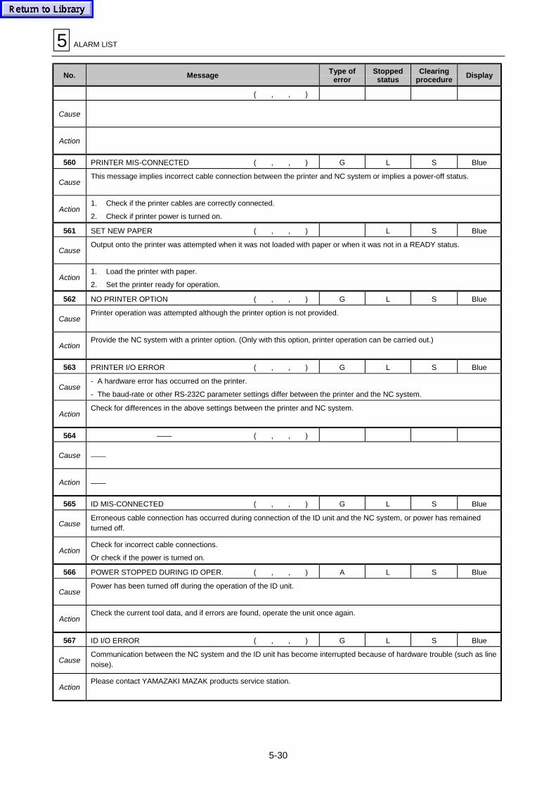
5 ALARM LIST
5-30
No. Message Type oferror
Stoppedstatus
Clearingprocedure
Display
( , , )
Cause
Action
560 PRINTER MIS-CONNECTED ( , , ) G L S Blue
CauseThis message implies incorrect cable connection between the printer and NC system or implies a power-off status.
Action1. Check if the printer cables are correctly connected.
2. Check if printer power is turned on.
561 SET NEW PAPER ( , , ) L S Blue
CauseOutput onto the printer was attempted when it was not loaded with paper or when it was not in a READY status.
Action1. Load the printer with paper.
2. Set the printer ready for operation.
562 NO PRINTER OPTION ( , , ) G L S Blue
CausePrinter operation was attempted although the printer option is not provided.
ActionProvide the NC system with a printer option. (Only with this option, printer operation can be carried out.)
563 PRINTER I/O ERROR ( , , ) G L S Blue
Cause- A hardware error has occurred on the printer.
- The baud-rate or other RS-232C parameter settings differ between the printer and the NC system.
ActionCheck for differences in the above settings between the printer and NC system.
564 —— ( , , )
Cause ——
Action ——
565 ID MIS-CONNECTED ( , , ) G L S Blue
CauseErroneous cable connection has occurred during connection of the ID unit and the NC system, or power has remainedturned off.
ActionCheck for incorrect cable connections.
Or check if the power is turned on.
566 POWER STOPPED DURING ID OPER. ( , , ) A L S Blue
CausePower has been turned off during the operation of the ID unit.
ActionCheck the current tool data, and if errors are found, operate the unit once again.
567 ID I/O ERROR ( , , ) G L S Blue
CauseCommunication between the NC system and the ID unit has become interrupted because of hardware trouble (such as linenoise).
ActionPlease contact YAMAZAKI MAZAK products service station.
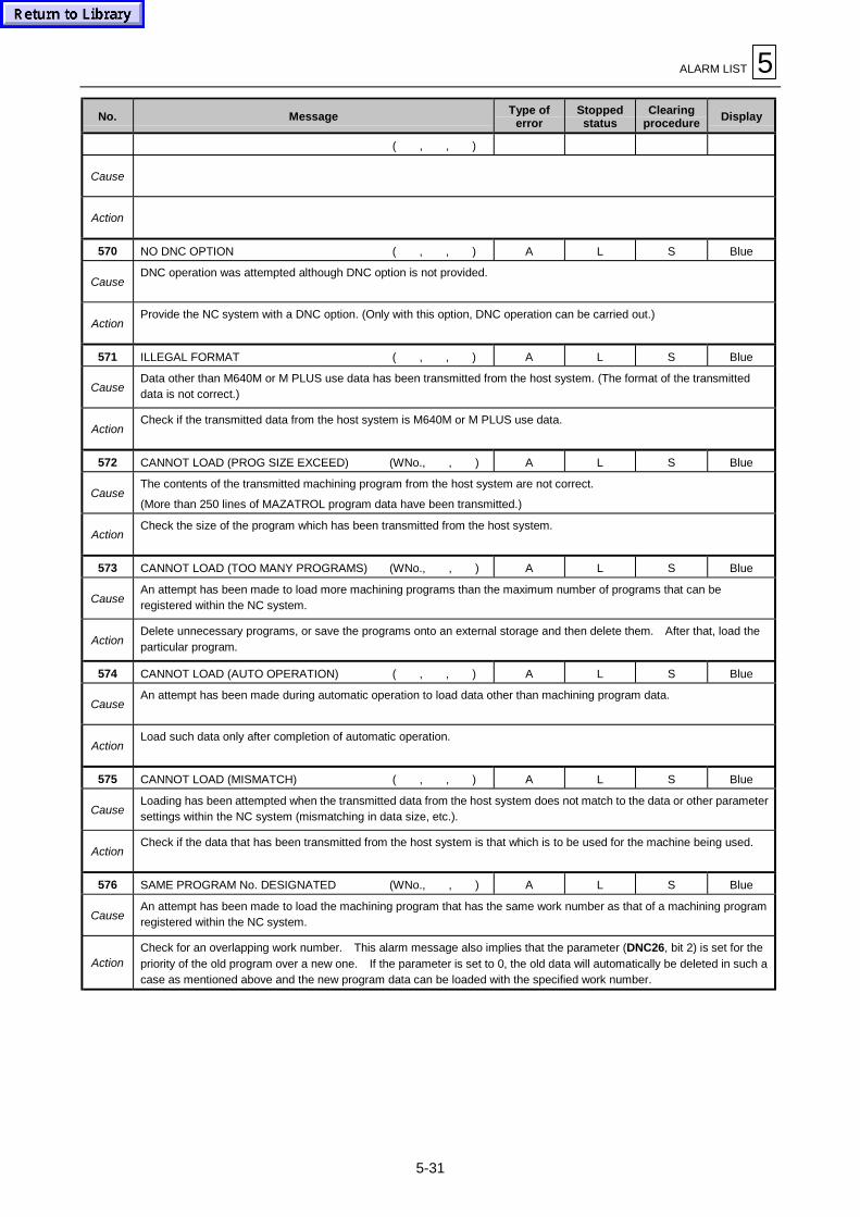
ALARM LIST 5
5-31
No. Message Type oferror
Stoppedstatus
Clearingprocedure
Display
( , , )
Cause
Action
570 NO DNC OPTION ( , , ) A L S Blue
CauseDNC operation was attempted although DNC option is not provided.
ActionProvide the NC system with a DNC option. (Only with this option, DNC operation can be carried out.)
571 ILLEGAL FORMAT ( , , ) A L S Blue
CauseData other than M640M or M PLUS use data has been transmitted from the host system. (The format of the transmitteddata is not correct.)
ActionCheck if the transmitted data from the host system is M640M or M PLUS use data.
572 CANNOT LOAD (PROG SIZE EXCEED) (WNo., , ) A L S Blue
CauseThe contents of the transmitted machining program from the host system are not correct.
(More than 250 lines of MAZATROL program data have been transmitted.)
ActionCheck the size of the program which has been transmitted from the host system.
573 CANNOT LOAD (TOO MANY PROGRAMS) (WNo., , ) A L S Blue
CauseAn attempt has been made to load more machining programs than the maximum number of programs that can beregistered within the NC system.
ActionDelete unnecessary programs, or save the programs onto an external storage and then delete them. After that, load theparticular program.
574 CANNOT LOAD (AUTO OPERATION) ( , , ) A L S Blue
CauseAn attempt has been made during automatic operation to load data other than machining program data.
ActionLoad such data only after completion of automatic operation.
575 CANNOT LOAD (MISMATCH) ( , , ) A L S Blue
CauseLoading has been attempted when the transmitted data from the host system does not match to the data or other parametersettings within the NC system (mismatching in data size, etc.).
ActionCheck if the data that has been transmitted from the host system is that which is to be used for the machine being used.
576 SAME PROGRAM No. DESIGNATED (WNo., , ) A L S Blue
CauseAn attempt has been made to load the machining program that has the same work number as that of a machining programregistered within the NC system.
ActionCheck for an overlapping work number. This alarm message also implies that the parameter (DNC26, bit 2) is set for the
priority of the old program over a new one. If the parameter is set to 0, the old data will automatically be deleted in such acase as mentioned above and the new program data can be loaded with the specified work number.

5 ALARM LIST
5-32
No. Message Type oferror
Stoppedstatus
Clearingprocedure
Display
577 NO DESIGNATED PROGRAM (WNo., , ) A L S Blue
Cause
- The machining program whose transmission from the NC system to the host system has been attempted does not existwithin the NC system.
- The machining program that has been designated using a control command (work number search or program deletion)does not exist within the NC system.
ActionCheck if the machining program with the specified work number exists in the NC system.
578 MEMORY CAPACITY EXCEEDED (WNo., , ) A L S Blue
CauseAn attempt has been made to load more machining programs than the maximum number of programs that can beregistered within the NC system.
ActionDelete unnecessary programs, or save the programs onto an external storage and then delete them. After that, load theparticular program.
579 MEMORY PROTECT ( , , ) A L S Blue
CauseLoading has been attempted when the PROGRAM LOCK/ENABLE switch setting was LOCK.
ActionSet the switch to ENABLE, and then carry out the loading operation. This alarm message also implies that the setting ofthe parameter (DNC26, bit 3) is OFF (0). Change this parameter setting to ON (1). Data loading will then becomepossible.
580 CARD NOT READY ( , , ) A L S Blue
CauseA memory card has not been correctly mounted in the NC system.
ActionCheck if the memory card is correctly mounted.
581 FLOPPY NOT READY ( , , ) A L S Blue
CauseA floppy disk has not been correctly mounted in the floppy disk drive.
ActionCorrectly mount a floppy disk in the floppy disk drive.
582 DESIGNATED FILE NOT TRANSFERED ( , , ) A L S Blue
CauseA file different from the one that has been requested from NC system to the host system was transferred from the latter.
ActionCheck the details of the file that has been transferred from the host system.
583 PROGRAM DATA TYPE INCORRECT ( , , ) A L S Blue
CauseAn attempt has been made to load a machining program that is different in structure from those stored within the NCsystem.
Action- Check if the program that has been transferred from the host system is for use with M640M or M PLUS.
- Check if the contents of the file transfer message (header block) are correct.
584 RECEIVED DATA TYPE INCORRECT ( , , ) A L S Blue
Cause
- An attempt has been made to load data other than machining program data and also different in structure from the datastored within the NC system.
- The contents of the header block or data block in the file transfer message (including machining programs) are notcorrect.
Action
- Check if the data that has been transferred from the host system is for use with M640M or for use with the machiningbeing operated.
- Check the contents of the header block (version number, etc.) or data block (sequence number, etc.) in the file transfermessage.

ALARM LIST 5
5-33
No. Message Type oferror
Stoppedstatus
Clearingprocedure
Display
585 CABLE MIS-CONNECTED ( , , ) G L S Blue
CauseThis message implies incorrect cable connection between the host system and the NC system or implies a power-off status.
Action
- Check if the DNC cables are correctly connected.
- Check if the host system is turned on and ready for data transmission/reception.
There may be cases that although a DNC option is provided, DNC itself is not to be used for the time being and thus theDNC cables are not yet connected. If this is the case, then set the appropriate parameter (DNC26, bit 1) to OFF (0). Thiswill clear the alarm display.
586 SYSTEM ERROR ( , , ) E L S Blue
CauseAn error has occurred within the system.
ActionPlease contact your YAMAZAKI MAZAK products service station. (At this time, also please notify them of what kind ofoperating procedure you had carried out before the alarm message appeared and what values were displayed inparentheses.)
587 PROG.OPERATION NOT ALLOWED (WNo., , ) A L S Blue
Cause
1. An attempt has been made to transmit a display inhibiting program to the host system. (Program managementfunction)
2. An attempt has been made to transmit to the host system the program being edited (or the program being loaded usinganother I/O unit).
Action
1. Check if the specified work number is for the program of display inhibition.
2. Carry out the transfer operation only after completion of the program editing (or program loading using another I/Ounit).
588 DATA OPERATION NOT ALLOWED ( , , ) A L S Blue
Cause
- An attempt has been made during automatic operation to load data other than machining program data.
- An attempt has been made to transmit to the host system the data being loaded using another I/O unit.
- An attempt has been made to load the data being saved using another I/O unit.
ActionWait until automatic operation has been completed (or until the loading or saving operation using another I/O unit has beencompleted).
589 DATA SIZE EXCEEDED (WNo., Note, ) A L S Blue
Cause
The EIA/ISO machining program includes a block that consists of more than 256 characters. (EOB or EOR is not presentwithin 256 characters.)
Note: The number displayed next to the work number is a line number, which corresponds to the number displayed in thelower right section of the PROGRAM display.
ActionCorrect the machining program. (Insert EOB within 256 characters.)
590 DNC COMMAND IMPOSSIBLE ( , , ) A L S Blue
Cause
The particular status of the NC system disables execution of the control command that has been requested from the hostsystem.
- A request for work number search has been made during automatic operation.
- During automatic operation, a request for deleting the machining program being used for the automatic operation hasbeen made.
ActionWait until the NC system becomes ready for processing or until the automatic operation is completed, and then make therequest once again.
591 NO OPTION (WNo., , ) A L S Blue
CauseAn attempt has been made to load (save) the data not supported by the current option of the DNC unit.
ActionOnly data supported by the option can be processed.

5 ALARM LIST
5-34
No. Message Type oferror
Stoppedstatus
Clearingprocedure
Display
592 ILLEGAL COMMAND RECEIVED ( , , ) A L S Blue
Cause
- The control command or file transfer command that has been requested from the host system is a nonexistent command.
- The machine number that has been designated for the loading of data other than machining program data does not agreewith any of the machine numbers within the NC system.
Action- Check the details of the command message that has been sent from the host system.
- Check if the machine number is the same as that registered within the NC system (parameter DNC19).
593 DNC I/O ERROR ( , , ) G L S Blue
Cause
- During use of DNC, processing has been aborted by line noise or other hardware factors.
- RS-232C communication parameter settings (such as those of the baud-rate, etc.) between the host system and NCsystem differ.
- Timer, number-of-retries or other settings are not correct.
Action
- Make line checks and hardware checks of the host and NC systems.
- Match the RS-232C communication parameter settings between the host system and NC system.
- Set the timer, number-of-retries, or other settings to those of the host system. (Parameters for the NC system: DNCparameters)
594 SEND-RECEIVE ERROR ( , , ) G L S Blue
Cause
- The preset number of retries has been exceeded during transmission/reception of command messages.
- RS-232C communication parameter settings (such as those of the baud-rate, etc.) between the host system and NCsystem differ.
- Timer, number-of-retries or other settings are not correct.
Action
- Make line checks and message checks of the host systems.
- Match the RS-232C communication parameter settings between the host system and NC system.
- Set the timer, number-of-retries or other settings to those of the host system. (Parameters for the NC system: DNCparameters)
595 FILE TRANSFER ERROR ( , , ) G L S Blue
Cause
- The preset number of retries has been exceeded during transmission/reception of the messages.
- RS-232C communication parameter settings (such as those of the baud-rate, etc.) between the host system and NCsystem differ.
- Timer, number-of-retries or other settings are not correct.
Action
- Make line checks and message checks of the host systems.
- Match the RS-232C communication parameter settings between the host system and NC system.
- Set the timer, number-of-retries or other settings to those of the host system. (Parameters for the NC system: DNCparameters)
596 DNC MALFUNCTION ( , , ) G L S Blue
CauseAn irretrievable hardware error has occurred during reception of the first message (ENQ) from the host system.
ActionAfter making hardware checks of the NC and host systems and line checks, turn the NC system power back on and thenrestart the receiving operation.
597 POWER OFF DURING DNC OPERATION ( , , ) A L S Blue
CausePower has been turned off during DNC operation.
ActionCheck for errors in the machining program being used, and if errors are found, carry out the DNC operation once again.Note, however, that if the machining program is being loaded, then loading must be carried out once again after erasing theloaded contents of the program.
598 NO EIA/ISO OPTION ( , , ) A L S Blue
CauseAn attempt has been made to transfer EIA/ISO program although the NC system is not provided with an EIA/ISO option.
ActionWithout an EIA/ISO option, EIA/ISO program processing is not possible.

ALARM LIST 5
5-35
No. Message Type oferror
Stoppedstatus
Clearingprocedure
Display
599 DESIGNATED DATA NOT FOUND ( , , ) A L S Blue
Cause
The host system has issued a request for transmission/reception of data not existing within the NC system.
- A drum-tool data transfer request has been issued to the NC system though it is not provided with a drum.
- A request for transfer of a larger volume of data than the control data stored within the NC system has been made.
ActionCheck the contents of the command messages that have been sent from the host system.

5 ALARM LIST
5-36
No. Message Type oferror
Stoppedstatus
Clearingprocedure
Display
600 —— ( , , )
Cause ——
Action ——
601 SYSTEM ERROR ( , , ) E I (L) O (S) Red (Blue)
CauseA processing error has occurred within the NC system.
ActionUsing data I/O operation (CMT), save the program data, tool data, tool file data, parameters, etc. that are currently beingused. After that, please contact your YAMAZAKI MAZAK products service station.
602 PROG. OPERATION NOT ALLOWED ( , , ) B I (L) O (S) Red (Blue)
CauseAn attempt has been made to start the program being transferred.
ActionAfter the transfer operation is completed, start the program.
603 NO DESIGNATED PROGRAM (WNo.,UNo.,SNo.) B I (L) O (S) Red (Blue)
Cause
- The program having the work number that has been set in the subprogram unit does not exist within the memory.
- No work number has been set in the subprogram unit.
- The work number that has been designated as the restart position does not exist within the memory.
ActionReview the machining programs to see if the designated program exists.
604 NO PITCH IN MULTI WORKPIECES (WNo.,UNo.,SNo.) B I (L) O (S) Red (Blue)
Cause- Pitch X is not yet set in spite of the fact that multi-piece machining in the direction of the X-axis is to take place.
- Pitch Y is not yet set in spite of the fact that multi-piece machining in the direction of the Y-axis is to take place.
ActionReview the particular machining program and then set an appropriate multi-piece machining pitch in the common unit.
605 NO TOOL DATA IN PROGRAM (WNo.,UNo.,SNo.) B I (L) O (S) Red (Blue)
CauseThe point-, line- or face-machining (including 3-D) unit does not contain any tool sequences.
ActionReview the particular machining program to see if there are units that do not contain necessary tool sequences.
606 NO FIGURE IN PROGRAM (WNo.,UNo.,SNo.) B I (L) O (S) Red (Blue)
CauseThe point-, line- or face-machining (including 3-D) unit does not have any shape data.
ActionReview the particular machining program to see if there are units that do not contain necessary shape data.
607 MISSING INPUT DATA (POINT) (WNo.,UNo.,SNo.) B I (L) O (S) Red (Blue)
CauseA point-machining unit lacks data.
ActionReview the particular machining program, and set data if a point-machining unit lacks data.
608 MISSING INPUT DATA (LINE) (WNo.,UNo.,SNo.) B I (L) O (S) Red (Blue)
CauseA line-machining unit lacks data.
ActionReview the particular machining program, and set data if a line-machining unit lacks data.

ALARM LIST 5
5-37
No. Message Type oferror
Stoppedstatus
Clearingprocedure
Display
609 MISSING INPUT DATA (FACE) (WNo.,UNo.,SNo.) B I (L) O (S) Red (Blue)
CauseA face-machining unit lacks data.
ActionReview the particular machining program, and set data if a face-machining unit lacks data.
610 MISSING TOOL DATA FOR POINT (WNo.,UNo.,SNo.) B I (L) O (S) Red (Blue)
CauseA point-machining tool sequence lacks data.
ActionReview the particular machining program, and set data if a point-machining tool sequence lacks data.
611 MISSING TOOL DATA FOR LINE (WNo.,UNo.,SNo.) B I (L) O (S) Red (Blue)
CauseA line-machining tool sequence lacks data.
ActionReview the particular machining program, and set data if a line-machining tool sequence lacks data.
612 MISSING TOOL DATA FOR FACE (WNo.,UNo.,SNo.) B I (L) O (S) Red (Blue)
CauseA face-machining (including 3-D) tool sequence lacks data.
ActionReview the particular machining program, and set data if a face-machining tool sequence lacks data.
613 DATA MISSING IN WPC UNIT (WNo.,UNo.,SNo.) B I (L) O (S) Red (Blue)
CauseThe WPC unit lacks data.
ActionReview the particular machining program, and set data if the WPC unit lacks data.
614 SUB PROGRAM NESTING EXCEEDED (WNo.,UNo.,SNo.) B I (L) O (S) Red (Blue)
CauseThe maximum permissible number of repeats of MAZATROL program nesting has been exceeded nine.
ActionReview and correct the particular machining program so that the total number of repeats of nesting does not excess nine.
615 DATA MISSING IN OFFSET UNIT (WNo.,UNo.,SNo.) B I (L) O (S) Red (Blue)
CauseThe offset unit lacks data.
ActionReview the particular machining program, and set data if the offset unit lacks data.
616 DATA ERROR IN M CODE UNIT (WNo.,UNo.,SNo.) B I (L) O (S) Red (Blue)
CauseThe M code unit contains no data.
ActionReview the particular machining program, and input data to the M code unit.
617 EXECUTION IMPOSSIBLE (WNo.,UNo.,SNo.) B I (L) O (S) Red (Blue)
CauseThe data processing operation cannot be performed because of contradiction in data. This condition occurs if an attemptis made to start automatic operation when the specified work number is an unregistered number.
ActionSearch out the contradictory data making reference to WNo., UNo., SNo. (which are displayed together with the alarmmessage), and then correct the data.

5 ALARM LIST
5-38
No. Message Type oferror
Stoppedstatus
Clearingprocedure
Display
618 POINT CUTTING PARAMETER ERROR (WNo.,UNo.,SNo.) B I (L) O (S) Red (Blue)
CauseThe point-machining parameter setting(s) is out of its permissible range.
Action
619 LINE/FACE CUTTING PAR. ERROR (WNo.,UNo.,SNo.) B I (L) O (S) Red (Blue)
CauseThe line- or face-machining parameter settings are out of their permissible ranges.
ActionThe parameter E13 is set to ”0”; change it to a value other than ”0”.
620 CUTTING SPEED ZERO (WNo.,UNo.,SNo.) B I (L) O (S) Red (Blue)
CauseOf tool sequence data (except for chip removal), the circumferential speed (C-SP) is unset or set to “0”.
ActionReview the machining program and set the desired circumferential speed (C-SP).
621 FEEDRATE ZERO (WNo.,UNo.,SNo.) B I (L) O (S) Red (Blue)
CauseOf tool sequence data (except for chip removal), the feedrate (FR) is unset or set to “0”.
ActionReview the machining program and set the desired feedrate (FR).
622 DESIGNATED UNIT NOT FOUND ( , , ) B I (L) O (S) Red (Blue)
CauseThe unit that has been designated as the restart position is not present in the program with the specified work number.
ActionReview the machining program and designate the correct unit number.
623 DESIGNATED SNo. NOT FOUND ( , , ) B I (L) O (S) Red (Blue)
CauseThe tool sequence that has been designated as the restart position is not present in the unit of the specified work number;two or more lines of tool sequence data are present in the line-machining chamfering unit.
ActionReview the machining program and designate the correct tool sequence number.
624 RESTART IMPOSSIBLE ( , , ) B I (L) O (S) Red (Blue)
Cause
- The unit that has been designated as the restart position is the end unit.
- The designated number of times of reappearance (L) is too large and the corresponding restart position is not present.
- The restart data is incomplete.
ActionCheck the contents of the restart data or the program.
625 ENDMILL DIAMETER EXCEEDED (WNo.,UNo.,SNo.) B I (L) O (S) Red (Blue)
Cause- The value of “(groove width) – (finish allowance R) × 2” of the endmill groove unit is smaller than the “tool diameter” value
of the rough-machining tool.
- The “groove width” value of the endmill groove unit is smaller than the “tool diameter” value of the finishing tool.
Action
626 NO TOOL IN MAGAZINE (WNo.,UNo.,SNo.) B I (L) O (S) Red (Blue)
CauseThe tool(s) specified in the program is not registered in the tool data.
ActionCarry out a tool layout operation and register the necessary tool(s) on the TOOL DATA display.

ALARM LIST 5
5-39
No. Message Type oferror
Stoppedstatus
Clearingprocedure
Display
627 TOOL DATA INPUT PROCESS ERROR (WNo.,UNo.,SNo.) B I (L) O (S) Red (Blue)
CauseThe data of the tool length or tool diameter is not yet input on the TOOL DATA display.
ActionReview the tool data and input the tool length or tool diameter.
628 NO ASSIGNED TOOL IN TOOL FILE (WNo.,UNo.,SNo.) B I (L) O (S) Red (Blue)
CauseThe tool specified in the program is not registered on the TOOL FILE display.
ActionRegister the tool data that is to be used in the program into the tool file.
629 TOOL FILE INPUT PROCESS ERROR (WNo.,UNo.,SNo.) B I (L) O (S) Red (Blue)
CauseThe tool file lacks of data.
ActionReview the data on the TOOL FILE display and fill in any empty items with data.
630 Z DEPTH OF CUT TOO LARGE (WNo.,UNo.,SNo.) B I (L) O (S) Red (Blue)
CauseOf the line- or face-machining tool sequence data, the value of the Z depth of cut is in excess of the depth of cut on theTOOL FILE display.
ActionReview the machining program and correct the value of the Z depth of cut.
631 STOCK REMOVAL R TOO LARGE (WNo.,UNo.,SNo.) B I (L) O (S) Red (Blue)
Cause
The value of “(removal allowance R) – (finish allowance R)” in the line-machining unit is larger than the value of the tooldiameter of the rough-cutting tool.
The value of removal allowance R in the line-machining unit is larger than the value of the tool diameter of the finishing tool.
ActionReview the machining program and correct the values of removal allowance R and finishing allowance R in the line-machining unit.
632 RADIAL DEPTH OF CUT ZERO (WNo.,UNo.,SNo.) B I (L) O (S) Red (Blue)
CauseOf line- or face-machining tool sequence data, the radial depth of cut is set to zero or smaller.
ActionReview the machining program and set the radial depth of cut to the correct value.
633 Z DEPTH OF CUT ZERO (WNo.,UNo.,SNo.) B I (L) O (S) Red (Blue)
CauseOf line- or face-machining tool sequence data, the Z depth of cut is set to zero or smaller.
ActionReview the machining program and set the Z depth of cut to the correct value.
634 FINISH DEPTH OF CUT ZERO (WNo.,UNo.,SNo.) B I (L) O (S) Red (Blue)
CauseThe finish allowance value in the line- or face-machining unit is set to zero in spite of the fact that a finishing tool isregistered.
ActionReview the machining program and set data in the finish allowance data item.
635 TOOL DIAMETER ZERO (WNo.,UNo.,SNo.) B I (L) O (S) Red (Blue)
CauseOf tool data, the tool diameter setting is zero.
ActionReview the data on the TOOL DATA display and set data in the tool diameter item.

5 ALARM LIST
5-40
No. Message Type oferror
Stoppedstatus
Clearingprocedure
Display
636 STOCK REMOVAL Z TOO SMALL (WNo.,UNo.,SNo.) B I (L) O (S) Red (Blue)
CauseIn the line- or face-machining unit, removal allowance Z is smaller than finish allowance Z.
ActionReview the line- or face-machining unit and increase removal allowance Z to a value greater than that of finish allowance Z.
637 STOCK REMOVAL R TOO SMALL (WNo.,UNo.,SNo.) B I (L) O (S) Red (Blue)
CauseIn the line- or face-machining unit, removal allowance R is smaller than finish allowance R.
ActionReview the line- or face-machining unit and increase the value of removal allowance R to a value greater than that of finishallowance R.
638 R DEPTH OF CUT TOO LARGE (WNo.,UNo.,SNo.) B I (L) O (S) Red (Blue)
CauseOf the face-machining tool sequence data, the setting of the radial depth of cut is smaller than the tool diameter setting onthe TOOL DATA display.
ActionReview the machining program and increase the radial depth of cut to a value greater than the tool diameter setting in thetool data.
639 DESIGNATED PALLET NOT FOUND (WNo.,UNo.,SNo.) B I (L) O (S) Red (Blue)
CauseThe pallet number that has been set in the pallet changing unit is larger than the maximum allowable number of pallets setin the parameter L46.
ActionReview the machining program and set an allowable pallet number.
640 ILLEGAL INDEX ANGLE INPUT (WNo.,UNo.,SNo.) B I (L) O (S) Red (Blue)
CauseThe data that has been set in the angle item of the indexing unit is that which cannot be divided by the parameter L37setting (minimum allowable angle of index).
ActionReview the machining program and set an allowable angle of index.
641 MISSING INPUT DATA (WNo.,UNo.,SNo.) B I (L) O (S) Red (Blue)
CauseThe pallet changing unit or the indexing unit lacks of unit data.
Initial point Z is not yet set in the common unit.
ActionReview the machining program and set all the necessary values in the unit.
642 ILLEGAL NEXT PALLET No. INPUT (WNo.,UNo.,SNo.) B I (L) O (S) Red (Blue)
CauseThe same pallet number as the current pallet number has been set as the next one.
ActionReview the machining program and make sure of the pallet numbers.
643 DATA ERROR IN MAN. PROG. UNIT (WNo.,UNo.,SNo.) B I (L) O (S) Red (Blue)
CauseThe manual program mode unit contains a sequence that has no data.
ActionReview the machining program, and fill in any incomplete sequence with data or erase such sequences.
644 NOMINAL DIAMETER NOT FOUND (WNo.,UNo.,SNo.) B I (L) O (S) Red (Blue)
CauseThe nominal diameter item of the tool sequence data is not complete. The nominal diameter item of the MMS unit or themanual program mode unit (when a tool is set) is not complete.
ActionReview the machining program, and set data in the nominal diameter item of the MMS unit or the manual program modeunit (when a tool is set) or erase the corresponding portion.

ALARM LIST 5
5-41
No. Message Type oferror
Stoppedstatus
Clearingprocedure
Display
645 PRIORITY No. OVERLAP (WNo.,UNo.,SNo.) B I (L) O (S) Red (Blue)
CauseThe same priority number is assigned to different tools.
ActionWithin one process, the same priority number must not be assigned to different tools.
Change the priority number.
646 ILLEGAL PRIORITY NUMBER (WNo.,UNo.,SNo.)*
(LNo. 1, LNo. 2, )**
B I (L) O (S) Red (Blue)
Cause
The priority numbering order within a unit is not correct.
* During setting the priority numbers on the PROGRAM display.
** During setting the priority numbers on the PROGRAM LAYOUT display - data in the layout lines LNo. 1 and LNo. 2 arenot correct.
ActionThe machining order within one unit has been reversed by the incorrect priority numbering.
Change the priority numbers.
647 END UNIT NOT FOUND (WNo.,UNo.,SNo.) B I (L) O (S) Red (Blue)
CauseThe end unit is not present in the program.
ActionReview the machining program and set the end unit at the end of the program.
648 MULTI OFFSET DATA TOO LARGE (WNo.,UNo.,SNo.) B I (L) O (S) Red (Blue)
CauseMore than 10 sets of offset data have been input for multi-piece machining.
ActionThe machining program is in an abnormal state. If the program is already saved onto CMT, microdisk or other media,erase the program and then reload it. If the program is not yet saved, make corrections with the editing function and fullyscan for more data errors.
649 MMS SEQUENCE INCOMPLETE (WNo.,UNo.,SNo.) B I (L) O (S) Red(Blue)
CauseThe MMS sequence lacks of data.
ActionReview the machining program, and input data to the MMS sequence to make it complete.
650 CHAMFERING IMPOSSIBLE (WNo.,UNo.,SNo.) B I (L) O (S) Red (Blue)
Cause
Cutting is impossible because the chamfering cutter is likely to come into contact with the wall or bottom of the workpieceduring chamfering.
The data of the specified chamfering cutter on the TOOL DATA or TOOL FILE display is not appropriate.
ActionReview the machining program or the tool file, and correct inappropriate data.
651 GEAR PARAMETER ERROR (WNo.,UNo.,SNo.) B I (L) O (S) Red (Blue)
CauseAn attempt has been made to execute the point-, line- or face-machining MAZATROL program when the setting ofparameter L28 was “5” or more.
ActionChange the setting of parameter L28 to a value between 0 and 4.
Action
Change the corresponding code(s) to an available one(s).
4-gear H : M39
MH : M38
ML : M37
L : M36
2-gear H : M39
L : M38
3-gear H : M39
M : M38
L : M37

5 ALARM LIST
5-42
No. Message Type oferror
Stoppedstatus
Clearingprocedure
Display
653 ILLEGAL TOOL DESIGNATED (WNo.,UNo.,SNo.) B I (L) O (S) Red (Blue)
CauseTools that cannot be used have been designated.
ActionReview the machining program and designate tools that are usable.
654 TOOL DATA ERROR (WNo.,UNo.,SNo.) B I (L) O (S) Red (Blue)
CauseThe tool length and tool diameter settings on the TOOL DATA display are negative.
ActionSet positive tool length and tool diameter values.
655 PROGRAM DATA CORRUPT (WNo.,UNo.,SNo.) B I (L) O (S) Red (Blue)
CauseThe program is destroyed.
ActionErase a part of the program and then re-create the destroyed part; or erase the entire program and then carry out a loadingoperation using the data I/O operation (CMT) or other functions once again.
656 MMS SEQUENCE DATA NOT FOUND (WNo.,UNo.,SNo.) B I (L) O (S) Red (Blue)
CauseThe MMS units include one that has no sequence data.
ActionCreate one or more lines of sequence data in the corresponding MMS unit, or erase the unit.
657 ILLEGAL NUMBER INPUT (WNo.,UNo.,SNo.) B I (L) O (S) Red (Blue)
CauseThe program contains incorrect data.
ActionReview the machining program and make data corrections.
658 INITIAL Z < MATERIAL DEPTH (WNo.,UNo.,SNo.) B I (L) O (S) Red (Blue)
CauseThe setting of the material height in the 3-D machining unit is greater than that of initial point Z in the common unit.
ActionChange the program to give a material height value smaller than the initial point Z value.
659 NO TOOL PATH CHECK (I/O BUSY) (WNo., , ) A L S Blue
CauseThe tool path check cannot be performed since I/O operation (loading) is in progress.
ActionMake the tool path check after the I/O operation has been completed.
660 CANNOT MOVE DESIGNATED AXIS ( , , ) B I (L) O (S) Red (Blue)
CauseThe Y-axis or Z-axis of the index position has been appointed using the indexing unit when the parameter L41 is set to “2”.
ActionUsing the data cancellation key, erase the Y-axis or Z-axis data of the index position.
661 ILLEGAL M CODE (WNo.,UNo.,SNo.)
CauseM195 (tool breakage detection start command code) has been set for the M code unit or for the manual program modesequence.
ActionM195 cannot be executed on MAZATROL programs. Delete that command code from the program.

ALARM LIST 5
5-43
No. Message Type oferror
Stoppedstatus
Clearingprocedure
Display
662 NO INCLINED PLANE OPTION (WNo., UNo., ) B I (L) O (S) Red (Blue)
CauseAn attempt has been made to execute the inclined-plane machining program in the absence of an inclined-plane machiningoption.
ActionInclined-plane machining is not possible because of the absence of an inclined-plane machining option.
<HV>
663 WRONG HEAD ANGLE (WNo., UNo., ) B I (L) O (S) Red (Blue)
Cause
1. A corner-face unit or plane inclination measurement has been designated in process data other than inclined-planemachining process data.
2. Table rotational machining has been designated in spite of the fact that the facial angle data in the face definitionsequence is not for the top plane.
3. Calibration measurement has been designated for the top plane or an inclined plane.
4. Groove center, hole center, boss center, and step width measurements have been designated for an inclined plane.
Action
1. A corner-face unit and plane inclination measurement can be designated only for an inclined plane.
2. Table rotational machining can be executed only for the top plane.
3. Calibration measurement is possible only for the side.
4. Only reference plane measurement and plane inclination measurement are possible for inclined planes.
<HV>
664 3-D UNIT NOT FOUND IN PROGRAM (WNo.,UNo.,SNo.) B I (L) O (S) Red (Blue)
CauseA 3-D machining unit has been set in the program in spite of the fact that 3-D machining option is not provided.
ActionErase the 3-D machining unit from the machining program.
665 ILLEGAL DATA IN 3-D UNIT (WNo.,UNo.,SNo.) B I (L) O (S) Red (Blue)
CauseThe 3-D machining unit lacks of unit data.
ActionReview the machining program and set necessary data in the 3-D machining unit.
666 PLANE DATA NOT FOUND IN PROGRAM (WNo.,UNo.,SNo.) B I (L) O (S) Red (Blue)
CauseThe 3-D machining unit lacks of plane definition data.
ActionReview the machining program and set plane definition data in the 3-D machining unit.
667 CHECK SURFACE DATA NOT FOUND (WNo.,UNo.,SNo.) B I (L) O (S) Red (Blue)
CauseThe 3-D machining unit lacks of check surface data.
ActionReview the machining program and set check surface data in the 3-D machining unit.
668 ILLEGAL PLANE DATA IN PROGRAM (WNo.,UNo.,SNo.) B I (L) O (S) Red (Blue)
CauseThe plane definition data in the 3-D machining unit is not complete.
ActionReview the machining program and set data in the plane definition data item.
669 ILLEGAL TOLERANCE DATA INPUT (WNo.,UNo.,SNo.) B I (L) O (S) Red (Blue)
CauseThe value of the tolerance parameter that has been designated in the tool sequence is “0”
ActionCheck the parameters E67 through E75, and set a value other than “0” in the parameter whose setting is “0”.

5 ALARM LIST
5-44
No. Message Type oferror
Stoppedstatus
Clearingprocedure
Display
670 ILLEGAL SEQUENCE DATA IN PRG. (WNo.,UNo.,SNo.) B I (L) O (S) Red (Blue)
CauseThe tool sequence in the 3-D machining unit lacks of data.
ActionReview the machining program and input data to the tool sequence.
671 ILLEGAL MOVE SURFACE DATA (WNo.,UNo.,SNo.) B I (L) O (S) Red (Blue)
CauseThe coordinate conversion data in the 3-D machining unit is not complete.
ActionReview the machining program and make the coordinate conversion data complete.
672 ILLEGAL AREA DATA INPUT (WNo.,UNo.,SNo.) B I (L) O (S) Red (Blue)
CauseIn the check surface data of the 3-D machining unit, the setting of the maximum value is smaller than that of the minimumvalue.
ActionReview the check surface data, and make corrections so that the setting of the maximum value is equal to or greater thanthat of the minimum value for each axis.
673 FL NUMBER EXCEEDED (3-D UNIT) (WNo.,UNo.,SNo.) B I (L) O (S) Red (Blue)
CauseIn the ruled-surface unit, the number of FLs is in excess of 20, or in the line- or face-machining unit, the number of definedfigures is in excess of 2.
ActionReview the machining program and correct the shape data.
674 NO 5FACE CUTTING OPTION (WNo., UNo., ) B I (L) O (S) Red (Blue)
CauseAn attempt has been made to execute a five-surface machining program when the five-surface machining option was notpresent.
ActionSet the five-surface machining option to execute a five-surface machining program.
675 ILLEGAL CUTTING FACE DESIGNATED (WNo.,UNo.,SNo.) B I (L) P (S) Red (Blue)
CauseA face that cannot be cut with the selected head has been designated.
ActionChange either the selected face or the head.
676 ILLEGAL UNIT (WNo., UNo., ) B I (L) O (S) Red (Blue)
Cause
1. The face definition unit or five-surface machining unit includes illegal units and measurement sequences.Illegal units and sequences:face definition unit, pallet change unit, process end unit, index unit, WPC unit, and measurement of workpieceinclination.
2. An MMS unit has been set in the program that has table rotational machining designated in its face definitionsequence.
Action
1. Remove all illegal units and sequences from the machining program.
2. MMS measurement is not possible while table rotational machining is effective.
<HV>
677 UNREGISTERED HEAD DATA (WNo., UNo., ) B I (L) P (S) Red (Blue)
CauseHead data corresponding to the head of the designated head number does not exist.
ActionReview the designated head number.

ALARM LIST 5
5-45
No. Message Type oferror
Stoppedstatus
Clearingprocedure
Display
678 NO INTERSECTION (WNo.,UNo.,SNo.) B I (L) O (S) Red (Blue)
CauseIn the line- or face-machining unit, the coordinates of the intersection point of figures cannot be obtained because ofshortage of, or contradiction, in the free-shape data.
Action
679 CONNECTING CORNER IMPOSSIBLE (WNo.,UNo.,SNo.) B I (L) O (S) Red (Blue)
CauseThe figures cannot be connected smoothly at corner R because of contradiction in the data of corner R or in the data of thefigures in front and rear of corner R.
ActionReview the machining program and check the value of corner R of the free shapes.
680 NUMBER OF HOLES EXCEEDED (>500) (WNo.,UNo.,SNo.) B I (L) O (S) Red (Blue)
CauseThe point-machining units include one(s) that has more than 500 holes defined in it.
ActionReview the point-machining units, and make corrections so that the total number of hole settings in one point-machiningunit in not greater than 500.
681 CORNER R/C DEFINED AT SPT/FPT (WNo.,UNo.,SNo.) B I (L) O (S) Red (Blue)
CauseCorner rounding or corner chamfering has been set at the starting or ending point of a figure when defining figures in thecentral linear machining, right-hand linear machining, left-hand linear machining, right-hand chamfering or left-handchamfering units.
ActionReview the machining program and correct it so that the corner rounding or corner chamfering is not set at the starting orending point.
682 ILLEGAL REPEAT FIGURE (WNo.,UNo.,SNo.) B I (L) O (S) Red (Blue)
CauseContradiction presides in the figure rotation or figure shift data that has been set during defining free figures in the line- orface-machining unit.
ActionReview and correct the corresponding shape data.
683 UNDEFINED CORNER (WNo.,UNo.,SNo.) B I (L) O (S) Red (Blue)
CauseThe value of designated corner rounding or corner chamfering is not appropriate.
ActionReview the corresponding shape data and set the correct corner rounding or corner chamfering value.
684 POINT CUTTING PATTERN ERROR (WNo.,UNo.,SNo.) B I (L) O (S) Red (Blue)
CauseThe point-machining shape definition data is not appropriate.
ActionReview and correct the corresponding shape data.
685 SQUARE CANNOT BE DEFINED (WNo.,UNo.,SNo.) B I (L) O (S) Red (Blue)
CauseWhen the shape pattern is “square”, the input data cannot be used to make shape definitions.
ActionReview and correct the corresponding shape data.
686 NO STARTING POINT (WNo.,UNo.,SNo.) B I (L) O (S) Red (Blue)
CauseDuring input of free-shape data (open-figure data) to the line-machining unit, “?” has been set as the definition of the startingpoint.
ActionReview the machining program and set the coordinates of the starting point of the free shape.

5 ALARM LIST
5-46
No. Message Type oferror
Stoppedstatus
Clearingprocedure
Display
687 NO FINISH POINT (WNo.,UNo.,SNo.) B I (L) O (S) Red (Blue)
CauseDuring input of free-shape data (open-figure data) to the line-machining unit, “?” has been set as the definition of the endingpoint.
ActionReview the machining program and set the coordinates of the ending point of the free shape.
688 INSUFFICIENT INPUT DATA (WNo.,UNo.,SNo.) B I (L) O (S) Red (Blue)
CauseThe coordinates of the intersection point cannot be calculated since the free-shape input data in the line- or face-machiningunit is incomplete.
ActionReview the corresponding shape data and set data that is wanting.
689 INPUT DATA TOO MANY (WNo.,UNo.,SNo.) B I (L) O (S) Red (Blue)
Cause
1. The line- or face-machining unit contains too much free-shape input data, and there is contradiction betweenoverlapping data.
2. Too many tool sequences have been set for the line- or face-machining unit.
Action1. Review the corresponding shape data and erase either one of the overlapping data sets.
2. Reduce the number of tool sequences.
690 ILLEGAL RADIUS (WNo.,UNo.,SNo.) B I (L) O (S) Red (Blue)
CauseContradiction exists in the free-shape data that have been set to define arc in the line- or face-machining units.
ActionReview the corresponding shape data and set correct data.
691 MOUNT (VALLEY) SHAPE ERROR (WNo.,UNo.,SNo.) B I (L) O (S) Red (Blue)
CauseThe second figures (inside figures) are not yet defined in the endmilling-mountain, pocket milling-mountain or pocketmilling-valley unit.
ActionReview the machining program, and define the second shape in the endmilling-mountain, pocket milling-mountain or pocketmilling-mountain unit.
692 MAX POINT NUMBER EXCEEDED (>200) (WNo.,UNo.,SNo.) B I (L) O (S) Red (Blue)
CauseThe number of points which are necessary to define the shapes designated in the line- or face-machining unit exceeds 200.
ActionReview the machining program, and reduce the number of shapes within one line- or face-machining unit.
693 NUMBER OF SHAPES TOO LARGE (WNo.,UNo.,SNo.) B I (L) O (S) Red (Blue)
CauseAmong the line- or face-machining units is one(s) that contains more shapes than allowable within one unit.
ActionReview the corresponding shape data and check the number of shapes.
694 FIXED FIGURE DESIGNATED ERROR (WNo.,UNo.,SNo.) B I (L) O (S) Red (Blue)
CauseFixed shapes are included in the shape data (open figures) of the central linear machining, right-hand linear machining,left-hand linear machining, right-hand chamfering, left-hand chamfering or endmilling-groove units.
ActionChange the fixed shapes to free ones.
695 POINT INSIDE CIRCLE (WNo.,UNo.,SNo.) B I (L) O (S) Red (Blue)
CauseIt is not possible to draw a tangent line from point P1 since it is inside the arc.
ActionReview the machining program and check the free-shaped data.

ALARM LIST 5
5-47
No. Message Type oferror
Stoppedstatus
Clearingprocedure
Display
696 ILLEGAL DIRECTION (WNo.,UNo.,SNo.) B I (L) O (S) Red (Blue)
Cause“Left” or “right” is set in P, though “up” or “down” should have been set.
ActionReview the machining program and check the value of P.
697 DATUM <P> REQUIRED (WNo.,UNo.,SNo.) B I (L) O (S) Red (Blue)
CauseP is not yet input in spite of the fact that there are more than one point of intersection with the arc.
ActionReview the machining program and set P.
698 TWO POINTS OVERLAP (WNo.,UNo.,SNo.) B I (L) O (S) Red (Blue)
CauseThe coordinate values of the start point and end point are the same.
ActionFor the pattern of straight line, the data of X/Y are set to exactly the same end point coordinate values as X/Y present on thepreceding line of the program; delete these data.
699 PARALLEL LINE (WNo.,UNo.,SNo.) B I (L) O (S) Red (Blue)
CauseThe two straight lines are parallel to each other, and thus the coordinates of their intersection point cannot be obtained.
ActionReview the corresponding shape data and set correct data.

5 ALARM LIST
5-48
No. Message Type oferror
Stoppedstatus
Clearingprocedure
Display
700 —— ( , , )
Cause ——
Action ——
701 DEFINED SHAPE TOO SMALL (WNo.,UNo.,SNo.) B K O Blue
CauseThe shape compensation clearance with respect to the shape of the endmilling-top is too large; or the tool diameter withrespect to the size of the line-inside machining is too large.
ActionChange the shape compensation clearance (parameter E13) to an approriate value: or use a tool of smaller diameter.
702 FIGURE DEFINITION ERROR (WNo.,UNo.,SNo.) B K O Blue
CauseThe input shape is contradictory to logic, that is, the radius of the arc, for example, does not agree with the distance fromthe center.
ActionSuch contradiction usually results from arithmetic errors. Change the radial depth of cut by some micro, or use a tool ofsmaller diameter.
703 PROCESS DEFINITION ERROR (WNo.,UNo.,SNo.) B K O Blue
CauseThe machining conditions are incorrect (for example, the radial depth of cut is zero).
ActionChange the machining conditions to correct ones.
704 TOOL INTERFERENCE (WNo.,UNo.,SNo.) B K O Blue
CauseIn area machining, the tool diameter with respect to the figure is too large.
ActionReplace the tool with one that has a smaller diameter; or select the M2 mode endmilling-step machining pattern with settingbit 7 of parameter E91 if this error occurs in the outside machining endmilling-step.
705 APPROACH POINT ERROR (WNo.,UNo.,SNo.) B K O Blue
CauseThe approach point cannot be obtained.
ActionReduce the tool diameter, the approach amount (parameters E1, E2) and/or the overlap amount (parameter E21).
706 ILLEGAL FIGURE DATA (WNo.,UNo.,SNo.) B K O Blue
Cause
- The shape has been separated into three segments or more as a result of offsetting.
- The inside form does not contain the center of the outside form for outside-related fixed path.
- The outside form is concave for inside-related fixed path.
- The inside form is not adequate since it contains a concave or an intersection.
ActionChange the machining pattern (from inversed type to fixed type, for example); or divide the machining shape in advance sothat it will not be separated by offsetting.
707 CHAMFER CUTTER INTERFERENCE (WNo.,UNo.,SNo.) B K O Blue
CauseThe chamfering tool interferes with the side wall or bottom.
ActionUse a tool which does not interfere with the side wall or bottom.

ALARM LIST 5
5-49
No. Message Type oferror
Stoppedstatus
Clearingprocedure
Display
708 BLOCK DATA LIMIT EXCEEDED (WNo.,UNo.,SNo.) B L S Blue
CauseIn the EIA program, the total number of characters within one block is in excess of 248.
ActionDivide blocks so that one block contains 248 characters or less.
750 CURVE DEFINITION ERROR (WNo.,UNo.,SNo.) B K O Blue
CauseA curved surface that cannot be machined has been defined.
ActionNo corrective actions can be taken against this error; define a curved surface that can be machined.
751 CURVE DEFINITION ERROR (WNo.,UNo.,SNo.) B K O Blue
CauseA curved surface that cannot be machined has been defined.
ActionNo corrective actions can be taken against this error; define a curved surface that can be machined.
752 DESIGNATED AREA DATA IMPOSSIBLE (WNo.,UNo.,SNo.) B K O Blue
Cause
The check surface values are incorrect.
1. For rough-machining 1 or 2: Check surface Z min. ≥ material height
2. For finishing: Check surface Z min. > initial Z
3. Check surface X min. > X max., or Y min. > Y max., or Z min. > Z max.
Action
Set the check surface values as follows:
1. For rough-machining 1 or 2: Check surface Z min. < material height
2. For finishing: Check surface Z min. ≤ initial Z
3. Check surface X min. ≤ X max., and Y min. ≤ Y max., and Z min. ≤ Z max.
753 SMALL TOOL (WNo.,UNo.,SNo.) B K O Blue
CauseIn rough-machining 2, the tool diameter is extremely small in comparison with the dimensions of the defined 3-D figure.
ActionUse tools whose diameters are no less than 1/100 of the distance between the maximum and minimum dimensions of the3-D figure.
754 LARGE TOOL (WNo.,UNo.,SNo.) B K O Blue
CauseTool interference has occurred.
ActionNote: Currently, this error message does not actually appear since an automatic tool-interference checking function is not
provided. Here, this message is covered just to allow for future possible system expansion.
755 R DIRECTION PITCH SMALL (WNo.,UNo.,SNo.) B K O Blue
CauseIn rough-machining 2, the pitch in the radial direction is extremely small in comparison with the dimensions of the defined3-D figure.
ActionSet the radial-direction pitch to a value no less than 1/200 of the distance between the maximum and minimum dimensionsof the 3-D figure.

5 ALARM LIST
5-50
No. Message Type oferror
Stoppedstatus
Clearingprocedure
Display
756 Z DIRECTION PITCH SMALL (WNo.,UNo.,SNo.) B K O Blue
CauseIn rough-machining 2, the pitch in the Z direction is extremely small in comparison with the dimensions of the defined 3-Dfigure.
ActionSet the Z-direction pitch to a value no less than 1/250 of (material height – height of the Z bottom of the 3-D figure).
757 CURVE DEFINITION LARGE (WNo.,UNo.,SNo.) B K O Blue
Cause
- For rough-machining 2 with designation of workpiece size, the dimensions of the defined figure are larger than those ofthe workpiece.
- For rough-machining 2, a material height smaller than “(height of the Z bottom of the 3-D figure) + (height of a machiningarea outside the figure)” [parameters E84, E89] has been set irrespective of designating the offset amount or theworkpiece size.
ActionChange the E84 and E89 parameter settings so that: for the offset amount designation, “(height of the bottom of the 3-Dfigure) + E84 < material height”, and; for the workpiece size designation, “(height of the bottom of the 3-D figure) + E89 <material height”.
758 INITIAL POINT SET ERROR (WNo.,UNo.,SNo.) B K O Blue
CauseIn rough-machining 1 or 2, initial Z ≤ material height.
ActionChange settings to give initial Z > material height.
( , , )
Cause
Action
780 APPROACH PATH INTERFERENCE (WNo.,UNo.,SNo.) B L O Blue
CauseThe programmed approach path or retraction path interferes with the stock material (programmed shape plus removalallowance).
ActionReduce the approach amount/overlap amount or use a tool of smaller diameter; or set the approach point in a differentposition.
( , , )
Cause
Action
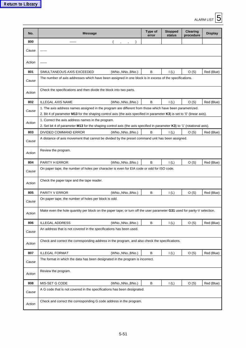
ALARM LIST 5
5-51
No. Message Type oferror
Stoppedstatus
Clearingprocedure
Display
800 —— ( , , )
Cause ——
Action ——
801 SIMULTANEOUS AXIS EXCEEDED (WNo.,NNo.,BNo.) B I (L) O (S) Red (Blue)
CauseThe number of axis addresses which have been assigned in one block is in excess of the specifications.
ActionCheck the specifications and then divide the block into two parts.
802 ILLEGAL AXIS NAME (WNo.,NNo.,BNo.) B I (L) O (S) Red (Blue)
Cause1. The axis address names assigned in the program are different from those which have been parametrized.
2. Bit 4 of parameter M13 for the shaping control axis (the axis specified in parameter K3) is set to ‘0’ (linear axis).
Action1. Correct the axis address names in the program.
2. Set bit 4 of parameter M13 for the shaping control axis (the axis specified in parameter K3) to ‘1’ (rotational axis).
803 DIVIDED COMMAND ERROR (WNo.,NNo.,BNo.) B I (L) O (S) Red (Blue)
CauseA distance of axis movement that cannot be divided by the preset command unit has been assigned.
ActionReview the program.
804 PARITY H ERROR (WNo.,NNo.,BNo.) B I (L) O (S) Red (Blue)
CauseOn paper tape, the number of holes per character is even for EIA code or odd for ISO code.
ActionCheck the paper tape and the tape reader.
805 PARITY V ERROR (WNo.,NNo.,BNo.) B I (L) O (S) Red (Blue)
CauseOn paper tape, the number of holes per block is odd.
ActionMake even the hole quantity per block on the paper tape; or turn off the user parameter G31 used for parity-V selection.
806 ILLEGAL ADDRESS (WNo.,NNo.,BNo.) B I (L) O (S) Red (Blue)
CauseAn address that is not covered in the specifications has been used.
ActionCheck and correct the corresponding address in the program, and also check the specifications.
807 ILLEGAL FORMAT (WNo.,NNo.,BNo.) B I (L) O (S) Red (Blue)
CauseThe format in which the data has been designated in the program is incorrect.
ActionReview the program.
808 MIS-SET G CODE (WNo.,NNo.,BNo.) B I (L) O (S) Red (Blue)
CauseA G code that is not covered in the specifications has been designated.
ActionCheck and correct the corresponding G code address in the program.

5 ALARM LIST
5-52
No. Message Type oferror
Stoppedstatus
Clearingprocedure
Display
809 ILLEGAL NUMBER INPUT (WNo.,NNo.,BNo.) B I (L) O (S) Red (Blue)
CauseThe assigned data for the address is out of the allowable setting range.
ActionReview the program.
810 PROGRAM END NOT FOUND (WNo.,NNo.,BNo.) B I (L) O (S) Red (Blue)
Cause“EOR” has been detected during tape or memory operation.
ActionFor the main program, set M02 or M30 at the end of the program. For subprograms, set M99 at the end of the program.
811 ILLEGAL O/N NUMBER (WNo.,NNo.,BNo.) B I (L) O (S) Red (Blue)
CauseZeroes have been designated as program or sequence numbers.
ActionDelete zero from N (sequence) or O (program) numbers of the program; or change O-No. (program numbers) to between 1and 99999999, N-No. (sequence numbers) to between 1 and 99999.
812 ERROR IN BUFFER BLOCK (WNo.,NNo.,BNo.) B I (L) O (S) Red (Blue)
CauseAn error has been found to exist in the pre-read block during execution of tool-diameter compensation.
ActionReview the program.
813 INCH/METRIC OPTION NOT FOUND (WNo.,NNo.,BNo.) B I (L) O (S) Red (Blue)
CauseThe inch/metric selection command has been issued using the G code although a G-code inch/metric selection function isnot provided.
ActionCheck the specifications.
814 INTERPOLATION OVERFLOW (WNo.,NNo.,BNo.) B I (L) O (S) Red (Blue)
CauseThe designated distance of movement is too large (in excess of 231).
ActionReduce the axis-address setting range.
815 G60 OPTION NOT FOUND (WNo.,NNo.,BNo.) B I (L) O (S) Red (Blue)
CauseProgram command G60 has been designated although a uni-directional positioning function is not provided.
ActionCheck the software specifications and change the program command G60 to G00.
816 FEEDRATE ZERO (WNo.,NNo.,BNo.) B I (L) O (S) Red (Blue)
CauseThe feedrate command has not been input.
ActionSpecify feedrate F for the movement command. (Since modal move command G01 is automatically set at power-on, axismovement in the modal mode is started by input of a move command, even if G01 is not designated in the program).
817 INCORRECT ARC DATA (WNo.,NNo.,BNo.) B I (L) O (S) Red (Blue)
CauseThe relationship between the starting and ending points of the arc and the center of the arc is not appropriate.
ActionCheck the values of the starting/ending points and the address values of center of the arc in the program, and check theaddress values for the correct direction (minus or plus).

ALARM LIST 5
5-53
No. Message Type oferror
Stoppedstatus
Clearingprocedure
Display
818 MISSING CENTER (NO DATA) (WNo.,NNo.,BNo.) B I (L) O (S) Red (Blue)
CauseFor arc interpolation by R designation, the coordinates of the center of the arc cannot be calculated.
ActionCorrect the value of each address in the program.
819 HERICAL OPTION NOT FOUND (WNo.,NNo.,BNo.) B I (L) O (S) Red (Blue)
CauseThe helical interpolation command has been issued although such an interpolation function is not provided.
ActionCheck the specifications, and if such an interpolation function is not available, correct the data of the block in which the arcinterpolation command has been issued with designation of three axes.
820 G02.1, G03.1 OPTION NOT FOUND (WNo.,NNo.,BNo.) B I (L) O (S) Red (Blue)
CauseThe spiral interpolation command (G02.1 or G03.1) has been issued although such an interpolation function is not provided.
ActionDelete the G02.1 or G03.1 command.
821 G07 OPTION NOT FOUND (WNo.,NNo.,BNo.) B I (L) O (S) Red (Blue)
CauseThe virtual-axis command (G07) has been issued although there are not virtual-axis specifications.
ActionCheck the specifications, and then change the G07 command.
822 —— ( , , )
Cause ——
Action ——
823 G17 - G19 COMMAND IN M98 (WNo.,NNo.,BNo.) B I (L) O (S) Red (Blue)
CauseA plane selection command (G17, G18 or G19) has been issued during figure rotation.
ActionDelete the plane selection command (G17, G18 or G19) from the figure rotation subprogram.
824 G17 - G19 COMMAND IN G68 (WNo.,NNo.,BNo.) B I (L) O (S) Red (Blue)
CauseA plane selection command (G17, G18 or G19) has been specified in the coordinates rotation command (G68).
ActionIF G68 has been issued, execute the coordinates rotation cancel command (G69) before specifying the plane selectioncommand (G17, G18 or G19).
825 G17 - G19 COMMAND IN G38 - G42 (WNo.,NNo.,BNo.) B I (L) O (S) Red (Blue)
CauseA plane selection command (G17, G18 or G19) has been specified during tool diameter compensation (G41 or G42).
ActionSpecify the plane selection command after the tool diameter compensation command has been canceled by G40.
826 G95 OPTION NOT FOUND (WNo.,NNo.,BNo.) B I (L) O (S) Red (Blue)
CauseThe synchronous feed command (G95) has been specified although such feed specifications are not provided.
ActionAfter checking the specifications, change the synchronous feed command (G95) to the feed-in-minutes command (G94).Also change the F command value.

5 ALARM LIST
5-54
No. Message Type oferror
Stoppedstatus
Clearingprocedure
Display
827 F0 COMMAND IN G02, G03 (WNo.,NNo.,BNo.) B I (L) O (S) Red (Blue)
CauseThe F 1-digit rapid-feed command (F0) has been specified during arc interpolation (G02 or G03).
ActionSince rapid feed cannot be ordered for arc interpolation, specify an F 1-digit command other than F0. Specify G0 or G1 ifthe type of interpolation is not arc interpolation.
828 NO AUTO CORNER OVERRIDE OPTION (WNo.,NNo.,BNo.) B I (L) O (S) Red (Blue)
CauseThe automatic corner override command (G62) has been specified although such an override function is not available.
ActionCheck the specifications, and delete the G62 command from the program.
829 ILLEGAL 2ND M CODE (WNo.,NNo.,BNo.) B I (L) O (S) Red (Blue)
CauseThe secondary auxiliary function address that has been specified in the program is different from the correspondingaddress that has been parametrized.
ActionCheck and correct the secondary auxiliary function address that has been specified in the program.
830 G96 OPTION NOT FOUND (WNo.,NNo.,BNo.) B I (L) O (S) Red (Blue)
CauseThe constant circumferential speed command (G96) has been specified although such specifications are not provided.
ActionCheck the specifications and change the constant circumferential speed command (G96) to the speed command (rpm).
831 G45,46,47,48 OPTION NOT FOUND (WNo.,NNo.,BNo.) B I (L) O (S) Red (Blue)
CauseA tool-position compensation command (G45 to G48) has been specified although such specifications are not provided.
ActionCheck the specifications.
832 G45 - G49 COMMAND IN G98 (WNo.,NNo.,BNo.) B I (L) O (S) Red (Blue)
CauseTool-position compensation has been specified during figure rotation or coordinates rotation.
ActionReview the program.
833 1/4, 3/4 CIRCLES IN G45 - G48 (WNo.,NNo.,BNo.) B I (L) O (S) Red (Blue)
CauseAn arc command that is not available for tool-position compensation has been specified.
ActionReview the program.
834 G40, G41, G42 OPTION NOT FOUND (WNo.,NNo.,BNo.) B I (L) O (S) Red (Blue)
CauseA tool-diameter compensation command (G41 or G42) has been specified although such specifications are not provided.
ActionCheck the specifications.
835 G41, G42, FORMAT ERROR (WNo.,NNo.,BNo.) B I (L) O (S) Red (Blue)
CauseA compensation command (G40, G41, G42) has been specified during the arc mode (G02 or G03 command).
ActionSet either the linear command (G01) or the rapid-feed command (G00) into the compensation command block or thecancellation block. (That is, set the modal status to linear interpolation).

ALARM LIST 5
5-55
No. Message Type oferror
Stoppedstatus
Clearingprocedure
Display
836 NO INTERSECTION (WNo.,NNo.,BNo.) B I (L) O (S) Red (Blue)
CauseIn tool-diameter compensation (G41 or G42), the coordinates of the intersection point existing when a block was skipped inprocessing of interference blocks cannot be calculated.
ActionReview the program.
837 TOOL OFFSET INTERFERENCE ERROR (WNo.,NNo.,BNo.) B I (L) O (S) Red (Blue)
CauseAn interference error has occurred during execution of tool-diameter compensation (G41 or G42).
ActionReview the program.
838 3-D OFFSET OPTION NOT FOUND (WNo.,NNo.,BNo.) B I (L) O (S) Red (Blue)
CauseThe three-dimensional compensation command has been designated although such compensation specifications are notprovided.
ActionCheck the specifications.
839 ILLEGAL OFFSET No. (WNo.,NNo.,BNo.) B I (L) O (S) Red (Blue)
CauseA compensation command (G41 or G42) has been designated without a compensation number (D!!); or thecompensation number is larger than the maximum number of sets of compensation numbers available in the specifications.
ActionCheck the maximum available number of sets of compensation numbers, and designate a compensation number smallerthan that.
840 CANNED CYCLE OPTION NOT FOUND (WNo.,NNo.,BNo.) B I (L) O (S) Red (Blue)
CauseA fixed-cycle G code has been designated although fixed-cycle specifications are not provided.
ActionCheck the specifications and correct the program.
841 —— ( , , )
Cause ——
Action ——
842 SUB PROGRAM NESTING EXCEEDED (WNo.,NNo.,BNo.) B I (L) O (S) Red (Blue)
Cause
1. The total number of sequential calls of subprogram has exceeded eight.2. Executing a program that includes an “M99” command has been attempted in the direct operation mode of HD, IC
memory card or the Ethernet.3. Invoking a program stored within the HD, IC memory card or the host has been attempted from the HD, IC memory card
or the host.
Action
1. Check the number of subprogram calls, and correct the program so that the number of calls does not exceed eight.2. Do not include an “M99” command in the main program to be executed in the direct operation mode.3. Do not invoke any subprograms of the HD, IC memory card or host from the main program of the HD, IC memory card or
the host.
843 DESIGNATED SNo. NOT FOUND (WNo.,NNo.,BNo.) B I (L) O (S) Red (Blue)
CauseThe sequence number for subprogram call, for return from a subprogram or for the GOTO designation is not yet set.
ActionSet the sequence number in the appropriate block.

5 ALARM LIST
5-56
No. Message Type oferror
Stoppedstatus
Clearingprocedure
Display
844 PROGRAM No. NOT FOUND (WNo.,NNo.,BNo.) B I (L) O (S) Red (Blue)
CauseAn attempt was made to call a subprogram which was not yet registered.
ActionRegister the subprogram.
845 ILLEGAL VARIABLE COMMAND (WNo.,NNo.,BNo.) B I (L) O (S) Red (Blue)
CauseA variables number has been designated although variables number (#!!) specifications are not provided.
ActionCheck the specifications.
846 DESIGNATED NUMBER NOT FOUND (WNo.,NNo.,BNo.) B I (L) O (S) Red (Blue)
CauseThe designated variables number is larger than the maximum variables number permitted by the specifications.
ActionCheck the specifications and the variables numbers in the program.
847 NO “=” CODE IN PROGRAM (WNo.,NNo.,BNo.) B I (L) O (S) Red (Blue)
Cause“=” was not designated in the definition of a variable.
ActionSet “=” in the variables definition.
848 M98 OPTION NOT FOUND (WNo.,NNo.,BNo.) B I (L) O (S) Red (Blue)
CauseA figure rotation command has been designated although figure rotation specifications are not provided.
ActionCheck the specifications.
849 FIGURE ROTATE NESTING EXCEEDED (WNo.,NNo.,BNo.) B I (L) O (S) Red (Blue)
CauseOne figure rotation command has been designated during execution of another such command.
ActionCheck the program.
850 G68 AND M98 COMMANDS SAME BLOCK (WNo.,NNo.,BNo.) B I (L) O (S) Red (Blue)
CauseA figure rotation command and a coordinates rotation command are designated at the same time.
ActionCheck the program.
851 G68 OPTION NOT FOUND (WNo.,NNo.,BNo.) B I (L) O (S) Red (Blue)
CauseThe coordinates rotation command (G68) has been designated although coordinates rotation specifications are notprovided.
ActionCheck the specifications.
852 USER MACRO OPTION NOT FOUND (WNo.,NNo.,BNo.) B I (L) O (S) Red (Blue)
CauseMacro specifications have been designated although such specifications are not provided.
ActionCheck the specifications.

ALARM LIST 5
5-57
No. Message Type oferror
Stoppedstatus
Clearingprocedure
Display
853 EXTERNAL MACRO OPTION NOT FOUND (WNo.,NNo.,BNo.) B I (L) O (S) Red (Blue)
CauseA user macro interruption command has been designated although such interruption specifications are not provided.
ActionCheck the specifications.
854 INCORRECT USERMACRO PROGRAMMING (WNo.,NNo.,BNo.) B I (L) O (S) Red (Blue)
CauseAn NC statement and a macro statement are present in one block.
ActionReview the program and give the NC statement and the macro statement in separate blocks.
855 USER MACRO NESTING EXCEEDED (WNo.,NNo.,BNo.) B I (L) O (S) Red (Blue)
CauseThe maximum permissible degree of multiplicity of user macro calls has been exceeded.
ActionReview the program and correct it so that the number of user macro calls does not exceed the maximum number of callspermitted by the specifications.
856 USER MACRO ARGUMENT EXCEEDED (WNo.,NNo.,BNo.) B I (L) O (S) Red (Blue)
CauseThe number of sets of user macro call arguments of type ΙΙ is too large.
ActionReview the program.
857 INCORRECT USER MACRO G67 PROG. (WNo.,NNo.,BNo.) B I (L) O (S) Red (Blue)
CauseCommand G67 has been designated when G66 command modal state was not yet set.
ActionThe G67 command is the call cancellation command; after reviewing the program, designate firstly the G66 command andthen the G67 command.
858 USER MACRO “[“ NESTING EXCEEDED (WNo.,NNo.,BNo.) B I (L) O (S) Red (Blue)
CauseThe total number of “[” and “]” within one block has become more than five.
ActionReview the program, and correct it so that the total number of “[“ and “]” within one block does not exceed five.
859 NUMBER OF PARENTHESIS MIS-MATCH (WNo.,NNo.,BNo.) B I (L) O (S) Red (Blue)
CauseThe total number of “[” and “]” within one block differ.
ActionReview the program, and correct it so that the total number of “[“ and of “]” become the same.
860 CALCULATION IMPOSSIBLE (WNo.,NNo.,BNo.) B I (L) O (S) Red (Blue)
CauseThe operation expression is not correct.
ActionReview the program and correct the operation expression.
861 DIVISION BY ZERO (WNo.,NNo.,BNo.) B I (L) O (S) Red (Blue)
CauseThe denominator in the division expression is zero.
ActionReview the program and correct it so that the denominator in the division expression does not become zero.
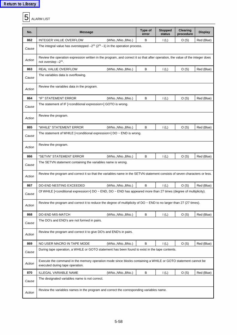
5 ALARM LIST
5-58
No. Message Type oferror
Stoppedstatus
Clearingprocedure
Display
862 INTEGER VALUE OVERFLOW (WNo.,NNo.,BNo.) B I (L) O (S) Red (Blue)
CauseThe integral value has overstepped –231 (231 –1) in the operation process.
ActionReview the operation expression written in the program, and correct it so that after operation, the value of the integer doesnot overstep –231.
863 REAL VALUE OVERFLOW (WNo.,NNo.,BNo.) B I (L) O (S) Red (Blue)
CauseThe variables data is overflowing.
ActionReview the variables data in the program.
864 “IF” STATEMENT ERROR (WNo.,NNo.,BNo.) B I (L) O (S) Red (Blue)
CauseThe statement of IF [<conditional expression>] GOTO is wrong.
ActionReview the program.
865 “WHILE” STATEMENT ERROR (WNo.,NNo.,BNo.) B I (L) O (S) Red (Blue)
CauseThe statement of WHILE [<conditional expression>] DO ~ END is wrong.
ActionReview the program.
866 “SETVN” STATEMENT ERROR (WNo.,NNo.,BNo.) B I (L) O (S) Red (Blue)
CauseThe SETVN statement containing the variables name is wrong.
ActionReview the program and correct it so that the variables name in the SETVN statement consists of seven characters or less.
867 DO-END NESTING EXCEEDED (WNo.,NNo.,BNo.) B I (L) O (S) Red (Blue)
CauseOf WHILE [<conditional expression>] DO ~ END, DO ~ END has appeared more than 27 times (degree of multiplicity).
ActionReview the program and correct it to reduce the degree of multiplicity of DO ~ END to no larger than 27 (27 times).
868 DO-END MIS-MATCH (WNo.,NNo.,BNo.) B I (L) O (S) Red (Blue)
CauseThe DO's and END's are not formed in pairs.
ActionReview the program and correct it to give DO's and END's in pairs.
869 NO USER MACRO IN TAPE MODE (WNo.,NNo.,BNo.) B I (L) O (S) Red (Blue)
CauseDuring tape operation, a WHILE or GOTO statement has been found to exist in the tape contents.
ActionExecute the command in the memory operation mode since blocks containing a WHILE or GOTO statement cannot beexecuted during tape operation.
870 ILLEGAL VARIABLE NAME (WNo.,NNo.,BNo.) B I (L) O (S) Red (Blue)
CauseThe designated variables name is not correct.
ActionReview the variables names in the program and correct the corresponding variables name.

ALARM LIST 5
5-59
No. Message Type oferror
Stoppedstatus
Clearingprocedure
Display
871 VARIABLE NAME EXISTS (WNo.,NNo.,BNo.) B I (L) O (S) Red (Blue)
CauseThere are overlapping variables names.
ActionCorrect the program so that variables names do not overlap.
872 G51 OPTION NOT FOUND (WNo.,NNo.,BNo.) B I (L) O (S) Red (Blue)
CauseA scaling command (G50 or G51) has been designated although scaling specifications are not provided.
ActionCheck the specifications.
873 G51.1 OPTION NOT FOUND (WNo.,NNo.,BNo.) B I (L) O (S) Red (Blue)
CauseA mirror image command (G50.1 or G51.1) has been designated although programmable mirror image specifications arenot provided.
ActionCheck the specifications.
874 CORNER R/C OPTION NOT FOUND (WNo.,NNo.,BNo.) B I (L) O (S) Red (Blue)
CauseCorner chamfering or corner rounding Ι/ΙΙ has been designated although such specifications are not provided.
ActionCheck the specifications and delete corner rounding or corner chamfering from the program.
875 NOT FOUND GEOMETRIC OPTION (WNo.,NNo.,BNo.) B I (L) O (S) Red (Blue)
CauseThe geometric command has been designated although geometric specifications are not provided.
ActionCheck the specifications.
876 NOT FOUND GEOMETRIC OPTION (WNo.,NNo.,BNo.) B I (L) O (S) Red (Blue)
CauseThe geometrics setting format is wrong.
ActionReview the program.
877 G15 OPTION NOT FOUND (WNo.,NNo.,BNo.) B I (L) O (S) Red (Blue)
CauseThe polar coordinates command (G16) has been designated although such command specifications are not provided.
ActionCheck the specifications.
878 ADDRESS CHANGE OPTION NOT FOUND (WNo.,NNo.,BNo.) B I (L) O (S) Red (Blue)
CauseAbsolute/incremental axis address conversion has been designated although such conversion specifications are notprovided.
ActionCheck the specifications.
879 G10 OPTION NOT FOUND (WNo.,NNo.,BNo.) B I (L) O (S) Red (Blue)
CauseProgram data input has been designated although such input specifications are not provided.
ActionCheck the specifications.

5 ALARM LIST
5-60
No. Message Type oferror
Stoppedstatus
Clearingprocedure
Display
880 AXIS NOT ZERO RETURNED (WNo.,NNo.,BNo.) B I (L) O (S) Red (Blue)
CauseA move command other than that for reference-point return has been designated for the axis that was not returned to itsreference point.
ActionManually return the axis to its reference point.
881 G30 OPTION NOT FOUND (WNo.,NNo.,BNo.) B I (L) O (S) Red (Blue)
CauseSecond, third or fourth reference-point return has been designated although such reference-point returning specificationsare not provided.
ActionCheck the specifications.
882 —— ( , , )
Cause ——
Action ——
883 —— ( , , )
Cause ——
Action ——
884 REFERENCE POINT RETURN CHECK (WNo.,NNo.,BNo.) B I (L) O (S) Red (Blue)
CauseAn axis had not returned to the zero-point when the zero-point check command (G27) was executed.
ActionReview the program.
885 G22 OPTION NOT FOUND (WNo.,NNo.,BNo.) B I (L) O (S) Red (Blue)
CauseThe before-movement stroke check function (G22) has been designated although such function specifications are notprovided.
ActionCheck the specifications.
886 BEYOND AREA OF G22 (WNo.,NNo.,BNo.) B I (L) O (S) Red (Blue)
CauseThis alarm message is displayed before execution of a movement block to indicate that the ending point of the axismovement designated in the block is likely to enter the forbidden area which has been designated using the before-movement stroke check function (G22).
ActionReview the axis-address coordinate values in the program.
887 TAPE I/O ERROR (WNo.,NNo.,BNo.) B (G) I O Red (Blue)
Cause1. Errors have occurred in the tape reader or printer errors have occurred during macroprogram data printing.
2. Host computer program used for Ethernet operation has failed.
Action1. Check for parameter errors.
2. Check for improper connection between the host computer containing the designated program, and the NC unit.
888 FILE I/O ERROR ( , , ) E I O Red (Blue)
CauseThe machining program file cannot be read.
ActionPlease contact your YAMAZAKI MAZAK products service station.

ALARM LIST 5
5-61
No. Message Type oferror
Stoppedstatus
Clearingprocedure
Display
889 G37 OPTION NOT FOUND (WNo.,NNo.,BNo.) B I (L) O (S) Red (Blue)
CauseThe automatic tool-length measurement command (G37) has been designated although such measurement specificationsare not provided.
ActionCheck the specifications.
890 G31 OPTION NOT FOUND (WNo.,NNo.,BNo.) B I (L) O (S) Red (Blue)
CauseThe skip command (G31) has been designated although skip specifications are not provided.
ActionCheck the specifications.
891 G31.1 - G31.3 OPTION NOT FOUND (WNo.,NNo.,BNo.) B I (L) O (S) Red (Blue)
CauseA multi-step skip command (G31.1, G31.2 or G31.3) has been designated although such skip specifications are notprovided.
ActionCheck the specifications.
892 AUTO PROGRAMMING FAILURE (WNo.,NNo.,BNo.) B I (L) O (S) Red (Blue)
CauseA trouble has occurred with the software of auto program during the operation.
ActionPlease contact your YAMAZAKI MAZAK products service station.
893 PROGRAM DATA MISSING ( , , ) B I (L) O (S) Red (Blue)
CauseArgument P was not designated in the macro call command (G65, G66, G66.1).
ActionReview the program and set the number of the macro program to be called to argument P.
894 MAZATROL PROGRAM DESIGNATED ( , , ) B I (L) O (S) Red (Blue)
Cause
1. An attempt has been made to call a MAZATROL program from an EIA/ISO program which was designated as asubprogram of MAZATROL program.
2. A MAZATROL program has been specified using G65 command (subprogram call) in the manual program mode unit ofthe MAZATROL program.
ActionIn cases 1 and 2 above, a MAZATROL program cannot be called as a subprogram. Review the program.
895 IC CARD I/O BUSY ( , , ) A I O Red
CauseAn attempt has been made to execute the IC memory card operation during data I/O operation with an IC memory card.
ActionExecute the IC memory card operation after stop or completion of the data I/O operation with an IC memory card.
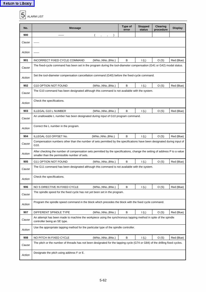
5 ALARM LIST
5-62
No. Message Type oferror
Stoppedstatus
Clearingprocedure
Display
900 —— ( , , )
Cause ——
Action ——
901 INCORRECT FIXED CYCLE COMMAND (WNo.,NNo.,BNo.) B I (L) O (S) Red (Blue)
CauseThe fixed-cycle command has been set in the program during the tool-diameter compensation (G41 or G42) modal status.
ActionSet the tool-diameter compensation cancellation command (G40) before the fixed-cycle command.
902 G10 OPTION NOT FOUND (WNo.,NNo.,BNo.) B I (L) O (S) Red (Blue)
CauseThe G10 command has been designated although this command is not available with the system.
ActionCheck the specifications.
903 ILLEGAL G10 L NUMBER (WNo.,NNo.,BNo.) B I (L) O (S) Red (Blue)
CauseAn unallowable L number has been designated during input of G10 program command.
ActionCorrect the L number in the program.
904 ILLEGAL G10 OFFSET No. (WNo.,NNo.,BNo.) B I (L) O (S) Red (Blue)
CauseCompensation numbers other than the number of sets permitted by the specifications have been designated during input ofG10.
ActionAfter checking the number of compensation sets permitted by the specifications, change the setting of address P to a valuesmaller than the permissible number of sets.
905 G11 OPTION NOT FOUND (WNo.,NNo.,BNo.) B I (L) O (S) Red (Blue)
CauseThe G11 command has been designated although this command is not available with the system.
ActionCheck the specifications.
906 NO S DIRECTIVE IN FIXED CYCLE (WNo.,NNo.,BNo.) B I (L) O (S) Red (Blue)
CauseThe spindle speed for the fixed cycle has not yet been set in the program.
ActionProgram the spindle speed command in the block which precedes the block with the fixed cycle command.
907 DIFFERENT SPINDLE TYPE (WNo.,NNo.,BNo.) B I (L) O (S) Red (Blue)
CauseAn attempt has been made to machine the workpiece using the synchronous tapping method in spite of the spindlecontroller being an SE type.
ActionUse the appropriate tapping method for the particular type of the spindle controller.
908 NO PITCH IN FIXED CYCLE (WNo.,NNo.,BNo.) B I (L) O (S) Red (Blue)
CauseThe pitch or the number of threads has not been designated for the tapping cycle (G74 or G84) of the drilling fixed cycles.
ActionDesignate the pitch using address F or E.
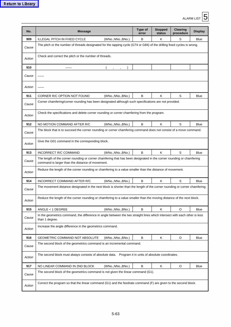
ALARM LIST 5
5-63
No. Message Type oferror
Stoppedstatus
Clearingprocedure
Display
909 ILLEGAL PITCH IN FIXED CYCLE (WNo.,NNo.,BNo.) B K S Blue
CauseThe pitch or the number of threads designated for the tapping cycle (G74 or G84) of the drilling fixed cycles is wrong.
ActionCheck and correct the pitch or the number of threads.
910 —— ( , , )
Cause ——
Action ——
911 CORNER R/C OPTION NOT FOUND (WNo.,NNo.,BNo.) B K S Blue
CauseCorner chamfering/corner rounding has been designated although such specifications are not provided.
ActionCheck the specifications and delete corner rounding or corner chamfering from the program.
912 NO MOTION COMMAND AFTER R/C (WNo.,NNo.,BNo.) B K S Blue
CauseThe block that is to succeed the corner rounding or corner chamfering command does not consist of a move command.
ActionGive the G01 command in the corresponding block.
913 INCORRECT R/C COMMAND (WNo.,NNo.,BNo.) B K S Blue
CauseThe length of the corner rounding or corner chamfering that has been designated in the corner rounding or chamferingcommand is larger than the distance of movement.
ActionReduce the length of the corner rounding or chamfering to a value smaller than the distance of movement.
914 INCORRECT COMMAND AFTER R/C (WNo.,NNo.,BNo.) B K S Blue
CauseThe movement distance designated in the next block is shorter than the length of the corner rounding or corner chamfering.
ActionReduce the length of the corner rounding or chamfering to a value smaller than the moving distance of the next block.
915 ANGLE < 1 DEGREE (WNo.,NNo.,BNo.) B K O Blue
CauseIn the geometrics command, the difference in angle between the two straight lines which intersect with each other is lessthan 1 degree.
ActionIncrease the angle difference in the geometrics command.
916 GEOMETRIC COMMAND NOT ABSOLUTE (WNo.,NNo.,BNo.) B K O Blue
CauseThe second block of the geometrics command is an incremental command.
ActionThe second block must always consists of absolute data. Program it in units of absolute coordinates.
917 NO LINEAR COMMAND IN 2ND BLOCK (WNo.,NNo.,BNo.) B K O Blue
CauseThe second block of the geometrics command is not given the linear command (G1).
ActionCorrect the program so that the linear command (G1) and the feedrate command (F) are given to the second block.

5 ALARM LIST
5-64
No. Message Type oferror
Stoppedstatus
Clearingprocedure
Display
918 INCORRECT ANGLE DATA (WNo.,NNo.,BNo.) B I (L) O (S) Red (Blue)
CauseIn address designation of the geometrics command, the angle in the first block, ending point coordinates and angle in thesecond block are incorrectly given.
ActionCheck and reprogram the corresponding data.
919 INCORRECT PLANE SELECTION CMD. (WNo.,NNo.,BNo.) B I (L) O (S) Red (Blue)
CauseA plane selection command (G17, G18 or G19) was given in the geometrics command block.
ActionProgram the plane selection command (G17, G18 or G19) in the block that precedes the geometrics command block.
920 G27, M COMMANDS SAME BLOCK (WNo.,NNo.,BNo.) B I (L) O (S) Red (Blue)
CauseAn M independent command (M0, M1, M2 or M30) has been programmed in the same block as the G27 command.
ActionCorrect the program so that the G27 command and the M independent command are contained in separate blocks.
921 G29, M COMMANDS SAME BLOCK (WNo.,NNo.,BNo.) B I (L) O (S) Red (Blue)
CauseAn M independent command (M0, M1, M2 or M30) and the G29 command (start-position return) have been programmed inthe same block.
ActionCorrect the program so that the G29 command and the M independent command are contained in separate blocks.
922 SKIP SPEED ZERO (WNo.,NNo.,BNo.) B I (L) O (S) Red (Blue)
CauseThe feedrate F has not been programmed in the G31 (skip) command block.
ActionSet the skip feedrate F into the G31 program block.
923 ILLEGAL COMMAND G37 AXIS (WNo.,NNo.,BNo.) B I (L) O (S) Red (Blue)
CauseNo axis settings are included in the automatic tool-length measurement block; or more than one axis setting have beenmade.
ActionDesignate only one axis.
924 G37, H COMMANDS SAME BLOCK (WNo.,NNo.,BNo.) B I (L) O (S) Red (Blue)
CauseThe H code is in the same block as the automatic tool-length measurement command.
ActionSet the H code into a block preceeding the automatic tool-length measurement block.
925 H CODE REQUIRED (WNo.,NNo.,BNo.) B I (L) O (S) Red (Blue)
CauseThe H code is not yet set for automatic tool-length measurement.
ActionSet an H code into a block preceeding the automatic tool-length measurement block.
926 ILLEGAL G37 SIGNAL (WNo.,NNo.,BNo.) B I O Red
CauseThe signal of measuring-position arrival has been turned on before the tool reaches the area designated through either a Dcode or the parameter for deceleration area “d”; or the signal has not been turned on at all.
ActionCheck the program and parameters.

ALARM LIST 5
5-65
No. Message Type oferror
Stoppedstatus
Clearingprocedure
Display
927 SKIP COMMAND IN CORRECTING DIA (WNo.,NNo.,BNo.) B I (L) O (S) Red (Blue)
CauseThe skip command (G31) was given during tool-diameter compensation (G41 or G42).
ActionCorrect the program so that the skip command is executed only after the cutter-diameter compensation cancellationcommand (G40) has been executed.
928 ILLEGAL HEAD DATA No. (WNo.,NNo.,BNo.) B I (L) O (S) Red (Blue)
CauseThe offset number that has been designated in the program is outside the range from 0 to 10.
ActionReview the machining program and set an allowable offset number.
929 HEAD DATA No. NOT FOUND (WNo.,NNo.,BNo.) B I (L) O (S) Red (Blue)
CauseAn “H_” number is missing in the “G45.1H_” part of the EIA/ISO program.
ActionReview the machining program and set an allowable offset number.
930 ILLEGAL HEAD TYPE (WNo.,NNo.,BNo.) B I (L) O (S) Red (Blue)
CauseThe head type does not match to the face that has been designated in the program.
ActionReview the machining program and set the correct head type.
931 NO HEAD DATA (WNo.,NNo.,BNo.) B I (L) O (S) Red (Blue)
CauseThe head number that has been designated in the program is not registered on the HEAD OFFSET display.
Action1. Review the designated head number.
2. Check if the designated head number is registered on the HEAD OFFSET display.
932 RETURN R POINT IN CUTTING SIDE (WNo.,NNo.,BNo.) B I (L) O (S) Red (Blue)
CauseReturn to reference point has been designated during the side-machining mode (G17.2 to G17.5) of the program.
ActionReturn to reference point cannot be executed during the side-machining mode (G17.2 to G17.5). Review the cuttingprogram.
933 NO 5FACE CUTTING OPTION (WNo.,NNo.,BNo.) B I (L) O (S) Red (Blue)
CauseAn attempt has been made to execute a five-surface machining program when the five-surface machining option was notpresent.
ActionSet the five-surface machining option to execute a five-surface machining program.
934 NO HIGH-SPEED MODE OPTION (WNo.,NNo.,BNo.) B I (L) O (S) Red (Blue)
CauseAn attempt has been made to execute the high-speed mode program when the high-speed mode option was not set.
ActionWithout the high-speed mode option, the high-speed mode program cannot be executed.
935 NO PRE-INTERP ACCEL/DECEL OPT. (WNo.,NNo.,BNo.) B I (L) O (S) Red (Blue)
CauseAn attempt has been made to execute the high-accuracy mode program when the high-accuracy mode option was not set.
ActionWithout the high-accuracy mode option, the high-accuracy mode program cannot be executed.

5 ALARM LIST
5-66
No. Message Type oferror
Stoppedstatus
Clearingprocedure
Display
936 OPTION NOT FOUND (WNo., 0, 0) E I (L) O Red
Cause
Either of the following five options is missing (identify the corresponding option from the work number specified in theargument corresponding to the alarm):
1. NURBS interpolation option2. Shaping option3. Planet tapping option4. MAZAK precision rapid boring tornado option or shape correction control option5. Ethernet operation
ActionCheck the specifications.
937 ILLEGAL TOOL DESIGNATED (WNo.,NNo.,BNo.) B I (L) O (S) Red (Blue)
CauseThe designated tool cannot be used.
ActionCheck the TOOL DATA display to see if the designated tool is an unusable one.
938 NO IC CARD MODE OPTION ( , , ) A K P Red
CauseAn attempt has been made to execute the IC memory card operation although the optional function of IC memory cardoperation is not available.
ActionThis operation cannot be executed because the optional function of IC memory card operation is not available.
939 NO THREAD CUTTING OPTION (WNo.,NNo.,BNo.) A (A) K (L) P (S) Red (Blue)
CauseAn attempt has been made to execute operation or tool path check of the program that contains G33 command (threading),although G33 option is not provided.
ActionWithout G33 option, G33 threading command cannot be used.
940 NO INVERSE TIME OPTION (WNo.,NNo.,BNo.) B I (L) O (S) Red (Blue)
CauseInverse time feed program was attempted although inverse time feed option is not provided.
ActionInverse time feed program cannot be executed because inverse time feed option is not provided.
941 G93 MODE (WNo.,NNo.,BNo.) B I (L) O (S) Red (Blue)
CauseG code of inhibition during G93 mode has been designated.
ActionReview the program and delete G code of inhibition.
942 NO 3-D CONVERSION OPTION (WNo.,NNo.,BNo.) B I (L) O (S) Red (Blue)
CauseAn attempt has been made to execute the three-dimensional coordinate conversion program in the absence of a three-dimensional coordinate conversion option.
Action
Three-dimensional coordinate conversion is not possible because of the absence of a three-dimensional coordinateconversion option.
<HV>
943 CONVERTING IN 3-D COORDINATES (WNo.,NNo.,BNo.) B I (L) O (S) Red (Blue)
CauseAn illegal G-code in the G68 mode has been designated.
ActionReview the program, and delete the illegal G-code.
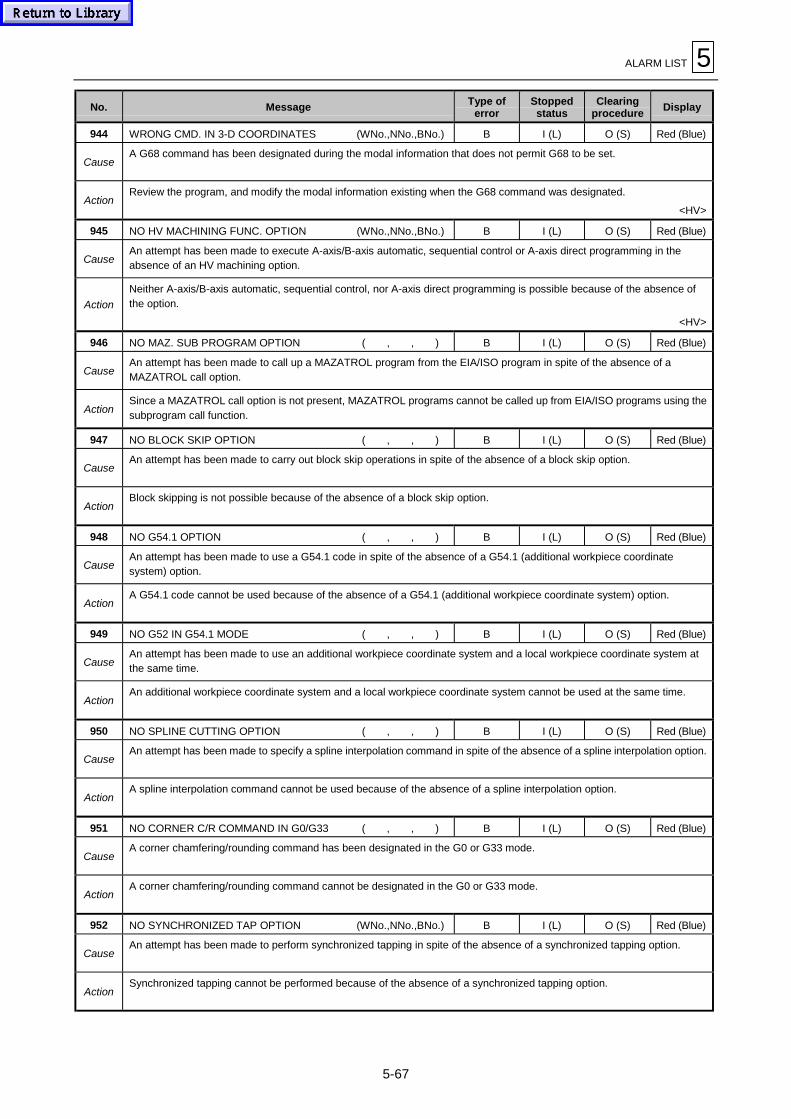
ALARM LIST 5
5-67
No. Message Type oferror
Stoppedstatus
Clearingprocedure
Display
944 WRONG CMD. IN 3-D COORDINATES (WNo.,NNo.,BNo.) B I (L) O (S) Red (Blue)
CauseA G68 command has been designated during the modal information that does not permit G68 to be set.
ActionReview the program, and modify the modal information existing when the G68 command was designated.
<HV>
945 NO HV MACHINING FUNC. OPTION (WNo.,NNo.,BNo.) B I (L) O (S) Red (Blue)
CauseAn attempt has been made to execute A-axis/B-axis automatic, sequential control or A-axis direct programming in theabsence of an HV machining option.
Action
Neither A-axis/B-axis automatic, sequential control, nor A-axis direct programming is possible because of the absence ofthe option.
<HV>
946 NO MAZ. SUB PROGRAM OPTION ( , , ) B I (L) O (S) Red (Blue)
CauseAn attempt has been made to call up a MAZATROL program from the EIA/ISO program in spite of the absence of aMAZATROL call option.
ActionSince a MAZATROL call option is not present, MAZATROL programs cannot be called up from EIA/ISO programs using thesubprogram call function.
947 NO BLOCK SKIP OPTION ( , , ) B I (L) O (S) Red (Blue)
CauseAn attempt has been made to carry out block skip operations in spite of the absence of a block skip option.
ActionBlock skipping is not possible because of the absence of a block skip option.
948 NO G54.1 OPTION ( , , ) B I (L) O (S) Red (Blue)
CauseAn attempt has been made to use a G54.1 code in spite of the absence of a G54.1 (additional workpiece coordinatesystem) option.
ActionA G54.1 code cannot be used because of the absence of a G54.1 (additional workpiece coordinate system) option.
949 NO G52 IN G54.1 MODE ( , , ) B I (L) O (S) Red (Blue)
CauseAn attempt has been made to use an additional workpiece coordinate system and a local workpiece coordinate system atthe same time.
ActionAn additional workpiece coordinate system and a local workpiece coordinate system cannot be used at the same time.
950 NO SPLINE CUTTING OPTION ( , , ) B I (L) O (S) Red (Blue)
CauseAn attempt has been made to specify a spline interpolation command in spite of the absence of a spline interpolation option.
ActionA spline interpolation command cannot be used because of the absence of a spline interpolation option.
951 NO CORNER C/R COMMAND IN G0/G33 ( , , ) B I (L) O (S) Red (Blue)
CauseA corner chamfering/rounding command has been designated in the G0 or G33 mode.
ActionA corner chamfering/rounding command cannot be designated in the G0 or G33 mode.
952 NO SYNCHRONIZED TAP OPTION (WNo.,NNo.,BNo.) B I (L) O (S) Red (Blue)
CauseAn attempt has been made to perform synchronized tapping in spite of the absence of a synchronized tapping option.
ActionSynchronized tapping cannot be performed because of the absence of a synchronized tapping option.

5 ALARM LIST
5-68
No. Message Type oferror
Stoppedstatus
Clearingprocedure
Display
953 TOOL DATA INPUT PROCESS ERROR ( , , ) B I (L) O (S) Red (Blue)
CauseDuring the execution of EIA/ISO program or of MDI, the tool data was found not to include “LENGTH” or “ACT-φ (NOM-φ)”(this, however, applies only if bit 7 of parameter F84 is set to “1” for the use of MAZATROL tool length and tool diameterdata).
ActionRecheck the tool data and set missing values. (Related parameters: F84-7, F92-7, F93-3)
954 SCREW PITCH ERR ( , , ) B I (L) O (S) Red (Blue)
CauseThe thread lead (thread pitch) that has been designated in the threading command data is not correct.
ActionSet the correct thread lead in the threading command data.
955 START AND END POINT NOT AGREE (WNo.,NNo.,BNo.) E I (L) O Red
CauseThe ending point of the block immediately preceding the G06.2 command data, and the command data in the starting blockof G06.2 do not match.
ActionModify the program so that the coordinate command data in the starting block of G06.2 matches the ending point of theimmediately preceding block.
956 RESTART OPERATION NOT ALLOWED (WNo.,NNo.,BNo.) E I (L) O Red
CauseRestarting from the block containing the G06.2 mode data has been attempted.
ActionRestart from a block not containing G06.2 mode data.
957 MANUAL INTERRUPT NOT ALLOWED (WNo.,NNo.,BNo.) E I (L) O Red
CauseManual handle or MDI interruption from the block containing the G06.2 mode data has been attempted.
ActionPerform manual interruptions only at blocks not containing G06.2 mode data.
958 AUTO PECKING IMPOSSIBLE (WNo.,NNo.,BNo.) E I O Red
Cause1. The threshold value for load detection-based auto-pecking is not set to 0 or no such value is set.
2. The parameter is not set appropriately.
Action
1. Set the appropriate threshold value either in the drill monitoring mode of the MACHINING-MONITORING display or onthe TOOL DATA display.
2. For parameter setting, please contact the Mazak service representative in your area.
979 MACRO USER ALARM ( , , ) B I (L) O (S) Red (Blue)
Cause#3000 = n (alarm message) in the user macroprogram was executed. (n ≥ 21)
ActionRefer to the relevant user macroprogram instruction manual to check the alarm.
980 MACRO USER ALARM 1 ( , , ) B I (L) O (S) Red (Blue)
Cause#3000 = 1 (alarm message) in the user macroprogram was executed.
ActionRefer to the relevant user macroprogram instruction manual to check the alarm.
981 MACRO USER ALARM 2 ( , , ) B I (L) O (S) Red (Blue)
Cause#3000 = 2 (alarm message) in the user macroprogram was executed.
ActionRefer to the relevant user macroprogram instruction manual to check the alarm.
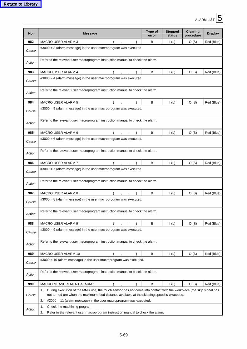
ALARM LIST 5
5-69
No. Message Type oferror
Stoppedstatus
Clearingprocedure
Display
982 MACRO USER ALARM 3 ( , , ) B I (L) O (S) Red (Blue)
Cause#3000 = 3 (alarm message) in the user macroprogram was executed.
ActionRefer to the relevant user macroprogram instruction manual to check the alarm.
983 MACRO USER ALARM 4 ( , , ) B I (L) O (S) Red (Blue)
Cause#3000 = 4 (alarm message) in the user macroprogram was executed.
ActionRefer to the relevant user macroprogram instruction manual to check the alarm.
984 MACRO USER ALARM 5 ( , , ) B I (L) O (S) Red (Blue)
Cause#3000 = 5 (alarm message) in the user macroprogram was executed.
ActionRefer to the relevant user macroprogram instruction manual to check the alarm.
985 MACRO USER ALARM 6 ( , , ) B I (L) O (S) Red (Blue)
Cause#3000 = 6 (alarm message) in the user macroprogram was executed.
ActionRefer to the relevant user macroprogram instruction manual to check the alarm.
986 MACRO USER ALARM 7 ( , , ) B I (L) O (S) Red (Blue)
Cause#3000 = 7 (alarm message) in the user macroprogram was executed.
ActionRefer to the relevant user macroprogram instruction manual to check the alarm.
987 MACRO USER ALARM 8 ( , , ) B I (L) O (S) Red (Blue)
Cause#3000 = 8 (alarm message) in the user macroprogram was executed.
ActionRefer to the relevant user macroprogram instruction manual to check the alarm.
988 MACRO USER ALARM 9 ( , , ) B I (L) O (S) Red (Blue)
Cause#3000 = 9 (alarm message) in the user macroprogram was executed.
ActionRefer to the relevant user macroprogram instruction manual to check the alarm.
989 MACRO USER ALARM 10 ( , , ) B I (L) O (S) Red (Blue)
Cause#3000 = 10 (alarm message) in the user macroprogram was executed.
ActionRefer to the relevant user macroprogram instruction manual to check the alarm.
990 MACRO MEASUREMENT ALARM 1 ( , , ) B I (L) O (S) Red (Blue)
Cause
1. During execution of the MMS unit, the touch sensor has not come into contact with the workpiece (the skip signal hasnot turned on) when the maximum feed distance available at the skipping speed is exceeded.
2. #3000 = 11 (alarm message) in the user macroprogram was executed.
Action1. Check the machining program.
2. Refer to the relevant user macroprogram instruction manual to check the alarm.

5 ALARM LIST
5-70
No. Message Type oferror
Stoppedstatus
Clearingprocedure
Display
991 MACRO MEASUREMENT ALARM 2 ( , , ) B I (L) O (S) Red (Blue)
Cause
1. During execution of the MMS unit, the touch sensor came into contact with the workpiece (the skip signal turned on)when another feeding than that at the skipping speed was taking place.
2. #3000 = 12 (alarm message) in the user macroprogram was executed.
Action1. Check the machining program. Also check the touch sensor for proper mounting on the spindle.
2. Refer to the relevant user macroprogram instruction manual to check the alarm.
992 MACRO MEASUREMENT ALARM 3 ( , , ) B I (L) O (S) Red (Blue)
Cause
1. Correct signals were not output because of trouble with the touch sensors, receivers or other such MMS unitcomponents.
2. #3000 = 13 (alarm message) in the user macroprogram was executed.
Action1. Contact a service station.
2. Refer to the relevant user macroprogram instruction manual to check the alarm.
993 MACRO MEASUREMENT ALARM 4 ( , , ) B I (L) O (S) Red (Blue)
Cause#3000 = 14 (alarm message) in the user macroprogram was executed.
ActionRefer to the relevant user macroprogram instruction manual to check the alarm.
994 MACRO MEASUREMENT ALARM 5 ( , , ) B I (L) O (S) Red (Blue)
Cause#3000 = 15 (alarm message) in the user macroprogram was executed.
ActionRefer to the relevant user macroprogram instruction manual to check the alarm.
995 MACRO MEASUREMENT ALARM 6 ( , , ) B I (L) O (S) Red (Blue)
Cause#3000 = 16 (alarm message) in the user macroprogram was executed.
ActionRefer to the relevant user macroprogram instruction manual to check the alarm.
996 MACRO MEASUREMENT ALARM 7 ( , , ) B I (L) O (S) Red (Blue)
Cause#3000 = 17 (alarm message) in the user macroprogram was executed.
ActionRefer to the relevant user macroprogram instruction manual to check the alarm.
997 MACRO MEASUREMENT ALARM 8 ( , , ) B I (L) O (S) Red (Blue)
Cause#3000 = 18 (alarm message) in the user macroprogram was executed.
ActionRefer to the relevant user macroprogram instruction manual to check the alarm.
998 MACRO MEASUREMENT ALARM 9 ( , , ) B I (L) O (S) Red (Blue)
Cause#3000 = 19 (alarm message) in the user macroprogram was executed.
ActionRefer to the relevant user macroprogram instruction manual to check the alarm.
999 MACRO MEASUREMENT ALARM 10 ( , , ) B I (L) O (S) Red (Blue)
Cause#3000 = 20 (alarm message) in the user macroprogram was executed.
ActionRefer to the relevant user macroprogram instruction manual to check the alarm.
EE