
MAURER Girder Grid Joints
12
MAURER Girder Grid Joints
-
Upload
briankimbj -
Category
Documents
-
view
28 -
download
0
description
MAURER Movement Joints
Transcript of MAURER Girder Grid Joints

MAURER Girder Grid Joints
MAURER Modular Expansion Joints
Expansion joints have the task of bridging structural gaps by com– plying with the following require-ments:
1. Accommodation of loads and movements by
safe transmission of traffic loads rigid and shallow anchorage in
the structural components low detriment to carriageway
surface continuous adaption to
deformations in the structure low resistance to deformation
2. Durability of joint system and its adjoining components due to
absolute watertightness high fatigue strength resilience, i.e. unrestrained and
damped support of all movable components
use of materials resistant to aging, corrosion and wear
maintenance-free design 3. Low noise emission under traffic due to
avoidance of surface irregularities
sealing elements, which are not subjected to traffic loads
preloaded bearing components made of high-grade synthetics.
4. Efficiency
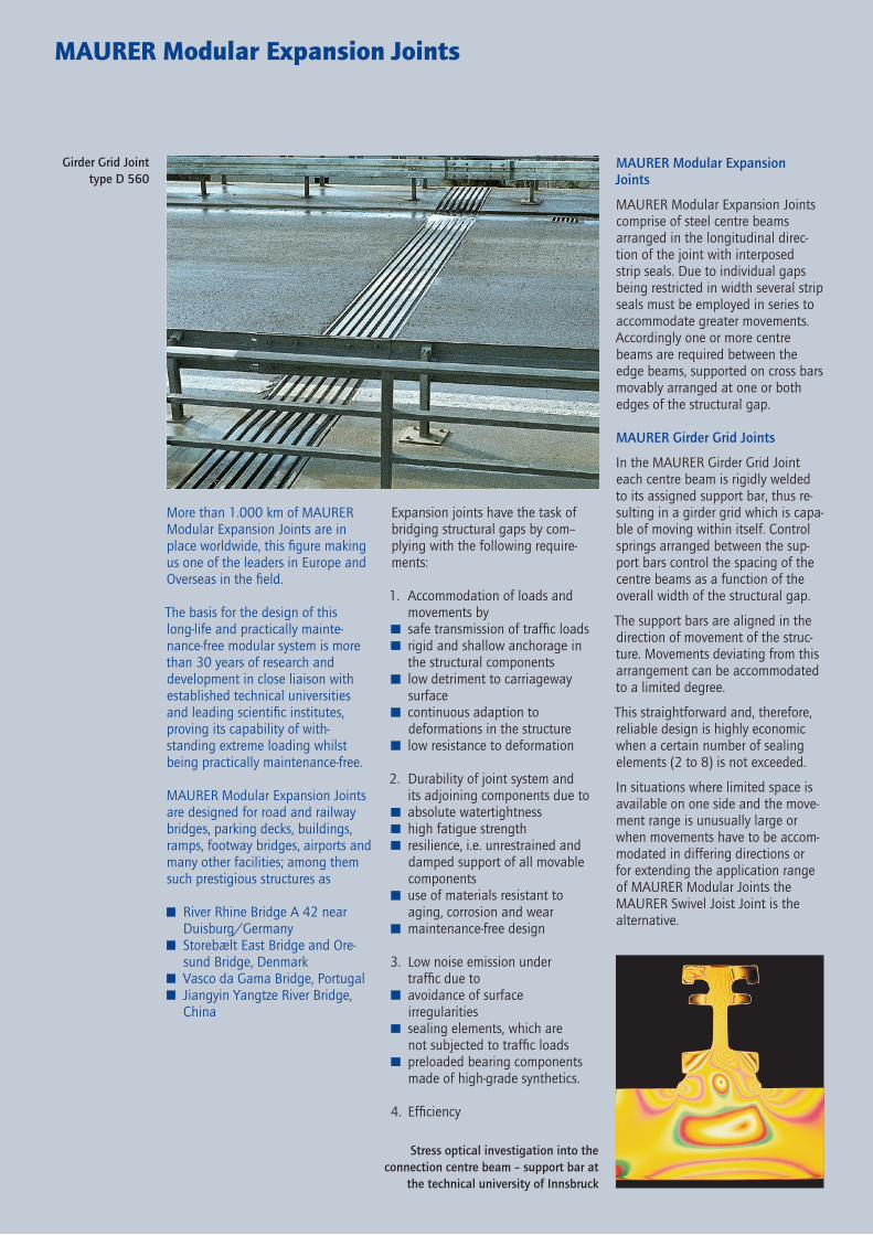
Girder Grid Joint type D 560
Stress optical investigation into the connection centre beam – support bar at
the technical university of Innsbruck
MAURER Modular Expansion Joints
MAURER Modular Expansion Joints comprise of steel centre beams arranged in the longitudinal direc-tion of the joint with interposed strip seals. Due to individual gaps being restricted in width several strip seals must be employed in series to accommodate greater movements. Accordingly one or more centre beams are required between the edge beams, supported on cross bars movably arranged at one or both edges of the structural gap.
MAURER Girder Grid Joints
In the MAURER Girder Grid Joint each centre beam is rigidly welded to its assigned support bar, thus re-sulting in a girder grid which is capa-ble of moving within itself. Control springs arranged between the sup-port bars control the spacing of the centre beams as a function of the overall width of the structural gap.
The support bars are aligned in the direction of movement of the struc-ture. Movements deviating from this arrangement can be accommodated to a limited degree.
This straightforward and, therefore, reliable design is highly economic when a certain number of sealing elements (2 to 8) is not exceeded.
In situations where limited space is available on one side and the move-ment range is unusually large or when movements have to be accom-modated in differing directions or for extending the application range of MAURER Modular Joints the MAURER Swivel Joist Joint is the alternative.
More than 1.000 km of MAURER Modular Expansion Joints are in place worldwide, this figure making us one of the leaders in Europe and Overseas in the field.
The basis for the design of this long-life and practically mainte-nance-free modular system is more than 30 years of research and development in close liaison with established technical universities and leading scientific institutes, proving its capability of with-standing extreme loading whilst being practically maintenance-free.
MAURER Modular Expansion Joints are designed for road and railway bridges, parking decks, buildings, ramps, footway bridges, airports and many other facilities; among them such prestigious structures as
River Rhine Bridge A 42 near Duisburg/Germany
Storebælt East Bridge and Ore-sund Bridge, Denmark
Vasco da Gama Bridge, Portugal Jiangyin Yangtze River Bridge,
China

8
10
9
113
76
54
21
Designation Description
Supporting Elements
1 Edge Beam Hot-rolled section of steel grade S 235 JR G2 precision tolerances combining good weldability with notch toughness. Can be both shop and site butt-welded.
2 Centre Beam Hot-rolled section of steel grade S 355 J2 G3 precision tolerances combining good weldability with notch tough ness. Can be both shop and site butt-welded by patented system.
3 Support Bar Steel grade S 355 J2 G3, machined for precision tolerances.
Supports
4 Sliding Plate Stainless steel in bridge bearing quality. Sliding surfaces ground and polished. Material no. 1.4401.
5 Sliding Spring Natural rubber steel laminated, vulcanized in place. Sliding surfaces of PTFE.
6 Sliding Bearing Chloroprene rubber with steel spherical inlay vulcanized in place to handle tilt loading. Sliding surfaces of PTFE.
Control Elements
7 Control Spring Cellular polyurethane of high tear strength, insensitive to oil, gasoline, ozone. High resistance to aging, high self-damping.
Sealing Elements
8 Strip Seal 80 Chloroprene rubber or EPDM with high tear strength, resistant to salt water, oil and aging, available in any length. Can be vulcanized in place on site.
Anchorage
9 Carriageway Anchor Steel plate and loop from S 235 JR G2.
10 Anchor Stud St 37K
11 Support Box To accommodate the sliding bearings, sliding springs, control springs and support bars.
Design Principles and Main Components
Technical approval and independent periodical inspection acc. to TL/TP-FÜ
Continuous in-house and field qual-ity control, the use of high-grade materials and a quality assurance system in keeping with ISO 9001 and EN 29001 ensure the high stan-dard of MAURER Girder Grid Joints.
All design elements of MAURER expansion joints are engineered in high-quality materials. All synthetics used feature excellent resistance to aging, wear and the environment. Relaxation of the control and bear-ing elements is insignificant even after decades of service. The sealing elements are insensitive to physical stress.
National regulations are to be taken into account in the choice of the cor-rosion protection system. We recom-mend using two-part zinc-rich paint as the primer and epoxy-based mica-ceous iron as the finish.
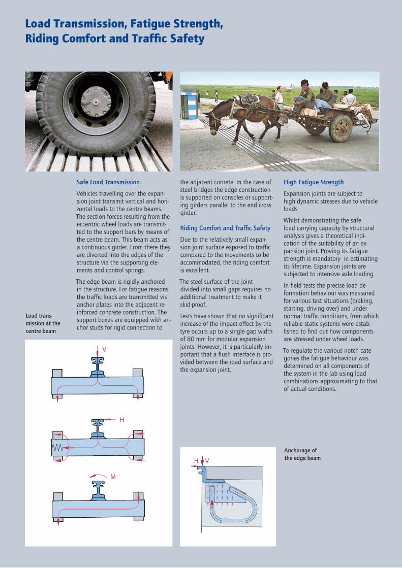
H V
V
M
H
Load Transmission, Fatigue Strength,Riding Comfort and Traffic Safety
the adjacent conrete. In the case of steel bridges the edge construction is supported on consoles or support-ing girders parallel to the end cross girder.
Riding Comfort and Traffic Safety
Due to the relatively small expan- sion joint surface exposed to traffic compared to the movements to be accommodated, the riding comfortis excellent.
The steel surface of the joint divided into small gaps requires no addi tional treatment to make it skid-proof.
Tests have shown that no significant increase of the impact effect by the tyre occurs up to a single gap width of 80 mm for modular expansion joints. However, it is particularly im-portant that a flush interface is pro-vided between the road surface and the expansion joint.
Anchorage of the edge beam
Safe Load Transmission
Vehicles travelling over the expan-sion joint transmit vertical and hori-zontal loads to the centre beams. The section forces resulting from the eccentric wheel loads are transmit-ted to the support bars by means of the centre beam. This beam acts as a continuous girder. From there they are diverted into the edges of the structure via the supporting ele-ments and control springs.
The edge beam is rigidly anchored in the structure. For fatigue reasons the traffic loads are transmitted via anchor plates into the adjacent re- inforced concrete construction. The support boxes are equipped with an-chor studs for rigid connection to
Load trans- mission at the centre beam
High Fatigue Strength
Expansion joints are subject to high dynamic stresses due to vehicle loads.
Whilst demonstrating the safe load carrying capacity by structural analysis gives a theoretical indi- ca tion of the suitability of an ex- pansion joint. Proving its fatigue strength is mandatory in estimating its lifetime. Expansion joints are subjected to intensive axle loading.
In field tests the precise load de- formation behaviour was measured for various test situations (braking, starting, driving over) and under normal traffic conditions, from which reliable static systems were estab-lished to find out how components are stressed under wheel loads.
To regulate the various notch cate-gories the fatigue behaviour was determined on all components of the system in the lab using load combinations approximating to that of actual conditions.

Versatility
Designing an expansion joint is governed by the magnitude and direction of the main movement of the structure in the plane of the carriageway, this being determined in a girder grid joint by the number of expansion gaps and the arrange-ment of the support bars running parallel to this direction, whereas the edge and centre beams are located parallel to the edges of the structure.
In addition to the normal antici pated movements in the plane of the car-riageway, a multitude of secondary movements can occur.
E. g. rotations ϕz due to irregular in-creases in temperature, movements uy due to abutment settings and the resilience of neoprene bearings, movements uz resulting from cantile-ver bridge ends. Also to be taken into account are movements uz resulting from jacking up the superstructure, for instance, when replacing bridge bearings and from the difference be-tween the longitudinal inclination of the carriageway and the horizontal arrangement of the bearings.
The MAURER Girder Grid Joint is capable of handling all such move-ments safely.
Designing and dimensioning ex pansion joints in Germany is dic-tated by the TL/TP-FÜ (Technical De-livery Instructions and Test Spec-ifications) of the Federal Ministry of Transport. MAURER Girder Grid Joints are approved accordingly and are subjected to independent period-ical inspection.
To determine movements accord to German Standard DIN 1072 consideration has to be given to a combination of the following factors:
thermal effects prestress shrinkage and creep superstructure deformations substructure deformations
The following extreme temperature ranges govern the design of expan-sion joints in addition to normal bridge design consideration:
1. For steel and steel/ concrete bridges +75°C/–50°C
2. For concrete bridges and bridges with rolled beams concreted in place +50°C/–40°C
The expansion joint design can be finalised on the basis of site tem-perature measurements prior to instal-lation and following final connection of the structure with the fixed bear-ings. The extreme temperature values can then be reduced by
±15°C for bridges according to (1)and±10°C for bridges according to (2)
The functional range of the strip seals is 0 thru 80 mm perpendicular to the joint (ux) and – 40 mm thru +40 mm parallel to the joint (uy).
All MAURER expansion joints are designed to take movements of 80 mm per joint gap and thus the type designation results as a multiple of 80. According to the requirements of ZTV-K (Additional Technical Con-tract Provisions for Engineering Structures) a movement range of 5 to 70 mm, thus 65 mm, is allowed in Germany. This limiting value applies measured perpendicular to the joint axis.
fixed point
*) *)
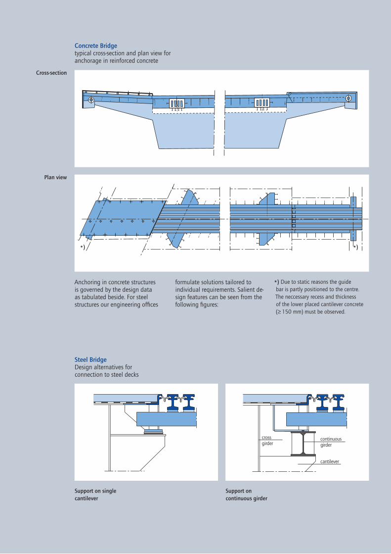
Cross-section
Plan view
*) Due to static reasons the guide bar is partly positioned to the centre. The neccessary recess and thickness of the lower placed cantilever concrete (≥ 150 mm) must be observed.
Support on continuous girder
Steel BridgeDesign alternatives for connection to steel decks
Concrete Bridgetypical cross-section and plan view for anchorage in reinforced concrete
Support on single cantilever
Anchoring in concrete structures is governed by the design data as tabulated beside. For steel structures our engineering offices
formulate solutions tailored to individual requirements. Salient de-sign features can be seen from the following figures:
crossgirder
continuousgirder
cantilever

75c
70
e25 40
ab
h
tF f tF
lF
70
a
150 va
r.15
0
t1,Gt1,G flG
150
70
flG
t1,Gt1,G
150
var.
f t2,Gt2,G
d
150
var.
Cross-section thru carriageway
at support box
Cross-section thru footway with
strip seal 80 G without footway
cover plate
Cross-section thru footway
guide unit (alternative 1)
Cross-section thru carriageway between support boxes
Cross-section thru footway (alternative 2)
Cross-section thru footway with cover plate
Cross-section thru footway guide unit (alternative 2)
Cross-section thru footway
(alternative 1)

y
x
y
x
u
uq
u
uy ux
uz
Design and Product Data
To assist dimensioning, the salient design data is listed in the table, whereby departures are possible within certain limits where space availability is restricted. All dimen-sions are nominal and will be deter-mined according to project. These dimensions are measured at a right angle to the axis of the joint and for angles α of 45° to 90° between this axis and the direction of move- ment. Dimensions for smaller angles or larger movements are available on request.
The form of reinforcement shown is merely a proposal. For reinforce-ment in the area of the carriage-way and footways we recommend a hoop-shaped reinforcement of weld-able 16 mm dia. rebar on a centre-spacing of 200 mm in conjunction with longitudinal rein for cement of the joint and a mesh reinforcement of the gap beneath the joist boxes.
The total movement “u“ in the main direction of movement can be resolved into the two components ux and uy perpendicular and parallel to the direction of the joint respectively. Selecting the size of joint is gov-erned by the component ux and the maximum permissible gap width.
n… number of sealing elementsu... moving direction at superstructureux... movement rectangular to the joint axisuy... movement in joint direction (≤ ± n * 40 mm)uz... vertical adjustment of the edge beams in direction zuq...crosswise movement rectangular to uα... angle between joint axis y and moving direction
- all dimensions are rectangular to the joint axis y- a, f and l apply to an adjustment dimension e = 30 mm for every joint gap and must be adjusted by n x ∆e in case of deviating dimension- recesses for footway joists and pipe passages must be considered individually - smaller gap dimensions by specific structural design- the gap recess t can be reduced by installing the joint at one edge asymmetrically to the joint
MAURER expansion admissible concrete concrete joint movement design data recess dimensions gap dimensions
n type α[°] ux uq uz a b c d h tF t1,G t2,G fmin fmax lF lG
2 D160 90°–45° 160 ±10 ±20 150 217 216 255 340 350 335 335 150 200 850 820
3 D240 90°–60° 240 ±15 ±30 270 297 226 255 350 430 355 355 240 320 1100 950 59°–45° 246 370 4 D320 90°–60° 320 ±20 ±40 390 377 246 275 370 520 365 365 350 440 1390 1080 59°–45° 266 390 5 D400 90°–60° 400 ±20 ±50 510 509 266 275 390 650 375 375 460 560 1760 1210 59°–45° 525 286 410 680 1820 6 D480 90°–60° 480 ±20 ±60 630 588 286 285 410 745 385 400 570 680 2060 1340 59°–45° 606 306 430 760 2090 7 D560 90°–50° 560 ±20 ±70 750 682 306 285 430 800 395 450 680 800 2280 1470 49°-45° 687 326 450 850 2380 8 D640 90°–60° 640 ±20 ±80 870 749 306 285 430 890 405 500 790 920 2570 1600 59°–45° 767 326 450 940 2670
preliminary gap dimension e = 30 mm (all dimensions in mm)
type weight (kg/m) D 160 200 D 240 290 D 320 400 D 400 530 D 480 680 D 560 830 D 640 1040

Resilient Control,Resilient and Prestressed Support
Resilient Control
MAURER Girder Grid Joints adapt continually to deformations in the structure. The control springs provided between the support bars ensure a uniform distribution of the total movement to the individual joint gaps. Steel stops are provided at the support bars to prevent an opening of the individual gap of more than 80 mm.
The springs comprise mainly of closed-cell polyurethane, a material which has a proven record of success for spring elements exposed to dy-namic and impact stresses. The high permissible deformation (up to 80% compression deformation relative to the original free length) permits the production of elements with high permissible spring deflection for a compact design. The natural damp-ing effect of the material affords vibration and impact damping of dynamically stressed components.The special arrangement of the stops
for securing the control springs to the support bars has the effect that the wider the opening of the joint the more the springs are compressed. The springs are compressed in any opening condi-tion of the joint, the precompres-sion being at a mini-mum when the joint is closed. Ad-vantages of this control system are as follows:
adaptability to production tolerances
high reliability durability insensitive to movement
constraints noise damping single gap increase possible
during repair
The reaction forces resulting from the elastic deformations of the strip seals and the control springs are in-dependent of how many of these parts are involved because they func-tion as a series arrangement of springs.
Resilient and Prestressed Support
The support bars of the MAURER Girder Grid Joint are supported by resilient bearing elements i.e. precompressed spring and sliding bearings, located above and below the support bars respectively in the support boxes. This arrange-ment provides a resilient and sliding support in the direction of the structure movement. Precompres-sion of the sliding springs prevents the supports from lifting off the bear-ings and also compensates for man-ufacturing tolerances. The support resilience also serves to eliminate edge pressure in the sliding surfaces.
To compensate for unavoidable differences in height between the edges of the structure, the sliding bearings have been designed to accomodate the resultant inclination of the support bars and to reduce the torsional stiffness.
The Control Principle
Opened joint, cross-section
Opened joint, plan view
Closed joint, cross-section
Closed joint, plan view
Control of MAURER Girder Grid Joints
control spring
control spring
stop

Watertight Connection, Installation,High Functional Reliability and Low Noise Emission
Watertight Connection
To protect the adjacent structural parts from the penetration of dirt and aggressive surface water MAURER Girder Grid Joints feature watertight strip seals to close the gap between the individual steel beams watertight. The MAURER strip seal has become most popular in modular seals sys-tems.
The strip seal is made of EPDM rubber with a bulbous-shaped edge. This is installed in a claw in the edge beam and centre beams without the need for additional clamping bars. The connection is watertight and secure, with the peeling element set below the road surface level. It is protected against direct wheel or snowplough contact.
With its preformed articulated section it is possible to move the strip seal in direction x without any appreciable build-up in reaction forces. Movement in direction z causes deformation of the sealing element.
Sealing elements can be replaced even when the individual gaps are ≥25 mm. The gap width can be enlarged by moving the centre beams. This operation is carried out using special hydraulic equipment. The bulbous edge section of the seal-ing element locks it in the steel claw and is capable of withstanding wheel pressure on any impurities (e.g. stones, grit, snow etc.).
The sealing element adapts to different kinds of joint design and bridge cross sections.
For the protection of the structural concrete and the substructures the interface of the edge beams to the waterproofing layer(s) of the bridge must also be watertight. For this pur-pose the edge beams of MAURER Girder Grid Joints feature an 80 mm wide horizontal steel flange.
Installation
Installation is usually realized by our special fitters and according to the valid work instructions.
High Functional Reliability
Within their anticipated lifetime no malfunction of MAURER expansion joints is expected, but despite this, all synthetic components can be re-placed with minimum effort. Touch-ing up the corrosion protection sys-tem is required during maintenance as is normal for steel structures.
Low Noise Emission
Carriageway expansion joints also add to this noise, the causes of which have been investigated in ex-tensive research by Maurer Söhne to enable MAURER Girder Grid Joints to be optimized in this respect.
Insertion of strip seal into the edge beam
40 mm gap width, mid position
Deformation features of the
strip seal
80 mm gap width, max. position
150 mm gap width, over-expanded position
Residents in the vicinity of such expansion joints find the sudden change in the noise pattern particu-larly disturbing, the criteria for which is not so much the noise level as measured but the magnitude of the fleeting change in frequency and the pulsed element of the noise pattern, whereby a basic distinction is made between noise emitted upwards from the carriageway and the noise projected downwards through the gap between the two structural components.
All supporting elements of MAURER Girder Grid Joints which are exposed to traffic loads are supported by high-quality resilient synthetics which distinguish such designs from those having rigid support. The structural gap can be dammed downwards. Maurer Söhne offers tailored solutions for each and every application.
Noise control to the top is effected by optimizing the road surfacing connection and supporting the wheel when crossing the joint. Angular joint design, finger-type bridging and joint sealing afford relief.

Detail Features
Watertight design of
parapet
Horizontal bend and kerb units
Connection of a modular joint to
a single seal joint
Intersection with rail of tram
Special kerb unit

413G
B·20
00·1
2.13
Storebælt East Bridge, Denmark
TGV Viaduct,Avignon
Vasco da Gama Bridge, Portugal
Bridge over the River Main,
Nantenbach
Yang Pu Bridge, China Oberbaum Bridge, Berlin
Maurer Söhne head officeFrankfurter Ring 193, D-80807 Munich/GermanyP.O. Box 44 01 45, 80750 Munich/Germanyphone: +49 89 32394–0fax: +49 89 32394–[email protected]
Maurer Söhne branch officeZum Holzplatz 2, 44536 Lünen/GermanyP.O. Box 63 40, 44520 Lünen/Germanyphone: +49 231 43401–0fax: +49 231 43401–[email protected]
Maurer Söhne subsidiaryKamenzer Str. 52, 02884 Bernsdorf/GermanyP.O. Box 55, 02994 Bernsdorf/Germanyphone: +49 35723 237–0fax: +49 35723 237–[email protected]