MATLAB/Simulink User's Manual - Siemens · SIEMENS Teamcenter 10.1 Systems Engineering and...
30
SIEMENS SIEMENS SIEMENS Teamcenter 10.1 Systems Engineering and Requirements Management MATLAB/Simulink Interface User's Manual REQ00007 • L
Transcript of MATLAB/Simulink User's Manual - Siemens · SIEMENS Teamcenter 10.1 Systems Engineering and...

SIEMENSSIEMENSSIEMENS
Teamcenter 10.1Systems Engineeringand RequirementsManagement
MATLAB/SimulinkInterfaceUser's Manual
REQ00007 • L

Manual History
ManualRevision
Teamcenter Systems Engineering andRequirements ManagementVersion
PublicationDate
A 2005 SR1 October 2006B 2007 December 2006C 2007.1 April 2007D 2007.2 September 2007E 2007.3 January 2008F 8 January 2009G 8.1 October 2009H 8.2 October 2010I 9 July 2011J 9.1 May 2012J1 9.1.5 January 2014K 10.0 January 2015L 10.1 September 2016
This edition obsoletes all previous editions.
2 MatLAB Interface REQ00007 L

Contents
Manual History . . . . . . . . . . . . . . . . . . . . . . . . . . . . . . . . . . . . . . . . . . . . . . . . . . . . . . . . 2
Preface . . . . . . . . . . . . . . . . . . . . . . . . . . . . . . . . . . . . . . . . . . . . . . . . . . . . . . . . . . . . . 5
Audience . . . . . . . . . . . . . . . . . . . . . . . . . . . . . . . . . . . . . . . . . . . . . . . . . . . . . . . . . . . . 5Organization . . . . . . . . . . . . . . . . . . . . . . . . . . . . . . . . . . . . . . . . . . . . . . . . . . . . . . . . . . 5Browser and Dialog Window Examples . . . . . . . . . . . . . . . . . . . . . . . . . . . . . . . . . . . . . . . . 6Names and Values . . . . . . . . . . . . . . . . . . . . . . . . . . . . . . . . . . . . . . . . . . . . . . . . . . . . . . 6Submitting Comments . . . . . . . . . . . . . . . . . . . . . . . . . . . . . . . . . . . . . . . . . . . . . . . . . . . . 7Proprietary and Restricted Rights Notice . . . . . . . . . . . . . . . . . . . . . . . . . . . . . . . . . . . . . . . 7
Overview of the Simulink Interface . . . . . . . . . . . . . . . . . . . . . . . . . . . . . . . . . . . . . . . . 1-1
Model Objects in Architect/Requirements . . . . . . . . . . . . . . . . . . . . . . . . . . . . . . . . . . . . . . 1-1Traceability for Model Blocks . . . . . . . . . . . . . . . . . . . . . . . . . . . . . . . . . . . . . . . . . . . . . . 1-1
Working With Models . . . . . . . . . . . . . . . . . . . . . . . . . . . . . . . . . . . . . . . . . . . . . . . . . . 2-1
Creating a New Model Object . . . . . . . . . . . . . . . . . . . . . . . . . . . . . . . . . . . . . . . . . . . . . . 2-1Attaching an Existing Simulink Model to a Building Block . . . . . . . . . . . . . . . . . . . . . . . . . . . 2-2Editing a Model . . . . . . . . . . . . . . . . . . . . . . . . . . . . . . . . . . . . . . . . . . . . . . . . . . . . . . . 2-3Viewing a Model . . . . . . . . . . . . . . . . . . . . . . . . . . . . . . . . . . . . . . . . . . . . . . . . . . . . . . . 2-5Unsupported Functionalities . . . . . . . . . . . . . . . . . . . . . . . . . . . . . . . . . . . . . . . . . . . . . . . 2-6
Linking Model Blocks to Requirements . . . . . . . . . . . . . . . . . . . . . . . . . . . . . . . . . . . . . 3-1
Creating a Trace Link to a Model Block . . . . . . . . . . . . . . . . . . . . . . . . . . . . . . . . . . . . . . . 3-1Navigating to Linked Objects in Architect/Requirements . . . . . . . . . . . . . . . . . . . . . . . . . . . . 3-3Viewing Linked Requirement Content . . . . . . . . . . . . . . . . . . . . . . . . . . . . . . . . . . . . . . . . 3-4Deleting a Trace Link . . . . . . . . . . . . . . . . . . . . . . . . . . . . . . . . . . . . . . . . . . . . . . . . . . . 3-4
Index . . . . . . . . . . . . . . . . . . . . . . . . . . . . . . . . . . . . . . . . . . . . . . . . . . . . . . . . . . . Index-1
REQ00007 L MatLAB Interface 3

Preface
This manual is a users reference for the Systems Architect/Requirements Management interface withMATLAB/Simulink. Architect/Requirements belongs to the Siemens PLM Software portfolio of digitalproduct lifecycle management software and services.
AudienceThis manual is for project team members who use Architect/Requirements and MATLAB/Simulink toillustrate system elements with building blocks and to model their behavior. This manual providesboth conceptual information and step-by-step instructions for specific tasks.
This manual assumes that you are familiar with your project and your product development process,that you understand general computer terminology and the Microsoft Windows operating system, andthat you have experience with MATLAB/Simulink.
• An Architect/Requirements Architect license is required for the procedures in thismanual. If you have questions about your license, consult your Architect/Requirementsproject administrator.
• Simulink’s Verification and Validation Toolbox is required for linking model blocks torequirements. However, you can create and attach models without this software.
OrganizationThis manual contains the following chapters:
Chapter 1 Overview of the Simulink Interface presents an overview of Architect/Requirementsand MatLAB/Simulink, discussing the basic concepts of its purpose andapplication.
Chapter 2 Working With Models contains instructions for creating new model objects,attaching existing Simulink models to building blocks, and editing and viewinga model.
Chapter 3 Linking Model Blocks to Requirements contains instructions for creating tracelinks to model blocks, navigating to linked objects in Architect/Requirements,viewing linked requirement content, and deleting trace links.
REQ00007 L MatLAB Interface 5

Preface
Browser and Dialog Window ExamplesThe examples of browsers and dialog windows in this manual may appear different from those yousee on your screen:
• The examples reflect Systems Architect/Requirements Management as initially installed at yoursite. Your enterprise may customize the browsers and dialog windows such that they appeardifferent from those in the examples.
• The examples reflect individual Systems Architect/Requirements Management modules. If youinstall additional modules, your dialog windows and browsers reflect the additional modules.
• The examples reflect Systems Architect/Requirements Management installed on a Windowsplatform.
Names and ValuesThis manual represents system names, file names, and values in fonts that help you interpret thename or value. For example:
Change or add the parameter to the initsid.ora file.
The conventions are:
Bold Bold font represents unvarying text or numbers within a name or value.Capitalization is as it appears.
Italic Italic font represents text or numbers that vary within a name or value. Thecharacters in italic text describe the entry. Letters are shown in lowercase, butthe varying text may include uppercase letters.
In initsid.ora, sid identifies a varying portion of the name (a unique system ID).For example, the name of the file might be:
initBlue5.oratext-text A hyphen separates two words that describe a single entry.
6 MatLAB Interface REQ00007 L
Preface

Preface
Submitting CommentsPortions of Teamcenter software are provided by third-party vendors. Special agreements with thesevendors require Siemens PLM Software to handle all problem reports concerning the software theyprovide. Please submit all comments directly to Siemens PLM Software.
Please feel free to share with us your opinion on the usability of this manual, to suggest specificimprovements, and to report errors. Mail your comments to:
Siemens PLM Software Technical Communications5939 Rice Creek ParkwayShoreview, MN 55126U.S.A.
To submit an incident report, you can use the Siemens PLM Software GTAC online support toolsat the following URL:
http://www.plm.automation.siemens.com/en_us/support/gtac/
Proprietary and Restricted Rights NoticeThis software and related documentation are proprietary to Siemens Product Lifecycle ManagementSoftware Inc.
© 2016 Siemens Product Lifecycle Management Software Inc. All Rights Reserved.
All trademarks belong to their respective holders.
REQ00007 L MatLAB Interface 7
Preface

Chapter 1: Overview of the Simulink Interface
Model Objects in Architect/Requirements . . . . . . . . . . . . . . . . . . . . . . . . . . . . . . . . . . . . . . 1-1
Traceability for Model Blocks . . . . . . . . . . . . . . . . . . . . . . . . . . . . . . . . . . . . . . . . . . . . . . 1-1
REQ00007 L MatLAB Interface


Chapter 1: Overview of the Simulink Interface
This chapter presents an overview of the Architect/Requirements interface with Simulink, discussingthe basic concepts of its purpose and application.
The Architect/Requirements interface with Simulink brings together requirements managementfeatures and Simulink's mathematical visualization and evaluation capabilities. The interface allowsyou to simulate the behavior of Architect/Requirements building blocks in Simulink models. Whenmodels are stored as model objects in the Architect/Requirements database, individual model blockscan be linked to defining requirements for traceability.
You must have an Architect/Requirements Architect license to use the Simulink interface.If you have questions about your license, consult your Architect/Requirements projectadministrator.
For more information about constructing system views with building blocks, see the SystemsArchitect/Requirements Management User's Manual.
Model Objects in Architect/RequirementsEach model object in the Architect/Requirements database is owned by a parent building block.There are two ways to store a model object:
• Create a new model object in Architect/Requirements.
You then construct the block diagram in the Simulink Model Editor.
• Attach an existing Simulink model to a selected building block.
You can edit the block diagram in the Simulink Model Editor.
A building block is created in the database for each block that you add to a model. For moreinformation, see chapter 2, Working With Models.
Traceability for Model BlocksTo trace a model block upstream to its defining conditions, you can create a trace link from arequirement in Architect/Requirements to the model block in the Simulink Model Editor. The modelmust exist as an object in the Architect/Requirements database.
REQ00007 L MatLAB Interface 1-1

Chapter 1: Overview of the Simulink Interface
Simulink’s Verification and Validation Toolbox is required for linking model blocks torequirements. However, you can create and attach models without this software.
For more information, see chapter 3, Linking Model Blocks to Requirements.
1-2 MatLAB Interface REQ00007 L
Chapter 1: Overview of the Simulink Interface
Chapter 2: Working With Models
Creating a New Model Object . . . . . . . . . . . . . . . . . . . . . . . . . . . . . . . . . . . . . . . . . . . . . . 2-1
Attaching an Existing Simulink Model to a Building Block . . . . . . . . . . . . . . . . . . . . . . . . . . . 2-2
Editing a Model . . . . . . . . . . . . . . . . . . . . . . . . . . . . . . . . . . . . . . . . . . . . . . . . . . . . . . . 2-3
Viewing a Model . . . . . . . . . . . . . . . . . . . . . . . . . . . . . . . . . . . . . . . . . . . . . . . . . . . . . . . 2-5
Unsupported Functionalities . . . . . . . . . . . . . . . . . . . . . . . . . . . . . . . . . . . . . . . . . . . . . . . 2-6
REQ00007 L MatLAB Interface


Chapter 2: Working With Models
This chapter contains instructions for creating new model objects, attaching existing Simulink modelsto building blocks, and editing and viewing a model.
Models help to visualize concepts or components of a system. A model illustrates a systemdecomposition by building blocks and connections that represent system elements and their behavior.
Creating a New Model ObjectCreate a new model object in Architect/Requirements before constructing the block diagram throughthe MATLAB/Simulink interface. You can create any number of model objects for a given buildingblock.
You must have an Architect license to create a model. If you have questions about yourlicense, consult your Architect/Requirements project administrator.
1. Select the owning building block for the model, and then pull down the File menu and choosethe Matlab→Create Model options.
The Attachments tab displays the new model with a default name in an open text field.
2. Enter a meaningful name, and then press the enter key.
Architect/Requirements launches MATLAB, which displays the Simulink Library Browser and anempty Simulink Model Editor window.
You can leave the model open to add blocks and lines from the Library Browser. Or, you canclose the model and construct the block diagram later. For more information, see Editing aModel, later in this chapter.
Procedure Notes
Step 1: You can also right-click the building block and choose the Matlab→Create Model optionsfrom the popup menu.
REQ00007 L MatLAB Interface 2-1

Chapter 2: Working With Models
Attaching an Existing Simulink Model to a Building BlockSimulink models that are stored outside the Architect/Requirements database can be attachedto building blocks in Architect/Requirements. For example, you may have models on your localdesktop or on a shared drive. You can reuse these existing models to save time in working withcomplex systems.
• You must have an Architect license to attach a model.
If you have questions about your license, consult your Architect/Requirements projectadministrator.
• Blocks and lines in the model do not automatically create building blocks andconnections in Architect/Requirements.
After attaching the model, you can edit the model to add building blocks and connectionsto the database. For more information, see Editing a Model, later in this chapter.
1. Select the owning building block for the model, and then pull down the File menu and choosethe Matlab→Attach MATLAB Model options.
Architect/Requirements displays the Open dialog window, which lists existing folders and files inthe current drive or folder.
2. Select the model in the list, or enter the model name in the File name field.
If the model to attach is not in the list, you can use the Look in field to change the drive or folder.
3. Click Open, or press the enter key.
A progress indicator and an information message show that the attachment is in progress. Whenthe process is complete, a confirmation message is displayed.
The model is attached to the selected building block and is added to the Attachments tab.
Procedure Notes
Step 1: You can also right-click the building block and choose the Matlab→Attach MATLAB Modeloptions from the popup menu.
2-2 MatLAB Interface REQ00007 L
Chapter 2: Working With Models
Working With Models
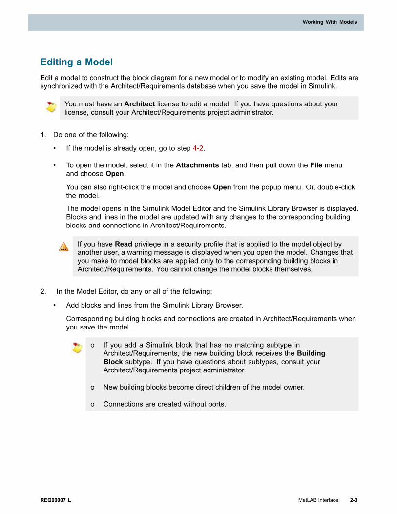
Editing a ModelEdit a model to construct the block diagram for a new model or to modify an existing model. Edits aresynchronized with the Architect/Requirements database when you save the model in Simulink.
You must have an Architect license to edit a model. If you have questions about yourlicense, consult your Architect/Requirements project administrator.
1. Do one of the following:
• If the model is already open, go to step 4-2.
• To open the model, select it in the Attachments tab, and then pull down the File menuand choose Open.
You can also right-click the model and choose Open from the popup menu. Or, double-clickthe model.
The model opens in the Simulink Model Editor and the Simulink Library Browser is displayed.Blocks and lines in the model are updated with any changes to the corresponding buildingblocks and connections in Architect/Requirements.
If you have Read privilege in a security profile that is applied to the model object byanother user, a warning message is displayed when you open the model. Changes thatyou make to model blocks are applied only to the corresponding building blocks inArchitect/Requirements. You cannot change the model blocks themselves.
2. In the Model Editor, do any or all of the following:
• Add blocks and lines from the Simulink Library Browser.
Corresponding building blocks and connections are created in Architect/Requirements whenyou save the model.
o If you add a Simulink block that has no matching subtype inArchitect/Requirements, the new building block receives the BuildingBlock subtype. If you have questions about subtypes, consult yourArchitect/Requirements project administrator.
o New building blocks become direct children of the model owner.
o Connections are created without ports.
REQ00007 L MatLAB Interface 2-3
Working With Models

Chapter 2: Working With Models
You can also add existing building blocks from Architect/Requirements:
a. Select a building block, and then pull down the File menu and choose theMatlab→Copy To Matlab options.
You can also right-click the building block and choose the Matlab→Copy ToMatlab options from the popup menu.
b. In the Model Editor, add a new block from the Library Browser.
c. Right-click the new block in the model and choose the Teamcenter→AssociateTo Block options from the popup menu.
When you save the model, the new model block receives the exact propertiesof the Architect/Requirements building block. Also, any updates to the modelblock are applied to the building block.
• Change existing blocks and lines, using Simulink functions.
Changes are applied in Architect/Requirements when you save the model.
• Copy a block within the model and create a corresponding building block inArchitect/Requirements:
o Select the block, and then right-click the canvas in the Model Editor and choose Pasteand Create from the popup menu.
The copy appears with a unique name in the upper left corner of the canvas.
The building block is created in Architect/Requirements when you save the model.
To create a new item in Simulink, you must avoid using the mouse to drop theelement on the canvas in the Model Editor. Such an item does not carry a uniqueidentifier that allows it to be associated with an Architect/Requirements buildingblock.
To use an existing block within a model to create a new instance:
a. Right-click the selected block in the model and choose Copy.
b. Right-click the canvas in the Model Editor and choose Paste and Create fromthe popup menu.
The copied block is pasted as a new block in the model. Its name, which youcan edit, is a combination of the original name and an automatically-generatednumber. The Tag property value of this block is empty.
When you save this newly created block, it is created as a building block inArchitect/Requirements.
• Delete existing blocks and lines, using Simulink functions.
The corresponding building blocks and connections remain in Architect/Requirements.
2-4 MatLAB Interface REQ00007 L
Chapter 2: Working With Models

Working With Models
• Delete building blocks and connections from Architect/Requirements while keeping blocksand lines in the model:
o Right-click the block or line in the model and choose the Teamcenter→Delete in TcSEoptions from the popup menu.
The corresponding building block or connection is deleted from Architect/Requirementswhen you save the model.
For information about using the Simulink Model Editor and Library Browser, see theSimulink Help.
3. To apply the edits in Architect/Requirements, save the model in the Model Editor.
You can also save the model in a location outside the database, for example, on yourlocal desktop. However, trace links cannot be created between that model and objectsin Architect/Requirements.
The MATLAB interface with Architect/Requirements uses the Tag property of the MATLABmodel block to uniquely identify the blocks in Architect/Requirements. When blocks fromthe Simulink library are added in the model, they have a preset Tag property value. In thisscenario, on saving the model, the MATLAB interface modifies the Tag property value withthe data as per the Architect/Requirements format.
Hence, you must be careful about the usage of the Tag property with the MATLAB interface.
Viewing a ModelFrom the Attachments tab, you can open a model for viewing in read-only mode. To open a modelfor editing, see Editing a Model, earlier in this chapter.
You must have an Architect license to view a model. If you have questions about yourlicense, consult your Architect/Requirements project administrator.
• Select the model, and then pull down the File menu and choose Open Read-Only. Or, right-clickthe model and choose Open Read-Only from the popup menu.
The read-only model opens in the Simulink Model Editor.
Objects in the model are updated with any changes to the corresponding objects inArchitect/Requirements.
REQ00007 L MatLAB Interface 2-5
Working With Models

Chapter 2: Working With Models
Unsupported FunctionalitiesThe following functionalities are not supported by the MATLAB interface with Architect/Requirements:
• MATLAB's subsystem
Blocks in the subsystems can be created and associated with a Architect/Requirements buildingblock. However, the subsequent actions on those objects may fail to synchronize correctlywith Architect/Requirements.
For example, errors similar to Error using ==> get_param Invalid Simulink object name:Subsystem are encountered when you try to delete a trace link between a requirement and ablock inside a subsystem from MATLAB/Simulink.
• MATLAB's branched connections between blocks
A model that has MATLAB's branched connections between blocks is not allowed to be saved inArchitect/Requirements by the MATLAB interface.
For example, the error message Model has Branch connection and Teamcenter does notsupport branch connection. Change the model accordingly and try saving it is encountered.
2-6 MatLAB Interface REQ00007 L
Chapter 2: Working With Models

Chapter 3: Linking Model Blocks to Requirements
Creating a Trace Link to a Model Block . . . . . . . . . . . . . . . . . . . . . . . . . . . . . . . . . . . . . . . 3-1
Navigating to Linked Objects in Architect/Requirements . . . . . . . . . . . . . . . . . . . . . . . . . . . . 3-3
Viewing Linked Requirement Content . . . . . . . . . . . . . . . . . . . . . . . . . . . . . . . . . . . . . . . . 3-4
Deleting a Trace Link . . . . . . . . . . . . . . . . . . . . . . . . . . . . . . . . . . . . . . . . . . . . . . . . . . . 3-4
REQ00007 L MatLAB Interface


Chapter 3: Linking Model Blocks to Requirements
This chapter contains instructions for creating trace links to model blocks, navigating to linked objectsin Architect/Requirements, viewing linked requirement content, and deleting trace links.
• An Architect/Requirements Architect license is required for all procedures in thischapter. If you have questions about your license, consult your Architect/Requirementsproject administrator.
• The Simulink Verification and Validation Toolbox must be installed on your computer.
Creating a Trace Link to a Model BlockBy creating a trace link from a defining requirement in Architect/Requirements to a block in a Simulinkmodel, you can trace the model block upstream to the conditions that define its design constraints. Amodel block can have trace links from multiple defining requirements.
The model must exist as an object in Architect/Requirements. You cannot link to blocks inmodels that reside outside the database, for example, on your local desktop.
1. Select the requirement, and then pull down the File menu and choose the Matlab→Copy ToMatlab options.
The requirement LOID is placed in the Clipboard.
2. With the model open in the Simulink Model Editor, right-click the target block and choose theTeamcenter→Paste from Teamcenter options from the popup menu.
3. Save the model in the Model Editor.
In the Architect/Requirements Links tab, the trace link is created in the Relations subtab. In theTrace subtab, the building block associated with the model block is added in the ComplyingTrace column.
REQ00007 L MatLAB Interface 3-1

Chapter 3: Linking Model Blocks to Requirements
When you right-click the model block and choose Requirements from the popupmenu, a submenu lists each defining requirement for the block. Each time the modelis opened, the model block's list is synchronized with the current trace link set for thecorresponding building block.
Linked requirements are added to and removed from the list according to changes inArchitect/Requirements since the model was last opened:
• If trace links were added to the building block, those requirements are addedto the list.
• If trace links were deleted from the building block, those requirements are removedfrom the list.
• If the corresponding building block was copied to a different Architect/Requirementsproject:
o A linked requirement remains in the list if the requirement was included in theselection with the copied building block.
o A linked requirement is removed from the list if the requirement was not copiedwith the building block.
Procedure Notes
Step 1: You can also right-click the requirement and choose the Matlab→Copy To Matlab optionsfrom the popup menu.
3-2 MatLAB Interface REQ00007 L
Chapter 3: Linking Model Blocks to Requirements
Linking Model Blocks to Requirements
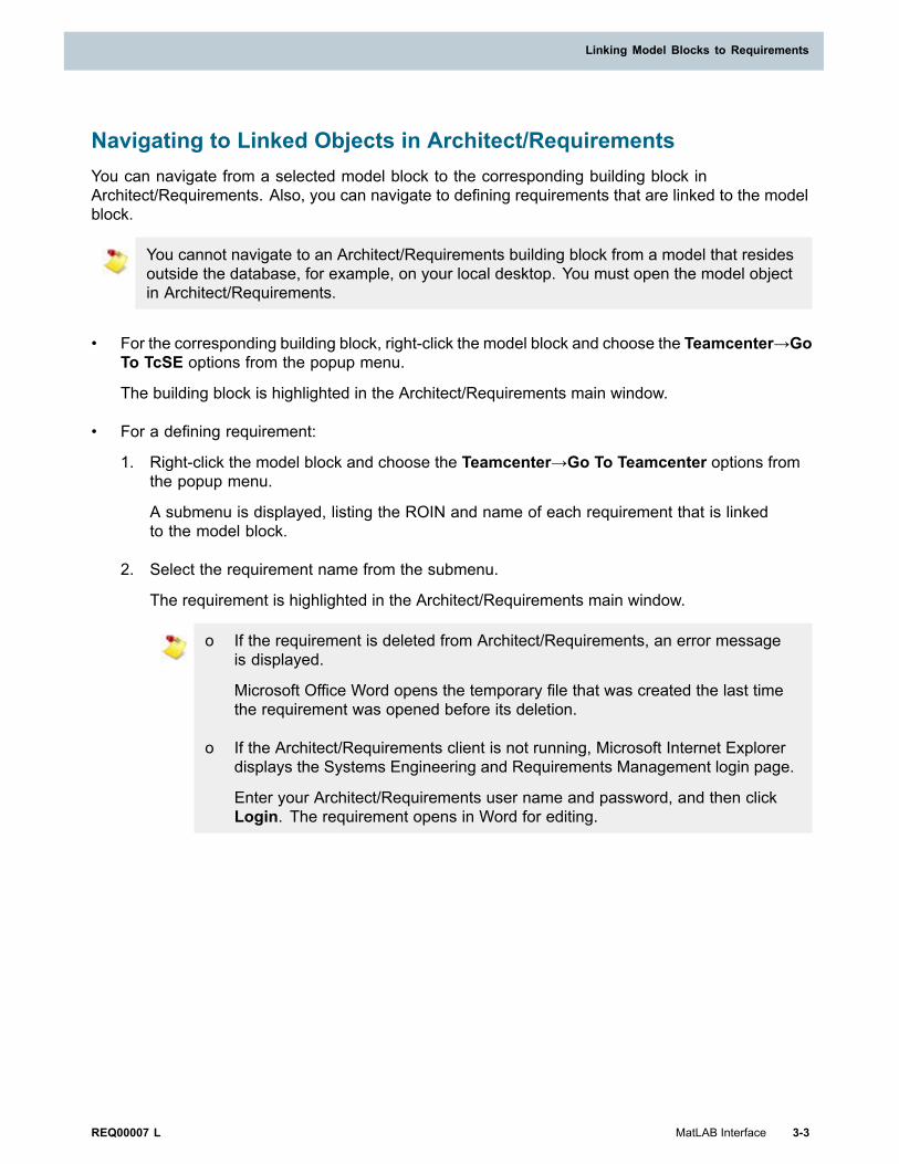
Navigating to Linked Objects in Architect/RequirementsYou can navigate from a selected model block to the corresponding building block inArchitect/Requirements. Also, you can navigate to defining requirements that are linked to the modelblock.
You cannot navigate to an Architect/Requirements building block from a model that residesoutside the database, for example, on your local desktop. You must open the model objectin Architect/Requirements.
• For the corresponding building block, right-click the model block and choose the Teamcenter→GoTo TcSE options from the popup menu.
The building block is highlighted in the Architect/Requirements main window.
• For a defining requirement:
1. Right-click the model block and choose the Teamcenter→Go To Teamcenter options fromthe popup menu.
A submenu is displayed, listing the ROIN and name of each requirement that is linkedto the model block.
2. Select the requirement name from the submenu.
The requirement is highlighted in the Architect/Requirements main window.
o If the requirement is deleted from Architect/Requirements, an error messageis displayed.
Microsoft Office Word opens the temporary file that was created the last timethe requirement was opened before its deletion.
o If the Architect/Requirements client is not running, Microsoft Internet Explorerdisplays the Systems Engineering and Requirements Management login page.
Enter your Architect/Requirements user name and password, and then clickLogin. The requirement opens in Word for editing.
REQ00007 L MatLAB Interface 3-3
Linking Model Blocks to Requirements

Chapter 3: Linking Model Blocks to Requirements
Viewing Linked Requirement ContentTo view the content of a defining requirement for a model block, you can open the requirement inMicrosoft Office Word directly from the model.
1. Right-click the model block and choose Requirements from the popup menu.
A submenu lists the name of each requirement that is linked to the model block.
2. Select the requirement name from the submenu.
The requirement opens in a read-only Word file, which is stored on your computer as a temporaryfile.
The first time you open the requirement, the temporary file contains the latest content fromthe Architect/Requirements database. If you close and reopen the requirement while themodel is open, you reopen the same temporary file.
This file does not reflect content changes that may be made in the database while themodel is open. To generate a new temporary file with the latest database content, close themodel, reopen it, and repeat this procedure.
If the temporary file is deleted from your computer, a new file is generated with the latestcontent from the database.
Deleting a Trace LinkDefining requirements for a model block are listed on a submenu when you right-click the blockand choose Requirements from the popup menu. Each listed requirement has a trace link to theArchitect/Requirements building block that corresponds to the model block.
You can delete a trace link directly from the model block, for example, if the requirement's content ischanged and is no longer valid for the design. Architect/Requirements automatically removes thetrace link from the requirement and building block.
1. Right-click the model block and choose the Requirements→Edit/Add Links options from thepopup menu.
Simulink displays the Requirements dialog window. On the Requirements tab, the list paneshows the name of each linked requirement.
2. Select the name of the requirement that has the trace link, and then click the Delete button.
The requirement name is deleted from the list pane.
3. Click OK to close the dialog window.
The requirement is deleted from the list of linked requirements for the block.
4. Save the model in the Simulink Model Editor.
In Architect/Requirements, the trace link is removed from the Relations subtab of the Links taband is placed in your Recycle Bin.
3-4 MatLAB Interface REQ00007 L
Chapter 3: Linking Model Blocks to Requirements

Index
AAttaching a Simulink Model to an Architect/Requirements Building Block . . . . . . . . 2-2
BBrowser and dialog window examples . . . . 6Building blocksAttaching a model . . . . . . . . . . . . . . . 2-2Creating a model . . . . . . . . . . . . . . . . 2-1Editing a model . . . . . . . . . . . . . . . . . 2-3Viewing a model . . . . . . . . . . . . . . . . 2-5
CConventionsBrowser and dialog window examples . . 6Names . . . . . . . . . . . . . . . . . . . . . . . 6Values . . . . . . . . . . . . . . . . . . . . . . . . 6
CreatingModel . . . . . . . . . . . . . . . . . . . . . . . 2-1
DDialog Window examples . . . . . . . . . . . . 6Dialog windows, Simulink,Requirements . . . . . . . . . . . . . . . . . . 3-4
EEditingModel . . . . . . . . . . . . . . . . . . . . . . . 2-3
LLibrary, Simulink . . . . . . . . . . . . . . . . . . 2-3
MModel Editor, Simulink . . . . . . . . . . . . . . 2-3
ModelsAttaching to building blocks . . . . . . . . 2-2Creating . . . . . . . . . . . . . . . . . . . . . 2-1Editing . . . . . . . . . . . . . . . . . . . . . . . 2-3Viewing in Architect/Requirements . . . . 2-5
N
Name conventions . . . . . . . . . . . . . . . . . 6
O
OptionsViewing a Requirement from MATLAB/
Simulink . . . . . . . . . . . . . . . . . . . 3-1Overview . . . . . . . . . . . . . . . . . . . . . . 1-8
R
Requirements and MATLAB/SimulinkCreating Links . . . . . . . . . . . . . . . . . 3-1
Requirements, Simulink dialog window . . 3-4
S
SimulinkLibrary . . . . . . . . . . . . . . . . . . . . . . . 2-3Model Editor . . . . . . . . . . . . . . . . . . . 2-3
U
Unsupported Functionalities . . . . . . . . . . 2-6
V
Value conventions . . . . . . . . . . . . . . . . . 6Viewing a Model in Architect/Requirements . . . . . . . . . . . . . . . . . . 2-5
REQ00007 L MatLAB Interface Index-1


Siemens Industry Software
HeadquartersGranite Park One5800 Granite ParkwaySuite 600Plano, TX 75024USA+1 972 987 3000
AmericasGranite Park One5800 Granite ParkwaySuite 600Plano, TX 75024USA+1 314 264 8499
EuropeStephenson HouseSir William Siemens SquareFrimley, CamberleySurrey, GU16 8QD+44 (0) 1276 413200
Asia-PacificSuites 4301-4302, 43/FAIA Kowloon Tower, Landmark East100 How Ming StreetKwun Tong, KowloonHong Kong+852 2230 3308
About Siemens PLM Software
Siemens PLM Software, a business unit of the SiemensIndustry Automation Division, is a leading global providerof product lifecycle management (PLM) software andservices with 7 million licensed seats and 71,000 customersworldwide. Headquartered in Plano, Texas, SiemensPLM Software works collaboratively with companiesto deliver open solutions that help them turn moreideas into successful products. For more informationon Siemens PLM Software products and services, visitwww.siemens.com/plm.
© 2016 Siemens Product Lifecycle ManagementSoftware Inc. Siemens and the Siemens logo areregistered trademarks of Siemens AG. D-Cubed,Femap, Geolus, GO PLM, I-deas, Insight, JT, NX,Parasolid, Solid Edge, Teamcenter, Tecnomatix andVelocity Series are trademarks or registered trademarksof Siemens Product Lifecycle Management SoftwareInc. or its subsidiaries in the United States and in othercountries. All other trademarks, registered trademarksor service marks belong to their respective holders.