MATKI ONE CORNER PIVOT 0946AF · WIDTH ANEL C - DOOR OPENING B D ... STAGE 1 a TOP VIEW FIXED PANEL...
16
MATKI ONE MOPC - CORNER PIVOT INSTALLATION PARTS LIST MATKI PLC, CHURCHWARD ROAD, YATE, BRISTOL, BS37 5PL TELEPHONE:01454 328816 (AFTER SALES) FAX:01454 328821 EMAIL: [email protected] 0946AF 07/15 ®
Transcript of MATKI ONE CORNER PIVOT 0946AF · WIDTH ANEL C - DOOR OPENING B D ... STAGE 1 a TOP VIEW FIXED PANEL...

MATKI ONEMOPC - CORNER PIVOT
INSTALLATION
PARTS LIST
MATKI PLC, CHURCHWARD ROAD, YATE, BRISTOL, BS37 5PLTELEPHONE:01454 328816 (AFTER SALES) FAX:01454 328821 EMAIL: [email protected]
0946AF 07/15
®

2000
E - SIDE PANEL
A - OVERALL WIDTH
C - DOOR OPENING
B
D
Before disposing of carton and/or commencing assembly, please check all the parts to ascertain that none are missing and they are all undamaged. No claim for missing/damaged parts will be accepted once the packing carton has been disposed of and/or assembly has commenced.In case of query contact your Stockist with details of model number and details of serial number.
PREPARATION IMPORTANT
1. Please read complete installation instructions before fitting for Enclosure and Tray (if fitting).
2. We recommend the use of Safety glasses and Non slip gloves when handling the glass panels.
3. Ensure that the product can be fixed to a solid masonry wall or suitable timber stud work grade C16/C24 in the area behind the Wall frames.
4. Shower trays or tiled floors must be absolutely level where enclosures are fitted
5. If fitting a tray we recommend a drainage test is carried out before the tray is tiled in position.
6. The assembly should be installed onto a waterproof wall covering and installed after the Tray and wall coverings are in place. Where Tiling lips are provided Trays should be let into the Wall with the Tiling lip flush with the wall to allow the Tiling to overlap the Tiling lip.
7. Seal between tray and tiles. Remove any excess sealant from the area/joint between the tray and the tiles where the Wall Mount is to be fitted. This will ensure the Wall mount fits correctly to the wall and tray/or tiled floor.
CAUTION: TEMPERED GLASS CANNOT BE CUT, POLISHED METAL AND CHROME CAN BE SCRATCHED. CAREFULLY REMOVE ASSEMBLY FROM CARTON, DO NOT PLACE GLASS ON HARD FLOOR OR EXPOSE EDGES TO IMPACT.
IMPORTANTTOOLS REQUIRED
Masonry Drill bit 6mm, Tape Measure, Screw Drivers, Safety Glasses, Electric Drill, Level, Pencil, Adjustable Spanners, Non Slip Gloves
Dimensions are approximate
DIMENSIONS CORNER PIVOT760/800/900 x 760/800/900
LH CORNER RH CORNER
MODEL A B C D MOPC760 732-752 80-100 482 100 MOPC800 772-792 80-100 522 100 MOPC900 872-892 80-100 622 100 SIDE PANEL E MOPCSP760 732-752 MOPCSP800 772-792 MOPCSP900 872-892

STAGE 1
a TOP VIEW FIXED PANEL WALL MOUNT
THRESHOLD
2.5mm
THRESHOLDADJUSTER
x 3
b
Ø6
SILICONx 3
x 3
x 3
THRESHOLD
THIS PAGE SHOWS THE PANEL INSTALLATION FOR A LH CORNER. REVERSE FOR RH.
WALL MOUNT
This stage is describing the fitting of the Fixed panel wall mountBefore fitting the enclosure please check that your product will fit the finished aperture size.(See dimensions)a. Remove and set aside the threshold covers from the horizontal threshold. Place the horizontal threshold into position on tray, ensuring the threshold corner bracket is at the corner side of the enclosure (threshold extrusion is unhanded, rotate by 180° to reverse hand). The threshold extrusion should be positioned as close to the outside edge of the tray as possible, within the max and min side panel measurements (take into account that the front face of the fixed panel wall mount sits 2.5mm in front of the threshold when positioning at the front of the tray). Position the fixed panel wall mount on to the wall over threshold (wall mount has a top and bottom, wall mount cut-out with socket set screw is the top of the wall mount). Ensure the threshold adjuster fits up into the back of the wall mount extrusion in the recess as shown. Adjust position of threshold adjuster as required, to adjust loosen screw 1 full turn, re-tighten after adjustment, do not over tighten. Plumb the wall mount for upright and mark the fixing holes in the centre of the slots.
b. Drill 3 x fixing holes in the wall and insert wall plugs. Clean area and apply silicon sealant to the area behind the wall mount between the tray and tiles and 100mm up the wall, central to the width of the wall mount. Fit the wall mount using the No.8 x 32mm Pan Head Screws.
THRESHOLD CORNER BRACKET
TOP
PIVOT POINT(IMAGE SHOWS A LH CORNERROTATE THRESHOLDBY 180° FOR RH CORNER)

STAGE 2x 3x 3
TOP VIEW
SIDE PANELWALL MOUNT
a
20mm
b
x 3
SILICON
Ø6
TOP VIEW
THRESHOLD
x 3
SIDE PANELWALL MOUNT
This stage is describing the fitting of the Side panel wall mountBefore fitting the enclosure please check that your product will fit the finished aperture size.(See dimensions)a. Measure the distance from the wall side of the fixed panel wall mount to the end of the threshold and add 20mm, this gives you the measurement from the Wall side of the fixed panel wall mount to the outside face of the side panel wall mount. Mark position for side panel wall mount onto the wall. Check that this measurement is within the max and min width measurements. Position the side panel wall mount onto the wall. Plumb the wall mount for upright and mark the fixing holes in the centre of the slots.
b. Drill 3 x fixing holes in the wall and insert wall plugs. Clean area and apply silicon sealant to the area behind the wall mount between the tray and tiles and 100mm up the wall, central to the width of the wall mount. Fit the wall mount using the No.8 x 32mm Pan Head Screws
MOPCSP760 - 732-752
MOPCSP800 - 772-792
MOPCSP900 - 872-892
MOPC760 - 732-752
MOPC800 - 772-792
MOPC900 - 872-892
OVERALL WIDTH
INTERNAL SEAL STOPS SHORT AT TOP
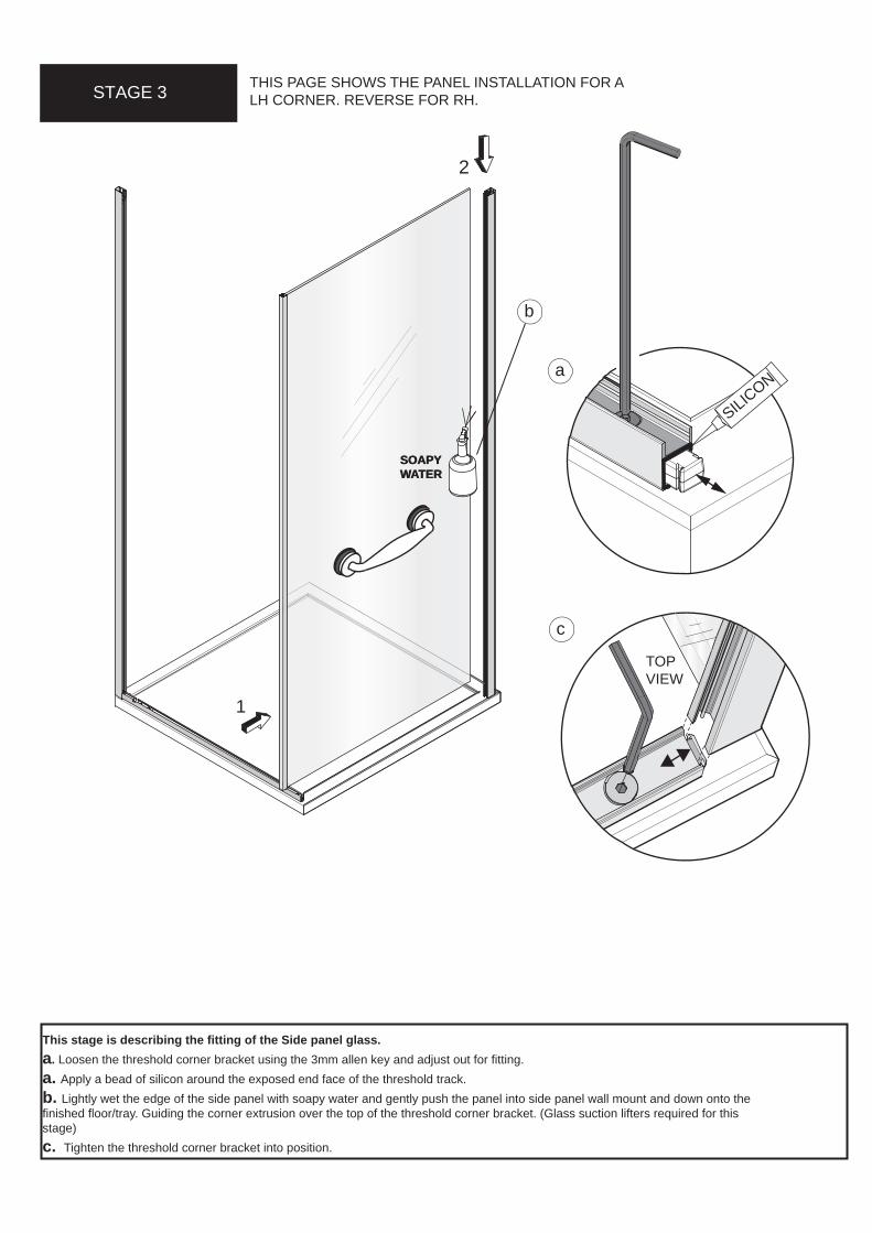
STAGE 3 THIS PAGE SHOWS THE PANEL INSTALLATION FOR A LH CORNER. REVERSE FOR RH.
SILICON
2
1
TOPVIEW
SOAPY WATER
c
a
This stage is describing the fitting of the Side panel glass.a. Loosen the threshold corner bracket using the 3mm allen key and adjust out for fitting. a. Apply a bead of silicon around the exposed end face of the threshold track.b. Lightly wet the edge of the side panel with soapy water and gently push the panel into side panel wall mount and down onto the finished floor/tray. Guiding the corner extrusion over the top of the threshold corner bracket. (Glass suction lifters required for this stage)c. Tighten the threshold corner bracket into position.
SOAPY WATER
b

THIS PAGE SHOWS THE PANEL INSTALLATION FOR A LH CORNER. REVERSE FOR RH.
STAGE 4
SOAPY WATER
1
2
This stage is describing the fitting of the fixed panel for a LH Corner, reverse for RH Corner. Before fitting the fixed glass panel adjust the threshold extrusion so that the side panel is at right angles to the threshold extrusion. Loosen the threshold adjuster and lightly tighten in position as required.a. Apply a bead of silicon along the outer inside edge of the threshold extrusion in the recess provided up to the cut-out where the fixed panel will be fitted.b. Remove and set aside the panel stop fixing screws from the threshold extrusion. c. Make sure the wall mount glass guard is pushed up fully to allow the glass to easily slot into the wall mount. Lightly wet the edge of the fixed panel with soapy water and gently lower the panel down into the threshold extrusion first then along into the wall mount.d. As a guide the end of the edge of the fixed panel glass and extrusion should be positioned inline with the start of the cut out in the threshold track, further slight adjustments may be required during the fitting of the door. Fix into position using the previously removed screw.
x 2
b
d
OUTSIDE FACE
SILICON
a
c
WALL MOUNTGLASS GUARD

This stage is describing the fitting of the closure panel for a LH Corner, reverse for RH Corner. a. Apply a bead of silicon along the outer inside edge of the threshold in the recess provided. b. Apply a bead of silicon in the corner extrusion as shown, down the full length of the corner extrusion.c. Remove and set aside the panel stop fixing screws from the threshold extrusion.
d. Gently lower the panel down into the threshold extrusion first then along into the corner panel extrusion, the extrusion on the bottom of the closure panel is offset, the exposed glass edge fits into to the corner extrusion.e. As a guide the end of the edge of the fixed panel glass and extrusion should be positioned inline with the start of the cut out in the threshold track, further slight adjustments may be required during the fitting of the door. Fix into position using the previously removed screw.
STAGE 5 THIS PAGE SHOWS THE PANEL INSTALLATION FOR A LH CORNER. REVERSE FOR RH.
a
SILICON
OUTSIDEFACE
INSIDEVIEW
d
b
SILICON
x 2c e
TAPE
TAPE

THIS IMAGE SHOWS THE ASSEMBLY OF THE HEADRAIL FOR A LH DOOR. ROTATE HEADRAIL 180° FOR RH DOOR.
STAGE 6
x 2
IMPORTANTx 2
x 2
a
c
d
This stage is describing the fitting of the Top Track.a. Loosen the fixings in the headrail adjuster to allow the adjuster to move freely in and out. Lower the top track into position, ensuring the tongue on the headrail adjuster fit down into the back of the wall mounts. Using a long spirit level align the upper and lower pivot points by adjusting the headrail left or right. Re-tighten the fixing in the headrail adjuster to fix in position. b. Fix the Corner frame fixing to the Corner frame using the pre-assembled screw.c. Important - tighten the top track locking screws underneath the top track on fixed panel wall mount to fix the top track to the wall mount.d. Fit he wall mount top cap (supplied in the kit of parts) to the top of the wall mount.
3mm
b 4mm

STAGE 7
b
a
c
This stage is describing the fitting of the Door.a. Lift the door and carefully guide the lower pivot block pin into the pivot block fitted to the threshold track.b. From behind guide the upper pivot block pin fixed to the headrail into the cup in the pivot block fitted to the top of the door.c. Rotate the pivot block disc with the socket csk screw 180° so that it secures the door in position. Tighten the socket csk screw.d. Disassemble the handle by unscrewing the 2 x M5 x 14 Csk socket screws. Place the glass washers either side of the 2 holes in the door glass. Re-assemble the handle to the glass and tighten into position with the grooved surfaces on the handle on the underside.
3mm
HANDLEd
GROOVESON UNDERSIDE

STAGE 8
BRACE FIXINGSCREW
b
a
This stage is describing the fitting of the side panel brace
a. Fit the Corner brace by locating the top cap into the side panel wall mount, adjust as required.b. Remove the brace fixing screw at the end of the brace bar and push fit the cap into the end of the top track, fix into position using the brace fixing screw. Insert the screw cover into front face of top track (supplied in kit of parts).

FIXED PANEL
STAGE 9
DOORADJUST
UNLOCK
IMPORTANTLOCK
BACK OF DOOR
b
c
d
This stage is describing the Door adjustment.a. Fit the door closure seal to the back of the door. The door closure seal can be adjusted away from the edge of the door to improve sealing with the fixed panel or the fixed panel can be adjusted at the top to the seal. Important. The inward/outward seal requires sufficient compression to the fixed panel glass. When initially opening the door both inwards and outwards the seal may deform unevenly and can catch the fixed panel. Allow the seal to take a set in the closed position for 12 -24 hrs. Open the door inwards and outwards adjust as required ensuring the seals works effectively for both directions of movement.
b. Temporarily fit the magnetic closure panel seal to the edge of the closure panel. Check the polarity of the magnet is correct with the magnet on the edge of the door. This seal can be adjusted away from the edge of the fixed panel to meet the door magnetic seal or the closure panel can be adjusted at the top to the door. Check there are no gaps between the door and magnetic closure panel seal.
c. To adjust the door left to right at the upper pivot point, loosen the socket cap screw in the top of the headrail by one turn only and adjust the door as required.
d. To adjust the door up and down at the lower pivot point, firstly loosen the locking screw in the lower pivot block. Then using the spanner (supplied in the kit of parts) wind the nut at the base of the pivot block anti-clockwise to raise the door upwards. Important - Re-tighten locking screw
2mm
IN/OUTWARD OPENING DOOR SEAL
(DOOR SHOWN IN OUTWARDOPEN POSITION)
a

STAGE 10
SILICO
N
SILI
CON
SILICO
N
SILICON
INSIDECAP
a
b
c
d
e
This stage is describing the fitting of the covers and caps.a. Apply a continuous bead of silicon all around the inside of the troughs in the threshold track between the edge of the fixed panel and the lower pivot block and between the other side of the lower pivot block and edge of the closure fixed panel, as shown above.b. Fit the two covers either side of the lower pivot block into the threshold track, so that the face of the covers is firmly pressed against the face of the lower pivot block and ensure the slope on the cover is facing inward. c. Apply a bead of silicon all around the inside of the recess in the threshold track where the threshold cover caps are to be fitted, from the edge of the threshold cover all the way around to the edge of the fixed glass panel. Fit the threshold cover caps (supplied in the kit of parts), with the slope facing inwards. d. Fit the upper pivot block covers (supplied in the kit of parts) over both sides of the upper pivot block.e. Fit the lower pivot block covers (supplied in the kit of parts) over both sides of the lower pivot block, note: the inner lower pivot block has a leg that should be pointing downwards.f. Fit the handle cover caps, press firmly into the ends of the handle.
x 2SILICON
SLOPEINWARDS
SLOPEINWARDS
FIXED PANEL
f

SILICON
DOOR(OPEN)
INSIDE VIEW
SILICO
N
SILICON
c
SILICONSILICON
STAGE 11
SILICON
SILICON
ab
d d
e
SILICON
SILICON
100mm
SILICON
MAGNETICSEAL
(FACTORYFITTED)
DOOR(OPEN)
FLU
SH
TOP
VIE
W
DOOR
SILICON
SILICON
100mmd
100mm
SILICON
This stage is describing the final fitting of the Seals and Silicon a. Fit the door horizontal seals to the bottom of the door, ensuring that the ends of the seal are firmly pressed up against the side of the lower pivot block on both sides. The horizontal seal deflector faces inwards. Adjust the Horizontal door seals down as required to meet the threshold. Pull off the vertical seal at the bottom on the pivot side and apply a bead of silicon sealant at the end of the horizontal seal, refit the vertical seal. Apply a small bead of silicon to the joints where the horizontal seals meet the inside pivot block cap.b. The end of the horizontal seal must be flush with the edge of the door. Apply a bead of silicon sealant between the bottom of the door and the horizontal seal, clean the silicon flush with the door edge.c. Pull off the closure panel vertical magnetic seal at the bottom. Apply a bead of silicon along the top of the threshold cover cap and vertical edge of the glass panel and refit the magnetic seal to the edge of the glass.d. Apply a thin bead of silicon along the bottom edge of both the wall mounts and all the way up the outside of both the wall mounts and the tiles. Apply a thin bead all the way along the threshold between the extrusion and finished floor surface/tray and the side panel glass where it meets the finished floor surface/tray. Continue around the joint where the threshold joins the wall mounts and also 100mm up on the outside where the wall mount and glass meet. Continue the silicon around the corner joint where the threshold meets the corner extrusion and also 100mm up on the outside where the corner extrusion and glass meet.e. Apply a bead of silicon on the outside around the joints between the threshold cover caps and threshold extrusion. Masking tape can be used to achieve a tidy edge to the sealant. Remove the masking tape immediately and allow the silicon to cure for 24 hours before using the shower.

PARTS LIST
20
1
PIVOT DISK KIT OF PARTS QTYPART NoDESCRIPTION
18440 A SILVERDECORATIVE PIVOT DISK WITH SEAL38252 A SILVERDECO DISK COVER RING18269 A SILVERDECO DISK COVER RING WITH CUT OUT28400 A SILVERDECORATIVE HANDLE CAP28582 AFDIN O-Ring 0140-2058652 A SILVERDECORATIVE PIVOT DISK14682 AFMTK1 PIVOT & QUINT DISK DISPLAY PACK11005 CHROMEMATKI CHROME EMBLEM
ITEM*747576
*7778
*798081
192
43
34
35
36
10
22
48
50
54
37
47
52
75
79
372 4
76
2975
74
71
79
77
70
66
62
619
21
10
71
PARTS LIST
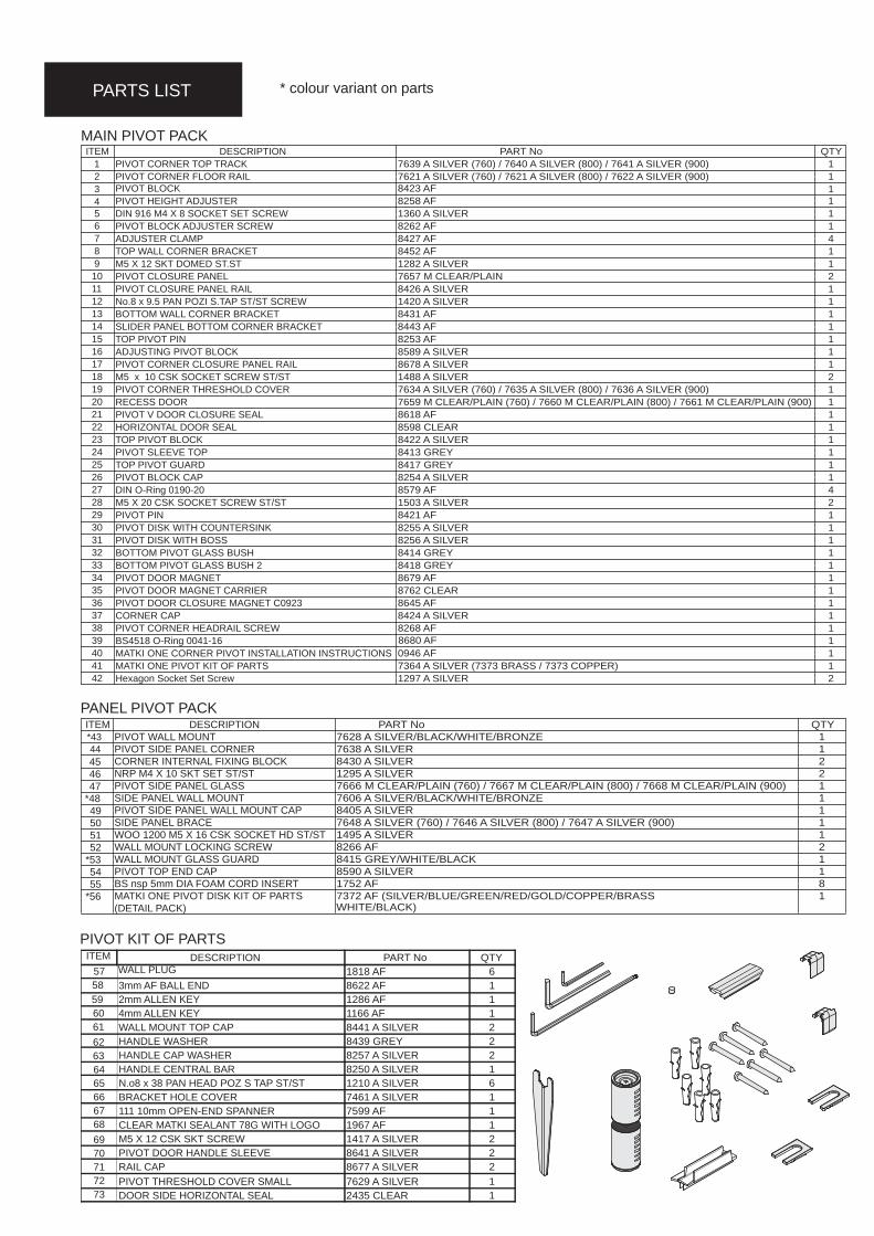
MAIN PIVOT PACK
* colour variant on parts
PANEL PIVOT PACK
PIVOT KIT OF PARTSQTYPART NoDESCRIPTION
61818 AFWALL PLUG18622 AF3mm AF BALL END11286 AF2mm ALLEN KEY11166 AF4mm ALLEN KEY28441 A SILVERWALL MOUNT TOP CAP28439 GREYHANDLE WASHER28257 A SILVERHANDLE CAP WASHER18250 A SILVERHANDLE CENTRAL BAR61210 A SILVERN.o8 x 38 PAN HEAD POZ S TAP ST/ST17461 A SILVERBRACKET HOLE COVER17599 AF111 10mm OPEN-END SPANNER11967 AFCLEAR MATKI SEALANT 78G WITH LOGO21417 A SILVERM5 X 12 CSK SKT SCREW28641 A SILVERPIVOT DOOR HANDLE SLEEVE28677 A SILVERRAIL CAP
ITEM
6061626364656667686970717273
17629 A SILVERPIVOT THRESHOLD COVER SMALL12435 CLEARDOOR SIDE HORIZONTAL SEAL
QTYPART NoDESCRIPTIONITEM17639 A SILVER (760) / 7640 A SILVER (800) / 7641 A SILVER (900) PIVOT CORNER TOP TRACK117621 A SILVER (760) / 7621 A SILVER (800) / 7622 A SILVER (900) PIVOT CORNER FLOOR RAIL213 8423 AFPIVOT BLOCK
4 18258 AFPIVOT HEIGHT ADJUSTER
611360 A SILVERDIN 916 M4 X 8 SOCKET SET SCREW
718262 AFPIVOT BLOCK ADJUSTER SCREW
848427 AFADJUSTER CLAMP
918452 AFTOP WALL CORNER BRACKET
1011282 A SILVERM5 X 12 SKT DOMED ST.ST
1127657 M CLEAR/PLAINPIVOT CLOSURE PANEL
1218426 A SILVERPIVOT CLOSURE PANEL RAIL
1311420 A SILVERNo.8 x 9.5 PAN POZI S.TAP ST/ST SCREW
1418431 AFBOTTOM WALL CORNER BRACKET
1518443 AFSLIDER PANEL BOTTOM CORNER BRACKET
1618253 AFTOP PIVOT PIN
1718589 A SILVERADJUSTING PIVOT BLOCK
1818678 A SILVERPIVOT CORNER CLOSURE PANEL RAIL
1921488 A SILVERM5 x 10 CSK SOCKET SCREW ST/ST
2017634 A SILVER (760) / 7635 A SILVER (800) / 7636 A SILVER (900)PIVOT CORNER THRESHOLD COVER
2117659 M CLEAR/PLAIN (760) / 7660 M CLEAR/PLAIN (800) / 7661 M CLEAR/PLAIN (900)RECESS DOOR
2223
18618 AFPIVOT V DOOR CLOSURE SEAL
24
18598 CLEARHORIZONTAL DOOR SEAL
25
18422 A SILVERTOP PIVOT BLOCK
26
18413 GREYPIVOT SLEEVE TOP
27
18417 GREYTOP PIVOT GUARD
28
18254 A SILVERPIVOT BLOCK CAP
29
48579 AFDIN O-Ring 0190-20
30
21503 A SILVERM5 X 20 CSK SOCKET SCREW ST/ST
31
18421 AFPIVOT PIN
32
18255 A SILVERPIVOT DISK WITH COUNTERSINK
33
18256 A SILVERPIVOT DISK WITH BOSS
34
18414 GREYBOTTOM PIVOT GLASS BUSH
35
18418 GREYBOTTOM PIVOT GLASS BUSH 2
36
18679 AFPIVOT DOOR MAGNET
37
18762 CLEARPIVOT DOOR MAGNET CARRIER
38
18645 AFPIVOT DOOR CLOSURE MAGNET C0923
39
18424 A SILVERCORNER CAP
40
18268 AFPIVOT CORNER HEADRAIL SCREW
41
1
BS4518 O-Ring 0041-16
42
10946 AFMATKI ONE CORNER PIVOT INSTALLATION INSTRUCTIONS
*43
17364 A SILVER (7373 BRASS / 7373 COPPER)MATKI ONE PIVOT KIT OF PARTS21297 A SILVERHexagon Socket Set Screw
QTYPART NoDESCRIPTIONITEM17628 A SILVER/BLACK/WHITE/BRONZEPIVOT WALL MOUNT
4517638 A SILVERPIVOT SIDE PANEL CORNER
4628430 A SILVERCORNER INTERNAL FIXING BLOCK21295 A SILVERNRP M4 X 10 SKT SET ST/ST17666 M CLEAR/PLAIN (760) / 7667 M CLEAR/PLAIN (800) / 7668 M CLEAR/PLAIN (900)PIVOT SIDE PANEL GLASS17606 A SILVER/BLACK/WHITE/BRONZESIDE PANEL WALL MOUNT18405 A SILVERPIVOT SIDE PANEL WALL MOUNT CAP17648 A SILVER (760) / 7646 A SILVER (800) / 7647 A SILVER (900)SIDE PANEL BRACE11495 A SILVERWOO 1200 M5 X 16 CSK SOCKET HD ST/ST28266 AFWALL MOUNT LOCKING SCREW18415 GREY/WHITE/BLACKWALL MOUNT GLASS GUARD18590 A SILVERPIVOT TOP END CAP81752 AFBS nsp 5mm DIA FOAM CORD INSERT1 MATKI ONE PIVOT DISK KIT OF PARTS
(DETAIL PACK)
47*4849505152
*535455
*56
5758
8680 AF
7372 AF (SILVER/BLUE/GREEN/RED/GOLD/COPPER/BRASSWHITE/BLACK)
44
59
5

Matki Glass Guard Easy Clean Surface Protection (optional) and General Cleaning Guide
Cleaning InstructionsMatki Glass Guard allows water to form minute beads which easily trickle off the surface of the glass. This makes the glass easier to clean - the glass does not need to be cleaned as frequently, but it does require occasional maintenance. As less cleaning is required the use of detergents can be minimised thus helping to protect the environment. The lifespan of the Matki Glass Guard is dependant on the frequency of use of the shower and the degree of water hardness.
The combination of alkaline materials and humidity affects glass in an extremely aggressive way. Do not use bleach, alkaline, acid-based or aggressive and abrasive glass cleaners, detergents or household cleaning products on the glass or frames.
We recommend that glass is washed down with clean water and a soft clean cloth or sponge and dried off with a microfibre cloth.
The special coating is only present on the inside of the glass.
Matki Glass Guard is guaranteed for 2 years provided that the guidelines and cleaning instructions are followed.
Aluminium and Chrome parts should be cleaned with a mild non scratch household cleaner and a soft cloth or sponge.
Do not use acidic-based descaler products or products which are unsuitable for cleaning enamelled surfaces, including abrasive cleaners or cleaners containing bleach or solvents, as the products will effect the anodised framework. Under no circumstances use cleaners with a pH level exceeding 8.
Matki does not recommend the use of 'Leave-on' shower cleaners on Matki Glass Guard Products.
Water Softeners and Glass Guard - Certain types of water softeners increase the alkalinity of the water due to a carry-over of Chloride during re-generation which can cause aggressive water spots on both untreated and Glass Guarded glass. If using a water softener we recommend a two-cylinder machine with automatic re-generation instead of a timer. If a single-cylinder water softener with timer is already installed it is recommended that after each shower excess water is removed from the glass with a squeegee or with a micro-fibre cloth.
MAINTENANCE
Flash Bathroom Spray or Cif Bathroom Spray can be used on Matki Products.Read manufacturers label before using any cleaning materials.
IMPORTANTMatki Glass Guard is guaranteed for 2 years. It is essential that the cleaning instructions are followed in order to maintain the hydrophobic properties of the glass coating. In the event of the failure to comply in any way with these instructions, any warranty or guarantee will be null and void.
BLEACH
WHITE SPIRIT
Wash down with clean warm water and a soft clean cloth or sponge.
Do not use bleach, alkaline or acid-based, aggressive or abrasive cleaning products.
MATKI PLC, CHURCHWARD ROAD, YATE, BRISTOL, BS37 5PLTELEPHONE:01454 328816 (AFTER SALES) FAX:01454 328821 EMAIL: [email protected]
13Matki PLC, Churchward Road, Yate,
Bristol BS37 5PL
EN 14428:2008+A1
Annual recommended maintenance - Matki recommend annually lubricating the barrel of the hinge with a lubricating spray such as WD-40 to remove dust build-up and to aid the movement of the hinge.