Materials Process and Applications of Single Grain...
17
IEEE/CSC & ESAS EUROPEAN SUPERCONDUCTIVITY NEWS FORUM, No. 19, January 2012 Page 1 of 17 Materials Process and Applications of Single Grain (RE)-Ba-Cu-O Bulk High-temperature Superconductors Beizhan Li, Difan Zhou, Kun Xu, Shogo Hara, Keita Tsuzuki, Motohiro Miki, Brice Felder, Zigang Deng and Mitsuru Izumi* Laboratory of Applied Physics, Department of Marine Electronics and Mechanical Engineering, Tokyo University of Marine Science and Technology (TUMSAT), 2-1-6, Etchu-jima, Koto-ku, Tokyo 135-8533, Japan *E-mail: [email protected] Abstract - This paper reviews recent advances in the melt process of (RE)-Ba-Cu-O [(RE)BCO, where RE represents a rare earth element] single grain high-temperature superconductors (HTS), bulks and its applications. The efforts on the improvement of the magnetic flux pinning with employing the top-seeded melt-growth process technique and using a seeded infiltration and growth process are discussed. Which including various chemical doping strategies and controlled pushing effect based on the peritectic reaction of (RE)BCO. The typical experiment results, such as the largest single domain bulk, the clear TEM observations and the significant critical current density, are summarized together with the magnetization techniques. Finally, we highlight the recent prominent progress of HTS bulk applications, including Maglev, flywheel, power device, magnetic drug delivery system and magnetic resonance devices. Preprint of plenary SCC paper submitted to Physica C (should be cited accordingly) Submitted to ESNF November 30, 2011; accepted Dec. 6, 2011. Reference No. CR24; Category 3. Keywords – rare earth, cuprate, high-temperature superconductor, HTS, bulk superconductor, melt growth process, flux pinning, MAGLEV, MRI, Flywheel, Motor I. INTRODUCTION Following the discovery of YBa 2 Cu 3 O 7-ƒΒ [1], (RE)Ba 2 Cu 3 O 7-ƒΒ , i.e., (RE)BCO or RE-123 (RE = rare earth element or Y) bulk high-temperature superconductors (HTS) have attracted the worldwide study for their ability to trap large magnetic flux density of 17 T at 29 K [2] and 3 T at 77 K [3]. Those trapped fields are obviously higher than those of conventional permanent magnets and can be potentially used in a wide range of
Transcript of Materials Process and Applications of Single Grain...
IEEE/CSC & ESAS EUROPEAN SUPERCONDUCTIVITY NEWS FORUM, No. 19, January 2012
Page 1 of 17
Materials Process and Applications of Single Grain (RE)-Ba-Cu-O Bulk High-temperature Superconductors
Beizhan Li, Difan Zhou, Kun Xu, Shogo Hara, Keita Tsuzuki, Motohiro Miki, Brice
Felder, Zigang Deng and Mitsuru Izumi*
Laboratory of Applied Physics, Department of Marine Electronics and Mechanical
Engineering, Tokyo University of Marine Science and Technology (TUMSAT), 2-1-6,
Etchu-jima, Koto-ku, Tokyo 135-8533, Japan
*E-mail: [email protected]
Abstract - This paper reviews recent advances in the melt process of (RE)-Ba-Cu-O [(RE)BCO,
where RE represents a rare earth element] single grain high-temperature superconductors (HTS),
bulks and its applications. The efforts on the improvement of the magnetic flux pinning with
employing the top-seeded melt-growth process technique and using a seeded infiltration and growth
process are discussed. Which including various chemical doping strategies and controlled pushing
effect based on the peritectic reaction of (RE)BCO. The typical experiment results, such as the
largest single domain bulk, the clear TEM observations and the significant critical current density,
are summarized together with the magnetization techniques. Finally, we highlight the recent
prominent progress of HTS bulk applications, including Maglev, flywheel, power device, magnetic
drug delivery system and magnetic resonance devices.
Preprint of plenary SCC paper submitted to Physica C (should be cited accordingly)
Submitted to ESNF November 30, 2011; accepted Dec. 6, 2011. Reference No. CR24; Category 3.
Keywords – rare earth, cuprate, high-temperature superconductor, HTS, bulk superconductor, melt
growth process, flux pinning, MAGLEV, MRI, Flywheel, Motor
I. INTRODUCTION
Following the discovery of YBa2Cu3O7-ƒΒ[1], (RE)Ba2Cu3O7-ƒΒ, i.e., (RE)BCO or
RE-123 (RE = rare earth element or Y) bulk high-temperature superconductors (HTS)
have attracted the worldwide study for their ability to trap large magnetic flux density of
17 T at 29 K [2] and 3 T at 77 K [3]. Those trapped fields are obviously higher than
those of conventional permanent magnets and can be potentially used in a wide range of
--
Text Box
Preprint of plenary SCC paper submitted to Physica C (should be cited accordingly)

IEEE/CSC & ESAS EUROPEAN SUPERCONDUCTIVITY NEWS FORUM, No. 19, January 2012
Page 2 of 17
sustainable engineering applications. Many prototype applications, such as fault current
limiters, motors and generators, flywheel batteries, maglev and magnetic separation
systems, have been designed [4-6]. For those applications, a very important parameter is
the critical current density Jc, which determines the maximum electric current that is
flowing without energy dissipation. However, typical values of Jc for bulk single grain
materials are nearly two orders of magnitude lower than those achieved in thin-films or
coated conductors. Due to short coherence lengths of HTS, which are 2-4 nm for YBCO
below 77 K, various nano-sized structural disorder sources such as inclusions can be
effective pinning centers. They prevent thermally activated giant flux motion, thereby
resulting in large super-current and a high irreversibility field [6-8]. Nevertheless, it is
not an easy task to implant the nano-sized pinning centers in the bulk. To improve Jc via
material processing, including the control of crystal chemistry, melt growth, flux
pinning, etc., is still a challenging task. Previous review articles on this topic are
available in [9-17].
We briefly describe the recent progress, discuss the characterization of their
microstructure and superconducting properties, and outline the prominent and emerging
applications that incorporate bulk (RE)BCO materials.
II. DEVELOPMENT OF MELT TEXTURED (RE)BCO BULK
SUPERCONDUCTORS
The trapped field BT ∝ Jc × R, where R is the radius of the single domain, and Jc are
approximately proportional to the interface area between the matrix and inclusions [16,
18]. Hence, introducing nano-sized defects and attaining large grain size are effective
ways to get large BT. For the improvement of Jc, one of the techniques is the addition of
second phase particles into the superconducting matrix. To obtain large single grains,
the most common method so far is to use the top seeded melt texture (TSMG) technique.
A BT near 10 T may be possible at 77 K if proper chemical pinning centers are created
[19].
A. Melt Processing Techniques
Since the initiation of melt processing, significant progress has been achieved in the

IEEE/CSC & ESAS EUROPEAN SUPERCONDUCTIVITY NEWS FORUM, No. 19, January 2012
Page 3 of 17
development of melt texturing methods. Early stage explorations are found in ref. [20].
Nowadays, two kinds of melt processes are adopted based on the peritectic reaction of
(RE)BCO: one is TSMG technique, the other is the infiltration and growth (IG) process.
Correspondingly, the seeding technique has been developed to allow the so-called batch
bulk process and controlled multi-domain bulk growth.
The TSMG Technique
The TSMG technique has been developed for the fabrication of large grain (RE)BCO
bulk objects above the peritectic temperature Tp. In this reaction, solid (RE)BCO
decomposes to form solid RE-211 and BaCuO-based liquid. A single grain is formed by
cooling a molten (RE)BCO sample slowly through Tp. The process is as follows. The
starting materials of (RE)BCO, RE-211, Ag2O, Pt or CeO2, etc., are thoroughly mixed.
The mixture is uniaxially pressed into a pellet. Generally, the Y-stabilized ZrO2 rods are
used to support the pellet. A seed is placed on the top surface of the pre-sintered pellet
(hot seeding method) or placed there at room temperature before melt processing (cold
seeding method) to nucleate the growth of a single grain. The arrangement is then melt
grown in a reduced oxygen partial pressure (oxygen controlled melt growth process,
OCMG).
Fig. 1. Single domain bulk disks fabricated by employing the TSMG technique. The large
disk has a diameter of 150 mm, the small one has a diameter of 60 mm. Inset illustrates the
flux distributions in the large disk (courtesy of Hidekazu Teshima and Mitsuru Morita,
Nippon Steel Corporation).
As the ionic radius of all RE3+ is close to Ba2+, the RE1+xBa2-xCu3Oy solid solutions
may form during melt process. The OCMG process can suppress the solid solution
formation and thus increase Tc [21]. However, the OCMG process takes longer time and

IEEE/CSC & ESAS EUROPEAN SUPERCONDUCTIVITY NEWS FORUM, No. 19, January 2012
Page 4 of 17
involves higher cost than the air process. Therefore, the air process is preferentially
adopted, especially for Gd-123. With adding Ba-rich compounds and employing
Ar-post annealing (ArPA), the (RE)BCO superconductors are fabricated with high
quality. Single-domain disks fabricated by optimized TSMG technique have been
reported with diameters up to 140 mm [22-24]. A recent result (Nippon Steel
Corporation, Japan) shows a diameter of 150 mm with a homogeneous flux distribution
and a trapped flux density of over 0.8 T at 87 K, as shown in Figure 1. The TSMG
technique has the disadvantage of easy coarsening, large shrinkage and liquid outflow.
Macroscopic cracks and pores are also easy to form in the melt growth. The chemical
composition of the final product is generally inhomogeneous.
The Seeded Infiltration and Growth (IG) Process
The IG process involves the infiltration of liquid phases into a pellet of RE-211 with
subsequent reacting to form (RE)BCO below Tp. The IG process allows near arbitrary
shape fabrication with negligible shrinkage and distortion [24, 25] of, e.g., hollow
cylinders [26], superconducting foams [27] and fabrics [28, 29]. The major advantage of
the IG process compared to the TSMG process is the ability to provide fine-sized
spherical RE-211 precipitates in the (RE)BCO matrix, even without addition of
compounds such as Pt and CeO2 [30-32]. It makes the IG process attractive. With a
modified IG process, the value of Jc is up to 230 kA/cm2 under zero-field and 10
kA/cm2 up to 7 T at 77 K in YBCO [33]. However, the IG process has the disadvantage
that the uniformity of microstructure and Jc is uncertain [31].
Seed Techniques
For both TSMG and IG process, a choice of the seed crystal is an important factor. It
should have the lattice parameters close to those of (RE)BCO and remain stable during
the whole melt process. As Nd-123 has the highest melting point (1068 ˚C) in the
RE-123 family, Nd-123 crystals are usually employed as seeds for growth of other
(RE)BCO bulk superconductors [14]. However, because the Tp of Nd-123 is not high
enough, the kind of species which could be seeded in the (RE)BCO are limited [34].
The Mg-doped ( > 0.5 wt.% ) Nd-123 has the Tp by 20 ˚C higher than the Tp of pure
Nd-123 [35]. Recently, a superheating phenomenon was found in epitaxial films on
(RE)BCO/substrate (substrate = MgO, LaAlO3 or SrTiO3). The film can endure a higher
temperature than the corresponding single crystal. Yan et al. reported that the
Nd-123/MgO film has a superheating upper limit around 1098 ˚C [36]. Xu et al.
claimed the YBCO buffered Nd-123/YBCO/MgO film can even endure temperatures

IEEE/CSC & ESAS EUROPEAN SUPERCONDUCTIVITY NEWS FORUM, No. 19, January 2012
Page 5 of 17
up to 1120 ˚C [37].
B. Artificial Pinning Centers, Microstructures and Superconducting Properties
The short coherence lengths and large anisotropies of the HTS materials generally lead
to an intrinsic weak pinning of flux lines [39]. Such problem can be reduced by creating
correlated defects, e.g., columnar defects by irradiation [7], ion substitutions [38, 40,
41], and addition of second phases [42, 43]. As the weak pinning centers originate from
the defects of crystals, an evolution method is to make artificial pinning sites by ionic
substitutes. For (RE)BCO system, on the one hand, it is generally recognized that Tc
strongly depends on the oxygen content, which directly affects the carrier concentration
and RE1+xBa2-xCu3Oy solid solutions [21]. On the other hand, as shown in Figure 2(a),
experiments show that Ba2+ site, CuO2 planes and CuO chains can be substituted with
other ions. Occasionally, this leads not only to increased pinning site densities, but also
to an improvement of superconducting properties. For example, Ba-rich additions
suppress RE1+xBa2-xCu3Oy solid solutions, which lead to improved Jc [44, 45]. Similar
effect by dilute doping to the CuO2 plane was found in zinc- or nickel-doped YBCO
bulk [46, 47]. Subsequently, as shown in Figure 2(b), Ishii et al. [38] found that local
disorder in CuO chains by dilute impurity doping is a more promising way to improve
Jc than impurity doping in Ba sites or CuO2 planes. Especially in RE3+ mixed binary,
ternary and quaternary systems one can attain higher density of effective pinning centers
by adjusting the ratio of RE elements [48, 49].
Fig. 2. (a) Illustration of the ionic substitutions. (J. Shimoyama, The University of Tokyo);
(b) Comparison of Jc for various ion site substitutions [38].
According to the great compatibility of (RE)BCO system, many kinds of additions
IEEE/CSC & ESAS EUROPEAN SUPERCONDUCTIVITY NEWS FORUM, No. 19, January 2012
Page 6 of 17
are able to be incorporated in the matrix to act as pinning centers. It is well known that
second phases of RE-211 or RE-422 enhance flux pinning. Among them, Gd-211 was
found to produce the highest flux pinning. The Tp of Gd-123 is the lowest of all the
(RE)BCO compounds. Thus, Gd-211 can nucleate at the lowest temperature, which is
probably the reason for the typically small size of inclusions. The optimum content of
Gd-211 is around 35 mol%.
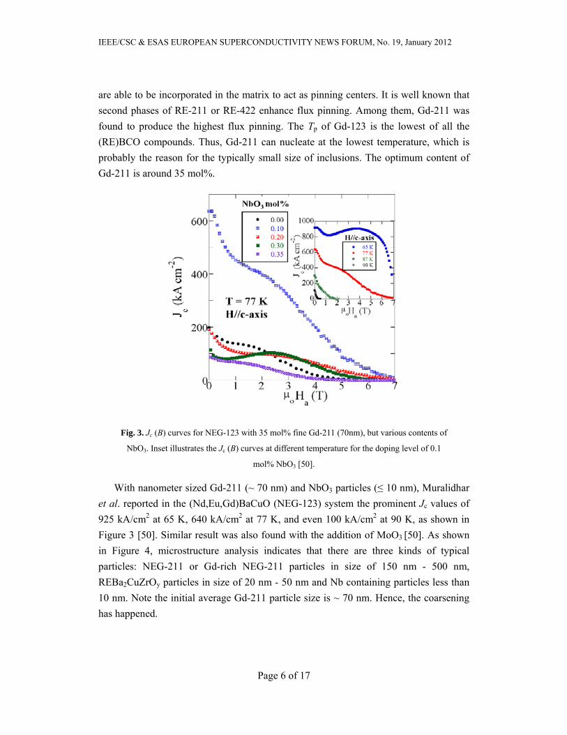
Fig. 3. Jc (B) curves for NEG-123 with 35 mol% fine Gd-211 (70nm), but various contents of
NbO3. Inset illustrates the Jc (B) curves at different temperature for the doping level of 0.1
mol% NbO3 [50].
With nanometer sized Gd-211 (~ 70 nm) and NbO3 particles (≤ 10 nm), Muralidhar
et al. reported in the (Nd,Eu,Gd)BaCuO (NEG-123) system the prominent Jc values of
925 kA/cm2 at 65 K, 640 kA/cm2 at 77 K, and even 100 kA/cm2 at 90 K, as shown in
Figure 3 [50]. Similar result was also found with the addition of MoO3 [50]. As shown
in Figure 4, microstructure analysis indicates that there are three kinds of typical
particles: NEG-211 or Gd-rich NEG-211 particles in size of 150 nm - 500 nm,
REBa2CuZrOy particles in size of 20 nm - 50 nm and Nb containing particles less than
10 nm. Note the initial average Gd-211 particle size is ~ 70 nm. Hence, the coarsening
has happened.

IEEE/CSC & ESAS EUROPEAN SUPERCONDUCTIVITY NEWS FORUM, No. 19, January 2012
Page 7 of 17
Fig. 4. TEM images of NEG-123 sample with 35 mol% Gd-211 (the initial average particle
size is 70 nm) (a), and 0.1 mol% MoO3 (b). The arrows point to some of the Mo based
nano-sized particles < 10 nm. The (c) and (d) images are of NEG-123 sample with 0.1 mol%
NbO3. The arrows point to some of the Nb based nano-sized particles < 10 nm. [50]
Fig. 5. TEM images of ZrO2 and SnO2 doped Gd-123 bulk: (a) shows a typical TEM image
of ZrO2 doped Gd-123 bulk. The typical nanometer-sized BaZrO3 particle is indicated by
blue circle. (b) A c-direction TEM image; insets illustrate the Zr element mapping. (c) A
typical TEM image of SnO2 doped Gd-123 bulk. The typical nanometer sized BaSnO3
particles are indicated by black lines. [55]

IEEE/CSC & ESAS EUROPEAN SUPERCONDUCTIVITY NEWS FORUM, No. 19, January 2012
Page 8 of 17
Hari Babu et al. studied in the YBCO system other interesting second phases,
namely RE2Ba4CuMOz (RE-2411, RE = Y, Sm or Gd, M = Nb, Ta, W, Mo, Zr, Hf, Ag,
etc.) [15, 51-53]. They found Y-2411 large particles consist of agglomerated clusters of
much smaller particles sized between 20 and 100 nm. Those nanometer particles can be
dispersed by Ba-Cu-O liquid and retain their size during the melt growth. A typical size
range of 20 to 50 nm was stably embedded in the YBCO matrix [52]. Hence, Jc has
been improved remarkably by the combined Y-2411 with Y-211 [15, 52]. However,
with different kinds of M ions, the properties of RE-2411 become different. Xu et al.
found a band structure with the alternative distribution of Gd-211 and Gd-2411 (M =
Mo) [54].
Fig. 6. Jc (B) curves at 77 K with B // c-axis of specimens which were cut from different
parts of the standard bulk and 0.05 wt.% Fe-B alloy doped bulk. The inset illustrates the cut
positions [56].
Pinning is optimized when the size of the defects approaches the coherence length
and when the areal number density of defects is on the order of (B/2) × 1011 cm-2, where
B is the applied magnetic field in tesla [6, 17]. Such a high density has been difficult to
achieve by material processing methods due to the coarsening of RE-211. Therefore,
based on the second phase of RE-211, the addition of a small amount of foreign
particles generally improves the pinning effect and Jc. Remarkable improvement of Jc
has been achieved with the additions of 0.1 mol% NbO3 as shown in Fig. 3. Experiment
shows that Zr, Zn, Sn, Nb, Mo, Ti, Hf, Fe, Al are energetically favourable for flux

IEEE/CSC & ESAS EUROPEAN SUPERCONDUCTIVITY NEWS FORUM, No. 19, January 2012
Page 9 of 17
pinning with a dilute doping level range from 0.1 mol% to 1 mol%. To clarify the
underlying nature of the enhancement in superconducting properties, systematic studies
on the microstructure have been performed. Xu et al. [55] studied the microstructure of
ZrO2, SnO2 and ZnO2 doped Gd-123 bulks by using TEM, as shown in Figure 5. They
found BaZrO3 and BaSnO3 particles in size of ~ 50nm formed in ZrO2 and SnO2 doped
samples and contributed to the δl pinning1 [56]. In contrast, doping of the bulk with
ZnO2 mainly contribute to the δTc pinning2 [56] due to the substitution of Cu sites by
Zn. As a result, Zn-rich compounds were not observed.
As can be seen from Figure. 4 and Figure. 5, the presence of particles several tens of
nanometer in size was always resulting in a particular supercurrent enhancement over a
wide temperature range [50]. To date, the mechanism of collaborative flux pinning by
the pinning structure with the particle size distribution ranging from microns to
nanometers is not clear, but there is no doubt that those random distributed defects are
very promising for practical applications.
Beside the single element doping, complex compound doping is also performed. Xu
et al. [57,58] found that magnetic Fe-B alloy doping is able to enhance Jc, as shown in
Fig 6, although Tc was suppressed significantly. Subsequently, Xu et al. reported [59]
the Fe-B alloy particles to have decomposed while ferromagnetic Fe3O4 was formed.
Tsuzuki et al. have compared the doping effect of Fe-B alloy and Fe2O3, and found
Fe-B alloy doping is superior to Fe2O3 doping for the enhancement of pinning in
Gd-123 bulk [60]. The issue of magnetic pinning is still under debate.
III. MAGNETIZATION TECHNIQUES
The trapped field of a bulk is not only determined by pinning centers, but also
correlated with the magnetization process. Generally, four magnetization methods can
be utilized: field-cooling (FC), zero-field cooling (ZFC), pulsed field magnetization
(PFM) and flux pumping (FP). To trap the maximum possible field BT, max, the required
applied field BA is, BA ≥ BT, max for FC, BA ≥ 2 BT, max for ZFC, and BA ~ 4 BT, max or
lower for pulsed ZFC. Using flux pumping full magnetization can be achieved with
peak fields of BA ~ 0.25 BT, max, by applying multiple cycles [19]. A variety of technical
issues have been done for the aim of effective magnetization and flux trapping. For
example, the PFM has been developed to generate the conical trapped field by 1The ƒΒl pinning is caused by fluctuations of the charge carrier mean free path near a lattice defect. 2The ƒΒTc pinning is caused by spatial fluctuations of the transition temperature Tc.
IEEE/CSC & ESAS EUROPEAN SUPERCONDUCTIVITY NEWS FORUM, No. 19, January 2012
Page 10 of 17
Sugimoto et al [61] and further developed for rotating machinery applications [62].
IV. APPLICATIONS OF BULK (RE)BCO MATERIALS
Bulk (RE)BCO superconductors are potentially applied to three general categories in
engineering, including levitation devices such as maglev, flywheels, seismic isolation,
rotating machines as motors and generators, and trapped flux devices (sputtering
systems, separators, drug delivery and nuclear magnetic resonance systems).
A. Magnetic Levitation
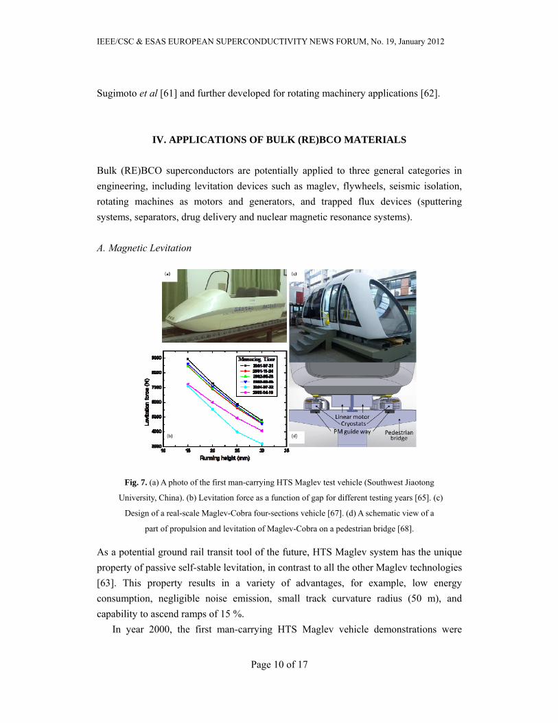
Fig. 7. (a) A photo of the first man-carrying HTS Maglev test vehicle (Southwest Jiaotong
University, China). (b) Levitation force as a function of gap for different testing years [65]. (c)
Design of a real-scale Maglev-Cobra four-sections vehicle [67]. (d) A schematic view of a
part of propulsion and levitation of Maglev-Cobra on a pedestrian bridge [68].
As a potential ground rail transit tool of the future, HTS Maglev system has the unique
property of passive self-stable levitation, in contrast to all the other Maglev technologies
[63]. This property results in a variety of advantages, for example, low energy
consumption, negligible noise emission, small track curvature radius (50 m), and
capability to ascend ramps of 15 %.
In year 2000, the first man-carrying HTS Maglev vehicle demonstrations were
IEEE/CSC & ESAS EUROPEAN SUPERCONDUCTIVITY NEWS FORUM, No. 19, January 2012
Page 11 of 17
successfully completed in China [64]. The vehicle is shown in Figure 7(a). Using
YBCO bulk magnets the vehicle has a levitation capability of 635 kg, and a lateral
restoring force of 198 kg. Both the reliability and stability of this vehicle were
demonstrated in longer-time operation, as shown in Figure 7(b) [65]. In the past decade,
similar work have been carried out in Germany, Russia, Brazil, Japan, Italy and other
countries [66]. Among these, a realistic vehicle called Maglev-Cobra stands out. Figure
7(c) show its external view (a photo) while Figure 7(d) is a somewhat schematic
drawing of the vehicle on a pedestrian bridge [67, 68].
B. Flywheel
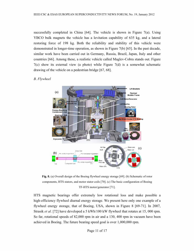
Fig. 8. (a) Overall design of the Boeing flywheel energy storage [69]. (b) Schematic of rotor
components, HTS stators, and motor stator coils [70]. (c) The basic configuration of Boeing
TF-HTS motor/generator [71].
HTS magnetic bearings offer extremely low rotational loss and make possible a
high-efficiency flywheel diurnal energy storage. We present here only one example of a
flywheel energy storage, that of Boeing, USA, shown in Figure 8 [69-71]. In 2007,
Strasik et al. [72] have developed a 5 kWh/100 kW flywheel that rotates at 15, 000 rpm.
So far, rotational speeds of 82,000 rpm in air and a 130, 400 rpm in vacuum have been
achieved in Boeing. The future bearing speed goal is over 1,000,000 rpm.
IEEE/CSC & ESAS EUROPEAN SUPERCONDUCTIVITY NEWS FORUM, No. 19, January 2012
Page 12 of 17
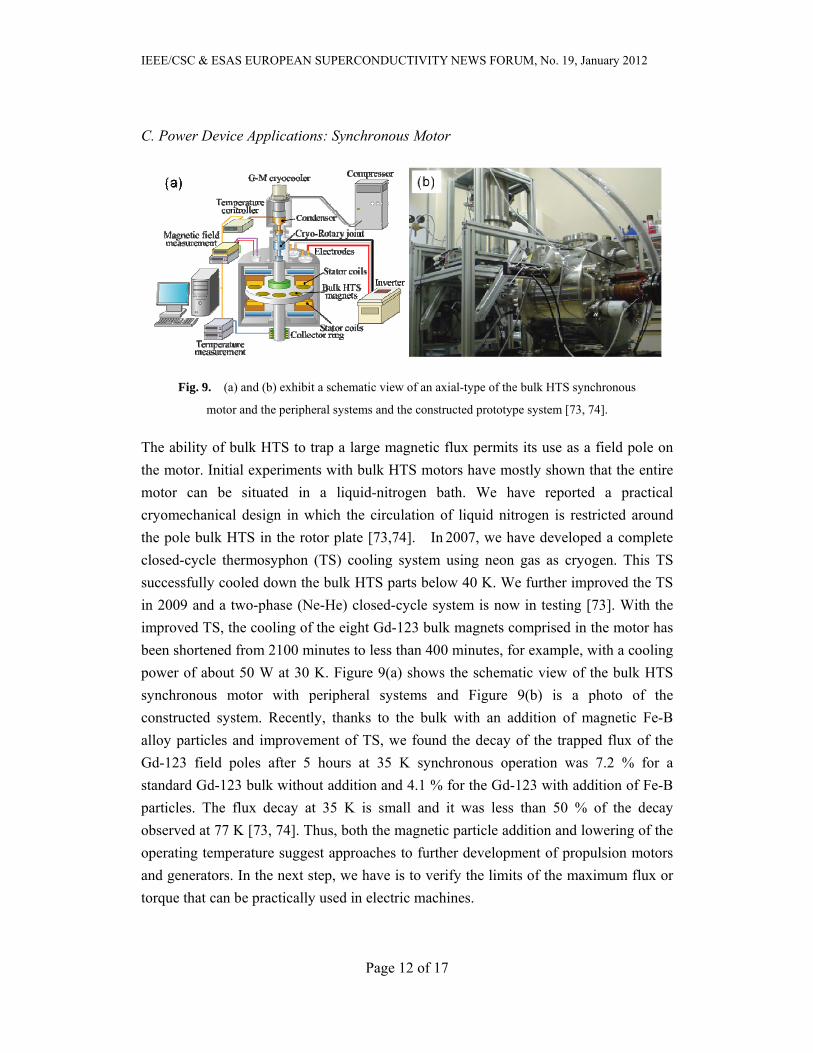
C. Power Device Applications: Synchronous Motor
Fig. 9. (a) and (b) exhibit a schematic view of an axial-type of the bulk HTS synchronous
motor and the peripheral systems and the constructed prototype system [73, 74].
The ability of bulk HTS to trap a large magnetic flux permits its use as a field pole on
the motor. Initial experiments with bulk HTS motors have mostly shown that the entire
motor can be situated in a liquid-nitrogen bath. We have reported a practical
cryomechanical design in which the circulation of liquid nitrogen is restricted around
the pole bulk HTS in the rotor plate [73,74]. In 2007, we have developed a complete
closed-cycle thermosyphon (TS) cooling system using neon gas as cryogen. This TS
successfully cooled down the bulk HTS parts below 40 K. We further improved the TS
in 2009 and a two-phase (Ne-He) closed-cycle system is now in testing [73]. With the
improved TS, the cooling of the eight Gd-123 bulk magnets comprised in the motor has
been shortened from 2100 minutes to less than 400 minutes, for example, with a cooling
power of about 50 W at 30 K. Figure 9(a) shows the schematic view of the bulk HTS
synchronous motor with peripheral systems and Figure 9(b) is a photo of the
constructed system. Recently, thanks to the bulk with an addition of magnetic Fe-B
alloy particles and improvement of TS, we found the decay of the trapped flux of the
Gd-123 field poles after 5 hours at 35 K synchronous operation was 7.2 % for a
standard Gd-123 bulk without addition and 4.1 % for the Gd-123 with addition of Fe-B
particles. The flux decay at 35 K is small and it was less than 50 % of the decay
observed at 77 K [73, 74]. Thus, both the magnetic particle addition and lowering of the
operating temperature suggest approaches to further development of propulsion motors
and generators. In the next step, we have is to verify the limits of the maximum flux or
torque that can be practically used in electric machines.

IEEE/CSC & ESAS EUROPEAN SUPERCONDUCTIVITY NEWS FORUM, No. 19, January 2012
Page 13 of 17
D. Magnetic Drug Delivery System (MDDS)
The MDDS is a technology to control the drug diffusion with the human body
quantitatively, both spatially and temporally. It prevents the medicine from diffusing
throughout the human body by selective transportation to the diseased part [75].
However, in the case of the accumulation of drug carrier ferromagnetic particles with
small guiding permanent magnet, it is difficult to accumulate the particles even at short
distances away from the magnet. Nishijima et al. [76] successfully made a MDDS by
employing Gd-123 bulk as strong magnet to control the drug delivery. The probability
of drug navigation to the desired direction was confirmed to be higher than 80 %.3
They studied the appropriate diameter of liposome and the number of encapsulated
ferromagnetic particles which can be controlled by the external magnetic force. Their
result shows that the size of magnetite particles should > 100 nm to avoid macrophages.
An optimal diameter of magnetite and liposome is 400 nm and 600 nm, respectively.
After accumulation on the targeted part using magnetic force, the drug can be released
from the liposome with an external stimulus (e.g., temperature) [77].
E. Magnetic resonance
Fig. 10. A cross section of mouse embryo chemically fixed at 14 days post conception (dpc)
measured using the MR microscope [79].
The HTS bulk magnet has also been used in nuclear magnetic resonance (NMR) and
magnetic resonance imaging (MRI) due to the stable strong trapped flux and convenient
cooling process. Nakamura et al. have studied a NMR system using Sm-123 bulk [78].
Magnetic resonance (MR) microscope is a magnetic resonance imaging (MRI) system
3 The drug carrier, named liposome, was used to carry the ferromagnetic particles and the drug itself.
IEEE/CSC & ESAS EUROPEAN SUPERCONDUCTIVITY NEWS FORUM, No. 19, January 2012
Page 14 of 17
that achieves a spatial resolution of < 100 m for small animals and intact specimens.
Ogawa et al. studied the first MR microscope using a Eu-123 bulk. They have
successfully achieved three-dimensional MR images of a chemically fixed mouse
embryo acquired with voxels of (50 m)3 [79]. Figure 10 shows a cross section of
mouse embryo visualized by the microscope.
V. CONCLUSIONS
Recent progress on materials and their applications in the melt-growth (RE)BCO have
been presented. A large scale bulk disk with a diameter up to 150 mm has been
fabricated by employing the TSMG technique. To enhance the critical current density,
the roles of different ion site substitutions were summarized. A significant Jc value of
640 kA/cm2 under self-field at 77 K was achieved in the NEG-123 system with
nanometer sized Gd-211 and transition-metal oxide particles. Microstructure analysis
have indicated that the appearance of particles several tens of nanometers in size are
always accompanied by a particular critical-current enhancement in a wide temperature
range. By comparing the superconducting properties of the Gd123 bulk without and
with addition of magnetic particles, we noticed enhancement of homogeneous pinning
properties in the bulk with magnetic particles. This observation will guide us to towards
the enhancement of the trapped flux. Several examples of HTS bulk devices on
levitation and flux trapping described here prove that (RE)BCO bulks possess
significant potential for high-field engineering applications due to high trapped field and
compactness.
ACKNOWLEDGEMENTS
The present work was partially supported by KAKENHI (21360425), Grant-in-Aid
for Scientific Research (B) and Grant-in-Aid for JSPS Fellows from Japan Society for
the Promotion of Science (JSPS).
REFERENCES
[1] M.K. Wu, J.R. Ashburn, C.J. Torng, et al. Phys. Rev. Lett. 58, 08 (1987).
[2] M. Tomita, M. Murakami, Nature 421, 17 (2003).
[3] S. Nariki, N. Sakai, M. Murakami, Supercond. Sci. Tech. 18, 126 (2005).

IEEE/CSC & ESAS EUROPEAN SUPERCONDUCTIVITY NEWS FORUM, No. 19, January 2012
Page 15 of 17
[4] A.M. Campbell, D.A. Cardwell, Cryogenics 37, 67 (1997).
[5] A.P. Malozemoff, Nat. Mater. 6, 17 (2007).
[6] D. Larbalestier, A. Gurevich, D.M. Feldmann, A. Polyanskii, Nature 414, 368 (2001).
[7] L. Civale, A.D. Marwick, T.K. Worthington, et al., Phys. Rev. Lett. 67, 648 (1991).
[8] T. Haugan, P.N. Barnes, R. Wheeler, et al., Nature 430, 867 (2004).
[9] X. Yao, Y. Shiohara, Supercond. Sci. Tech. 10, 249 (1997).
[10] G. Desgardin, I. Monot, B. Raveau, Supercond. Sci. Tech. 12, R115 (1999).
[11] R. Cloots, T. Koutzarova, J.P. Mathieu, M. Ausloos, Supercond. Sci. Tech. 18, R9 (2005).
[12] P. Kazin, Y. Tretyakov, in: Y. Gogotsi (Ed.) Nanomaterials Handbook, CRC Press, (2006).
[13] C. Xu, A. Hu, N. Sakai, et al., Int. J. Condens. Matter. Adv. Mater. Supercond. Res. 6, 347 (2006).
[14] D.A. Cardwell, N.H. Babu, Physica C 445, 1 (2006).
[15] N.H. Babu, Y.H. Shi, S.K. Pathak, et al., Physica C, 471, 169 (2011).
[16] M. Muralidhar, M. Tomita, M. Jirsa, A.M. Luiz (Ed.), Superconductor, InTech, p.203 (2010).
[17] T. Matsushita, Supercond. Sci. Tech. 13, 730 (2000).
[18] T. Matsushita, Flux Pinning in Superconductors, Berlin Heidelberg, New York: Springer (2007).
[19] R. Weinstein, D. Parks, R.P. Sawh, K. Davey, Supercond. Sci. Tech. 23, 115015 (2010).
[20] K. Salama, S. Sathyamurthy, Appl. Supercond. 4, 547 (1996).
[21] M. Murakami, N. Sakai, T. Higuchi, S.I. Yoo, Supercond. Sci. Tech. 9, 1015 (1996).
[22] N. Sakai, S. Nariki, K. Nagashima, M. Miryala, et al., Physica C 460, 305 (2007).
[23] S. Nariki, N. Sakai, M. Kita, et al., Supercond. Sci. Tech. 19, S500 (2006).
[24] N. Sakai, K. Inoue, S. Nariki, A. Hu, M. Murakami, I. Hirabayashi, Physica C 426-431, Part 1, 515
(2005).
[25] E.S. Reddy, T. Rajasekharan, J. Mater. Res. 13, 2472 (1998).
[26] E.S. Reddy, T. Rajasekharan, Supercond. Sci. Tech. 11, 523 (1998).
[27] E.S. Reddy, G.J. Schmitz, Supercond. Sci. Tech. 15, L21 (2002).
[28] E.S. Reddy, J.G. Noudem, M. Tarka, G.J. Schmitz, Supercond. Sci. Tech. 13, 716 (2000).
[29] E.S. Reddy, G.J. Schmitz, Supercond. Sci. Tech. 15, 727 (2002).
[30] S. Meslin, K. Iida, N.H. Babu, et al., Supercond. Sci. Tech. 19, 711 (2006).
[31] K. Iida, N.H. Babu, Y. Shi, D.A. Cardwell, Supercond. Sci. Tech. 18, 1421 (2005).
[32] S. Meslin, J.G. Noudem, Supercond. Sci. Tech. 17, 1324 (2004).
[33] N.D. Kumar, T. Rajasekharan, K. Muraleedharan, et al., Supercond. Sci. Tech. 23, 105020 (2010).
[34] H.T. Ren, L. Xiao, Y.L. Jiao, M.H. Zheng, Physica C 412-414, Part 1, 597 (2004).
[35] Y. Shi, N.H. Babu, D.A. Cardwell, Supercond. Sci. Tech. 18, L13 (2005).
[36] S.B. Yan, L.J. Sun, T.Y. Li, et al., Supercond. Sci. Tech. 24, 075007 (2011).
[37] H. H. Xu, Y. Y. Chen, L. Cheng, et al., http://arxiv.org, (2011).
[38] Y. Ishii, J. Shimoyama, Y. Tazaki, Appl. Phys. Lett. 89, 202514 (2006).

IEEE/CSC & ESAS EUROPEAN SUPERCONDUCTIVITY NEWS FORUM, No. 19, January 2012
Page 16 of 17
[39] P. Yang, C.M. Lieber, Science 273, 1836 (1996).
[40] A. Das, M.R. Koblischka, N. Sakai, et al., Supercond. Sci. Tech. 11, 1283 (1998).
[41] M. Muralidhar, H.S. Chauhan, T. Saitoh, et al., Supercond. Sci. Tech. 10, 663 (1997).
[42] M. Murakami, H. Fujimoto, S. Gotoh, et al., Physica C 185-189, 321 (1991).
[43] M. Muralidhar, T. Saitoh, K. Segawa, M. Murakami, Appl. Supercond. 4, 535 (1996).
[44] C.X. Xu, A.M. Hu, N. Sakai, et al., J. Supercond. Nov. Magn. 20, 309 (2007).
[45] C.X. Xu, A.M. Hu, N. Sakai, M. Izumi, I. Hirabayashi, Supercond. Sci. Tech. 18, 229 (2005).
[46] G. Krabbes, G. Fuchs, P. Schätzle, et al., Physica C 330, 181 (2000).
[47] L. Shlyk, G. Krabbes, G. Fuchs, et al., Supercond. Sci. Tech. 18, S10 (2005).
[48] M. Muralidhar, M. Jirsa, N. Sakai, M. Murakami, Appl. Phys. Lett. 79, 3107 (2001).
[49] M. Muralidhar, S. Nariki, M. Jirsa, et al., Appl. Phys. Lett. 80, 1016 (2002).
[50] M. Muralidhar, N. Sakai, M. Jirsa, et al, Appl. Phys. Lett. 92, 162512 (2008).
[51] N.H. Babu, M. Kambara, Y. Shi, et al., Physica C 392-396, Part 1, 110 (2003).
[52] N.H. Babu, K. Iida, Y. Shi, et al., Supercond. Sci. Tech. 19, S461 (2006).
[53] N.H. Babu, K. Iida, L.S. Matthews, et al., Mater Sci Eng. B-Adv. 151, 21 (2008).
[54] C.X. Xu, A.M. Hu, N. Sakai, et al., Supercond. Sci. Tech. 18, 1082 (2005).
[55] C. Xu, A. Hu, M. Ichihara, et al., Jpn. J. Appl. Phys. 48, 023002 (2009).
[56] G. Blatter, M. V. Feigel'man, V. B. Geshkenbein, et al., Rev. Mod. Phys. 66, 1125 (1994).
[57] Y. Xu , K. Tsuzuki, S. Hara et al., Physica C 470 1219 (2010).
[58] Y. Xu, M. Izumi, K. Tsuzuki, et al., Supercond. Sci. Tech. 22, 095009 (2009).
[59] K. Xu, K. Tsuzuki, S. Hara, et al., Supercond. Sci. Tech. 24, 085001 (2011).
[60] K. Tsuzuki, S. Hara, Y. Xu, et al., IEEE Trans. Appl. Supercon. 21, 2714 (2011).
[61] H. Sugimoto, T. Ida, M.Izumi et al., Trans. Materials Research Society of Jpn., 29, 1311 (2004).
[62] E. Morita, H. Matsuzaki, Y. Kimura et al., Supercond. Sci. Tech. 19, 1259 (2006).
[63] J. Wang, S. Wang, J. Zheng, IEEE Trans. Appl. Supercond. 19, 2142 (2009).
[64] J. Wang, S. Wang, Y. Zeng, et al., Physica C 378-381, Part 1, 809 (2002).
[65] J. Zheng, Z.G Deng, L.L. Wang, et al., IEEE Trans. Appl. Supercond. 17, 2103 (2007).
[66] J. Wang, S. Wang, J. Zheng, et al., IEEE Trans. Appl. Supercond. 21, 1551 (2011).
[67] G.G. Sotelo, D.H.N. Dias, R. de Andrade Jr., R.M.Stephan, IEEE Trans. Appl. Supercond. 21, 1464
(2011).
[68] G.G. Sotelo, D.H.N. Dias, O.J. Machado, et al., J. Phys.: Conf. Ser. 234, 032054 (2010).
[69] M. Strasik, J.R. Hull, J.A. Mittleider, et al., Supercond. Sci. Tech. 23, 034021 (2010).
[70] J.R. Hull, M. Strasik, J.A. Mittleider, et al., IEEE Trans. Appl. Supercond. 19, 2078 (2009).
[71] J.R. Hull, M. Strasik, Supercond. Sci. Tech. 23, 124005 (2010).
[72] M. Strasik, P.E. Johnson, A.C. Day, et al., IEEE Trans. Appl. Supercond. 17, 2133 (2007).
[73] B. Felder, M. Miki, Z. Deng, et al., IEEE Trans. Appl. Supercond. 21, 2213 (2011).
IEEE/CSC & ESAS EUROPEAN SUPERCONDUCTIVITY NEWS FORUM, No. 19, January 2012
Page 17 of 17
[74] M. Miki, B. Felder, K. Tsuzuki, et al., IEEE T. Appl. Supercon. 21, 1185 (2011).
[75] Y. Hirota, F. Mishima, Y. Akiyama, S. Nishijima, IEEE Trans. Appl. Supercond. 20, 826 (2010).
[76] S. Nishijima, S. Takeda, F. Mishima, et al., IEEE Trans. Appl. Supercond. 18, 874 (2008).
[77] K. Nakagawa, F. Mishima, Y. Akiyama, S. Nishijima, IEEE Trans. Appl. Supercond. 21, 3JP1-10
(2011).
[78] T. Nakamura, Y. Itoh, M. Yoshikawa, et al., Concepts in Magnetic Resonance Part B: Magn. Reson.
Eng. 31B, 65 (2007).
[79] K. Ogawa, T. Nakamura, Y. Terada, et al., Appl. Phys. Lett. 98, 234101 (2011).