Materials & Design - Kocaeli...
9
Effects of welding processes on the mechanical properties of HY 80 steel weldments P. Yayla * , E. Kaluc, K. Ural Mechanical Engineering Department, Engineering Faculty, Kocaeli University, 41040 Kocaeli, Turkey Received 25 July 2005; accepted 31 March 2006 Available online 23 June 2006 Abstract Different welding techniques are used in this study to evaluate the mechanical performance of weldments of HY-80 steel. Weldments are prepared using different welding processes such as shielded metal arc welding, gas metal arc welding, and submerged metal arc. The objective is to determine the optimum welding method for the steel. After welding, the effects of welding methods on weld metal micro- structure and mechanical properties including weld metal tensile strength and Charpy V-notch impact toughness over the temperature range 20 to 20 °C are investigated. Charpy impact and tensile tests are performed on standard notched specimens obtained from the welded and main sections of the material. The hardness distribution measurements on the differently welded specimens are conducted in order to gain a deep insight of different welding methods. Ó 2006 Elsevier Ltd. All rights reserved. Keywords: High strength low alloy steel; HY 80 Steel; Heat affected zone; Weld toughness; Mechanical properties; Weldability 1. Introduction A group of low alloy steels designed to provide better mechanical properties and greater resistance to atmo- spheric corrosion than conventional carbon steels are known as ‘‘high strength low alloy’’ steels, or HSLA steels in short. This steel is also named as ‘‘Fine grained struc- tural steels’’ in the European literature. Traditional welding design practices require the use of weld metal with higher yield strength than the base metal. For the steels with yield stress up to 350 N/mm 2 the desired weld metal strength overmatch can be obtained without any special precautions. In the case of high strength steels with yield strength over 550 N/mm 2 , this high yield strength of weld metal often restricts the welding process by which an adequate weld metal toughness can be achieved. In such cases, a suitable welding method with a optimised welding procedure is likely to result in a weld- ment maintaining the structural integrity of welded structures. The HY-80 steel, getting its name from its minimum yield strength of 80 ksi or 550 N/mm 2 , is a high-strength low-alloy (HSLA) steel or fine grained structural steel used in quenched and tempered condition, with a com- bined tempered bainite an tempered martensite micro- structure. Its many attractive properties, like good formability, weldability, and corrosion resistance, have made this steel a good selection for applications in many engineering and marine constructions, including submar- ine pressure hulls. Furthermore these steels are enticing: higher strength/weight ratio than conventional structural steels; and with modern mill processing, simplified less- costly fabricating operations [1,2]. Despite these useful properties, the welding of this steel, when not critically controlled, has often posed problems, particularly in the shop floor conditions. According to their metallurgic 0261-3069/$ - see front matter Ó 2006 Elsevier Ltd. All rights reserved. doi:10.1016/j.matdes.2006.03.028 * Corresponding author. Tel.: +90 262 335 1148; fax: +90 262 335 2812. E-mail address: [email protected] (P. Yayla). www.elsevier.com/locate/matdes Materials and Design 28 (2007) 1898–1906 Materials & Design
Transcript of Materials & Design - Kocaeli...

Materials
www.elsevier.com/locate/matdes
Materials and Design 28 (2007) 1898–1906
& Design
Effects of welding processes on the mechanical propertiesof HY 80 steel weldments
P. Yayla *, E. Kaluc, K. Ural
Mechanical Engineering Department, Engineering Faculty, Kocaeli University, 41040 Kocaeli, Turkey
Received 25 July 2005; accepted 31 March 2006Available online 23 June 2006
Abstract
Different welding techniques are used in this study to evaluate the mechanical performance of weldments of HY-80 steel. Weldmentsare prepared using different welding processes such as shielded metal arc welding, gas metal arc welding, and submerged metal arc. Theobjective is to determine the optimum welding method for the steel. After welding, the effects of welding methods on weld metal micro-structure and mechanical properties including weld metal tensile strength and Charpy V-notch impact toughness over the temperaturerange �20 to 20 �C are investigated. Charpy impact and tensile tests are performed on standard notched specimens obtained from thewelded and main sections of the material. The hardness distribution measurements on the differently welded specimens are conducted inorder to gain a deep insight of different welding methods.� 2006 Elsevier Ltd. All rights reserved.
Keywords: High strength low alloy steel; HY 80 Steel; Heat affected zone; Weld toughness; Mechanical properties; Weldability
1. Introduction
A group of low alloy steels designed to provide bettermechanical properties and greater resistance to atmo-spheric corrosion than conventional carbon steels areknown as ‘‘high strength low alloy’’ steels, or HSLA steelsin short. This steel is also named as ‘‘Fine grained struc-tural steels’’ in the European literature.
Traditional welding design practices require the use ofweld metal with higher yield strength than the base metal.For the steels with yield stress up to 350 N/mm2 the desiredweld metal strength overmatch can be obtained withoutany special precautions. In the case of high strength steelswith yield strength over 550 N/mm2, this high yieldstrength of weld metal often restricts the welding processby which an adequate weld metal toughness can be
0261-3069/$ - see front matter � 2006 Elsevier Ltd. All rights reserved.
doi:10.1016/j.matdes.2006.03.028
* Corresponding author. Tel.: +90 262 335 1148; fax: +90 262 335 2812.E-mail address: [email protected] (P. Yayla).
achieved. In such cases, a suitable welding method with aoptimised welding procedure is likely to result in a weld-ment maintaining the structural integrity of weldedstructures.
The HY-80 steel, getting its name from its minimumyield strength of 80 ksi or 550 N/mm2, is a high-strengthlow-alloy (HSLA) steel or fine grained structural steelused in quenched and tempered condition, with a com-bined tempered bainite an tempered martensite micro-structure. Its many attractive properties, like goodformability, weldability, and corrosion resistance, havemade this steel a good selection for applications in manyengineering and marine constructions, including submar-ine pressure hulls. Furthermore these steels are enticing:higher strength/weight ratio than conventional structuralsteels; and with modern mill processing, simplified less-costly fabricating operations [1,2]. Despite these usefulproperties, the welding of this steel, when not criticallycontrolled, has often posed problems, particularly inthe shop floor conditions. According to their metallurgic

Table 1Steel composition used in this study
Chemical composition C Ni Cr Mo Si Mn Al W P Cu V S
(%) 0.163 2.933 1.427 0.342 0.257 0.227 0.031 0.014 0.014 0.011 0.005 0.002
Table 2Welding parameter utilised in the preparation of the test samples
Weld groove : X-typeV-type (the root distance 10 mm)
Weld voltage 10–130 AmpFiller material MIL-E-10018 (Bohler Fox U80N)Filler mat. diam. 2.5/3.25 mmTransition temp. 150 �C (Max)Number of pass For X-type; 12 pass on the first, 15 pass on the second
sideFor V-type 18 pass with a 4 mm thick backing plate
Heat input 21,700 J/cm (Max)
Gas metal arc welding
Weld groove X-typeV-type (the root distance 10 mm)
Weld voltage 180 –220 AmpFiller material AWS E 90 T5-GFiller mat. diam. 1.2/1.6 mmTransition temp. 150 �C (Max)Weld speed 20–30 cm/minShielding gas M 21 12–15 L/minNumber of pass For X-type; 6 pass on the first, 6 pass on the second
sideFor V-type; 18 pass with a 4 mm thick backing plate
Heat input 21,700 J/cm (max)
Submerged metal arc welding
Weld groove X-typeV-type (the root distance 10 mm)
Weld voltage 450–500 AmpFiller material S3 Ni Mo 1 (UP-L 80Y)Filler mat. diam. 3 mmTransition temp. 150 �C (Max)Weld speed 60–70 cm/minShielding powder LW 330 FluxNumber of pass For X-type; 6 pass on the first, 5 pass on the second
sideFor V-type; 9 pass (first 2 SMAW) with 4 mm thickbacking plate
Heat input 21,700 J/cm (Max)
Fig. 1. Extraction of Charpy impact samples from the weldments.
577
636 623658
12,3
20,7
2,7
5,3
0
100
200
300
400
500
600
700
BASE METAL SMAW SAW GMAW
Yie
ld S
tres
s [M
Pa]
0
5
10
15
20
25
30
Yie
ld S
trai
n [
%]
Yield stress
Yield strain
Fig. 2. Yield stress and yield strain values for base metal and differentweld types.
0
50
100
150
200
250
300
-50 -40 -30 -20 -10 0 10 20 30
Temperature [˚C]
Impa
ct e
nerg
y [J
oule
]
SMAWGMAWSAWBASE METAL
Fig. 3. Variation of Charpy impact test energy of the HAZ region withtest temperature for the test samples taken 5 mm from the top surface.
P. Yayla et al. / Materials and Design 28 (2007) 1898–1906 1899
0
50
100
150
200
250
300
-25 -20 -15 -10 -5 0 5 10 15 20 25
Temperature [oC]
]eluoJ[ ygrenE tc ap
m I
SMAW
GMAW
SAW
BASE METAL
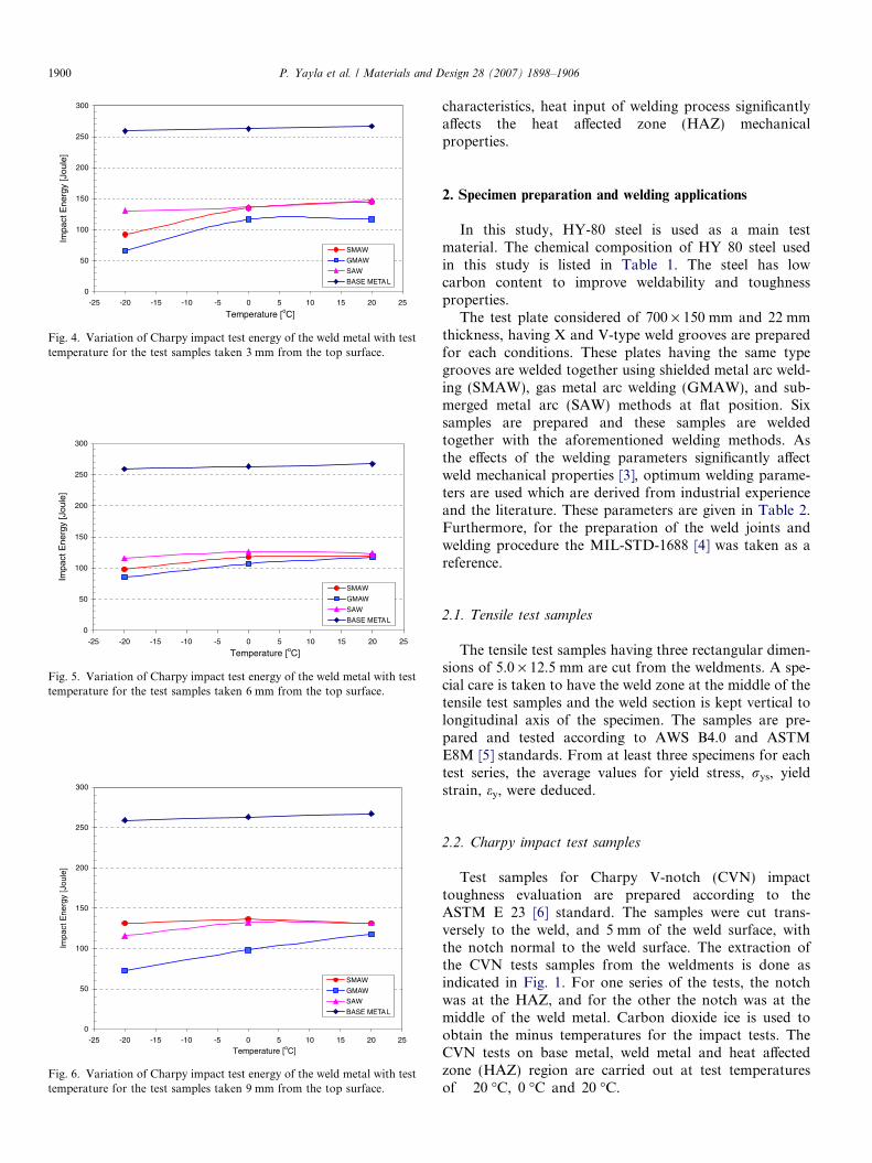
Fig. 4. Variation of Charpy impact test energy of the weld metal with testtemperature for the test samples taken 3 mm from the top surface.
0
50
100
150
200
250
300
-25 -20 -15 -10 -5 0 5 10 15 20 25
Temperature [oC]
]eluoJ[ ygrenE tcap
mI
SMAW
GMAW
SAW
BASE METAL
Fig. 5. Variation of Charpy impact test energy of the weld metal with testtemperature for the test samples taken 6 mm from the top surface.
0
50
100
150
200
250
300
-25 -20 -15 -10 -5 0 5 10 15 20 25
Temperature [oC]
]eluoJ[ yg renE tcap
mI
SMAW
GMAW
SAW
BASE METAL
Fig. 6. Variation of Charpy impact test energy of the weld metal with testtemperature for the test samples taken 9 mm from the top surface.
1900 P. Yayla et al. / Materials and Design 28 (2007) 1898–1906
characteristics, heat input of welding process significantlyaffects the heat affected zone (HAZ) mechanicalproperties.
2. Specimen preparation and welding applications
In this study, HY-80 steel is used as a main testmaterial. The chemical composition of HY 80 steel usedin this study is listed in Table 1. The steel has lowcarbon content to improve weldability and toughnessproperties.
The test plate considered of 700 · 150 mm and 22 mmthickness, having X and V-type weld grooves are preparedfor each conditions. These plates having the same typegrooves are welded together using shielded metal arc weld-ing (SMAW), gas metal arc welding (GMAW), and sub-merged metal arc (SAW) methods at flat position. Sixsamples are prepared and these samples are weldedtogether with the aforementioned welding methods. Asthe effects of the welding parameters significantly affectweld mechanical properties [3], optimum welding parame-ters are used which are derived from industrial experienceand the literature. These parameters are given in Table 2.Furthermore, for the preparation of the weld joints andwelding procedure the MIL-STD-1688 [4] was taken as areference.
2.1. Tensile test samples
The tensile test samples having three rectangular dimen-sions of 5.0 · 12.5 mm are cut from the weldments. A spe-cial care is taken to have the weld zone at the middle of thetensile test samples and the weld section is kept vertical tolongitudinal axis of the specimen. The samples are pre-pared and tested according to AWS B4.0 and ASTME8M [5] standards. From at least three specimens for eachtest series, the average values for yield stress, rys, yieldstrain, ey, were deduced.
2.2. Charpy impact test samples
Test samples for Charpy V-notch (CVN) impacttoughness evaluation are prepared according to theASTM E 23 [6] standard. The samples were cut trans-versely to the weld, and 5 mm of the weld surface, withthe notch normal to the weld surface. The extraction ofthe CVN tests samples from the weldments is done asindicated in Fig. 1. For one series of the tests, the notchwas at the HAZ, and for the other the notch was at themiddle of the weld metal. Carbon dioxide ice is used toobtain the minus temperatures for the impact tests. TheCVN tests on base metal, weld metal and heat affectedzone (HAZ) region are carried out at test temperaturesof �20 �C, 0 �C and 20 �C.

P. Yayla et al. / Materials and Design 28 (2007) 1898–1906 1901
2.3. Hardness measurements and microstructural
examination
For hardness measurements and microstructural exam-inations six samples of 10 · 20 · 80 mm dimensions aretaken from the weldments. The sample preparation andhardness measurements were done according to the ASTME92-82 [7] standard. The micro-hardness tests are con-
Fig. 7. Hardness profile across main material, HAZ an
ducted on cross-sections along a line 3 mm from the bothsurfaces of the plates at 0.5 mm intervals and at 9.81 Nweight. Zwick 3212001 hardness testing machine was used.The hardness measurements are done in order to measurethe degree of hardening along the base metal, HAZ andweld metal.
For the microstructural examination, the surfaces ofthe samples are polished until the scratches on the
d weld material regions for SMAW V test sample.
1902 P. Yayla et al. / Materials and Design 28 (2007) 1898–1906
cross-sections are eliminated well enough for the exami-nation. The polished surfaces are then etched by 5%nital. The micrographs of the etched surfaces are utilisedfor the study of HAZ and the heat-treated zones betweenthe weld passes.
3. Results and discussion
3.1. Tensile test
The tensile tests are carried out on the samples usingDARTEC Servo-hydraulic tensile testing machine. Thetests are performed according to ASTM E8M [5]standard at ambient temperature. The yield stress and yieldstrain values obtained from these tests are given in Fig. 2.One of the significant outcomes of these tests is that in
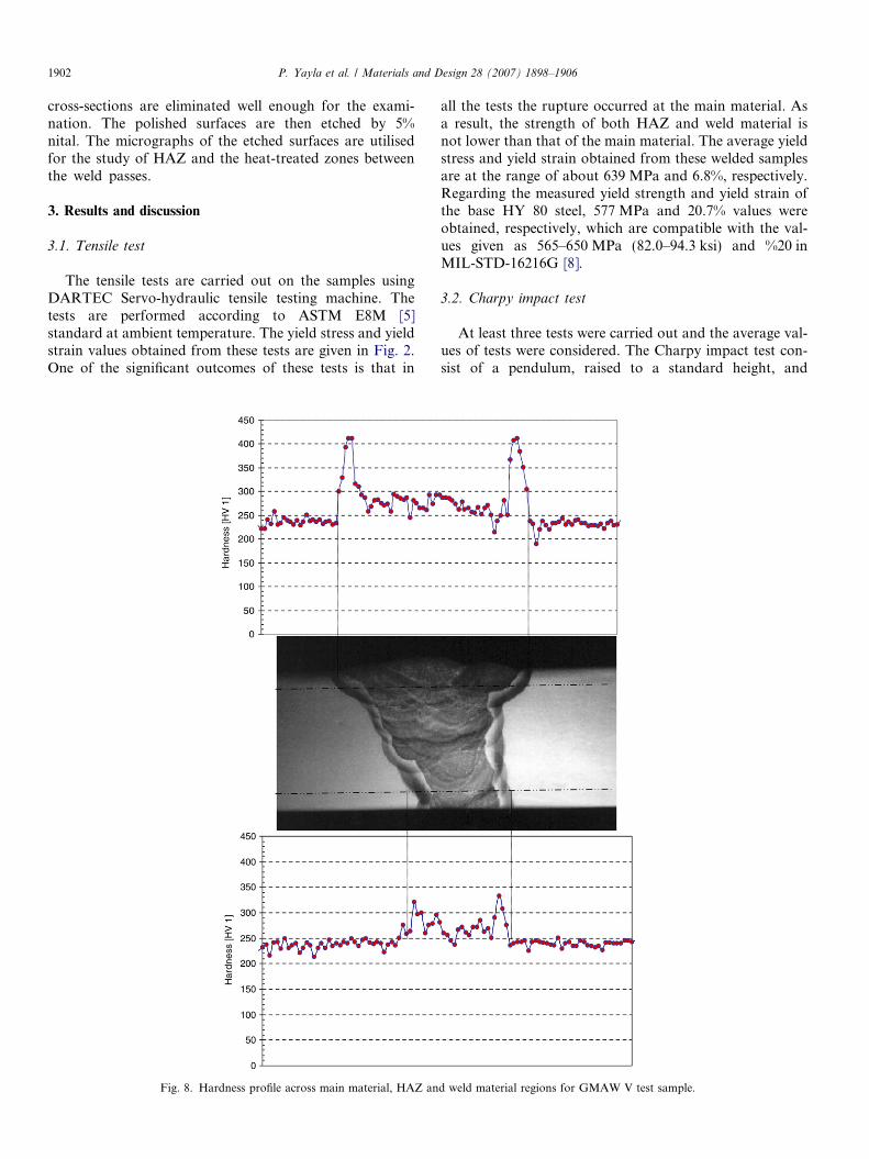
Fig. 8. Hardness profile across main material, HAZ an
all the tests the rupture occurred at the main material. Asa result, the strength of both HAZ and weld material isnot lower than that of the main material. The average yieldstress and yield strain obtained from these welded samplesare at the range of about 639 MPa and 6.8%, respectively.Regarding the measured yield strength and yield strain ofthe base HY 80 steel, 577 MPa and 20.7% values wereobtained, respectively, which are compatible with the val-ues given as 565–650 MPa (82.0–94.3 ksi) and %20 inMIL-STD-16216G [8].
3.2. Charpy impact test
At least three tests were carried out and the average val-ues of tests were considered. The Charpy impact test con-sist of a pendulum, raised to a standard height, and
d weld material regions for GMAW V test sample.

P. Yayla et al. / Materials and Design 28 (2007) 1898–1906 1903
released to strike a standard specimen. The energy requiredto fracture the specimen is a measure of energy lost by thependulum and named as Charpy impact energy. TheCharpy impact tests results obtained from the main mate-rial showed rather good repeatability.
In order to find out the Charpy impact energy of theHAZ, a number of tests samples for which the notch ison the HAZ, were carried out. These samples were taken5 mm from the top surface. These results are given inFig. 3, showing minimum impact energy for the GMAWand maximum for the SAW samples. These results arecomparable with the results of Rittler and Dixon [1]who studied the Impact energy variation with atemperature ranging between �50 and 0 �C for HY-80
Fig. 9. Hardness profile across main material, HAZ and
steel and observed almost a linearly increasing impactenergy variation with temperature between 55 J and125 J.
The variations of Charpy impact energy with the testtemperature for the samples extracted from the differentsections of the weld plate are given Figs. 4–6. For all thesetests, the Charpy notch is on the weld material. From theseresults it could be seen that the impact energy of weld metalvaries significantly with the weld method, giving the mini-mum Charpy impact energy for the whole temperaturerange at the GMAW test samples. This is attributed tothe elements reduction due to the oxidation effects of thegasses used in the GMAW welding. The highest Impactenergy is observed on the SAW weld sections, mainly for
weld material regions for SAW V-type test sample.
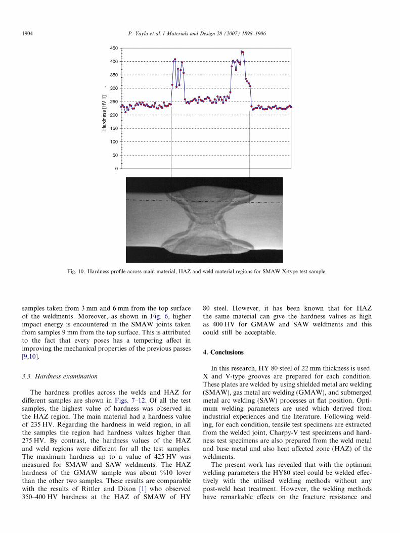
Fig. 10. Hardness profile across main material, HAZ and weld material regions for SMAW X-type test sample.
1904 P. Yayla et al. / Materials and Design 28 (2007) 1898–1906
samples taken from 3 mm and 6 mm from the top surfaceof the weldments. Moreover, as shown in Fig. 6, higherimpact energy is encountered in the SMAW joints takenfrom samples 9 mm from the top surface. This is attributedto the fact that every poses has a tempering affect inimproving the mechanical properties of the previous passes[9,10].
3.3. Hardness examination
The hardness profiles across the welds and HAZ fordifferent samples are shown in Figs. 7–12. Of all the testsamples, the highest value of hardness was observed inthe HAZ region. The main material had a hardness valueof 235 HV. Regarding the hardness in weld region, in allthe samples the region had hardness values higher than275 HV. By contrast, the hardness values of the HAZand weld regions were different for all the test samples.The maximum hardness up to a value of 425 HV wasmeasured for SMAW and SAW weldments. The HAZhardness of the GMAW sample was about %10 loverthan the other two samples. These results are comparablewith the results of Rittler and Dixon [1] who observed350–400 HV hardness at the HAZ of SMAW of HY
80 steel. However, it has been known that for HAZthe same material can give the hardness values as highas 400 HV for GMAW and SAW weldments and thiscould still be acceptable.
4. Conclusions
In this research, HY 80 steel of 22 mm thickness is used.X and V-type grooves are prepared for each condition.These plates are welded by using shielded metal arc welding(SMAW), gas metal arc welding (GMAW), and submergedmetal arc welding (SAW) processes at flat position. Opti-mum welding parameters are used which derived fromindustrial experiences and the literature. Following weld-ing, for each condition, tensile test specimens are extractedfrom the welded joint, Charpy-V test specimens and hard-ness test specimens are also prepared from the weld metaland base metal and also heat affected zone (HAZ) of theweldments.
The present work has revealed that with the optimumwelding parameters the HY80 steel could be welded effec-tively with the utilised welding methods without anypost-weld heat treatment. However, the welding methodshave remarkable effects on the fracture resistance and

Fig. 11. Hardness profile across main material, HAZ and weld material regions for GMAW X-type test sample.
P. Yayla et al. / Materials and Design 28 (2007) 1898–1906 1905
hardness of HAZ. In all the tensile tests carried out on thesamples extracted from the weldments, the ruptureoccurred at the main material. These critical results wererather important, since the traditional welding design prac-tices require the use of weld metal with higher yieldstrength than the base metal. The Charpy V-notch impacttest results have shown that, due to higher heat input, theSAW and the SMAW specimens have given better HAZtoughness than the GMAW process. Moreover, the hard-ness test results have shown that the SMAW and SAWwelding methods have given slightly higher hardness pro-file across welds metal and HAZ than the GMAW methodon the section 3 mm below the top surface of the weld-ments. Particularly, the HAZ is transition zone on thewelded joints and there is the risk of cracking along these
zones. The micro-hardness examination of the HAZregions in all weldments reviled that The HAZ readings(390–430 HV) were consistently higher than both the baseand weld metal readings. Although the hardness gradientvaries from one method to another, the maximum hard-ness reaches up to the maximum values of 425 HV at theHAZ in all the methods. Regarding the weld metal, thesimilar trend is observed in the hardness profile, that isthe hardness gradient varies from one method to another,the maximum hardness reaches up to the maximum valuesof 275 HV in the weld metal; which is well below than theHAZ hardness of 425 HV. In the roots of the weldments,the hardness distribution is lower than the upper surfaceof the weldments, which is mainly due to tempering effectsof the filler passes.

Fig. 12. Hardness profile across main material, HAZ and weld material regions for SAW X-type test sample.
1906 P. Yayla et al. / Materials and Design 28 (2007) 1898–1906
Acknowledgements
The authors thank Mr. O.N. Gungor and Mr. B. Cakicifor their contributions to the experiments. Also the contri-butions of Dr. N. Sari and Dr. A. Arici on the sample prep-aration and hardness measurements have also influencedthis work. The comments and critics of Dr. E. Engindenizfrom Drahtwarenfabrik Drahtzug Stein GmbH & Co. ofGermany is well appreciated.
References
[1] Ritter JC, Dixon BF. Improved properties in welded HY-80 steel forAustralian warship. Weld J 1987;66(3):33–44.
[2] Brosilow R. High-strength steels: a progress report. Weld Design MetFabr 1991;64(11):40–4.
[3] Sampath K, Civis DA, Kleinosky MJ. Effects of GMA weldingconditions on high strength steel weld metal properties for ship
structures. In: Proceedings of international symposium on low-carbonsteels for the 90’s. Warrendale (PA, USA): Minerals, Metals &Materials Soc (TMS); 18–21 October 1993. p. 539–48.
[4] MIL-STD-1688 fabrication, welding and inspection of HY 80/100submarine application.
[5] ASTM E8M-90a standard test methods for tension testing of metallicmaterials.
[6] ASTM E 23 standard test methods for notched bar impact testing ofmetallic materials.
[7] ASTM E92-82 standard test methods for vickers hardness of metallicmaterials.
[8] MIL-STD-16216G ship’s steel late, alloy, structural HY strength.[9] Cakici B. Investigation of mechanical properties of HY 80 steel
joints, welded by using arc welding methods, MSc Thesis.Kocaeli University, Graduate School of Natural and AppliedSciences; May 2002.
[10] Gungor ON. The effects of welding processes on the mechanicalproperties of the welded joint and HAZ for the quenched andtempered HY 80 high strength low alloy steel. MSc Thesis, KocaeliUniversity, Graduate School of Natural and Applied Sciences;October 1996.