Master-Slave Synchronous Control Method for Attenuating ...
15
Master-Slave Synchronous Control Method for Attenuating Dual Mode Electromechanical Transmission System Torsional Vibration Hui Liu Beijing Institute of Technology School of Mechanical Engineering Wei Zhang ( [email protected] ) Beijing Institute of Technology https://orcid.org/0000-0002-8305-1465 Xun Zhang Beijing Institute of Technology School of Mechatronical Engineering Zhen Wang Beijing Institute of Technology Pengfei Yan Beijing Institute of Technology Original Article Keywords: EMT, dynamic control, torsional vibration characteristics, active vibration control, master-slave control Posted Date: September 7th, 2021 DOI: https://doi.org/10.21203/rs.3.rs-850373/v1 License: This work is licensed under a Creative Commons Attribution 4.0 International License. Read Full License
Transcript of Master-Slave Synchronous Control Method for Attenuating ...

Master-Slave Synchronous Control Method forAttenuating Dual Mode ElectromechanicalTransmission System Torsional VibrationHui Liu
Beijing Institute of Technology School of Mechanical EngineeringWei Zhang ( [email protected] )
Beijing Institute of Technology https://orcid.org/0000-0002-8305-1465Xun Zhang
Beijing Institute of Technology School of Mechatronical EngineeringZhen Wang
Beijing Institute of TechnologyPengfei Yan
Beijing Institute of Technology
Original Article
Keywords: EMT, dynamic control, torsional vibration characteristics, active vibration control, master-slavecontrol
Posted Date: September 7th, 2021
DOI: https://doi.org/10.21203/rs.3.rs-850373/v1
License: This work is licensed under a Creative Commons Attribution 4.0 International License. Read Full License

Master-Slave Synchronous Control Method for Attenuating Dual Mode
Electromechanical Transmission System Torsional Vibration
Hui Liu, Wei Zhang*, Xun Zhang, Zhen Wang, Pengfei Yan
Abstract: The high-power electromechanical transmission(EMT) system is a typical dual-mode hybrid power transmission system. The
torque fluctuation of internal combustion engine causes serious shock and vibration problems of EMT. It is an important way to improve
the life and smoothness of EMT system by using high dynamic regulation of motor torque to suppress the torsional resonance amplitude.
Firstly, a lumped parameter rotational dynamic model of multi degree of freedom EMT system is established, and the inherent torsional
vibration characteristics and dynamic coupling mechanism of the system are analyzed. Secondly, based on the synchronous response of
the two motors in the open-loop state, a master-slave coupling EMT torsional active control strategy is proposed, and a speed feedback
proportional differential control algorithm is designed. Then, the influence of control parameters, including lever coefficient Kab,
proportional coefficient Kp and differential coefficient Kd, on the vibration characteristics of the system is analyzed. Finally, the calculation
is carried out in the frequency domain and compared with the optimal modal control algorithm. The results show that the lever coefficient
Kab and differential coefficient Kd of master-slave control can change the natural frequency of torsional vibration of the system, thus
significantly changing the vibration response of the system. Selecting appropriate control parameters can achieve peak clipping of EMT
torsional resonance amplitude, which is also of great significance to improve the NVH performance of the system.
Key words: EMT, dynamic control, torsional vibration characteristics, active vibration control, master-slave control
1 Introduction
Power split hybrid electric vehicle (HEV) is famous for its high efficiency and good dynamic performance, and has become a research hotspot in the field of hybrid electric vehicle in recent years. Fig.1 shows the structure diagram of a typical dual-mode power split hybrid electric vehicle. The core structure of the vehicle is the electro-mechanical transmission (EMT) which realizes the power split function. The external part of the transmission is connected with the internal combustion engine, axle and electric drive components. Three planetary gear sets (PG1, PG2, PG3), two motors (MGa, MGb), a clutch and a brake are integrated in the transmission box, in which (i= 1, 2, 3) is the grade of PG. The engine is meshed with planet carrier gear of PG1, and MGa is connected with ring gear of PG2 and inverter of battery. The sun gear and ring gear of PG1 are respectively connected to the bracket of the sun gear and PG2. The MGB is connected to the sun gear of the PG3. The output shaft is connected to the bracket of the PG3. By engaging or disengaging the brake and clutch in the transmission, two different hybrid drive modes can be switched. In the first working mode (EVT1 mode), the brake is engaged and the clutch is disengaged. In this mode, the output driving torque is relatively large, but the output speed is low, which can only cover the low speed range of the vehicle. When the vehicle accelerates to a higher speed, the clutch engagement and brake disengagement are switched to the second working mode (EVT1 mode) by operating the oil pressure valve. Compared with EVT 1 mode, in EVT2 mode, the vehicle can run at a higher speed. The maximum driving torque of EMT decreases with the increase of vehicle speed, and the maximum torque is limited by engine power. In the whole speed range, the transmission ratio from engine to wheel changes continuously according to the speed. The engine and vehicle motion are decoupled. By controlling the transmission ratio, the engine can always run in the working range with the highest fuel efficiency [1].
With the extensive and in-depth development of the research, the research direction gradually expands from structural design and energy management to dynamic coordination [2] and comfort improvement [3]. On the one hand, scholars study the transient process of mode switching, engine start and stop[4], focusing on reducing the impact force[5].On the one hand, the comprehensive analysis of the vibration characteristics of the system is devoted to improving the vibration response of the system[6].
* Corresponding author. E-mail: [email protected]
School of Mechanical Engineering, Beijing Institute of Technology, Beijing 100081, China

ring1
carrier1
sun1
ring2
carrier2
sun2
ring3
carrier3
sun3
Clutch
MGb
MGa
InverterBattery
Mechanical Path
Electrical Path
Engine
Damper
Wheel
PG1 PG2 PG3
Brake
Differential
EMT
Fig.1. Structure of dual mode power-split HEV
Reducing the low frequency torsional vibration of EMT system is an important way to improve HEV performance. Many studies have considered the active vibration control algorithm of parallel hybrid electric vehicle. Cauet[6] designed a linear variable parameter control strategy based on the internal model principle of multi sinusoidal continuous disturbance, which reduced the first and second order speed oscillation of engine torque ripple. Morandin[7] connected the motor to the engine as the control actuator, and proposed a control algorithm based on adaptive multi resonance controller.
However, the complex structure of the split transmission makes the dynamic analysis of the powertrain system difficult [8-
9]. There are more power sources and more complex power action and vibration transmission path in power split hybrid electric vehicle, which makes the realization of active vibration control extremely difficult. Kou [10] proposed a sliding mode control scheme to actively suppress the vibration of the power system. However, the torque relationship between motor and engine is established by assuming steady-state conditions. Ito [11] designed a feed-forward filter based on transfer function to compensate the torque ripple of the engine by compensating the torque of the motor. However, it is difficult to identify the transfer function of hybrid electric vehicle with power split. In addition, it is difficult to obtain the pulsating torque from the engine. Chen [12] considered the inertia effect of engine active damping vibration when starting and stopping, but ignored the inertia effect of planetary gear. Wang [14] proposed a mode conversion coordinated control algorithm for power split hybrid electric vehicle, which adopts model reference control to actively damp the vibration caused by acceleration without considering the torque fluctuation of engine. However, the algorithm does not consider the moment of inertia of planetary gear, and does not work for low-order torsional resonance.
Active damping method based on self-learning algorithm is a common method in active vibration control, which has good adaptive ability and is insensitive to the changes of model parameters. The application scenario of active damping method is that the damping force from the actuator acts on two degrees of freedom with the same motion relationship. However, in EMT system, two motors do not have the same motion relationship. Therefore, the active damping method cannot be simply used to suppress the torsional vibration of EMT system.
Yang [13] proposed a new efficient mode switching control method and an adaptive double loop control framework for mode switching control. FXLMS algorithm is the most famous algorithm in the active control of forced vibration, because it is reliable and easy to implement. FXLMS algorithm is widely used in active noise control [14], and it is also used in active vibration control of aircraft [16].
Aiming at the low-frequency torsional resonance of EMT, this paper focuses on the reduction of torsional vibration f peak value in the low-order resonance region. Based on the dual motor speed feedback, the master-slave motor control method is first proposed, the concept of leverage ratio is proposed, and the influence of leverage ratio on the resonance point of the system is analyzed. The active control algorithm of EMT torsional vibration based on PD algorithm is designed. The simulation results show that the control algorithm has significant suppression effect on two low order torsional resonance amplitudes of the system.
2 Torsional Vibration Characteristics of EMT System
2.1 Modeling of 6-DOF EMT system
This paper studies the low-frequency torsional vibration and its control, which is harmful to the system. The meshing of shaft and gear with high torsional stiffness is ignored. At the same time, it is assumed that the gear is a rigid body, clutch and brake do not have sliding friction. According to the bench test analysis of a heavy dual-mode power split hybrid electric vehicle, the concentrated parameter angular vibration model of the hybrid electric vehicle is established, as shown in Fig.2. The model abstracts 4 spring damping elements and 16 inertia disks with concentrated mass.
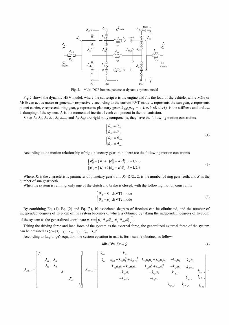
Fig. 2. Multi-DOF lumped parameter dynamic system model
Fig 2 shows the dynamic HEV model, where the subscript e is the engine and l is the load of the vehicle, while MGa or MGb can act as motor or generator respectively according to the current EVT mode. s represents the sun gear, c represents planet carrier, r represents ring gear, p represents planetary gears.𝑘𝑝𝑞(𝑝, 𝑞 = 𝑒, 𝑙, 𝑎, 𝑏, 𝑠𝑖, 𝑐𝑖, 𝑟𝑖) is the stiffness and and cpq is damping of the system. Jp is the moment of inertia of each component in the transmission.
Since Jr1-Jc2, Js1-Js2, Jr2-Jmga, and Js3-Jmgb are rigid body components, they have the following motion constraints
1 2
1 2
2
3
r c
s s
r ma
s mb
(1)
According to the motion relationship of rigid planetary gear train, there are the following motion constraints
1 , 1, 2,3
1 , 1, 2,3
si i ci i ri
si i ci i ri
K K i
K K i
& & & (2)
Where, Ki is the characteristic parameter of planetary gear train, Ki=Zr/Zs, Zr is the number of ring gear teeth, and Zs is the number of sun gear teeth.
When the system is running, only one of the clutch and brake is closed, with the following motion constraints
3
3
0 ,EVT1 mode
,EVT2 mode
r
c g
(3)
By combining Eq. (1), Eq. (2) and Eq. (3), 10 associated degrees of freedom can be eliminated, and the number of independent degrees of freedom of the system becomes 6, which is obtained by taking the independent degrees of freedom
of the system as the generalized coordinate x, e c1 ma g mb, , , , ,T
lx .
Taking the driving force and load force of the system as the external force, the generalized external force of the system can be obtained as [ ]0 0
T
e ma ma oQ T T T T .
According to Lagrange's equation, the system equation in matrix form can be obtained as follows
Jx Cx Kx Q && & (4)
mb
1 1e
2 2
1 1 3 1 2 3 4 1cc cr 1 3
2 2rc rr 1 2 3 4 2 4 2 4
_ __
1 2 _
3_3 b 4
ec ec
ec cg sb cg sb cgec sb
cg sb cg sb cg sbievt i evt i
cgl ig cg cg cg i
i c lsb isb
l
k kJ
k k a k a k a a k a a k aJ J k k a
J J k a a k a a k a k a k a k aJ K kJ k a k a k
kkk a k aJ
J
,
_
_ 3 _3
i
cgl i c l ic l
k k k
,
1 1
2 2
1 1 3 1 2 3 4 11 3
2 2
1 2 3 4 2 4 2 4
__
1 2 _
3 __3 b 4
ec ec
ec cg sb cg sb cgec sb
cg sb cg sb cg sb
evt icgl i
cg cg cg i
c l isb isb
c c
c c a c a c a a c a a c ac c a
c a a c a a c a c a c a c aC cc a c a c
ccc a c a
_ 3 _3
.
cgl i c l ic l
c c c
Where
2 2 2 2
cc c1 p1 1 1 r1 c2 p2 2 3 s1 s2
2
rc cr 1 2 r1 c2 p2 2 4 3 s1 s2
2 2 2
rr 4 s2 s2 2 r1 c2 p2 2 r2 ma
g g g g c3
2
mb mb s3 c3 mb mb s3
1 1 2 1 3 2
4 4
4
4
1,
c c
c
c
d
J J J R a J J J R a J J
J J a a J J J R a a J J
J a J J a J J J R J J
J J J J J
J J J J i J J J
a K a K a K
,
,
, 4 2 3
3 3
_1 _1 3 _1 _12
_ 2 3 _ 2 3 _ 2 _ 2 3
3 3
_1 _1 3 _1 _12
_ 2 3 _ 2 3 _ 2
1, , 1
, 0
0
0
, 0
d
c l c l
cg cg sb sb c l cgl
dd
cg cg c l sb sb c l cgl c l
c l c l
cg cg sb sb c l cgl
dd
cg cg c l sb sb c l c
a K i K
k kk k k k k k
ii
k k k k k k k k
c cc c c c c c
ii
c c c c c c c
, ,
, , ,
, , ,
, , _ 2 3gl c lc
.
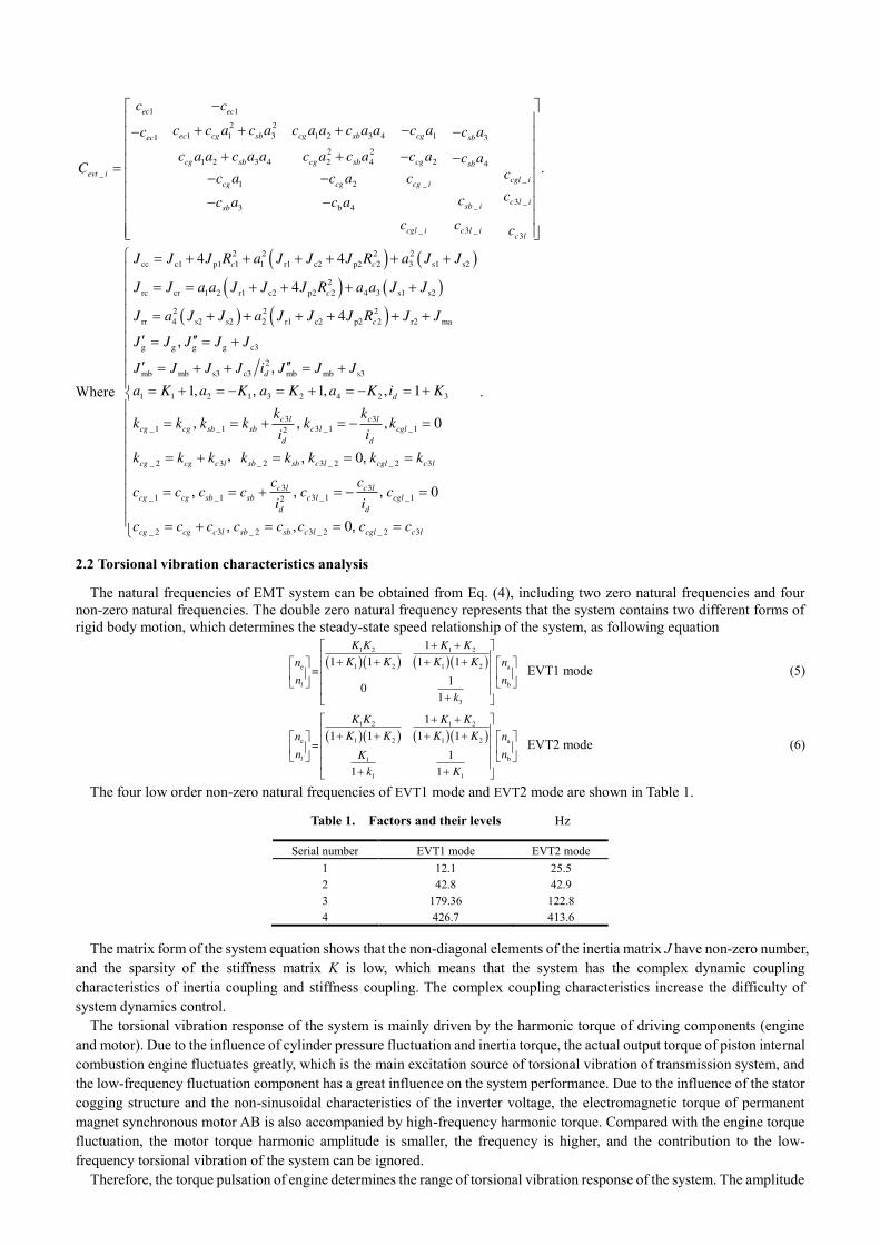
2.2 Torsional vibration characteristics analysis
The natural frequencies of EMT system can be obtained from Eq. (4), including two zero natural frequencies and four non-zero natural frequencies. The double zero natural frequency represents that the system contains two different forms of rigid body motion, which determines the steady-state speed relationship of the system, as following equation
1 2 1 2
1 2 1 2e a
b
3
1
1 1 1 1=
10
1
l
K K K K
K K K Kn n
n n
k
EVT1 mode (5)
1
1 1
1 2 1 2
1 2 1 2e a
b
1
1 1 1 1=
1
1 1
l
K K K K
K K K Kn n
n nK
k K
EVT2 mode (6)
The four low order non-zero natural frequencies of EVT1 mode and EVT2 mode are shown in Table 1.
Table 1. Factors and their levels Hz
Serial number EVT1 mode EVT2 mode
1 12.1 25.5
2 42.8 42.9
3 179.36 122.8
4 426.7 413.6
The matrix form of the system equation shows that the non-diagonal elements of the inertia matrix J have non-zero number, and the sparsity of the stiffness matrix K is low, which means that the system has the complex dynamic coupling characteristics of inertia coupling and stiffness coupling. The complex coupling characteristics increase the difficulty of system dynamics control.
The torsional vibration response of the system is mainly driven by the harmonic torque of driving components (engine and motor). Due to the influence of cylinder pressure fluctuation and inertia torque, the actual output torque of piston internal combustion engine fluctuates greatly, which is the main excitation source of torsional vibration of transmission system, and the low-frequency fluctuation component has a great influence on the system performance. Due to the influence of the stator cogging structure and the non-sinusoidal characteristics of the inverter voltage, the electromagnetic torque of permanent magnet synchronous motor AB is also accompanied by high-frequency harmonic torque. Compared with the engine torque fluctuation, the motor torque harmonic amplitude is smaller, the frequency is higher, and the contribution to the low-frequency torsional vibration of the system can be ignored.
Therefore, the torque pulsation of engine determines the range of torsional vibration response of the system. The amplitude

frequency characteristics of EMT speed fluctuation response excited by engine torque fluctuation are shown in Fig.3.
(a) EVT1 mode (b) EVT2 mode
Fig. 3. Speed response excited by engine torque
It can be seen from Fig.3 that the frequency response characteristics of the two modes are significantly different near the first and third natural frequencies. It can be seen from Table 1 that this is mainly caused by the obvious difference between the first and third natural frequencies.
In the process of EMT torsional vibration control, the motor, as the control actuator, outputs electromagnetic torque to suppress the vibration response of the system.In this paper, the improvement of the torsional vibration of the system when the fundamental torque of the motor is controlled is studied. Therefore, it is important to analyze the relationship between the torsional vibration state of the two motors and the torque pulsation of the engine under the condition of no torsional vibration control.
When there is no torsional vibration control, the relationship between motor state and engine torque is shown in Fig. 4 and Fig. 5
(a) Amplitude frequency characteristics in EVT1 mode (b) Phase frequency characteristics in EVT1 mode
Fig. 4. Frequency characteristics of motor vibration
(a) Amplitude frequency characteristics in EVT2 mode (b) Phase frequency characteristics in EVT2 mode
Fig. 5. Frequency characteristics of motor vibration
Fig.4 and Fig.5 show that in the low frequency range of engine torque ripple excitation (10Hz<100Hz), the amplitude of speed fluctuation of the two motors basically keeps a fixed proportion, and the phase difference is small, so they can be considered to have a considerable degree of synchronization.
3 Master-Slave Coupling Control
3.1 Control architecture
EMT control contains two control objectives. One is to adjust the torque value of each power component to achieve the target speed based on the rigid body motion state of the system to meet the power distribution and speed regulation
requirements of the system. The other is to apply additional motor dynamic torque based on the torsional vibration state to suppress the torsional resonance amplitude of the system excited by the torque ripple of the engine. Therefore, EMT system adopts cascade control framework, as shown in Fig.6. The outer loop is used for system speed regulation, which is considered as slow dynamic.
The inner loop is a high dynamic torsional vibration control, and the speed and torque of the outer loop are relatively stable in the torsional excitation time scale, which belongs to static control. The outer loop torque target is calculated by the vehicle controller.
This paper focuses on the inner loop EMT torsional vibration control.
Multi body HEV
model
Vehicle speed
Torque
addition
Dynamic torque controllor
State Output
Torsional vibration controlPowermanagement
Driver demand
SOC
Steady torque
HEV rigid
body model
HEV
Control
Unit
Dynamic
torque
Disturbance
Fig. 6. EMT control block diagram
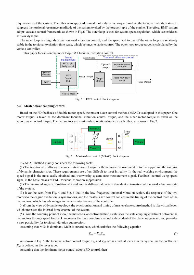
3.2 Master-slave coupling control
Based on the PD feedback of double motor speed, the master-slave control method (MSAC) is adopted in this paper. One motor torque is taken as the dominant torsional vibration control torque, and the other motor torque is taken as the subordinate control torque. The two motors are master-slave relationship with each other, as shown in Fig.7.
Engine C2
R2
S2
C1
R1
S1
C3
R3
S3
Motor A
Motor B
Brake
Vehicle
uclutch
Fig. 7. Master-slave control (MSAC) block diagram
The MSAC method mainly considers the following facts: (1) The traditional feedforward compensation control requires the accurate measurement of torque ripple and the analysis
of dynamic characteristics. These requirements are often difficult to meet in reality. In the real working environment, the speed signal is the most easily obtained and trustworthy system state measurement signal. Feedback control using speed signal is the basic means of EMT torsional vibration suppression.
(2) The measured signals of rotational speed and its differential contain abundant information of torsional vibration state of the system.
(3) It can be seen from Fig. 4 and Fig. 5 that in the low-frequency torsional vibration region, the response of the two motors to the engine excitation is synchronous, and the master-slave control can ensure the timing of the control force of the two motors, which has advantages in the anti-interference of the controller.
(4)From the view of dynamic topology, the synchronization and timing of master-slave control method is like virtual lever, which increases the internal force channel of the system.
(5) From the coupling point of view, the master-slave control method establishes the state coupling constraint between the two motors through speed feedback, increases the force coupling channel independent of the planetary gear set, and provides a new possibility for torsional vibration suppression.
Assuming that MGa is dominant, MGb is subordinate, which satisfies the following equation
mb ab maT K T (7)
As shown in Fig. 5, the torsional active control torque Tma and Tmb act as a virtual lever u in the system, so the coefficient Kab is defined as the lever ratio.
Assuming that the dominant motor control adopts PD control, then
ma mb ma mb ma
d
dp d
T K Kt
& & & &
(8)
If the dynamic excitation torque of the engine is w(t), the closed-loop equation of MSAC system is following
( )M F x C G x Kx Bw t && &
(9)
where
0 0 1
0 0 0
0
0
0
0 0 0
d d p p
ab d ab d ab p ab p
K K K KF G B
K K K K K K K K
O O
3.3 Response characteristics driven by control parameters
Let w(t)=0 in Eq.(8), the closed-loop dynamic characteristics of the MSAC can be obtained. The characteristics of the system are determined by the leverage ratio Kab, the proportional coefficient Kp and the differential coefficient Kd.
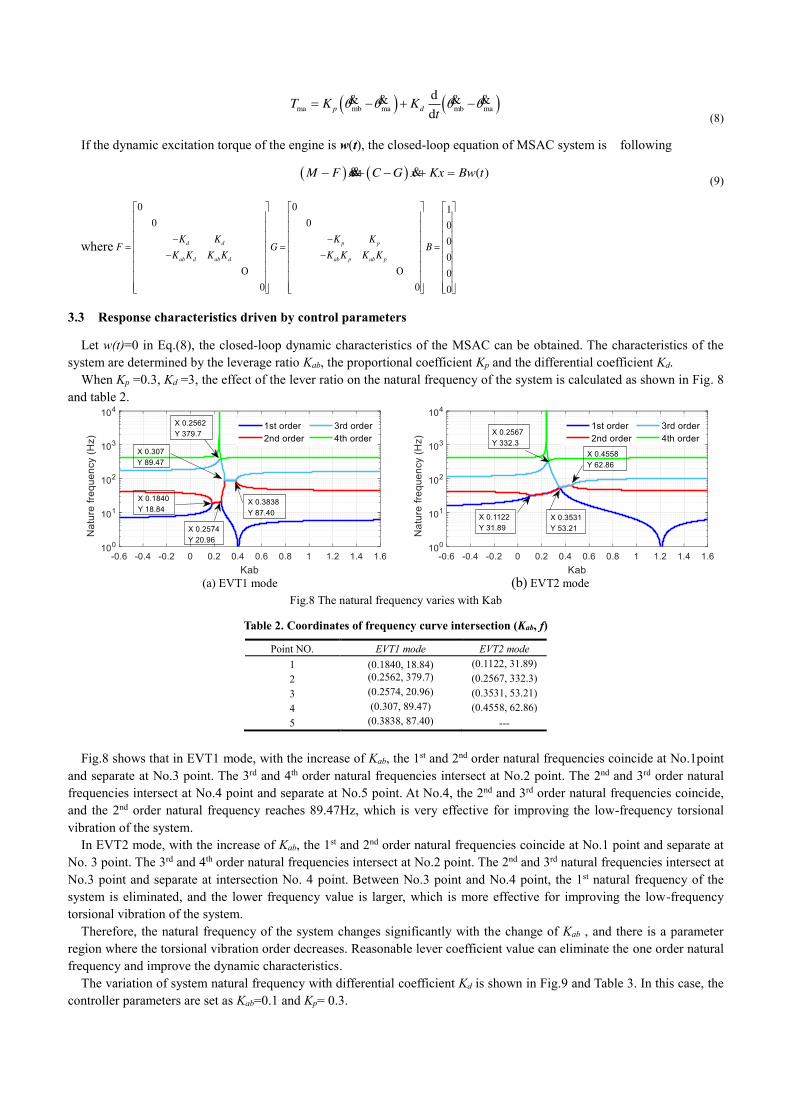
When Kp =0.3, Kd =3, the effect of the lever ratio on the natural frequency of the system is calculated as shown in Fig. 8 and table 2.
(a) EVT1 mode (b) EVT2 mode
Fig.8 The natural frequency varies with Kab
Table 2. Coordinates of frequency curve intersection (Kab, f)
Point NO. EVT1 mode EVT2 mode
1 (0.1840, 18.84) (0.1122, 31.89) 2 (0.2562, 379.7) (0.2567, 332.3) 3 (0.2574, 20.96) (0.3531, 53.21) 4 (0.307, 89.47) (0.4558, 62.86) 5 (0.3838, 87.40) ---
Fig.8 shows that in EVT1 mode, with the increase of Kab, the 1st and 2nd order natural frequencies coincide at No.1point and separate at No.3 point. The 3rd and 4th order natural frequencies intersect at No.2 point. The 2nd and 3rd order natural frequencies intersect at No.4 point and separate at No.5 point. At No.4, the 2nd and 3rd order natural frequencies coincide, and the 2nd order natural frequency reaches 89.47Hz, which is very effective for improving the low-frequency torsional vibration of the system.
In EVT2 mode, with the increase of Kab, the 1st and 2nd order natural frequencies coincide at No.1 point and separate at No. 3 point. The 3rd and 4th order natural frequencies intersect at No.2 point. The 2nd and 3rd natural frequencies intersect at No.3 point and separate at intersection No. 4 point. Between No.3 point and No.4 point, the 1st natural frequency of the system is eliminated, and the lower frequency value is larger, which is more effective for improving the low-frequency torsional vibration of the system.
Therefore, the natural frequency of the system changes significantly with the change of Kab , and there is a parameter region where the torsional vibration order decreases. Reasonable lever coefficient value can eliminate the one order natural frequency and improve the dynamic characteristics.
The variation of system natural frequency with differential coefficient Kd is shown in Fig.9 and Table 3. In this case, the controller parameters are set as Kab=0.1 and Kp= 0.3.
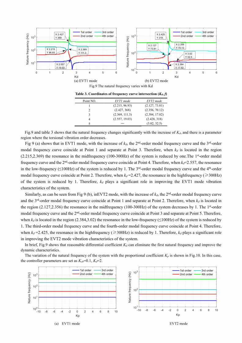
(a) EVT1 mode (b) EVT2 mode
Fig.9 The natural frequency varies with Kd
Table 3. Coordinates of frequency curve intersection (Kd, f)
Point NO. EVT1 mode EVT2 mode
1 (2.215, 96.93) (2.127, 73.81) 2 (2.427, 368) (2.356, 70.12) 3 (2.369, 111.3) (2.384, 17.02) 4 (2.557, 19.03) (2.428, 318) 5 --- (3.02, 32.5)
Fig.9 and table 3 shows that the natural frequency changes significantly with the increase of Kd, and there is a parameter region where the torsional vibration order decreases.
Fig 9 (a) shows that in EVT1 mode, with the increase of kd, the 2nd-order modal frequency curve and the 3rd-order modal frequency curve coincide at Point 1 and separate at Point 3. Therefore, when kd is located in the region (2.215,2.369) the resonance in the midfrequency (100-300Hz) of the system is reduced by one.The 1st-order modal frequency curve and the 2nd-order modal frequency curve coincide at Point 4. Therefore, when kd=2.557, the resonance in the low-frequency (≤100Hz) of the system is reduced by 1. The 3rd-order modal frequency curve and the 4th-order modal frequency curve coincide at Point 2. Therefore, when kd =2.427, the resonance in the highfrequency (≥300Hz) of the system is reduced by 1. Therefore, kd plays a significant role in improving the EVT1 mode vibration characteristics of the system.
Similarly, as can be seen from Fig 9 (b), inEVT2 mode, with the increase of kd, the 2nd-order modal frequency curve and the 3rd-order modal frequency curve coincide at Point 1 and separate at Point 2. Therefore, when kd is located in the region (2.127,2.356) the resonance in the midfrequency (100-300Hz) of the system decreases by 1. The 1st-order modal frequency curve and the 2nd-order modal frequency curve coincide at Point 3 and separate at Point 5. Therefore, when kd is located in the region (2.384,3.02) the resonance in the low-frequency (≤100Hz) of the system is reduced by 1. The third-order modal frequency curve and the fourth-order modal frequency curve coincide at Point 4. Therefore, when kd =2.425, the resonance in the highfrequency (≥300Hz) is reduced by 1. Therefore, kd plays a significant role in improving the EVT2 mode vibration characteristics of the system.
In brief, Fig.9 shows that reasonable differential coefficient Kd can eliminate the first natural frequency and improve the dynamic characteristics.
The variation of the natural frequency of the system with the proportional coefficient Kp is shown in Fig.10. In this case, the controller parameters are set as Kab=0.1, Kd=2.
(a) EVT1 mode EVT2 mode

Fig.10 The natural frequency varies with Kp
Fig.10 shows that the differential coefficient Kp does not change the value of the natural frequency of the system, but only affects the response amplitude of each natural frequency.
Comparing with figure 8, figure 9 and figure 10, it can be seen that the influence of master-slave coupling control method on the torsional vibration response of EMT system is determined by the leverage coefficient Kab, the proportional coefficient Kp and the differential coefficient Kd. The leverage coefficient Kab and the differential coefficient Kd can change the natural frequency of the torsional vibration.
Reasonable control parameters can achieve peak clipping of EMT torsional resonance amplitude. The optimal control parameters are Kp=0.3, Kd=3, Kab_evt1=0.268,Kab_evt2=0.31.
3.4 Independent mode space optimal control (IMSOC)
In order to highlight the peak clipping effect of MSAC, this paper also designs the optimal control method based on IMSOC[17] for simulation and comparison. The simulation results are compared.
Make a linear transformation to the Eq.(4).Let Q=0. The natural frequencies fi and mode shapes Φi are obtained.
Substituting the system mode matrix to transform e c1 ma g mb, , , , ,T
lx .
1
x q q x (10)
The following equation is obtained
q q Bu &&J K (11)
Further transformation
2 1
T T T
T
p p
T T
N
p
q q Bu
M q K q Bu
q q Bu Bu fM
&&
&&
&&
J K
(12)
Where Mp is the main mass matrix, Kp is the main stiffness matrix, T
N is the orthogonal normalization matrix,
=T
N NM I is the unit matrix,
1 i=diag( , , )T
N NK L is the spectral matrix, and Q is the 6-dimensional modal coordinate
vector and T
Nf Bu is the 6-dimensional modal control vector. ωi is the the i-th mode frequency.
The above equation is transformed into a decoupled state equation about the state vector z in the modal space
z Az BU & (13)
The matrix is partitioned according to the modal order, where 1 2 6 1 2 6[ , , , ] , block diag , , , ,T T T Tz z z z A A A A L L and
2
1 2 6
0[ , , , ] [ , ] , , [0, ]
1 0
T T T T T T Ti
i i i NiB B B B z q q A B B
&L , .
The output equation is as follows
6
1 2
1
z=i i
i
y C x C x C c z
& (14)
Where C1 and C2 are the output observation matrices of velocity and displacement respectively, 1 2[ , ]T
N NC C C
1 2 6, ( , , , )diag L , Ci is the observation matrix of the i-th mode. The i-th mode equation is
2 T
i i i N iq q Bu f && (15)
fi is the i-th mode control force. The i-th mode output is
1 0
0 1i i
qy Cz
q
& (16)
The linear quadratic performance equation is selected as

2 2 2 2
0
1
2i i i i i i
J q q r f dt
& (17)
where ri is the positive weighting coefficient. The i-th mode control quantity is
1 2
i i
i i
qu Gz g g
q
& (18)
When = , ,i i i
f t q q& , the mode control is the independent mode space control (IMSC). Select linear proportional control as follow
1 2= i i
i if g q g q& (19)
Take Eq.(19) into Eq. (17)
0
1
2
T T
i i i i i i iJ y Q y u R u dt
(20)
Where 2
1 0
0i i i
i
Q R r
, . According to the linear quadratic optimization theory, the control law of the infinite time
regulator is as follows
1 T
i i i i iu R B Pz
(21)
Where P is obtained from Riccati algebraic equation 1 0T T
i i i i i i i i iP A A P PB R B P Q
.
The control block diagram of IMSOC is shown in Fig.11.
Controlled Object
+
+1B
1
1g
1
2g
1
T
NM
1
T
NM
1q
1q
1f
u
x x
+6B
6
1g
6
2g
6
T
NM
6
T
NM
6q
6f
6q
Fig. 11. Control block diagram of IMSOC
4 Simulation Comparison of EMT Torsional Vibration Control
The simulation parameters of MSAC are set as Kp=0.3, Kd = 3, Kab_EVT1=0.267, Kab_EVT1=0.3. In contrast, the IMSOC is used to suppress the 1st order and 2nd order torsional vibration modes. The control objectives of master-slave motor active control (MSAC) and optimal mode space control (imsoc) are to reduce
the resonance peak at low frequency. The control objectives of Master-Slave motor Active Control (MSAC) and Independent Mode Space Optimal Control
(IMSOC) are to reduce the resonance peak in low frequency region. The amplitude frequency characteristics of vibration angular velocity response of each independent degree of freedom of EMT under engine pulsating torque excitation are shown in Fig. 12 to Fig. 17.

(a) EVT2 mode (b) EVT2 mode
Fig. 12. Amplitude frequency response characteristics of inertia disk speed ωe excited by engine torque Te
(a) EVT2 mode (b) EVT2 mode
Fig. 13. Amplitude frequency response characteristics of inertia disk speed ωc1 excited by engine torque Te
(a) EVT2 mode (b) EVT2 mode
Fig. 14. Amplitude frequency response characteristics of inertia disk speed ωma excited by engine torque Te
(a) EVT2 mode (b) EVT2 mode
Fig. 15. Amplitude frequency response characteristics of inertia disk speed ωg excited by engine torque Te
(a) EVT2 mode (b) EVT2 mode
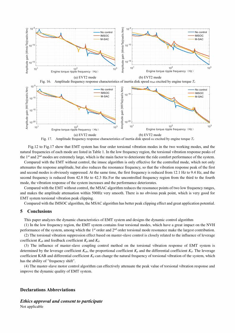
Fig. 16. Amplitude frequency response characteristics of inertia disk speed ωmb excited by engine torque Te
(a) EVT2 mode (b) EVT2 mode Fig. 17. Amplitude frequency response characteristics of inertia disk speed ωl excited by engine torque Te
Fig.12 to Fig.17 show that EMT system has four order torsional vibration modes in the two working modes, and the natural frequencies of each mode are listed in Table 1. In the low frequency region, the torsional vibration response peaks of the 1st and 2nd modes are extremely large, which is the main factor to deteriorate the ride comfort performance of the system.
Compared with the EMT without control, the imsoc algorithm is only effective for the controlled mode, which not only attenuates the response amplitude, but also reduces the resonance frequency, so that the vibration response peak of the first and second modes is obviously suppressed. At the same time, the first frequency is reduced from 12.1 Hz to 9.4 Hz, and the second frequency is reduced from 42.8 Hz to 42.3 Hz.For the uncontrolled frequency region from the third to the fourth mode, the vibration response of the system increases and the performance deteriorates.
Compared with the EMT without control, the MSAC algorithm reduces the resonance points of two low frequency ranges, and makes the amplitude attenuation within 500Hz very smooth. There is no obvious peak point, which is very good for EMT system torsional vibration peak clipping.
Compared with the IMSOC algorithm, the MSAC algorithm has better peak clipping effect and great application potential.
5 Conclusions
This paper analyzes the dynamic characteristics of EMT system and designs the dynamic control algorithm
(1) In the low frequency region, the EMT system contains four torsional modes, which have a great impact on the NVH
performance of the system, among which the 1st order and 2nd order torsional mode resonance make the largest contribution.
(2) The torsional vibration suppression effect based on master-slave control is closely related to the influence of leverage
coefficient Kab and feedback coefficient Kp and Kd.
(3) The influence of master-slave coupling control method on the torsional vibration response of EMT system is
determined by the leverage coefficient Kab, the proportional coefficient Kp and the differential coefficient Kd. The leverage
coefficient KAB and differential coefficient Kd can change the natural frequency of torsional vibration of the system, which
has the ability of "frequency shift".
(4) The master-slave motor control algorithm can effectively attenuate the peak value of torsional vibration response and
improve the dynamic quality of EMT system.
Declarations Abbreviations
Ethics approval and consent to participate Not applicable

Consent for publication Not applicable
Availability of data and materials Not applicable
Competing Interests The authors declare no competing financial interests.
Funding Supported by National Natural Science Foundation of China (Grant No. 5213000702)
Authors’ Contributions Hui Liu innovated the vibration control strategy; Wei Zhang wrote the manuscript; Xun Zhang was in charge of the whole
simulation test; Zhen Wang and Pengfei Yan assisted with data analyses. All authors read and approved the final manuscript.
Acknowledgements Not applicable.
Authors’ Information
Hui Liu, born in 1975, is currently a professor and a PhD candidate supervisor at National Key Laboratory of Vehicle
Transmission, School of Mechanical Engineering, Beijing Institute of Technology, China.
Wei Zhang, born in 1992, is currently a PhD candidate at National Key Laboratory of Vehicle Transmission, School of
Mechanical Engineering, Beijing Institute of Technology, China. He received his Master's degree from Yanshan University,
China, in 2018. His research interest includes vehicle dynamics control and transmission optimization. Tel: +86-
18801355502.
Xun Zhang, born in 1992, is currently a PhD candidate at National Key Laboratory of Vehicle Transmission, School of
Mechanical Engineering, Beijing Institute of Technology, China. He received his bachelor degree from Harbin Institute of
Technology, China, in 2013. His research interest includes vibration and control.
Zhen Wang, born in 1993, is currently a PhD candidate at National Key Laboratory of Vehicle Transmission, School of
Mechanical Engineering, Beijing Institute of Technology, China. He received his Master's degree from Beijing Institute of
Technology, Weihai, China, in 2018. His research interest includes gear design and transmission optimization.
Pengfei Yan, born in 1989, is currently a PhD candidate at National Key Laboratory of Vehicle Transmission, School of
Mechanical Engineering, Beijing Institute of Technology, China. He received his Master's degree from North University of
China, in 2017.
References
[1] Xiang C, Ding F, Wang W, et al. Energy management of a dual-mode power-split hybrid electric vehicle based on velocity prediction and nonlinear model predictive control [J]. Applied Energy, 2017, 189(MAR.1): 640–653.
[2] Yang C, You S, Wang W, et al. A stochastic predictive energy management strategy for plug-in hybrid electric vehicles based on fast rolling optimization. [J]. IEEE Transactions on Industrial Electronics, 2020, 67(11):9659 - 9670.
[3] Wang W , Xiang C , Liu H , et al. A model-predictive-control-based power management strategy for a power-split electromechanical transmission[J]. Proceedings of the Institution of Mechanical Engineers Part D Journal of Automobile Engineering, 2016,230(14):1987-2001.
[4] Wang C, Yang M, Zheng W, et al. Vibration suppression with shaft torque limitation using explicit MPC-PI switching control in elastic drive systems[J]. IEEE Transactions on Industrial Electronics, 2015, 62(11): 6855–6867.
[5] Crolla D A, Cao D. The impact of hybrid and electric powertrains on vehicle dynamics, control systems and energy regeneration[J]. Vehicle System Dynamics, 2012,50(1):95–109
[6] Cauet S, Coirault P, Njeh M. Diesel engine torque ripple reduction through LPV control in hybrid electric vehicle powertrain: Experimental results[J]. Control Engineering Practice, 2013, 21(12), 1830–1840.
[7] M Morandin, S Bolognani, A Pevere, et al. Active Torque Ripple Damping in Direct Drive Range Extender Applications: A Comparison and an Original Proposal[C]. 2015 IEEE Vehicle Power and Propulsion Conference (VPPC), 2015, pp. 1-6, doi: 10.1109/VPPC.2015.7352891.
[8] Chen X, Hu J, Peng Z, et al. Bifurcation and chaos analysis of torsional vibration in a PMSM-based driven system considering electromechanically coupled effect[J]. Nonlinear Dynamics, 2017, 88(1), 277–292.
[9] Xiang C, Liu F, Liu H, et al. Nonlinear dynamic behaviors of permanent magnet synchronous motors in electric vehicles caused by unbalanced

magnetic pull[J]. Journal of Sound and Vibration, 2016, 371, 277–294. [10] You S K , Weslati F . Development of a hybrid powertrain active damping control system via sliding mode control scheme [C]. SAE Technical Paper
2013-01-0486, 2013. https://doi.org/10.4271/2013-01-0486
[11] Ito Y, Tomura S, Sasaki S . Development of Vibration Reduction Motor Control for Hybrid Vehicles[C]. IECON 2007 - 33rd Annual Conference of the IEEE Industrial Electronics Society, 2007, pp. 516-521, doi: 10.1109/IECON.2007.4460237.
[12] Chen J S , Hwang H Y. Engine automatic start–stop dynamic analysis and vibration reduction for a two-mode hybrid vehicle[J]. Proceedings of the Institution of Mechanical Engineers Part D Journal of Automobile Engineering,2013,227(9), 1303–1312.
[13] R Madoński, Stankovi M R , Shao S S , et al. Active disturbance rejection control of torsional plant with unknown frequency harmonic disturbance[J]. Control Engineering Practice, 100, Article 104413.
[14] Chen W, Zhao Z, Tong Z, et al. Mode transition coordinated control for a compound power-split hybrid car[J]. Mechanical Systems and Signal Processing, 2017, 87(PT.A):192-205.
[15] Mondal K, Das S , Abu A B H, et al. All-pass filtered x least mean square algorithm for narrowband active noise control[J]. Applied Acoustics, 142, 1–10.
[16] Niu W, Zou C, Li B, et al. Adaptive vibration suppression of time-varying structures with enhanced FxLMS algorithm[J]. Mechanical Systems and Signal Processing, 2019, 118, 93–107.
[17] Lindberg R E, Longman R W. On the Number and Placement of Actuators for Independent Modal Space Control [J]. Journal of Guidance Control & Dynamics, 2012, 7(2):215-221.