Mass Production Electroforming Of A Three Dimensional ...infohouse.p2ric.org/ref/31/30484.pdf ·...
31
MASS PRODUCTION ELECTROFORMING OF A THREE DIMENSIONAL COMPONENT CBarnes and T.J.Crichton The Gillette Company, UK Research and Development Laboratory, Reading, England. Abstract The development of a process for the mass production of a small three dimensional component is described. The process involved electroforming *nickel of near uniform thickness around a disposable precision moulded polystyrene master. The master was metallised with silver, using plasma etching to prepare the plastic surface and "silver spraying" to deposit a thin metallic coating. A computer modelling programme was used to design a jig that minimised wall thickness variation. A novel feature of the jig was it being construct e d principally from polyethylene t e re p h t h a1 a t e. Addition a1 con t r o 1 measures undertaken to minimise wall thickness variation are also described. -1- 94
Transcript of Mass Production Electroforming Of A Three Dimensional ...infohouse.p2ric.org/ref/31/30484.pdf ·...
+ MASS PRODUCTION ELECTROFORMING OF A THREE DIMENSIONAL
COMPONENT
C B a r n e s a n d T.J.Crichton
The Gillette Company, UK Research and Development Laboratory, Reading, England.
A b s t r a c t
T h e d e v e l o p m e n t of a p r o c e s s f o r t h e mass p r o d u c t i o n of a sma l l t h r e e dimensional component is descr ibed. T h e process involved e lec t roforming
* n i c k e l of n e a r u n i f o r m t h i c k n e s s a r o u n d a d isposable prec is ion moulded polystyrene master. The master was metallised with silver, using plasma etching to p repa re the plast ic sur face and "silver spraying" to deposi t a thin metallic coat ing. A c o m p u t e r mode l l ing p r o g r a m m e was used t o des ign a j ig t h a t minimised wal l th ickness var ia t ion . A novel f ea tu re of the j ig was i t being construct e d principally f r o m polyethylene t e re p h t h a1 a t e. Addit ion a1 con t r o 1 measures undertaken t o minimise wall thickness variation a re also described.
-1-
943

The Proceedings of the 79th AESF Annual Technical Conference SUC;L/FI'N@ *=z S M N
Juri- ZZ-ZS, ISSZ Atlanta, Georgia
1 I
The American Electroplaters and Surface Finishers Society, Inc. (AESF) is an international, individual- membership, professional, technical and educational society for the advancement of electroplating and surface finishing. AESF fosters this advancement through a broad research program and comprehensive educational programs, which benefit its members and all persons involved in this widely diversified industry, as well as govemment agencies and the general public. AESF dissemi- nates technical and practical information through its monthly joumal, Plating and Surface Finishing, and through reports and other publications, meetings, symposia and conferences. Membership in AESF is open to all surface finishing professionals as well as to those who provide services, supplies, equipment, and support to the industry.
According to the guidelines established by AESF's Meetings and Symposia Committee, all authors of papers to be presented at SUWFIN@ have been requested to avoid commercialism of any kind, which includes references to company names (except in the title page of the paper), proprietary processes or equipment.
Statements of fact or opinion in these papers are those of the contributors, and the AESF assumes no responsibility for them.
All acknowledgments and references in the papers are the responsibility of the authors.
Published by the American Electroplaters and Surface Finishers Society, Inc. 12644 Research Parkway Orlando, FL 32826-3298 Telephone: 407/281W1 Fax: 407E81-6446
Copyright 1992 by American Electroplaters and Surface Finishers Society, Inc. All rights ' reserved. Printed in the United Statas of
,12644 Research means, electronic. mechanical, photocopying, recording, or otherwise without the prior writtenparrmssion of AFSF Parkway, Orlando, FL 32826-3298.
' whole or part, in any form or by- r$, herica,This publication may not be reoroduced, stored in a retrieval s v s m . .
Printed by AESF Press
SUWIN'is a registered trademark of the American Electroplaters and Surface Finishers Society, Inc.

In t roduc t ion
A new product under development by Gillette required a thin wall metal cylinder with a taper at one end a s one of its components. The basic requirements were tha t the component, which is only about 20" long and 4mm wide, should be of bright metal, only 0.1 to 0.15 mm thick, yet rigid and not easily damaged. To fac i l i t a te high speed au tomated assembly of the new product, the internal and external dimensions of this cylindrical component had to be tightly controlled with minimal batch t o batch variation. Approximately 35 million components per year were specif ied, thus a fully au tomated manufactur ing opera t ion was necessary to keep component costs low.
A f t e r cons ide ra t ion a n d feasibi l i ty tr ials of var ious possible manufacturing techniques, electroforming was selected for fur ther development. T h e process adopted consisted of:
i) precision moulding a disposable plastic master ii) electroforming nickel around the master iii) removing the plastic master to leave a f ree standing nickel shell.
Electroforming was selected because, in addition to producing components with al l the appropriate attr ibutes, product assembly problems could be eliminated by the incorporation of addi t ional design f ea tu res not easily real ised with o ther manufactur ing techniques. The disadvantages with electroforming a re that the process is relatively slow, i t is difficult to control the wall thickness of a three d imens iona l shape and the mass production of three dimensional electroforms has only rarely been at tempted. However, o n this occasion the advantages of electroforming outweighed the disadvantages.
This paper describes some of the main features of the development programme carried out by Gil le t te in the U.K. Research and Development Laboratory. A nove l des ign of j i g was deve loped to achieve t h e necessary con t ro l of wall thickness and the programme culminated in a pre production trial which proved the effectiveness of the process and in particular, the jig design.
The Plas t i c M a s t e r Mould ing
T h e master moulding controls the internal dimension of the electroform. The tolerance on the internal d iameter of the electroform was k0.02 mm, thus the d imens ions of the moulding must be strictly controlled. The component was a com licated shape which must be reproduced in the moulding cavity. The high
d imens ions must b e cons is ten t . Po l i sh ing a f t e r s p a r k e r o s i o n machin ing inevitably resul ted in a n unacceptable dimensional variation between cavities. Electroforming hard nickel a round a polished meta l male mandrel produced cavities of consistent dimensions and with the required surface finish without any additional polishing operations.
Usual ly f o r p la t ing on p las t ics ope ra t ions , ABS is t he p r e f e r r e d moulding m a t e r i a l . H o w e v e r , c o m p l e t e r e m o v a l of t h e m a s t e r mou ld ing f rom the electroform was essential and the slight draft along the length of the component p reven ted mechan ica l s e p a r a t i o n ; hence d isso lu t ion of t he mas ter was the
p r o B uct volumes specified required a multi cavity moulding tool, thus inter cavity
-2-
944

preferred method. ABS is not easily dissolved by common inexpensive soivents and thus could not be used.
The material selected for moulding was Medium Impact Polystyrene containing approximately 5 % of butadiene; pure polystyrene is too brittle and cracked in later assembly operations. The plastic selected is a standard low cost mater ia l widely used f o r precision injection moulding applications. This plastic is very soluble in a wide range of organic solvents including chlorinated hydrocarbons and complete removal of the masters was achieved using these solvents.
Barrel electroforming had been considered as a possible method of manufacture, but in addition to the problems associated with the barrel plating of plastics, it is also more difficult to achieve the specified uniform wall thickness.
T h e plastic masters were t ransported through the electroforming process on a ca r r i e r known as a l adde r . Th i s l a d d e r was des igned with angled s ides t o fac i l i t a te ease of e ject ion f r o m the inject ion moulding tool. T h e use of the ladder made i t easier to precisely position the masters in the electroforming jig and the angled sides of the ladder were used to make electrical contact against the conductor strip of this jig. T h e ladders were also moulded in polystyrene and the masters were permanent ly a t tached to the ladders by ultrasonic welding. Each ladder carried 15 masters a t an 8 mm pitching; the configuration is shown in Figure 1. T h e maximum d iame te r of the master was 5.18 mm, thus at their closest point the masters were only 2.82 mm apart .
Meta l l i s ing of t h e M a s t e d L a d d e r Assembly
Although polystyrene can be metallised with copper o r nickel by conventional electroless plating techniques, difficult ies were encountered in applying this technology to o u r process. T h e e lec t roform had t o b e void f ree , therefore a cont inuous s t r ike meta l layer was essent ia l and any incompletely metall ised masters would d is tor t the electroformed wall thickness dis t r ibut ion on t h e i r neighbours, thus multiplying the number of rejects. With electroless plating, a small percentage of rejects was always obta ined , discontinuous metall isation usually occurred around the ultrasonic weld at the master ladder interface. This failure level was unacceptable and the electroless processes were not used.
"Silver spraying" is the chemical reduction process formerly used to coat glass with silver to manufacture mirrors and has also been widely used in the record industry for metallising the cut wax master discs. This is a simple process, using low cost equipment and can be used to deposi t silver on plastics. This silver coat ing, a l though only 0.1 to 0.2 pm th ick , i s c o n t i n u o u s a n d is i d e a l f o r s u b s e q u e n t e l e c t r o f o r m i n g . T h e p r o c e s s a l so has a very low fa i lu re r a t e particularly if the plast ic par t s to b e metal l ised a r e kept c lean and f r e e f rom contamination.
To achieve good adhesion of the metal coating to the plastic, the surface of the plastic master must be clean and is etched prior to metal deposition. Chemical etching using chromic acid based solutions was originally used to etch the plastic but th i s process has many d isadvantages . T h e ch romic acid so lu t ions a r e extremely toxic and was te d isposa l is t h e r e f o r e very expensive. Due to the increased concerns and legislation being introduced in both the United States

and Europe relat ing to environmental issues involving the use of hexavalent c h r o m i u m i t was c o n c l u d e d t h a t t h e e l i m i n a t i o n of sys tems us ing t h e s e compounds would be most beneficial.
Plasma t rea tment of a polymer surface can provide a controlled change to the polymer’s surface energy, which, if increased by introducing polar funct ional groups, can result in a greater chemical reactivity and compatibility with paints, inks, adhesives and metal films. Enhanced surface energy is easily recognisable by increased wa te r wettabil i ty of the polymer surface and the consequent ia l decrease in contact angle between the water and the polymer surface. In general, gases that contain oxygen a re more effective at increasing the surface energy of a polymer. Consequently one of the most common gases used in plasma activation is oxygen. The oxygen also readily combines with degraded organic compounds to produce innocuous species such a s C 0 2 and H20, so no t r ea tmen t of t h e vented gas stream is necessary. The process also offers the advantage that i t does n o t g e n e r a t e a n y o t h e r b y - p r o d u c t s t h a t w o u l d b e c o n s i d e r e d t o b e e nv i r o n me n t a 1 ly hazardous.
P l a s m a e t c h i n g in low p r e s s u r e a i r o r oxygen p roved a o o d m e t h o d of pretreating polystyrene to obtain good silver adhesion. T h e ef B ectiveness of the p l a s m a t r e a t m e n t i s immedia te ly obvious by t h e f a c t t ha t the polystyrene becomes hydrophilic. A disadvantage is t ha t t he plasma t rea tment does no t clean the plastic surface. Surface contamination of the plastic by fingerprints, f o r i n s t ance , c a n p r e v e n t g o o d s i lve r d e p o s i t i o n , r e s u l t i n g in a void i n t h e e l e c t r o f o r m . T h u s t h e c o m p o n e n t s h a d t o b e k e p t c l e a n a n d f r e e f r o m contamination t o avoid the need to introduce an additional cleaning and drying operation.
T h e adhes ion of t h e si lver coat ing t o the polystyrene was checked by a tape adhes ion tes t a n d was always exce l len t if c l e a n c o m p o n e n t s w e r e p l a s m a activated. Plasma act ivat ion gave f a r superior adhesion to that achieved with chromic acid etching.
The plasma etching system used was a fully automatic microprocessor controlled unit and could accommodate up to 120 ladders (Le. 1800 masters). The unit had a 550 watt, 13.56 Mhz RF generator . Plasma t r ea tmen t t ime was 100 seconds using oxygen a t a pressure of 250mT as the t reatment gas; air was also effective with a longer t reatment time. Tota l cycle time including pump down and venting was 9 minutes.
Af te r plasma t rea tment , t h e surface of the polystyrene remained active for a considerable period if stored in clean dry conditions. Satisfactory adhesion of s i lver t o po lys ty rene has b e e n o b t a i n e d 24 hours a f t e r p lasma ac t iva t ion , although if the product is carefully stored, the t reated surface remains active for a period of weeks.
T h e silver coa t ing of the plast ic masters was carr ied out using conventional spraying techniques and involved the following sequence of operations:-
-4-
946
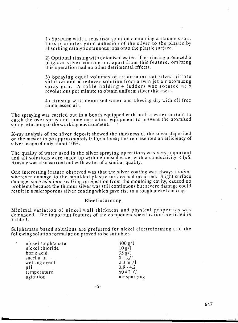
1) Spraying with a sensitiser solution containing a stannous salt. T h i s p r o m o t e s g o o d adhes ion of t h e si lver to the plast ic by absorbing catalytic stannous ions onto the plastic surface.
2) Optional rinsing with deionised water. This rinsing produced a b r igh te r s i lver coa t ing bu t a p a r t f rom this f e a t u r e , omi t t ing this operat ion had no other detrimental effects.
3) Spraying e q u a l vo lumes of a n a m m o n i a c a l s i lver n i t r a t e so lu t ion a n d a r e d u c e r so lu t ion from a twin j e t a i r atomising s p r a y g u n . A t a b l e h o l d i n g 4 l a d d e r s w a s r o t a t e d a t 6 revolutions pe r minute to obtain uniform silver thickness.
4) Rins ing w i t h deionised water and blowing dry with oil f r e e compressed air.
The spraying was carried out in a booth equipped with both a water curtain to catch the over spray a n d f u m e extract ion equipment t o prevent the atomised spray returning to the working environment.
X-ray analysis of the silver deposit showed the thickness of the silver deposited on the master to be approximately 0.15pm thick; this represented an efficiency of silver usage of only about 10%.
The quality of water used in the silver spraying operat ions was very important and all solutions were made u p with deionised water with a conductivity < ZpS. Rinsing was also carried out with water of a similar quality.
One interesting fea ture observed was that the silver coating was always thinner wherever damage to t h e m o u l d e d plastic surface had occurred. Slight surface damage, such as minor scuffing on ejection from the moulding cavity, caused no problems because the thinner silver was still continuous but severe damage could result in a microporous silver coating which gave rise to a rough nickel coating.
E lec t ro fo rming
Min ima l v a r i a t i o n of n i c k e l wa l l t h i ckness a n d physical p r o p e r t i e s was demanded. The important fea tures of the component specification a re listed in Table 1.
Sulphamate based solut ions a r e prefer red fo r nickel e lectroforming and the following solution formulation proved to be suitable:-
nickel sulphamate nickel chloride boric acid saccharin wetting agent PH temperature agitation
400 g/1 10 g/l 35 g/1 0.1 g/l 0.3 ml/l
6 0 k 2 C air sparging
3.9 - 4,2
-5 -
I
947

The deposit propert ies obtained from this solution were:-
hardness 320 - 370 HV internal stress ductility (elongation) 9 - 15%
7 - 10 kp.s.i. (compressive)
T h e s i lver coa t ing was very thin, only 0.1 t o 0.2 p m thick, and was therefore extremely fragile and unable to carry high electric currents. Normal methods for preparing metals for electroplating were inappropriate since these would detach the silver f rom t h e plastic. To avoid contaminat ion of the silver surface, the m e t a l l i s e d m a s t e r s w e r e n o t h a n d l e d a n d w e r e s t o r e d in a c l e a n , dry environment for a s short as time a s possible. Thus,the masters were maintained i n a suf f ic ien t ly c l e a n cond i t ion to al low a very mild activation procedure. Immersion of the par ts in a dilute surfactant solut ion was adequa te ; a f te r this t r e a t m e n t t h e s i l v e r s u r f a c e w a s h y d r o p h i l i c . To avo id poss ib l e c ross contamination of the nickel e lectroforming solut ion, the same surfactant was used in both solutions.
The silvered masters were immersed in this surfactant solution for 1 minute and af ter the activation treatment, the parts were rinsed by immersion in deionised water and then transferred to the electroforming solution. To avoid corrosion of the silver by the nickel sulphamate solution, live entry of the jig was necessary so tha t nickel was deposited onto the silver immediately it came into contact with the electroforming solution.
The nickel electroformin%process was carried out at an average current density of approximately 6 A / d m . A t this current density, nickel is deposited at about 1.2 pmlmin , giving a n electroforming time of less than 90 minutes to obtain the requi red thickness of nickel. Opera t ing a t this current density also deposited n i cke l w i t h t h e r e q u i r e d phys ica l p r o p e r t i y . T h e s o l u t i p n c a n o p e r a t e satisfactorily at current densities up t o 12 A/dm . Thus 6A/dm- average current density gave a d e q u a t e l a t i t ude f o r high c u r r e n t dens i ty e f fec ts o n complex s h a p e d pa r t s . T h e s i lver coa t ing was no t t h i c 5 e n o u g h to carry the current loading required f o r a current density of 6 A / d m and the electroforming was s tar ted at o n e eighth of final operating current and slowly stepped up to the final current a s the nickel thickness increased.
Control of E l e c t r o f o r m Wall Thickness
The high production volumes specified required a large electroforming jig. A jig accommodating 20 ladders (300 masters) was considered optimum. The ladders were arranged in 2 parallel linear arrays. Electroforming with a single anode on e a c h s i d e of a conven t iona l unsc reened j ig p roduced e l ec t ro fo rms with an unacceptably large variation of wall thickness. The nickel thickness where the components came closest together was very low, whereas the thickness on those areas facing the anodes was high. The ratio of minimum to maximum thickness at sections B and C of Figure 2 was typically less than 0.3 and at section D, where the components a r e closest together, the ratio is even smaller. There was also a
-6-
948

thickness variation along the length of the component with excessive deposition on the tapered end. There was also a thickness variatior? along the length of the jig with the thickest components being at the ends of the jig. This variation was due to end effects, and compounded the circumferential variation, resulting in the electroforms a t the end of the j ig being greatly in excess of the thickness specification.
The nickel wall thickness can be made more uniform by attaching side screens to the jig to redistribute the electric field around the masters, The novel jig design was accomplished using a computer modelling programme to def ine j ig/screen s h a p e a n d f ina l f i n e tun ing by experimentat ion-The j ig computer modelling facility eliminated a lot of trial and er ror electroforming experiments.
T h e Sheff ie ld E lec t rodepos i t i on M o d e l l i n g Sys tem was deve loped a t t h e University of Sheffield, EngIand, and is a generalised programme for predicting c u r r e n t dens i t i e s a r o u n d c a t h o d e boundar i e s . T h e sys tem was or ig ina l ly developed for designing chromium electroplating jigs but is equally suitable for nickel electroforming. T h e programme was used t o predict pr imary cu r ren t dis t r ibut ions but a recent extension to the sof tware allows secondary current distribution to be predicted. T h e programme can handle up t o 240 boundary elements which is insufficient for the whole jig hence a section consisting of only a few masters was modelled.
To reduce nickel build u p a t t he tapered e n d of t h e mas ter , t h e 2 arrays of ladders were a r ranged with the tapered ends of the masters directly opposite e a c h o the r . T h e c o m p u t e r mode l l ing p r o g r a m m e p r e d i c t e d the o p t i m u m separation of the arrays and this proved to be correct.
The wall thickness distribution observed f rom the unshielded jig suggested that the screens should do the fol lowing-
1) p reven t d i r ec t access of t h e e lec t r ic f ie ld to the tapered end, thus inhibiting excessive nickel build up in this region.
2) prevent direct access of the e lec t r ic f ie ld to the external faces of the masters, inhibiting nickel build upon these areas.
3) f avour access of t h e e l ec t r i c f i e l d be tween t h e masters , thus p r o m o t i n g n i c k e l d e p o s i t i o n i n t h e s e a r e a s w h i c h w o u l d otherwise be thin.
The screens must a lso b e fabr ica ted f r o m a non-conducting material , so tha t nickel would not be deposited on t h e m . The mater ia l of construction must also be compatible with the nickel electroforming solution.
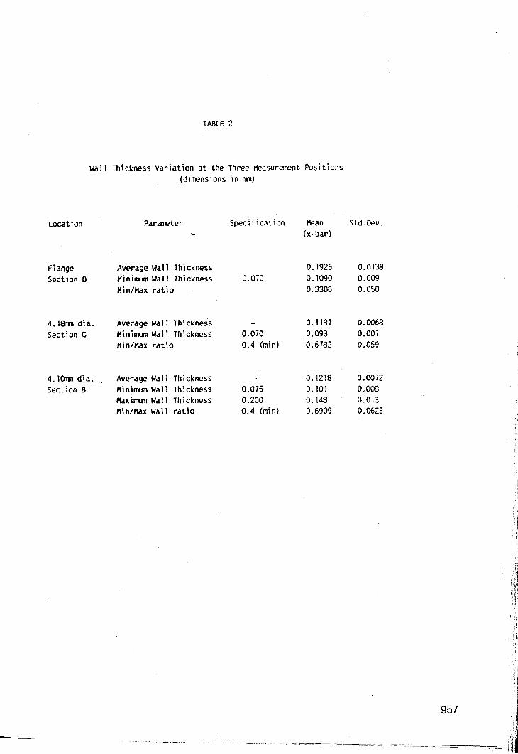
F r o m a cons ide ra t ion of screen func t ion discussed above, t h e screen design shown in Figure 3 was suggested. Screens of this pat tern were be fitted on either side of the arrays of masters with the slots of the screen situated between the masters thus preventing direct exposure of t h e masters to the anode. The jig model l ing p rogramme was used to p red ic t o p t i m u m slot profile and screen separation. Figure 4 shows a typical modelled geometry and Figure 5 a predicted current dis t r ibut ion plot which is directly proportional to the predicted nickel thickness.
-7-

950
The slot profile controlled the thickness variation along. the length of the master. T h e screen separa t ion had a marked effect on the circumferent ia l thickness variation. The optimum screen separa t ion was predicted a t 8 mm; above this va lue (i.e. screens fu r the r f rom the masters) deposi t ion was favoured o n the outer faces of the components but with a screen separation of less than 8 mm ( screens closer to the masters ) deposi t ion was favoured between the masters. The modelling also predicted that under optimum conditions, the wall thickness specification could be met.
Screens conforming to the optimum design predicted by the computer modelling programme were manufactured f r o m glass fi l led polycarbonate shee t , a rigid p l a s t i c ma te r i a l t h a t is s t a b l e in t h e e l ec t ro fo rming so lu t ion . T h e s c r e e n thickness was 10 mm but to achieve a f la t screen, the stressed surface of thicker sheet was first machined away. T h e screens were cut on a CNC machine to obtain the required very accurate pitching of the slots.
The screens were fi t ted to a jig fabricated in stainless steel and insulated with a PVC coating. It was impracticable to use a single screen to cover the length of 10 ladders, i.e. 1200 mm, as a screen of this length would be too flexible and the mismatch of coefficients of the rma l expansion between the polycarbonate and stainless steel would result in a n accumulated pirching error of more than 1 mm between o n e end of the screen and the other . This amount of pitching er ror would nullify the beneficial effects of the screen. Four screens were therefore specified, each pair of screens covering 2 arrays of 5 ladders. Each screen was fixed a t one end and allowed to expand a t the other end. At this length (700 mm) the screens were sufficiently flexible to give a variable screen separation over their length. An additional support was therefore provided at the mid-point of each screen t o maintain a precise separation over the whole length.
T h e electroforming trials with these screens were generally in agreement with the predict ions of the computer modelling, and confirmed tha t the op t imum screen separa t ion was 8 mm. Nickel thickness was fairly uniform around the circumference of the shank a n d the thickness was more va r i ab le a r o u n d the f lange, again in ag reemen t with the computer prediction. However, in some electroforming trials, wall thickness var ia t ion a round the circumference was unexpectedly high. This variation took the form of one half of the electroform being thicker than the other and the variation being more pronounced nearer the tapered section (sect ion B Fig.2) than near the flange (section C Fig.2). This thickness variation resulted f rom the masters not sitting vertically between the screens but angled towards one of the screens. Where the master was closer to the screen, the resulting nickel thickness was reduced but on the opposite side of the master , the dis tance f rom the screen was increased with a corresponding increase of nickel thickness. A modification to the jig design to ensure that the masters were always positioned vertically between the screens completely cured this problem.
An extended series of electroforming trials was carried out with this j ig/screen design culminating in a 26 jig run experiment producing 7800 electroforms. The 2 electroforms at each end of the array of 5 ladders were significantly thicker than the remainder and were rejected and not included in the assessment of the performance of the screens. Thickness measurements were made (see Fig.2), on
-8-
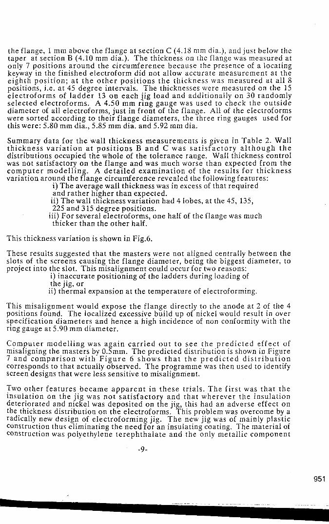
the flange, 1 mm above the flange a t section C (4.18 mm dia.), and just below the taper a t section B (4.10 mm dia.). The thickness on the flange was measured at only 7 posit ions a round the circumference because the presence of a locating keyway in the finished electroform did not allow accurate measurement at the e ighth pos i t ion ; a t t h e o t h e r pos i t ions t h e thickness was measured at a l l 8 positions, Le. at 45 degree intervals. The thicknesses were measured on the 15 e l ec t ro fo rms of l a d d e r 13 on each j ig load and additionally on 30 randomly selected electroforms. A 4.50 mm ring gauge was used to check the ou t s ide diameter of all electroforms, just in f ront of the flange. All of the electroforms were sorted according to their f lange diameters, the three ring gauges used for this were: 5.80 mm dia., 5.85 mm dia. and 5.92 mm dia.
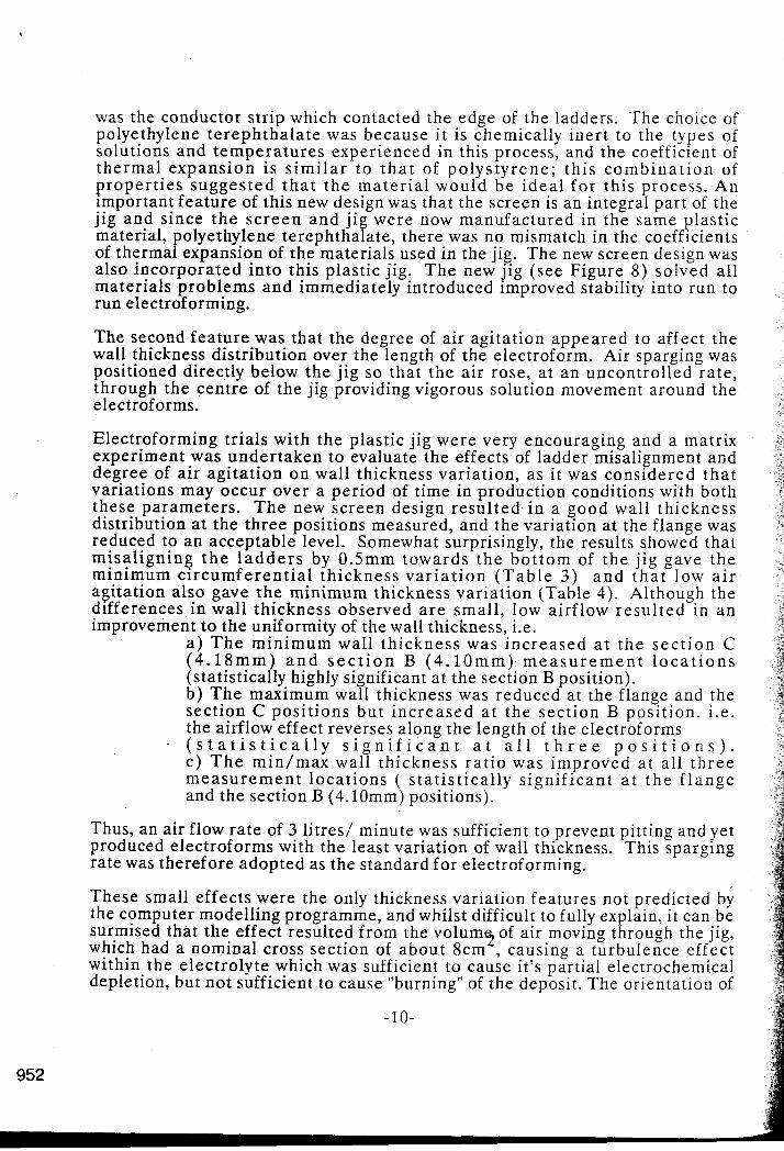
Summary da ta fo r the wall thickness measurements is given in Table 2. Wall t h i ckness v a r i a t i o n a t p o s i t i o n s B a n d C was s a t i s f a c t o r y a l t h o u g h t h e distributions occupied the whole of the tolerance range. Wall thickness control was not satisfactory on the flange and was much worse than expected f rom the c o m p u t e r model l ing . A d e t a i l e d examinat ion of the resu l t s f o r th ickness variation around the flange circumference revealed the following features:
i ) The average wall thickness was in excess of that required and rather higher than expected. ii) The wall thickness variation had 4 lobes, a t the 45, 135, 225 and 3 15 degree positions.
iii) For several electroforms, one half of the flange was much thicker than the o ther half.
This thickness variation is shown in Fig.6.
These results suggested that the masters were not aligned centrally between the slots of the screens causing the f lange diameter , being the biggest diameter, t o project into the slot. This misalignment could occur for two reasons:
i) inaccurate positioning of the ladders during loading of the jig, or ii) thermal expansion a t the temperature of electroforming.
This misalignment would expose the f l ange directly to the anode at 2 of the 4 positions found. The localized excessive build up of nickel would result in over specification d iameters and hence a high incidence of non conformity with the ring gauge a t 5.90 mm diameter.
Compute r model l ing was aga in c a r r i e d o u t t o s e e the p r e d i c t e d e f f ec t of misaligning the masters by 0.5mm. T h e predicted distribution is shown in Figure 7 and c o m p a r i s o n wi th F i g u r e 6 s h o w s t h a t t h e p r e d i c t e d d i s t r i b u t i o n corresponds to that actually observed. The programme was then used to identify screen designs that were less sensitive t o misalignment.
Two other fea tures became a p p a r e n t i n t h e s e tr ials. T h e f i r s t was tha t t h e insulat ion on t h e j ig was n o t sa t i s fac tory a n d tha t wherever t he insulation deteriorated and nickel was deposited on the jig, this had an adverse effect on the thickness distribution on the electroforms. This problem was overcome by a radically new design of electroforming jig. T h e new jig was of mainly plastic construction thus eliminating the need f o r a n insulating coating. The material of construction was polyethylene t e r eph tha la t e and the only metall ic component
-9-
95 1
was the conductor s t r ip which contacted the edge of the ladders. The choice of polyethylene t e r eph tha la t e was because i t is chemically iner t to the types of solutions and t empera tu res experienced in this process, and the coefficient of t he rma l expans ion i s s i m i l a r t o t h a t of po lys ty rene ; th i s c o m b i n a t i o n of p rope r t i e s sugges t ed t h a t t h e ma te r i a l would b e i d e a l f o r this process. An important fea ture of this new design was that the screen is an integral part of the j ig and s ince t h e s c r e e n a n d j ig were now manufactured in the same plastic material, polyethylene terephthalate, there was no mismatch in the coefficients of thermal expansion of the materials used in the jig. The new screen design was also incorpora ted in to this plastic jig. T h e new j ig ( see Figure 8) solved a l l mater ia ls problems a n d immediately introduced improved stability into run to run electroforming.
The second f ea tu re was that the degree of air agi ta t ion appeared to affect t he wall thickness distribution over the length of the electroform. Air sparging was positioned directly below t h e j ig so tha t t he a i r rose, a t a n uncontrol led ra te , through the cent re of the jig providing vigorous solution movement around the electroforms.
Electroforming t r ia ls with the plastic j ig were very encouraging and a matrix experiment was under taken t o evaluate the effects of ladder misalignment and degree of air ag i ta t ion on wall thickness var ia t ion, a s it was considered t h a t variations may occur over a per iod of time in production conditions with both these parameters . The new screen design resu l ted in a good wall th ickness distribution at the three positions measured, and the variation a t the flange was reduced to a n acceptable level. Somewhat surprisingly, the results showed that misa l ign ing t h e l a d d e r s by 0.5" towards t h e b o t t o m of t h e j ig gave t h e minimum c i r cumfe ren t i a l th ickness v a r i a t i o n ( T a b l e 3 ) a n d t h a t low a i r agi ta t ion also gave t h e minimum thickness var ia t ion (Table 4). Although the differences in wal l thickness observed a r e smai l , low airf low resu l ted in a n improvement t o the uniformity of the wall thickness, Le.
a ) T h e min imum wall th ickness was inc reased a t t h e s e c t i o n C (4.18") a n d s e c t i o n B (4.10") m e a s u r e m e n t l o c a t i o n s (statistically highly significant a t the section B position). b ) T h e maximum wall thickness was reduced at the flange and the sect ion C pos i t ions bu t i nc reased a t the sec t ion B posi t ion. i.e. the airflow effect reverses along the length of the electroforms
~ ( s t a t i s t i c a l l y s i g n i f i c a n t a t a l l t h r e e p o s i t i o n s ) . c ) T h e min /max wal l th ickness r a t io was improved a t a l l t h r e e m e a s u r e m e n t loca t ions ( s t a t i s t i ca l ly s ign i f i can t a t t h e f l a n g e and the section B (4.10") positions).
Thus, an air flow ra te of 3 l i tres/ minute was sufficient to prevent pitting and yet produced electroforms with the least variation of wall thickness. This sparging rate was therefore adopted as the standard f o r electroforming.
These small effects were the only thickness variation features not predicted by the computer modelling programme, and whilst difficult to fully explain, it can be surmised that the effect resulted from the volum5of air moving through the jig, which had a nominal cross sect ion of abou t 8cm , causing a turbulence effect within the electrolyte which was sufficient to cause it's partial electrochemical depletion, but no t sufficient to cause "burning" of the deposit. The orientation of
- 10-
952

t h e masters influenced the a reas within the jig where this turbulence occured, which resulted in a localised disruption in the continuity of the electrolyte. This i n turn can result in an increase in the local solution resistance causing. subtle changes in current densities in the immediate area, thus affecting the thickness of metal deposited.
Pi lot Sca le Evaluation
T h e work d e s c r i b e d above demons t r a t ed tha t i t was f eas ib l e to design an electroforming jig capable of controlling the nickel thickness to conform with the specification. The next s tep was to determine if the thickness variation could be controlled when using multiple jigs over several electroforming cycles. A pilot line was installed to carry out this evaluation.
T h e p i lo t l ine o p e r a t i o n was p l anned to b e representa t ive of the proposed production line operation, thus the pilot line had to be a single module of the m u l t i - m o d u l e p r o d u c t i o n f a c i l i t y . A p r o d u c t i o n f a c i l i t y c a p a b l e of electroforming up to 35 mill ion componen t s p e r a n n u m was r equ i r ed . T h e electroforming jigs accommodated 20 ladders of 15 masters in 2 parallel arrays, thus the simultaneous electroforming of 50 jigs was necessary . A convenient design for the production line was a line of 10 tanks each holding 5 jigs. Thus the pilot .. line was designed around a single e lectroforming tank accommodating 5 JlgS.
To achieve the small variation of wall thickness demanded by the specification, close control of cur ren t and electrolysis t ime t o each j ig was essent ia l . T o eliminate the effects of varying contact res is tance between jigs and jig to j ig in te rac t ions inf luenc ing m e t a l d i s t r i b u t i o n , t h e e l e c t r o f o r m i n g t a n k was des igned so t h a t e a c h j i g s a t i n i t s own cel l e lectr ical ly i so la ted f r o m its neighbours. This was achieved by using PVC panels to divide the tank into 5 equivalent compartments . Since each j ig was identical , the same current and electrolysis t ime would b e r e u i r ed f o r e a c h j i g every t ime. Th i s could b e achieved by using a single recti s i e r and connecting the 5 jigs in series. However, this arrangement lacks flexibility and all the 5 cells would have to be occupied for each cycle otherwise the circuit would be incomplete. In addition the wiring fo r this arrangement is complicated. A bet ter arrangement and the one adopted is to use a separa te rect i f ier f o r each jig. Although more expensive, because 5 rectifiers a re required, this arrangement allows independent electrical control on each j ig a n d hence t h e p la t ing c u r r e n t o r t ime fo r any jig can be varied independently of any other jig.
The rec t i f ie rs o p e r a t e d u n d e r cons t an t c u r r e n t con t ro l and a u t o m a t i c a l l y sequenced a p re - se t c u r r e n t s t epp ing regime a t the commencement of each electroforming cycle. E a c h rect i f ier had i ts own cur ren t x t ime total iser and automatically terminated the cur ren t supply t o the jig a f te r the passage of a pre-determined number of coulombs.
Air sparging was positioned immediately below each jig so that the air bubbles rose through the cent re of the jig providing vigorous solution agitation around the masters. Flow meters a n d valves were a d d e d so t h a t t he volume of a i r delivered to each jig could be independently adjusted and monitored.
-11-

T h e performance of the pilot electroforming l ine was qual i f ied by a f u r t h e r matrix experiment. The objective of the experiment was to assess how much of the overall variation of electroform wall thickness was due to the jigs, the cells and the electroforming runs. In addition, the reproducibilty and stability of the wall thickness during the pre-production trials was to be verified.
The electroforming for this experiment was conducted using the plastic jigs and the standard operating conditions with an air sparging rate of 3 l i t res l minute. 5 identical plastic jigs were manufactured to the opt imum design previously identified. The ladders were located 0.5 mm offset down in relation to the slots since this had been shown to give the most uniform wall thickness distribution.
15000 electroforms were produced in this experiment . Wall thicknesses were again measured at 23 positions on the middle electroform of each ladder. These results a re summarised in Tables 5 and 6.
The variation in mean wall thickness due to j ig t o j ig differences, cell to cell d i f fe rences a n d run to run d i f fe rences was very smal l , i.e. maximum mean difference in wall thickness was 0.003”. The jigs cells and runs all contributed equally t o the overall var ia t ion in mean wall thickness. These results confirm that the electroforming pilot line met its design cr i ter ia , i.e. the jigs and cells ope ra t ed independently of each other resulting in a high degree of control and consistency of wall thickness of the electroforms.
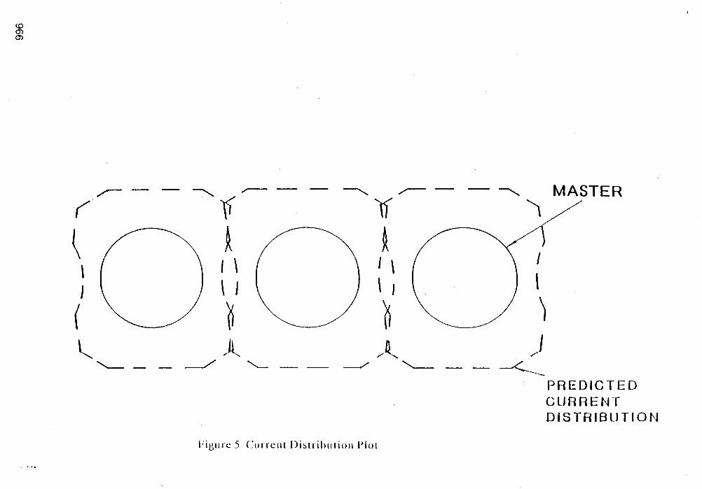
The high degree of control of wall thickness achieved with this design of jigs and electroforming l ine is shown in Table 7 a n d illustrated in Figs 9 to 11. These resu l t s conf i rmed tha t t he e l e c t r o f o r m i n g l i n e was c a p a b l e of p roduc ing e le c t rof o r ms that cons is t e n t ly complied with the specification .
By using careful experimental design, which helped to reduce any variations in the production conditions, the electroforming process benefitted by identifying any u n e x p e c t e d key f a c t o r s which would c a u s e v a r i a t i o n s in the p roduc t consistency. T h e use of Statist ical Process Cont ro l (SPC) methods helped t o i d e n t i f y c h a n g e s wh ich c a u s e d a v a r i a t i o n b e t w e e n b a t c h e s d u r i n g t h e development tr ials. A combina t ion of t h e s e two t echn iques resu l ted in t h e verification of proven Short Term Assessment Capability for the process in that i t was conf i rmed tha t t h e va r i a t ion in wal l th ickness p roduced d u r i n g t h e d e v e l o p m e n t p r o g r a m was suf f ic ien t ly s m a l l to o f f e r a s s u r a n c e tha t any production equipment using the same fundamenta l design cr i ter ia would also produce electroforms meeting the required specifications.
CONCLUSIONS.
1) T h e use of a plast ic jig with integral screens has resul ted in a n easy and c o n s i s t e n t m e t h o d of m a n u f a c t u r i n g h igh v o l u m e s of t h r e e d i m e n s i o n a l e l e c t r o f o r m s of complex des ign . T h e i n t e g r a t e d j i g design resu l ted in an improved wall thickness distribution of the electroforms.
2) Plating onto plastics can be successfully carried out by using plasma etching to act ivate the plast ic surface pr ior t o metal l isat ion. This e l iminates the use of harmful e t c han t s, thus off e ring an “environment ally friendly ” system.
- 12-
954

3) A mathematical modelling computer program developed by the University of S h e f f i e l d h a s b e e n s h o w n t o b e c a p a b l e of a c c u r a t e l y s i m u l a t i n g a n electroforming process, and has allowed the rapid design of screens to improve the metal distribution of an electroform.
4) T h e use of Statistical Process Control techniques can offer major advantages in the design and development of manufacturing methods and is important f o r the identification and elimination of areas of possible production variation.
Acknowledgement.
T h e a u t h o r s wish to acknowledge the invaluable contr ibut ions made to this project by Charles Packham, Keith Downing, David Keen, Leroy Abbott , Gordon Mann and many o thers in the Gi l le t te Technical Community. Thanks a re also due to The Gillette Company for giving permission to publish this work.
- 13-

TABLE 1
956
Wall thickness specification for electroform
1 . At the 4.lOmn diameter (section 6, fig.2).
a. 0.075mn minim
b. ratio of thinnest to thickest section: 0.4 m i n i m
c. 0 . 2 O h maxi”
2. At the 4.18mn diameter (section C, fig.2)
a. 0.07h-n minhnm
b. ratio of thinnest to thickest section: 0.4 m i n i m
c. 0.2- mximm with overall outside diameter not to exceed 4.55mn
3. At the flange (section 0, fig.2)
a. 0.0751m minim
h. m a x i m outside diameter: 5.90nm
Hardness XO-375 HV
Ducti 1 i ty (elongation) not less than 62
i
Location
F 1 ange Section D
TABLE 2
Ma11 Thickness Variation at the Three Measurement Positions (dimensions in mn)
4. lrhn dia. Section C
4. l h did. Section 6
Parameter Speci f i cat i on ..,
Average Ual1 Thickness H i n ~ m m Wall Thickness 0.070 nin/nax ratio
Average Wall Thickness - ninimm U a l l Thickness 0.070 Hin/Mx ratio 0.4 (min)
Average Ual1 Thickness - Hinimun Wall Thickness 0.075 Haximun Wall Thickness 0.200 nin/mx Wall ratio 0.4 (inin)
man (x-bar)
0.1926 0.1090 0.3306
0.1187 0.098 0.6782
0.1218 0.101 0.148 0.6909
Std. Dev.
0.0139 0.009 0.050
O.OOt% 0.007 0.059
0.0072 0,008 0.013 0.0623

TABLE 3
Effect on Thickness Variation of flisaligning the Ladders Relative to the Jig Screens
MSTER/SCREEN ALIGNHENT
6.M 0.Cmn d.%m Difference Pardmeter Location (a) (b) (C) (ax) Level of Significance
F lange 0.1793 0.1807 0.1769 0.0024 0.4536 (Hot significant) Av.Wall Thickness 4. lm Did 0. I162 0. I163 0. I169 6.0007 0.4636 (Hot significant)
F ckness 4
4
F ckness 4
4. IOmn Dia 0,1281 0. I275 0. I272 0.0009 0.6599 (Hot si&ificant)
ange 0.1125 0.1125 0. IO65 0.0060 0.2154 (Not significant) 1&m Dia 0,0995 0.0972 0.0940 0.0055 0.0388 (Significant) 1m Dia 0. 1082 0.1058 0. 1003 0.0079 0.0006 (Highly significant)
ange 0.2880 0.3032 0.3123 4.0243 0.0146 (Significant) lfm Did 0.1288 0.1342 0.1408 4.0120 0.0018 (Highly significant)
4.1Omn D i d 0.1415 0.1445 0.1523 -0.0108 0.0001 (Highly significant)
F 1 ange 0.397 0.377 0.344 0.053 0.0044 (Highly significant) flin/&x Ratio 4.18mn Did 0.775 0.726 0.671 0.104 0.0088 (Highly siynificant)
4.IOmn Did 0.766 0.742 0.660 0.106 0.0000 (Highly significant)
958

TABLE 4
E f f e c t o f A i r Agi tat ion Rate on Wall Thickness Var iat ion
AIRFLOW RATE
3 Itr/ 6 ltr/ 12 ltr/ minute minute minute Difference
ParMleter Location (a) (bl (c) . ( a x ) Level o f Significance
F 1 ange 0.1723 0.1783 0.1862 -0.0139 0.0045 (Highly s ign i f i can t ) Av.Wal1 Thickness 4,1&nn Oia 0.1156 0.1159 0.1 I79 -0.0023 0.0061 (Highly s ign i f i can t )
(n) 4.1Cmn Oia 0.1320 0.1280 0.1228 0.0092 0.0000 (Highly s ign i f i can t )
F 1 ange 0.1113 0. 1082 0.1120 -0.0007 0.5456 (Not s igni f icant) t!in.Uall Thickness 4.lEhn Oia 0.0987 0.0973 0.0947 0.0040 0.1250 (Not s ign i f i can t )
(m) 4.1On1n Oia 0.1118 0.1047 0.0978 0.0140 O.oo00 (Highly s ign i f
F 1 ange 0.2850 0.3032 0.3153 -0.0303 0.0062 (Highly s ign i f
(m) 4.lCmn Oia 0,1488 0.1469 0.1427 0.0061 0.0047 (Highly s ign i f Wx.Wal1 Thickness 4. lh Oia 0. I325 0.1330 0.1383 -0.0058 0.0495 (Signi f icant)
F 1 ange 0.397 0.362 0.356 0.041 0.0177 (Signi f icant)
4. lOnm Oia 0.753 0.715 0.690 0.063 O.OOO1 (Highly s ign i f i can t ) t!in/Nax Ratio 4 . 1 h Oia 0.749 0.734 0.688 0.061 0.0864 (Not signi f icant)
cant)
cant)
cant)

TABLE 5
Block N0. l
Variation of Average Wall Thickness in Electroforming Experiments
Run ID LOC. A 8 C O E F1. 0.1656 0.1673 0.1654 0.1652 0.1620
1 4.18 0.1065 0.1057 0.1066 0.1053 0.1060 4.10 0,1260 0.1227 0.1240 0.1233 0.1218 F1. 0.1659 0.1580 0.1617 0,1596 0.1582
2 4.18 0 1064 0.1041 0.1025 0.1013 0.1012 4. IO 0.1241 0.1237 0.1210 0.1211 0.1189 FI. 0.1623 0.1544 0.1574 0.1617 0 1602
3 4.18 0.1018 0.1021 . 0.1020 0.1024 0.1031 4.10 0.1198 0.1239 0.1215 0.1210 0.1214 F1. 0.1602 0.1627 0.1641 0.1602 0.1643
4 4.18 0.1013 0.1031 0.1039 0.1015 0.1033 4.10 0.1216 0.1212 0,1219 0.1187 0.1208 F1. 0.1624 0.1600 0.1597 0.1616 0.1588
5 4.18 0.1077 0.1053 0.1057 0.1054 0.1063 4.10 0.1228 0.1203 0 1202 0.1198 0. I198
Block No.2
Run ID LOC. A 6 C D E F1. 0.1619 0.1633 0.1590 0.1588 0.1627
1 4.18 0.1056 0.1031 0.1047 0.1023 0.1035 4.10 0.1233 0.1204 0,1210 0.1198 0.1196 F1. 0.1592 0.1589 0.1581 0.1610 0.1606
2 4.18 0 1031 0.1041 0.1046 0.1034 0.1031 4.10 0,1238 0,1215 0.1221 0.1207 0.1226 F1. 0.1637 0.1641 0.1621 0.1588 0 1582
3 4.18 0.1054 0.1041 0.1034 0.1031 0.1022 4.10 0.1224 0,1229 0.1212 0.1215 0.1205 FI. 0.1588 0.1586 0.1624 0.1595 0.1632
4 4.18 0,1032 0.1024 0.1050 0.1047 0.1038 4.10 0.1226 0.1218 0.1206 0.1222 0.1198 F1. 0.1608 0.1587 0.1599 0.1634 0.1567
5 4.18 0.1044 0.1057 0.1043 0.1061 0.1047 4.10 0.1211 0.1189 0 1211 0.1230 0.1193
960

TABLE 6
Variation of Average Wall Thickness Ratio in Electroforming Experiments
Block N 0 . l ~- - Run ID Coc. A 8 C D E
F1. 0,3180 0.3239 0.3708 0.3624 0.4001 1 4, I8 0.7980 0.7751 0.8011 0.7942 0.7879
4.10 0.7636 0.7861 0.8129 0.7849 0.7854
2 4.18 0 7925 0.7946 0.7939 0.8060 0.7956 4.10 0.1849 0.7869 0.1835 0.1772 0.1709 F1. 0.3715 0.4200 0.3824 0.3783 0 3777
3 4.18 0.8066 0.7909 0,1789 0.8014 0.7940
FI. 0.3783 0.3960 0 . ~ 0 0.3748 0.3719
4.10 0.7756 0.7636 0,7616 0.7760 0.7799 F1. 0.3609 0.3950 0.3690 0.3748 0.3702
4 4.18 0.1748 0.8105 0.7709 0.8099 0.8010 4.10 0.7683 0.8117 0.7772 0.8053 0.8080 F1. 0.3915 0.3720 0.3191 0.3717 0.3768
5 4.18 0.7821 0.7902 0.7749 0.7776 0.7841 4.10 0.1155 0.7784 0 7639 0.7667 0.7742
Block No.2
Run ID LOC. A 8 C D E
FI. 0.3608 0,3606 0.4005 0.3725 0.3653 1 4.18 0.1951 0.7964 0.8126 0.7974 0.8098
4.10 0.8020 0.7877 0.7951 0.7904 0.7984 F1. 0.3670 0.3965 0.3849 0.8232 0.3916
2 4.18 0 1967 0.8084 0.7953 0.8159 0.8037 4.10 0.7881 0.7975 0.1902 0.7806 0.7848 F1. 0.3801 0.3635 0.3649 0.3648 0 3869
3 4.18 0.8112 0.8056 0.7913 0.7981 0.7913 4, IO 0.7854 0.8045 0.7840 0.7961 0.7624 FI. 0.3699 0.3643 0.3687 0.3744 0.3558
4 4.18 0.7885 0.7909 0.8175 0.8026 0.7980 4.10 0.7970 0.79% 0.8119 0,7964 0.1852 FI. 0.3602 0.3906 0.4055 0.3875 0.3819
5 4.18 0.8043 0.7970 0.7818 0.8056 0.8017 4.10 0.793 0.1342 0 1610 0 . m 5 0.7754

TABLE 7
Wall Thickness Variation of Electroforms Produced During Pi lot Evaluation
Locat ion Parameter Specification Man Std.Dev. ( 5 ) -3s i imit t3s 1 imit (X-bar)
Flange Average.Ua11 Thickness 0.1626 0.0104 0.1315 0.1938 Section D M i n i m Wall Thickness 0.07mn (Hin) 0.0967 0.0074 0.0745 0.1190
4.18rm Average Wall Thickness - 0.1047 0.0064 0.0855 0.1238 Oiarneter Hinimun Wall Thickness 0.07mn (Hin) 0.0925 0.0059 0.0749 0.1101 Section C Hin/tlax Wall Thick.Ratio 0.4 (flin) 0.7946 0.0417 0.66% 0.9196
4. I(hn Average Wall Thickness - 0.1217 O.OO80 0.0975 0. 1458 Diameter f l i n ~ m Wall Thickness 0 . 0 7 h (Hin) 0.1065 0.0081 0.08822 0.1309
tlaximm Wall Thickness 0.2” (Max) 0.1351 0.01 12 0.1016 0.1686 Section 8 Hin/l3ax Wall Thick.Ratio 0.4 (flin) 0.7904 0.0478 0.6470 0.9337

8 .O
n
Figure 1 Ladder with 15 mastcrs

A
964

,
G
e> t
d
2 3 30 L
'
.-
w n
0 z a
965
. .
- - . . .
Z
( \ I
I I
I I
966

Figure c 6 Cross section of electroform showing variation of wail thickness a round circumference
967

.
/ -7-4 /
LJ r - /
r( (
I Y I
\
0 7- - L---
\ L-
PREDICTED CURRENT DISTRIBUTION
Figtire 7 Current distribution plot f o r inisaligned masters

Figure 8 The polyethylene terephthalate jig
969

I 9
1 saa 4
I
i I
4
-3s I
I I I
I I
:ea i 4 I
I I
i I I , I
I
I
i , i I
I
^ ,
+?S
,
, I
I
I
I
I
I
1 - - i 3 i J
Figure 9 Wall thickness distribution a t flange (section D )
,
970

1- -1
, as
j a m o i e s : L800
,ye an : . : o L 5 5 i
f t d . Tlev: .01029:
:roc:ess C a p : = 3 s
Figure 10 Wall thickness distribution at 4.18 mm diameter (secrion C)
97 1
3008
2m
i BBB
0
LSL
; -3s . I
: I
: I . I
: I I
: I
: I I
: I I
1
. I
I I
I
I
I I
; I 1
: I I
i l
I
I 1
I I I I I I 1 I I I I I I
I
I
I
I I I I I
Sa mp t e s : Mean : .121687
S t d . 3 e v : . 0 1 2 6 2 8
P r o c e s s C a p : * 3 s
L a o 0 Cp: 1 .65
C p k : 1 . 2 3 2
k: . 2 5 3
CRX: 60.62
Figure 11 Wail thickness disrrihurion at 4.10 mm diameter (section 3)
972