MARS ROBOTICS EDUCATION POSTER … of Technological Design Mars Robotics Education Poster, Activity...
68
MARS ROBOTICS EDUCATION POSTER http://mars.jpl.nasa.gov/classroom Activity #1: Marsbound! Mission to the Red Planet Grade Levels: 5 -12 Time Frame: 45 - 60 minutes Background: i The full robotic mission to Mars. The curriculum guide for the full ! unit lists a number of variations on the basic activities. period, so that variation is featured here. The full ! unit, including all the . Learning Goals: Content Standard E: Marsbound! Mission to the Red Planet s a complete stand-alone activity. unit can be completed in two to three days and consists of five activities that cover the engineering design process in depth. In this activity, students are given a set of "equipment cards," which each represent a different system that might be used on a Each system has a mass, power, and budget cost. Students must ensure that their design has enough on-board power to drive all its systems, have a low enough mass that it can be launched with existing rocket boosters, and be inexpensive enough to fit within their pre-assigned budget. Marsbound The “Design Challenge” variation can be completed in a single class Marsbound materials listed below, can be downloaded from the World Wide Web at: http://marsbound.asu.edu Students will gain first-hand experience with the engineering design process by designing a robotic mission to Mars that satisfies all of the given goals and constraints. National Science Education Standards Abilities of Technological Design Mars Robotics Education Poster, Activity 1, Page 1
Transcript of MARS ROBOTICS EDUCATION POSTER … of Technological Design Mars Robotics Education Poster, Activity...
MARS ROBOTICS EDUCATION POSTER http://mars.jpl.nasa.gov/classroom
Activity #1: Marsbound! Mission to the Red Planet
Grade Levels: 5 -12 Time Frame: 45 - 60 minutes
Background:
i The full
robotic mission to Mars.
The curriculum guide for the full ! unit lists a number of variations on the basic activities. period, so that variation is featured here. The full ! unit, including all the
.
Learning Goals:
Content Standard E:
Marsbound! Mission to the Red Planet s a complete stand-alone activity. unit can be completed in two to three days and consists of five activities that cover the engineering design process in depth. In this activity, students are given a set of "equipment cards," which each represent a different system that might be used on a
Each system has a mass, power, and budget cost. Students must ensure that their design has enough on-board power to drive all its systems, have a low enough mass that it can be launched with existing rocket boosters, and be inexpensive enough to fit within their pre-assigned budget.
MarsboundThe “Design Challenge” variation can be completed in a single class
Marsboundmaterials listed below, can be downloaded from the World Wide Web at: http://marsbound.asu.edu
Students will gain first-hand experience with the engineering design process by designing a robotic mission to Mars that satisfies all of the given goals and constraints.
National Science Education Standards
Abilities of Technological Design
Mars Robotics Education Poster, Activity 1, Page 1

Materials Needed (per team of 4 students):
• Marsbound! Equipment Cards (http://marsbound.asu.edu) • Marsbound! Mission Design Worksheet (p. 5) • Marsbound! Design Challenge Quick Reference (p. 6)
Optional Materials:
• Marsbound! Design Mat • Marsbound! Student Guide • Marsbound! Teacher Guide • Marsbound! Quick Reference Sheet • Calculator • Six-sided die
Procedure:
In this activity, your students will participate in the “Design Challenge” variation of the full Marsbound! Mission to the Red Planet activity guide. Please feel free to have your students do all five activities in the full Marsbound! curriculum, however!
Distribute a deck of Marsbound! equipment cards to each team of students (four students per team is the recommended number). If you have them available, also give the Design Mat to each team as well. Each team will design their own mission to Mars in a way that satisfies the following constraints:
• The mission must be a lander or rover mission; i.e., it must be able to travel to the surface of Mars.
• The spacecraft should be able to provide power for all the systems on board.
• The spacecraft should be able to be launched by one of the six red “booster cards” provided in the card deck.
• The entire mission cannot cost more than $250 million dollars.
• The mission should provide the maximum “Science Return” possible; i.e., it should have the maximum number of cards that include the text “Science Return +1” and “Science Return +2,” while still meeting the above constraints.
Students should be given total freedom in how they approach their design. Some students will begin by putting every system imaginable into their spacecraft – and will quickly realize that it is too heavy to launch! Other students will start with just the bare
Mars Robotics Education Poster, Activity 1, Page 2

minimum systems needed to get to Mars, without being able to do anything once they get there. Either approach is completely valid. Because the design process is iterative, it doesn’t matter where they enter it! All students will eventually arrive at a final design.
Before your students begin their work in earnest, call their attention to the six “green cards” in their decks. One of these cards will be drawn at random when their mission “launches.” Three of the cards are “spin-offs” (commercial applications of space technology), which effectively give the team more money to spend. The other three cards represent problems that can occur when designing a mission. Your students will have to decide how much they are willing to spend on backup systems and other “risk assessment” issues! When the students have completed their designs, have them draw one of the green cards at random to “launch” their mission.
Have your students finish up their designs approximately 10 minutes before the class session ends (you will need to give them a 15- and 5-minute warning, as they will want to tweak their design right until the very end!). Have each team report the amount of money they spent and the science return they achieved. The team with the greatest science return is the “winner”! In the event of a tie, the team that spent the least amount of money will be declared the winner of the challenge.
Assessment:
Students will submit a “design worksheet” that lists all of the components of their design. This design worksheet should demonstrate that the mission meets all of the above goals and constraints.
Vocabulary (from the Marsbound! equipment cards):
• Booster • Solar Power Cell • Resolution • Reliability
Mars Robotics Education Poster, Activity 1, Page 3
Age-Level Adaptations/Extensions:
Younger students will need more time with the calculators to add up the power, mass, and cost totals for the various iterations of their design. Consider laying out the basic components that every mission design needs (the items listed as “Required” on the card text and on the Design Mat) ahead of time so that the students can get a head start into the process.
Older students can consider additional constraints. For example, different power supplies can operate in different regions of Mars and for different lengths of time. Consider expanding the “victory conditions” to include these other constraints (requiring the students to perform research into the different areas on Mars that may be of interest to their mission). Older students should be encouraged to spend more time with risk assessment as well, perhaps even requiring backup systems for critical components in the base design. The six blank cards can also be customized to provide even more challenges for your older students!
“High-Tech” Adaptations/Extensions:
A spreadsheet is an excellent way to keep up with design changes and quickly recalculate totals for power, mass, and cost. This adaptation is also a great opportunity to improve your students’ computer applications skills!
Credits:
Keith Watt, M.A., M.S. ASU Mars Education Program Mars Space Flight FacilityArizona State [email protected]
(480) 965-1788
Mars Robotics Education Poster, Activity 1, Page 4
Name: ________________________________
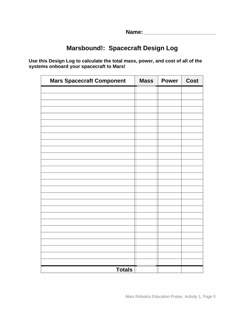
Marsbound!: Spacecraft Design Log
Use this Design Log to calculate the total mass, power, and cost of all of the systems onboard your spacecraft to Mars!
Mars Spacecraft Component Mass Power Cost
Totals
Mars Robotics Education Poster, Activity 1, Page 5
Marsbound! Mission to the Red Planet “Design Challenge” Quick Reference
Here are some things to keep in mind:
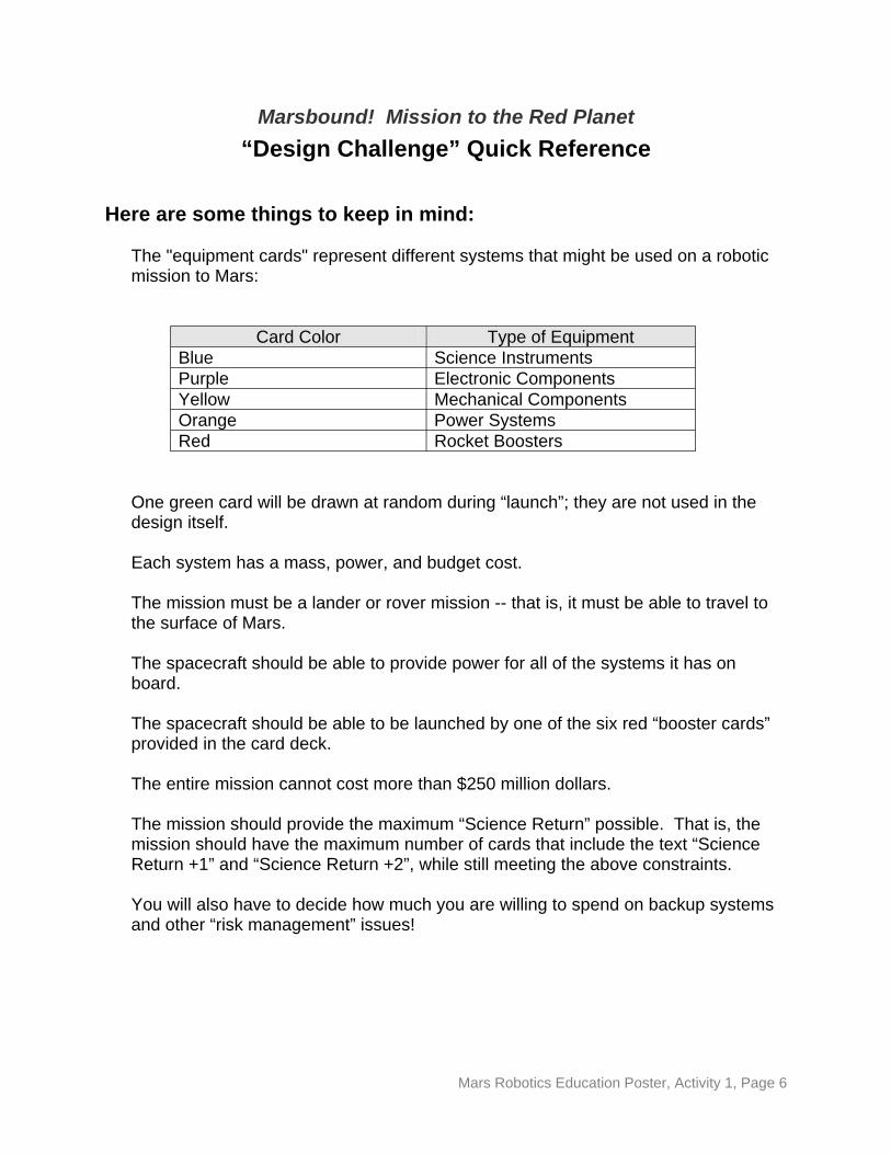
The "equipment cards" represent different systems that might be used on a robotic mission to Mars:
Card Color Type of Equipment Blue Science Instruments Purple Electronic Components Yellow Mechanical Components Orange Power Systems Red Rocket Boosters
One green card will be drawn at random during “launch”; they are not used in the design itself.
Each system has a mass, power, and budget cost.
The mission must be a lander or rover mission -- that is, it must be able to travel to the surface of Mars.
The spacecraft should be able to provide power for all of the systems it has on board.
The spacecraft should be able to be launched by one of the six red “booster cards” provided in the card deck.
The entire mission cannot cost more than $250 million dollars.
The mission should provide the maximum “Science Return” possible. That is, the mission should have the maximum number of cards that include the text “Science Return +1” and “Science Return +2”, while still meeting the above constraints.
You will also have to decide how much you are willing to spend on backup systems and other “risk management” issues!
Mars Robotics Education Poster, Activity 1, Page 6
MARS ROBOTICS EDUCATION POSTER http://mars.jpl.nasa.gov/classroom
Activity #2: Rover Parts - Sensors, Actuators, & Processors
Grade Levels: 5 - 12 Time Frame: 15 - 20 minutes
Background:
This activity introduces two of the three major components that go into every robot: sensors for determining its environment and actuators for affecting its environment. Students will be presented with real-world robots and asked to identify what parts are sensors and what parts are actuators. This activity also serves to expose students to the way in which robots are being used in our daily lives -- they may be surprised to learn just how common robots really are!
Sensors are what the robot uses to gather data about the world around it. Cameras and touch sensors are very common, but some robots use temperature, humidity, or even pH sensors. The smoke detector installed in your home uses a carbon-monoxide sensor to determine if there is a fire in the house. Some sensors are a bit more mundane, but no less important. The switch that controls your refrigerator light, mounted in the door, is a sensor that detects the state of the door (open or closed). A sensor, by itself, does nothing but provide data. It is up to other parts of the robot to actually do something with that data.
Actuators are what the robot uses to affect the world around it. An actuator may be a motor that moves a robotic arm, wheels that move the robot across a surface, or something as simple as a light that the robot can turn on for illumination or to signal its controller. In a smoke detector, the alarm is an actuator. In your refrigerator, the interior light is an actuator. Anything that allows the robot to make a change in its environment falls into this category. In a sense, actuators provide the output that results from the input provided by the sensors.
Most robots have a third component: a processor that is able to take input from the sensors, make decisions based upon that input, and control its actuators to respond to those decisions. Some robots have processors that are not this complex -- they can only perform a pre-determined set of instructions (or a single instruction) over and over. For example, both the smoke alarm and the refrigerator have a single instruction they can follow. When the smoke alarm’s sensors tell the processor that they detect smoke, it sounds the alarm. When the refrigerator’s switch tells the processor (a simple circuit, in this case) that the door is open, it turns on the light. Some robots, such as NASA’s
Mars Robotics Education Poster, Activity 2, Page 1
Mars exploration spacecraft, have very sophisticated processors that are able to take in data from a wide variety of sensors and make intelligent decisions based on that data. Students will gain more experience with robot processors in Mars Robotics Poster Activity #8: Rover Races.
Learning Goals:
Students will learn to identify the critical components that go into constructing a robot.
National Science Education Standards
Content Standard E: Understandings about Science and Technology
Materials Needed:
• Mars Exploration Rover diagram • Robot pictures • Student Activity Sheet and Picture (one per team of 4 students)
Optional Materials:
• None
Procedure:
This activity is very straightforward. Begin the discussion by describing sensors and actuators and the difference between them (sensors take in information from the environment, actuators act upon the environment). Show the students the diagram of NASA’s Mars Exploration Rover and have them decide whether each of the listed parts is a sensor or an actuator.
When your students have the basic idea of “sensors = input, actuators = output,” display photos of various machines and robots (several are included with this activity on pages 6-8. Ask the students to identify the sensors and actuators in each device. Finally, ask your students to look around the room and identify devices that have sensors and actuators and discuss the role each part plays in the device. As a check of the students’ understanding, give them the photo of the refrigerator and have them identify all the sensors and actuators they can!
Assessment:
When presented with a picture of a robot, or with the device itself, students should be able to identify the sensors and actuators in the device and what role those parts play.
Mars Robotics Education Poster, Activity 2, Page 2
Vocabulary:
• Sensor • Actuator • Processor
Age-Level Adaptations/Extensions:
Younger students, being concrete operations thinkers, may need to see the physical devices rather than pictures in order to gain a complete understanding of the concepts. (You should be aware that most smoke detectors have a small radioactive chip installed in them. While this chip is harmless, some parents may object to having the physical smoke detector available for close inspection. We leave that decision to you!)
Older students should be able to discuss devices outside of the classroom that have sensors and actuators. Encourage them to think of examples from their own experience.
“High-Tech” Adaptations/Extensions:
Use a commercial computerized robotics kit to construct an actual robot. Discuss with your students what each sensor and actuator does. Have your students characterize the components by describing what types of input each sensor can take as well as how sensitive it is. Have the students describe the power output of the different motors, as well as how fine a control can be achieved with them.
Credits: Keith Watt, M.A., M.S. ASU Mars Education Program Mars Space Flight Facility
Arizona State University [email protected]
(480) 965-1788
Mars Robotics Education Poster, Activity 2, Page 3
Answer Key for Robot Pictures
Page 1:
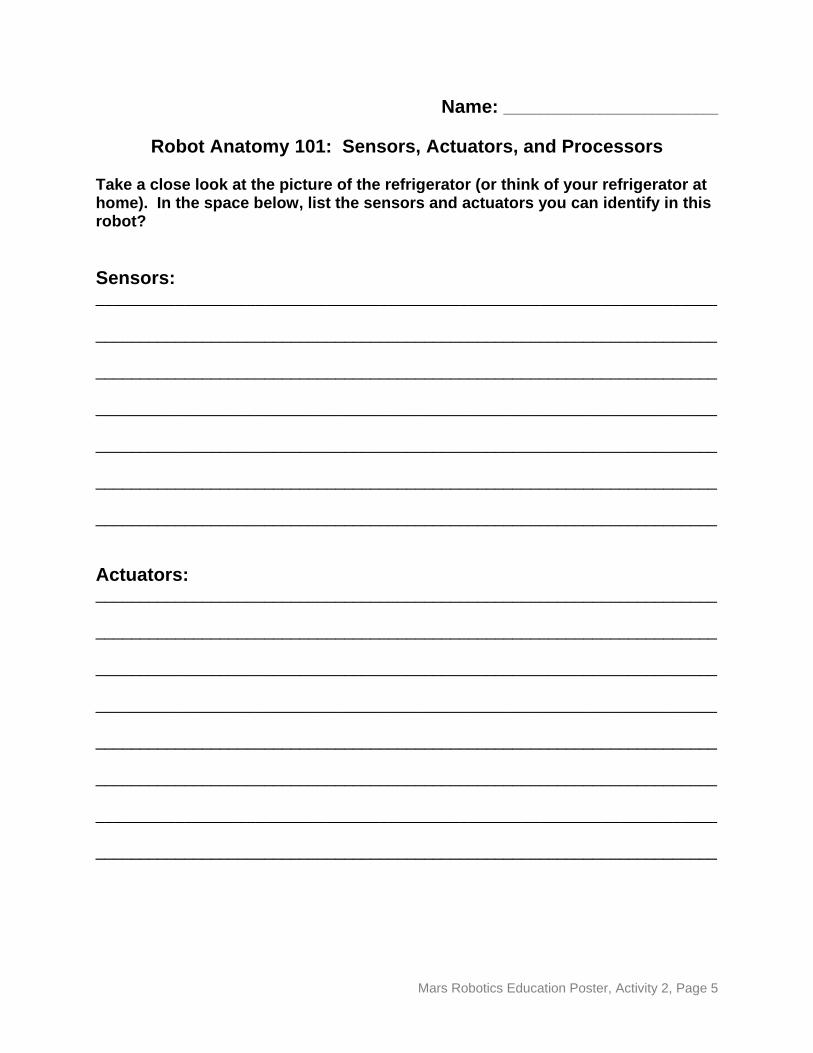
Smoke Alarm
Sensors: Carbon-monoxide-level detector, battery-voltage detector Actuators: Alarm
Night light
Sensors: Light-level detector Actuators: Light
Page 2:
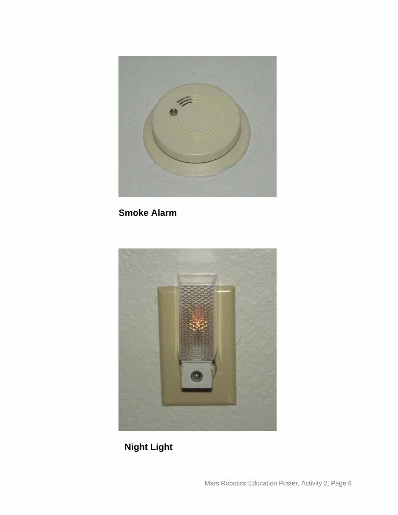
Stove
Sensors: Temperature sensor Actuators: Heating elements
Garage door opener
Sensors: Radio-command receiver Actuators: Door-opening motor, garage light bulb
Page 3:
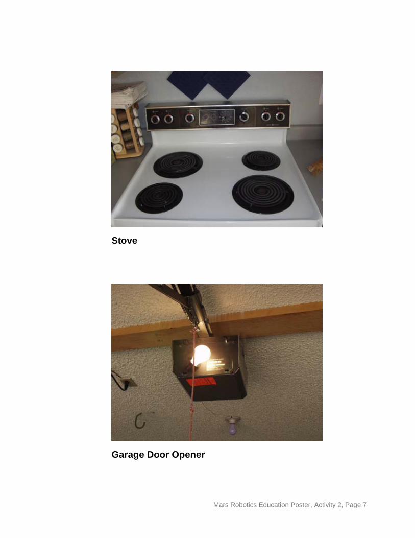
Thermostat
Sensors: Temperature sensor Actuators: Heating/air-conditioning controller
Toaster
Sensors: Temperature sensor Actuators: Heating elements, spring lifter
Pages 4 and 5 (Student Photo and Questions):
Refrigerator
Sensors: "Door open" switch, temperature sensor, ice-level sensor (in ice maker), frost-level sensor Actuator: Condenser motor, ice-maker motor, interior light
Mars Robotics Education Poster, Activity 2, Page 4
______________________________________________________________________
______________________________________________________________________
______________________________________________________________________
______________________________________________________________________
______________________________________________________________________
______________________________________________________________________
______________________________________________________________________
______________________________________________________________________
______________________________________________________________________
______________________________________________________________________
______________________________________________________________________
______________________________________________________________________
______________________________________________________________________
______________________________________________________________________
______________________________________________________________________
Name: _____________________________
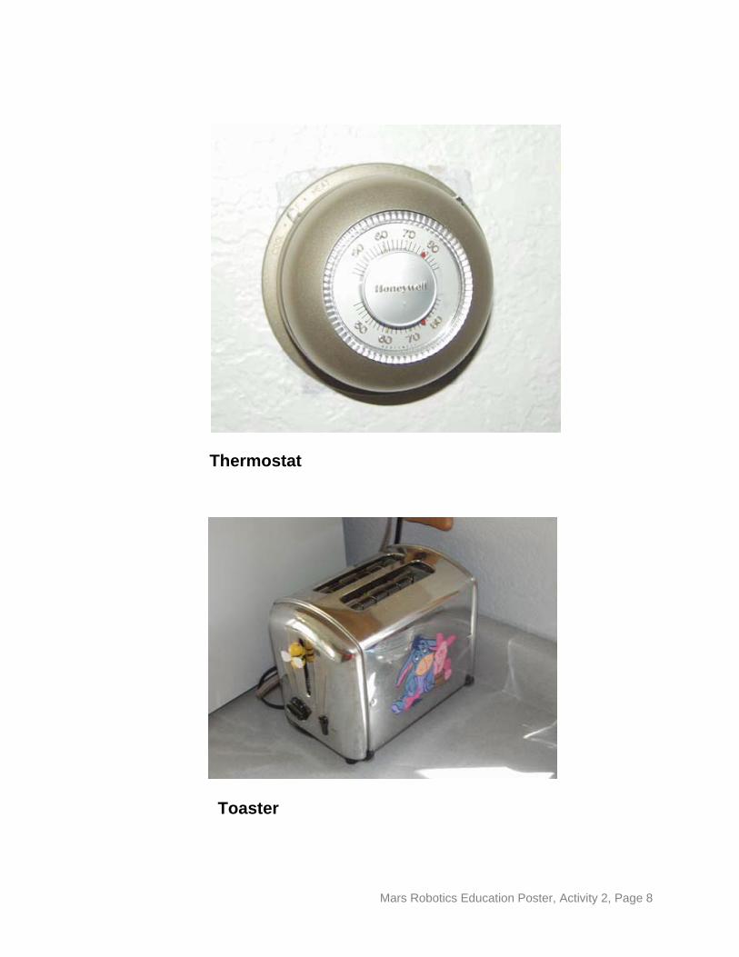
Robot Anatomy 101: Sensors, Actuators, and Processors
Take a close look at the picture of the refrigerator (or think of your refrigerator at home). In the space below, list the sensors and actuators you can identify in this robot?
Sensors:
Actuators:
Mars Robotics Education Poster, Activity 2, Page 5
Smoke Alarm
Night Light
Mars Robotics Education Poster, Activity 2, Page 6
Stove
Garage Door Opener
Mars Robotics Education Poster, Activity 2, Page 7
Thermostat
Toaster
Mars Robotics Education Poster, Activity 2, Page 8
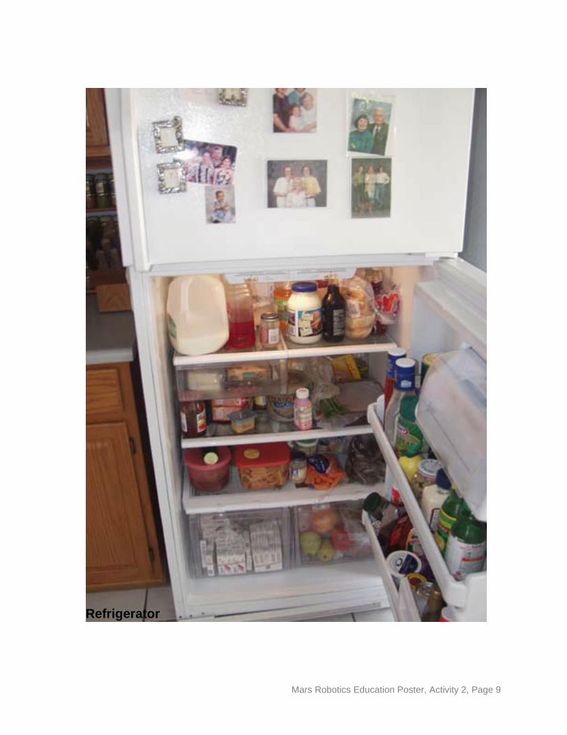
Refrigerator
Mars Robotics Education Poster, Activity 2, Page 9
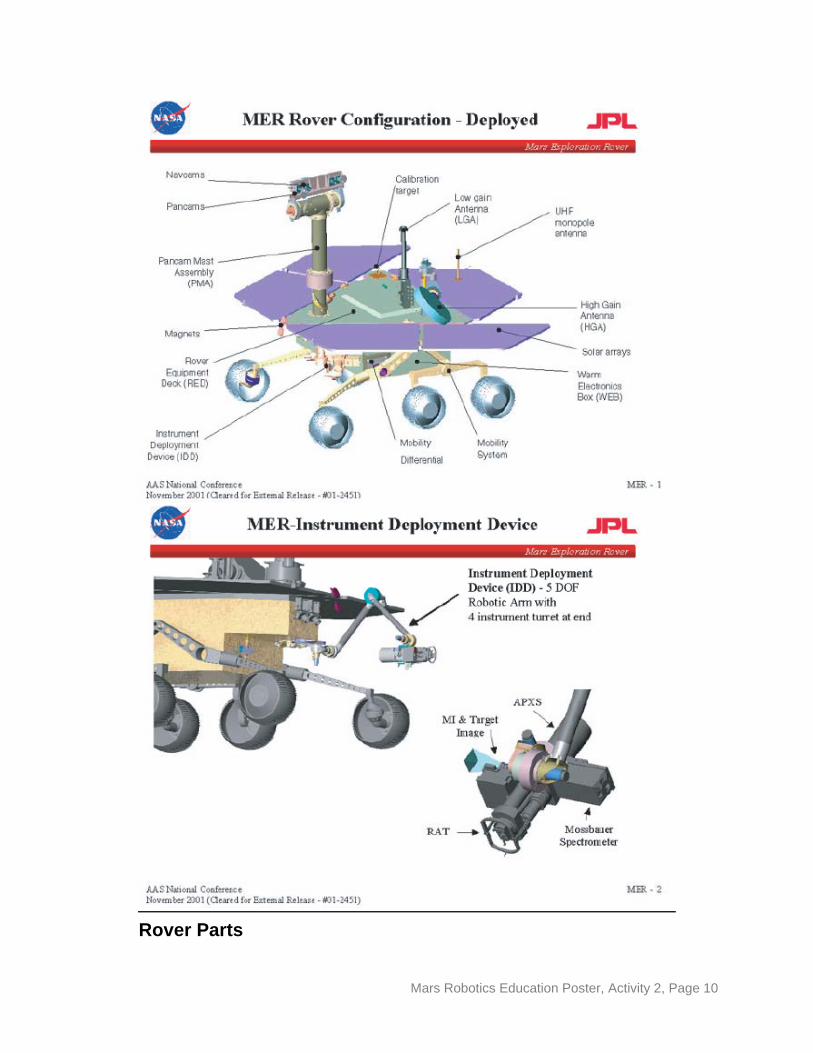
Rover Parts
Mars Robotics Education Poster, Activity 2, Page 10
MARS ROBOTICS EDUCATION POSTER http://mars.jpl.nasa.gov/classroom
Activity #3: Out of this World Launch
Grade Levels: 5 - 12 Time Frame: 2 or 3 45-minute class periods
Background:
Getting from Earth to Mars is not easy! Not only do we have to find a way to give the spacecraft enough energy to leave the Earth’s surface, we also have to give it enough energy to leave the influence of the Earth’s gravity entirely. When the spacecraft arrives at Mars, even more energy is needed to slow it down so that it can land safely on the surface of the red planet. Just giving the spacecraft enough energy isn’t enough, however. We also have to make certain that the spacecraft manages to hit its target! Trying to navigate to Mars with a spacecraft is like trying to roll a quarter into a slot one hundred yards away. The slightest error in the launch trajectory turns into a rather spectacular miss at the end of the spacecraft’s journey! Energy to lift the spacecraft to Mars and guidance to ensure the spacecraft arrives on-target are the two biggest challenges in getting to Mars.
Currently, the only way to provide a spacecraft with enough energy to reach Mars is to use chemical-fueled rocket boosters. One booster used by NASA for its recent orbiters and rovers is the Boeing Delta II, a forty-meter (131-foot) rocket capable of generating 485,700 newtons (109,135 pounds) of thrust. This powerful thrust allows the rocket to reach a maximum speed of over 28,000 kilometers per hour (17,400 miles per hour), which is fast enough to escape the gravitational influence of the Earth. Sophisticated on-board and ground-based computers monitor the spacecraft’s trajectory to ensure that the spacecraft arrives safely at Mars. The rocket’s sensors take in data that allows its processor to determine the rocket’s current position. If a course correction is necessary, ground controllers on Earth can instruct the rocket’s processor to fire its thrusters (which are actuators) to make the change. Because of fuel limitations, however, only very small corrections can be made in the trajectory of the spacecraft. Thus, it is critical for the rocket to be on the correct path right from launch.
In this activity, your students will be introduced to the energy and guidance problems that are faced by NASA engineers every time they send a rocket into space. They will be tasked with launching a payload (using a rubber-band-powered “launcher”) from a starting base and having the payload successfully “land” at a predetermined landing
Mars Robotics Education Poster, Activity 3, Page 1
site. The students will have to adjust the energy imparted to their “spacecraft” and will also have to consider how they will control the craft so that it arrives on target.
[NOTE: The projectiles used by the students in this activity are not true “rockets” because they do not get their thrust from the application of Newton’s Third Law of Motion. The key factors in this activity, energy and guidance, are the same, however.]
Learning Goals:
Using the results of their experiments, students will create graphs of physical variables and use these graphs to hit a pre-determined target with a projectile propelled by their launchers.
National Science Education Standards:
Content Standard B: Motions and Forces Content Standard E: Abilities of Technological Design Content Standard E: Understandings about Science and Technology
Materials Needed (per team of 4 students):
• Rubber bands • Measuring tape • Wooden dowels
(or unsharpened pencils) • White glue • Graph paper
• Craft sticks • Launch data log (p. 5) • Small ball • Target
Optional Materials:
• Small cylinder • Net
Procedure:
Mark off a “launch area” and a “landing site” in an area clear of obstructions and passers-by. Mark off “warning areas” to either side of the “test range” to ensure the safety of participants and observers.
Pass out the materials to each team. Instruct the students that they are to build a launcher that can propel their “spacecraft” (the ball) into the air and hit the “landing site.”
Students are free to construct any kind of launcher they wish. They key factor is that the amount of force applied to the ball must be repeatable so that the target can be hit
Mars Robotics Education Poster, Activity 3, Page 2
consistently. The launcher should allow for variable amounts of energy to be imparted to the ball and must be able to be positioned in such a way that it can provide the guidance needed to ensure the ball hits the target. Catapults, slingshots, and ramp launchers are very common solutions to these problems. Allow your students to use their own creativity, but if they seem at a loss for ideas, suggest one of these.
Students should mark their launchers in such a way that the energy imparted can be recorded (at least abstractly). For example, a catapult launcher may have notches numbered from 1 to 5; a slingshot launcher may have marks for actual distances the rubber band is pulled back.
Similarly, students should mark their launchers in such a way that the direction of launch can be recorded. A simple way is to mark angles on the floor with tape. The launcher’s direction can be recorded by referencing these marks. Note that very few launchers will throw the projectile exactly straight, so some offset is almost always required.
The students should conduct tests of their launcher at various energies and angles so that they can predict where the projectile will land under any combination of conditions. Students will plot their test results on graph paper and will use these graphs to predict the energy and guidance settings needed to hit the final target site.
During the final launch, students will be given one chance to hit the target. The distance the spacecraft lands from the target site will serve as the evaluation of their measurement and test skills. Note that the students should be able to determine the proper position and energy values for any target distance from their graphs, even if they never actually conducted a test at that distance!
At your option, use a net at the target site to catch the projectile. This net simulates the force applied by “aerobraking” upon arrival at Mars. Aerobreaking is a process that uses the friction of the martian atmosphere to slow spacecraft down. Each time the spacecraft dips into the martian atmosphere, its orbit size is also reduced. After many dips into the atmosphere, the spacecraft is in a more suitable orbit for science operations. NASA’s Mars Global Surveyor, Mars Odyssey, and Mars Reconnaissance orbiters were all designed to use aerobraking.
As an option, students could use a cylinder with cardboards fins. This option brings the guidance problem to a whole new level, as the students must now also design a spacecraft that is aerodynamically stable!
Mars Robotics Education Poster, Activity 3, Page 3
Assessment:
Students will submit their graphs detailing the results of their tests on their launcher and demonstrate their mastery of the measurement and design processes required. They will demonstrate their understanding of these graphs by using them to determine the position and energy needed for their final launch.
Vocabulary:
• Newton • Trajectory • Guidance
Age-Level Adaptations/Extensions:
For younger students, you should consider restricting them to a single type of launcher and having them control for a single variable (energy). In this case, you could either make the target area considerably bigger, or have the students strive to hit a particular distance, rather than distance and position.
Older students could use weights to measure the force needed to pull the rubber bands back a certain distance. Using these measurements in their proper units, students can plot the actual force vs. distance on their graphs instead of using the abstract measurements (“notch 1”, “notch 2”, for example) described above.
“High-Tech” Adaptations/Extensions:
This activity is perfectly suited for using chemical-powered model rockets. Each model rocket engine lists its rated thrust in newtons along with its burn time and coast time. Students can strive for altitude and the ability to hit a specific target upon recovery via parachute. Many different curricula are available for this basic task, including software that will graphically simulate the model rocket’s flight through the atmosphere – a very realistic and cost-effective way to conduct a test program!
Credits:
Keith Watt, M.A., M.S. ASU Mars Education Program Mars Space Flight FacilityArizona State [email protected] (480) 965-1788
Mars Robotics Education Poster, Activity 3, Page 4
Name: _____________________________
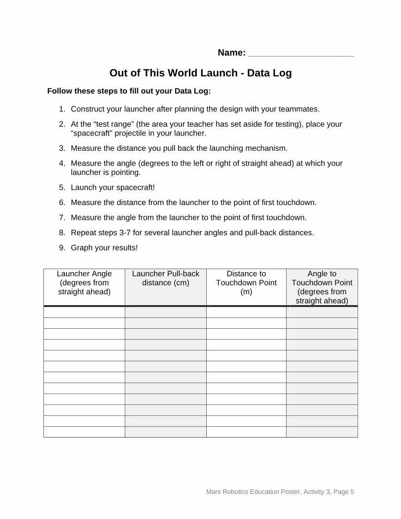
Out of This World Launch - Data Log Follow these steps to fill out your Data Log:
1. Construct your launcher after planning the design with your teammates.
2. At the “test range” (the area your teacher has set aside for testing), place your “spacecraft” projectile in your launcher.
3. Measure the distance you pull back the launching mechanism.
4. Measure the angle (degrees to the left or right of straight ahead) at which your launcher is pointing.
5. Launch your spacecraft!
6. Measure the distance from the launcher to the point of first touchdown.
7. Measure the angle from the launcher to the point of first touchdown.
8. Repeat steps 3-7 for several launcher angles and pull-back distances.
9. Graph your results!
Launcher Angle (degrees from straight ahead)
Launcher Pull-back distance (cm)
Distance to Touchdown Point
(m)
Angle to Touchdown Point
(degrees from straight ahead)
Mars Robotics Education Poster, Activity 3, Page 5
MARS ROBOTICS EDUCATION POSTER http://mars.jpl.nasa.gov/classroom
Activity #4: Entry, Descent, & Landing: Six Minutes of Terror
Grade Levels: 5 -12 Time Frame: 1 or 2 45-minute class periods*
*or construction time outside of class
Background:
In a variation of the classic "egg drop" experiment, students will be asked to design a rover using craft sticks that can survive a drop of approximately ten meters (~30 feet). Glue and craft sticks are the only other construction materials that can be used – no parachutes allowed! The rover’s “instrument package” will be represented by an approximately 1/2 kilogram (approximately 1 pound) weight, which must be incorporated into the students’ designs.
It should be stressed to the students that they will get only one chance to drop their rover. It must be sufficiently sound to survive the drop the first time. The real point of this activity, of course, is not whether or not the rover survives. The real question is: did the students devise a test, evaluation, and revision program that allowed them to demonstrate with absolute confidence that their rover WILL survive? They will be required to present their design before the drop attempt and the data that they have collected from their tests. Those presentations should convince listeners that their rover will, indeed, survive. The success of the drop itself should be a foregone conclusion!
This exact process was used when testing the Entry, Descent, and Landing (EDL) system for NASA’s Mars Exploration Rovers. We only had one chance to land the spacecraft on Mars, so we had to be absolutely certain the system would work properly before the spacecraft left the Earth!
Learning Goals:
Students will apply their knowledge of the test, evaluation, and revision process to design a robot that can survive a simulated entry, descent, and landing on the Martian surface.
Mars Robotics Education Poster, Activity 4, Page 1
Materials Needed (per team of 4 students):
• Craft sticks • White glue • ~ 1/2 kg (~1 pound) weight • Student data log (page 4)
Optional Materials:
• None
National Science Education Standards
Content Standard E: Abilities of Technological Design
Procedure:
Divide your students into teams (four members is a good number) and distribute the materials. Advise your students that they will be responsible for collecting data on each portion of their design, which will prove that their rover will survive the drop before the drop is attempted. Encourage them to break the rover down into smaller subsystems and to test and evaluate each of those systems individually. For example, they could build and test a “mobility” system or an “instrument deck” before building the entire rover. They should also experiment with different structural unit types, such as triangles or squares. (Note that for this activity these systems are intended to be “representative” – they don’t need to be functional!) They should brainstorm what subsystems their rover will need and what data they will need to collect to make their proof. You might consider putting the following questions on the board:
• What parts does the rover need to have in order to explore the martian surface? (You should encourage your students to include “models” of representative instruments such as cameras and antennas.)
• How big and heavy can the rover be and still be able to survive landing?
• What kind of structure will be least likely to break?
• What data should we gather to prove that these structures will survive?
After all teams have completed their testing and have assembled their rovers, have each group present their data to the class and get “launch authorization” from them. (All NASA spacecraft go through such design reviews prior to receiving launch approval.) When everyone has passed the review, proceed to the “launch site” and drop the rovers! Have students record their observations. Return to the classroom and lead a discussion of what they saw. What happened that they didn’t plan for? What data could they have gathered to test for these unexpected occurrences before launch?
Mars Robotics Education Poster, Activity 4, Page 2
Assessment:
The student team presentations serve as assessment for this activity. Students should demonstrate a thorough understanding of the test, evaluation, and revision process.
Vocabulary:
• Structure • Subsystem
Age-Level Adaptations/Extensions:
Younger students should not be expected to produce as much quantitative data as a result of their testing, but should still be able to describe the results of their testing in qualitative terms.
Older students should be expected to produce graphs of test data (for example, structural unit size vs. maximum drop height) or even computer models of their proposed design as part of their presentation.
“High-Tech” Adaptations/Extensions:
Instead of building the rover from craft sticks, students could design and build an actual computerized rover and then be tasked to develop an “entry, descent, and landing” system for it. Note that the risks of hardware breakage are very real – your students should definitely take the test and evaluation process very seriously!
Design, build, and a test a model rocket from parts. The rocket can be tested for stability by tying a string around its center of mass and whirling it around in a circle. Check the World Wide Web for a wealth of educational activities involving model rocketry; it’s the perfect introduction to real-world engineering design!
Credits:
Keith Watt, M.A., M.S. ASU Mars Education Program Mars Space Flight FacilityArizona State [email protected] (480) 965-1788
Mars Robotics Education Poster, Activity 4, Page 3
Name: _____________________________
Entry, Descent, and Landing: Six Minutes of Terror Data Log
Use this sheet to record your observations during your test, evaluation, and revision process. You should think about and answer the following questions as you conduct your tests:
• What parts does the rover need to have in order to explore the martian surface? • How big and heavy can the rover be and still be able to survive landing? • What kind of structure will be least likely to break? • What data should we gather to prove that these structures will survive?
____________________________________________________________________________________
____________________________________________________________________________________
____________________________________________________________________________________
____________________________________________________________________________________
____________________________________________________________________________________
____________________________________________________________________________________
____________________________________________________________________________________
____________________________________________________________________________________
____________________________________________________________________________________
____________________________________________________________________________________
____________________________________________________________________________________
____________________________________________________________________________________
____________________________________________________________________________________
____________________________________________________________________________________
____________________________________________________________________________________
____________________________________________________________________________________
____________________________________________________________________________________
Mars Robotics Education Poster, Activity 4, Page 4
MARS ROBOTICS EDUCATION POSTER http://mars.jpl.nasa.gov/classroom
Activity #5: Command and Control: Getting from Here to There
Grade Levels: 5 -12 Time Frame: 1 45-minute class period
Background:
Arriving at Mars is just the first step in achieving the goals of a mission to Mars. Engineers must also ensure that, when the spacecraft is on the surface of the planet, it is able to move precisely where and how it is told to move. Spacecraft on the surface of Mars, such as the Mars Exploration Rovers, have no way of directly determining where they are on the surface. There is no Global Positioning System at Mars! Engineers must know precisely how far and in what direction the rover has traveled from its starting point. In order to do this calculation, engineers must know how far the rover will travel at a particular power level in a particular amount of time, as well as how much the rover deviates from a straight-line course in that same amount of time. The process of measuring these characteristics is called calibration.
Every mechanical system needs to be calibrated in order to run smoothly, but in the case of Mars robots, it is critical. We cannot simply tell a rover to “go forward three meters,” since the robot has no way of measuring how far three meters on the surface of Mars is. Instead, we can tell the rover to “turn your motors on for ten seconds,” and, if we know from our calibration that the rover travels at a velocity of 0.3 meters per second, then we know that the rover will travel three meters. Similarly, if our calibration tells us that the rover drifts 50 centimeters to the left of straight in that three-meter distance, we know that we need to aim for a spot 50 centimeters to the right of the actual target point. Calibration allows the rover to navigate safely and accurately even when we are millions of kilometers away from it.
In this activity, your students will perform a simple calibration of a toy car and use that calibration to navigate to a target point on the floor. This activity is, not coincidentally, very similar in concept to Activity #3 (Out of this World Launch). Your students should begin to see that every system on the robot, from the robotic arm to the mobility system, needs to be calibrated. This calibration is performed in similar ways in every case.
Mars Robotics Education Poster, Activity 5, Page 1
Learning Goals:
Students will plot energy (in units of pull-back distance for a flywheel-driven car) vs. distance of travel and distance of travel vs. course deviation and will use these graphs to exactly hit a pre-determined target with their simulated rover.
Materials Needed (per team of 4 students):
• Toy flywheel-driven car (a car that can be pulled back and released to provide motion)
• Measuring tape • Command and control data log (page 5)
Optional Materials:
• Protractor • Stopwatch
National Science Education Standards
Content Standard B: Motions and Forces Content Standard E: Abilities of Technological Design Content Standard E: Understandings about Science and Technology
Procedure:
Pass out the materials to each team. [NOTE: A flywheel is a disk that is used to store energy for later release. A flywheel-driven car is a toy that (generally) is pulled back a short distance and released, allowing the car to travel freely forwards for a considerable distance.]
Have the students measure how far they pull back the car (thus energizing the flywheel), and then measure how far (straight-line distance) the car travels as a result. Also measure how far to the left or right the car drifts within that distance. Repeat this measurement for a number of starting energies. Students should define one direction (usually left) to be negative and the other to be positive for the purposes of graphing.
The students should produce two graphs of their results: pull-back distance vs. distance traveled and distance traveled vs. drift distance.
Test the students’ calibration by giving them a predetermined, exact distance to reach with their car. They will need to read off from their graphs how far back to pull the car and how much to correct for drift. The target distance does not need to be a distance they have tested previously!
Mars Robotics Education Poster, Activity 5, Page 2
Assessment:
Students will submit their graphs detailing the results of their tests on their car and demonstrating their mastery of the measurement processes required. They will demonstrate their understanding of these graphs by using them to determine the energy (pull-back distance) and drift correction needed to reach a predetermined, exact target.
Vocabulary:
• Flywheel • Drift correction • Calibration
Age-Level Adaptations/Extensions:
For younger students, you should consider having them control for a single variable (energy). In this case, you could either make the target area considerably bigger, or have the students strive to hit a particular distance, rather than distance and position.
Older students should measure the angle of drift vs. pull-back distance instead of the linear distance of the drift. This study is a more accurate calibration for the car. Additionally, older students can use a stopwatch and analyze the distance traveled to determine the velocity imparted to the car by the various flywheel energies, which is also a more useful calibration than just the distance traveled alone.
“High-Tech” Adaptations/Extensions:
This activity is fundamental prior to using commercial robotics kits, particularly if the robot is to be programmed ahead of time. Each motor used in the robot will have its own velocity and drift error that must be accounted for in the program that is controlling the robot. Accurate calibration of linear and turning velocity of the robot is critical to successful automated navigation.
Credits:
Keith Watt, M.A., M.S. ASU Mars Education Program Mars Space Flight FacilityArizona State [email protected] (480) 965-1788
Mars Robotics Education Poster, Activity 5, Page 3
Name: _____________________________
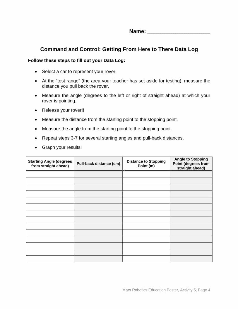
Command and Control: Getting From Here to There Data Log
Follow these steps to fill out your Data Log:
• Select a car to represent your rover.
• At the “test range” (the area your teacher has set aside for testing), measure the distance you pull back the rover.
• Measure the angle (degrees to the left or right of straight ahead) at which your rover is pointing.
• Release your rover!!
• Measure the distance from the starting point to the stopping point.
• Measure the angle from the starting point to the stopping point.
• Repeat steps 3-7 for several starting angles and pull-back distances.
• Graph your results!
Starting Angle (degrees from straight ahead) Pull-back distance (cm) Distance to Stopping
Point (m) Angle to Stopping
Point (degrees from straight ahead)
Mars Robotics Education Poster, Activity 5, Page 4
MARS ROBOTICS EDUCATION POSTER http://mars.jpl.nasa.gov/classroom
Activity #6: Descent into Endurance Crater
Grade Levels: 5 -12 Time Frame: 30-45 minutes
Background:
In June of 2004, NASA scientists decided to send the Mars Exploration Rover, Opportunity, over the edge of Endurance Crater, a huge, deep impact crater on the surface of Mars in the Meridiani Planum region. The science team knew that the rover might not be able to make it out of the crater, but it was decided that the potential science benefit outweighed the risk of getting stuck in the crater. The problem they faced, however, was how to get the rover down the side of the crater and safely back out without tipping over. If Opportunity did not make it safely to its science site on the crater wall, the mission team would lose the rover without gaining any science information at all. In order to find a safe route to the site, Opportunity’s navigators had to consider a variety of factors, each of which was essentially a force that would change the rover’s motion as it descended the crater wall.
All of physics begins with the study of forces and motion. Newton’s Three Laws of Motion describe how forces affect the motion of an object. They form the basis of most of physics – and of robotics! Newton’s Laws are just as valid on Mars as they are on Earth, but because Mars has one-third the gravity of Earth, rovers (and everything else!) will fall (or roll, in this case) much more slowly on the red planet. As you perform this activity, ask your students to think about how their results would be different had they performed the experiment on Mars.
This activity demonstrates to students that when a force (gravity in this case) is applied to a stationary object, it will experience an acceleration, that is, a change in velocity. The fundamental concept to be conveyed is that “forces cause a change in motion.”
Learning Goals:
Students will learn how an object’s motion can be described by its position and velocity and how forces can cause a change in the object’s motion.
Mars Robotics Education Poster, Activity 6, Page 1
Materials Needed (per team of 4 students):
• Small, fast-rolling toy car (as friction-free as possible) • Stiff cardboard to serve as a sloping crater wall • Blocks or other supports to raise slope angle • Tape measure with metric markings • Stopwatch • Graph paper • Protractor • Masking Tape • “Descent into Endurance Crater” Data Log (page 7) • Student Question Sheet (page 8)
Optional Materials:
• Calculator • Balance for measuring mass of cars
National Science Education Standards:
Content Standard A: Use Mathematics in All Aspects of Scientific Inquiry Content Standard B: Forces and Motion
National Council of Mathematics Teachers Principles and Standards:
Numbers and Operations: Use ratios and proportions to represent quantitative data
Data Analysis and Probability: Appropriate graphical representations of data Measurement: Solve simple problems involving rates and derived
measurements for such attributes as velocity Geometry: Use geometric models to represent and explain numerical and algebraic relationships
Procedure:
As navigators for the Opportunity rover, students are tasked with discovering the steepest slope the rover can roll down without exceeding its maximum safe speed, which for this experiment we will take to be one meter per second. (Note: This speed was chosen somewhat arbitrarily for the purposes of this simulation. It does not represent the actual speeds attainable by the Opportunity rover.) Opportunity will be simulated by a small toy car; the sloping crater wall will be simulated by an inclined plane constructed from stiff cardboard and blocks.
Mars Robotics Education Poster, Activity 6, Page 2
Data Gathering:
1. Set up the stiff cardboard on the blocks so that it forms the crater wall. Have students measure the angle with a protractor and record it on the data log.
2. Mark off a “finish line” one meter from the end of the cardboard.
3. Place the car at the top of the incline.
4. When the student acting as “timer” is ready, release the car and let it roll down the incline freely.
5. Start the clock when the car reaches the bottom of the incline.
6. Stop the clock when the car crosses the one-meter “finish line.”
7. The distance traveled divided by the time on the clock is the average velocity of the car in meters per second. Record this time on the data log.
8. Repeat the above steps for at least five different slope angles.
Analysis:
1. Have the students plot their data (ramp angle vs. velocity) on the graph paper.
2. Have the students extrapolate their plot from 0 degrees to 90 degrees.
3. Using their graphs, have the students predict the maximum crater wall angle their Opportunity model can travel down without exceeding its maximum safe speed of one meter per second.
Note: Newton’s Laws address the relationship between force and acceleration, not velocity. An acceleration is simply a change in velocity, either in the speed or in the direction. Because the car starts with zero velocity, the acceleration is directly related to the final velocity the car achieves – and velocity is MUCH easier to measure! Also, note that your students are actually measuring the average velocity of the car over the one-meter distance. In reality, the car is slowing down slightly due to friction (and it’s worth pointing out that a force is being applied and so is causing a change in the car’s motion). Because these small toy cars have wheels that turn so freely, the velocity lost over the course of a single meter is not worth worrying about.
Finally, while the force of gravity is constant, the inclined plane allows your students to adjust how much of this force is actually applied to the car, since only the component of the gravitational force along the incline actually causes an acceleration of the car.
Mars Robotics Education Poster, Activity 6, Page 3
Suggestions:
1. You may find it best not to give students the maximum velocity until after they have completed their measurements. That will force them to interpolate or extrapolate the maximum ramp angle from their graphs, rather than try to find experimentally with numerous trials.
2. You can easily substitute a roll of masking tape for the toy car – it often will roll more smoothly!
Assessment:
Students will be able to plot velocity vs. force (ramp angle) and identify the resulting linear relationship between force and changes in motion (that is, changes in velocity). They will be able to predict how the velocity of the car will change as a result of different ramp angles.
Vocabulary:
• Velocity • Force • Acceleration • Mass
Age-Level Adaptations/Extensions:
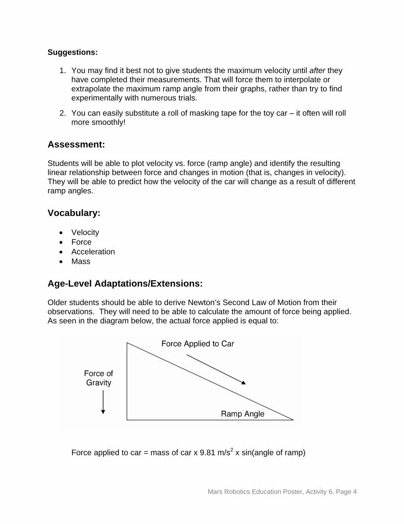
Older students should be able to derive Newton’s Second Law of Motion from their observations. They will need to be able to calculate the amount of force being applied. As seen in the diagram below, the actual force applied is equal to:
Force applied to car = mass of car x 9.81 m/s2 x sin(angle of ramp)
Mars Robotics Education Poster, Activity 6, Page 4
9.81 m/s2 is the acceleration due to gravity (how fast gravity makes things fall) at the Earth’s surface. It would be useful to have your students derive this for themselves as well. On Mars, the acceleration due to gravity is only 3.71 m/s2. Ask your students: how would this change the results? (Essentially, the rover would be able to travel down a steeper slope because it will not fall as fast down the slope.)
Younger students need not actually graph the data to be able to see the relationship that we want to get across to them. They can easily obtain the qualitative grasp of the concept by doing the experiment without taking measurements.
“High-Tech” Adaptations/Extensions:
Instead of using the inclined plane to provide a force, students can build motorized cars with a variable-voltage motor. The more voltage that is supplied to the motor, the more force the motor will apply. The concept of “calibrating” a robot’s motors will become very important in “high-tech” extensions of later activities.
Appendix:
For reference, here is a brief summary of Newton’s Laws of Motion:
Newton’s First Law (also called the “Law of Inertia”) says:
“An object at rest will remain at rest, or an object in motion will continue in motion at the same speed and direction, unless acted upon by an outside force.”
Newton’s Second Law says:
“The acceleration given to an object is directly proportional to the force applied to it.”
In simple terms, Newton’s First Law says that if you push on something, it will keep moving in a straight line unless you push it again in some other way. Newton’s Second Law says that you have to push harder if the object is heavy (has a large mass) or if you want it to increase its velocity quickly (give it a high acceleration). We can actually calculate the force needed to accelerate an object using the formula:
F = m x a (force = mass x acceleration)
In this formula, “m” is the mass of the object and “a” is the acceleration you want to give it. In this activity, students will be studying the acceleration that results from a certain force being applied to the cars, so you will probably want to write the formula as:
a = F (acceleration = force ÷ mass) m
Mars Robotics Education Poster, Activity 6, Page 5
This activity is designed to prepare students to begin to analyze simple machines, which form the basis for all robotic designs
NOTE: In the interest of completeness, Newton’s Third Law states, “For every action there is an equal and opposite reaction.” This law is the fundamental principle that makes rockets work! While it is not discussed in this activity, it might be a good time to include a demonstration of Newton’s Third Law using a balloon (just blow it up and let it go!). NASA made extensive use of Newton’s Third Law in getting to Mars in the first place: the booster used to launch a spacecraft and the onboard thrusters used during the cruise to Mars are direct applications of the Third Law.
Credits:
Keith Watt, M.A., M.S. ASU Mars Education Program Mars Space Flight FacilityArizona State [email protected]
(480) 965-1788
Mars Robotics Education Poster, Activity 6, Page 6

Name _____________________
Descent Into Endurance Crater: Data Log
Follow these steps to fill out your Data Log:
1. Measure the angle of the crater wall with a protractor and record it in the box.
2. Release the car (your model rover) from the top of the incline. Start the clock when the front wheels of the car pass the bottom of the incline.
3. Stop the clock with the front wheels of the car have traveled one meter. Record the time in the second box.
4. Record the final velocity (distance traveled – 1 meter – divided by time elapsed) in the last box.
5. Plot the crater wall angle versus the final velocity on the graph paper.
6. Extend your plot from 0 degrees to 90 degrees and use this graph to predict the maximum crater wall angle your Opportunity model can travel down without exceeding its maximum safe speed (given by your teacher).
Wall Angle (degrees)
Time Elapsed (sec) Final Velocity (m/s) Observations
Mars Robotics Education Poster, Activity 6, Page 7
Name _____________________
Descent into Endurance Crater: Student Questions
1. How do forces affect the motion of an object?
2. How will the velocity of the car change as the angle of the ramp increases? At what angle will the car feel the most force? At what angle will the car feel the least force?
3. At what angle will the rover model exceed its maximum safe speed of one meter per second? Estimate this angle using the graph you created and include this graph with your answer.
Mars Robotics Education Poster, Activity 6, Page 8
ACTIVITY #6: Teacher Answer Key
Note: These answers just give the key concepts you should look for in the student’s answer. The level of sophistication in the answers should be appropriate for the level of your students. They do not need to exactly match what the student says!
1. How do forces affect the motion of an object?
A force will always change the motion of an object in some way. It could speed up the object, slow it down, or change its direction. All of these examples are changes in velocity; a change in velocity is called an acceleration (or a deceleration if the velocity decreases). The heavier the object is, the more force is required to change its motion. Similarly, more force is required to make a larger change in the velocity.
2. How will the velocity of the car change as the angle of the ramp increases? At what angle will the car feel the most force along the ramp? At what angle will the car feel the least force along the ramp?
As the ramp angle increases, the downward force on the car (the part of gravity that is not deflected by the ramp) will increase. A greater force means a greater acceleration, so the final velocity of the car will be greater. The car will feel the most force along the ramp when it is vertical (90 degrees). The car will feel the least force along the ramp when it is horizontal.
3. At what angle will the rover model exceed its maximum safe speed of one meter per second? Estimate this angle using the graph you created and include this graph with your answer.
The actual answer here will vary depending upon the materials that you use to do the experiment, but using the graph, your students should be able to predict the angle which will yield a velocity of one meter per second at the bottom of the crater wall. Use their graphs to verify their answers.
Mars Robotics Education Poster, Activity 6, Page 9
MARS ROBOTICS EDUCATION POSTER http://mars.jpl.nasa.gov/classroom
Activity #7: Mars Rover and Lander Robotic Arms
Grade Levels: 5 -12 Time Frame: 30 – 45 minutes
Background:
When we send a spacecraft to the surface of Mars, we often want to interact closely with the martian surface or with the rocks we find there. The Viking 1 and Viking 2 landers sent to Mars in the mid-1970s were each equipped with robotic arms that could dig into the soil and bring samples of it back into the spacecraft for analysis. Both Mars Exploration Rovers, Spirit and Opportunity, carried a robotic arm that could place instruments directly on the surface of rocks that the rover encountered. The Phoenix lander will also possess a robotic arm for examining samples near its landing site at the martian north pole. Each of these robotic arms is vital to the success of the mission. Each is also a form of a lever, one of the most common of the six simple machines.
Robotic spacecraft, just like humans, are not able to exert huge amounts of force on their surroundings. Mars robots in particular are extremely limited in this regard: some Mars spacecraft run entirely on the same amount of power used by a single 100-watt light bulb! In order to perform difficult tasks such as digging trenches in the martian soil or extending a heavy package of instruments (tools for analyzing the chemistry and other characteristics of the surrounding environment) close to an interesting rock, the spacecraft needs some way to multiply the amount of force it can apply to the job. All complex machines, like robots, are made up of collections of simple machines NASA’s robotic explorers at Mars are excellent examples of the way in which simple machines are combined to make a sophisticated robot. The wheels on the Mars Exploration Rovers are obvious examples of simple machines, but there are also gears and levers in many of their components, as well. Simple machines are the building blocks that allow us to explore the universe!
In this background section, we explain the simple math that governs all simple machines (including levers), but we will first summarize the important concepts right up front:
•
.
The work performed to complete a particular task (force x distance) is always the same, no matter what.
Mars Robotics Education Poster, Activity 7, Page 1
• Machines help us by either reducing the amount of force we must apply (by applying a smaller force over a longer distance), or by changing the direction of the force we must apply to something more convenient.
• Mechanical advantage is a measure of how much the machine helps us do the task at hand.
You can perform this activity knowing only these facts, but read on if you want to learn why these facts are true!
Many students (and adults!) use the term “work” to mean “expenditure of effort,” but the precise definition of work is a force that is exerted over a distance. You can push against a wall with tremendous force, but if the wall doesn’t move, you haven’t done any work (no matter how sweaty you may be afterwards)! Mathematically, work is defined as:
Work = Force Applied x Distance
An important concept to understand when working with simple machines is that they do not reduce the work humans must do to perform the task! What they do is allow a smaller force (one the human can easily exert) to be applied over a greater distance. The work is the same, but the effort expended is a lot less. This outcome is the essence of the concept of mechanical advantage. Simply put, mechanical advantage is how much the machine is multiplying the amount of force you can apply to the task. If a machine has a mechanical advantage of 2.0, you get double the force out that you put in, but you have to apply that force over twice the distance you would without machine! Mathematically, mechanical advantage is defined as:
Mechanical Advantage = force required without machine force required with machine
Measuring the amount of force applied by a human being is a bit difficult to do (though you can substitute weights instead of having the students push and pull on the machines). It’s actually a lot easier to measure the distance over which you have to apply the force. Because force and distance are inversely (oppositely) related, we can also write the mechanical advantage as:
Mechanical Advantage = distance required with machine distance required without machine
You will often find that this definition is usually much easier to use with students, since it is more readily measured.
So how does all this work, then? Suppose we have a pulley with a mechanical advantage of 2.0 and we want to lift a 50-pound block a distance of 2 meters. Using the pulley, we would have to pull the rope a distance of 4 meters (twice the distance). How
Mars Robotics Education Poster, Activity 7, Page 2

does this help us? Remember that the work done is always the same. Since we are pulling the rope twice as far, we only have to use half as much force! So, instead of applying 50 pounds of force over 2 meters, we only have to apply 25 pounds of force over 4 meters. Much easier!
Some simple machines have a mechanical advantage of 1.0; that is, they don’t reduce the force you need to exert at all. Why would we want to use them then? Simple machines can also make work more convenient by changing the direction of the force to be applied. For example, if you wanted to lift that 50-pound block 2 meters in the air without a machine, you’ve got no choice but to climb up on a 2-meter-high platform and haul it straight up. Instead, you could throw the rope over a peg mounted 2 meters above the ground. You could then pull down on the rope from the ground and raise the block to the height you need. You apply the same force, but now you can pull down on the rope instead of lifting it up, which is much more convenient.
In summary, again, here’s what you should remember about simple machines:
• The work done (force x distance) is always the same, no matter what.
• Machines help us by either reducing the amount of force we must apply (by applying a smaller force over a longer distance), or by changing the direction of the force we must apply to something more convenient.
• Mechanical advantage is a measure of how much the machine helps do the task.
Learning Goals:
Students will learn how forces are applied using a lever and will demonstrate an understanding of how machines can use the concept of mechanical advantage to decrease the amount of effort humans are required to exert to perform a task.
Materials Needed (per team of 4 students):
• Meter stick (to use as a lever) • ~Ten-centimeter wooden wedge (to use as a fulcrum) • Weights • Balance to measure weights (if weights are unlabeled) • Tape measure or second meter stick for distance measurements • Masking tape or cloth tape • Graph paper • Robotic Arm Data Log (p. 7)
Mars Robotics Education Poster, Activity 7, Page 3

Optional Materials:
• Plastic building bricks or other building kits • Electric motors
National Science Education Standards:
Content Standard A: Use Mathematics in All Aspects of Scientific Inquiry Content Standard B: Forces and Motion
National Council of Mathematics Teachers Principles and Standards:
Numbers and Operations: Use ratios and proportions to represent quantitative data
Data Analysis and Probability: Appropriate graphical representations of data
Measurement: Select and apply techniques and tools to make accurate calculations of length, area, volume, and angle measures to appropriate levels of precision
Procedure:
1. Attach a known weight to one end of the lever (the meter stick or some other lever). It is a good idea to secure it to the end of the lever with masking tape (cloth tape works even better) to make sure that the weight does not fall off.
2. Place the fulcrum exactly halfway along the stick (500 centimeters).
3. Have students add weights to the free end until the stick moves, raising the fixed weight. (It may be necessary to tape the weights to the free end to keep them from falling off.) This configuration represents a machine with a mechanical advantage of 1.0 – it neither helps the students lift the weight, nor makes it harder, but it does change the direction in which the force must be applied (down instead of up).
4. Have the students measure the length of the free end (from the free end to the fulcrum, or 500 centimeters in this case); the distance the fixed weight is lifted; and, the distance the free weight is lowered. Record these measurements, along with the weight required to move the fixed weight, on the data log.
5. Students should move the fulcrum forward (towards the fixed weight) and repeat steps 4 - 5. Repeat this process, making several measurements as the fulcrum is moved closer to the fixed weight.
Mars Robotics Education Poster, Activity 7, Page 4
6. Return the fulcrum to the center and repeat the process above, but this time move the fulcrum away from the fixed weight.
7. Plot the results on the graph paper, labeling one axis as distance moved and the other as weight applied.
Discuss with students what the graph means. The graph is linear, which means that there is a direct, simple relationship between the amount of force that must be applied to lift the weight and the distance that force must be exerted. Discuss with your students where they would place the fulcrum for a robotic arm intended to dig into the martian soil.
Assessment:
Students should submit their Data Logs and graphs to demonstrate that they understand the concept of mechanical advantage from simple machines.
Vocabulary:
• Simple machine • Lever • Work • Mechanical Advantage • Fulcrum
Age-Level Adaptations/Extensions:
It is not necessary for the younger students to perform all the measurements and plot all the data. What is important is that they gain a qualitative, intuitive grasp of how simple machines can reduce the force that they must apply to lift the weight. Because precise numbers are not required in this case, consider using a fairly heavy weight (5-10 pounds) and have them push down on the lever itself, moving the fulcrum as described. You could do this experiment on the see-saw and use your students as the weights!
For older students, they should be able to directly calculate the work done (force x distance) and the mechanical advantage of the lever with the fulcrum in the different positions. Consider having them do this experiment with other simple machines (gears, pulleys, etc.) – they will have to use their knowledge of machines to recognize and analyze where the force is being applied and over what distance the weight is being moved!
Mars Robotics Education Poster, Activity 7, Page 5
“High-Tech” Adaptations/Extensions:
Many building kits are often nothing more than collections of simple machines. Consider using a motor with a fixed power (and therefore force) output. How can the students use simple machines to increase the effective force that this motor can provide? What is the largest weight the motor can lift on its own? How large a weight can it lift using a simple machine?
Credits:
Keith Watt, M.A., M.S. ASU Mars Education Program Mars Space Flight FacilityArizona State [email protected] (480) 965-1788
Mars Robotics Education Poster, Activity 7, Page 6
Name: _________________________
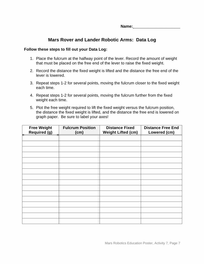
Mars Rover and Lander Robotic Arms: Data Log
Follow these steps to fill out your Data Log:
1. Place the fulcrum at the halfway point of the lever. Record the amount of weight that must be placed on the free end of the lever to raise the fixed weight.
2. Record the distance the fixed weight is lifted and the distance the free end of the lever is lowered.
3. Repeat steps 1-2 for several points, moving the fulcrum closer to the fixed weight each time.
4. Repeat steps 1-2 for several points, moving the fulcrum further from the fixed weight each time.
5. Plot the free weight required to lift the fixed weight versus the fulcrum position, the distance the fixed weight is lifted, and the distance the free end is lowered on graph paper. Be sure to label your axes!
Free Weight Required (g)
Fulcrum Position (cm)
Distance Fixed Weight Lifted (cm)
Distance Free End Lowered (cm)
Mars Robotics Education Poster, Activity 7, Page 7
MARS ROBOTICS EDUCATION POSTER http://mars.jpl.nasa.gov/classroom
Activity #8: Rover Races
Grade Levels: 5 - 12 Time Frame: 30 – 45 minutes
Background:
In this activity, students will program a human "rover" to navigate safely across a simulated martian landscape, retrieve a "Mars rock,” and return it safely to its "lander.”
Tele-operation (controlling a robot from a distance) is no easy task. Rovers that are operating on another planet cannot be driven in a real-time “joystick mode” because the time required for a signal to travel from the Earth to another planet is so great. Although newer rovers, such as the Mars Exploration Rovers, have quite a bit more capability to operate independently, they still fundamentally rely on command sets that have been created on Earth and uploaded to them.
The Mars Exploration Rovers were not designed to operate alone. Two orbiting spacecraft, Mars Global Surveyor and Mars Odyssey, continually provide orbital surveillance and communications for the rover. The spacecraft at Mars (orbiters and landers) must work together to provide the Earth-based controllers with the information they need to assure the success of the mission.
In this activity, your students will use all of these aspects to carry out a similar mission. The difficulties they will face and the resolution of those difficulties will be surprisingly like the real thing!
Learning Goals:
Students will apply their understanding of robotic programming to simulate a rover that must race other rovers across the Martian surface.
Mars Robotics Education Poster, Activity 8, Page 1
Materials Needed (per team of 4 students):
• Index cards (~50 per team, but have extras in case they are needed) • Obstacles (such as construction paper squares so the students won’t trip over
them when blindfolded) • Small Rock (~1 inch) • Stopwatch • Programming worksheet (p. 5)
Optional Materials:
• Blindfold • Video camera
National Science Education Standards
Content Standard E: Abilities of Technological Design
Procedure:
The task to be achieved with this activity is for the rover to move from its “lander” (starting point), navigate an obstacle course that represents a “martian terrain,” pick up a rock sample, and return it to the lander. All instructions must be “pre-programmed” on index cards prior to execution. The teacher will serve as the official timekeeper for the race.
Allow one student on each team to represent an “orbiter” in orbit around Mars. This student is allowed to get an “orbital view” of the obstacle course terrain by walking around the perimeter of the terrain and making whatever notes he or she wishes. Optionally, the student could use a video camera to beam a real-time image back to the rest of his or her team.
Inform the students that their mission is to navigate the rover from the starting point (the “lander”), to a rock sample, and back to the starting point. The rover should pick up the sample and return it to the “lander.”
Instruct the students to break that task into its specific sub-tasks, specifying each movement that must be performed in order to accomplish that task.
The students should write down each step on a separate index card. The rover will follow this “program.” Students should be given the freedom to decide the format of the commands they will issue. Their format represents the “operating system” or “programming language” of the rover.
Mars Robotics Education Poster, Activity 8, Page 2

Students should choose one member of their team to play the role of the rover’s "processor" and one student to play the role of the “rover” itself (its sensors and actuators).
The processor reads each card in order to the student playing the role of "rover.” The rover must follow the tasks exactly, no matter what the consequences.
The students should test their program on “Earth” (away from the actual terrain), including any calibrations of step size, before trying it out on the surface of “Mars.”
If the rover is unsuccessful in performing its tests on Earth, the student "programmers" should "debug" their program, modifying the index cards as appropriate, and try again.
The students are given one chance on the terrain. The “orbiter” student should report the success of the rover and make notes on what went right and what went wrong. If the rover becomes “stuck on” (touches) an obstacle, the rover can go no further in its commands. The “orbiter” may relay a new set of instructions from the Earth-based programmers to the rover to address the difficulty. The stopwatch is not stopped during this time!
The team that accomplishes the mission in the least amount of time is the winner!
For an even more accurate simulation of how a real rover works, the "rover" student should be blindfolded. Only when a "program card" calls for the rover’s "sensors" (the student’s eyes) to be used can the student remove the blindfold. One issue your students are going to run into right away is that of calibration: How big is one “step”? Let them discover this on their own if possible, but mention the concept to them if they don’t think of it themselves. Calibration of actuators is an extremely important part of building any robot!
Assessment:
Students should present to the teacher the attached “programming sheet,” which contains the final instructions for the mission, and should demonstrate on the “terrain” that the instructions will enable the student “rover” to fulfill that task. Students should be debriefed about what worked and what didn’t work with their mission.
Vocabulary:
• Processor • Program
Mars Robotics Education Poster, Activity 8, Page 3
Age-Level Adaptations/Extensions:
For the youngest students, you can use colored blocks or pictures to represent specific rover “commands” or tasks. The students can then organize the blocks or pictures to achieve their task.
Older students should be given (or create themselves) a diagram of the terrain (taken by an “orbital camera”) and come up with an accurate calibration for their rover. They should be tasked with converting the scale of the diagram to real-world measurements and then converting those real-world measurements into rover “steps.”
“High-Tech” Adaptations/Extensions:
Use a commercial robotics kit and the included programming software to program an actual robot to accomplish the mission!
Credits:
Sheri Klug, M.S. ASU Mars Education Program
Adapted by:
Keith Watt, M.A., M.S. ASU Mars Education Program Mars Space Flight FacilityArizona State [email protected]
(480) 965-1788
Mars Robotics Education Poster, Activity 8, Page 4
Name: ________________________________
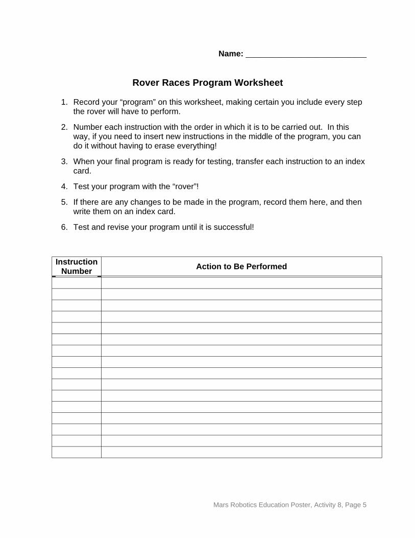
Rover Races Program Worksheet
1. Record your “program” on this worksheet, making certain you include every step the rover will have to perform.
2. Number each instruction with the order in which it is to be carried out. In this way, if you need to insert new instructions in the middle of the program, you can do it without having to erase everything!
3. When your final program is ready for testing, transfer each instruction to an index card.
4. Test your program with the “rover”!
5. If there are any changes to be made in the program, record them here, and then write them on an index card.
6. Test and revise your program until it is successful!
Instruction Number Action to Be Performed
Mars Robotics Education Poster, Activity 8, Page 5
MARS ROBOTICS EDUCATION POSTER http://mars.jpl.nasa.gov/classroom
Activity #9: Bringing Mars Home: Get it on board!
Grade Levels: 5 -12 Time Frame: 2 – 3 45-minute class sessions*
*or construction time outside of class
Background:
In the coming decades, NASA hopes to build a robot that can travel to Mars, pick up a rock from the surface (called a “sample”), and bring it back to Earth. In order to achieve this goal, one of the fundamental goals to accomplish is designing a way to get the rock from the surface into the sample return canister for shipment back to Earth. While the sample-return robot will use its own internal power source, students will be challenged to use only the wind produced by a small box fan as their sole source of power. You could more accurately model the actual Mars spacecraft by using electric motors and solar panels, if you desire.
In this activity, students are presented with a straightforward, but surprisingly complex task: create a wind-powered machine that will produce the maximum power output possible to lift a “Mars rock” from the surface to the spacecraft. Power is defined as the work performed divided by the time required to perform it (work, as the students have learned in previous activities, is the force applied multiplied by the distance over which it is applied). Students can approach the problem from a number of different directions: some will want to lift a small weight very quickly, others will want to move a larger weight a bit more slowly. The distance in both cases will be fixed. In the end, it is only the final number – the power – that will determine the winner!
The materials used for this activity can be as common or exotic as you desire. Remember, the only source of energy for the machine is a small box fan. The lifting machine can easily be constructed out of household materials such as dowels, craft sticks, and cardboard, but adding pulleys and gears (which provide mechanical advantage; see Mars Robotics Poster Activity #7: Rover and Lander Robotic Arms) can make the contest even more of a challenge!
Mars Robotics Education Poster, Activity 9, Page 1
Fun Fact:
Did you know that there is wind on Mars? The wind velocities on the surface are very high, but because the atmosphere is so thin (Mars has about 1% the atmosphere of Earth), the force exerted by that wind is quite small. Ask your students how they would redesign their machine to capture the wind on Mars!
Learning Goals:
Students will put their knowledge of the design process into practice by designing a wind-powered robot that has the maximum power output (work divided by time).
Materials Needed (per team of 4 students):
• Craft or popsicle sticks • Stiff cardboard • White glue • String • Weights (or rocks) • Balance (if weights are unlabeled) • Stopwatch • Dowel • Box fan (one for entire class) • “Bring Mars Home” Data Sheet (p. 5)
Optional Materials:
• Gears • Pulleys • Calculators
National Science Education Standards
Content Standard B: Forces and Motion Content Standard E: Abilities of Technological Design
Procedure:
Begin the activity by reviewing the concept of work (force applied over a distance) that the students have learned in previous activities. If your students have not done these activities, or are not familiar with the concept, you may want to briefly introduce it. The two key concepts are that a force must be applied and the object receiving the force must move. The force multiplied by the distance is the work.
Mars Robotics Education Poster, Activity 9, Page 2
The concept of power builds upon the definition of work. Power is simply work done over time. The more work one does in a shorter period of time, the greater the power that was used. Students will gain direct experience with the definition of power in this activity.
Present the task to the students: build a lifting robot that will produce the greatest power output, by lifting a “Mars rock” off the ground to the height of their “spacecraft.” (Note that while the students are normally able to set the height of their “spacecraft” to any height they desire, you can simplify the activity by specifying a height – one meter works well – and thus reduce the number of variables with which the students have to experiment.) Point out that there a number of ways they could achieve this task. They could lift a small weight very quickly, a very large weight slowly, or some combination of these extremes. Give the students the materials and instruct them to begin brainstorming about what key elements will be needed to solve their problem.
Students will need to consider the following aspects in their design:
• How high will we need to raise the weights (work is force times distance)? • How much weight will we lift (work is force times distance)? • How fast will we lift the weight (power is work divided by time)? • What kind of support structure will we use for the robot? • How will we capture the wind from the fan? • How will we use it to raise the weight? • What will we use to carry the weight?
These are just examples; your students may come up with more key elements on their own. Note that the lifting machine must be entirely wind-powered – the robot cannot be physically connected to the fan in any way.
When all the designs are complete (the students should have tested and revised the various components as they were building them, but that is the focus of other activities), have each student team bring their robot to the “official test area.” Weigh the objects being lifted and measure the height that they are to be lifted. When the team is ready, turn on the fan and start the stopwatch! The students should calculate the power output of their robot using the following formula (it will be helpful to write these formulae on the blackboard, explaining what each part of them represent):
Force (newtons) = mass of object (kg) x 9.81 m/s2
Power (watts) = force (newtons) x distance raised (meters) time to lift (seconds)
9.81 m/s2 is the acceleration due to gravity on Earth. Feel free to substitute the acceleration due to gravity on Mars (3.71 m/s2) to see how the results would change! Record the team’s power output on a “scoreboard” such as the blackboard. The team
Mars Robotics Education Poster, Activity 9, Page 3
with the highest power output is the winner! This activity makes an excellent school- or district-wide competition!
Assessment:
Students should be able to calculate the force, work, and power of their robot and discuss how they arrived at their design.
Vocabulary:
• Work • Power • Newtons • Watts
Age-Level Adaptations/Extensions:
It may be wise to reduce the number of variables that younger students have to deal with in this activity. For example, you may want to set both the height and the mass to be lifted, allowing the students to focus exclusively on the robot itself.
Older students can be encouraged to start testing individual portions of the design to maximize the output of each stage. This task is dealt with specifically in Activity #4, but it is worth addressing here as well.
“High-Tech” Adaptations/Extensions:
Gears and pulleys will add mechanical advantage to the robot and enable your students to experiment with the effects of these simple machines. Electric motors could be used in place of the wind generator, allowing your students to compare the power output of different motors and batteries.
Credits:
Keith Watt, M.A., M.S. ASU Mars Education Program Mars Space Flight FacilityArizona State [email protected]
(480) 965-1788
Mars Robotics Education Poster, Activity 9, Page 4
_
_
_
_______________
_____________
_
_
_
_
_________________
_____________________________________________________________________
_____________________________________________________________________
_____________________________________________________________________
_______________________________________________________
_________________________________________________________
_____________________________________________________________________
_____________________________________________________________________
_____________________________________________________________________
_____________________________________________________________________
_____________________________________________________
Name: _______________________________
Bring Mars Home! Data Log
Use this sheet to record your observations during your test, evaluation, and revision process. You should think about and answer the following questions as you conduct your tests:
• How high will we need to raise the weights (work is force times distance)? • How much weight will we lift (work is force times distance)? • How fast will we lift the weight (power is work divided by time)? • What kind of support structure will we use for the robot? • How will we capture the wind from the fan? • How will we use it to raise the weight? • What will we use to carry the weight?
Remember, the winner will be the team whose robot can produce the greatest power output. Calculate your robot’s power using these equations:
Force (newtons) = mass of object (kg) x 9.81 m/s2
Power (watts) = force (newtons) x distance raised (meters) time to lift (seconds)
Mars Robotics Education Poster, Activity 9, Page 5
MARS ROBOTICS EDUCATION POSTER http://mars.jpl.nasa.gov/classroom
Activity #10: Bringing Mars Home: Mars Launch Platform
Grade Levels: 5 -12 Time Frame: 45 – 60 minutes
Background:
Bringing a sample rock into a return spacecraft is only the first step in returning a Mars rock to Earth. The return spacecraft will also need a platform for its launch from the martian surface. The launch platform will need to meet two requirements: first, it must be able to support as large a mass as possible (to allow it to support the return spacecraft), and second, it must be as tall as possible (to prevent damaging equipment still on the surface). The gravitational potential energy is defined as the energy stored in an object due to the fact that it has been lifted off of the ground. This potential energy can be easily converted into kinetic energy (energy of motion) by simply dropping the object! Mathematically, the gravitational potential energy of an object can be found from:
Potential Energy = m x h x g
= mass of object (kg) x height of object (meters) x acceleration of gravity (9.81 m/sec2 on Earth, 3.71 m/sec2 on Mars)
As you can see, the potential energy combines both of the requirements for the launch platform: mass and height. Therefore, your students will be tasked to build a platform that can give the spacecraft the greatest gravitational potential energy.
Completed designs almost never spring fully formed from their designers’ imaginations. Early prototype ideas are considered and are modified or rejected in favor of something new. As each version of the design is tested, evaluated, and revised, it gradually takes shape into its finished form. The result is a design that can be trusted to fulfill its goals when the final version is constructed. Often, it is too difficult or too expensive to perform this test, evaluation, and revision process on the entire design. Instead, engineers will often test smaller portions of the design, and only test the entire system when they are certain that the sub-systems are the right ones for the job.
Mars Robotics Education Poster, Activity 10, Page 1
In this activity, students will discover the test, evaluation, and revision process firsthand. Students will be given toothpicks and clay and will be asked to build a structure that can support the greatest gravitational potential energy (mass x height x acceleration due to gravity). Students are encouraged to try different forms of structures (cross beams, suspensions, triangles or other geometric shapes, etc.), testing each type to see which can support the most weight.
While there is a competitive nature to this activity, it is important that students get as many chances as they wish to experiment with different designs. In the interest of time (and to introduce the idea of testing small sub-systems instead of finished designs), students should be encouraged to test small, representative portions of a given type of structure before attempting to build the final tower. For example, students can explore how much weight a single triangular structural unit can support and compare that to a single structural unit of another type before constructing an entire platform for final testing. The goal is for students to experience the iterative nature of the engineering design process. They should feel free to make continual refinements to their design in order to increase its performance!
Learning Goals:
Students will learn how the test, evaluation, and revision process ensures that a finished design will meet its design goals and engineering constraints. Students will also learn how to define and calculate the gravitational potential energy of a body.
Materials Needed (per team of 4 students):
• Toothpicks (approximately 100-200 per team) • 2 sticks of firm modeling clay per team • Weights (rocks, clay, or batteries work well) • Balance (to measure weights) • Meter stick (to measure height) • Mars Launch Platform data log (p. 5)
Optional Materials:
• String
National Science Education Standards
Content Standard E: Abilities of Technological Design
Mars Robotics Education Poster, Activity 10, Page 2
Procedure:
Pass out the toothpicks, modeling clay, and weights to each team.
Inform the students that they are to design and build a launch platform that can support the greatest weight possible at the greatest height possible.
Introduce the concept of gravitational potential energy and demonstrate mathematically how this concept incorporates both design goals in a single number.
Ask the students to brainstorm (sketching on paper, if desired) what kinds of support structures they could use to build the platform. They should feel free to use their imagination to come up with any support structures they can devise – they shouldn’t feel restricted to the “traditional” types!
Caution the students that because of time constraints, they should test small, individual structural units, not the final design – they will be able to make more revisions in the same amount of time this way.
When the final structure is complete, it can be tested and revised as often as the students desire.
The platform that can support the greatest gravitational potential energy is the winner!
At your option, you can also give the students string so that they can experiment with suspension supports (similar to those used with suspension bridges like the Golden Gate Bridge in San Francisco) as well.
Assessment:
The students should demonstrate that they have experimented with a number of different designs by presenting their small prototype models before they construct and test the final platform. They should also calculate the gravitational potential energy given to the rock by their structure – remember, the structure that gives the rock the highest potential energy wins!
Vocabulary:
• Structure • Subsystem • Gravitational potential energy • Kinetic energy
Mars Robotics Education Poster, Activity 10, Page 3
Age-Level Adaptations/Extensions:
Younger students could build structures out of blocks or plastic building bricks instead toothpicks. These types of materials are much more easily manipulated.
Older students should be expected to produce more sophisticated designs and should be able to give a presentation detailing why they feel their design is the best for the task.
“High-Tech” Adaptations/Extensions:
Build a ramp that will allow a computerized rover to climb to the top of the platform safely! This adds a whole new dimension to the problem, as the moving rover will cause a moving stress on the structure.
Credits:
Keith Watt, M.A., M.S. ASU Mars Education Program Mars Space Flight FacilityArizona State [email protected]
(480) 965-1788
Mars Robotics Education Poster, Activity 10, Page 4
______________________________________________________________________
______________________________________________________________________
______________________________________________________________________
______________________________________________________________________
______________________________________________________________________
______________________________________________________________________
______________________________________________________________________
______________________________________________________________________
______________________________________________________________________
Name: ______________________________
Bringing Mars Home: Mars Launch Platform Data Log
Use this sheet to record your observations during your test, evaluation, and revision process. You should think about and answer the following questions as you conduct your tests:
• What type of structural units (triangles, squares, etc.) will support the most weight?
• Do we want to build a short and sturdy structure that support a heavy weight, or a tall structure that can only support a small weight, or some combination of the two?
• What data should we gather to prove that our structures will stand?
Remember, the winner will be the team with a structure that can give a rock the greatest gravitational potential energy. Use this formula to calculate the gravitational potential energy given by your structure:
Potential Energy = m x h x g
= mass of object (kg) x height of object (meters) x acceleration of gravity (9.81 m/sec2 on Earth, 3.71 m/sec2 on Mars)
Mars Robotics Education Poster, Activity 10, Page 5
MARS ROBOTICS EDUCATION POSTER http://mars.jpl.nasa.gov/classroom
Activity #11: Mars Mission Planning
Grade Levels: 5 - 12 Time Frame: 1–2 45-minute class periods
Background:
This activity represents the first part of the culmination of activities contained on the Mars Robotics Education Poster. Students are presented with the task of designing a robot that can complete a specific task on Mars: landing on a simulated surface, retrieving a rock sample, and returning it to "Earth.” Students should plan every aspect of the mission in detail, including a plan for how they will test and evaluate their design. Unlike Activity #8 (Rover Races), students are expected to construct a physical rover and launch system out of the materials made available to them.
Students should be expected to test individual subsystems of their robot, performing many of the tasks they have learned in previous activities. Only after each sub-system has been tested and found to meet its mission goal should the entire robot be brought together for "system integration testing.” Consider having your students write a formal "design specifications document" that summarizes their plan and their basic design. This document will then serve as a guide for the final activity that follows.
Mission planning is not an easy job. At first, your students will spend much of their time figuring out what systems they need (landing system, mobility system, etc.) and then how they can build those systems with the materials they’ve been provided. As the design begins to take shape and they begin their testing however, they should begin to think about what could go wrong and how they will deal with those eventualities! Encourage them to be creative in their solutions. Almost any solution is acceptable – if it works. Their propulsion could be provided by a well-aimed push, guidance could be provided by portable walls that ensure the rover will travel to its target. Their imaginations are the limit!
Mars Robotics Education Poster, Activity 11, Page 1

Learning Goals:
Students will be given a problem to be solved (design a Mars sample-return mission) and will use their knowledge of technology and robots to design an appropriate solution.
Materials Needed (per team of 4 students):
• Craft sticks, wood, cardboard, wheels, tape, glue, or any other common materials or recyclables you wish to provide your students.
• Student data log (p. 4)
Optional Materials:
• Motors and gears
National Science Education Standards
Content Standard E: Abilities of Technological Design Content Standard E: Understandings About Science and Technology
Procedure:
Distribute the materials you have made available to the teams, but inform them that they are not to begin construction at this point.
Present the task to the students: design a rover that can be:
• launched (i.e., they will need to design some way of launching the rover and hitting a target);
• land on the surface (i.e., withstand the stress of the launch and the fall back to the ground);
• travel to a location (either by motors, by being given a push, or some other means of propulsion);
• pick up a sample (strings attached to the rover that can be pulled is one way), • return that sample to the landing point; and, • launch it back to a target representing Earth.
Be sure to identify each phase of the mission individually so that your students are aware of each stage for which they must plan.
Students will not be allowed to set foot on the “terrain” area – all operations must be conducted from outside the terrain area (at the edge of the terrain or beyond).
Mars Robotics Education Poster, Activity 11, Page 2
Students should break the mission into tasks and devise a test plan for each subsystem that makes up the rover.
Students should begin testing the subsystems, and time permitting, present their test results to the class for evaluation. Optionally, have students write a formal “design specifications document.”
As you observe the students, encourage them to think about the concepts, methods, and techniques they have learned as part of this unit. Encourage them to “plan for the unplanned.”
Assessment:
Students should present to the teacher and the class their overall mission plan and the results of their preliminary testing, along with their data log.
Vocabulary:
• Design specifications document
Age-Level Adaptations/Extensions:
For younger students, you should limit the scope of the project to just one task, such as launching and hitting a target, or propelling the rover to the target site.
Older students could be given the opportunity to use model rockets that can carry a payload to simulate the launch and recovery phases of the mission. Extensive test results should be expected from this age group in any case. Optionally, assign a dollar cost to each part and give the students a budget!
“High-Tech” Adaptations/Extensions:
Conduct the mission using commercial robotics kits!
Credits:
Keith Watt, M.A., M.S. ASU Mars Education Program Mars Space Flight FacilityArizona State [email protected]
(480) 965-1788
Mars Robotics Education Poster, Activity 11, Page 3
______________________________________________________________________
______________________________________________________________________
______________________________________________________________________
______________________________________________________________________
______________________________________________________________________
______________________________________________________________________
______________________________________________________________________
______________________________________________________________________
______________________________________________________________________
______________________________________________________________________
______________________________________________________________________
______________________________________________________________________
______________________________________________________________________
______________________________________________________________________
______________________________________________________________________
______________________________________________________________________
______________________________________________________________________
______________________________________________________________________
Name: ______________________________
Planning for the Mars Mission Data Log
Use this sheet to record your observations during your design process. Be sure to identify each task involved in each phase of the mission along with your ideas for accomplishing that task. Use additional paper if necessary.
Mars Robotics Education Poster, Activity 11, Page 4
MARS ROBOTICS EDUCATION POSTER http://mars.jpl.nasa.gov/classroom
Activity #12: Bringing It All Together: The Mars Mission
Grade Levels: 5 - 12 Time Frame: 1-2 45-minute class period
Background:
In this activity, students will actually carry out the design they have created in Robotics Education Poster Activity #11 (Planning for the Mars Mission). The scope of this activity can be as simple or as complex as you desire (and have resources available). For example, your students could "return the sample to Earth" by building a lever-based "springboard" that propels the sample canister back to a predetermined spot that represents Earth or your students could construct an actual flying model rocket that carries its payload skyward and is expected to land within a given confined area. The “Procedures” section gives some suggested rules for the mission.
Regardless of the level of simulation, the students should still carry out their design, test, evaluation, and revision plans for each sub-system of their robotic explorer. This activity is a great deal of fun but will also serve to cement in their minds how robots are created and used to explore the Solar System!
Learning Goals:
Students will take the mission plan developed in the Mars Robotics Education Poster Activity #11 and actually construct their proposed robot. They will engage in the test, evaluation, and revision process planned in that activity and make adjustments as appropriate, culminating with the presentation of the design to their "customer" and a final “flight test” of the design.
Materials Needed (per team of 4 students):
• Craft sticks, wood, cardboard, wheels, tape, glue, or any other common materials or recyclables you wish to provide your students.
• Small rock
Mars Robotics Education Poster, Activity 12, Page 1
• Design specifications document from Robotics Education Poster Activity #11 (if created)
• Meter stick for measuring launch accuracy (how close the spacecraft landed to the target)
• Student data log (p. 4)
Optional Materials:
• Motors and gears
National Science Education Standards
Content Standard E: Abilities of Technological Design Content Standard E: Understandings About Science and Technology
Procedure:
Distribute the materials you have made available to the teams.
Allow the students to complete any last-minute testing on subsystems for their design.
Have the students construct their finished design. They are allowed to perform any last-minute “systems integration testing” that they desire, but may not move to the launch area until all testing is complete.
Designate a target that represents your students’ landing site. It can be in the terrain area or off of it, at your discretion.
For safety purposes, ensure that everyone remains well clear of the landing area.
Have each student launch their rover with whatever method they have devised (catapults, rubber bands, and ramps are common solutions). The rover should hit the landing site (or near it, at your option) for the students to continue to the next phase.
Move the students’ rover to the landing site (or, at your option, have the students begin from where the rover actually landed). The students must now get their rover within range to pick up the rock without allowing any part of their bodies to cross into the terrain area (ramps with or without guide walls, strings, etc. are all common solutions).
When the rover reaches the rock (they get additional opportunities to approach the rock only if they can somehow do so without crossing the edge of the terrain with their bodies), they should get the rock into whatever means of transport they have devised. (Scoops controlled by strings or extendable claws are common solutions.)
Mars Robotics Education Poster, Activity 12, Page 2
The students must then get the rover back to the landing site, again without any part of their bodies crossing the edge of the terrain.
Finally the launch sequence must be repeated, hitting a target that represents Earth. At least the rock must hit the target and it must not be damaged in any way. The students may devise carriers for the rock so that it is protected during the return journey.
This activity makes an excellent school-wide or district-wide competition!
Assessment:
Students should present to the teacher and the class their overall mission plan and the results of their preliminary testing.
Vocabulary:
• Systems integration
Age-Level Adaptations/Extensions:
As with Mars Robotics Education Poster Activity #11, for younger students, you should limit the scope of the project to just one task, such as launching and hitting a target, or propelling the rover to the target site.
Older students could be given the opportunity to use model rockets that can carry a payload to simulate the launch and recovery phases of the mission. The mission parameters can be made much more strict for this age group as well.
“High-Tech” Adaptations/Extensions:
Conduct the mission using commercial robotics kits!
Credits:
Keith Watt, M.A., M.S. ASU Mars Education Program Mars Space Flight FacilityArizona State [email protected]
(480) 965-1788
Mars Robotics Education Poster, Activity 12, Page 3
_
_
_
_
_
_
_
______________________
_
_
_
_
_
_
_______________
_____________
_____________________________________________________________________
_____________________________________________________________________
_____________________________________________________________________
_____________________________________________________________________
______________________________________________________________________
_____________________________________________________________________
_________________________________ ____________________________________
______________________________________________________________________
_____________________________________________________________________
________________________________________________
_____________________________________________________________________
_____________________________________________________________________
_____________________________________________________________________
_____________________________________________________________________
_____________________________________________________________________
_____________________________________________________________________
_______________________________________________________
_________________________________________________________
Name: ______________________________
Bringing It Together: the Mars Mission Data Log
Use this sheet to record your observations during the final test and evaluation of your mission. What changes did you have to make in your design? How did your design perform?
Mars Robotics Education Poster, Activity 12, Page 4