MANUFACTURING TECHNOLOGY - Iairwalkbooks.com/images/pdf/pdf_87_1.pdf · machines – Compression...
192
(Near All India Radio) 80, Karneeshwarar Koil Street, Mylapore, Chennai – 600 004. Ph.: 2466 1909, 94440 81904 Email: [email protected], [email protected] www.airwalkbooks.com, www.srbooks.org For III Semester B.E., Mechanical Engineering Students As per Latest Syllabus of Anna University - TN New Regulations 2017 With Short Questions & Answers and University Solved Papers MANUFACTURING TECHNOLOGY - I (Production Technology) Dr. S. Ramachandran, M.E., Ph.D., Professor - Mech Sathyabama Institute of Science and Technology Chennai - 119 Dr. S. Ramesh, B.E., M.Tech, Ph.D., FIE., LM-ASME., LM-PMA Professor / HOD Mechanical Engineering KCG College of Technology, Chennai - 97 Dr. G. Nallakumarasamy, B.E., M.Tech (IITM)., Ph,D., MISTE, MSAE., Professor & Head Mechanical Engineering Excel Engineering College, Namakkal - 637 303
Transcript of MANUFACTURING TECHNOLOGY - Iairwalkbooks.com/images/pdf/pdf_87_1.pdf · machines – Compression...

(Near All India Radio)
80, Karneeshwarar Koil Street,
Mylapore, Chennai – 600 004.
Ph.: 2466 1909, 94440 81904Email: [email protected],
www.airwalkbooks.com, www.srbooks.org
For III Semester B.E., Mechanical Engineering Students
As per Latest Syllabus of Anna University - TN
New Regulations 2017
With Short Questions & Answers and University Solved Papers
MANUFACTURING TECHNOLOGY - I(Production Technology)
Dr. S. Ramachandran, M.E., Ph.D.,
Professor - MechSathyabama Institute of Science and Technology
Chennai - 119
Dr. S. Ramesh, B.E., M.Tech, Ph.D.,FIE., LM-ASME., LM-PMA
Professor / HODMechanical Engineering
KCG College of Technology, Chennai - 97
Dr. G. Nallakumarasamy,B.E., M.Tech (IITM)., Ph,D., MISTE, MSAE.,
Professor & Head Mechanical Engineering
Excel Engineering College, Namakkal - 637 303

250/-
Fourth Edition: June 2018
978-93-88084-00-0
www.srbooks.orgwww.airwalkbooks.com

ME8351 MANUFACUTRING TECHNOLOGY - I L T P C3 0 0 3
UNIT I METAL CASTING PROCESSESSand Casting: Sand Mould – Type of patterns – Pattern Materials – Patternallowances – Moulding sand Properties and testing – Cores – Types andapplications – Moulding machines – Types and applications; Melting furnaces;Blast and Cupola Furnaces; Principle of special casting process; Shell –investment – Ceramic mould – Pressure die casting – Centrifugal Casting –CO2 process – Stir casting; Defects in Sand casting
UNIT II JOINING PROCESSESOperating principle, basic equipment, merits and applications of: Fusionwelding processes: Gas welding – Types – Flame characteristics; Manualmetal arc welding – Gas Tungsten arc welding – Gas metal arc welding –Submerged arc welding – Electro slag welding; Operating principle andapplications of: Resistance welding – Plasma arc welding – Thermit welding– Electron beam welding – Friction welding and Friction Stir Welding;Brazing and soldering; Weld defects: types, causes and cure.
UNIT III METAL FORMING PROCESSESHot working and cold working of metals – Forging processes – Open,Impression and closed die forging – forging operations. Rolling of metals –Types of Rolling – Flat strip rolling – shape rolling operations – Defects inrolled parts. Principle of rod and wire drawing – Tube drawing – Principlesof Extrusion – Types – Hot and Cold extrusion.
UNIT IV SHEET METAL PROCESSESSheet metal characteristics – shearing, bending and drawing operations – Stretchforming operations – Formability of sheet metal – Test methods – special formingprocesses – Working principle and applications – Hydro forming – Rubber padforming – Metal spinning– Introduction of Explosive forming, magnetic pulseforming, peen forming, Super plastic forming – Micro forming.
UNIT V MANUFACTURE OF PLASTIC COMPONENTSTypes and characteristics of plastics – Moulding of thermoplastics – workingprinciples and typical applications – injection moulding – Plunger and screwmachines – Compression moulding, Transfer Moulding – Typical industrialapplications – introduction to blow moulding – Rotational moulding – Filmblowing – Extrusion – Thermoforming – Bonding of Thermoplastics.

INDEXA
Additives and Fillers in Plastics5.5
Additives 1.14
Adhesiveness 1.20
Air-Acetylene Welding 2.36
Air Furnace or Reverberatory Furnace1.81
Anisotropy 4.4
Arc Welding (or) Manual Metal arcWelding (or) Shielded arc Arcwelding 2.5
Arc Welding Equipment 2.38
BBacking sand 1.17
Bench Moulding1.20
Bending operations 3.68
Bending 3.4
Binder 1.13
Blanking 4.6
Blast Furnace 1.72
Blow Moulding 5.14, 5.36
Blowholes 2.109
Bonding of Thermoplastics 5.60
Bottom gates 1.103
Branched polymers 5.2
Brazing 2.95
CCarbon arc Welding 2.45
Cast Iron 1.47
Casting 5.15
Centrifugal Casting 1.127
Centrifuge Casting 1.131
Ceramic Mould Casting 1.121
Cereal binder 1.56
Chemical dip brazing2.96
Clay Content Test 1.31
Closed Die Forging (or) Impression DieForging (or) Precision Coal dust1.14
Cohesiveness 1.19
Cold chamber die casting 1.125
Cold forming 5.70
Cold Working Of Metals 3.3
Cold Spinning 3.65
Cold Working Processes
Collapsibility 1.20
Combustion zone 1.77
Compression Moulding 5.14, 5.29
Continuous Casting 1.138
Convertor 1.87
Cope and drag pattern 1.41
Core sand 1.17, 1.55
Core Making 1.56
Cores 1.54
Corn flour and Dextrin 1.14
Cracking 2.105
Cross-linked polymers 5.3
Crucible Furnaces 1.89
Cupola Furnace 1.74
Cupping Test 4.26
Cutting off 4.8
DDeep drawing (or) Cupping 3.56
Defects in Sand Casting 1.146
Dextrin 1.56
Die materials 3.31
Die design features 3.30
Dielectric welding 5.65
Diffusion Welding 2.78
Dimensional inspection 1.156
Index I.1

Dip Soldering 2.100
Dip Brazing 2.96
Direct Arc furnace 1.92
Distortion (or) Camber allowance1.53
Distortion 2.106
Draft (or) Taper allowance 1.52
Draft Angles 3.29
Draw spike 1.25
Drawing 3.4
Drives for Extrusion 3.63
Drop Forging 3.19
Dry strength 1.19
Dry sand 1.16
Dry sand moulding 1.22
EElastomers 5.11
Electric Furnaces 1.92
Electric arc Welding Processes2.37
Electro Hydraulic Forming 4.31
Electro Slag Welding2.50
Electrode Standards 2.23
Electrodes 2.12
Electron Beam Welding 2.85
Elongation 4.3
Excessive Penetration2.109
Explosive Forming 4.38
Explosive Welding 2.76
Extrusion defects 3.63
Extrusion 5.51
FFacing sand 1.16
Filler materials 2.97
Filler Materials and Fluxes in Brazing2.97
Fillers 5.6
Film Blowing and Sheet Blowing5.46
Flame Cutting 2.90
Flames Characteristics 2.33
Flasks 1.27
Flat Strip Rolling 3.39
Floor Moulding 1.21
Flowability Test 1.33
Flowability (or) plasticity 1.19
Flux Material 2.98
Flux Cored Arc Welding (FCAW)2.54
Follow board pattern 1.43
Forge Welding 2.70
Forging 3.19
Forging Tests 3.27
Forging Processes 3.6
Forging under sticking condition3.19
Forging Defects 3.25
Forming Limit Diagram (FLD)4.27
Four High rolling mill 3.36
Friction Stir Welding (FSW)2.74
Friction Welding 2.72
Furnace (or) Forge brazing 2.96
Fusion bonding 5.67
GGaggers 1.27
Gas Welding Processes 2.24
Gas Welding 2.5
Gas welding equipments 2.28
Gas Tungsten Arc Welding (GTAW)(or) Tungsten Inert Gas Welding(TIG) 2.48
Gas Metal Arc Welding (GMAW) orMetal Inert Gas Welding (MIG)2.49
Gate cutter 1.26
Gate 1.103
Gated pattern 1.43
I.2 Manufacturing Technology I - www.airwalkbooks.com

Gating System 1.100
Grain Fineness Test (GFT) 1.31
Grain size 4.4
Green strength 1.19
Green sand 1.15
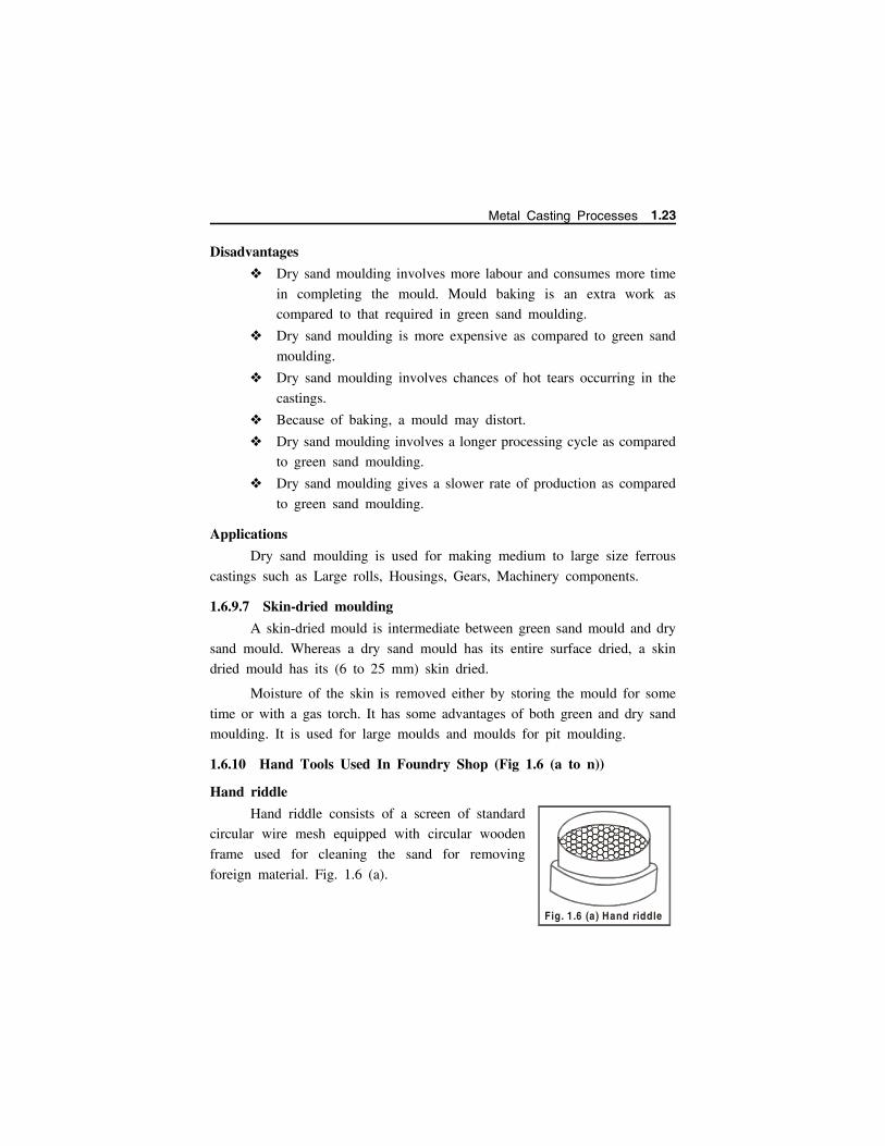
HHand riddle 1.23
Hand forging 3.13
Hard Soldering 2.100
Heat Affected Zone (HAZ) 2.11
High rolling mill 3.35
Horizontal core 1.64
Hot Box Core 1.64
Hot twist test 3.28
Hot gas welding5.66
Hot Rolling: Hot Working Of Metals3.2
Hot chamber die-casting 1.123
Hot Extrusion 3.59
Hot-platen welding 5.65
Hot Spinning 3.65
Hydro Mechanical Forming 4.31
Hydro Forming 4.29
Hydrostatic Extrusion3.61
IImpact extrusion (or) Cold Extrusion3.60
Induction brazing 2.96
Initiators 5.6
Injecting Moulding 5.17
Injection Blow Moulding 5.37
Inspection Method 1.156
Investment casting (Lost waxcasting) 1.118
JJolt-squeezer machine 1.69
Jolt machine 1.68
LLancing 4.9
Laser Beam Welding 2.83
Laser brazing and electron beambrazing 2.97
Lifters 1.25
Linear polymers 5.2
Liquid (Dye) Penetrant Test 1.163
Loam Moulding 1.21
Loam sand 1.16
Loose piece pattern 1.40
MMachine Moulding 1.21
Machining allowance 1.52
Magnetic Particle Inspection 1.160
Magnetic Pulse Forming 4.40
Mallet 1.24
Match plate pattern 1.41
Mechanical Fastening5.62
Mechanical Testing 1.157
Melting Furnaces 1.71
Melting zone 1.77
Metal Pattern 1.47
Metal Spinning 4.35
Micro-Forming 4.46
Modern Welding Processes 2.83
Modifiers 5.6
Moisture Content Test 1.30
Moisture / Water 1.13
Molasses 1.56
Molten metal bath process 2.97
Mould Hardness Test1.35
Moulding Sand Testing 1.29
Moulding Boxes 1.27
Moulding Machines 1.67
Index I.3

Multiple Roll Mill/Cluster roll mill3.37
NNetwork polymers 5.3
Nibbling 4.9
Notching 4.8
OOne piece (or) solid pattern 1.39
Open Hearth Furnace1.85
Open Die Forging (or) Smith DieForging (or) Flat-die ForgingOperations 3.10
Overlays 2.109
Oxy - Hydrogen Welding 2.36
Oxy-Fuel Gas Welding (OFW)2.24
Oxy – Acetylene Welding 2.25
PParting sand 1.17
Parting 4.8
Pattern Materials 1.46
Pattern 1.38
Pattern Allowances 1.51
Pattern draw machines 1.71
Peen Forming 4.42
Percussion Welding 2.67
Perforating 4.10
Permeability Test 1.36
Permeability 1.18
Piercing or Seamless Tubing3.48, 3.64
Piercing 4.7
Pit Furnace 1.89
Pit Moulding 1.21
Planetary rolling mill3.39
Plasma arc Welding 2.87
Plaster-mould casting 1.135
Plasticizers 5.5
Plunger moulding 5.34
Polymerisation Process 5.5
Polymers 5.1
Poor Weld Bead Appearance (Fig.2.51) 2.108
Porosity (Fig. 2.45) 2.104
Pot Transfer Moulding 5.33
Potting & Encapsulation 5.69
Power hammers 3.14
Power shearing 4.7
Power forging 3.14
Preheating zone 1.78
Preshaping 3.31
Press forging 3.20
Pressure Die Casting 1.123
Principle Of Rod And Wire Drawing3.52
Principles Of Extrusion 3.58
Protein binder 1.56
Punching4.7
RRammers 1.24
Rapping (or) Shake allowance1.53
Reaction-Injection Moulding (RIM)5.68
Reducing zone 1.77
Refractoriness 1.18
Refractoriness Test 1.32
Resistance Spot Welding 2.59
Resistance Welding 2.5
Resistance brazing 2.97
Ring rolling process: 3.46
Riser of Casting 1.106
Rod drawing process 3.54
Roll Forging 3.23
Rolling Of Metals 3.33
Rotary Melting Furnace 1.83
I.4 Manufacturing Technology I - www.airwalkbooks.com

Rotational Moulding 5.14, 5.42
Rubber Pad Forming 4.33
Runner 1.102
SSand Casting 1.5
Sand Mould 1.7
Sea coal and Pitch 1.14
Segmental (or) part pattern 1.45
Semi-Centrifugal Casting 1.130
Shape Rolling Operations 3.45
Shatter Index Test 1.34
Shaving 4.10
Shear Spinning 4.37
Shearing processes 3.66
Shearing 3.5
Sheet Metal Characteristics 4.2
Shell mould casting 1.114
Shell Core 1.63
Shovel 1.24
Shrinkage Cavity 2.109
Shrinkage allowance 1.51
Silica flour 1.15
Silica sand 1.12
Skeleton pattern 1.45
Skin-dried moulding 1.23
Slag Inclusion (Fig. 2.47) 2.106
Slicks 1.26
Slinging machines 1.70
Slitting 4.8
Slush-moulding 5.69
Smoothers 1.26
Soft Soldering 2.100
Solder Fluxes 2.102
Soldering 2.99
Solid State Welding 2.6
Solidification of Weld Metal2.10
Solvent Bonding5.62
Solvents 5.6
Spin Welding 5.62
Spirit level 1.26
Spray-gun 1.27
Spruce: 1.101
Sprue pin 1.24
Squeezer machine 1.68
Squeezing 3.5
Squeezing operations 3.69
Stack 1.78
Step gate 1.104
Stir casting 1.134
Strength Test 1.34
Stretch Blow Moulding (SBM)5.39
Strike off bar 1.24
Structural foam moulding 5.14
Stud welding 2.65
Submerged arc Welding 2.47
Sulphite binder 1.56
Super Plastic Forming 4.44
Surface Defects 3.48
Swab 1.26
Sweep pattern 1.44
System sand 1.17
TThermit Welding 2.62.81
Thermoforming 5.14, 5.56
Thermoplastics 5.7
Thermosetting resin 1.56
Thermosetting plastics 5.9
Thread rolling 3.47
Three-piece or multi- piece pattern1.42
Three High rolling mill 3.36
Index I.5

Torch brazing 2.96
Transfer Moulding 5.15, 5.32
Transfer moulding types 5.33
Trimming 4.10
Trowels 1.25
True Centrifugal Casting 1.128
Tube Drawing 3.55
Tube spinning 4.38
Two High reversible 3.35
Two piece (or) split pattern 1.39
Typical Shearing 4.4
UUltrasonic Welding 2.80
Ultrasonic Inspection 1.164
Undercutting and Overlapping (Fig.2.52) 2.108
Universal rolling mill 3.38
Unpressurized gating system:1.106
Upset forging (Heading) 3.21
Upsetting test 3.28
VVacuum casting 1.135
Vent rod 1.25
Vertical core 1.65
Vibration welding 5.67
Visual Inspection 1.156
WWave Soldering 2.100
Weld Defects - Types and Causes2.104
Weldability 2.6
Welding 2.42
Welding Terminology 2.7
Welding Positions 2.9
Well 1.76
White Metal 1.48
Wire drawing 3.54
Wood 1.46
Wood flour 1.15
YYield Point Elongation 4.3
I.6 Manufacturing Technology I - www.airwalkbooks.com
Table of ContentsUnit 1: METAL CASTING PROCESSES
1.1 Introduction to Solidification Process . . . . . . . . . . . . . . . . . . 1.1
1.2 Sand Casting . . . . . . . . . . . . . . . . . . . . . . . . . . . . . . . . . . . . . . 1.5
1.3 Sand Mould . . . . . . . . . . . . . . . . . . . . . . . . . . . . . . . . . . . . . . . 1.7
1.3.1 Features of Sand mould . . . . . . . . . . . . . . . . . . . . . . . 1.7
1.3.2 Desirable Mould Properties and Characteristics . . . 1.9
1.3.3 Steps/ Procedure for making sand mould . . . . . . . 1.9
1.4 Constituents of Moulding Sand. . . . . . . . . . . . . . . . . . . . . . 1.12
1.4.1 Silica sand . . . . . . . . . . . . . . . . . . . . . . . . . . . . . . . . . 1.12
1.4.2 Binder . . . . . . . . . . . . . . . . . . . . . . . . . . . . . . . . . . . . . 1.13
1.4.3 Moisture / Water . . . . . . . . . . . . . . . . . . . . . . . . . . . . 1.13
1.4.4 Additives . . . . . . . . . . . . . . . . . . . . . . . . . . . . . . . . . . . 1.14
1.4.4.1 Corn flour and Dextrin . . . . . . . . . . . . . . . . . . . . . . 1.14
1.4.4.2 Coal dust . . . . . . . . . . . . . . . . . . . . . . . . . . . . . . . . . . 1.14
1.4.4.3 Sea coal and Pitch . . . . . . . . . . . . . . . . . . . . . . . . . . 1.14
1.4.4.4 Wood flour . . . . . . . . . . . . . . . . . . . . . . . . . . . . . . . . . 1.15
1.4.4.5 Silica flour . . . . . . . . . . . . . . . . . . . . . . . . . . . . . . . . . 1.15
1.5 Types of Moulding Sands. . . . . . . . . . . . . . . . . . . . . . . . . . . 1.15
1.5.1 Green sand . . . . . . . . . . . . . . . . . . . . . . . . . . . . . . . . . 1.15
1.5.2 Dry sand . . . . . . . . . . . . . . . . . . . . . . . . . . . . . . . . . . . 1.16
1.5.3 Loam sand . . . . . . . . . . . . . . . . . . . . . . . . . . . . . . . . . 1.16
1.5.4 Facing sand . . . . . . . . . . . . . . . . . . . . . . . . . . . . . . . . 1.16
1.5.5 Backing sand . . . . . . . . . . . . . . . . . . . . . . . . . . . . . . . 1.17
1.5.6 System sand . . . . . . . . . . . . . . . . . . . . . . . . . . . . . . . . 1.17
1.5.7 Parting sand . . . . . . . . . . . . . . . . . . . . . . . . . . . . . . . . 1.17
1.5.8 Core sand . . . . . . . . . . . . . . . . . . . . . . . . . . . . . . . . . . 1.17
1.6 Moulding Sand Properties . . . . . . . . . . . . . . . . . . . . . . . . . . 1.18
Contents C.1
1.6.1 Refractoriness . . . . . . . . . . . . . . . . . . . . . . . . . . . . . . . 1.18
1.6.2 Permeability . . . . . . . . . . . . . . . . . . . . . . . . . . . . . . . . 1.18
1.6.3 Cohesiveness . . . . . . . . . . . . . . . . . . . . . . . . . . . . . . . . 1.19
1.6.4 Green strength . . . . . . . . . . . . . . . . . . . . . . . . . . . . . . 1.19
1.6.5 Dry strength . . . . . . . . . . . . . . . . . . . . . . . . . . . . . . . . 1.19
1.6.6 Flowability (or) plasticity . . . . . . . . . . . . . . . . . . . . . 1.19
1.6.7 Adhesiveness . . . . . . . . . . . . . . . . . . . . . . . . . . . . . . . . 1.20
1.6.8 Collapsibility . . . . . . . . . . . . . . . . . . . . . . . . . . . . . . . . 1.20
1.6.9 Classification of Moulding Processes. . . . . . . . . . . . 1.20
1.6.9.1 Bench Moulding. . . . . . . . . . . . . . . . . . . . . . . . . . . . . 1.20
1.6.9.2 Floor Moulding . . . . . . . . . . . . . . . . . . . . . . . . . . . . . 1.21
1.6.9.3 Pit Moulding . . . . . . . . . . . . . . . . . . . . . . . . . . . . . . . 1.21
1.6.9.4 Machine Moulding. . . . . . . . . . . . . . . . . . . . . . . . . . . 1.21
1.6.9.5 Loam Moulding . . . . . . . . . . . . . . . . . . . . . . . . . . . . . 1.21
1.6.9.6 Dry sand moulding . . . . . . . . . . . . . . . . . . . . . . . . . . 1.22
1.6.9.7 Skin-dried moulding . . . . . . . . . . . . . . . . . . . . . . . . . 1.23
1.6.10 Hand Tools Used In Foundry Shop . . . . . . . . . . . 1.23
1.7 Moulding Sand Testing. . . . . . . . . . . . . . . . . . . . . . . . . . . . . 1.29
1.7.1 Need for sand testing . . . . . . . . . . . . . . . . . . . . . . . . 1.29
1.7.2 Moisture Content Test . . . . . . . . . . . . . . . . . . . . . . . . 1.30
1.7.3 Clay Content Test . . . . . . . . . . . . . . . . . . . . . . . . . . . 1.31
1.7.4 Grain Fineness Test (GFT). . . . . . . . . . . . . . . . . . . . 1.31
1.7.5 Refractoriness Test . . . . . . . . . . . . . . . . . . . . . . . . . . . 1.32
1.7.6 Flowability Test . . . . . . . . . . . . . . . . . . . . . . . . . . . . . 1.33
1.7.7 Shatter Index Test . . . . . . . . . . . . . . . . . . . . . . . . . . . 1.34
1.7.8 Strength Test . . . . . . . . . . . . . . . . . . . . . . . . . . . . . . . 1.34
1.7.9 Mould Hardness Test . . . . . . . . . . . . . . . . . . . . . . . . 1.35
C.2 Manufacturing Technology I - www.airwalkbooks.com
1.7.10 Permeability Test . . . . . . . . . . . . . . . . . . . . . . . . . . . 1.36
1.8 Pattern . . . . . . . . . . . . . . . . . . . . . . . . . . . . . . . . . . . . . . . . . . 1.38
1.8.1 Functions of the Pattern . . . . . . . . . . . . . . . . . . . . . . 1.38
1.8.2 Types of Pattern . . . . . . . . . . . . . . . . . . . . . . . . . . . . . 1.39
1.8.3 Design Considerations for a good Pattern . . . . . . . 1.46
1.8.4 Pattern Materials . . . . . . . . . . . . . . . . . . . . . . . . . . . . 1.46
1.8.5 Selection of pattern material . . . . . . . . . . . . . . . . . . 1.50
1.8.6 Pattern Allowances. . . . . . . . . . . . . . . . . . . . . . . . . . . 1.51
(a) Shrinkage allowance . . . . . . . . . . . . . . . . . . . . . . . . . . . . 1.51
(b) Machining allowance . . . . . . . . . . . . . . . . . . . . . . . . . . . . 1.52
(c) Draft (or) Taper allowance . . . . . . . . . . . . . . . . . . . . . . . 1.52
(d) Rapping (or) Shake allowance . . . . . . . . . . . . . . . . . . . . 1.53
(e) Distortion (or) Camber allowance . . . . . . . . . . . . . . . . . 1.53
(f) Mould wall movement allowance . . . . . . . . . . . . . . . . . . 1.54
1.9 Cores . . . . . . . . . . . . . . . . . . . . . . . . . . . . . . . . . . . . . . . . . . . . 1.54
1.9.1 Functions (or) Objectives of core . . . . . . . . . . . . . . . 1.54
1.9.2 Core Sand . . . . . . . . . . . . . . . . . . . . . . . . . . . . . . . . . . 1.55
1.9.3 Considerations in Selecting Core Sand. . . . . . . . . . 1.55
1.9.4 Binders for core sand . . . . . . . . . . . . . . . . . . . . . . . . 1.55
1.9.5 Core Making . . . . . . . . . . . . . . . . . . . . . . . . . . . . . . . . 1.56
1.9.6 Types of Cores and Applications . . . . . . . . . . . . . . . 1.62
1.10 Moulding Machines . . . . . . . . . . . . . . . . . . . . . . . . . . . . . . . 1.67
1.10.1 Types and Applications of Moulding Machines. . 1.67
(a) Squeezer machine . . . . . . . . . . . . . . . . . . . . . . . . . . . . . . 1.68
(b) Jolt machine . . . . . . . . . . . . . . . . . . . . . . . . . . . . . . . . . . . 1.68
(c) Jolt-squeezer machine . . . . . . . . . . . . . . . . . . . . . . . . . . . 1.69
(d) Slinging machines . . . . . . . . . . . . . . . . . . . . . . . . . . . . . . 1.70
Contents C.3

(e) Pattern draw machines. . . . . . . . . . . . . . . . . . . . . . . . . . 1.71
1.11 Melting Furnaces . . . . . . . . . . . . . . . . . . . . . . . . . . . . . . . . . 1.71
1.11.1 Factors responsible for the selection of furnace . . 1.71
1.11.2 Types of Furnaces . . . . . . . . . . . . . . . . . . . . . . . . . . 1.72
1.11.3 Blast Furnace . . . . . . . . . . . . . . . . . . . . . . . . . . . . . . 1.72
1.11.4 Cupola Furnace . . . . . . . . . . . . . . . . . . . . . . . . . . . . 1.74
1.11.5 Air Furnace or Reverberatory Furnace . . . . . . . . . 1.81
1.11.6 Rotary Melting Furnace . . . . . . . . . . . . . . . . . . . . . 1.83
1.11.7 Open Hearth Furnace . . . . . . . . . . . . . . . . . . . . . . . 1.85
1.11.8 Convertor . . . . . . . . . . . . . . . . . . . . . . . . . . . . . . . . . . 1.87
1.11.9 Pit Furnace . . . . . . . . . . . . . . . . . . . . . . . . . . . . . . . . 1.89
1.11.10 Crucible Furnaces . . . . . . . . . . . . . . . . . . . . . . . . . 1.89
1.11.11 Electric Furnaces . . . . . . . . . . . . . . . . . . . . . . . . . . 1.92
1.11.12 Overall Comparison Of Melting Furnaces . . . . . 1.99
1.12 Gating System . . . . . . . . . . . . . . . . . . . . . . . . . . . . . . . . . . 1.100
1.13 Riser of Casting. . . . . . . . . . . . . . . . . . . . . . . . . . . . . . . . . 1.106
1.14 Principle of Special Casting Processes . . . . . . . . . . . . . . 1.111
1.14.1 Advantages of Special casting techniques overconventional sand casting. . . . . . . . . . . . . . . . . . . . . . . . . 1.111
1.14.2 Classification of Special Casting Processes . . . . 1.112
1.14.4 Shell mould casting . . . . . . . . . . . . . . . . . . . . . . . 1.114
1.14.5 Investment casting (Lost wax casting) . . . . . . . . 1.118
1.14.6 Ceramic Mould Casting . . . . . . . . . . . . . . . . . . . . 1.121
1.14.7 Pressure Die Casting . . . . . . . . . . . . . . . . . . . . . . . 1.123
1.14.8 Centrifugal Casting . . . . . . . . . . . . . . . . . . . . . . . . 1.127
1.14.9 Carbon-dioxide Moulding Principle . . . . . . . . . . . 1.132
1.14.10 Stir casting . . . . . . . . . . . . . . . . . . . . . . . . . . . . . . 1.134
C.4 Manufacturing Technology I - www.airwalkbooks.com
1.14.13 Expendable-pattern casting (lost foam process) 1.138
1.14.14 Continuous Casting . . . . . . . . . . . . . . . . . . . . . . . 1.138
1.15 Design Considerations of Castings . . . . . . . . . . . . . . . . . 1.142
1.16 Defects in Sand Casting. . . . . . . . . . . . . . . . . . . . . . . . . . 1.146
1.17 Inspection Method . . . . . . . . . . . . . . . . . . . . . . . . . . . . . . . 1.156
1.17.1 Visual Inspection . . . . . . . . . . . . . . . . . . . . . . . . . . 1.156
1.17.2 Dimensional inspection . . . . . . . . . . . . . . . . . . . . . 1.156
1.17.3 Mechanical Testing . . . . . . . . . . . . . . . . . . . . . . . . 1.157
1.17.4 Flaw detection by Non destructive testing . . . . . 1.157
1.17.5 Radiography Test (X-ray (or) -ray) : . . . . . . . . . 1.157
1.17.6 Magnetic Particle Inspection. . . . . . . . . . . . . . . . . 1.160
1.17.7 Fluorescent Penetrant Inspection (Zyglo Process) 1.162
1.17.8 Liquid (Dye) Penetrant Test . . . . . . . . . . . . . . . . . 1.163
1.17.9 Ultrasonic Inspection . . . . . . . . . . . . . . . . . . . . . . . 1.164
Unit - 2: JOINING PROCESSES2.1 Introduction to the Joining Processes . . . . . . . . . . . . . . . . . 2.1
2.2 Welding - Operating Principle. . . . . . . . . . . . . . . . . . . . . . . . 2.2
2.2.1 Classification of Welding Processes . . . . . . . . . . . . . . 2.2
2.2.2 Types of Welding Processes. . . . . . . . . . . . . . . . . . . . . 2.4
(i) Gas Welding . . . . . . . . . . . . . . . . . . . . . . . . . . . . . . . . . . . . 2.5
(ii) Arc welding. . . . . . . . . . . . . . . . . . . . . . . . . . . . . . . . . . . . . 2.5
(iii) Resistance Welding. . . . . . . . . . . . . . . . . . . . . . . . . . . . . . 2.5
(iv) Solid State Welding . . . . . . . . . . . . . . . . . . . . . . . . . . . . . 2.6
(v) Thermit Welding . . . . . . . . . . . . . . . . . . . . . . . . . . . . . . . . 2.6
(vi) Modern Welding Processes . . . . . . . . . . . . . . . . . . . . . . . 2.6
(vii) Related Process . . . . . . . . . . . . . . . . . . . . . . . . . . . . . . . . 2.6
2.2.3 Weldability . . . . . . . . . . . . . . . . . . . . . . . . . . . . . . . . . . 2.6
Contents C.5

2.3 Welding Terminology. . . . . . . . . . . . . . . . . . . . . . . . . . . . . . . . 2.7
2.3.1 Filler Metals . . . . . . . . . . . . . . . . . . . . . . . . . . . . . . . . . 2.7
2.3.2 Fluxes. . . . . . . . . . . . . . . . . . . . . . . . . . . . . . . . . . . . . . . 2.7
2.3.3 Welding Positions . . . . . . . . . . . . . . . . . . . . . . . . . . . . . 2.9
2.4 Solidification of Weld Metal . . . . . . . . . . . . . . . . . . . . . . . . 2.10
2.5 Heat Affected Zone (HAZ) . . . . . . . . . . . . . . . . . . . . . . . . . . 2.11
2.6 Electrodes . . . . . . . . . . . . . . . . . . . . . . . . . . . . . . . . . . . . . . . . 2.12
2.6.1.1 Selection of electrodes . . . . . . . . . . . . . . . . . . . . . . . 2.13
2.6.2 Electrodes and Their Uses . . . . . . . . . . . . . . . . . . . . 2.14
2.6.3 Electrode Coating and Specifications . . . . . . . . . . . 2.14
2.6.4 Electrode Classification (as per AWS A5.1) . . . . . . 2.21
2.6.5 Electrode Standards. . . . . . . . . . . . . . . . . . . . . . . . . . 2.23
2.7 Gas Welding Processes . . . . . . . . . . . . . . . . . . . . . . . . . . . . . 2.24
2.7.1 Oxy-Fuel Gas Welding (OFW) . . . . . . . . . . . . . . . . . 2.24
2.7.1.1 Oxy – Acetylene Welding. . . . . . . . . . . . . . . . . . . . . 2.25
2.7.1.2 Control in oxy-acetylene welding . . . . . . . . . . . . . . 2.26
2.7.1.3 Gas welding equipments . . . . . . . . . . . . . . . . . . . . . 2.28
2.7.1.4 Flames Characteristics . . . . . . . . . . . . . . . . . . . . . . . 2.33
2.7.1.5 Oxy - Hydrogen Welding . . . . . . . . . . . . . . . . . . . . . 2.36
2.7.1.6 Air-Acetylene Welding . . . . . . . . . . . . . . . . . . . . . . . 2.36
2.8 Electric arc Welding Processes . . . . . . . . . . . . . . . . . . . . . . 2.37
2.8.1 Arc Welding Equipment . . . . . . . . . . . . . . . . . . . . . . 2.38
2.9 Arc Welding (or) Manual Metal arc Welding (or) Shieldedarc Welding . . . . . . . . . . . . . . . . . . . . . . . . . . . . . . . . . . . . . . . . . . 2.42
2.9.1 Merits and Demerits of Arc Welding . . . . . . . . . . . 2.44
2.9.2 Applications of Arc Welding . . . . . . . . . . . . . . . . . . . 2.44
2.10 Carbon arc Welding . . . . . . . . . . . . . . . . . . . . . . . . . . . . . . 2.45
C.6 Manufacturing Technology I - www.airwalkbooks.com
2.11 Submerged arc Welding . . . . . . . . . . . . . . . . . . . . . . . . . . . 2.47
2.12 Gas Tungsten Arc Welding (GTAW) (or) Tungsten InertGas Welding (TIG) . . . . . . . . . . . . . . . . . . . . . . . . . . . . . . . . . . . . 2.48
2.13 Gas Metal Arc Welding (GMAW) or Metal Inert GasWelding (MIG) . . . . . . . . . . . . . . . . . . . . . . . . . . . . . . . . . . . . . . . 2.49
2.14 Electro Slag Welding . . . . . . . . . . . . . . . . . . . . . . . . . . . . . 2.50
2.15 Flux Cored Arc Welding (FCAW) . . . . . . . . . . . . . . . . . . . 2.54
2.16 Resistance Welding - Operating Principle . . . . . . . . . . . . 2.58
2.17 Solid State Welding Processes (pressure Welding Processes)2.70
2.18 Forge Welding . . . . . . . . . . . . . . . . . . . . . . . . . . . . . . . . . . . 2.70
2.19 Friction Welding . . . . . . . . . . . . . . . . . . . . . . . . . . . . . . . . . 2.72
2.20 Friction Stir Welding (FSW) . . . . . . . . . . . . . . . . . . . . . . . 2.74
2.21 Explosive Welding . . . . . . . . . . . . . . . . . . . . . . . . . . . . . . . . 2.76
2.22 Diffusion Welding . . . . . . . . . . . . . . . . . . . . . . . . . . . . . . . . 2.78
2.23 Ultrasonic Welding . . . . . . . . . . . . . . . . . . . . . . . . . . . . . . . 2.80
2.24 Thermit Welding . . . . . . . . . . . . . . . . . . . . . . . . . . . . . . . . . 2.81
2.25 Modern Welding Processes. . . . . . . . . . . . . . . . . . . . . . . . . 2.83
2.26 Laser Beam Welding. . . . . . . . . . . . . . . . . . . . . . . . . . . . . . 2.83
2.27 Electron Beam Welding . . . . . . . . . . . . . . . . . . . . . . . . . . . 2.85
2.28 Plasma arc Welding . . . . . . . . . . . . . . . . . . . . . . . . . . . . . . 2.87
2.29 Flame Cutting . . . . . . . . . . . . . . . . . . . . . . . . . . . . . . . . . . . 2.90
2.30 Brazing . . . . . . . . . . . . . . . . . . . . . . . . . . . . . . . . . . . . . . . . . 2.95
2.31 Soldering . . . . . . . . . . . . . . . . . . . . . . . . . . . . . . . . . . . . . . . . 2.99
2.32 Weld Defects - Types and Causes . . . . . . . . . . . . . . . . . 2.104
1. Porosity . . . . . . . . . . . . . . . . . . . . . . . . . . . . . . . . . . . . . . 2.104
2. Cracking . . . . . . . . . . . . . . . . . . . . . . . . . . . . . . . . . . . . . 2.105
3. Slag Inclusion . . . . . . . . . . . . . . . . . . . . . . . . . . . . . . . . 2.106
Contents C.7
4. Distortion . . . . . . . . . . . . . . . . . . . . . . . . . . . . . . . . . . . . 2.106
5. Incomplete Fusion and Penetration . . . . . . . . . . . . . . 2.107
6. Poor Weld Bead Appearance . . . . . . . . . . . . . . . . . . . . 2.108
7. Undercutting and Overlapping . . . . . . . . . . . . . . . . . . 2.108
8. Overlays . . . . . . . . . . . . . . . . . . . . . . . . . . . . . . . . . . . . . 2.109
9. Blowholes . . . . . . . . . . . . . . . . . . . . . . . . . . . . . . . . . . . . 2.109
10. Burn Through . . . . . . . . . . . . . . . . . . . . . . . . . . . . . . . 2.109
11. Excessive Penetration . . . . . . . . . . . . . . . . . . . . . . . . . 2.109
12. Shrinkage Cavity. . . . . . . . . . . . . . . . . . . . . . . . . . . . . 2.109
2.33 Highlights . . . . . . . . . . . . . . . . . . . . . . . . . . . . . . . . . . . . . . 2.111
Unit - 3: METAL FORMING PROCESSES3.1 Hot Working and Cold Working of Metals . . . . . . . . . . . . . 3.1
3.2 Hot Rolling: Hot Working Of Metals . . . . . . . . . . . . . . . . . . 3.2
3.3 Cold Working Of Metals . . . . . . . . . . . . . . . . . . . . . . . . . . . . 3.3
3.4 Comparision Between Hot Working And Cold Working . . 3.5
3.5 Forging Processes . . . . . . . . . . . . . . . . . . . . . . . . . . . . . . . . . . 3.6
3.5.1 Tools used in forging . . . . . . . . . . . . . . . . . . . . . . . . . 3.6
3.5.2 Classification of Forging Processes/Methods . . . . . . 3.9
3.5.3 Open Die Forging (or) Smith Die Forging (or) Flat-dieForging Operations . . . . . . . . . . . . . . . . . . . . . . . . . . . . . . . 3.10
3.5.4 Hand forging . . . . . . . . . . . . . . . . . . . . . . . . . . . . . . . 3.13
3.5.5 Power forging . . . . . . . . . . . . . . . . . . . . . . . . . . . . . . . 3.14
3.5.6 Forging under sticking condition. . . . . . . . . . . . . . . 3.19
3.5.7 Closed Die Forging (or) Impression Die Forging (or)Precision Forging . . . . . . . . . . . . . . . . . . . . . . . . . . . . . . . . 3.19
3.5.8 Drop Forging . . . . . . . . . . . . . . . . . . . . . . . . . . . . . . . 3.19
3.5.9 Press forging . . . . . . . . . . . . . . . . . . . . . . . . . . . . . . . . 3.20
C.8 Manufacturing Technology I - www.airwalkbooks.com
3.5.10 Upset forging (Heading) . . . . . . . . . . . . . . . . . . . . . 3.21
3.5.11 Roll Forging . . . . . . . . . . . . . . . . . . . . . . . . . . . . . . . 3.23
3.5.12 Comparison between press forging and drop forging(Hammer forging). . . . . . . . . . . . . . . . . . . . . . . . . . . . . . . . . 3.25
3.5.13 Forging Defects . . . . . . . . . . . . . . . . . . . . . . . . . . . . . 3.25
3.15.13.1 Defects Elimination/removal in forgings . . . . . . 3.26
3.5.13.2 Annealing & Normalizing of Forgings. . . . . . . . . 3.27
3.5.13.3 Forging Tests . . . . . . . . . . . . . . . . . . . . . . . . . . . . . . 3.27
(i) Upsetting test . . . . . . . . . . . . . . . . . . . . . . . . . . . . . . . . . . 3.28
(ii) Hot twist test. . . . . . . . . . . . . . . . . . . . . . . . . . . . . . . . . . 3.28
3.5.14 Design Considerations In Forging . . . . . . . . . . . . . 3.29
3.6 Rolling Of Metals . . . . . . . . . . . . . . . . . . . . . . . . . . . . . . . . . 3.33
3.6.1 Types of rolling mills . . . . . . . . . . . . . . . . . . . . . . . . 3.34
(a) High rolling mill . . . . . . . . . . . . . . . . . . . . . . . . . . . . . . . 3.35
(b) Two High reversible . . . . . . . . . . . . . . . . . . . . . . . . . . . . 3.35
(c) Three High rolling mill. . . . . . . . . . . . . . . . . . . . . . . . . . 3.36
(d) Four High rolling mill . . . . . . . . . . . . . . . . . . . . . . . . . . 3.36
(e) Multiple Roll Mill/Cluster roll mill. . . . . . . . . . . . . . . . 3.37
(f) Universal rolling mill. . . . . . . . . . . . . . . . . . . . . . . . . . . . 3.38
(g) Planetary rolling mill . . . . . . . . . . . . . . . . . . . . . . . . . . . 3.39
3.8 Flat Strip Rolling . . . . . . . . . . . . . . . . . . . . . . . . . . . . . . . . . 3.39
3.9 Shape Rolling Operations. . . . . . . . . . . . . . . . . . . . . . . . . . . 3.45
3.10 Defects In Rolled Parts . . . . . . . . . . . . . . . . . . . . . . . . . . . 3.48
3.11 Applications . . . . . . . . . . . . . . . . . . . . . . . . . . . . . . . . . . . . . 3.50
3.12 Principle Of Rod And Wire Drawing . . . . . . . . . . . . . . . . 3.52
3.12.1 Applications of drawing . . . . . . . . . . . . . . . . . . . . . 3.52
3.12.2 Equipment used in drawing. . . . . . . . . . . . . . . . . . 3.52
3.12.3 Classification of drawing operations . . . . . . . . . . . 3.54
Contents C.9

3.13 Principles Of Extrusion . . . . . . . . . . . . . . . . . . . . . . . . . . . 3.58
3.13.1 Equipment used in extrusion . . . . . . . . . . . . . . . . . 3.58
3.13.2 Types of extrusion process. . . . . . . . . . . . . . . . . . . . 3.58
3.13.2.1 Hot Extrusion . . . . . . . . . . . . . . . . . . . . . . . . . . . . . 3.59
3.13.2.2 Impact extrusion (or) Cold Extrusion . . . . . . . . . 3.60
3.13.2.3 Hydrostatic Extrusion. . . . . . . . . . . . . . . . . . . . . . . 3.61
3.13.3 Drives for Extrusion . . . . . . . . . . . . . . . . . . . . . . . . 3.63
3.13.4 Extrusion defects . . . . . . . . . . . . . . . . . . . . . . . . . . . 3.63
3.13.5 Piercing Or Seamless Tubing. . . . . . . . . . . . . . . . . 3.64
3.13.6 Hot Spinning . . . . . . . . . . . . . . . . . . . . . . . . . . . . . . 3.65
3.13.6 Cold Spinning . . . . . . . . . . . . . . . . . . . . . . . . . . . . . 3.65
3.13.7 Cold Working Processes. . . . . . . . . . . . . . . . . . . . . . 3.65
3.13.7.1 Shearing processes . . . . . . . . . . . . . . . . . . . . . . . . . 3.66
3.13.8 Drawing operations . . . . . . . . . . . . . . . . . . . . . . . . . 3.66
3.13.9 Bending operations. . . . . . . . . . . . . . . . . . . . . . . . . . 3.68
3.13.10 Squeezing operations . . . . . . . . . . . . . . . . . . . . . . . 3.69
3.13.11 Equipment used in extrusion . . . . . . . . . . . . . . . . 3.71
Unit - 4: SHEET METAL PROCESSES4.1 Introduction . . . . . . . . . . . . . . . . . . . . . . . . . . . . . . . . . . . . . . . 4.1
4.2 Sheet Metal Characteristics . . . . . . . . . . . . . . . . . . . . . . . . . . 4.2
4.3 Typical Shearing . . . . . . . . . . . . . . . . . . . . . . . . . . . . . . . . . . 4.4
4.3.1 Factors Affecting Shearing Operation . . . . . . . . . . . . 4.5
4.3.2 Stages in Shearing Action . . . . . . . . . . . . . . . . . . . . . 4.5
4.3.3 Shearing Operations . . . . . . . . . . . . . . . . . . . . . . . . . . 4.6
4.4 Bending Operations . . . . . . . . . . . . . . . . . . . . . . . . . . . . . . . . 4.11
4.5 Typical Drawing Operations In Sheet Metals . . . . . . . . . 4.19
4.6 Stretch Forming Operations. . . . . . . . . . . . . . . . . . . . . . . . . 4.23
C.10 Manufacturing Technology I - www.airwalkbooks.com

4.7 Formability Of Sheet Metal. . . . . . . . . . . . . . . . . . . . . . . . . 4.26
4.8 Test Methods For Formability Of Sheet Metals . . . . . . . 4.26
4.8.1 Cupping Test . . . . . . . . . . . . . . . . . . . . . . . . . . . . . . . 4.26
4.8.2 Forming Limit Diagram (FLD) . . . . . . . . . . . . . . . . 4.27
4.9 Special Forming Processes . . . . . . . . . . . . . . . . . . . . . . . . . . 4.29
4.9.1 Hydro Forming . . . . . . . . . . . . . . . . . . . . . . . . . . . . . . 4.29
4.9.1.1 Hydro Mechanical Forming . . . . . . . . . . . . . . . . . . . 4.31
4.9.1.2 Electro Hydraulic Forming . . . . . . . . . . . . . . . . . . . 4.31
4.9.2 Rubber Pad Forming. . . . . . . . . . . . . . . . . . . . . . . . . 4.33
4.9.3 Metal Spinning. . . . . . . . . . . . . . . . . . . . . . . . . . . . . . 4.35
4.9.3.1 Shear Spinning . . . . . . . . . . . . . . . . . . . . . . . . . . . . . 4.37
4.9.3.2 Tube spinning . . . . . . . . . . . . . . . . . . . . . . . . . . . . . . 4.38
4.9.4 Explosive Forming . . . . . . . . . . . . . . . . . . . . . . . . . . . 4.38
4.9.5 Magnetic Pulse Forming . . . . . . . . . . . . . . . . . . . . . . 4.40
4.9.6 Peen Forming . . . . . . . . . . . . . . . . . . . . . . . . . . . . . . . 4.42
4.9.7 Super Plastic Forming . . . . . . . . . . . . . . . . . . . . . . . 4.44
4.9.8 Micro-Forming . . . . . . . . . . . . . . . . . . . . . . . . . . . . . . 4.46
Unit - 5: MANUFACTURING OF PLASTIC COMPONENTS5.1 Introduction . . . . . . . . . . . . . . . . . . . . . . . . . . . . . . . . . . . . . . . 5.1
5.1.1 Classification of Organic Materials . . . . . . . . . . . . . . 5.1
5.1.2 Polymers . . . . . . . . . . . . . . . . . . . . . . . . . . . . . . . . . . . . 5.1
5.1.3 The Structure of Polymers . . . . . . . . . . . . . . . . . . . . . 5.2
5.1.4 Polymerisation Process. . . . . . . . . . . . . . . . . . . . . . . . . 5.5
5.1.5 Additives and Fillers in Plastics . . . . . . . . . . . . . . . . 5.5
5.1.6 Types And Characteristics Of Plastics . . . . . . . . . . . 5.7
5.1.6.1 Thermoplastics . . . . . . . . . . . . . . . . . . . . . . . . . . . . . . . 5.7
5.1.6.2 Thermosetting plastics . . . . . . . . . . . . . . . . . . . . . . . . 5.9
Contents C.11

5.1.6.3 Elastomers . . . . . . . . . . . . . . . . . . . . . . . . . . . . . . . . . 5.11
5.1.6.4 Differentiate between Thermoplastic andThermosetting plastics. . . . . . . . . . . . . . . . . . . . . . . . . . . . . . 5.11
5.1.6.5 Advantages and disadvantages of plastics . . . . . . 5.12
5.2 Characteristics Of Forming And Shaping Processes . . . . 5.13
5.3 Moulding Of Thermoplastics . . . . . . . . . . . . . . . . . . . . . . . . 5.16
5.4 Injection Moulding. . . . . . . . . . . . . . . . . . . . . . . . . . . . . . . . . 5.17
5.5 Compression Moulding . . . . . . . . . . . . . . . . . . . . . . . . . . . . . 5.29
5.6 Transfer Moulding . . . . . . . . . . . . . . . . . . . . . . . . . . . . . . . . . 5.32
5.7 Blow Moulding . . . . . . . . . . . . . . . . . . . . . . . . . . . . . . . . . . . . 5.36
5.7.1 Working Principle . . . . . . . . . . . . . . . . . . . . . . . . . . . 5.36
5.7.2 Classification of Blow Moulding . . . . . . . . . . . . . . . 5.36
5.7.3 Strech Blow Moulding (SBM) . . . . . . . . . . . . . . . . . 5.39
5.7.4 Advantages of Blow Moulding . . . . . . . . . . . . . . . . . 5.40
5.7.5 Common plastics for blow moulding. . . . . . . . . . . . 5.41
5.7.6 Manufacture of plastic bags . . . . . . . . . . . . . . . . . . . 5.41
5.8 Rotational Moulding . . . . . . . . . . . . . . . . . . . . . . . . . . . . . . . 5.42
5.9 Film Blowing and Sheet Blowing . . . . . . . . . . . . . . . . . . . . 5.46
5.10 Extrusion. . . . . . . . . . . . . . . . . . . . . . . . . . . . . . . . . . . . . . . . 5.51
5.11 Thermoforming . . . . . . . . . . . . . . . . . . . . . . . . . . . . . . . . . . . 5.56
5.12 Bonding of Thermoplastics . . . . . . . . . . . . . . . . . . . . . . . . . 5.60
5.13 Other Plastic Processes . . . . . . . . . . . . . . . . . . . . . . . . . . . 5.68
5.13.1 Reaction-Injection Moulding (RIM) . . . . . . . . . . . . 5.68
5.13.2 Slush-moulding. . . . . . . . . . . . . . . . . . . . . . . . . . . . . 5.69
5.13.3 Casting. . . . . . . . . . . . . . . . . . . . . . . . . . . . . . . . . . . . 5.69
5.13.4 Potting and Encapsulation . . . . . . . . . . . . . . . . . . . 5.69
5.13.5 Cold forming. . . . . . . . . . . . . . . . . . . . . . . . . . . . . . . 5.70
C.12 Manufacturing Technology I - www.airwalkbooks.com

Unit 1
METAL CASTING PROCESSES
Sand Casting: Sand Mould – Type of patterns – Pattern Materials –
Pattern allowances – Moulding sand Properties and testing – Cores – Types
and applications – Moulding machines – Types and applications; Melting
furnaces; Blast and Cupola Furnaces; Principle of special casting process;
Sheel – investment – Ceramic mould – Pressure die casting – Centrifugal
Casting – CO2 process – Stir casting; Defects in Sand casting
1.1 INTRODUCTION TO SOLIDIFICATION PROCESSIn manufacturing processes, the raw material is in either a liquid or is
in a highly plastic condition, and a part is created through solidification of
the material. Solidification processes can be classified according to the
engineering material being processed as:
Metal casting process
Ceramics, specifically glass working process
Polymers and polymer matrix composites (PMCs) process
Fig 1.1 Shows the Classification of solidification processes.
Po lym ers &PM C P rocess
Fig. 1.1. Classification of Solid ification Processes.
So lidificat io nProcess
G lassw orking
M etalcas ting
Expendable-m ouldC asting
Perm anen t-m ou ldC asting
Extru sion
In je ction M oulding
O th er M oulding
Spec ia l M ouldingfo r PM C
Sand C asting
Shell M oulding
Vacuum M ou ld ing
Expanded P olystyrene
Investm en t C a sting
P laste r-M ou ld C asting
C eram ic -M ould C astin g
Perm anen t-M ou ld C asting
Variations o f Pe rm anen t-M ou ld
C asting
D ie C a sting
C entr ifuga l C asting
1.1.1 Casting of metals
Casting is a manufacturing process by which a liquid material is
usually poured into a mould, which contains a hollow cavity of the desired
shape, and then allowed to solidify. The solidified part is also known as a
casting, which is ejected or broken out of the mould to complete the process.
Casting materials are usually metals or various cold setting materials that cure
after mixing two or more components together; examples are epoxy, concrete,
plaster and clay. Casting is a 6000 year old process. The oldest surviving
casting is a copper frog from 3200 BC. In comparison to other fabrication
processes, casting is the most economical.
Casting techniques are used when:
The finished shape is so large or consists of complex internal and
external part geometries.
A particular alloy is so low in ductility that forming by either hot
or cold working would be difficult.
Some casting processes can produce parts to met shape (no further
manufacturing operations are required)
Can be used with any metal that can be heated to its liquid phase
Some types of casting are suited to mass production
Casting is usually performed in a Foundry. Foundry is a factory
equipped for making moulds, melting and handling molten metal, performing
the casting process, and cleaning the finished casting. Workers who perform
casting are called foundrymen.
1.1.2 Important factors in casting operations
Important factors in casting operations are
Solidification of the metal
Molten metal into metal cavity
Heat transfer during solidification and cooling of the metal in the
mould
Influence of the type of the mould material
1.2 Manufacturing Technology I - www.airwalkbooks.com
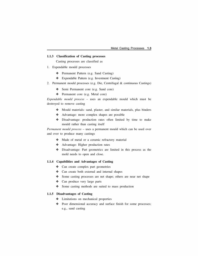
1.1.3 Classification of Casting processes
Casting processes are classified as
1. Expendable mould processes
Permanent Pattern (e.g. Sand Casting)
Expendable Pattern (e.g. Investment Casting)
2. Permanent mould processes (e.g. Die, Centrifugal & continuous Castings)
Semi Permanent core (e.g. Sand core)
Permanent core (e.g. Metal core)
Expendable mould process – uses an expendable mould which must be
destroyed to remove casting
Mould materials: sand, plaster, and similar materials, plus binders
Advantage: more complex shapes are possible
Disadvantage: production rates often limited by time to make
mould rather than casting itself
Permanent mould process – uses a permanent mould which can be used over
and over to produce many castings
Made of metal or a ceramic refractory material
Advantage: Higher production rates
Disadvantage: Part geometrics are limited in this process as the
mold needs to open and close.
1.1.4 Capabilities and Advantages of Casting
Can create complex part geometries
Can create both external and internal shapes
Some casting processes are net shape; others are near net shape
Can produce very large parts
Some casting methods are suited to mass production
1.1.5 Disadvantages of Casting
Limitations on mechanical properties
Poor dimensional accuracy and surface finish for some processes;
e.g., sand casting
Metal Casting Processes 1.3
Safety hazards to workers due to hot molten metals
Environmental problems
1.1.6 Parts made by Casting
Big parts -Engine blocks and heads for automotive vehicles, wood
burning stoves, machine frames, railway wheels, pipes, bells, pump
housings
Small parts-Dental crowns, jewelry, small statues, frying pans
All varieties of metals can be cast - ferrous and nonferrous
1.1.7 Mould in Casting
Mould contains a cavity whose geometry determines part shape.
Actual size and shape of cavity must be slightly oversized to allow
for shrinkage of metal during solidification and cooling.
Moulds are made of a variety of materials, including sand, plaster,
ceramic.
Moulds are in two forms namely (a) open mould, simply a
container in the shape of the desired part; and (b) closed mould,
in which the mould geometry is more complex and requires a
gating system (passageway) leading into the cavity. (Fig 1.2)
Moulds are of the following types
Expendable moulds – These moulds are mixed with various types of binders
or bonding agents eg. Sand , Plaster, Ceramic Moulds. These moulds are able
to withstand high temperatures and mould is broken up to remove the casting
Permanent moulds-are moulds made of metal. These moulds are subjected to
a higher cooling rate and affects grain size. These are used repeatedly and
casting can be removed easily.
Composite moulds - are moulds made of two or more materials like sand,
graphite, metal etc.,. These moulds combines advantages of each material and
are used to control cooling rates, improve mould strength and optimize
economics of the process.
1.4 Manufacturing Technology I - www.airwalkbooks.com
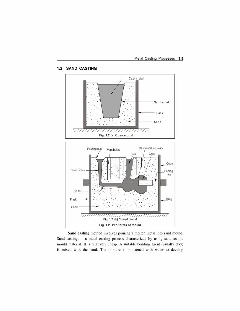
1.2 SAND CASTING
Sand casting method involves pouring a molten metal into sand mould.
Sand casting, is a metal casting process characterized by using sand as the
mould material. It is relatively cheap. A suitable bonding agent (usually clay)
is mixed with the sand. The mixture is moistened with water to develop
.
. .. .
. .... .
... .
. ... .
..
... .
. .... .. . .. ..
. ..
....
. ....
...
. .. ..
. . .. .
.. . .. .
. ...
.
....
.... ..
. ...
.....
..
. ...
... . .. ......
...
.. . .
.....
...
.. ...
....
. ...
C ast m eta l
F lask
Sand
Sand m ou ld
Fig. 1.2 (a) Open mould
Fig. 1.2. Two forms of mould
Metal Casting Processes 1.5
strength and plasticity of the clay and to make the aggregate suitable for
moulding. The term “sand casting” can also refer to an object produced via
the sand casting process. Sand castings are produced in specialized factories
called foundries.
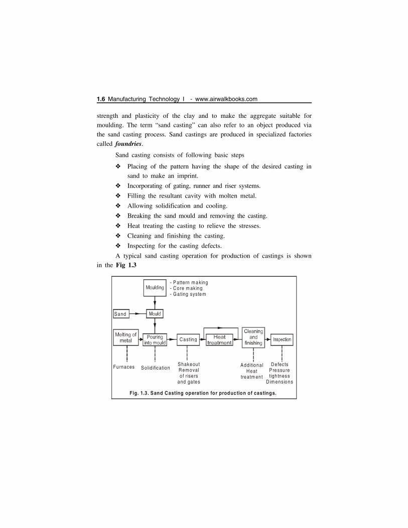
Sand casting consists of following basic steps
Placing of the pattern having the shape of the desired casting in
sand to make an imprint.
Incorporating of gating, runner and riser systems.
Filling the resultant cavity with molten metal.
Allowing solidification and cooling.
Breaking the sand mould and removing the casting.
Heat treating the casting to relieve the stresses.
Cleaning and finishing the casting.
Inspecting for the casting defects.
A typical sand casting operation for production of castings is shown
in the Fig 1.3
Sand
C asting
Furnaces So lid ificationShakeou tR em oval o f rise rs
and ga tes
D e fectsPre ssu re tigh tness
D im ensio ns
Additional H eat
treatm en t
- P attern m a king- C ore m aking- G a ting syste m
Fig. 1.3. Sand Casting operation for production of castings.
1.6 Manufacturing Technology I - www.airwalkbooks.com
1.2.1 Advantages and disadvantages of sand casting
Advantages of sand casting
Low cost of mould materials and equipment.
Large casting dimensions may be obtained.
Wide variety of metals and alloys (ferrous and non-ferrous) can
be cast (including high melting point metals) using this method.
Disadvantages of sand casting
Rough surface.
Poor dimensional accuracy.
High machining tolerances.
Coarse Grain structure.
Limited wall thickness: not higher than 2.5 to 5 mm.
1.3 SAND MOULD
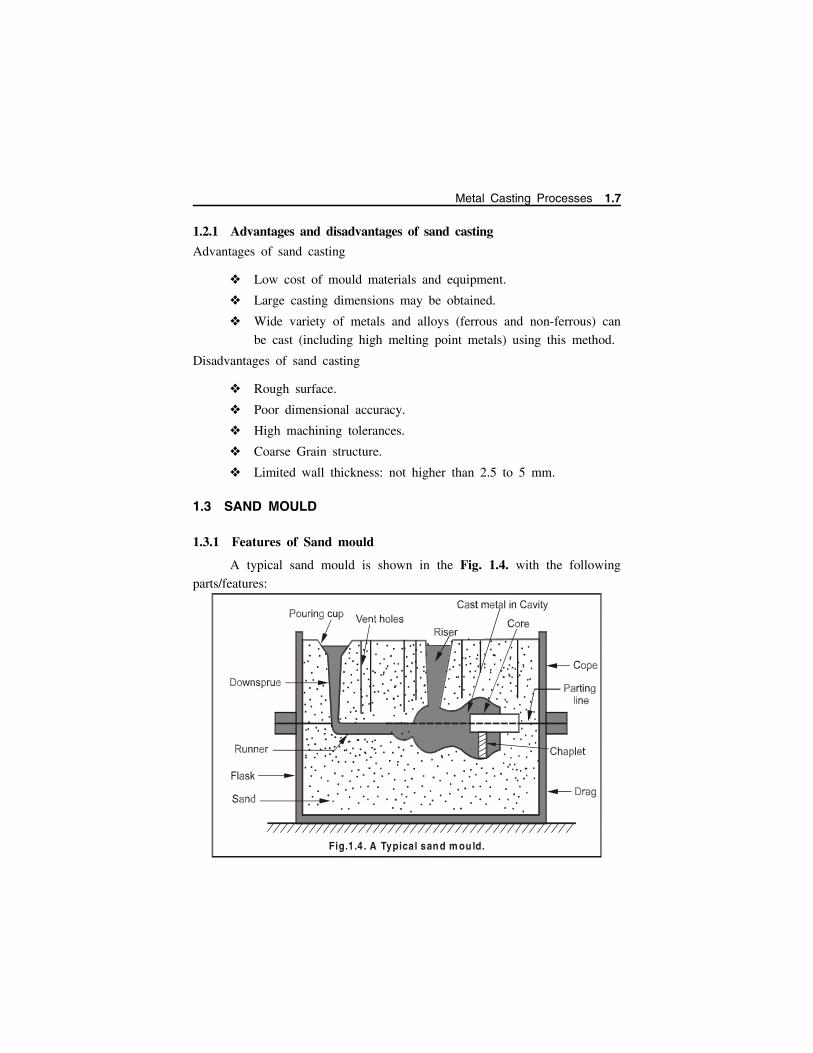
1.3.1 Features of Sand mould
A typical sand mould is shown in the Fig. 1.4. with the following
parts/features:
Fig.1.4. A Typical sand m ould.
Metal Casting Processes 1.7
Cope / Drag: The mould is made of two parts, the top half is called the
cope, and bottom part is the drag.
Mould cavity: The liquid flows into the gap between the two parts, called
the mould cavity.
Pattern: The geometry of the cavity is created by the use of a wooden shape, called
the pattern. The shape of the pattern is (almost) identical to the shape of the part
we need to make.
Sprue: A funnel shaped cavity at the top of the funnel is the pouring cup;
the pipe-shaped neck of the funnel is the sprue – the liquid metal is poured
into the pouring cup, and flows down the sprue.
Runners: The runners are the horizontal hollow channels that connect the
bottom of the sprue to the mould cavity. The region where the runner joins
with the cavity is called the gate.
Risers: Some extra cavities are made connecting to the top surface of the
mould. Excess metal poured into the mould flows into these cavities called
risers. They act as reservoirs; as the metal solidifies inside the cavity, it
shrinks, and the extra metal from the risers flows back down to avoid holes
in the cast part.
Vents: Vents are narrow holes connecting the cavity to the atmosphere to
allow gas and the air in the cavity to escape.
Cores: Many cast parts have interior holes (hollow parts), or other cavities
in their shape that are not directly accessible from either piece of the mould.
Such interior surfaces are generated by inserts called cores.
Cores are made by baking sand with some binder so that they can
retain their shape when handled. The mould is assembled by placing the core
into the cavity of the drag, and then placing the cope on top, and locking
the mould. After the casting is done, the sand is shaken off, and the core is
pulled away and usually broken off.
Chaplets: Chaplets are metal distance pieces inserted in a mould either to
prevent shifting of mould or to locate core surfaces. The distance pieces in
form of chaplets are made of parent metal of which the casting is. These are
1.8 Manufacturing Technology I - www.airwalkbooks.com

placed in mould cavity suitably which positions core and to give extra support
to core and mould surfaces. Its main objective is to impart good alignment
of mould and core surfaces and to achieve directional solidification.
Chills: Chills are pieces of copper, brass or aluminium and are inserted into
the mould’s inner surface. Water passages in the mould or cooling fins made
on outside the mould surface are blown by air otherwise water mist will
create chilling effect. A chill is used to promote directional solidification.
1.3.2 Desirable Mould Properties and Characteristics
The desirable mould properties and characteristics are
Strength - to maintain shape and resist erosion
Permeability - to allow hot air and gases to pass through voids in
sand
Thermal stability - to resist cracking on contact with molten metal
Collapsibility - ability to give way and allow casting to shrink
without cracking the casting
Reusability - can be reused to make other moulds
Size and shape of sand :
Small grain size - Better surface finish Large grain size - To allow escape of gases during pouring Irregular grain shapes - Strengthen moulds due to interlocking
but reduces permeability
1.3.3 Steps/ Procedure for making sand mould for a two piece pattern
The steps involved in making a sand mould is discussed below:
(Fig. 1.5)
Selection of Mould box / Flask:Select a suitable size of moulding box for creating suitable wall
thickness for a two piece pattern. The moulding box must be of proper size
to adjust mould cavity, riser and the gating system (sprue, runner, and gates
etc.).
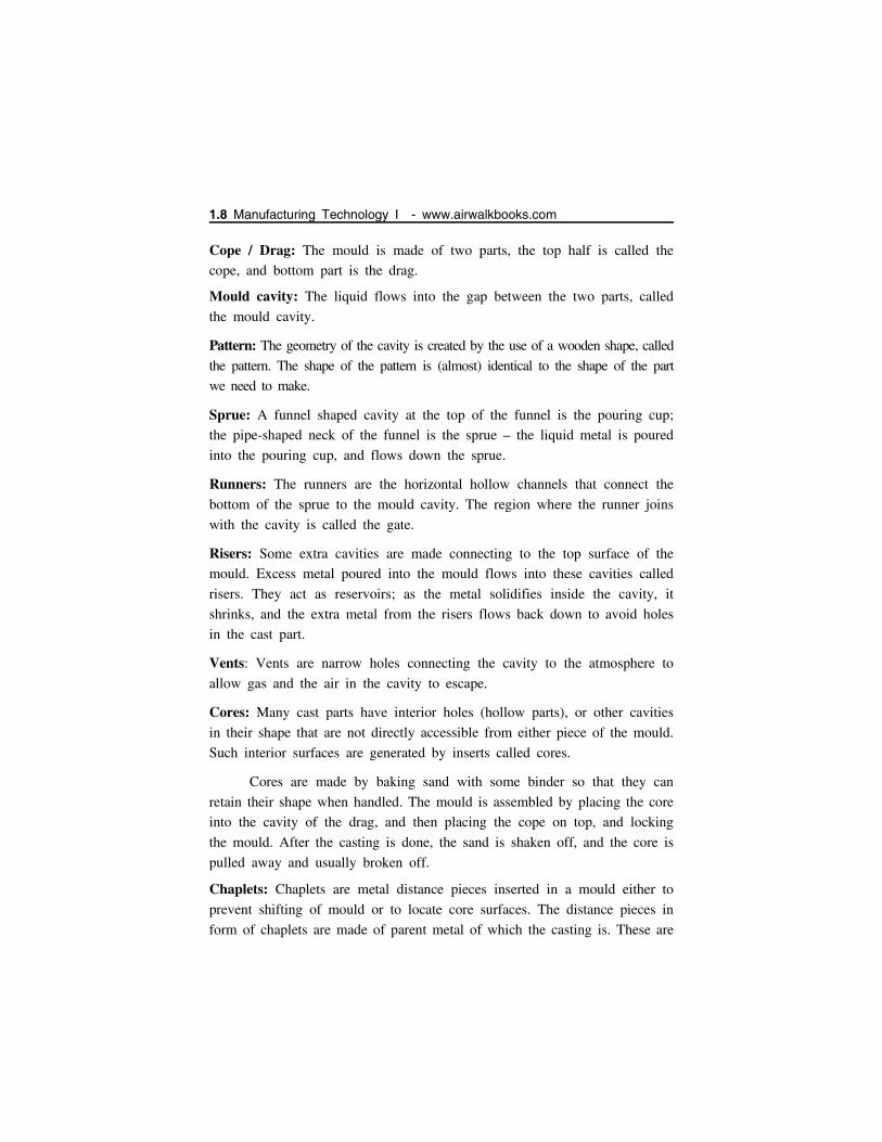
Preparation of Drag: Place the drag portion of the pattern with the parting surface down
on the bottom (ram-up) board as shown in Fig. 1.5 (a).
Metal Casting Processes 1.9
The facing sand is then sprinkled carefully all around the pattern
so that the pattern does not stick with moulding sand during
withdrawal of the pattern.
The drag is then filled with loosely prepared moulding sand and
ramming of the moulding sand is done uniformly in the moulding
box around the pattern. Fill the moulding sand once again and
then perform ramming. Repeat the process three four times.
The excess amount of sand is then removed using strike off bar
to bring moulding sand at the same level of the moulding flask
height to complete the drag.
Fig. 1.5 (a)
Fig. 1.5 (b)
Drag
1.10 Manufacturing Technology I - www.airwalkbooks.com
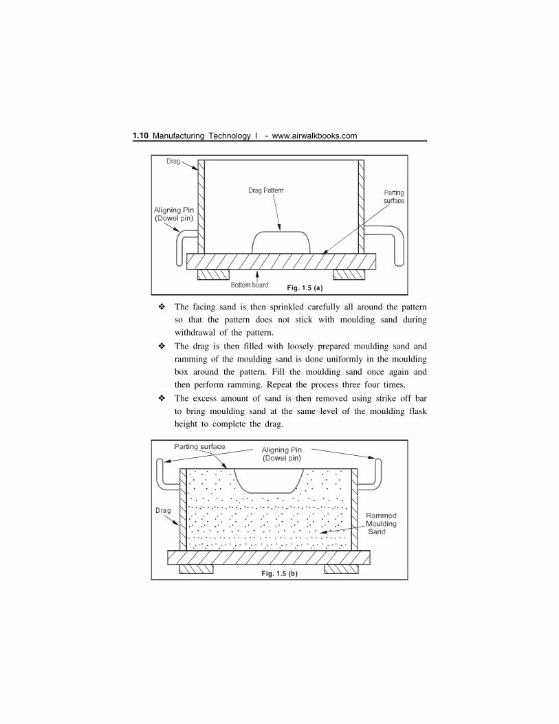
The drag is then rolled over by 180 and the parting sand is
sprinkled over on the top of the drag [Fig. 1.5(b)].
Preparation of Cope: Now the cope pattern is placed on the drag pattern and alignment
is done using dowel pins.
Then cope (flask) is placed over the rammed drag and alignment
is done using the aligning pins.
Then the parting sand is sprinkled all around the cope pattern.
Sprue (runner) and riser pins are placed in vertical position at
suitable locations using the support of moulding sand. It will help
to form suitable size cavities for pouring molten metal etc.
[Fig. 1.5(c)]. They should not be located too close to the pattern
or mould cavity otherwise they may chill the casting
Now fill the cope with moulding sand and ram uniformly.
Strike off the excess sand from the top of the cope.
Remove sprue and riser pins and create vent holes in the cope
with a vent wire. The basic purpose of creating vent holes in cope
is to permit the escape of gases generated during pouring and
solidification of the casting.
Sprinkle parting sand over the top of the cope surface and roll
over the cope on the bottom board.
Fig. 1.5 (c)
Sprue pin Riser p in
Cope
Lug
Drag
Aligning P in
Pattern
Metal Casting Processes 1.11

Cutting of Gate & Pouring of Metal
Rap and remove both the cope and drag patterns and repair the
mould suitably if needed and dressing is applied
The gate is then cut connecting the lower base of sprue basin with
runner and the mould cavity.
Apply mould coating with a swab and bake the mould in case of
a dry sand mould.
Set the cores in the mould, if needed and close the mould by
inverting cope over drag.
The cope is then clamped with drag and the mould is ready for
pouring, [Fig. 1.5(d)].
1.4 CONSTITUENTS OF MOULDING SANDThe main constituents of moulding sand are Silica sand, Binder,
Moisture content and Additives.
1.4.1 Silica sand
Silica sand (SiO2) in the form of granular quartz is the main
constituent of moulding sand having enough refractoriness which
can impart strength, stability and permeability to moulding and
core sand.
Fig. 1.5. S teps/procedure for making a sand mould.
Fig. 1.5 (d)
Pouring bas in
G ate
1.12 Manufacturing Technology I - www.airwalkbooks.com
Along with silica small amounts of iron oxide, alumina, lime stone,
magnesia, soda and potash are present as impurities.
The presence of excessive amounts of iron oxide, alkali oxides
and lime can lower the fusion point to a considerable extent which
is undesirable.
The silica sand can be specified according to the size (small, medium
and large silica sand grain) and the shape (angular, sub-angular and
rounded).
1.4.2 Binder
The binders are added to bind the silica sands and can be either
inorganic or organic substance.
The inorganic group includes clay, sodium silicate, port land
cement etc.
Organic groups are dextrin, molasses, cereal binders, linseed oil
and resins like phenol formaldehyde, urea formaldehyde etc.
Organic binders are mostly used for core making.
In foundry shop, the clay acts as binder which may be Kaolonite,
Ball clay, Fire clay, Limonite, Fuller’s earth and Bentonite (most
common). However, this clay alone cannot develop bonds among
sand grains without the presence of moisture in moulding sand
and core sand.
1.4.3 Moisture / Water
The amount of moisture content in the moulding sand varies
generally between 2 to 8 percent.
This amount is added to the mixture of clay and silica sand for
developing bonds. This is the amount of water required to fill the
pores between the particles of clay without separating them.
This amount of water is held rigidly by the clay and is mainly
responsible for developing the strength in the sand. The effect of
clay and water decreases permeability with increasing clay and
moisture content.
Metal Casting Processes 1.13

1.4.4 Additives
For increasing the moulding sand characteristics some other additional
materials besides basic constituents are added which are known as additives.
Additives are the materials generally added to the moulding and core sand.
Some commonly used additives for enhancing the properties of moulding and
core sands are discussed below.
1.4.4.1 Corn flour and Dextrin
It belongs to the starch family of carbohydrates and is used to
increase the collapsibility of the moulding and core sand.
It is completely volatilized by heat in the mould, thereby leaving
space between the sand grains. This allows free movement of sand
grains, which finally gives rise to mould wall movement and
decreases the mould expansion and hence defects in castings.
Corn sand if added to moulding sand and core sand improves
significantly strength of the mould and core.
1.4.4.2 Coal dust
Coal dust is added mainly for producing a reducing atmosphere
during casting.
This reducing atmosphere results in any oxygen in the pores
becoming chemically bound so that it cannot oxidize the metal.
It is usually added in the moulding sands for making moulds for
production of grey iron and malleable cast iron castings.
1.4.4.3 Sea coal and Pitch
Sea coal is the fine bituminous coal powder which occupies the pores
of the silica sand grains in moulding sand and core sand. It can be added
from 0.02 % to 2% in mould and core sand .When heated, it changes to
coke which fills the pores and is unaffected by water and does not allow the
sand to move. Thus, sea coal reduces the mould wall movement and the
permeability in mould and core sand and hence makes the mould and core
surface clean and smooth.
1.14 Manufacturing Technology I - www.airwalkbooks.com
1.4.4.4 Wood flour
This is a fibrous material mixed with a granular material like sand;
its relatively long thin fibers prevent the sand grains from making
contact with one another.
It can be added from 0.05 % to 2% in mould and core sand.
It volatilizes when heated, thus allowing the sand grains to expand.
It will increase mould wall movement and decrease expansion
defects.
It also increases collapsibility of both mould and the core.
1.4.4.5 Silica flour
It is called as pulverized silica and it can be easily added up to
3% which increases the hot strength and finish on the surfaces of
the moulds and cores.
It also reduces metal penetration in the walls of the moulds and
cores.
1.5 TYPES OF MOULDING SANDS
1.5.1 Green sand
Green sand is tempered or natural sand.
It is prepared by mixing of silica sand with 18 to 30 percent clay
and moisture content from 6 to 8%.
The clay and water furnish the bond for green sand.
It is fine, soft, light, and porous.
Green sand is damp, when squeezed in the hand it retains the
shape and the impression given to it under pressure.
Moulds prepared by this sand do not require backing and hence
are known as green sand moulds.
This sand is easily available and at low cost.
It is commonly employed for production of ferrous and non-ferrous
castings.
Metal Casting Processes 1.15
1.5.2 Dry sand
Green sand that has been dried or baked in suitable oven after the
making mould and core is called dry sand.
It possesses more strength, rigidity and thermal stability.
It is mainly suitable for larger castings.
Moulds prepared in this sand are known as dry sand moulds.
1.5.3 Loam sand
Loam is mixture of sand and clay with water to a thin plastic
paste.
Loam sand possesses high clay as much as 30-50% and 18% water.
Patterns are not used for loam moulding and shape is given to
mould by sweeps.
This is particularly employed for loam moulding used for large
grey iron castings.
1.5.4 Facing sand
Facing sand is just prepared and forms the face of the mould. It
is directly applied next to the surface of the pattern and it comes
into contact with molten metal when the mould is poured.
Initial coating around the pattern and hence for mould surface is
given by this sand.
This sand is subjected to the most severe conditions and therefore
must possess high strength refractoriness.
It is made of silica sand and clay, without the addition of any
used sand.
Different forms of carbon are used to prevent the metal burning
into the sand.
A facing sand mixture for green sand moulding of cast iron may
consist of 25% fresh and specially prepared sand 70% old sand
and 5% sea coal. They are sometimes mixed with 6-15 times as
much fine moulding sand to make facings.
1.16 Manufacturing Technology I - www.airwalkbooks.com

1.5.5 Backing sand
Backing sand (or) floor sand is used to back up the facing sand
and is used to fill the whole volume of the moulding flask.
Used moulding sand is mainly employed for this purpose.
The backing sand is sometimes called black sand because it is old
and repeatedly used. Moulding sand is black in color due to
addition of coal dust and burning caused on coming in contact
with the molten metal.
1.5.6 System sand
In mechanized foundries where machine moulding is employed, a
so-called system sand is used to fill the whole moulding flask.
In mechanical sand preparation and handling units, no facing sand
is used. The used sand is cleaned and re-activated by the addition
of water and special additives. This is known as system sand.
Since the whole mould is made of this system sand, the properties
such as strength, permeability and refractoriness of the moulding
sand must be higher than those of backing sand.
1.5.7 Parting sand
Parting sand without binder and moisture is used to keep the green
sand not to stick to the pattern and also to allow the cope and drag to separate
without clinging. This is clean clay-free silica sand which serves the same
purpose as parting dust.
1.5.8 Core sand
Core sand is used for making cores and it is sometimes known as oil
sand. This is highly rich silica sand mixed with oil binders such as core oil
which is composed of linseed oil, resin, light mineral oil and other binding
materials. Pitch (or) flours and water may also be used in large cores for the
sake of economy.
Metal Casting Processes 1.17
1.6 MOULDING SAND PROPERTIESThe basic properties required in moulding sand and core sand are
described below.
1.6.1 Refractoriness
Refractoriness is defined as the ability of moulding sand to
withstand high temperatures without breaking down (or) fusing
thus facilitating to get a sound casting.
It is a highly important characteristic of moulding sands.
Refractoriness can only be increased to a limited extent.
Moulding sand with poor refractoriness may burn on to the casting
surface and no smooth casting surface can be obtained.
The degree of refractoriness depends on the SiO2 i.e. quartz
content, and the shape and grain size of the particle. The higher
the SiO2 content and the rougher the grain volumetric composition,
the higher is the refractoriness of the moulding sand and core sand.
Refractoriness is measured by the sinter point of the sand rather
than its melting point.
1.6.2 Permeability
It is also termed as porosity of the moulding sand in order to
allow the escape of any air, gases or moisture present or generated
in the mould when the molten metal is poured into it.
All the gases generated during pouring and solidification process
must escape otherwise the casting becomes defective.
Permeability is a function of grain size, grain shape, moisture and
clay contents in the moulding sand.
The extent of ramming of the sand directly affects the permeability
of the mould.
Permeability of mould can be further increased by venting using
vent rods.
1.18 Manufacturing Technology I - www.airwalkbooks.com
1.6.3 Cohesiveness
It is a property of moulding sand by virtue of which the sand grain
particles interact and attract each other within the moulding sand. Thus, the
binding capability of the moulding sand gets enhanced to increase the green,
dry and hot strength property of moulding and core sand.
1.6.4 Green strength
The green sand, after water has been mixed into it, must have
sufficient strength and toughness to permit the making and
handling of the mould. For this, the sand grains must be adhesive,
i.e. they must be capable of attaching themselves to another body.
Therefore sand grains having high adhesiveness will cling to the
sides of the moulding box.
By virtue of this property, the pattern can be taken out from the
mould without breaking the mould and also the erosion of mould
wall surfaces does not occur during the flow of molten metal.
The green strength also depends upon the grain shape and size,
amount and type of clay and the moisture content.
1.6.5 Dry strength
As soon as the molten metal is poured into the mould, the moisture
in the sand layer adjacent to the hot metal gets evaporated and
this dry sand layer must have sufficient strength to its shape in
order to avoid erosion of mould wall during the flow of molten
metal.
The dry strength also prevents the enlargement of mould cavity
caused by the metallostatic pressure of the liquid metal.
1.6.6 Flowability (or) plasticity
It is the ability of the sand to get compacted and behave like a
fluid. It will flow uniformly to all portions of pattern when
rammed and distribute the ramming pressure evenly all around in
all directions.
Generally sand particles resist moving around corners (or)
projections.
Metal Casting Processes 1.19
In general, flowability increases with decrease in green strength
and decrease in grain size.
The flowability also varies with moisture and clay content.
1.6.7 Adhesiveness
It is property of moulding sand that allows it to stick or adhere with
foreign materials also with inner wall of moulding box.
1.6.8 Collapsibility
After the molten metal in the mould gets solidified, the sand mould
must be collapsible so that free contraction of the metal occurs
and this would naturally avoid the tearing or cracking of the
contracting metal.
In absence of this property the contraction of the metal is hindered
by the mould and thus results in tears and cracks in the casting.
This property is highly desired in cores
1.6.9 Classification of Moulding Processes
Moulding processes can be classified as
(i) Classification based on the method used
Bench moulding, Floor moulding, Pit moulding., Machine moulding.
(ii) Classification based on the mould material used:
Green sand moulding, Dry sand moulding, Skin dried moulding, Core
sand moulding, loam moulding, Carbon-dioxide moulding, Shell moulding,
Plaster moulding, Metallic moulding and Loam moulding Some of the
important moulding methods are discussed below.
1.6.9.1 Bench Moulding
This type of moulding is preferred for small jobs. The whole moulding
operation is carried out on a bench of convenient height. In this process, a
minimum of two flasks, namely cope and drag moulding flasks are necessary.
But in certain cases, the number of flasks may increase depending upon the
number of parting surfaces required.
1.20 Manufacturing Technology I - www.airwalkbooks.com
1.6.9.2 Floor Moulding
This type of moulding is preferred for medium and large size jobs. In
this method, only drag portion of moulding flask is used to make the mould and
the floor itself is utilized as drag and it is usually performed with dry sand.
1.6.9.3 Pit Moulding
Usually large castings are made in pits instead of drag flasks because
of their huge size. In pit moulding, the sand under the pattern is rammed by
bedding-in process. The walls and the bottom of the pit are usually reinforced
with concrete and a layer of coke is laid on the bottom of the pit to enable
easy escape of gas. The coke bed is connected to atmosphere through vent
pipes which provide an outlet to the gases. One box is generally required to
complete the mould, runner, sprue, pouring basin and gates are cut in it.
1.6.9.4 Machine Moulding
For mass production of the casting, the general hand moulding
technique proves un-economical and in-efficient. The main advantage of
machine moulding, besides the saving of labor and working time, is the
accuracy and uniformity of the castings and
or even the cost of machining on the casting can be reduced drastically
because it is possible to maintain the tolerances within narrow limits on
casting by using machine moulding method. Moulding machines thus prepare
the moulds at a faster rate and also eliminate the need of employing skilled
moulders. The main operations performed by moulding machines are ramming
of the moulding sand, roll over the mould, form gate, rapping the pattern and
its withdrawal.
1.6.9.5 Loam Moulding
Loam moulding uses loam sand to prepare a loam mould. It is such
a moulding process in which use of pattern is avoided and hence it differs
from the other moulding processes. Initially the loam sand is prepared with
the mixture of moulding sand and clay made in form of a paste by suitable
addition of water. Firstly a rough structure of cast article is made by hand
using bricks and loam sand and it is then given a desired shape by means
of strickles and sweep patterns. Mould is thus prepared. It is then baked to
Metal Casting Processes 1.21
give strength to resist the flow of molten metal. This method of moulding is
used where large castings are required in numbers. Thus it enables the
reduction in time, labor and material which would have been spent in making
a pattern. But this system is not popular for the reason that it takes lots of
time in preparing mould and requires special skill. The cope and drag part
of mould are constructed separately on two different iron boxes using different
sizes of strickles and sweeps etc. and are assembled together after baking. It
is important to note that loam moulds are dried slowly, completely and are
used for large regular shaped castings like chemical pans, drums etc.
1.6.9.6 Dry sand moulding
Dry moulding sand differs from the green moulding sand in the
sense that it contains binders (like clay, bentonite, molasses etc.)
which harden when the mould is heated and dried.
A typical dry sand mixture (for making non-ferrous castings)
consists of new silica sand 30%, coal dust 20% and bentonite 10%
A dry sand mould is prepared in the same manner as a green sand
mould; however it is baked at 300 to 70F for 8 to 48 hours
depending upon binders used and the amount of sand surface to
be dried.
Drying of moulds can be of two types: skin dried and complete
mould drying. Common methods of drying the mould are hot air
and gas or oil flame. Skin drying is accomplished with the aid of
torches directed at the mould surface.
Advantages
Dry sand moulds possess high strength.
They are more permeable as compared to green sand moulds.
Castings produced from dry sand moulds possess clean and smooth
surfaces.
As compared to green sand moulding, dry sand moulding turns
out castings with less defects.
Dry sand moulding imparts better overall dimensional accuracy to
the moulds and castings as compared to green sand moulding.
1.22 Manufacturing Technology I - www.airwalkbooks.com
Disadvantages
Dry sand moulding involves more labour and consumes more time
in completing the mould. Mould baking is an extra work as
compared to that required in green sand moulding.
Dry sand moulding is more expensive as compared to green sand
moulding.
Dry sand moulding involves chances of hot tears occurring in the
castings.
Because of baking, a mould may distort.
Dry sand moulding involves a longer processing cycle as compared
to green sand moulding.
Dry sand moulding gives a slower rate of production as compared
to green sand moulding.
Applications
Dry sand moulding is used for making medium to large size ferrous
castings such as Large rolls, Housings, Gears, Machinery components.
1.6.9.7 Skin-dried moulding
A skin-dried mould is intermediate between green sand mould and dry
sand mould. Whereas a dry sand mould has its entire surface dried, a skin
dried mould has its (6 to 25 mm) skin dried.
Moisture of the skin is removed either by storing the mould for some
time or with a gas torch. It has some advantages of both green and dry sand
moulding. It is used for large moulds and moulds for pit moulding.
1.6.10 Hand Tools Used In Foundry Shop (Fig 1.6 (a to n))
Hand riddle
Hand riddle consists of a screen of standard
circular wire mesh equipped with circular wooden
frame used for cleaning the sand for removing
foreign material. Fig. 1.6 (a).
Fig. 1 .6 (a) Hand riddle
Metal Casting Processes 1.23
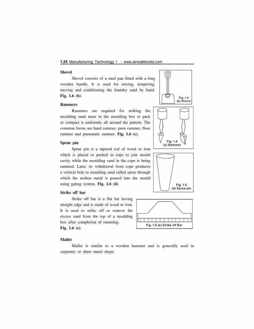
Shovel
Shovel consists of a steel pan fitted with a long
wooden handle. It is used for mixing, tempering,
moving and conditioning the foundry sand by hand.
Fig. 1.6 (b).
Rammers
Rammers are required for striking the
moulding sand mass in the moulding box to pack
or compact it uniformly all around the pattern. The
common forms are hand rammer, peen rammer, floor
rammer and pneumatic rammer. Fig. 1.6 (c).
Sprue pin
Sprue pin is a tapered rod of wood or iron
which is placed or pushed in cope to join mould
cavity while the moulding sand in the cope is being
rammed. Later, its withdrawal from cope produces
a vertical hole in moulding sand called sprue through
which the molten metal is poured into the mould
using gating system. Fig. 1.6 (d).
Strike off bar
Strike off bar is a flat bar having
straight edge and is made of wood or iron.
It is used to strike off or remove the
excess sand from the top of a moulding
box after completion of ramming.
Fig. 1.6 (e).
Mallet
Mallet is similar to a wooden hammer and is generally used in
carpentry or sheet metal shops.
Fig. 1.6(b) Shovel
Fig. 1.6(c) Rammer
Fig. 1.6(d) Sprue pin
Fig. 1.6 (e) Strike o ff Bar
1.24 Manufacturing Technology I - www.airwalkbooks.com
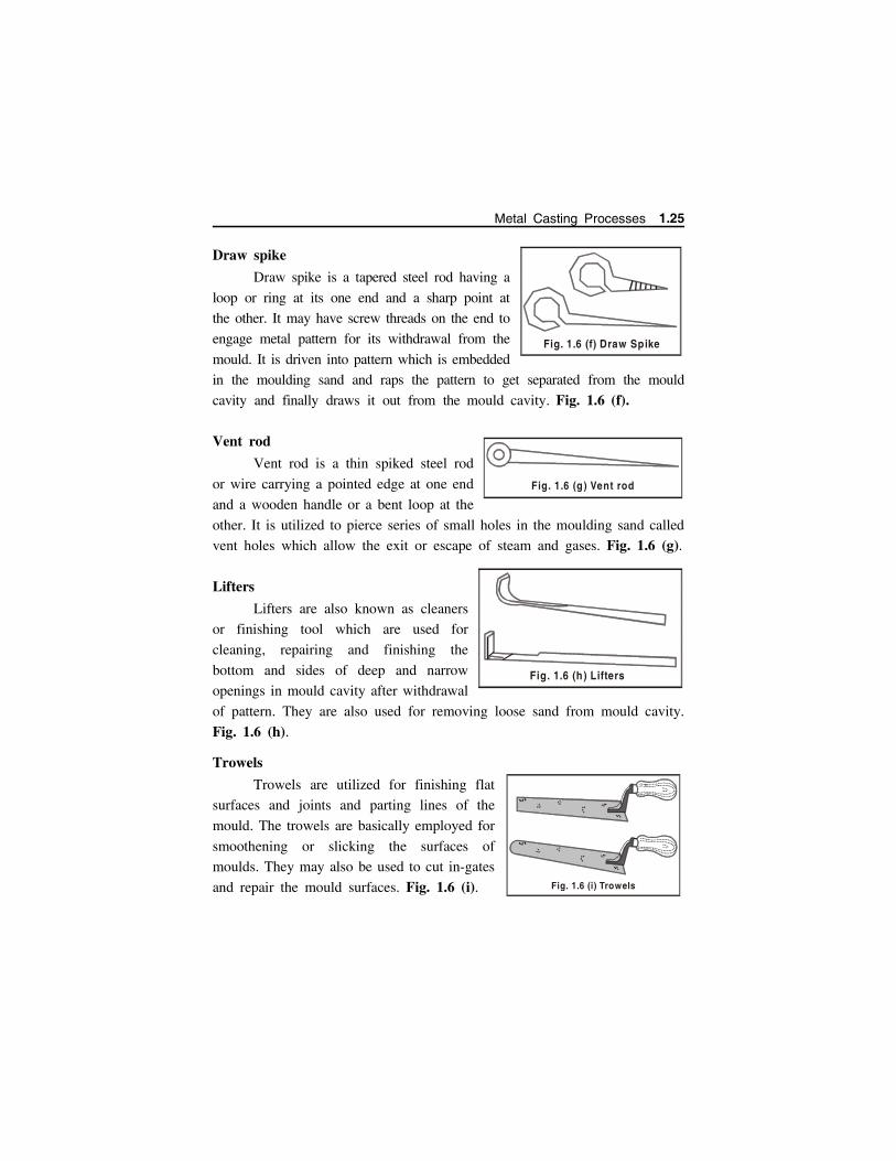
Draw spike
Draw spike is a tapered steel rod having a
loop or ring at its one end and a sharp point at
the other. It may have screw threads on the end to
engage metal pattern for its withdrawal from the
mould. It is driven into pattern which is embedded
in the moulding sand and raps the pattern to get separated from the mould
cavity and finally draws it out from the mould cavity. Fig. 1.6 (f).
Vent rod
Vent rod is a thin spiked steel rod
or wire carrying a pointed edge at one end
and a wooden handle or a bent loop at the
other. It is utilized to pierce series of small holes in the moulding sand called
vent holes which allow the exit or escape of steam and gases. Fig. 1.6 (g).
Lifters
Lifters are also known as cleaners
or finishing tool which are used for
cleaning, repairing and finishing the
bottom and sides of deep and narrow
openings in mould cavity after withdrawal
of pattern. They are also used for removing loose sand from mould cavity.
Fig. 1.6 (h).
Trowels
Trowels are utilized for finishing flat
surfaces and joints and parting lines of the
mould. The trowels are basically employed for
smoothening or slicking the surfaces of
moulds. They may also be used to cut in-gates
and repair the mould surfaces. Fig. 1.6 (i).
Fig. 1.6 (f) Draw Spike
Fig. 1.6 (g ) Vent rod
Fig. 1.6 (h) Lifters
Fig. 1.6 (i) Trowels
Metal Casting Processes 1.25
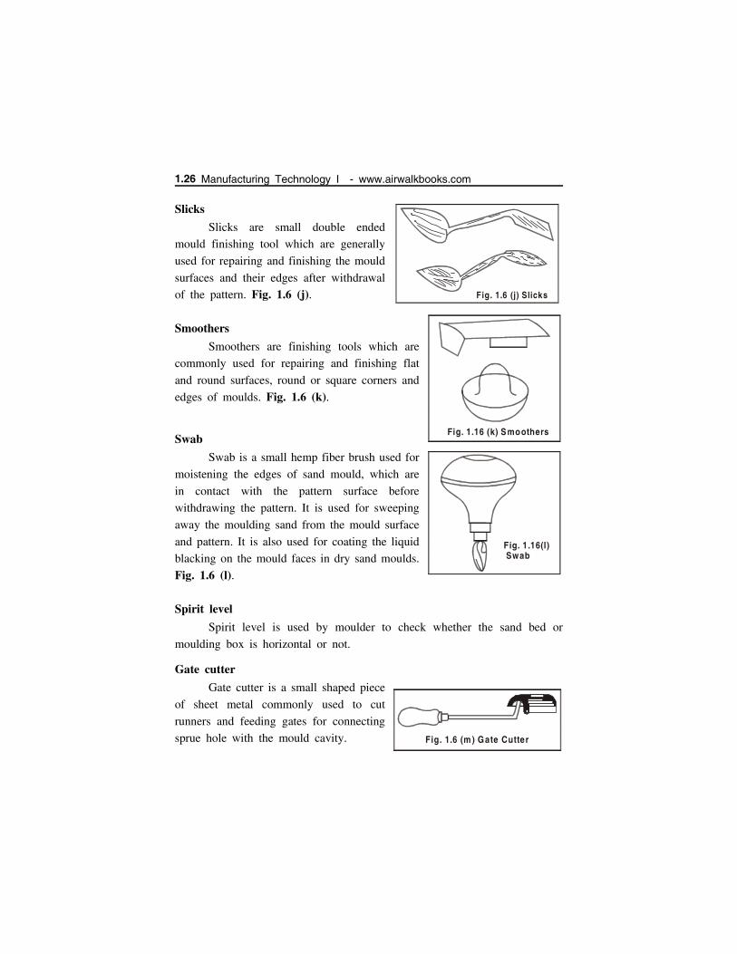
Slicks
Slicks are small double ended
mould finishing tool which are generally
used for repairing and finishing the mould
surfaces and their edges after withdrawal
of the pattern. Fig. 1.6 (j).
Smoothers
Smoothers are finishing tools which are
commonly used for repairing and finishing flat
and round surfaces, round or square corners and
edges of moulds. Fig. 1.6 (k).
Swab
Swab is a small hemp fiber brush used for
moistening the edges of sand mould, which are
in contact with the pattern surface before
withdrawing the pattern. It is used for sweeping
away the moulding sand from the mould surface
and pattern. It is also used for coating the liquid
blacking on the mould faces in dry sand moulds.
Fig. 1.6 (l).
Spirit level
Spirit level is used by moulder to check whether the sand bed or
moulding box is horizontal or not.
Gate cutter
Gate cutter is a small shaped piece
of sheet metal commonly used to cut
runners and feeding gates for connecting
sprue hole with the mould cavity.
Fig. 1.6 (j) Slicks
Fig. 1.16 (k) Smoothers
Fig. 1.16(l) Swab
Fig. 1.6 (m ) Gate Cutter
1.26 Manufacturing Technology I - www.airwalkbooks.com
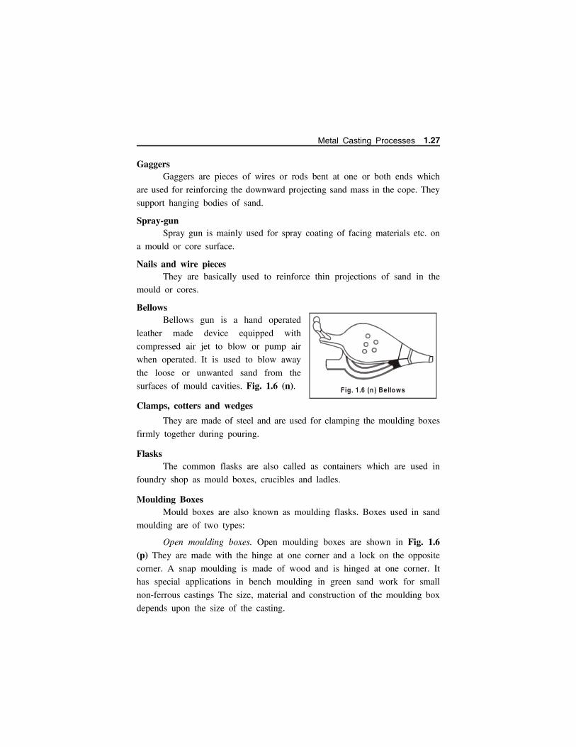
GaggersGaggers are pieces of wires or rods bent at one or both ends which
are used for reinforcing the downward projecting sand mass in the cope. They
support hanging bodies of sand.
Spray-gunSpray gun is mainly used for spray coating of facing materials etc. on
a mould or core surface.
Nails and wire piecesThey are basically used to reinforce thin projections of sand in the
mould or cores.
BellowsBellows gun is a hand operated
leather made device equipped with
compressed air jet to blow or pump air
when operated. It is used to blow away
the loose or unwanted sand from the
surfaces of mould cavities. Fig. 1.6 (n).
Clamps, cotters and wedges
They are made of steel and are used for clamping the moulding boxes
firmly together during pouring.
FlasksThe common flasks are also called as containers which are used in
foundry shop as mould boxes, crucibles and ladles.
Moulding BoxesMould boxes are also known as moulding flasks. Boxes used in sand
moulding are of two types:
Open moulding boxes. Open moulding boxes are shown in Fig. 1.6(p) They are made with the hinge at one corner and a lock on the opposite
corner. A snap moulding is made of wood and is hinged at one corner. It
has special applications in bench moulding in green sand work for small
non-ferrous castings The size, material and construction of the moulding box
depends upon the size of the casting.
Fig. 1.6 (n ) Bellows
Metal Casting Processes 1.27
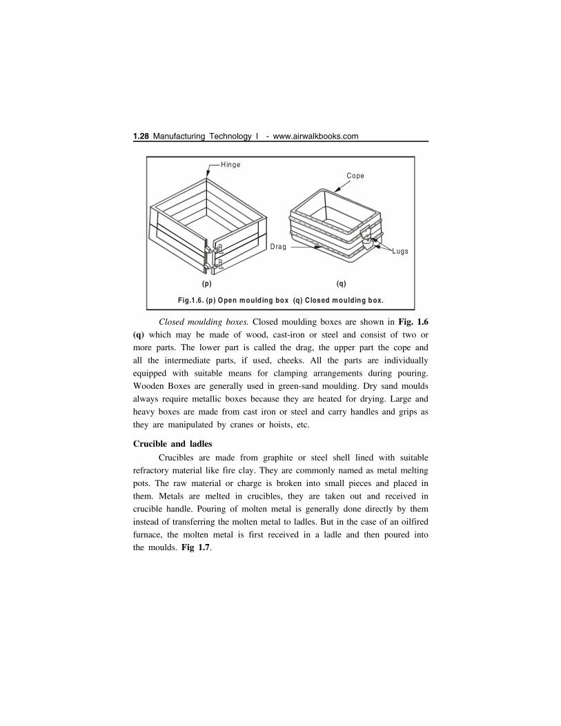
Closed moulding boxes. Closed moulding boxes are shown in Fig. 1.6(q) which may be made of wood, cast-iron or steel and consist of two or
more parts. The lower part is called the drag, the upper part the cope and
all the intermediate parts, if used, cheeks. All the parts are individually
equipped with suitable means for clamping arrangements during pouring.
Wooden Boxes are generally used in green-sand moulding. Dry sand moulds
always require metallic boxes because they are heated for drying. Large and
heavy boxes are made from cast iron or steel and carry handles and grips as
they are manipulated by cranes or hoists, etc.
Crucible and ladles
Crucibles are made from graphite or steel shell lined with suitable
refractory material like fire clay. They are commonly named as metal melting
pots. The raw material or charge is broken into small pieces and placed in
them. Metals are melted in crucibles, they are taken out and received in
crucible handle. Pouring of molten metal is generally done directly by them
instead of transferring the molten metal to ladles. But in the case of an oilfired
furnace, the molten metal is first received in a ladle and then poured into
the moulds. Fig 1.7.
Hinge
(p)
Drag
Cope
Lugs
(q)
Fig.1.6. ) Open moulding box ) C losed (p (q moulding box.
1.28 Manufacturing Technology I - www.airwalkbooks.com
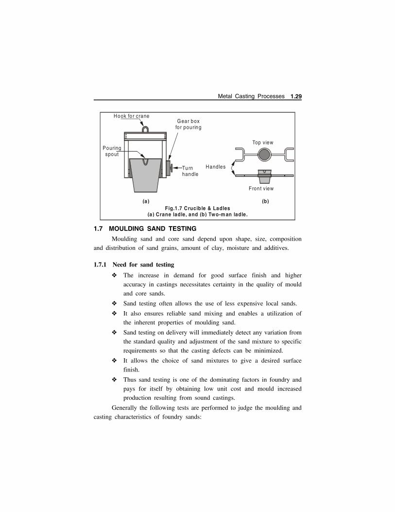
1.7 MOULDING SAND TESTING
Moulding sand and core sand depend upon shape, size, composition
and distribution of sand grains, amount of clay, moisture and additives.
1.7.1 Need for sand testing
The increase in demand for good surface finish and higher
accuracy in castings necessitates certainty in the quality of mould
and core sands.
Sand testing often allows the use of less expensive local sands.
It also ensures reliable sand mixing and enables a utilization of
the inherent properties of moulding sand.
Sand testing on delivery will immediately detect any variation from
the standard quality and adjustment of the sand mixture to specific
requirements so that the casting defects can be minimized.
It allows the choice of sand mixtures to give a desired surface
finish.
Thus sand testing is one of the dominating factors in foundry and
pays for itself by obtaining low unit cost and mould increased
production resulting from sound castings.
Generally the following tests are performed to judge the moulding and
casting characteristics of foundry sands:
Pouringspout
Hook fo r craneGear box
fo r pouring
Turnhandle
Handles
Top view
Fron t v iew
(a) (b)Fig.1 .7 Crucib le & Ladles
(a) Crane ladle, and (b) Two-m an ladle .
Metal Casting Processes 1.29
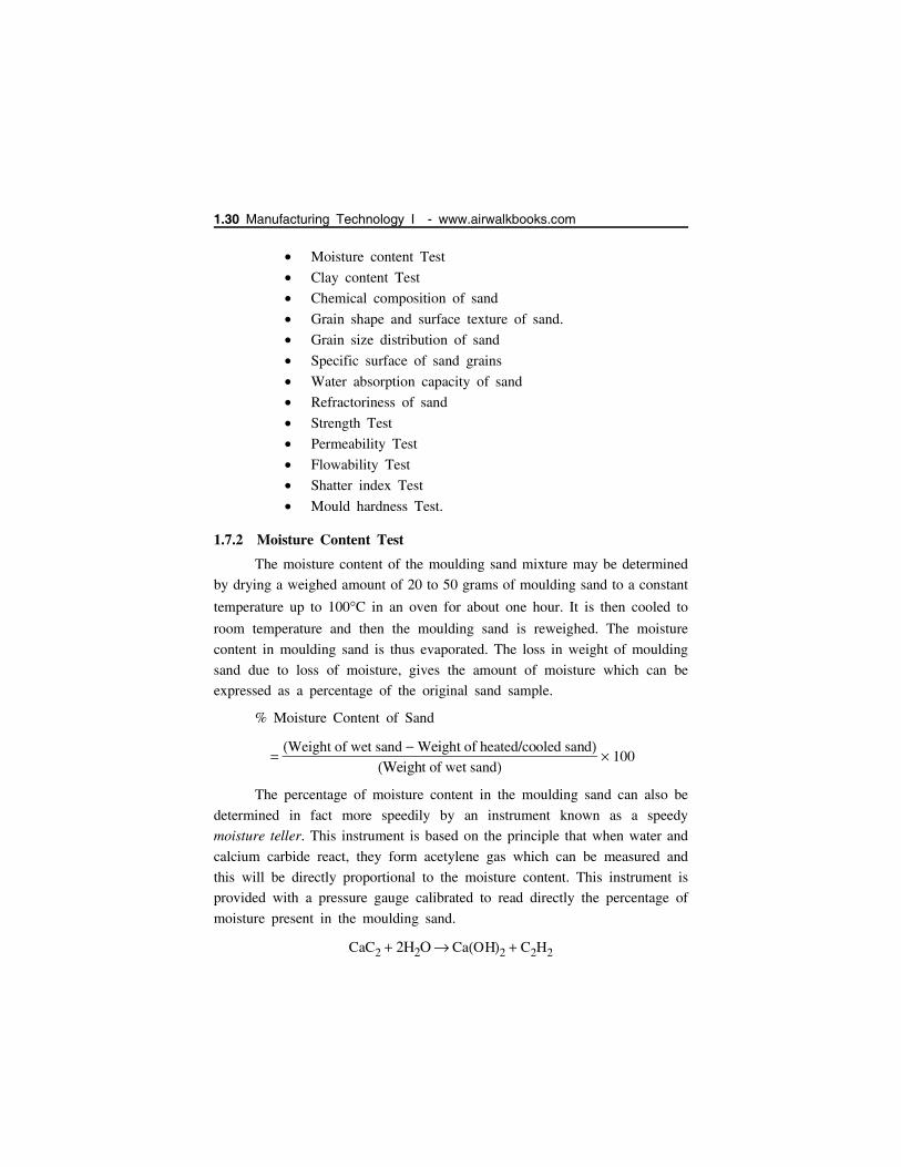
Moisture content Test
Clay content Test
Chemical composition of sand
Grain shape and surface texture of sand.
Grain size distribution of sand
Specific surface of sand grains
Water absorption capacity of sand
Refractoriness of sand
Strength Test
Permeability Test
Flowability Test
Shatter index Test
Mould hardness Test.
1.7.2 Moisture Content Test
The moisture content of the moulding sand mixture may be determined
by drying a weighed amount of 20 to 50 grams of moulding sand to a constant
temperature up to 100C in an oven for about one hour. It is then cooled to
room temperature and then the moulding sand is reweighed. The moisture
content in moulding sand is thus evaporated. The loss in weight of moulding
sand due to loss of moisture, gives the amount of moisture which can be
expressed as a percentage of the original sand sample.
% Moisture Content of Sand
Weight of wet sand Weight of heated/cooled sand
Weight of wet sand 100
The percentage of moisture content in the moulding sand can also be
determined in fact more speedily by an instrument known as a speedy
moisture teller. This instrument is based on the principle that when water and
calcium carbide react, they form acetylene gas which can be measured and
this will be directly proportional to the moisture content. This instrument is
provided with a pressure gauge calibrated to read directly the percentage of
moisture present in the moulding sand.
CaC2 2H2O CaOH2 C2H2
1.30 Manufacturing Technology I - www.airwalkbooks.com
Calcium carbide Water Calcium hyrdroxide Acetylene
Some moisture testing instruments are based on principle that the
electrical conductivity of sand varies with moisture content in it.
1.7.3 Clay Content Test
The clay content of the sand is determined as follows,
Take 50 gms of dry moulding sand and transfer to a wash bottle.
Add 475 cc of distilled water and 25 cc of 35 % NaOH solution
and agitate with a stirrer for 10 minutes.
Fill the water bottle with water upto mark. After the sand is settled
down drain out the water (clay is dissolved in water and is
removed). Repeat the above step for 7 times to ensure complete
removal of clay.
Dry the settled sand and weigh it say A gms.
Weight of clay 50 – A gms.
% content of clay 50 A/50 100
1.7.4 Grain Fineness Test (GFT)
GFT determines the grain size, distribution and grain fineness.
For carrying out grain fineness test a sample of dry silica sand
weighing 50 gms free from clay is placed on the top most sieve
bearing U.S. series equivalent number 6.
A set of eleven sieves having U.S. Bureau of standard meshes 6,
12, 20, 30, 40, 50, 70, 100, 140, 200 and 270 are mounted on a
mechanical shaker (Fig. 1.8).
The topmost sieve is coarsest and bottom most finest and the
inbetween sieves are in order of fineness from top to bottom.
The above setup is vibrated for 15 minutes.
After this weight of sand retained in each sieve is obtained and
percentage distribution of grains is computed.
To obtain the AFS (American Foundry Society) grain fineness
number, each % is multiplied by a factor. The resulting products
are added and divided by total percentage of sand grain retained.
Metal Casting Processes 1.31

AFS grain fineness number = Sum of products / Total sum of the % of
sand retained on pan and each sieve.
1.7.5 Refractoriness Test
The refractoriness of the moulding sand is judged by heating the
American Foundry Society (A.F.S) standard sand specimen to very
high temperature ranges (1300C) depending upon the type of
sand.
Timer
Adjusting K nobClam ping strip
Side flex ib le bar
Set o f s ieve
Toggle sw itch
Levellingscrew
Indica to rlam p
Spring
Bum per
Pannel
Base
Fig.1.8. Grain fineness testing mechanical shaker.
1.32 Manufacturing Technology I - www.airwalkbooks.com
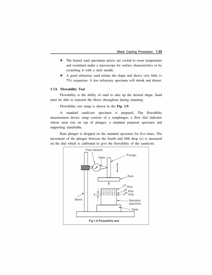
The heated sand specimens pieces are cooled to room temperature
and examined under a microscope for surface characteristics or by
scratching it with a steel needle.
A good refractory sand retains the shape and shows very little (<
7%) expansion. A less refractory specimen will shrink and distort.
1.7.6 Flowability Test
Flowability is the ability of sand to take up the desired shape. Sand
must be able to transmit the blows throughout during ramming.
Flowability test setup is shown in the Fig. 1.9.
A standard sand/core specimen is prepared. The flowability
measurement device setup consists of a ramplunger, a flow dial indicator
whose stem rest on top of plunger, a standard prepared specimen and
supporting stand/table.
Ram plunger is dropped on the standard specimen for five times. The
movement of the plunger between the fourth and fifth drop (x) is measured
on the dial which is calibrated to give the flowability of the sand/core.
Plunger
Flow indica tor
Stem
Stand
X
1 dropst
4 dropth
5th drop
Standard specim en
Table
Ram
Fig 1.9 Flowability test
Metal Casting Processes 1.33

1.7.7 Shatter Index Test
In this test, the A.F.S. standard sand specimen is rammed usually by
10 blows and then it is allowed to fall on a half inch mesh sieve from a
height of 6 ft. The weight of sand retained on the sieve is weighed. It is
then expressed as percentage of the total weight of the specimen which is a
measure of the shatter index.
1.7.8 Strength Test
Green strength and dry strength is the holding power of the various
bonding materials.
The most commonly performed test is compression test which is
carried out in a compression sand testing machine (Fig. 1.10).
Generally sand mixtures are tested for their compressive strength,
shear strength, tensile strength, transverse tests and bending
strength.
For carrying out these tests on green sand sufficient rammed
samples are prepared. The process of preparing sand specimen for
testing dry sand is similar to the process as prepared before, with
the difference that a split ram tube is used. The specimen for
testing bending strength is of a square cross section.
........ .... ...
..... ........
......... ......
.............
......
... ......
............. . ..
.....
... ... .... .
Lugs
H igh PressureM anom eter
Low P ressureM anom eter
Ad justing C ock
D ia l G auge
Peep Ho leM olding Sand
S pecimen
Fig. 1.10 Strength testing Machine.
Hand whee l
1.34 Manufacturing Technology I - www.airwalkbooks.com
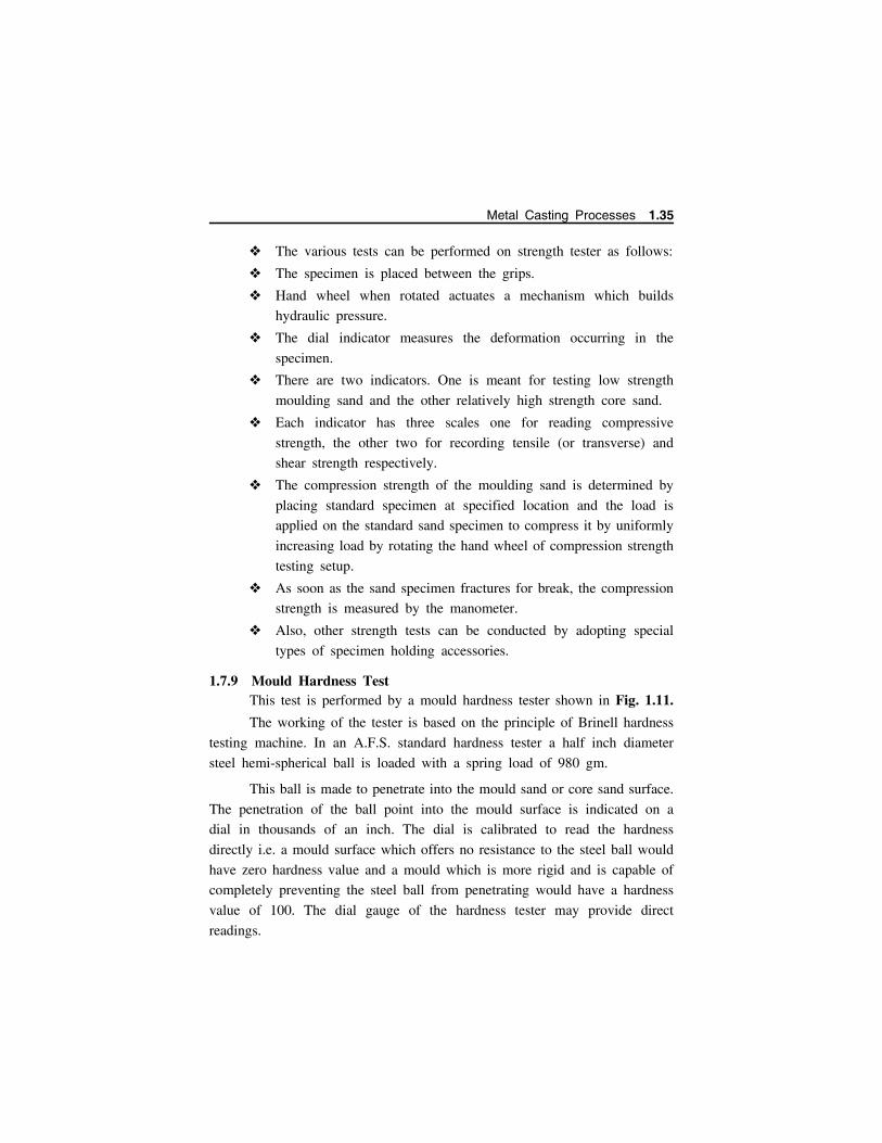
The various tests can be performed on strength tester as follows:
The specimen is placed between the grips.
Hand wheel when rotated actuates a mechanism which builds
hydraulic pressure.
The dial indicator measures the deformation occurring in the
specimen.
There are two indicators. One is meant for testing low strength
moulding sand and the other relatively high strength core sand.
Each indicator has three scales one for reading compressive
strength, the other two for recording tensile (or transverse) and
shear strength respectively.
The compression strength of the moulding sand is determined by
placing standard specimen at specified location and the load is
applied on the standard sand specimen to compress it by uniformly
increasing load by rotating the hand wheel of compression strength
testing setup.
As soon as the sand specimen fractures for break, the compression
strength is measured by the manometer.
Also, other strength tests can be conducted by adopting special
types of specimen holding accessories.
1.7.9 Mould Hardness TestThis test is performed by a mould hardness tester shown in Fig. 1.11.
The working of the tester is based on the principle of Brinell hardness
testing machine. In an A.F.S. standard hardness tester a half inch diameter
steel hemi-spherical ball is loaded with a spring load of 980 gm.
This ball is made to penetrate into the mould sand or core sand surface.
The penetration of the ball point into the mould surface is indicated on a
dial in thousands of an inch. The dial is calibrated to read the hardness
directly i.e. a mould surface which offers no resistance to the steel ball would
have zero hardness value and a mould which is more rigid and is capable of
completely preventing the steel ball from penetrating would have a hardness
value of 100. The dial gauge of the hardness tester may provide direct
readings.
Metal Casting Processes 1.35
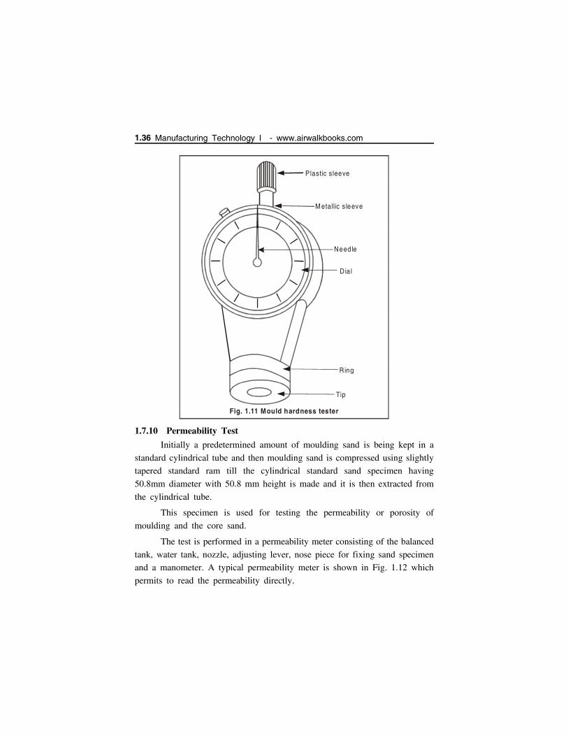
1.7.10 Permeability Test
Initially a predetermined amount of moulding sand is being kept in a
standard cylindrical tube and then moulding sand is compressed using slightly
tapered standard ram till the cylindrical standard sand specimen having
50.8mm diameter with 50.8 mm height is made and it is then extracted from
the cylindrical tube.
This specimen is used for testing the permeability or porosity of
moulding and the core sand.
The test is performed in a permeability meter consisting of the balanced
tank, water tank, nozzle, adjusting lever, nose piece for fixing sand specimen
and a manometer. A typical permeability meter is shown in Fig. 1.12 which
permits to read the permeability directly.
Plastic sleeve
M etallic s leeve
Need le
Dial
R ing
Tip
Fig. 1.11 Mould hardness tester
1.36 Manufacturing Technology I - www.airwalkbooks.com

The permeability test apparatus consists of two concentric cylinder one
inside the other. The space between the two concentric cylinders is filled with
water. A bell having a diameter larger than that of the inner cylinder but
smaller than that of outer cylinder, rests on the surface of water.
Standard sand specimen together with ram tube is placed on the tapered
nose piece of the permeability meter. The bell is allowed to sink under its
own weight by the help of multi-position cock. In this way the air of the
bell streams through the nozzle of nosepiece and the permeability is directly
measured.
Permeability is volume of air (in cm3) passing through a sand specimen
of 1 cm2 cross-sectional area and 1 cm height, at a pressure difference of 1
gm/cm2 in one minute. In general, permeability is expressed as a number and
can be calculated from the relation:
Permeability (P) = vh/pat
Where
P Permeability; v = volume of air passing through the specimen in c.c.;
h Height of specimen in cm; p = pressure of air in gm/cm2; a =cross-sectional area of the specimen in cm2; t = time in minutes.
Ba lanced tank
W ate r tank
N ozzle ad justing lever
N ose p iece fo r fix in gsand specim en tube
D ia l m ete r
Specim en tube
M ou ld ing sand sam p le
Pressurem anom ete r
M ercu ry sea l
Variab le nozz leA ir
passag e
Ba lanced tank
.. ... . ..... .. . ... . . .. .. ... ... ... . .... .. . ... . .. .. ... ... ... . .... .. . ... . .. .. ... ... ... . .... .. . ... . .. .. ... .
..... ... . .... .. . ... . .. .. ... . ... ... . .... .. . ... . .. .. ... . ... ... . .... .. . ... . .. .. ... . .
.. ... . .... .. . .. ..
Be ll
Fig. 1.12 Permeability m eter
Metal Casting Processes 1.37
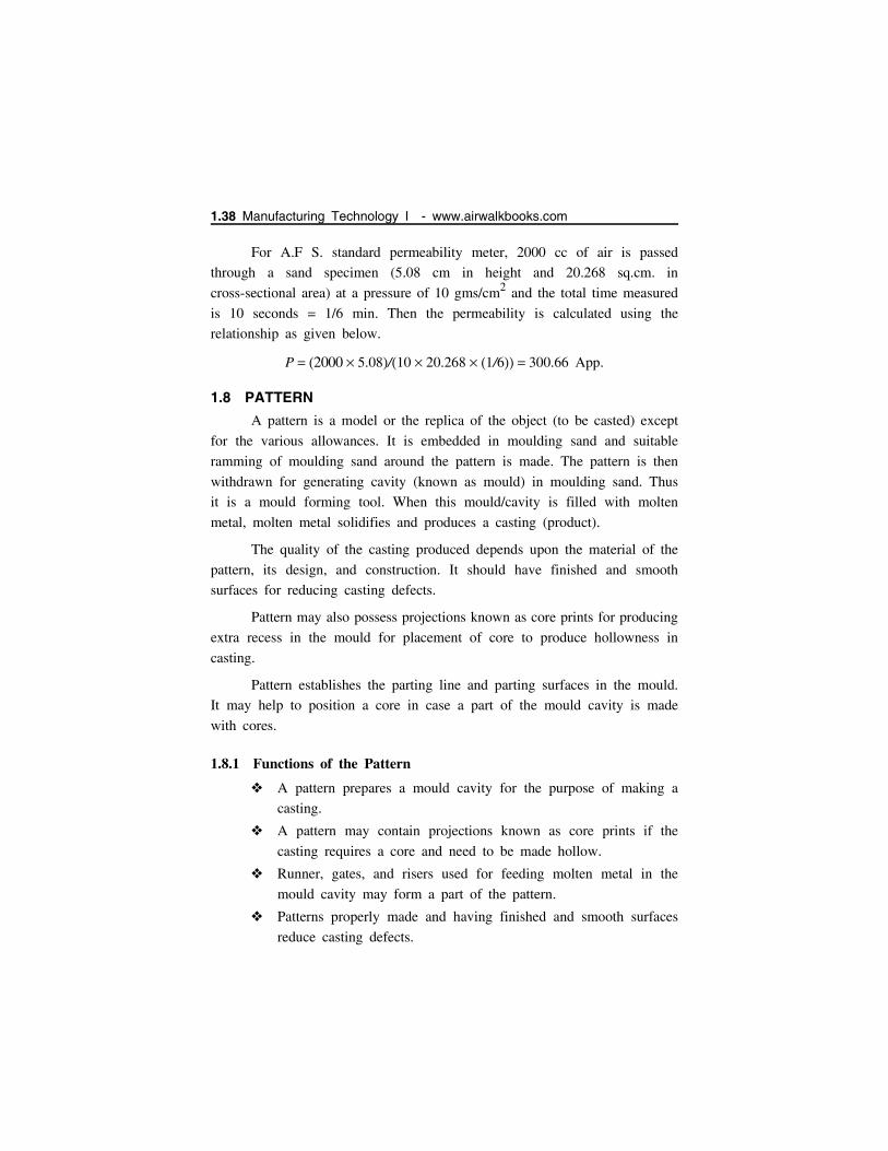
For A.F S. standard permeability meter, 2000 cc of air is passed
through a sand specimen (5.08 cm in height and 20.268 sq.cm. in
cross-sectional area) at a pressure of 10 gms/cm2 and the total time measured
is 10 seconds = 1/6 min. Then the permeability is calculated using the
relationship as given below.
P 2000 5.08/10 20.268 1/6 300.66 App.
1.8 PATTERN
A pattern is a model or the replica of the object (to be casted) except
for the various allowances. It is embedded in moulding sand and suitable
ramming of moulding sand around the pattern is made. The pattern is then
withdrawn for generating cavity (known as mould) in moulding sand. Thus
it is a mould forming tool. When this mould/cavity is filled with molten
metal, molten metal solidifies and produces a casting (product).
The quality of the casting produced depends upon the material of the
pattern, its design, and construction. It should have finished and smooth
surfaces for reducing casting defects.
Pattern may also possess projections known as core prints for producing
extra recess in the mould for placement of core to produce hollowness in
casting.
Pattern establishes the parting line and parting surfaces in the mould.
It may help to position a core in case a part of the mould cavity is made
with cores.
1.8.1 Functions of the Pattern
A pattern prepares a mould cavity for the purpose of making a
casting.
A pattern may contain projections known as core prints if the
casting requires a core and need to be made hollow.
Runner, gates, and risers used for feeding molten metal in the
mould cavity may form a part of the pattern.
Patterns properly made and having finished and smooth surfaces
reduce casting defects.
1.38 Manufacturing Technology I - www.airwalkbooks.com

A properly constructed pattern minimizes the overall cost of the
castings.
It establishes the parting line and parting surfaces in the mould.
1.8.2 TYPES OF PATTERN
The different types of pattern are given below
(a) One piece (or) solid pattern
Solid pattern is made of
single piece without joints,
parting lines or loose pieces.
It is the simplest form of the
pattern. Typical single piece
pattern is shown in
Fig. 1.13.
It is inexpensive and is used for making a few large sized simple
castings.
It is usually made of wood or metal depending upon number of
castings.
It is placed either in cope or drag.
Example: Stuffing box of Steam engine can be cast from single
piece pattern.
(b) Two piece (or) split pattern
Fig. 1.13. Single Piece Pattern.
Dowel holes
Dowel holes
Fig.1.14. Split P iece Pattern
Metal Casting Processes 1.39

Pattern of intricate shapes made by single piece pattern are difficult
to withdraw from the mould cavity, hence solid pattern is split
into two parts. Fig 1.14
Split pattern is made in two pieces which are joined at the parting
line by means of dowel pins.
The splitting at the parting line is done to facilitate the withdrawal
of the pattern.
One part is placed in cope & the other in drag
Example are taps, water stop cocks etc.,
(c) Loose piece pattern
Loose piece pattern (Fig. 1.15) is used when pattern is difficult for
withdrawal from the mould.
Loose pieces are provided on the pattern (E & F) and they are
attached to pattern by dowel pins.
The main pattern is removed first leaving the loose piece portion
of the pattern in the mould.
Finally the loose piece is withdrawn separately leaving the intricate
mould.
It requires more labour & is a time consuming process.
E F
M ain pattern
Dow elPins
Fig. 1.15 Loose Piece Pattern .
1.40 Manufacturing Technology I - www.airwalkbooks.com
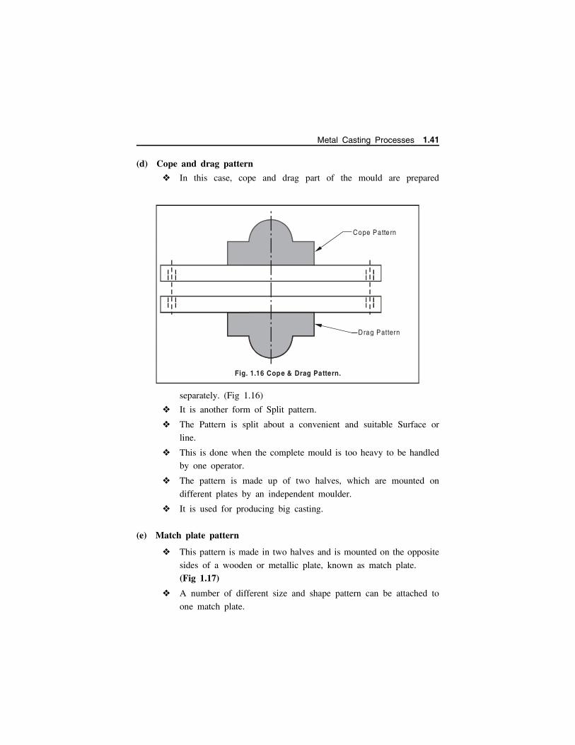
(d) Cope and drag pattern
In this case, cope and drag part of the mould are prepared
separately. (Fig 1.16)
It is another form of Split pattern.
The Pattern is split about a convenient and suitable Surface or
line.
This is done when the complete mould is too heavy to be handled
by one operator.
The pattern is made up of two halves, which are mounted on
different plates by an independent moulder.
It is used for producing big casting.
(e) Match plate pattern
This pattern is made in two halves and is mounted on the opposite
sides of a wooden or metallic plate, known as match plate.
(Fig 1.17)
A number of different size and shape pattern can be attached to
one match plate.
Cope Patte rn
Drag Pattern
Fig. 1.16 Cope & Drag Pattern.
Metal Casting Processes 1.41

The match plate is clamped to drag with the help of locator holes.
The gates and runners are also attached to the plate.
This pattern is used in machine moulding.
It is used to produce small casting in mass scale with high
accuracy and at faster rate.
Eg. Piston rings of IC – Engine
(f) Three-piece or multi- piece pattern
Some patterns are of complicated kind in shape and hence cannot be
made in one or two pieces because of difficulty in withdrawing the pattern.
Therefore these patterns are made in either three pieces or in multi-pieces.
Multi moulding flasks are needed to make mould from these patterns.
(Fig 1.18)
R unnerPa tte rns
M atch p la te
H o le fo r locating
Fig. 1.17 M atch P late Pattern
..
.
.
.. .
..
.
.
.. .
. . ..
. . .. .
..
.. ..
.... .
..
..
. ..
. .
..
.. . .
.. .
..
..
..
.
..
.
. .
..
.
..
.
.
.
... .
.
.
. .
..
. .
...
. .. ..
...
....
...
.
..
.
..
..
..
...
..
. ..
.. .
.
1
2
3
C heek
M ou ld ing BoxC ope
Pa rt/C ast
D rag
Fig. 1.18. Three Piece Pattern.
1.42 Manufacturing Technology I - www.airwalkbooks.com
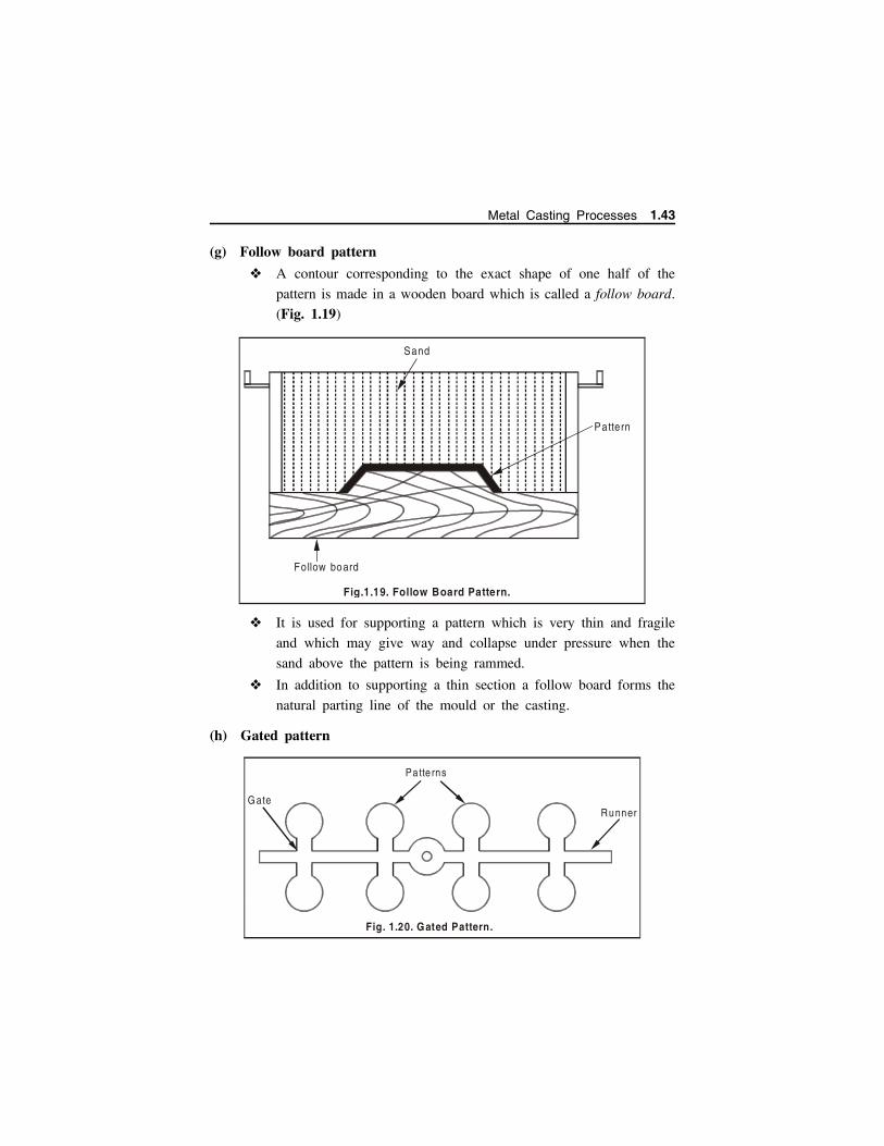
(g) Follow board pattern
A contour corresponding to the exact shape of one half of the
pattern is made in a wooden board which is called a follow board.
(Fig. 1.19)
It is used for supporting a pattern which is very thin and fragile
and which may give way and collapse under pressure when the
sand above the pattern is being rammed.
In addition to supporting a thin section a follow board forms the
natural parting line of the mould or the casting.
(h) Gated pattern
Sand
Pattern
Follow board
Fig.1.19. Follow Board Pattern.
G ate
Pa tte rns
Runner
Fig. 1.20. Gated Pattern.
Metal Casting Processes 1.43

In the mass production of castings, multi cavity moulds are used.
Such moulds are formed by joining a number of patterns and gates
and providing a common runner for the molten metal, as shown
in Fig. 1.20.
These patterns are made of metals and metallic pieces to form
gates and runners are attached to the pattern.
A gated casting produce many castings at one time and are used for
mass production of small castings.
(i) Sweep pattern
Sweep patterns are used for forming large circular moulds of
symmetric kind by revolving a sweep attached to a spindle as
shown in Fig. 1.21.
Actually a sweep is a template of wood or metal and is attached
to the spindle at one edge and the other edge has a contour
depending upon the desired shape of the mould.
The pivot end is attached to a stake of metal in the center of the mould.
A sweep pattern can be used for both green & dry sand moulding.
... ... ...
....... ... ...
....... ... ...
....... ... ...
....... ... .......
... ... ...
....... ... .. .
....
... ... .. .
....... ... ...
....... ... ...
....... ... ...
....
... ... ...
....... ... ...
....... ... ...
....... ... ...
....
... ... ...
....
... ... ...
....... ... ...
....... ... ...
....
... ... .......
... ... ...
....... ... ...
....... ... ...
....... ... ...
....
... ... .......
... ... ...
....... ... .. .
....
... ... .. .
....... ... ...
....... ... ...
....... ... .. .
....
... ... .. ........ ... ...
....... ... ...
....... ... ...
....
... ... ...
....... ... ...
.... ... ... .......
... ... .......
... ... .......... ... ...
....... ... ...
....
... ... .. .
....... ... ...
....
... ... ...
....... ... ...
....
... ... .......
... ... .......... ... ...
....... ... ...
....... ... ...
....... ... .. .
....
... ... ...
....
... ... .......
... ... .. .
....
... ... .......... ... ...
....
....... ..
... ........ ..
... ........ ..
... ........ ..
... . ....... ..... .
....... ..
... ........ ..
... .
....... ..
... ........ ..
... ........ ..
... ........ ..
... .
....... ..
... ........ ..
... ........ ..
... ........ ..
... .
....... ..
... .
....... ..
... ........ ..
... ........ ..
... .
....... ..... .
....... ..
... ........ ..
... ........ ..
... ........ ..
... .
....... ..... .
....... ..
... ........ ..
... .
....... ..
... ........ ..
... ........ ..
... ........ ..
... .
....... ..... . ....... ..
... ........ ..
... ........ ..
... .
....... ..
... ........ ..
... ........ ..... .
....... ..... .
....... ..... . ....... ..
... ........ ..
... .
....... ..
... ........ ..
... .
....... ..
... ........ ..
... .
....... ..... .
....... ..... . ....... ..
... . ....... ..
... ........ ..
... ........ ..
... .
....... ..
... .
....... ..... .
....... ..
... .
....... ..... ........ ..
... .
Po st
Sw e ep
G reen san d
Fig.1.21 S weep Pattern.
1.44 Manufacturing Technology I - www.airwalkbooks.com
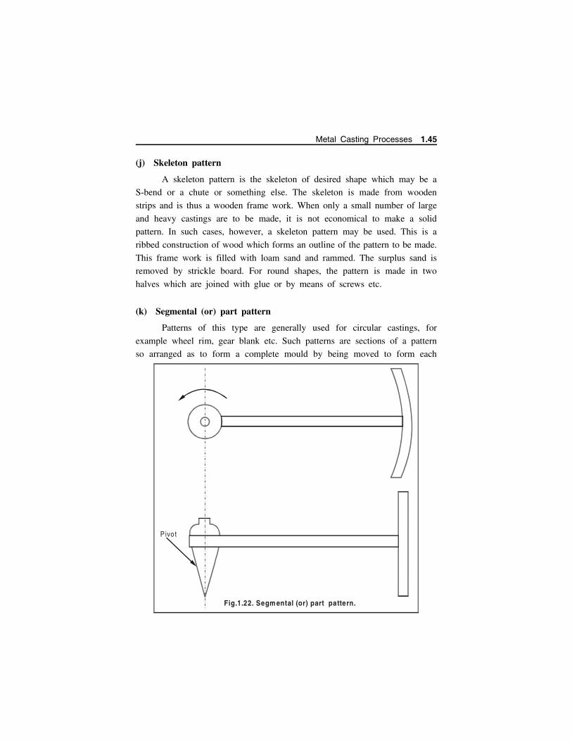
(j) Skeleton pattern
A skeleton pattern is the skeleton of desired shape which may be a
S-bend or a chute or something else. The skeleton is made from wooden
strips and is thus a wooden frame work. When only a small number of large
and heavy castings are to be made, it is not economical to make a solid
pattern. In such cases, however, a skeleton pattern may be used. This is a
ribbed construction of wood which forms an outline of the pattern to be made.
This frame work is filled with loam sand and rammed. The surplus sand is
removed by strickle board. For round shapes, the pattern is made in two
halves which are joined with glue or by means of screws etc.
(k) Segmental (or) part pattern
Patterns of this type are generally used for circular castings, for
example wheel rim, gear blank etc. Such patterns are sections of a pattern
so arranged as to form a complete mould by being moved to form each
Pivo t
Fig.1.22. Segm ental (or) part pattern.
Metal Casting Processes 1.45
section of the mould. The movement of segmental pattern is guided by the
use of a central pivot.
A segment pattern for a wheel rim is shown in Fig. 1.22.
1.8.3 Design Considerations for a good Pattern
A good pattern produces a sound casting and a poor pattern will
produces poor castings. The following are design considerations for a good
pattern.
A pattern should be accurate in its dimensions and posses very
good surface finish.
Proper material selection of pattern.
A pattern should carry all proper allowances.
In split pattern, parting surface should be such that maximum
portion of pattern is in drag.
All sharp edges and corners should be rounded.
Changes in the section thickness should be smooth, gradual and
uniform. It reduces stresses, strains and minimizes crack formation.
Type of Pattern selection should be proper.
Jointed core should be avoided to obtain uniform holes.
Core prints provided with pattern should be of optimum size and
suitably located.
All patterns for repeat orders should be coated with preservatives.
1.8.4 PATTERN MATERIALS
Patterns may be constructed from the following materials. Each
material has its own advantages, limitations, and field of application. Some
materials used for making patterns are: wood, metals and alloys, plastic,
plaster of Paris, plastic and rubbers, wax, and resins.
Wood
Wood is the most popular and commonly used material for pattern
making. The main varieties of woods used in pattern-making are shisham,
kail, deodar, teak and mahogany.
1.46 Manufacturing Technology I - www.airwalkbooks.com
Advantages of wooden patterns
Wood is cheap, easily available in abundance, repairable and easily
fabricated in various forms using resin and glues.
It is very light and can produce highly smooth surface.
It can preserve its surface by application of a shellac coating for
longer life of the pattern.
Disadvantages
Wood is susceptible to shrinkage and warpage and its life is short.
It is highly affected by moisture of the moulding sand.
After some use it warps and wears out quickly as it is having less
resistance to sand abrasion.
It cannot withstand rough handling and is weak in comparison to
metal.
Wooden patterns are preferred only when the number of castings
to be produced is less.
Metal Pattern
Metallic patterns are preferred when the number of castings required
is large. The wear and tear of this pattern is very less and hence posses
longer life. Metal pattern is easy to be shaped with good precision, surface
finish and intricacy in shapes. It can withstand against corrosion and handling
for longer period. It possesses excellent strength to weight ratio. These
patterns are not much affected by moisture of the sand. The main
disadvantages of metallic patterns are higher cost, higher weight and tendency
of rusting. The metals commonly used for pattern making are cast iron, brass
and bronzes and aluminum alloys.
Cast IronCast iron is cheaper, stronger, tough, and durable and can produce a
smooth surface finish. It also possesses good resistance to sand abrasion. The
drawbacks of cast iron patterns are that they are hard, heavy, brittle and get
rusted easily in presence of moisture.
Metal Casting Processes 1.47
Brasses and BronzesThese are heavier and expensive than cast iron and hence are preferred
for manufacturing small castings. They possess good strength, machinability
and resistance to corrosion and wear. They can produce a better surface finish.
Brass and bronze patterns are finding applications in making match plate
patterns.
Aluminum AlloysAluminum alloy patterns are more popular and best among all the
metallic patterns because of their high lightness, good surface finish, low
melting point and good strength. They also posses good resistance to corrosion
and abrasion by sand and there by enhancing longer life of pattern. These
materials do not withstand rough handling. They have poor repairability and
are preferred for making large castings.
Advantages
Aluminum alloy patterns do not rust.
They are easy to cast.
They are light in weight.
They can be easily machined.
Disadvantages
They can be damaged by sharp edges.
They are softer than brass and cast iron.
Their storing and transportation needs proper care.
White MetalWhite metal is an alloy of Antimony, Copper and Lead. It is best used
for lining and stripping plates. Its melting point is around 260C, it can be
cast into narrow cavities. The disadvantages of this white metal are that it is
too soft, it’s storing and transportation needs proper care and it wears away
by sand or sharp edges.
1.48 Manufacturing Technology I - www.airwalkbooks.com
Plastic
Patterns made of plastics materials are lighter, stronger, moisture and
wear resistant, non-sticky to moulding sand, durable and they are not affected
by the moisture of the moulding sand. Moreover they impart very smooth
surface finish on the pattern surface. These materials are somewhat fragile,
less resistant to sudden loading and their section may need metal
reinforcement. The plastics used for this purpose are thermosetting resins.
Phenolic resin plastics are commonly used. These are originally in liquid form
and get solidified when heated to a specified temperature. To prepare a plastic
pattern, a mould in two halves is prepared in plaster of paris with the help
of a wooden pattern known as a master pattern. The phenolic resin is poured
into the mould and the mould is subjected to heat. The resin solidifies giving
the plastic pattern. Recently a new material has stepped into the field of
plastic which is known as foam plastic.
Plaster
Plaster belongs to gypsum family which can be easily cast and
worked with wooden tools and preferable for producing highly
intricate casting.
The main advantages of plaster are that it has high compressive
strength and is of high expansion setting type which compensate
for the shrinkage allowance of the casting metal.
Plaster of paris pattern can be prepared either by directly pouring
the slurry of plaster and water in moulds prepared earlier from a
master pattern or by sweeping it into desired shape or form by
the sweep and strickle method.
It is also preferred for production of small size intricate castings
and making core boxes.
Wax
Wax patterns are excellent for investment casting process. The
materials used are blends of several types of waxes, and other
additives which act as polymerizing agents, stabilizers, etc.
Metal Casting Processes 1.49
The commonly used waxes are paraffin wax, shellac wax,
bees-wax, cerasin wax, and micro-crystalline wax.
The properties desired in a good wax pattern include low ash
content up to 0.05 per cent, resistant to the primary coat material
used for investment, high tensile strength and hardness, and
substantial weld strength.
Wax patterns are made by injecting liquid or semi-liquid wax into
a split die. Solid injection is also used to avoid shrinkage and for
better strength.
Wax use helps in imparting a high degree of surface finish and
dimensional accuracy of castings.
Wax patterns are prepared by pouring heated wax into split moulds
or a pair of dies. The dies after having been cooled down are
parted off. Now the wax pattern is taken out and used for
moulding.
Such patterns need not be drawn out solid from the mould. After
the mould is ready, the wax is poured out by heating the mould
and keeping it upside down.
Such patterns are generally used in the process of investment
casting where accuracy is linked with intricacy of the cast object.
1.8.5 Selection of pattern material
The following factors must be taken into consideration while selecting
pattern materials.
Number of castings to be produced. Metal patterns are preferred
when castings are required large in number.
Type of mould material used & type of moulding process.
Method of moulding (hand or machine).
Degree of dimensional accuracy, stability and surface finish
required.
Minimum thickness required.
Shape, complexity and size of casting.
1.50 Manufacturing Technology I - www.airwalkbooks.com
Resistance to wear and abrasion, resistance to corrosion, and to
chemical reactions
Low cost of production.
1.8.6 PATTERN ALLOWANCES
Pattern may be made from wood (or) metal and its size may not be
same as that of the casting. A pattern is always larger in size as compared
to the final casting because it carries allowances due to metallurgical reasons
(shrinkage on cooling) and mechanical reasons (machining, distortion, draft,
shake, sharp edges etc.,).
These various allowances given to pattern can be enumerated as,
allowance for shrinkage,
allowance for machining,
allowance for draft,
allowance for rapping or shake,
allowance for distortion and allowance for mould wall movement.
These allowances are discussed below.
(a) Shrinkage allowance
All common cast metals shrink a significant amount when they are
cooled from the molten state. The total contraction in volume is divided into
the following parts:
1. Liquid contraction, i.e. the contraction during the period in which the
temperature of the liquid metal or alloy falls from the pouring
temperature to the liquidus temperature.
2. Contraction on cooling from the liquidus to the solidus temperature, i.e.
solidifying contraction.
3. Solid contraction: Contraction that results there after until the
temperature reaches the room temperature.
The first two of the above are taken care of by proper gating and
risering. Only the last one, i.e. the solid contraction is taken care by the
pattern makers by giving a positive shrinkage allowance. This contraction
allowance is different for different metals.
Metal Casting Processes 1.51

The Shrinkage allowances for different metals and alloys are Cast
Iron-10 mm/mt, Brass-16 mm/mt, Aluminium Alloys-15 mm/mt, Steel- 21
mm/mt, Lead-24 mm/mt.
The Metal shrinkage depends upon the metal /alloy being casted,
Pouring temperature, Casting dimensions, Casting design aspects, Moulding
conditions (mould material and moulding methods).
(b) Machining allowance
Machining allowances is a positive allowance given to compensate for the
amount of material that is lost in machining or finishing the casting. If this
allowance is not given, the casting will become undersize after machining.
Machining allowance is given due to the following reasons:
1. Castings get oxidised inside mould and during heat treatment. Scale thus
formed requires to be removed.
2. For removing surface roughness, slag, dirt and other imperfections from
the casting.
3. For obtaining exact dimensions on the casting.
4. To achieve desired surface finish on the casting.
The amount of this allowance depends on
nature of metal,
the size and shape of casting,
methods of machining (grinding, turning milling boring etc.,),
casting condition,
moulding process involved,
number of cuts to be taken and the degree of finish.
In general, however, the value varies from 3 mm to 12 mm.
(c) Draft (or) Taper allowance
Taper allowance (Fig. 1.23) is also a positive allowance and is given
on all the vertical surfaces of pattern so that its withdrawal becomes easier.
The normal amount of taper on the external surfaces varies from 10 mm to
20 mm/mt. On interior holes and recesses which are smaller in size, the taper
should be around 60 mm/mt. These values are greatly affected by the size
1.52 Manufacturing Technology I - www.airwalkbooks.com
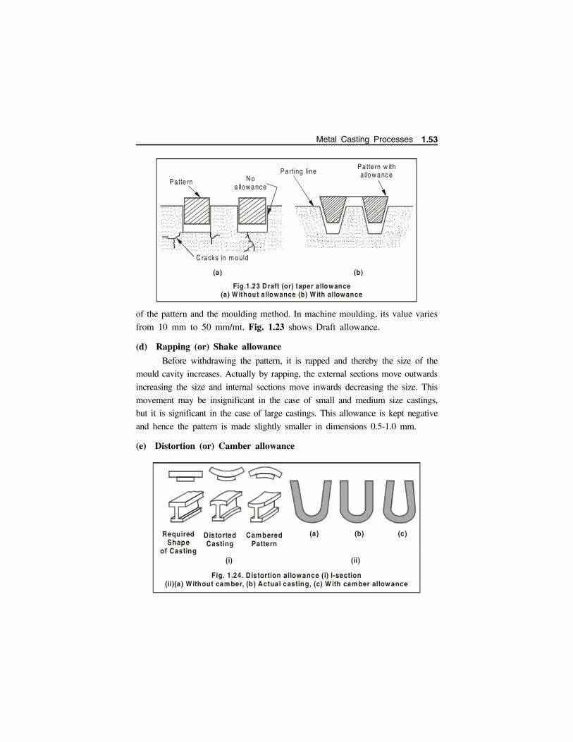
of the pattern and the moulding method. In machine moulding, its value varies
from 10 mm to 50 mm/mt. Fig. 1.23 shows Draft allowance.
(d) Rapping (or) Shake allowance
Before withdrawing the pattern, it is rapped and thereby the size of the
mould cavity increases. Actually by rapping, the external sections move outwards
increasing the size and internal sections move inwards decreasing the size. This
movement may be insignificant in the case of small and medium size castings,
but it is significant in the case of large castings. This allowance is kept negative
and hence the pattern is made slightly smaller in dimensions 0.5-1.0 mm.
(e) Distortion (or) Camber allowance
.. . . . . .....
.. . . . . ....... . . . . . ...... . . . . ....... . . . . ....... . . . . . ...... . . . . ....... . . . . ....... . . . . . ...... . . . . ....... . . . . ....... . . . . . ....
.. . . . . .....
.. . . . . ....... . . . . . ....
. . . . . . . ....
. . . . . . . ...... . . . . . ..... . . . . . . ....
. . . . . . . ...... . . . . . ....
. . . . . . . ....
. . . . . . . ...... . . . . . ....
.. . . . . . ....
.. . . . . . ...... . . . . . ....
. . . . . . . ....
. . . . . . . ...... . . . . . ....
. . . . . . . ....
. . . . . . . ...... . . . . . ....
.. . . . . . ....
.. . . . . . ...... . . . . .....
.. . . . . . ....
.. . . . . . ..... . . . . . . ....
. . . . . . . ....
. . . . . . . ...... . . . . . ....
.. . . . . . ....
.. . . . . . ..... . . . . . . ....
...
...
.. ..
...
...
... .
.. ...
...
.. ..
.
..... .
. ..
..
. .... .
. ..
..
. .... .
. ..
..
. . .. . .
. ..
..
. . .. . .
. ..
..
. . .. . .
. ..
..
.. . ... ..
..... . . . . . ..... . . . . . . ....
. .. . . . . ....
. . . . . . . ...... . . . . . ....
.. . . . .
.....
.. . . . .
.
.
..... . . . .
.
.
...
Pa tte rn N o a llow ance
Pa tte rn w ith a llow anceParting line
C racks in m ould
(a) (b)
Fig.1.23 D raft (or) taper allowance (a) W ithout a llowance (b) W ith allowance
Required Shape
of Casting
DistortedCasting
CamberedPattern
(i)
(a) (b) (c)
(ii)
Fig. 1.24. Distortion allowance (i) I-section(ii)(a) Without cam ber, (b) Actual casting, (c) W ith cam ber allowance
Metal Casting Processes 1.53

This allowance is applied to the castings which have the tendency to
distort during cooling due to thermal stresses developed. For example a
casting in the form of U shape will contract at the closed end on cooling,
while the open end will remain fixed in position. Therefore, to avoid the
distortion, the legs of U pattern must converge slightly so that the sides will
remain parallel after cooling. Another example is I shaped channel where to
avoid distortion cambered is given (Fig 1.24)
(f) Mould wall movement allowance
Mould wall movement in sand moulds occurs as a result of heat and
static pressure on the surface layer of sand at the mould metal interface. In
ferrous castings, it is also due to expansion due to graphitization. This
enlargement in the mould cavity depends upon the mould density and mould
composition. This effect becomes more pronounced with increase in moisture
content and temperature.
1.9 CORES
Cores are compact mass of core sand prepared separately, when placed
in mould cavity at required location. It does not allow the molten metal to
occupy space for solidification in that portion and hence help to produce
hollowness in the casting. The environment in which the core is placed is
much different from that of the mould. In fact the core has to withstand the
severe action of hot metal which completely surrounds it.
1.9.1 Functions (or) Objectives of core
Core produces hollowness in castings in the form of internal
cavities.
It must be sufficiently permeable to allow the easy escape of gases
during pouring and solidification.
It may form a part of green sand mould.
It may provide external undercut features in casting.
It may be inserted to achieve deep recess in the casting.
It may be used to strengthen the mould.
It may be used to form gating system of large size mould.
1.54 Manufacturing Technology I - www.airwalkbooks.com
1.9.2 Core Sand
Core Sand is a special kind of moulding sand. The main constituents
of the core sand are pure silica sand and a binder. Silica sand is preferred
because of its high refractoriness. For higher values of permeability, sands
with coarse grain size distribution are used. The main purpose of the core
binder is to hold the grains together, impart strength and sufficient degree of
collapsibility. Beside these properties needed in the core sand, the binder
should be such that it produces minimum amount of gases when the molten
metal is poured in the mould. Although, in general the binders are inorganic
as well as organic, but for core making, organic binders are generally preferred
because they are combustible and can be destroyed by heat at higher
temperatures thereby giving sufficient collapsibility to the core sand.
1.9.3 Considerations in Selecting Core Sand
Keeping above mentioned objectives in view, the special considerations
should be given while selecting core sand. These considerations involve
The cores are subjected to a very high temperature and hence the
core sand should be highly refractory in nature.
The permeability of the core sand must be sufficiently high as
compared to that of the moulding sands so as to allow the core
gases to escape through the limited area of the core recesses
generated by core prints.
The core sand should not possess such materials which may
produce gases while they come in contact with molten metal and
The core sand should be collapsible in nature, i.e. it should
disintegrate after the metal solidifies, because this property will
ease the cleaning of the casting.
1.9.4 Binders for core sand
The common binders which are used in making core sand are as
follows:
Metal Casting Processes 1.55
(a) Cereal binderIt develops green strength, baked strength and collapsibility in core.
The amount of these binders used varies from 0.2 to 2.2% by weight in the
core sand.
(b) Protein binderIt is generally used to increase collapsibility property of core.
(c) Thermosetting resinThermosetting resins are popular because, it imparts high strength,
collapsibility to core sand and it also evolves minimum amount of mould and
core gases which may produce defects in the casting. The most common
binders under this group are phenol formaldehyde and urea formaldehyde.
(d) Sulphite binderSulphite binder is also sometimes used in core but along with certain
amount of clay.
(e) DextrinDextrin is commonly added to core sand for increasing collapsibility
and baked strength of core.
(f) PitchPitch is widely used to increase the hot strength of the core.
(g) MolassesMolasses is generally used as a secondary binder to increase the
hardness on baking. It is used in the form of molasses liquid and is sprayed
on the cores before baking.
(h) Core oilCore oil in liquid state, when it is mixed with the core sand, forms a
coherent solid film holding the sand grains together when it is baked.
1.9.5 Core Making
Stages in core making
Core making basically is carried out in five stages namely
Core Sand Preparation,
Core Making,
1.56 Manufacturing Technology I - www.airwalkbooks.com
Core Baking
Core Finishing
Setting the cores
(a) Core Sand Preparation Preparation of core to get better and uniform core sand properties,
satisfactory and homogenous mixture of core using proper sand
constituents and additives, the core sands are generally mixed with
the help of any of the following mechanical means namely roller
mills, core sand mixer using vertical revolving arm type and
horizontal paddle type mechanisms. These machines perform the
mixing of core sand constituents most thoroughly.
(b) Core Making Process Small cores are made manually in hand rammed core boxes.
Cores on mass scale are rapidly produced on a variety of core
making machines – to name a few core blowing, core ramming
and core extrusion machines
I. Hand making of coresSmall sized cores for limited production are made manually in hand
filled core boxes. The steps involved in making core by hand are:
Place the core box on work bench and it is filled with the already
mixed and prepared core sand and rammed by hand and the extra sand
is removed. (weak cores are reinforced using steel wires).
Core box is inverted over the core plate to transfer the core to
the plate.
It is then baked in oven for specified period and then removed
and cooled. Now the core is ready.
II. Core making machines
(i) Core blowing machines The basic principle of core blowing machine comprises of filling
the core sand into the core box by using compressed air (at 5 to
7 bar pressure). (Fig 1.25)
Metal Casting Processes 1.57
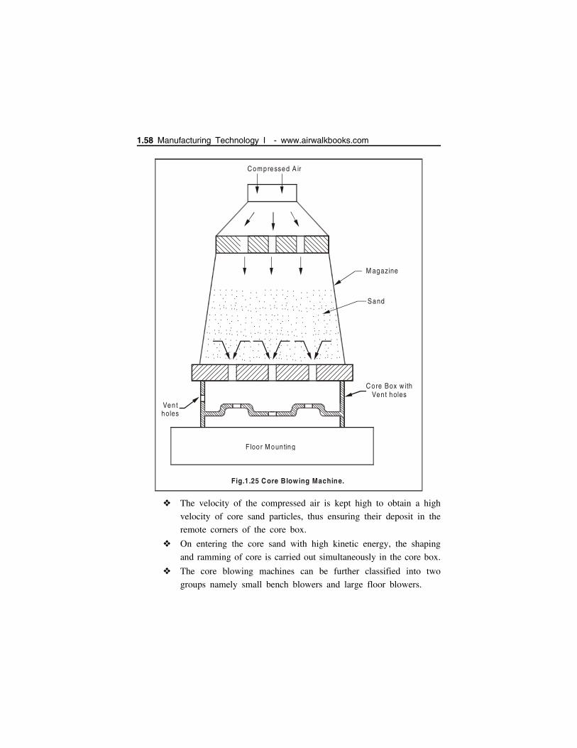
The velocity of the compressed air is kept high to obtain a high
velocity of core sand particles, thus ensuring their deposit in the
remote corners of the core box.
On entering the core sand with high kinetic energy, the shaping
and ramming of core is carried out simultaneously in the core box.
The core blowing machines can be further classified into two
groups namely small bench blowers and large floor blowers.
.
.
... .
..
.
.
.
..
... .
..
.
.
...
... .
..
.
.
...
... .
..
.
.
.
.
.
...
.
..
.
.
.
.
.
.
... .
..
.
.
...
... .
..
.
.
...
... .
..
.
.
.
.
.
... .
..
.
.
.
.
.
... .
..
.
.
...
... .
..
.
.
...
... .
..
.
.
.
.
.
...
.
..
.
.
.
.
.
.
... .
..
.
.
...
... .
..
.
.
...
... .
..
.
.
.
.
.
... .
..
.
.
.
..
... .
..
.
.
...
... .
..
.
.
...
... .
..
.
.
.
..
...
.
..
.
.
.
.
.
.
... .
..
.
.
...
... .
..
.
.
...
... .
..
.
.
.
.
.
.. ..
..
.
.
.
..
.. .
.
.
.
.
..
.. ..
..
.
.
.
.
.
.. ..
..
.
.
...
.. .
.
.
.. ..
..
.
.
.
.
.
.. ..
..
.
.
...
.. .
Ven tholes
M agazine
Sand
Core Box w ithVent holes
Floor M ounting
Compressed A ir
Fig.1.25 C ore Blowing Machine.
1.58 Manufacturing Technology I - www.airwalkbooks.com

Small bench blowers are quite economical for core making shops
having low production and are bench type.
Big core blowing machines are either vertical or horizontal floor
mounted type.
The cartridge oriented sand magazine is considered to be a part of
the core box equipment.
However, one cartridge may be used for several boxes of
approximately the same size. The cartridge is filled using hands.
Then the core box and cartridge are placed in the machine for
blowing and the right handle of the machine clamps the box and
the left handle blows the core.
(ii) Core drawing/extrusion machines Uniform cross section and regular simple cores are extruded by
core extrusion machine.
Cores of square, round, hexagonal and oval section are widely
produced by core extrusion machine.
Fig 1.26 shows a core extrusion machine which consists of hopper
through which core sand is fed to horizontal spiral conveyor. As
the spiral conveyor is rotated it forces core sand through a die of
specified shape (square, round etc.,)
..
.
..
.
..
.
..
.
..
..
..
.
..
. . . . .
. . . . . . . . . . . ..
..
. . . . .
. . . . . . . . . . . ..
..
. . . . .
. . . . . . . . . . . .
..
.
..
.
..
.
..
.
..
.
..
.
..
.
..
.
..
.
..
.
...
...
...
...
...
...
...
...
...
...
...
...
...
. . .. . .
..
.
...
..
.
...
..
.
..
.
...
..
..
..
..
.
...
...
...
. . . .. . .
.
D ie
Sp ira l conveyor
Core Sand
Hopper
Power or Hand Driven
Core out
Bench
Fig.1.26 C ore Extrusion machine.
.
Metal Casting Processes 1.59
Long cores thus produced can be cut to the desired length.
The drawn core is then baked further before its use in mould cavity
to produce hollowness in the casting.
(iii) Core ramming machinesCores can also be prepared by ramming core sands in the core boxes
by machines based on the principles of squeezing, jolting and slinging. Out
of these three machines, jolting and slinging are more common for core
making.
(c) Core Baking Once the cores are prepared, they will be baked in baking ovens
or furnaces.
The main purpose of baking is to drive away the moisture and
harden the binder, thereby giving strength to the core. Core are
baked upto 380C. Core baking develops the properties of organic
binders.
At 100C moisture is driven out and at 125C to 225C Core oil
and other organic binders change chemically and molecularly from
liquid to solid state.
The core drying equipments are usually of two kinds namely core
ovens and dielectric bakers.
The core ovens are of two types namely continuous type oven and
batch type oven.
Continuous type ovens: Continuous type ovens are preferred
basically for mass production. In these types, core carrying
conveyors or chain move continuously through the oven. The
baking time is controlled by the speed of the conveyor. The
continuous type ovens are generally used for baking of small cores.
Batch type ovens: Batch type ovens are mainly utilized for baking
variety of cores in batches. The cores are commonly placed either
in drawers or in racks which are finally placed in the ovens. The
core ovens and dielectric bakers are usually fired with gas, oil or
coal.
1.60 Manufacturing Technology I - www.airwalkbooks.com
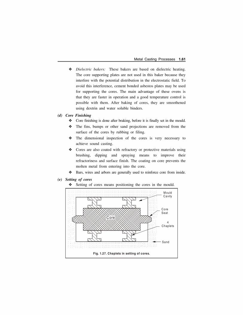
Dielectric bakers: These bakers are based on dielectric heating.
The core supporting plates are not used in this baker because they
interfere with the potential distribution in the electrostatic field. To
avoid this interference, cement bonded asbestos plates may be used
for supporting the cores. The main advantage of these ovens is
that they are faster in operation and a good temperature control is
possible with them. After baking of cores, they are smoothened
using dextrin and water soluble binders.
(d) Core Finishing Core finishing is done after braking, before it is finally set in the mould.
The fins, bumps or other sand projections are removed from the
surface of the cores by rubbing or filing.
The dimensional inspection of the cores is very necessary to
achieve sound casting.
Cores are also coated with refractory or protective materials using
brushing, dipping and spraying means to improve their
refractoriness and surface finish. The coating on core prevents the
molten metal from entering into the core.
Bars, wires and arbors are generally used to reinforce core from inside.
(e) Setting of cores Setting of cores means positioning the cores in the mould.
.
.
.
.
.
.
.
.
.
.
.
.
.
.
.
.
.
.
.
.
.
.
.
.
.
.
.
.
.
.
.
.
.
.
.
.
.
.
.
.
.
.
.
.
.
.
.
.
.
.
.
.
.
.
.
.
.
.
.
.
.
.
.
.
.
.
.
.
.
.
.
.
.
.
.
.
.
.
.
.
.
.
.
.
.
.
.
.
.
.
.
.
.
.
.
.
.
.
.
.
.
.
.
.
.
.
.
.
.
.
.
.
.
.
.
.
.
.
.
.
.
.
.
.
.
.
.
.
.
.
.
.
.
.
.
.
.
.
.
.
.
.
.
.
.
.
.
.
.
.
.
.
.
.
.
.
.
.
.
.
.
.
.
.
.
.
.
.
.
.....
.
.
.
.
.
.
.
.
.
.
.
.
.
.
.
.
.
.
.
.
.
.
.
.
.
.
.
. . . . . . . . . .
. .
.. . . . . . . . . .
..
. . . . . . . . . . . .. . . . . . . . . . . .
. . . . . . . . . . . .. . . . . . . . . . . .
. . . . . . . . . . . .. . . . . . . . . . . .
. . . . . . . . .
.
.
.. . . . . . . . .
.. .
. . . . . . . . . . . .. . . . . . . . . . . .
. . . . . . . . . . . .. . . . . . . . . . . .
. . . . . . . . . . . .. . . . . . . . . . . .
.
.
.
.
.
.
.
.
.
.
.
.
.
. . . . . . . . . .
.
.. . . . . . . . .
.. .
. . . . . . . . . . . .. . . . . . . . . . . .
. . . . . . . . . . . .. . . . . . . . . . . .
. . . . . . . . . . . .. . . . . . . . . . . .
.
.
.
.
.
.
.
.
.
.
.
.
.
.
.
.
.
.
.
.
.
.
.
.
.
.
.
.
.
.
.
.
.
.
.
.
.
.
.
.
.
.
.
.
.
.
.
.
.
.
.
.
.
.
.
.
.
.
.
.
.
.
.
.
.
.
.
.
.
.
.
.
.
.
.
.
.
.
.
.
.
.
.
.
.
.
.
.
.
.
.
.
.
.
.
.
.
.
.
.
.
.
.
.
.
.
.
.
.
.
.
.
.
.
.
.
.
.
.
.
.
.
.
.
.
.
.
.
.
.
.
.
.
.
.
.
.
.
.
.
.
.
.
.
.
.
.
.
.
.
.
.
.
.
.
.
.
.
.
.
.
.
.
.
.
.
.
.
.
.
.
.
.
.
.
.
.
.
.
.
.
.
.
.
.
.
.
.
M ouldCavity
Core Seat
4Chap le ts
Sand
Fig. 1.27. Chaplets in setting of cores.
Core
.
.
.
.
.
.
.
.
.
.
.
.
.
.
.
.
.
.
.
.
.
.
.
.
.
.
.
.
.
.
.
.
.
.
.
.
.
.
.
.
.
.
.
.
...
.
.
.
.
.
.
.
.
.
.
.
.
.
.
.
.....
.
.
.
.
.
.
.
.
.
.
.
.
.
.
.
.
.
.
.
.
.
.
.
.
.
.
.
.
.
.
.
.
.
.
.
.
.
.
.
.
.
.
.
.
.
.
.
.
.
.
.
.
.
.
.
.
.
.
.
.
.
.
.
.
.
.
.
.
.
.
.
.
.
.
.
.
.
.
.
.
.
.
.
.
.
.
.
.
.
.
.
.
.
.
.
.
.
.
.
.
.
.
.
.
.
.
.
.
.
.
.
.
.
.
.
.
.
...
.
...
Metal Casting Processes 1.61

In order to obtain correct cavities in the casting the cores must be
accurately positioned.
Core in mould should be firmly secured so that they can withstand
the buoyancy effect of the molten metal poured.
Small cores are set by hand while large ones by crane.
Cores are supported by chaplets to avoid sagging, shifting or
sinking of the cores.
Chaplets are metal shapes which are positioned between mould
and core surfaces. Chaplets are made of the same materials as that
of the cast. Fig. 1.27.
Various forms of chaplets are commercially available.
1.9.6 TYPES OF CORES AND APPLICATIONS
Cores are classified according to
(a) State (or) Condition of core
Green sand core and Dry sand core.
(b) Nature of core materials employed
Oil bonded core, Resin bonded core, Shell core and Sodium silicate
core.
(c) Type of core hardening process employed
CO2 Process, Hot box core, cold set process, Oil – No-Bake core
(d) Shape and position of core
Horizontal core, Vertical core, Hanging core, Balanced core, Drop core
(i) Green Sand Cores Green sand cores are made by green sand containing moist
condition about 5% water and 15- 30 % clay.
It imparts very good permeability to core and thus avoids defects
like shrinkage or voids in the casting.
They are used in green condition and are generally preferred for
simple, small and medium castings.
1.62 Manufacturing Technology I - www.airwalkbooks.com
Such cores possess less strength in comparison to dry sand cores
and hence cannot be stored for longer period.
(ii) Dry Sand Cores Dry sand cores are produced by drying the green sand cores to
about 110C.
These cores possess high strength rigidity and also good thermal stability.
These cores can be stored for long period and are more stable
than green sand core.
They are used for large castings.
They also produce good surface finish in comparison to green sand
cores.
They can be handled more easily. They resist metal erosion.
These types of cores require more floor space, more core material,
high labour cost and extra operational equipment.
(iii) Oil bonded coresSand cores are produced by mixing silica sand with small percentage
of linseed oil. Oil bonded cores are based on the principle of Oxidation and
Polymerisation of oils containing chemical additives which can be activated
by an oxygen bearing material set in a predetermined time.
(iv) Shell CoreShell cores are made as follows: The core box is heated to a
temperature of around 400C to 600C. Sand mixed with 2-5 % of thermosetting
resin (Phenolic type) is dumped / blown to the above heated core box. The resin
is allowed to melt to the specified thickness. The resin gets cured. The excess
sand is removed. The hardened core is extracted from box and does not require
further baking.
Shell core possess very smooth surfaces and very close tolerances. High
permeability is achieved in shell cores. They can be easily stored and are
very costly.
Metal Casting Processes 1.63
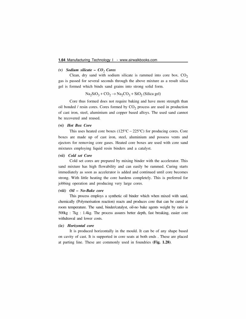
(v) Sodium silicate – CO2 CoresClean, dry sand with sodium silicate is rammed into core box. CO2
gas is passed for several seconds through the above mixture as a result silica
gel is formed which binds sand grains into strong solid form.
Na2SiO3 CO2 Na2CO3 SiO2 Silica gel
Core thus formed does not require baking and have more strength than
oil bonded / resin cores. Cores formed by CO2 process are used in production
of cast iron, steel, aluminium and copper based alloys. The used sand cannot
be recovered and reused.
(vi) Hot Box CoreThis uses heated core boxes (125C 225C) for producing cores. Core
boxes are made up of cast iron, steel, aluminium and possess vents and
ejectors for removing core gases. Heated core boxes are used with core sand
mixtures employing liquid resin binders and a catalyst.
(vii) Cold set CoreCold set cores are prepared by mixing binder with the accelerator. This
sand mixture has high flowability and can easily be rammed. Curing starts
immediately as soon as accelerator is added and continued until core becomes
strong. With little heating the core hardens completely. This is preferred for
jobbing operation and producing very large cores.
(viii) Oil – No-Bake coreThis process employs a synthetic oil binder which when mixed with sand,
chemically (Polymerisation reaction) reacts and produces core that can be cured at
room temperature. The sand, binder/catalyst, oil-no bake agents weight by ratio is
500kg : 7kg : 1.4kg. The process assures better depth, fast breaking, easier core
withdrawal and lower costs.
(ix) Horizontal coreIt is produced horizontally in the mould. It can be of any shape based
on cavity of cast. It is supported in core seats at both ends . These are placed
at parting line. These are commonly used in foundries (Fig. 1.28).
1.64 Manufacturing Technology I - www.airwalkbooks.com
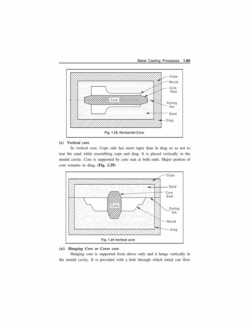
(x) Vertical coreIn vertical core, Cope side has more taper than in drag so as not to
tear the sand while assembling cope and drag. It is placed vertically in the
mould cavity. Core is supported by core seat at both ends. Major portion of
core remains in drag. (Fig. 1.29)
(xi) Hanging Core or Cover coreHanging core is supported from above only and it hangs vertically in
the mould cavity. It is provided with a hole through which metal can flow
.
.. . .
..
. . .. . .
..
. .
.. . .
..
. . .. . .
..
. .
.. . .
..
. . .. . .
..
. . .. . .
..
. . .. . .
..
. . .. . .
..
. . .. . .
..
. . .. . .
..
. . .. . .
..
. . .. . .
..
. . .. . .
..
. ... . .
..
. . .. . .
..
. ... . .
..
. . .. . .
..
. ... . .
..
. . .. . .
..
. . .. . .
..
. .
.. . .
..
. . .. . .
..
. . .. . .
..
. . .. . .
..
. . .. . .
..
. ... . .
..
. . .. . .
..
. ... . .
..
. . .. . .
..
. ... . .
..
. . .. . .
..
. . .. . .
..
. ... . .
..
. . .. . .
..
. . .. . .
..
. .
.. . .
..
. ..
. . ..
.. .
.. . .
..
. ... . .
..
. ..
. . ..
.. .
.. . .
..
. .
.. . .
..
. . .. . .
..
. ... . .
..
. .
.. . .
..
. . .. . .
..
. .
.. . .
..
. . .. . .
..
. .
.. . .
..
. . .. . .
..
. .
.. . .
..
. . .. . .
..
. .
.. . .
..
. ... . .
..
. ... . .
..
. ... . .
..
. .
.. . .
..
. . .. . .
..
. . .. . .
..
. . .. . .
..
. . .. . .
..
. . .. . .
..
. . .. . .
..
. . .. . .
..
. . .. . .
..
. . .. . .
..
. . .. . .
..
. . .. . .
..
. . .. . .
..
. . .. . .
..
. . .. . .
..
. . .. . .
..
. . .. . .
..
. . .. . .
..
. . .. . .
..
. . .. . .
..
. .
.. . .
..
. . .. . .
..
. . .. . .
..
. . .. . .
..
. . .. . .
..
. . .. . .
..
. .
Co re
Co pe
M ou ld
Co re S eat
Pa rting line
Sa nd
Dra g
Fig. 1.28. Horizontal Core.
.. . .
..
. .
.. . .
..
. .
.. . .
..
. .
.. . .
..
. .
.. . .
..
. .
.. . .
..
. ... . .
..
. .
.. . .
..
. .
.. . .
..
. .
.. . .
..
. . .. . .
..
. .
.. ....
..
.. . .
..
. ... . ....
.
.. . .
..
. .
.. . .
..
. ..
. . ..
.. .
.. . .
..
. .
.. . .
..
. .
.. . .
..
. ..
. . ..
.. .
.. . .
..
. .
.
.. .
..
. .
.. . .
..
. ..
. . ..
.. .
.. . .
..
. ... . .
..
. .
.. . .
..
. . .. . .
..
. .
.. . .
..
. ... . .
..
. .
.. . .
..
. ..
. . ..
.. .
.. . .
..
. ... . .
..
. .
.. . .
..
. . .. . .
..
. .
.. . .
..
. ... . .
..
. ... . .
..
. ... . .
..
. .
.. . .
..
. . .. . .
..
. .
.. . .
..
. . .. . .
..
. . .. . .
..
. . .. . .
..
. . .. . .
..
. . .. . .
..
. . .. . .
..
. . .. . .
..
. . .. . .
..
. . .. . .
..
. . .. . .
..
. . .. . .
..
. .
.. . .
..
. ... . .
..
. . .. . .
..
. . .. . .
..
. . .. . .
..
. .
.. . .
..
. .
.. . .
..
. .
.. . ...
...
. . ..
.. ..
. . ..
.. . .
. . ..
.. .
C ore
C ope
M ou ld
C ore S eat
Sand
Parting line
D ra g
Fig. 1.29 Vertical core
.. . .
..
. ... . .
..
. ... . .
..
. ... . .
..
. ... . .
..
. ... . .
..
. ... . ....
.
.. . ....
.
.. . .
..
. .
.. . .
..
. .
. ... . ..
.
. ... . ..
.. ... . ..
.
. ... . ..
.
. ... . ..
.
. ... . ..
.. ... . ..
.
. ... . ..
.
. ... . ..
.. ... . ..
.
. ... . ..
.. ... . ..
. . ... . ..
.. ... . ..
.
. ... . ..
.
. ... . ..
.
. ... . ..
.
. ... . ..
.. ... . ..
. . ... . ..
.. ... . ..
.
. ... . ..
.
. ... . ..
.. ... . ..
.
. ... . ..
.
. ... . ..
. . ... . ..
.
. ... . ..
.
. ... . ..
.
. ... . ..
.
. ... . ..
.
. ... . ..
.. ... . ..
. . ..
. ...
. . ..
. ...
.
. ... . ..
.
. ... . ..
.
Metal Casting Processes 1.65
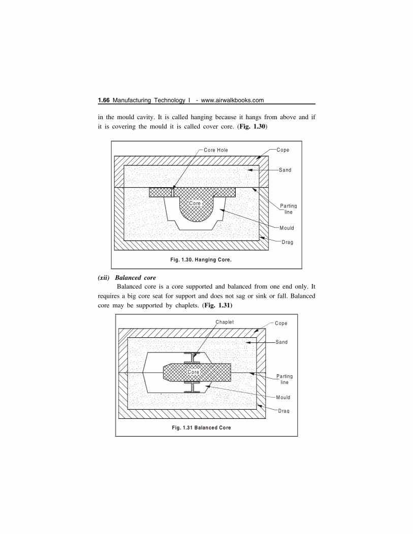
in the mould cavity. It is called hanging because it hangs from above and if
it is covering the mould it is called cover core. (Fig. 1.30)
(xii) Balanced coreBalanced core is a core supported and balanced from one end only. It
requires a big core seat for support and does not sag or sink or fall. Balanced
core may be supported by chaplets. (Fig. 1.31)
.
.. . .
..
. . .. . .
..
. .
.. . .
..
. .
.. . .
..
. .
.. . .
..
. . .. . .
..
. . .. . .
..
. . .. . .
..
. . .. . .
..
. . .. . .
..
. . .. . .
..
. . .. . .
..
. . .. . .
..
. . .. . .
..
. ... . .
..
. . .. . .
..
. ... . .
..
. . .. . .
..
. ... . .
..
. . .. . .
..
. . .. . .
..
. ..
. . ..
.. . .
. . ..
.. . .
. . ..
.. ..
. . ....
. .. . .
..
. . .. . .
..
. . .. . .
..
. ... . .
..
. . .. . .
..
. . .. . .
..
. .
.. . .
..
. .
.. . .
..
. . .. . .
..
. .
.. . .
..
. ..
. . ..
.. .
.. . .
..
. ..
. . ..
.. .
.. . .
..
. . .. . .
..
. . .. . .
..
. . .. . .
..
. . .. . .
..
. . .. . .
..
. . .. . .
..
. . .. . .
..
. . .. . .
..
. . .. . .
..
. . .. . .
..
. ... . .
..
. . .. . .
..
. . .. . .
..
. ... . .
..
. ... . .
..
. . .. . .
..
. ... . .
..
. .
.. . .
..
. .
.. . .
..
. .
.. . .
..
. . .. . .
..
. ..
. . ..
.. .
C ope
M ou ld
Parting line
Sand
D rag
Fig. 1.31 Balanced Core
.. . .
..
. ... . .
..
. ... . .
..
. .
.. . .
..
. ... . .
..
. .
.. . .
..
. ... . .
..
. . .. . .
..
. .
.. . .
..
. .
.. . .
..
. ... . .
..
. . .. . .
..
. . .. . .
..
. ... . .
..
. ... . .
..
. .
.. . .
..
. .
.. . .
..
. .
. ..
. ...
.
.. . .
..
. ... . .
..
. ... . .
..
. .
.. . .
..
. . .. . .
..
. ... . .
..
. .
.. . .
..
. ... . .
..
. .
.. . .
..
. .
.. . .
..
. ... . .
..
. ... . .
..
. .
.. . .
..
. . .. . .
..
. . .. . .
..
. .
.. . .
..
. ... . ....
.
.. . .
..
. ... . .
..
. ....
..
..
... . .
..
. .
.. . .
..
. .
C o re
..
.. .
... .
..
. ...
. ..
.. .
... .
..
. ...
. ..
.. .
... .
..
. ...
. ..
.. .
... .
..
. ...
.
..
..
...
. ..
..
...
...
..
...
. ..
..
...
.
..
.. .
... .
..
. ...
.
..
.. .
... .
..
. ...
.
....
..
......
..
..
....
..
......
..
......
..
...
....
...
....
..
......
..
......
..
..
....
..
...
....
...
....
..
..
....
..
..
....
..
..
....
..
......
..
......
..
......
..
..
....
..
......
..
......
..
......
..
..
....
..
.. ....
..
.. ....
..
..
....
..
......
..
... ... . ..
.
....
..
..
....
..
...
....
... .
....
...
....
..
......
..
..
....
..
..
....
..
..
....
..
......
..
..
....
..
..
....
..
......
..
..
....
..
..
....
..
..
. ... . .
..
.. . .
..
. .
.. . .
..
. .
.. . .
..
. .
.. ...
. ..
.. . .
..
. .
.. . .
..
. .
C hap le t
.
.. . .
..
. . .. . .
..
. .
.. . .
..
. .
.. . .
..
. .
.. . .
..
. . .. . .
..
. . .. . .
..
. . .. . .
..
. . .. . .
..
. . .. . .
..
. . .. . .
..
. . .. . .
..
. . .. . .
..
. . .. . .
..
. ... . .
..
. . .. . .
..
. ... . .
..
. . .. . .
..
. ... . .
..
. . .. . .
..
. . .. . .
..
. .
.. . .
..
. . .. . .
..
. . .. . .
..
. . .. . .
..
. . .. . .
..
. ... . .
..
. . .. . .
..
. ... . .
..
. . .. . .
..
. ... . .
..
. . .. . .
..
. . .. . .
..
. .
.. . .
..
. .
.. . .
..
. . .. . .
..
. .
.. . .
..
. ... . .
..
. ..
. . ..
.. .
.. . .
..
. .
.. . .
..
. . .. . .
..
. . .. . .
..
. . .. . .
..
. . .. . .
..
. . .. . .
..
. . .. . .
..
. . .. . .
..
. . .. . .
..
. . .. . .
..
. . .. . .
..
. ..
. . ..
.. . .
. . ..
.. . .
. . ..
.. .
.. . .
..
. ... . .
..
. . .. . .
..
. ... . .
..
. .
.. . .
..
. .
.. . .
..
. .
.. . .
..
. . .. . .
..
. ..
. . ..
.. .
Cope
M ould
Parting line
Sand
Drag
Fig. 1.30. Hanging Core.
.. . .
..
. ... . .
..
. .
.. . .
..
. ..
. . ..
.. .
.. . .
..
. .
.. . .
..
. ... . .
..
. .
.. . .
..
. .
.. . .
..
. .
.. . .
..
. .
.. . .
..
. .
.. . .
..
. .
.. . .
..
. .
.. . .
..
. .
.. . .
..
. . .. . .
..
. .
.. . .
..
. .
.. . .
..
. .
.. . .
..
. ... . .
..
. ... . .
..
. ... . .
..
. ... . .
..
. ... . .
..
. .
.. . .
..
. . .. . .
..
. ... . .
..
. ... . .
..
. . .. . .
..
. . .. . .
..
. .
.. . .
..
. ... . .
..
. ... . .
..
. ... . .
..
. .
.. . .
..
. . .. . .
..
. . .. . .
..
. . .. . .
..
. . .. . .
..
. . .. . .
..
. . .. . .
..
. .
.. . .
..
. ... . .
..
. ... . .
..
. ... . .
..
. . .. . .
..
. .
.. . .
..
. .
Core
..
..
...
. ..
..
...
. ..
..
...
. ..
..
...
. ..
..
...
. ..
..
...
. ..
..
...
. ..
..
...
. ..
..
...
. ..
..
...
. ..
..
...
. ..
..
...
.
..
..
...
. ..
..
...
...
..
...
. ..
..
...
.
..
..
...
. ..
..
...
.
..
..
...
. ..
..
...
.
Co re Hole
....
..
......
..
..
....
..
...
....
...
....
..
......
..
..
....
..
......
..
......
..
..
....
..
......
..
..
....
..
..
....
..
..
....
..
..
....
..
......
..
...
....
...
....
..
..
....
..
......
..
......
..
......
..
..
....
..
.. ....
..
.. ....
..
..
....
..
......
..
... ... . ..
.
....
..
..
....
..
...
....
... .
....
...
....
..
......
..
..
....
..
..
....
..
..
....
..
...
....
...
....
..
..
....
..
......
..
..
....
..
..
....
..
..
....
..
..
....
..
......
..
..
. ... . .
..
....
..
..
.. . .
..
. .
.. . .
..
. .
.. . .
..
. .
1.66 Manufacturing Technology I - www.airwalkbooks.com

(xiii) Drop (or) Stop off coreA stop off core is employed to make a cavity which cannot be made
with other cores. A stop off core is used when a cavity is not in line with
parting surface rather it is above or below. (Fig. 1.32)
1.10 MOULDING MACHINES Moulding machine acts as a device by means of a large number
of co-related parts and mechanisms, transmits and directs various
forces and motions in required directions so as to help the
preparation of a sand mould.
The major functions of moulding machines involve ramming of
moulding sand, rolling over or inverting the mould, rapping the
pattern and withdrawing the pattern from the mould.
Most of the moulding machines perform a combination of two or
more of functions.
1.10.1 Types and Applications of Moulding Machines
Moulding machines can be classified as Squeezer Machine, Jolt
Machine, Jolt-Squeezer Machine, Slinging Machines, Pattern Draw Machines
These varieties of machines are discussed below.
.
.. . .
..
. . .. . .
..
. .
.. . .
..
. .
.. . .
..
. .
.. . .
..
. . .. . .
..
. . .. . .
..
. . .. . .
..
. . .. . .
..
. . .. . .
..
. . .. . .
..
. . .. . .
..
. . .. . .
..
. . .. . .
..
. ... . .
..
. . .. . .
..
. .
.. . .
..
. . .. . .
..
. ... . .
..
. . .. . .
..
. . .. . .
..
. .
.. . .
..
. . .. . .
..
. . .. . .
..
. . .. . .
..
. . .. . .
..
. ... . .
..
. . .. . .
..
. ... . .
..
. . .. . .
..
. ... . .
..
. . .. . .
..
. . .. . .
..
. .
.. . .
..
. .
.. . .
..
. . .. . .
..
. .
.. . .
..
. ... . .
..
. ..
. . ..
.. .
.. . .
..
. .
.. . .
..
. . .. . .
..
. . .. . .
..
. . .. . .
..
. . .. . .
..
. . .. . .
..
. . .. . .
..
. . .. . .
..
. ... . .
..
. . .. . .
..
. ... . .
..
. ... . .
..
. ... . .
..
. . .. . .
..
. ... . .
..
. .
.. . .
..
. .
.. . .
..
. .
.. . .
..
. ..
. . ..
.. .
.. . .
..
. .
C ope
M ou ld
Pa rting line
Sa nd
D rag
Fig. 1.32.Stop off core
.. . .
..
. ... . .
..
. .
.. . .
..
. ..
. . ..
.. .
.. . .
..
. .
.. . .
..
. .
.. . .
..
. .
.. . .
..
. .
.. . .
..
. .
.. . .
..
. .
.. . .
..
. .
.. . .
..
. .
.. . .
..
. .
.. . .
..
. .
.. . .
..
. . .. . .
..
. ... . .
..
. .
.. . .
..
. ... . .
..
. ... . .
..
. ... . .
..
. ... . .
..
. .
.. . .
..
. . .. . .
..
. ... . .
..
. . .. . .
..
. . .. . .
..
. .
.. . .
..
. . .. . .
..
. ... . .
..
. ... . .
..
. ... . .
..
. .
.. . .
..
. . .. . .
..
. . .. . .
..
. . .. . .
..
. . .. . .
..
. . .. . .
..
. . .. . .
..
. .
.. . .
..
. ... . .
..
. ... . .
..
. ... . .
..
. . .. . .
..
. .
.. . .
..
. .
..
..
...
. ..
..
...
. ..
.. .
...
..
..
...
. ..
..
...
. ..
..
...
. ..
..
...
. ..
..
...
. ..
..
...
. ..
..
...
. ..
..
...
. ..
..
...
.
..
..
...
. ..
..
...
...
..
...
. ..
..
...
.
..
..
...
. ..
..
...
.
..
..
...
. ..
..
...
.
....
..
......
..
..
....
..
...
....
...
....
..
......
..
..
....
..
......
..
......
..
..
....
..
......
..
..
....
..
..
....
..
..
....
..
..
....
..
......
..
...
....
...
....
..
..
....
..
......
..
......
..
......
..
..
....
..
.. ....
..
.. ....
..
..
....
..
......
..
... ... . ..
.
....
..
..
....
..
...
....
... .
....
...
....
..
..
....
..
..
....
..
..
....
..
..
....
..
...
....
...
....
..
..
....
..
......
..
..
....
..
..
....
..
..
....
..
..
....
..
......
..
..
....
..
..
....
..
..
. ... . .
..
....
..
..
.. . .
..
. .
.. . .
..
. .
.. . .
..
. .
C o re
.. . .
..
. .
.. . .
..
. .
Metal Casting Processes 1.67

(a) Squeezer machine These machines may be hand operated or power operated.
The pattern is placed over the machine table, followed by the
moulding box. Fig. 1.33.
In hand-operated machines, the table of machine is lifted by hand
operated mechanism. In power machines, it is lifted by the air pressure
on a piston in the cylinder in the same way as in jolt machine.
The table is then raised gradually. The sand in the moulding box
is squeezed between plate and the upward rising table thus
enabling a uniform pressing of sand in the moulding box.
More pressure can be applied in power operated machines.
(b) Jolt machine This machine is also known as jar machine which comprises of
air operated piston and cylinder.
The air is allowed to enter from the bottom of the cylinder and
acts on the bottom face of the piston to raise it up.
The (platen or) table of the machine is attached at the top of the
piston which carries the pattern and moulding box with sand filled
in it.
. .. .. ..
. . . .. .. ..
. .. .. .
. ... .
. .. .. ..
. . . .. .. ..
. .. .. .
. ... .
. .. .. ..
. .. .. .. ..
. .. .. .
. ... .
. .... . .. .
. ... .
. .. .. ..
. .
. .. .. ..
. .
Sque ezer head
Sand
Flask
Pa tte rn
M ou ld board
Tab le
Fig. 1.33 Squeezer Machine
1.68 Manufacturing Technology I - www.airwalkbooks.com
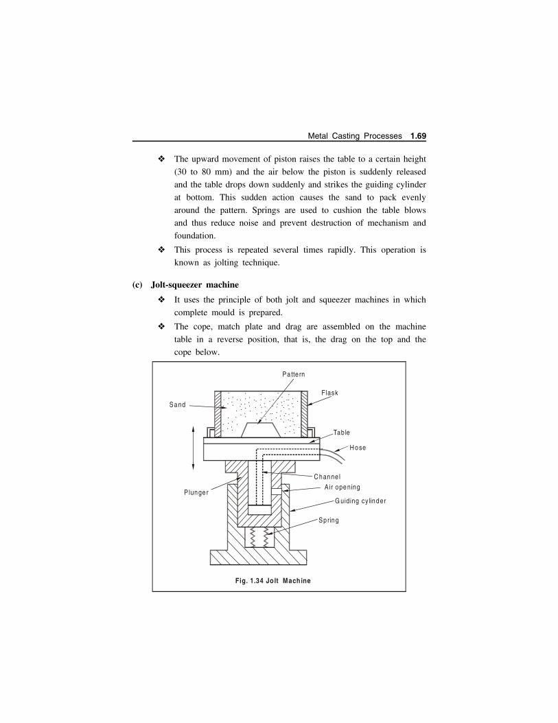
The upward movement of piston raises the table to a certain height
(30 to 80 mm) and the air below the piston is suddenly released
and the table drops down suddenly and strikes the guiding cylinder
at bottom. This sudden action causes the sand to pack evenly
around the pattern. Springs are used to cushion the table blows
and thus reduce noise and prevent destruction of mechanism and
foundation.
This process is repeated several times rapidly. This operation is
known as jolting technique.
(c) Jolt-squeezer machine
It uses the principle of both jolt and squeezer machines in which
complete mould is prepared.
The cope, match plate and drag are assembled on the machine
table in a reverse position, that is, the drag on the top and the
cope below.
......
..
.
......
..
.
......
..
.
......
..
.
......
..
..
...
..
..
.......
..
.
....
..
..
.
......
..
.
....
..
..
.
....
..
..
.
Tab le
Sand
P lunge r
H ose
C han ne l
A ir ope ning
Fig. 1.34 Jolt Machine
Patte rn
Flask
G uiding cy linder
Spring
Metal Casting Processes 1.69
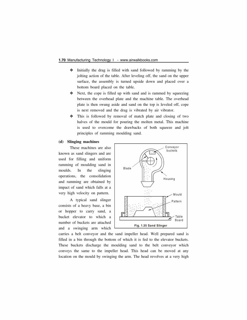
Initially the drag is filled with sand followed by ramming by the
jolting action of the table. After leveling off, the sand on the upper
surface, the assembly is turned upside down and placed over a
bottom board placed on the table.
Next, the cope is filled up with sand and is rammed by squeezing
between the overhead plate and the machine table. The overhead
plate is then swung aside and sand on the top is leveled off, cope
is next removed and the drag is vibrated by air vibrator.
This is followed by removal of match plate and closing of two
halves of the mould for pouring the molten metal. This machine
is used to overcome the drawbacks of both squeeze and jolt
principles of ramming moulding sand.
(d) Slinging machines
These machines are also
known as sand slingers and are
used for filling and uniform
ramming of moulding sand in
moulds. In the slinging
operations, the consolidation
and ramming are obtained by
impact of sand which falls at a
very high velocity on pattern.
A typical sand slinger
consists of a heavy base, a bin
or hopper to carry sand, a
bucket elevator to which a
number of buckets are attached
and a swinging arm which
carries a belt conveyor and the sand impeller head. Well prepared sand is
filled in a bin through the bottom of which it is fed to the elevator buckets.
These buckets discharge the moulding sand to the belt conveyor which
conveys the same to the impeller head. This head can be moved at any
location on the mould by swinging the arm. The head revolves at a very high
....
..
..
.....
..
..
..
...
..
..
...
..
....
..
..
..
...
..
..
.....
..
..
.
....
..
..
..
...
..
..
..
...
. .....
..
..
.
. . . ....
B lade
C onveyorbucke ts
H ousing
M ou ld
Pa tte rn
Tab leBoard
Fig. 1.35 Sand Slinger
.... .
....
..
.... . . ..
.. . .
1.70 Manufacturing Technology I - www.airwalkbooks.com

speed and, in doing so, throws a stream of moulding sand into the moulding
box at a high velocity. This process is known as slinging. The force of sand
ejection and striking into the moulding box compels the sand to get packed
in the box flask uniformly. By this way, the satisfactory ramming is
automatically get completed on the mould.
(e) Pattern draw machines
These machines enable easy withdrawal of patterns from the
moulds. They can be of the kind of stripping plate type and pin
lift or push off type.
Stripping plate type of pattern draw machines consists of a
stationary (platen or) table on which is mounted a stripping plate
which carries a hole in it.
The pattern is secured to a pattern plate and the latter to the
supporting ram.
The pattern is drawn through the stripping plate either by raising
the stripping plate or by keeping the stripping plate and mould
stationary by moving the ram downwards along with the pattern
plate.
1.11 MELTING FURNACES
The metal to be casted has to be in the molten or liquid state before
pouring into the mould. A furnace is used to melt the metal. A foundry
furnace only remelts the metal to be casted, it does not convert ore into useful
metal. A blast furnace performs basic melting (of iron ore) operation to get
pig iron. Different furnaces are used for melting and re-melting ferrous and
nonferrous materials.
1.11.1 Factors responsible for the selection of furnace
Considerations of initial, repair, maintenance and operation costs.
Availability and relative cost of various fuels in the particular
locality.
Melting efficiency, speed of melting.
Composition and melting temperature of the metal.
Metal Casting Processes 1.71

Degree of quality control required in respect of metal purification
of refining.
Cleanliness and noise level in operation.
Method used for pouring desired metal.
Chances of metal to absorb impurities during melting.
1.11.2 Types of Furnaces
Furnaces for melting different materials are given below
For Grey Cast Iron
Cupola furnace, Air furnace (or Reverberatory Furnace), Rotary furnace
and Electric arc furnace
For Steel
Electric furnaces, Open hearth furnace and Converter
For Non-ferrous Metals
(a) Reverberatory furnaces (fuel fired) (Al, Cu) - Stationary and Tilting
furnaces
(b) Rotary furnaces - Fuel fired & Electrically heated
(c) Induction furnaces (Cu, Al) - Low frequency & High frequency.
(d) Electric Arc furnaces (Cu)
(e) Crucible furnaces (Al, Cu) - Pit type, Tilting type, Non-tilting or
bale-out type & Electric resistance type (Cu)
(f) Pot furnaces (fuel fired) (Mg and Al) - Stationary and Tilting
1.11.3 Blast Furnace
Various kinds of mined iron ores are refined and converted to pig
iron in the blast furnace.
A typical blast furnace along with its various parts is shown in
Fig. 1.36.
It is large steel shell about 9 mt. in diameter which is lined with
heat resistant bricks.
It is set on the top of brick foundation. There are four major parts
of blast furnace from bottom to top hearth, bosh, stack and top.
1.72 Manufacturing Technology I - www.airwalkbooks.com
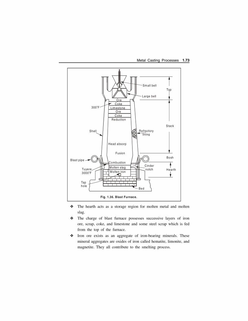
The hearth acts as a storage region for molten metal and molten
slag.
The charge of blast furnace possesses successive layers of iron
ore, scrap, coke, and limestone and some steel scrap which is fed
from the top of the furnace.
Iron ore exists as an aggregate of iron-bearing minerals. These
mineral aggregates are oxides of iron called hematite, limonite, and
magnetite. They all contribute to the smelting process.
Shell
Blast p ipe
Tuyere 3000 Fo
Tap hole
ReductionCoke
CokeOre
Ore300 Fo
Refractorylining
Stack
Large bell
Head absorp
Fusion
Combustion
M olten slagM olten iron
Cindernotch
Bosh
Hearth
Bed
Sm all bellTop
Fig. 1.36. Blast Furnace.
Lim estone
Metal Casting Processes 1.73

It takes about 1.6 tons of iron ore, 0.65 ton of coke, 0.2 ton of
lime-stone and about 0.05 ton of scrap iron and steel to produce
1 ton of pig iron.
For burning this charge, about 4 tons of air is required.The
impurities or other minerals are present in the ore may be silicon,
sulphur, phosphorus, manganese, calcium, titanium, aluminum, and
magnesium.
The output from the furnace in form of pig iron is collected in
large ladles from the tap hole existing at lower portion of furnace.
As the coke burns, aided by the air forced into the furnace, the
ore melts and collects in the hearth. As the melting process
proceeds, the entire mass settles and thus makes room for the
addition of charges at the top.
While the melting is going on, the limestone forms a slag with
the impurities.
Coke supplies the heat which reduces the ore and melts the iron.
The iron picks up carbon from the coke and impurities from the
ore. The carbon becomes part of the pig iron used in the making
of steel.
The pig iron is then processed for purification work for production
of various kinds of iron and steel in the form of ingots (large
sections) using different furnaces.
1.11.4 Cupola Furnace
Cupola furnace is employed for melting scrap metal or pig iron for
production of various cast irons. It is also used for production of nodular and
malleable cast iron. It is available in good varying sizes. The main
considerations in selection of cupola’s are melting capacity, diameter of shell
without lining or with lining, spark arrester. Cupolas are also used for melting
some copper alloys also.
1.74 Manufacturing Technology I - www.airwalkbooks.com
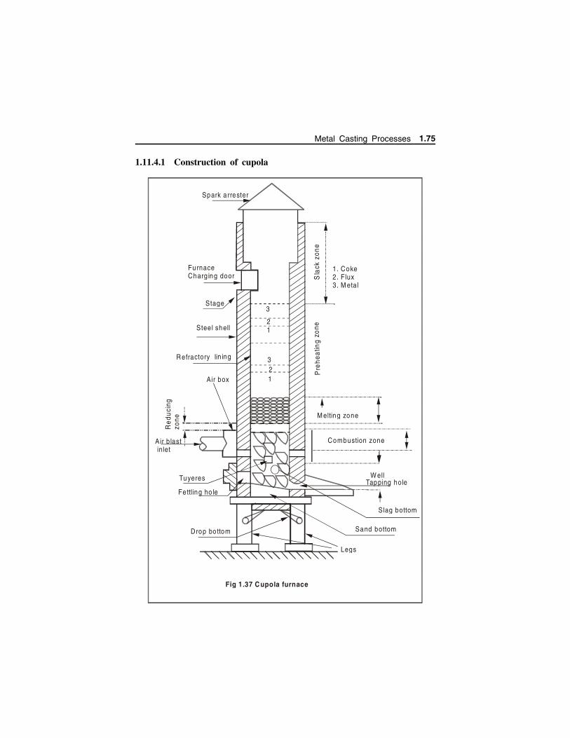
1.11.4.1 Construction of cupola
1. Coke2. Flux3. M etal
Spark a rrester
Furnace Charg ing door
Stage
Steel shell
Refractory lin ing
Air box
Red
uci
ng
zone
A ir b last inlet
Tuyeres
Fettling ho le
Drop bo ttom
Legs
Sand bottom
Slag bottom
W ellTapping hole
Combustion zone
M elting zone
Pre
heat
ing
zone
Sla
ck z
one
1
3
1
3
2
2
Fig 1.37 C upola furnace
Metal Casting Processes 1.75
A cupola is a cylindrical shell either welded or riveted from a
boiler plate of 6-10 mm thick and is open both at its top and
bottom, lined with firebrick and clay supported on cast iron legs.
Fig 1.37
It has cast iron door at the bottom to open or close and used to drop
the left out contents of cupola.
Air from blower comes through the blast pipe and enters wind
box which surround the cupola and supplies air uniformly to
tuyeres.
Tuyeres extend through the steel shell and refractory wall to the
combustion zone and supply air necessary for combustion.
There is a tap hole at the bottom from where molten metal is
taken out to pour in mould. The fire in cupola is also lit through
the tap hole.
Slag hole is present opposite and above the tap hole. It is 250
mm below tuyeres. Slag is removed from slag hole.
Cupola is provided with charging platform and charging door at
suitable height to feed the charge.
Capacity of cupola varies from 1 to 15 tons. They are 6 m in
height and diameters vary from 750mm to 2.5mts.
Sometimes they are fitted with collector, filter and precipitator to
minimize pollution.
1.11.4.2 Various Zones of Cupola Furnace
Various chemical reactions taking place in different zones of cupola
are:
(a) Well
The space between the bottom of the tuyeres and the sand bed inside
the cylindrical shell of the cupola is called as well of the cupola. As the
melting occurs, the molten metal is collected in this portion before tapping
out.
1.76 Manufacturing Technology I - www.airwalkbooks.com

(b) Combustion zone
The combustion zone of Cupola is also called as oxidizing zone.
Combustion of coke takes place in this zone. It is located between the upper
of the tuyeres and a theoretical level above it. The total height of this zone
is normally from 150 mm to 300 mm. The combustion actually takes place
in this zone by consuming the free oxygen completely from the air blast and
generating tremendous heat. The heat generated in this zone is sufficient
enough to meet the requirements of other zones of cupola. The heat is also
further evolved due to oxidation of silicon and manganese. A temperature of
about 1540C to 1870C is achieved in this zone. A few of the exothermic
reactions that take place in this zone are represented as :
C O2 CO2 Heat
Si O2 SiO2 Heat
2Mn O2 2MnO Heat
(c) Reducing zone
Reducing zone of Cupola is also known as the protective zone which
is located between the upper level of the combustion zone and the upper
level of the coke bed. In this zone, CO2 is changed to CO through an
endothermic reaction, as a result of which the temperature falls from
combustion zone temperature to about 1200C at the top of this zone. The
important chemical reaction that takes place in this zone is given below.
CO2 C coke 2CO Heat
Nitrogen does not participate in the chemical reaction occurring in this
zone as it is also the other main constituent of the upward moving hot gases.
Because of the reducing atmosphere in this zone, the charge is protected
against oxidation.
(d) Melting zone
The lower layer of metal charge above the lower layer of coke bed is
termed as melting zone of Cupola. The metal charge starts melting in this
zone and trickles down through coke bed and gets collected in the well.
Metal Casting Processes 1.77

Sufficient carbon content picked by the molten metal in this zone is
represented by the chemical reaction given below.
3Fe 2CO Fe3C CO2
(e) Preheating zone
Preheating zone starts from the upper end of the melting zone and
continues up to the bottom level of the charging door. This zone contains a
number of alternate layers of coke bed, flux and metal charge. The main
objective of this zone is to preheat the charges from room temperature to
about 1090C before entering the metal charge to the melting zone. The
preheating takes place in this zone due to the upward movement of hot gases.
During the preheating process, the metal charge in solid form picks up some
sulphur content in this zone.
(f) Stack
The empty portion of cupola above the preheating zone is called as
stack. It provides the passage to hot gases to go to atmosphere from the
cupola furnace.
1.11.4.3 Operation / Working of Cupola
The various steps in operating cupola are:
Preparation of cupola
Lightening of cupola
Charging of cupola
Melting
Slagging and metal tapping
Dropping down
Preparation Bottom doors are opened and the contents (unburned coke, slag,
metal) of previous melting are dumped under furnace and removed.
Slag, coke, iron sticking to the side walls of the furnace are
chipped off.
Damaged bricks are replaced and damaged refractory lining is
patched up and then bottom doors are closed.
1.78 Manufacturing Technology I - www.airwalkbooks.com
Lightening Cupola is fired 3-4 hrs before molten metal is needed.
Soft, dry wood are placed on the sand bed rammed above the
bottom door. Coke is placed above the wooden pieces till the
tuyeres. Wood is ignited through tap hole.
Charging of Cupola
After the coke bed is properly ignited, the cupola is charged from
the charging door.Charging of cupola involves adding of alternate
layers of limestone (flux), metal (iron) and fuel (coke) up to the
level of charging door.
Flux is a substance aiding in formation of slag for removing
impurities. Commonly used flux are limestone, others are sodium
carbonate, fluorospar (CaF2), calcium carbide and dolomite.
Metal charge may consist of pig iron, cast iron scrap and steel
scrap.
Melting
After charging, a soak period of 30-60 minutes is given to charge
for preheating.
At the end of soaking period the blast is turned on. The coke
becomes fairly hot to melt the metal charge.
Now molten metal starts accumulating in the hearth and appears
at tap hole.
Tap hole is closed with a plug and metal is allowed to collect
after five minutes.
Slagging and metal tapping
After enough slag is accumulated the slag hole is opened and the
slag is collected in a container and disposed off.
The plug is knocked off from the tap hole and the molten metal
is tapped pouring into the mould.
Metal Casting Processes 1.79
Dropping down
As cupola heat charging is stopped, all the content of cupola is
allowed to melt till one or two charge is left above coke bed.
Now the air blast is switch off and the prop under bottom door
is knocked down and the remains in cupola are dropped down on
the floor or collected in bucket.
The dropped cupola remains are quenched with water and then
metal, coke remains are recovered for next use.
1.11.4.4 Applications of Cupola
Cupola is most widely used for melting practices for production
of grey cast iron, nodular cast iron, malleable cast iron and alloy
cast iron.
It can be used for melting some copper-base alloys.
It can be used in duplexing and triplexing operations for making
of steel, malleable cast iron and ductile cast iron.
1.11.4.5 Thermal Efficiency of Cupola Furnace
Thermal efficiency of cupola furnace is the ratio of heat actually
utilized in melting and superheating the metal to the heat evolved in it through
various means. The total heat evolved involves the heat due to burning of
coke, heat evolved due to oxidation of iron, Si and Mn and heat supplied by
the air blast.
During melting it is observed that approximately 48- 70 % of the
evolved heat is going as waste.
% Thermal efficiency
Heat utilized in Preheating, melting and superheatingHeat evolved in the furnace
100
1.11.4.6 Advantages of Cupola
Cupola is simple and easier in construction and easy to operate.
Low initial cost, low operation and maintenance costs compared to
other furnaces of same capacity.
1.80 Manufacturing Technology I - www.airwalkbooks.com
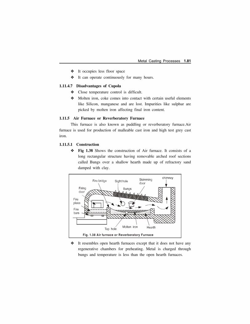
It occupies less floor space
It can operate continuously for many hours.
1.11.4.7 Disadvantages of Cupola
Close temperature control is difficult.
Molten iron, coke comes into contact with certain useful elements
like Silicon, manganese and are lost. Impurities like sulphur are
picked by molten iron affecting final iron content.
1.11.5 Air Furnace or Reverberatory Furnace
This furnace is also known as puddling or reverberatory furnace.Air
furnace is used for production of malleable cast iron and high test grey cast
iron.
1.11.5.1 Construction
Fig 1.38 Shows the construction of Air furnace. It consists of a
long rectangular structure having removable arched roof sections
called Bungs over a shallow hearth made up of refractory sand
damped with clay.
It resembles open hearth furnaces except that it does not have any
regenerative chambers for preheating. Metal is charged through
bungs and temperature is less than the open hearth furnaces.
Fig. 1.38 Air furnace or Reverberatory Furnace
Metal Casting Processes 1.81

1.11.5.2 Working
The air furnace is charged (i.e. metal, scrap etc.,) through bungs.
Oil or pulverized bituminous coal is placed on the fire place.
The air and fuel are blown through one end of furnace so that the
flame passes over the metal charge.
The flame and hot gases heat up the air furnace roof and walls.
The heat reflected and radiated from the roof /walls is utilized to
super heat the metal charge.
Acid slag protects the molten metal from direct exposure of flame.
The molten metal is tapped from the tap hole.
1.11.5.3 Difference between air furnace and cupola furnace
S. No Air Furnace Cupola furnace
1 Time is available to analyze thesamples of molten metal andhence control of chemicalcomposition is possible.
Time is not available due tocontinuous tapping and hencecontrol in chemical compositionis not possible.
2 Only flame not fuel comes incontact with metal and henceelements like sulphur, carbon iseliminated from molten metal
Flame & fuel come in contactwith molten metal and henceelements like sulphur, carbon isadded in molten metal.
3 Melting ratio (metal to fuel) is2:1,so high working costs.
Melting ratio (metal to fuel) is10:1, so low working costs.
4 Air furnace supplies moltenmetal in large quantities inbatches therefore facilitates largecastings.
Cupola supplies small butcontinuous supply of cast iron,so it can be used for largenumber of small castings.
5 Initial costs are high. Initial costs are Low.
6 Capacity varies from 5 to 50tons.
Capacity varies from 1 to 15tons.
1.11.5.4 Advantages of Air furnaces Time is available to analyze the samples of molten metal and hence
control of chemical composition is possible.
1.82 Manufacturing Technology I - www.airwalkbooks.com

Only flame not fuel comes in contact with metal and hence
elements like sulphur, carbon is eliminated from molten metal.
Air furnace supplies molten metal in large quantities in batches
therefore facilitates large castings.
Capacity varies from 5 to 50 tons.
1.11.5.5 Disadvantages of Air furnaces Melting ratio (metal to fuel) is 2:1, so high working costs.
Initial costs are high.
1.11.6 Rotary Melting FurnaceAir furnace used for making malleable cast iron is difficult to operate
and lot of fuel is wasted, a rotary furnace is an improvement over the same.
1.11.6.1 ConstructionA rotary furnace consists of a horizontal cylindrical steel shell lined
with refractory material and mounted on rollers (Fig. 1.39) for rotating or
rocking purposes. The cylindrical shell revolves completely at about 1 RPM.
Burner at one end burns the fuel and resulting high temperature flame
melts and reheats the metal charge lying in the shell. There is a tapping spout
to tap the molten metal. The exhaust gas is sent to the preheater to trap the
flue gas energy to the incoming cold air.
R efractory lining
Fuel & a ir
Bu rne r
Arrangem ent o f ro ta tion
Tappingspout
M oltenm etal
Exhaust box
To p re heater
S tee l shell
Fig. 1.39. Rotary Furnace
Metal Casting Processes 1.83

1.11.6.2 Working Rotary furnace is charged from one of the conical ends by
removing burner or exhaust box temporarily.
The melting (metal-to-fuel) ratio is 5 : 1 for pulverized coal and
6 : 1 for oil fuel.
Due to rotation of the furnace the metal get heated from the walls
and is melted more efficiently and faster.
The burner at one end burns the fuel and the resulting high
temperature flame melts and superheats the metal charge lying in
the shell.
Since molten metal does not come in contact with the fuel (such
as coal), there is no danger of carbon or sulphur pick up.
The slag floating on the molten iron protects the metal and its
constituent elements (like Si, Mn etc.) from oxidation.
After the melting is complete, plugged tap hole is opened and the
furnace is rotated slowly until the tap hole reaches the level of
molten metal in the furnace, then the same (i.e. metal) can be
poured into a ladle.
In case the tap hole is not provided in the cylindrical body, the
liquid metal can be tapped from the other end of the furnace.
Besides tapping, this end is used for charging, slagging and
evacuating the products of combustion.
1.11.6.3 Advantages A sample of molten metal can be drawn before pouring and
analyzed as regards its chemical composition which subsequently
can be accurately controlled by additions if required.
Charge in a rotary furnace can be super-heated to high
temperatures.
Cheap and light scrap like steel clippings or cast iron borings
which cannot be used in cupola, may be added in the charge
without affecting the melt quality.
1.84 Manufacturing Technology I - www.airwalkbooks.com
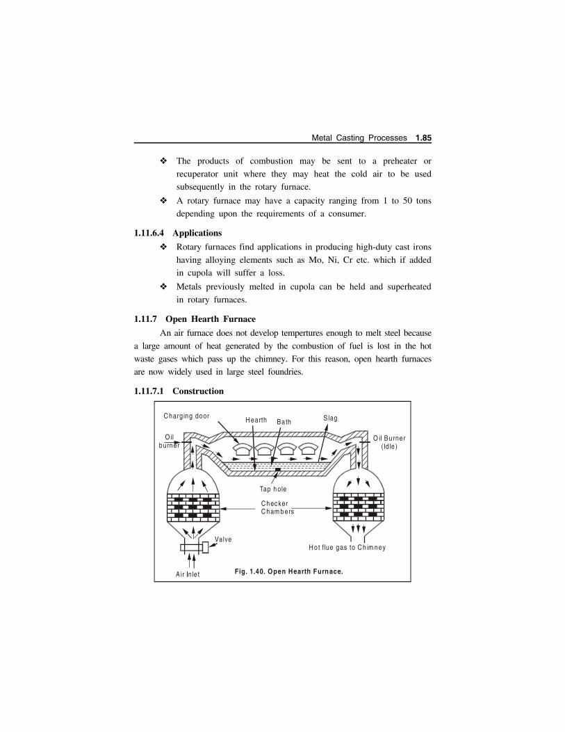
The products of combustion may be sent to a preheater or
recuperator unit where they may heat the cold air to be used
subsequently in the rotary furnace.
A rotary furnace may have a capacity ranging from 1 to 50 tons
depending upon the requirements of a consumer.
1.11.6.4 Applications
Rotary furnaces find applications in producing high-duty cast irons
having alloying elements such as Mo, Ni, Cr etc. which if added
in cupola will suffer a loss.
Metals previously melted in cupola can be held and superheated
in rotary furnaces.
1.11.7 Open Hearth Furnace
An air furnace does not develop tempertures enough to melt steel because
a large amount of heat generated by the combustion of fuel is lost in the hot
waste gases which pass up the chimney. For this reason, open hearth furnaces
are now widely used in large steel foundries.
1.11.7.1 Construction
C hecker C ham bers
Tap h ole
O il Bu rne r(Id le )
Valve
C harg ing door H earth Ba th S lag
H ot flue gas to C h im ney
O il burner
Fig. 1.40. Open Hearth Furnace.Air nle t�
Metal Casting Processes 1.85
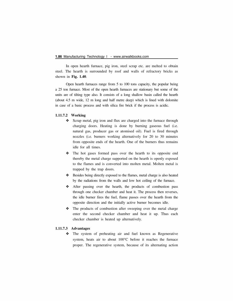
In open hearth furnace, pig iron, steel scrap etc. are melted to obtain
steel. The hearth is surrounded by roof and walls of refractory bricks as
shown in Fig. 1.40.
Open hearth furnaces range from 5 to 100 tons capacity, the popular being
a 25 ton furnace. Most of the open hearth furnaces are stationary but some of the
units are of tilting type also. It consists of a long shallow basin called the hearth
(about 4.5 m wide, 12 m long and half metre deep) which is lined with dolomite
in case of a basic process and with silica fire brick if the process is acidic.
1.11.7.2 Working Scrap metal, pig iron and flux are charged into the furnace through
charging doors. Heating is done by burning gaseous fuel (i.e.
natural gas, producer gas or atomised oil). Fuel is fired through
nozzles (i.e. burners working alternatively for 20 to 30 minutes
from opposite ends of the hearth. One of the burners thus remains
idle for all times.
The hot gases formed pass over the hearth to its opposite end
thereby the metal charge supported on the hearth is openly exposed
to the flames and is converted into molten metal. Molten metal is
trapped by the trap doors.
Besides being directly exposed to the flames, metal charge is also heated
by the radiations from the walls and low hot ceiling of the furnace.
After passing over the hearth, the products of combustion pass
through one checker chamber and heat it. The process then reverses,
the idle burner fires the fuel, flame passes over the hearth from the
opposite direction and the initially active burner becomes idle.
The products of combustion after sweeping over the metal charge
enter the second checker chamber and heat it up. Thus each
checker chamber is heated up alternatively.
1.11.7.3 Advantages The system of preheating air and fuel known as Regenerative
system, heats air to about 100C before it reaches the furnace
proper. The regenerative system, because of its alternating action
1.86 Manufacturing Technology I - www.airwalkbooks.com

speeds up the melting of metal and develops temperatures enough
to melt steel.
It has high thermal efficiency.
Before tapping the molten metal into the ladle, a sample of the
same may be tested as regards its chemical composition.
1.11.7.4 ApplicationsOpen hearth furnace is used for melting steels,
It may also be used for melting Al, Cu and their alloys in large
quantities.
1.11.8 Convertor
Converters are steel-making units. A Converter actually converts pig
or cast iron into steel by blowing air through (bessemer) or over (side blown)
molten iron. Converters are of two types:
...
...
.... .
...
.
...
.... .
...
.
...
.... .
...
.
...
.... .
...
.
...
....
.
.
.
...
..
...
.. .
.
...
.
...
...
. ..
..
.
...
.
...
...
. ..
..
.
...
.
.
...
...
. ..
..
.
.
.. .
...
. ..
..
.. . ..
. . .. . ..
. . . .
..
..
...
..
.
..
..
. ..
..
... ..
..
..
. ..
..
.. . ....
.. . ....
.. ..
..
..
..
.
A ir Blast
W ind box
Tuyeres
M olten m eta l
Shell
Trunnion forTilting
Refractory lining
Flue gas
Fig. 1.41 Side-blown converter
Metal Casting Processes 1.87

Bessemer or bottom blower Converters in which a blast of cold
air is blown from the bottom and,
Tropellas or side-blown converter in which the blast of cold air
is blown from the side of the converter.
A side blown converter can produce high temperature molten steels
(3200 3300F) which are required to pour thin sectioned steel
castings.
1.11.8.1 Working
The metal charge is melted in a cupola and it is brought to the
converter for refining the same.
The converter is tilted down, the molten cupola iron is given a
desulfurizing treatment in the ladle and is transferred to the
converter which is then tilted back to the upright position.
Cold air is blown through tuyeres located in the side of the
converter over the molten iron at a pressure of about about 0.35
bar.
The oxygen of the cold air burns (oxidizes) Mn and Si to form
slag; the carbon is oxidized out of the charge (melt) and produces
CO and CO2.
These oxidizing reactions are exothermic and thus no fuel is
required for heating purposes; rather the heat generated by these
reactions raises the temperature of the metal to about 1700Cwhich is sufficient for pouring purposes.
The cold air blow is continued (only) until carbon is reduced to
about 0.1 to 0.2%.
The colour and length of the flame originating from the converter
nose gives an indication of the rate of oxidation and the order of
oxidation of the elements (like C, Si and Mn).
Photoelectric devices can be used to mark the end of the air blast.
1.88 Manufacturing Technology I - www.airwalkbooks.com
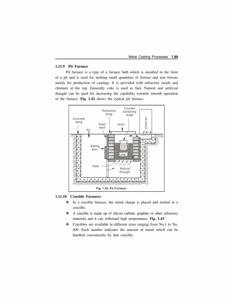
1.11.9 Pit Furnace
Pit furnace is a type of a furnace bath which is installed in the form
of a pit and is used for melting small quantities of ferrous and non ferrous
metals for production of castings. It is provided with refractory inside and
chimney at the top. Generally coke is used as fuel. Natural and artificial
draught can be used for increasing the capability towards smooth operation
of the furnace. Fig. 1.42 shows the typical pit furnace.
1.11.10 Crucible Furnaces
In a crucible furnace, the metal charge is placed and melted in a
crucible.
A crucible is made up of silicon carbide, graphite or other refractory
materials and it can withstand high temperatures. Fig. 1.43
Crucibles are available in different sizes ranging from No.1 to No.
400. Each number indicates the amount of metal which can be
handled conveniently by that crucible.
coke
R efracto rylining
C ruciblecon ta in ing
m etal
cover
Chi
mn
ey
S tee l she ll
P it
C oncretelining
S lid ingdoor
G ateN a turalD raught
Fig. 1.42. Pit Furnace.
Metal Casting Processes 1.89

A crucible furnace is though mainly used for melting of nonferrous
metals and low melting point alloys, it is being used for melting
cast iron and steel also.
R efractory lin ing
.. . .
....
. ....
.. .
... .. .
....
. ....
.. .
... ..
.
..
.
Fig. 1.43 (b) Stationery Pot
C ove r
Fuel
S tee l she ll
R e fractory lin ing
L ift-ou tcruc ib le
.. . .
....
. ....
.. .
....
. ....
.. .
....
. ....
Fuel
Supp ort b lo ck
Fig. 1.43 (a) Lift ou t cruc ible
C ove r
1.90 Manufacturing Technology I - www.airwalkbooks.com
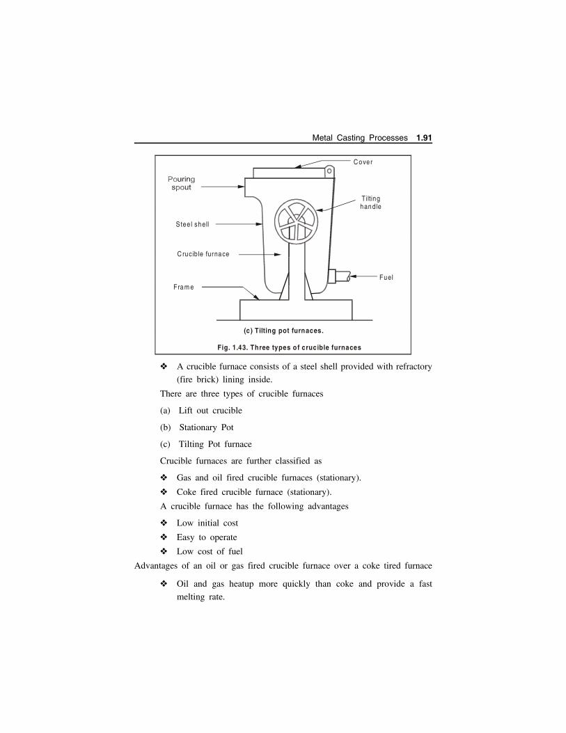
A crucible furnace consists of a steel shell provided with refractory
(fire brick) lining inside.
There are three types of crucible furnaces
(a) Lift out crucible
(b) Stationary Pot
(c) Tilting Pot furnace
Crucible furnaces are further classified as
Gas and oil fired crucible furnaces (stationary).
Coke fired crucible furnace (stationary).
A crucible furnace has the following advantages
Low initial cost
Easy to operate
Low cost of fuel
Advantages of an oil or gas fired crucible furnace over a coke tired furnace
Oil and gas heatup more quickly than coke and provide a fast
melting rate.
(c ) Tilting pot furnaces.
Fra m e
C over
Tiltinghandle
Fuel
S tee l shell
C rucible furnace
Fig. 1.43. Three types of crucible furnaces
Metal Casting Processes 1.91

The furnace heating can be immediately stopped in oil fired
furnace
A coke fired furnace needs an enclosed ash pan whereas nothing
like that is required in oil or gas fired furnaces.
Floor space can be saved by using oil or gas fired furnace. It
requires less floor space, less labour with improved and easier
control of temperature.
1.11.11 Electric Furnaces
Electric furnaces are employed for the production of high quality
castings, because: the furnace atmosphere can be more closely controlled,
losses by oxidation can be eliminated, alloying elements can be added without
fear of (their) loss (due to oxidation). composition of the melt and its
temperature can be accurately controlled.
Electric furnaces are used for melting steels (including alloy steel i.e.,
tool steels and stainless steels), high-test and alloy cast iron, brasses. Capacity
of electric furnaces ranges from 250 kg to 10 tons.
1.11.11.1 Types of Electric Furnaces
Direct arc furnace.
Indirect arc furnace.
Resistance heating type.
Coreless type (or High frequency) induction furnace.
Core type (or Low frequency) induction furnace.
1.11.11.2 Direct Arc furnace
Direct arc furnace has its diameter up to 6 metres and capacity of
about 125 tons.
It re-melts steels of widely differing compositions.
Rating of the transformers supplying power to the arc ranges from
800 KVA to 40,000 KVA.
A 50 ton direct arc furnace may require arc current of the order
of 25000 Amps and arc voltage of about 250V.
1.92 Manufacturing Technology I - www.airwalkbooks.com
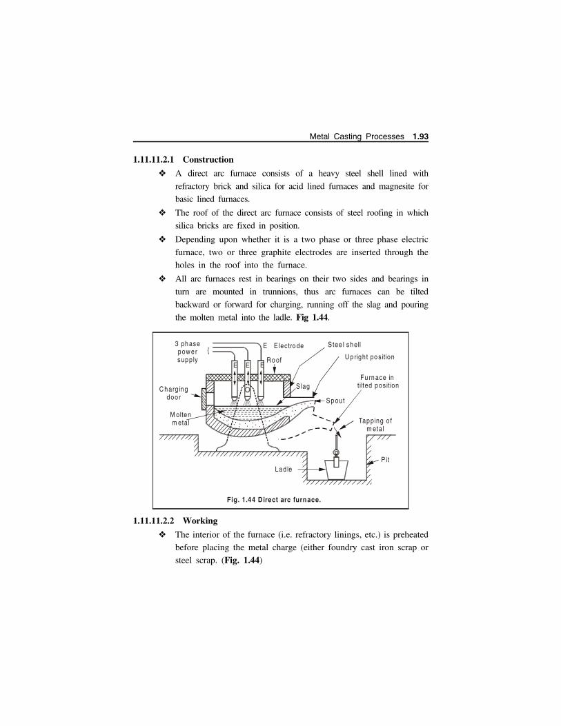
1.11.11.2.1 Construction
A direct arc furnace consists of a heavy steel shell lined with
refractory brick and silica for acid lined furnaces and magnesite for
basic lined furnaces.
The roof of the direct arc furnace consists of steel roofing in which
silica bricks are fixed in position.
Depending upon whether it is a two phase or three phase electric
furnace, two or three graphite electrodes are inserted through the
holes in the roof into the furnace.
All arc furnaces rest in bearings on their two sides and bearings in
turn are mounted in trunnions, thus arc furnaces can be tilted
backward or forward for charging, running off the slag and pouring
the molten metal into the ladle. Fig 1.44.
1.11.11.2.2 Working
The interior of the furnace (i.e. refractory linings, etc.) is preheated
before placing the metal charge (either foundry cast iron scrap or
steel scrap. (Fig. 1.44)
EE E
E E lectro de
R o of
S tee l shell
S lag
U p right po s ition
Sp ou t
Fu rn ace in tilted pos ition
Tapping o f m etal
3 ph ase pow ersupply
C h arg ing door
M oltenm etal
P itLad le
... . .. ... .. .. ..... .
..
.... . . ..
.. ..
.... ...
..
Fig. 1.44 Direct arc furnace.
Metal Casting Processes 1.93

Preheating is done by alternatively striking and breaking the arc
between the (vertical) electrodes and used electrode pieces
(removed after pre heating) kept on the hearth.
Once the cold charge has been placed on the hearth of the furnace,
electric arc is drawn between the electrodes and the surface of the
metal charge by lowering the electrodes down till the current jumps
the gap between the electrode and the charge surface.
The arc gap between the electrode and the charge is regulated by
automatic controls
Three arcs burning simultaneously produce a temperature of the
order of 11000F, and readily melt flux, sand and the metal scrap.
The slag formed due to melting of flux, sand etc. covers the molten
pool of metal. Slag present on the top of the molten metal bath
reduces its oxidation, refines the metal, and protects roof and side
walls from the large amount of heat radiated from the molten metal.
Before pouring the liquid metal into the ladle, the furnace is tilted
backward and the slag is poured off from the charging door.
The furnace is then tilted forward and the molten metal is emptied
into ladles.
1.11.11.2.3 Advantages of Direct Arc Furnace
Direct arc furnaces undertake a definite metal refining sequence.
Molten metal is refined to a proper analysis and is heated to a
suitable pouring temperature.
Analysis of melt can be kept to accurate limits.
High thermal efficiency as high as about 70%
It is easy to control the furnace atmosphere above the molten
metal.
Alloying elements like Cr, Ni and W can be recovered from the
scrap with little losses.
It can make steel directly from pig iron and steel scrap.
Arc furnace is larger and its electrical equipment is cheaper to
install.
1.94 Manufacturing Technology I - www.airwalkbooks.com

An arc furnace is preferred for its quicker readiness for use.
1.11.11.2.4 Limitations
Heating costs are higher than for other furnaces.
This however can be adjusted to some extent by using low cost
scrap turnings or borings as metal charge.
1.11.11.2.5 Applications
In general, high quality carbon steels and alloy steels in bulk are made
in electric direct arc furnace.
Cast iron from foundry cast iron scrap.
1.11.11.3 Indirect Electric Arc Furnace
An indirect electric arc furnace has a capacity ranging from a few
Kgs to 2 Tons and is used for smaller melts.
An electric arc is struck between two graphite electrodes and the
metal charge does not form a part of the electric circuit.
The metal comes in contact with hot refractory lining and picks
up heat for melting from the linings and also metal charge melts
because of the radiations from the arc and the hot refractory walls
of the furnace and conduction from the hot refractory (wall)
linings, when the furnace rocks and molten metal rolls over the
same.
1.11.11.3.1 Construction
An indirect arc furnace consists of a barrel type shell made up of steel
plates, having refractory lining inside.
There are two openings for the two graphite electrodes and the third
is for the charging door for feeding the metal charge into the furnace built
up with pouring spout.
Furnace is mounted on the rollers (Refer Fig. 1.45) which are driven
by a rocking drive unit to rock the furnace back and forth during melting.
While the furnace rocks, liquid metal washes over the heated refractory linings
and absorbs heat from them. In addition during rocking, metal charge
constituents get mixed up thoroughly.
Metal Casting Processes 1.95

Rocking of furnace speeds up melting, stirs the molten metal, avoids
refractory linings from getting over-heated and thus increases their life.
The angle of rocking of furnace is adjusted in such a manner that the
liquid metal level remains below the pouring spout.
1.11.11.3.2 Operation
The furnace is charged with pig iron and scrap is placed above.
When the electric power is on, graphite electrodes are brought
nearer till the current jumps and an electric arc is set up between
them. The heat generated in the arc is responsible for melting the
charge.
A number of alloys one after the other can be easily melted in
this type of furnace. Additions of elements like Ni, Co, Cr, W,
Mo, V etc. can be made easily and conveniently.
Chargingdoor
Electrode 1
Power Lead
Pouring Spout
Support
Ro lle rs
M olten m etal
Electrode 2
Refractory lining
ShellArc
Fig. 1.45. Indirect Electric Arc Furnace.
1.96 Manufacturing Technology I - www.airwalkbooks.com

1.11.11.3.3 Limitations
The initial cost of the furnace and its auxiliary equipment is high.
It is limited to melting high quality metals and in smaller
quantities.
Time available for analysing the melt composition is very small,
thus the melt charge should be carefully selected and it should be
of required chemical composition.
1.11.11.3.4 Applications
High frequency induction furnace is very useful for special alloy
and high quality steels in small quantities.
It is used for melting Cast iron, Steel, Copper and its alloys.
1.11.11.4 Core Type (Or Low Frequency) / Induction Furnace
Construction and working A core type induction furnace operates as an ordinary transformer.
The primary coil has many turns and is wound on a laminated steel
core whereas the secondary coil of the transformer has one turn which
is a channel or loop of liquid metal within the furnace.
The furnace uses a. c. supply of 50 cycles per second.
Secondary currents (having high current values at low voltage) are
induced in the metal bath around the core and the heat is generated
due to the electrical resistance of the metal (charge) to the flow
of secondary currents.
Channel of molten metal around the coil connects to the main
metal container above, which holds the metal charge.
The metal in the channel gets heated, circulates through and stirs
the metal in the container and thus the melting process (of the
metal charge) proceeds.
Once the melt reaches the required pouring temperature it can be
ladled out from the pouring spout (refer Fig. 1.46).
Metal Casting Processes 1.97
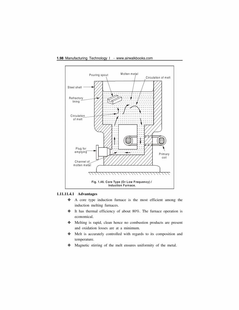
1.11.11.4.1 Advantages
A core type induction furnace is the most efficient among the
induction melting furnaces.
It has thermal efficiency of about 80%. The furnace operation is
economical.
Melting is rapid, clean hence no combustion products are present
and oxidation losses are at a minimum.
Melt is accurately controlled with regards to its composition and
temperature.
Magnetic stirring of the melt ensures uniformity of the metal.
Pouring spou t
S tee l shell
R e fractorylin ing
C ircu la tio no f m elt
P lug fo rem pty ing
C hanne l ofm olten m eta l
C ircu la tio n of m elt
P rim ary co il
M olten m eta l
Fig. 1.46. Core Type (Or Low Frequency) / Induction Furnace.
1.98 Manufacturing Technology I - www.airwalkbooks.com

1.11.11.4.2 Limitations
This Furnace cannot be operated on solid metal charge
Furnace operation can be started only after filling the channels
with molten metal procured from some other furnace.
If once by chance metal gets solidified in the channels it cannot
remelted by the heat created in the secondary coil.
Core type furnace is more or less restricted to melt one alloy. For
melting another alloy, the furnace should be emptied, thoroughly
cleaned and restarted with the new molten alloy.
A core type furnace is not suitable for intermittent operation.
1.11.11.4.3 Applications
A core type furnace is used primarily for remelting non-ferrous
metals and their alloys.
It can be used for producing malleable cast iron also.
1.11.12 Overall Comparison Of Melting Furnaces
S. NoFurnace
typeHeating Method Applications
1 Crucible
Pit type Solid fuel, oil or gas Most of alloys exceptsteel
Tilting type Solid fuel, oil or gas Most of alloys exceptsteel
Bale out Gas, oil Light casting (diecastings)
2 Cupola Coke Cast iron, steel (duplexconverter)
3 Rever-beratory(air)
Solid fuel. gas or oil Non-ferrous alloys, castiron, malleable iron.
4 Rotary Pulverized solid fuel, gasor oil
Non-ferrous alloys, castiron, malleable andspecial. Duplex holding.
5 Open hearth Oil,Gas Steel
Metal Casting Processes 1.99

S. NoFurnace
typeHeating Method Applications
6 Arc furnace:
Direct arc Arc on metal charge Steel, Cast Iron
Indirect arc Radiant arc Non-ferrous alloys, highalloy steel and specialirons.
7 Inductionfurnace:
Core type Low frequency induction Cast Iron, non-ferrousalloys.
Coreless High frequency induction Steel and alloy steel.
8 Resistancefurnace
Resistor Radiant resistor rod Steel, cast iron, copperalloys.
Resistance Elements (shroud orimmersion)
Non-ferrous alloys.
1.12 GATING SYSTEMThe assembly of channels which facilitates the molten metal to enter
in to the mould cavity is called the gating (or) gating system.
Pouring Basin
Sprue
Sprue W e ll
G ateR unner In G a tes
C asting
In G a tes
Fig. 1.47 Gating System
1.100 Manufacturing Technology I - www.airwalkbooks.com
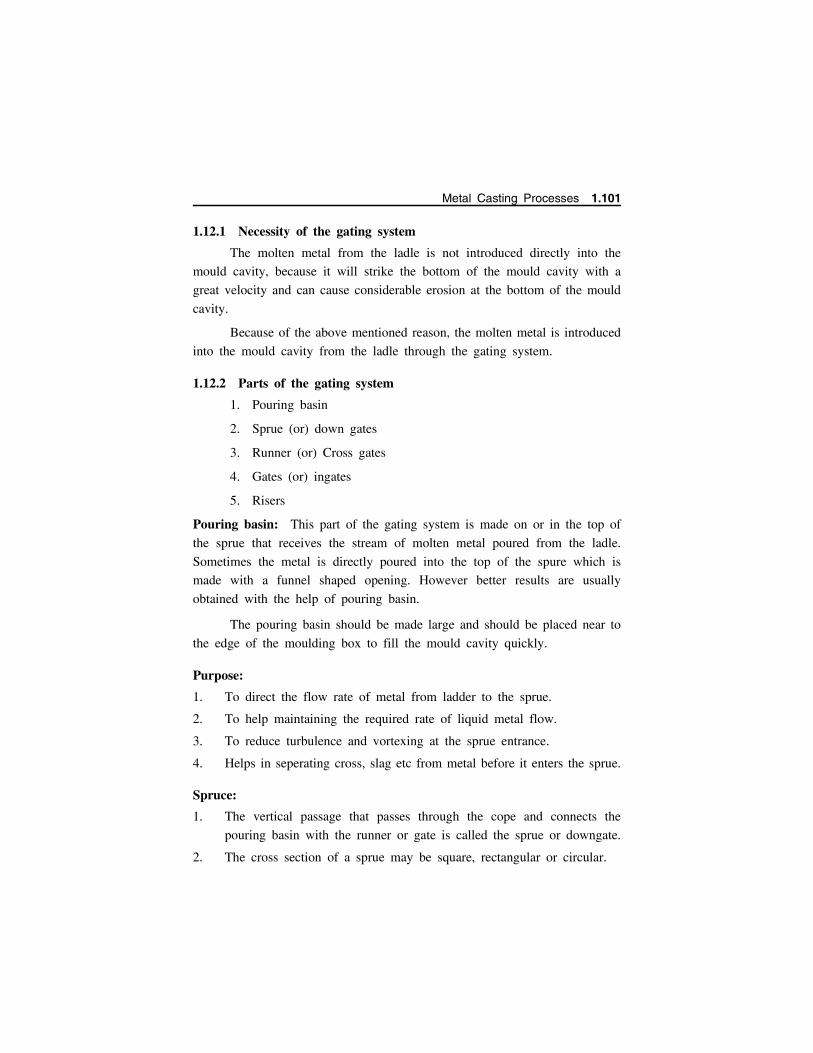
1.12.1 Necessity of the gating system
The molten metal from the ladle is not introduced directly into the
mould cavity, because it will strike the bottom of the mould cavity with a
great velocity and can cause considerable erosion at the bottom of the mould
cavity.
Because of the above mentioned reason, the molten metal is introduced
into the mould cavity from the ladle through the gating system.
1.12.2 Parts of the gating system
1. Pouring basin
2. Sprue (or) down gates
3. Runner (or) Cross gates
4. Gates (or) ingates
5. Risers
Pouring basin: This part of the gating system is made on or in the top of
the sprue that receives the stream of molten metal poured from the ladle.
Sometimes the metal is directly poured into the top of the spure which is
made with a funnel shaped opening. However better results are usually
obtained with the help of pouring basin.
The pouring basin should be made large and should be placed near to
the edge of the moulding box to fill the mould cavity quickly.
Purpose:
1. To direct the flow rate of metal from ladder to the sprue.
2. To help maintaining the required rate of liquid metal flow.
3. To reduce turbulence and vortexing at the sprue entrance.
4. Helps in seperating cross, slag etc from metal before it enters the sprue.
Spruce:
1. The vertical passage that passes through the cope and connects the
pouring basin with the runner or gate is called the sprue or downgate.
2. The cross section of a sprue may be square, rectangular or circular.
Metal Casting Processes 1.101
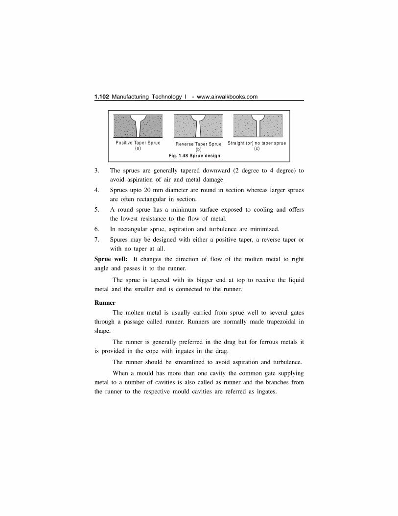
3. The sprues are generally tapered downward (2 degree to 4 degree) to
avoid aspiration of air and metal damage.
4. Sprues upto 20 mm diameter are round in section whereas larger sprues
are often rectangular in section.
5. A round sprue has a minimum surface exposed to cooling and offers
the lowest resistance to the flow of metal.
6. In rectangular sprue, aspiration and turbulence are minimized.
7. Spures may be designed with either a positive taper, a reverse taper or
with no taper at all.
Sprue well: It changes the direction of flow of the molten metal to right
angle and passes it to the runner.
The sprue is tapered with its bigger end at top to receive the liquid
metal and the smaller end is connected to the runner.
Runner
The molten metal is usually carried from sprue well to several gates
through a passage called runner. Runners are normally made trapezoidal in
shape.
The runner is generally preferred in the drag but for ferrous metals it
is provided in the cope with ingates in the drag.
The runner should be streamlined to avoid aspiration and turbulence.
When a mould has more than one cavity the common gate supplying
metal to a number of cavities is also called as runner and the branches from
the runner to the respective mould cavities are referred as ingates.
..
. . .. .. .
..
... . . ..
. . .. . .
....
. . .. .. . .
..
..
.....
...
..
..
.......
.
.. . .... .
......
. ...
........
..
. .
. . ...
.. .
. .
. ..
. .
...
..
..
. ....
. . .. .
.. .
.
. ..
...
. .
.
.
.
.
...
..
.. .
..
..
... . .
.....
...
.
...
. ..
..
.
.
.
.
Positive Taper Sprue(a)
R eve rse Taper Sp rue(b)
Straight (o r) no tape r sprue (c)
Fig. 1.48 Sprue design
..
.
..
..
..
. . . ..
..
.. .
..
..
..
..
.. .
.
. .
..
.
.
. .
..
...
.
. .
..
.
..
..
.
...
..
.
.
. .
.
.
1.102 Manufacturing Technology I - www.airwalkbooks.com

Gate
Gates is a passage through which the molten metal flows from the
runner to the mould cavity. The gates should break off from the casting after
solidification.
For this, at the junction to the cavity the gates are much reduced in
thickness. This will also choke the flow of metal and ensure its quiet entrance
into the mould cavity. In actual practice, the best cross-section for gates is a
trapezoidal one that smoothly passes into a rectangular section at the junction
of the cavity.
According to their positions in the mould cavity, gates are classified
as
Top gates
Parting gates
Bottom gates
Top gate
This is shown in Fig. 1.49Generally top gates are used for small
and simple moulds or for larger castings
made in moulds of erosion resistant
material.
For light and oxidisable metal
like aluminium and magnesium, top
gating is not advisable because of fear
of entrapment due to turbulent pouring.
(ii) Bottom gates
This is shown in Fig. 1.50 Here,
the molten metal flows down the
bottom of the mould cavity in
the drag and enters at the bottom
of the casting and rises gently in
the mould and around the cores.
C ope
D rag M ou ld Cavity
Fig. 1.50 Bottom Gates
Sand
CopeDrag
Pouring Cup
Sand
Strainer Core
M ould Cavity
Fig. 1.49 Top Gate
Metal Casting Processes 1.103

In the bottom gating system, turbulence and mould erosion are the
least. However time taken to fill the mould is more.
Also, directional solidification is difficult to achieve because the
metal continues to lose its heat into the mould cavity and when
it reaches the riser, metal becomes much cooler.
Bottom gates are best suited for large sized steel castings.
Parting gate
Here, the metal enters the mould at
the parting plane when part of the casting
is in the cope and part in the drag. (Refer
Fig. 1.51)
For the mould cavity in the drag, it
is a top gate and for the cavity in the cope
it is a bottom gate. Thus this type of gating tries to derive the best of both
top and bottom gates.
Among all the gates, preparation of parting gate is the easiest and most
economical one.
Parting gate is the most widely used gate in sand castings.
(iv) Step gateIn a step gate a number of
ingates are arranged in vertical steps.
Refer Fig. 1.52. The metal enters
through these ingates whose sizes are
normally increased from top to bottom
such that metal enters the mould cavity
from the bottom most gate and then
progressively moves to the higher gates.
Step gates are used for heavy and
large castings.
While designing a casting, it is essential to choose a suitable gate,
considering the casting material, casting shape and size so as to produce a
sound casting.
M ou ldC avity
C opeD rag
Parting L ine
Fig. 1.51 Parting Gate
Sand
Sand Inga tes
M ou ld C avity
Fig. 1.52 Step Gate
1.104 Manufacturing Technology I - www.airwalkbooks.com

Gating ratio
The term gating ratio is used to describe the relative cross sectional
areas of the components of a gating system.
It is defined as the ratio of sprue area to total runner area to total gate
area.
i.e., sprue area : runner area : gate area.
Choke
Choke is a part of the gating system which has the smallest
cross-sectional area.
Functions of choke
1. The function of choke is to control the rate of metal flow by lowering
the flow velocity in the runner.
2. To hold back slag and foreign material and float these in the cope side
of the runner.
3. To minimise sand erosion in the runner.
The gating ratio reveals whether the cross-section increases or decreases
towards the mould cavity. Accordingly, the gating system may be classified
as,
(i) Pressurized gating system
(ii) Unpressurized gating system
Pressurized gating system
In pressurized gating system, the ingates serve as the choke.
A back pressure is maintained causing the entire gating system to
become pressurized.
Here, the molten metal enters the mould cavity uniformly.
For a given metal flow rate, pressurized systems are generally smaller
in volume than unpressurized ones.
This system is adopted for metals like iron, steel, brass, etc.
A typical gating ratio in the system can be 4:3:2.
Metal Casting Processes 1.105

(ii) Unpressurized gating system:
Here, the sprue base serves as the choke.
The typical gating ratios in this system can be
1:2:2,1:2:4, 1:3:3, or 1:4:4.
This gating system requires careful design to ensure them being
kept filled during pouring. Drag runners and cope gates aid in
maintaining a full runner, but careful streaming is essential to
eliminate the separation effects and consequent air separation.
This system is adopted for light, oxidisable metals like aluminium
and magnesium where the turbulence is to be minimised by
slowing down the rate of metal flow.
1.13 RISER OF CASTING
Riser is also called as feeder head.
Risers are reservoirs designed and located to feed molten metal to the
solidifying casting to compensate for solidification shrinkage. Riser is a hole,
cut or moulded in the cope to permit the molten metal rise above the highest
point in the casting. It provides a visual check to ensure filling up of mould
cavity. Riser find use in casting of heavy sections (or) of high shrinkage
alloys.
1.13.1 Functions of risers
Provide extra metal to compensate for the volumetric shrinkage.
They act as a heat source so they freeze last and promote
directional solidification.
Risers indicate to the pourer whether the metal has been
completely filled up or not in the mould cavity.
They permit the escape of air and gases as the mould cavity is
filled up with molten metal.
1.13.2 Types of risers
Risers can be classified into two types
(a) Open riser
(b) Blind riser
1.106 Manufacturing Technology I - www.airwalkbooks.com
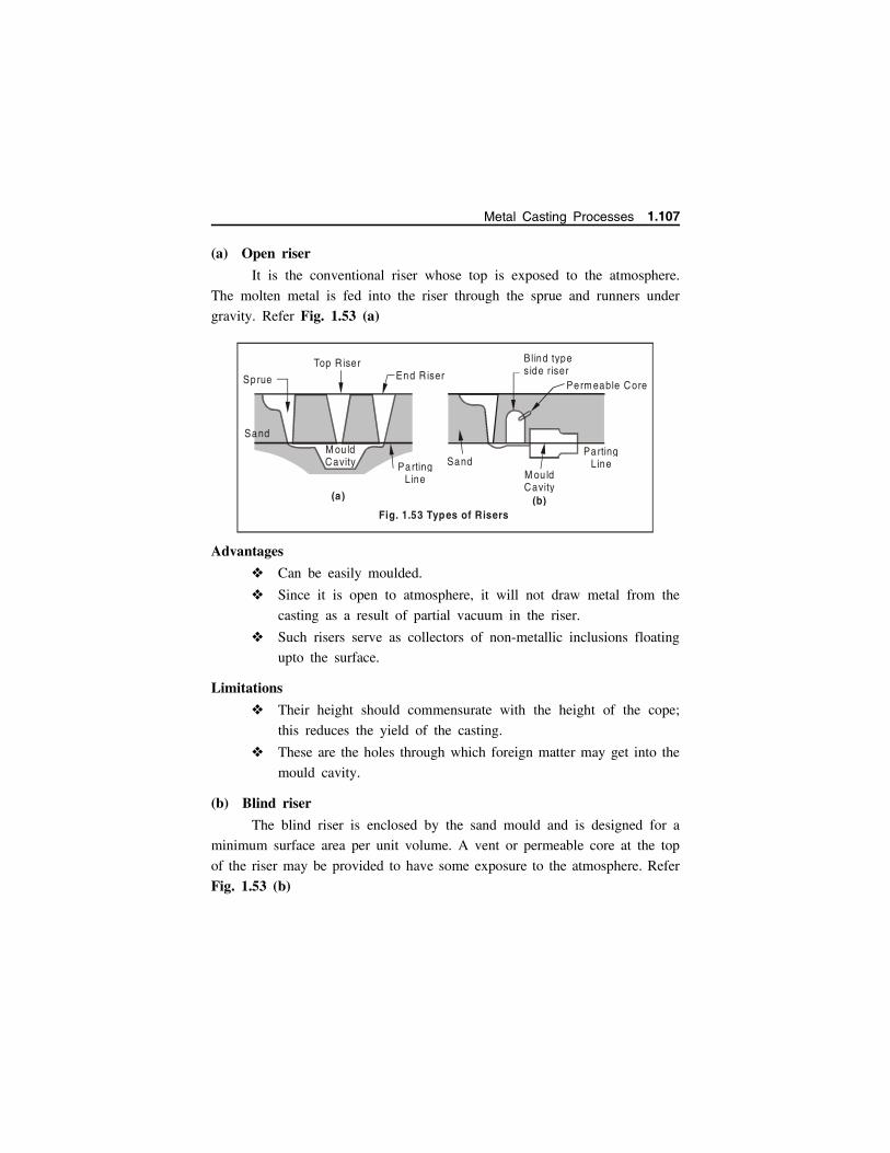
(a) Open riser
It is the conventional riser whose top is exposed to the atmosphere.
The molten metal is fed into the riser through the sprue and runners under
gravity. Refer Fig. 1.53 (a)
Advantages
Can be easily moulded.
Since it is open to atmosphere, it will not draw metal from the
casting as a result of partial vacuum in the riser.
Such risers serve as collectors of non-metallic inclusions floating
upto the surface.
Limitations
Their height should commensurate with the height of the cope;
this reduces the yield of the casting.
These are the holes through which foreign matter may get into the
mould cavity.
(b) Blind riser
The blind riser is enclosed by the sand mould and is designed for a
minimum surface area per unit volume. A vent or permeable core at the top
of the riser may be provided to have some exposure to the atmosphere. Refer
Fig. 1.53 (b)
Sprue
Top R iser End R iser
M ou ld Cavity Parting
L ine
(a)
M ou ldCavity
PartingLine
Blind types ide r iser
Perm eable Core
(b)Fig. 1.53 Types of Risers
Sand
Sand
Metal Casting Processes 1.107
Advantages
Can be removed more easily from the casting than an open riser.
Since a blind riser is surrounded on all sides by moulding sand,
therefore, it looses heat slowly which helps in better directional
solidification of the casting.
It can be smaller than a comparable open riser, therefore, more
yield is obtained.
Limitation
As the metal in it cools, metal skins may quickly form on its walls.
This results in a vacuum in the riser and the riser will not actually draw
metal from the casting. This may be avoided by inserting a permeable dry
sand core into the riser cavity, connecting it to the mould sand layers. Through
these sand layers air passes into the riser interior and thus the riser operates
under atmospheric pressure.
1.13.3 Riser shapeThe metal in the riser should remain in the molten state for a longer
time than in the mould cavity.
The heat loss in the riser should therefore be kept to a minimum level.
It means riser must freeze more slowly than the casting.
Thus their shape should be such as to give volume - to - surface ratio
a maximum value.
From this point of view a spherical shape is ideal one as it is having
the lowest surface area for a same volume.
But risers of spherical shape is difficult to mould. Therefore, a
cylindrical shape is preferred.
Height of a cylindrical riser 1.5 diameter of riser.
1.13.4 Riser sizeThe solidification time of a casting depends upon the heat in the casting
(directly) and depends (inversely) upon the surface area of the casting.
Based on the above facts, the following relations have been suggested
for determining the riser size.
1.108 Manufacturing Technology I - www.airwalkbooks.com
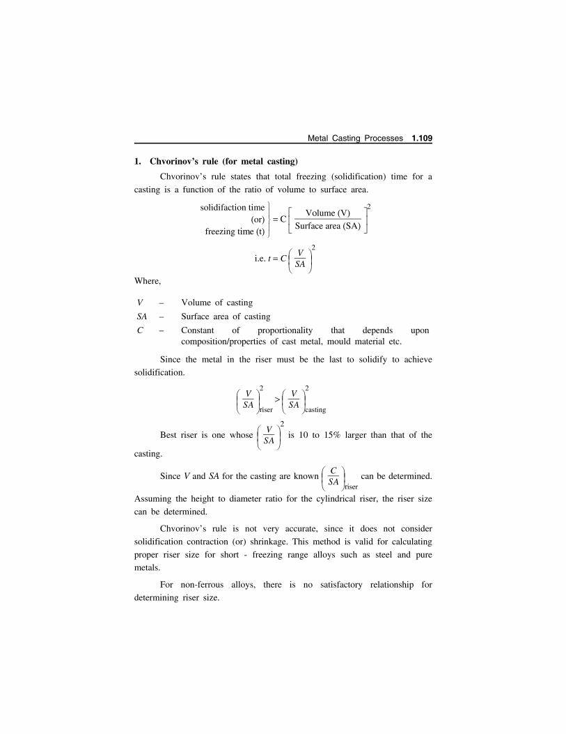
1. Chvorinov’s rule (for metal casting)
Chvorinov’s rule states that total freezing (solidification) time for a
casting is a function of the ratio of volume to surface area.
solidifaction time
orfreezing time t
C
Volume VSurface area SA
2
i.e. t C
VSA
2
Where,
V – Volume of casting
SA – Surface area of casting
C – Constant of proportionality that depends uponcomposition/properties of cast metal, mould material etc.
Since the metal in the riser must be the last to solidify to achieve
solidification.
VSA
riser
2
VSA
casting
2
Best riser is one whose
VSA
2
is 10 to 15% larger than that of the
casting.
Since V and SA for the casting are known
CSA
riser
can be determined.
Assuming the height to diameter ratio for the cylindrical riser, the riser size
can be determined.
Chvorinov’s rule is not very accurate, since it does not consider
solidification contraction (or) shrinkage. This method is valid for calculating
proper riser size for short - freezing range alloys such as steel and pure
metals.
For non-ferrous alloys, there is no satisfactory relationship for
determining riser size.
Metal Casting Processes 1.109

2. Caine’s methodIn this method, riser size calculation size is based on experimentally
determined hyperbolic relationship between relative freezing times and
volumes of the casting and the riser.
Caine’s method states that, if the casting solidifies infinitely rapidly
the riser (feeder) volume should be equal to the solidification shrinkage of
the casting and if the feeder and casting solidify at the same rate, the feeder
should be infinitely large.
Relative freezing time (or) freezing ratio Rx
is given by
Rx SA/V casting
SA/Vriser
Volume ratio Ry
is given as
Ry Vriser
Vcasting
Caine’s formula is given by
Rx a
Ry b c
Where
a freezing characteristic constant for the metal
b Contraction into from liquid to solid
c relative freezing rate of riser and casting
Table 1.1 shows the typical value of a, b and c for commonly used
metals are given below.
Table 1.1
S.No. Cost-metals a b c
1. Grey cast-iron 0.33 0.03 1.00
2. Cast-iron, brass 0.04 0.17 1.00
3. Steel 0.12 0.05 1.00
4. Aluminium 0.10 0.06 1.08
5. Aluminium bronze 0.24 0.17 1.00
6. Silicon bronze 0.24 0.17 1.00
R y
R x
Sound C asting
D efective C asting
Fig. 1.54
1.110 Manufacturing Technology I - www.airwalkbooks.com

Fig. 1.54 shows a typical hyperbolic curve. In order to find the riser
size for a given casting, the diameter and height of the riser are assumed.
After knowing the values of a, b, and c, the values of Rx and Ry are calculated
and plotted on hyperbolic curve figure. In case the values of Rx and Ry meet
the above curve, the assumed riser size is satisfactory, otherwise a new
assumption is made.
1.13.5 Location of the riser
In addition to the shape and size, a riser must be properly located
to obtain a sound casting. Location of riser should be such that
the riser ensures directional solidification. Since the heaviest
section of the casting solidifies last, the riser should be located to
feed this section the heaviest section will now act as a riser for
other sections which are not so heavy or thick.
1.14 PRINCIPLE OF SPECIAL CASTING PROCESSESSand moulds are single purpose moulds as they are completely
destroyed after the casting has been removed from the moulding box. It
becomes therefore obvious that the use of a permanent mould would do a
considerable saving in labour cost of mould making.
1.14.1 Advantages of Special casting techniques over conventional sand casting.
Greater dimensional accuracy with higher metallurgical quality.
High production rates and hence lower production cost (in certain
cases).
Ability to cast extremely thin sections.
Better surface finish on the castings therefore low labour and
finishing costs.
Castings may possess a denser and finer grain structure and posses
higher mechanical properties.
Metal Casting Processes 1.111
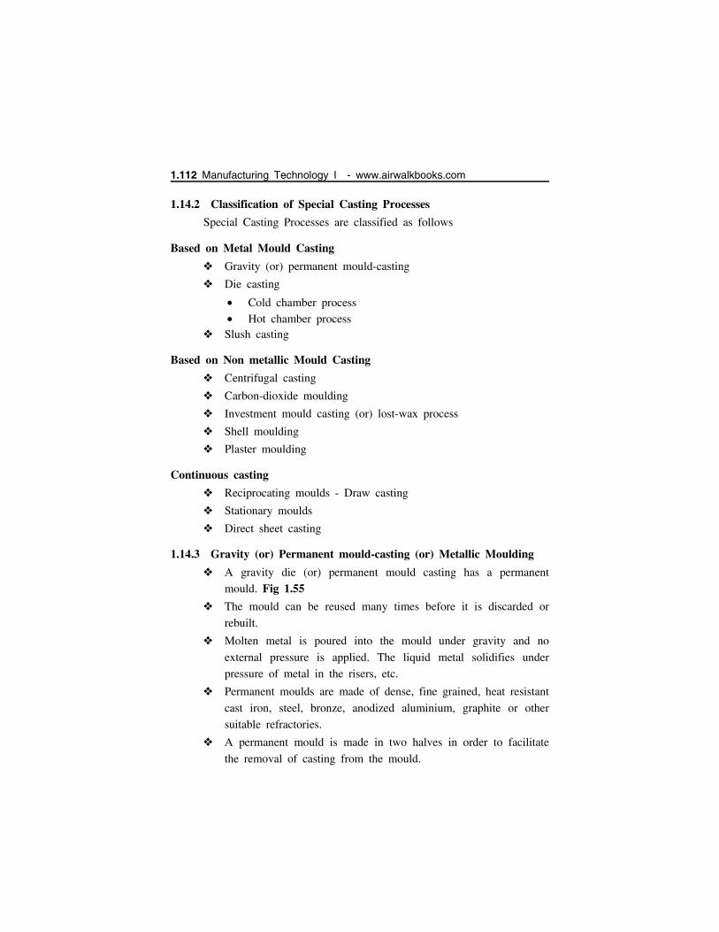
1.14.2 Classification of Special Casting Processes
Special Casting Processes are classified as follows
Based on Metal Mould Casting
Gravity (or) permanent mould-casting
Die casting
Cold chamber process Hot chamber process
Slush casting
Based on Non metallic Mould Casting
Centrifugal casting
Carbon-dioxide moulding
Investment mould casting (or) lost-wax process
Shell moulding
Plaster moulding
Continuous casting
Reciprocating moulds - Draw casting
Stationary moulds
Direct sheet casting
1.14.3 Gravity (or) Permanent mould-casting (or) Metallic Moulding
A gravity die (or) permanent mould casting has a permanent
mould. Fig 1.55
The mould can be reused many times before it is discarded or
rebuilt.
Molten metal is poured into the mould under gravity and no
external pressure is applied. The liquid metal solidifies under
pressure of metal in the risers, etc.
Permanent moulds are made of dense, fine grained, heat resistant
cast iron, steel, bronze, anodized aluminium, graphite or other
suitable refractories.
A permanent mould is made in two halves in order to facilitate
the removal of casting from the mould.
1.112 Manufacturing Technology I - www.airwalkbooks.com
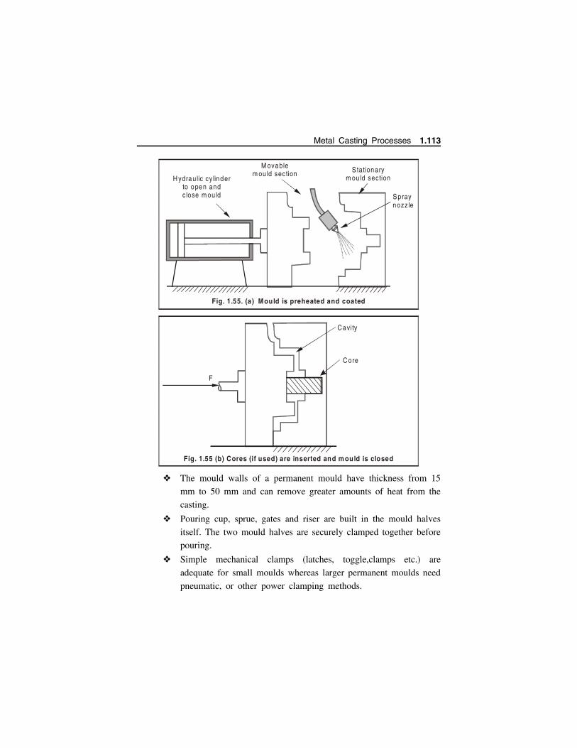
The mould walls of a permanent mould have thickness from 15
mm to 50 mm and can remove greater amounts of heat from the
casting.
Pouring cup, sprue, gates and riser are built in the mould halves
itself. The two mould halves are securely clamped together before
pouring.
Simple mechanical clamps (latches, toggle,clamps etc.) are
adequate for small moulds whereas larger permanent moulds need
pneumatic, or other power clamping methods.
C avity
C ore
F
Fig. 1.55 (b) Cores (if used) are inserted and m ould is closed
Stationarym ou ld section
Spray nozz le
H ydraulic cy linderto open and c lose m ou ld
M ovablem ou ld section
Fig. 1.55. Mould is preheated and coated (a)
Metal Casting Processes 1.113

1.14.3.1 Applications
Permanent mould casting process are costly and is generally limited to
those applications only where an economic or engineering gain is obtained.
Examples are Carburetor bodies, Hydraulic brake cylinders, Refrigeration
castings, Washing machine gears and gear covers, Connecting rods,
automotive pistons, aircraft and missile castings.
1.14.4 Shell mould casting
1.14.4.1 Working Principle
Fig 1.56 Shows the process of Shell mould casting
The 2-piece pattern is made of metal (e.g. aluminum or steel), it
is heated to between 175C 370C and coated with a lubricant,
e.g. silicone spray.
Each heated half-pattern is covered with a mixture of sand and a
thermoset resin/epoxy binder. The binder glues a layer of sand to
the pattern, forming a shell. The process may be repeated to get
a thicker shell.
The assembly is baked to cure it.
The patterns are removed and the two half-shells joined together
to form the mould and then metal is poured into the mould.
F
(c) M olten meta l is poured into the m ould, where it solidifies.
Fig. 1.55. Permanent Mould Casting
1.114 Manufacturing Technology I - www.airwalkbooks.com
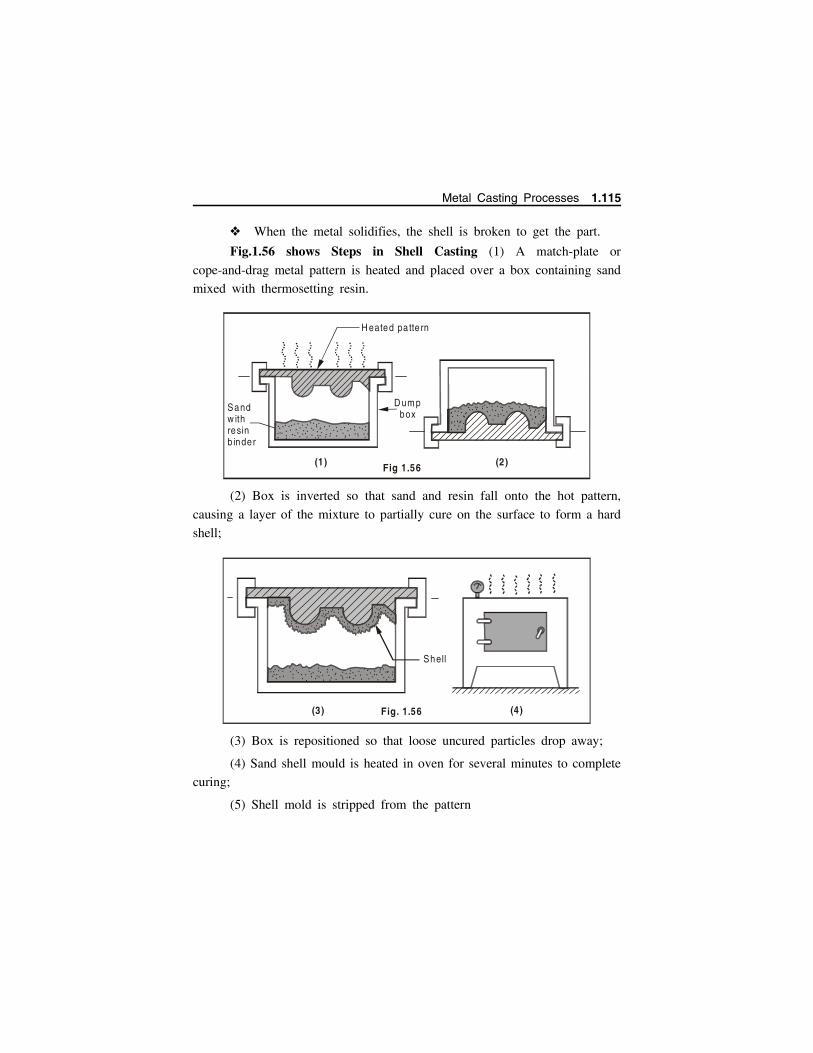
When the metal solidifies, the shell is broken to get the part.
Fig.1.56 shows Steps in Shell Casting (1) A match-plate or
cope-and-drag metal pattern is heated and placed over a box containing sand
mixed with thermosetting resin.
(2) Box is inverted so that sand and resin fall onto the hot pattern,
causing a layer of the mixture to partially cure on the surface to form a hard
shell;
(3) Box is repositioned so that loose uncured particles drop away;
(4) Sand shell mould is heated in oven for several minutes to complete
curing;
(5) Shell mold is stripped from the pattern
(3) (4)
. .. .. .... .... ... . .. .. ... ..
...... ... .. .. .
. .. .... ... ... . . .. .. .
..... ... . . ..
..
..
.
.. . ...... ..
. . .... . ....... . .
. ...
. . . ... . ....
. .. ... . .. ..... ....
.. . . .... ...
. .... .....
.
Shell
Fig. 1.56
Sandw ithresinb inder
D um pbox
H eated pa tte rn
(1)
. . . ...
. .. . . ..
....
. . ... .. ...
...
.....
.. .
..
.... . ... .. .
... .
...
...
.. ...... ... . . . . .....
.. ...... ..... .
... .. .. . ..
.. ... ..
.. ... .. .
. . .. .
. ... ..
..... ..
.......
......
.. . . .
...
(2)Fig 1.56
Metal Casting Processes 1.115

(6) Two halves of the shell mold are assembled, supported by sand or
metal shot in a box and pouring is accomplished.
(7) The finished casting with sprue is removed.
1.14.4.2 Advantages
Castings as thin as 1.5 mm and of high definition can be casted
satisfactorily.
Good dimensional accuracy - machining often not required.
(5)Fig. 1.56
Shell m ou ld
Pa tte rn
... ... ..
....
... ..
.
. . ... . .. .
Shell m oulds M etal shotFlask
(6)
(7)
1.116 Manufacturing Technology I - www.airwalkbooks.com

Mould collapsibility minimizes cracks in casting.
It can be mechanized for mass production.
There is no surface chilling or skin hardening of castings, since
shell is an excellent heat insulator.
Cooling rate of cast metal being slow, castings possess grain sizes
larger than those obtained in green sand moulds.
Shell mould made castings possess excellent surface finish and
high tolerance of the order 0.002 to 0.003 mm per mm is possible.
Shell moulding faithfully reproduces details with sharp clean edges
thereby rendering fettling and machining unnecessary.
Smoother cavity surface permits easier flow of molten metal and
better surface finish.
1.14.4.3 Disadvantages
Shell moulding is uneconomical on small scale production. Resin
costs are comparatively high.
Heavy weight castings weighing greater than 10 kg may not be
able to be casted by shell moulding.
Moulds are not normally economically recoverable.
Shapes in which proper parting and gating cannot be obtained are
not suitable for production with shell moulding process.
The maximum size of the casting is limited by the maximum size
of the shell which can be feasibly produced and poured.
Low carbon steels castings made by shell moulding may show
depressions on their upper surface.
1.14.4.4 Applications
Components cast by shell moulding are: Automotive rocker arms,
valves, small pipes, camshaft, bushings valve bodies, spacers, brackets,
manifolds, bearing caps, shafts and gears.
Shell moulding is ideal for mass production of small castings where
the degree of intricacy causes high rejection rates in green sand
moulding.
Metal Casting Processes 1.117
Various alloys which can be satisfactorily cast by shell moulding
are: aluminium alloys, copper alloys, cast irons, stainless steels etc.
A number of small hydraulic castings in stainless steel and corner
alloys are produced by shell moulding.
Shell moulding is suited to ferrous and non-ferrous alloy castings
in the range 0.1 to 10 kg.
1.14.5 Investment casting (Lost wax casting)
1.14.5.1 Working Principle
Investment casting uses a wax pattern which is coated with refractory
materials to form a mould. The wax is then melted out and the mould cavity
is filled with molten metal. Cast metal is cooled and the slurry broken to get
the castings. It can be used for high precision complex shapes from high
melting point metals that are not readily machinable.
1.14.5.2 Steps involves investment casting
Fig 1.57 shows the step by step method of performing investment
casting.
Pattern creation – (Fig 1.57 (1),(2)) The wax patterns are typically injection moulded into a metal die
and are formed as one piece.
Several of these patterns are attached to a central wax gating
system (sprue, runners, and risers) to form a tree-like assembly.
The gating system forms the channels through which the molten
metal will flow to the mould cavity.
Mould creation – (Fig 1.57 (3),(4),(5)) This "pattern tree" is dipped into a slurry of fine ceramic particles,
coated with more coarse particles and then dried to form a ceramic
shell around the patterns and gating system.
This process is repeated until the shell is thick enough to withstand
the molten metal it will encounter.
1.118 Manufacturing Technology I - www.airwalkbooks.com

Waxpatte rn
(1 )
Waxsprue
(2)(3 )
(4 )
Wax
Heat
(5 ) Heated in oven
(7)
Fig. 1.57 Steps involved in process of Investment casting
Ceram ic partic les
S lurry of fineceramic partic les
Fina lp roduct
Pouring m olten m etal
Metal Casting Processes 1.119
The shell is then placed into an oven and the wax is melted out
leaving a hollow ceramic shell that acts as a one-piece mould,
hence the name “lost wax” casting.
Pouring – (Fig 1.57 (6))
The mould is preheated in a furnace to approximately 1000C and
the molten metal is poured from a ladle into the gating system of
the mould, filling the mould cavity.
Pouring is typically achieved manually under the force of gravity,
but other methods such as vacuum or pressure are sometimes used.
Cooling After the mould has been filled, the molten metal is allowed to
cool and solidify into the shape of the final casting.
Cooling time depends on the thickness of the part, thickness of
the mould and the material used.
Casting removal (Fig 1.57 (7)) After the molten metal has cooled, the mould can be broken and
the casting removed.
The ceramic mould is typically broken using water jets, but several
other methods exist.
Once removed, the parts are separated from the gating system by
either sawing or cold breaking (using liquid nitrogen).
FinishingMost often finishing operations such as grinding or sandblasting are
used to smooth the part at the gates. Heat treatment is also sometimes used
to harden the final part.
1.14.5.3 Applications
Investment casting is used for making components like parts for
sewing machines, locks, rifles, beer barrels and burner, nozzles,
engines, textile cutting machines, motion picture projectors,
pulverizing equipments and chemical industry equipments, dentistry
and surgical implants
1.120 Manufacturing Technology I - www.airwalkbooks.com

To fabricate difficult-to-machine and difficult-to-work alloys into
highly complex shapes such as hollow turbine blades.
For casting jewellery and art castings.
1.14.5.4 Advantages
Parts of greater complexity and intricacy can be cast.
Close dimensional control 0.075 mm.
Good surface finish.
Irregular parts which cannot be machined or difficult to machine
may be cast by investment casting process.
The lost wax can be reused.
Additional machining is not required in normal course.
Al, Cu, Ni, Carbon and alloy steels, tool steels etc. are the common
materials.
Cast does not have disfiguring.
1.14.5.5 Disadvantages
Process is expensive and time consuming (slow).
Pattern making is additional cost.
Size of the casting is limited.
Cores cannot be used
Preferred for casting weight less than 5 kg, maximum dimension
less than 300 mm.
Thickness is usually restricted to 15 mm.
1.14.6 Ceramic Mould Casting
1.14.6.1 Classification of ceramics
Glasses –optical, composite, containers, house hold
Clay products – White ware, bricks
Refractory – Bricks for high temperature (furnaces) Al2O3-SiO2,
ZrO2, Al2O3
Abrasives – Sand paper, cutting and polishing - SiC
Cements – Composites, structural
Metal Casting Processes 1.121
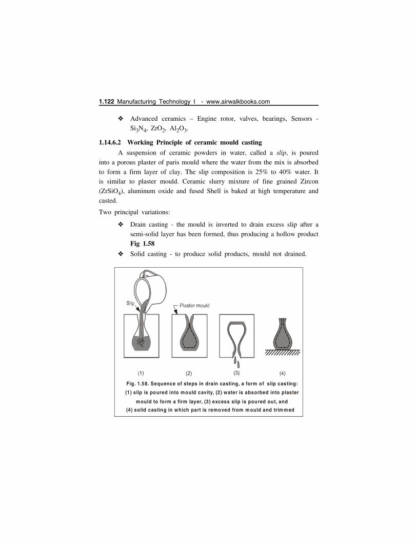
Advanced ceramics – Engine rotor, valves, bearings, Sensors -
Si3N4, ZrO2, Al2O3.
1.14.6.2 Working Principle of ceramic mould casting
A suspension of ceramic powders in water, called a slip, is poured
into a porous plaster of paris mould where the water from the mix is absorbed
to form a firm layer of clay. The slip composition is 25% to 40% water. It
is similar to plaster mould. Ceramic slurry mixture of fine grained Zircon
(ZrSiO4), aluminum oxide and fused Shell is baked at high temperature and
casted.
Two principal variations:
Drain casting - the mould is inverted to drain excess slip after a
semi-solid layer has been formed, thus producing a hollow product
Fig 1.58
Solid casting - to produce solid products, mould not drained.
Fig. 1.58. Sequence of steps in drain casting, a form of slip casting:
(1) slip is poured into mould cavity, (2) water is absorbed into plaster
m ould to form a firm layer, (3) excess slip is poured out, and
(4) solid casting in which part is removed from m ould and trim m ed
1.122 Manufacturing Technology I - www.airwalkbooks.com

1.14.6.3 Applications
High temperature alloys, stainless steel or tool steel parts: examples
impellers, cutters, dies etc.
This process can be used to make very good quality castings of
steel or even stainless steel, it is used for parts such as impellor
blades (for turbines, pumps, or rotors for motor-boats).
1.14.7 Pressure Die Casting
In pressure die casting, molten metal is forced into permanent mould
(die) cavity under pressure. The pressure is generally obtained by compressed
air or hydraulically. The pressure varies from 70 to 5000 Bars and is
maintained while the casting solidifies. Associated with externally applied high
pressure, is the high velocity with which the liquid metal is injected into the
die, and these conditions give a unique capacity for the production of intricate
components at relatively low cost. This process is called simply die casting.
There are four main types of die-casting machine which are given as
under.
1. Hot chamber die casting machine
2. Cold chamber die casting machine.
3. Air blown or goose neck type machine
4. Vacuum die-casting machine
Some commonly used pressure die casting processes are discussed here.
1.14.7.1 Hot chamber die-casting
Hot chamber die-casting machine can produce about 60 or more
castings of up to 20 kg each per hour and several hundred castings per hour
for single impression castings weighing a few grams. The melting unit of
setup comprises of an integral part of the process. This process may be of
gooseneck or air-injection type or submerged plunger type-air blown or goose
neck type machine as shown in Fig. 1.59
It is capable of performing the following functions:
Metal Casting Processes 1.123
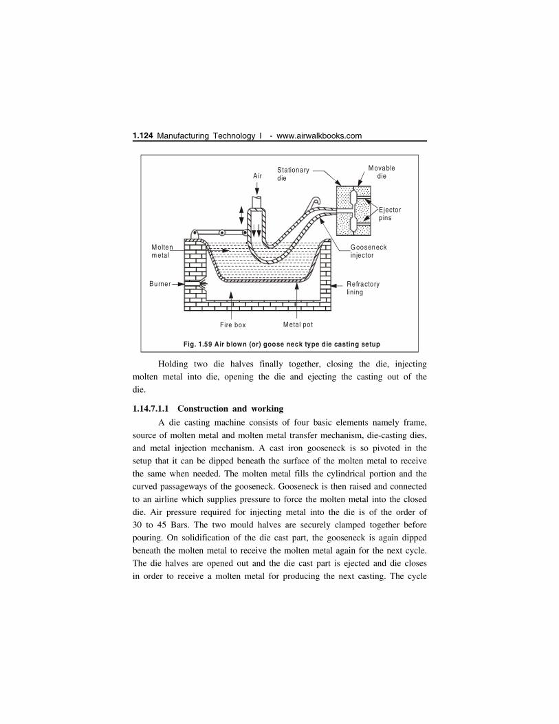
Holding two die halves finally together, closing the die, injecting
molten metal into die, opening the die and ejecting the casting out of the
die.
1.14.7.1.1 Construction and working
A die casting machine consists of four basic elements namely frame,
source of molten metal and molten metal transfer mechanism, die-casting dies,
and metal injection mechanism. A cast iron gooseneck is so pivoted in the
setup that it can be dipped beneath the surface of the molten metal to receive
the same when needed. The molten metal fills the cylindrical portion and the
curved passageways of the gooseneck. Gooseneck is then raised and connected
to an airline which supplies pressure to force the molten metal into the closed
die. Air pressure required for injecting metal into the die is of the order of
30 to 45 Bars. The two mould halves are securely clamped together before
pouring. On solidification of the die cast part, the gooseneck is again dipped
beneath the molten metal to receive the molten metal again for the next cycle.
The die halves are opened out and the die cast part is ejected and die closes
in order to receive a molten metal for producing the next casting. The cycle
. . . . . .. . . . ... . . ........ . . ........ . . ........ . . . ....... . . . ...... .
. . . . . . . . . .. . . . . .. .. . ...... ............ . . . ....... . .. ....... . . ........ .. ...
AirStationarydie
M ovabledie
Ejectorpins
Gooseneckin jector
Refractorylining
M etal potFire box
Burner
M oltenm etal
.. . ... . . . ..... . . . ...... . . .. ....... .. ... .. ... ..... .. ... . .
. .
. .. .. . . ... . . . .. .. . ... . . . .. .. . ....... . . ....
. . . ... . . . ......
Fig. 1.59 Air b lown (or) goose neck type die casting setup
1.124 Manufacturing Technology I - www.airwalkbooks.com
repeats again and again. Generally large permanent moulds need pneumatic
or other power clamping devices. A permanent mould casting may range in
weight from a few grams to 150 kg. for aluminum.
1.14.7.1.2 Applications
Die casting is widely used for mass production and is most suitable
for non-ferrous metals and alloys of low fusion temperature. The
casting process is economic and rapid.
The surface achieved in casting is so smooth that it does not
require any finishing operation.
The material is dense, homogeneous and has no possibility of sand
inclusions or other cast impurities.
Uniform thickness on castings can also be maintained.
The principal base metals most commonly employed in the casting
are zinc, aluminum, copper, magnesium, lead and tin.
Under low category involves zinc, tin and lead base alloys.
Under high temperature category aluminum and copper base alloys
are involved.
1.14.7.2 Cold chamber die casting
Cold chamber die casting process differs from hot chamber die casting
in following respects.
1. Melting unit is generally not an integral part of the cold chamber die
casting machine. Molten metal is brought and poured into die casting
machine with help of ladles and a piston injects metal under high
pressure into die cavity (Fig 1.60)
2. Molten metal poured into the cold chamber casting machine is generally
at lower temperature as compared to that poured in hot chamber die
casting machine.
3. For this reason, a cold chamber die casting process has to be made use
of pressure much higher (of the order of 200 to 2000 Bars) than those
applied in hot chamber process.
4. High pressure tends to increase the fluidity of molten metal possessing
relatively lower temperature.
Metal Casting Processes 1.125

5. Lower temperature of molten metal accompanied with higher injection
pressure will produce castings of dense structure, sustained dimensional
accuracy and free from blow-holes.
6. Die components experience less thermal stresses due to lower
temperature of molten metal. However, the dies are often required to
be made stronger in order to bear higher pressures.
. .... . ....... ............................................ ....... ...... .......................................
Shot chamber
Ram
Ladle
M ovabledie half
Ejectorpins
Cavity
Fixed d ie ha lf
(1)Fig. 1.60
F
(2)
...........................................
........
..................
.......................................................
.
Fig. 1.60 Cycles in cold-chamber casting: (1) W ith die closed and ram withdrawn, m olten m etal is poured into the cham ber
(2) Ram forces m etal to flow into die, m aintain ing pressure during cooling and solidification.
1.126 Manufacturing Technology I - www.airwalkbooks.com
1.14.7.2.1 Advantages
It is a very quick process and is used for mass production with
improved surface finish
Variation in size and shape of the castings is less
Thin section (0.5 mm Zn, 0.8 mm Al and 0.7 mm Mg) can be
easily cast.
Good tolerances with low rejection rate.
Cost of production is less.
Process requires less space.
Life of die is long.
1.14.7.2.2 Disadvantages
Cost of die is high and only thin casting can be produced.
Special skill is required and not suitable for low production.
Unless special precautions are adopted for evaluation of air from
die-cavity, some air is always entrapped in castings causing
porosity.
1.14.7.2.3 Applications
Aluminum, brass and magnesium alloys can be cast.
Low melting-point alloys (zinc, tin, lead) are easy to be cast.
1.14.8 Centrifugal Casting
Centrifugal casting uses a permanent mould that is rotated about
its axis at a speed between 300 to 3000 rpm as the molten metal
is poured.
Centrifugal forces cause the metal to be pushed out towards the
mould walls, where it solidifies after cooling. Parts cast in this
method have a fine grain microstructure, which is resistant to
atmospheric corrosion; hence this method has been used to
manufacture of hollow pipes and other annular shapes.
Since metal is heavier than impurities, most of the impurities and
inclusions are closer to the inner diameter and can be machined
away.
Metal Casting Processes 1.127

Surface finish along the inner diameter is much worse than along
the outer surface.
Centrifugal- casting techniques are usually classified as.
1. True centrifugal casting.
2. Semi-centrifugal casting.
3. Centrifuge casting.
1.14.8.1 True Centrifugal Casting
Molten metal is poured into a rotating mould to produce a tubular
part. In some operations, mould rotation commences after pouring
Fig. 1.61 (a) True centrifugal casting
End view
Free ro lle rM ou ld
M ould
Pouring bas in
Side viewRo lle rs
Fig 1.61 (b)
1.128 Manufacturing Technology I - www.airwalkbooks.com

rather than before. A cylindrical mould is made to rotate on its
own axis at a speed such that the metal being poured is thrown
to the outer surface of the mould cavity. The metal solidifies in
the form of a hollow cylinder (Fig 1.61). The cylinder wall
thickness is controlled by the amount of liquid metal poured.
Casting cools and solidifies from outside, toward the axis of
rotation, thereby providing conditions which set up directional
solidification to produce castings free from shrinkage.
They have more or less a symmetrical configuration (round, square,
hexagonal etc.) on their outer contour and do not need any center
Core.
Advantages
1. Relatively lighter impurities within the liquid metal such as sand, slag,
oxides and gas float more quickly towards the centre of rotation from
where they can be easily machined out thereby giving a clean metal
casting.
2. Dense and fine grained metal castings are produced by true centrifugal
casting techniques.
3. There is proper directional solidification from outside (surface) towards
inwards of the casting.
4. There is no need of a central core or gating system required to make
a pipe or tube.
Disadvantages
1. True centrifugal casting is limited to certain shapes.
2. Equipment costs are high.
3. Skilled workers are required for operation and maintenance.
Applications
Parts such as cast iron pipes, alloy steel pipes, tubing/annular
sections, bushings and rings.
Liners for I.C. Engines, rings, short or long pots and other annular
components.
Metal Casting Processes 1.129

1.14.8.2 Semi-Centrifugal Casting
Centrifugal force is used to produce solid castings rather than tubular
parts Fig.1.62
Moulds are designed with risers at center to supply feed metal.
Density of metal in final casting is greater in outer sections than
at center of rotation.
Often used on parts in which center of casting is machined away,
thus eliminating the portion where quality is lowest.
Advantages1. Semi centrifugal casting ensures purity and density at the extremities of
a casting such as a cast wheel or pulley.
2. Since the poorer structure forms at the center of the casting, it can be
readily machined out if it is objectionable.
Applications
Wheels and pulleys are casted by this process
Po uring bas in
H u b C ore
Straine r C ore
C o pe
C a stin g
D rag
.. . . . . . .. . . . . . .. . . . . . ......... . .. . . . . ..
...
. ...... . ..
.
.
. . . . ..... . . .. .. . ..
. ......... .. .. .... .. .. ... .. .
..
. . . .. ..
. ... . .... .. ......
..... .
. .. .... ... . ...
.
...... .. ..
.....
. ... .....
.....
... . .
..
.
. .. ....... .
. . . ..... . . .. . .. . . .. . .. . . . . . ....
. . . . . .. . . . . .. . . . . ...... ..
....
..... .
..
.. ..
..
.
.
.. .
...
. ..... .. ...
. .....
. .. .
................... . ... ...
. ..... ..... ....
. .... . ....
. .... . ....
. ..... ..... ..... ....
...
. .. ..
...
...
.
..
.. . ... . .. .
... ..
. . ...
. ..
.. .. .. . .. . .
. .. .. . .. . .
.
.. .. . .. . .
... .. ..
. . .... ..
. . ..
..........
.. ....
.. .. . ... .
..
...
...
.. ...
... .
.. ....... .
. . ... ....... .
. . ... ....... .
.. ... ....... . .. .
.. ....... .. . .
.. ....... .
. . ... ....... .
.. .....
.
.
... . . .. . .. .. .. .. .
. .. ..
.... . .
. .. .....
. .. ....... ..
.....
. . . . .
...
.. ...
.. ..... ..
....
.
.
. .. .. . .
. .... .. . .
. .
... .. . .
.. . . . .. . .
. ...
.. . . . . ..
.. .....
. ..
.
. . .. .. ... . . .
. .. ... . . .. .. ...
. . .. .. ...
. . .. .. ...
. . .. .. .... . .
. .. .... . .. .
..... . .
. .. ...
. . .. ...
... . .. .....
..
..... ..... .. . .
. . ..
. . . . .. . ... .
... .. .
. .. .... ..
. .. ..
.. ...... .. .. .... .. .. .... .. .. .... .. .. .... .. .. .... .. .. .... .. .. .... .. .. .... .. .. .... .. .. ....
..........
.
... .. ....
. .. .. ..... .. .. .... .
.. ........
. ..
. ... ..
Sa nd.. .
....
.
sha ft
Fig. 1.62 Semi-centrifugal casting
1.130 Manufacturing Technology I - www.airwalkbooks.com
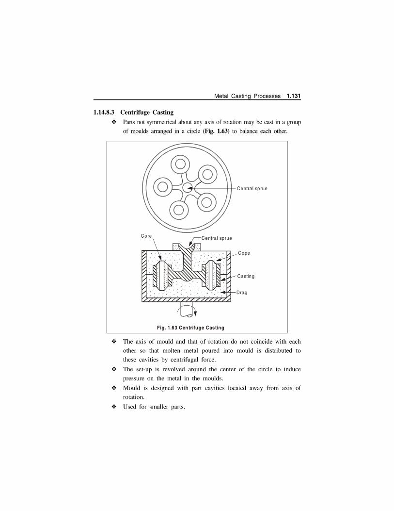
1.14.8.3 Centrifuge Casting
Parts not symmetrical about any axis of rotation may be cast in a group
of moulds arranged in a circle (Fig. 1.63) to balance each other.
The axis of mould and that of rotation do not coincide with each
other so that molten metal poured into mould is distributed to
these cavities by centrifugal force.
The set-up is revolved around the center of the circle to induce
pressure on the metal in the moulds.
Mould is designed with part cavities located away from axis of
rotation.
Used for smaller parts.
. . . . . . . .......... . . . . . . .
... ...
..
... .. .. .. .. .. .. .
..
.. .
. . ... . .
.
.
. ..... .
.
.. .
.. .
. ... .
.... .
...
. .. .
. .. .
. .. .
. .. .. .. . .
.... . . .. .. .
. .. .
. . ... .. .. .. .
. .. .
..
..
Core Central sp rue
Cope
Casting
Drag
Central sp rue
...
................... ...
.. ........ .. ..
. ......
............... .........
........
.................
... .. .. . .... .... . ....
Fig. 1.63 Centrifuge Casting
Metal Casting Processes 1.131

1.14.9 Carbon-dioxide MouldingPrinciple
The highly flowable mixture of pure dry silica sand and sodium
silicate binder is rammed or blown into the mould or corebox.
Carbon-dioxide gas at a pressure of about 1.5 bar is diffused
through the mixture (of sand and sodium silicate) to initiate the
hardening reaction which takes from a few seconds to a few
minutes depending upon the size of core or mould.
Passage of carbon-dioxide through the sand containing sodium
silicate produces carbonic acid in the aqueous solution, this causes
a rise in the SiO2-Na2O ratio and the formation of a colloidal
silica gel which hardens and forms a bond between the sand grains.
This reaction is represented by the following equation
NaSiO3 CO2Sodium Silicate
NaCO3 SiO2Silica gel
1.14.9.1 Operation
The mould material consists of pure dry silica sand (free from
clay) and 3 to 5% sodium silicate liquid (water) base binder,
mulled for about 3 to 4 minutes. The moisture in the mixture is
generally less than 3%.
. . . . .. . .. . . .
.. .. .. .
. . .. . . ......... .. .. ......
. . .... ... .. .CO 2
.. ... ... ... ... . .... . .
Hollow patte rn.
(a) Gassing through hollow pattern
1.132 Manufacturing Technology I - www.airwalkbooks.com

Small amounts of starch or clay may be added to improve green
strength of the mix. Sodium silicate may contain additives such
as sugars to help in breakdown of the core in casting (to improve
collapsibility).
After the moulding mixture has been rammed around the mould
boxes or core boxes by means of hand ramming or machine jolting,
Carbon dioxide gas is forced into the mould or core at about 1.4
to 1.5 Bars. Fig.1.64.
After gassing, core (or) mould is given a refractory coating and
system is ready for pouring.
Core
CO 2
(b) Gassing previously stripped cores
Fig. 1.64. M ethods of gassing m ould and cores
.
.
...
..
..
. ..
. ..
...
. . . . .....
.. .. .
. ...
..
.
...
.
...
.
...
.
...
..
...
..
..
.....
. ..
..
.... .
C O 2
M old
(c) Gassing m ould a fter drawing out pattern
Metal Casting Processes 1.133
1.14.9.2 Advantages
Low cost of production and process can be mechanized.
No skilled labour is required.
Hollow cores can be made easily.
Improved surface finish & dimensional accuracy can be obtained.
Mould hardens quickly and hence metal can be poured frequently.
1.14.9.3 Disadvantages
Reclaim of sand is difficult.
Poor collapsibility and moisture susceptibility to core.
It is less suitable for non ferrous castings.
It is also less suitable for small and thin sections.
1.14.9.4 Applications
It is used for making heavy and thick walled casting, larger cores,
cores for iron, copper and its alloys.
1.14.10 Stir casting
It is an economical process for the fabrication of metal matrixcomposites.
Stir casting is a liquid state method of composite materials fabrication,
in which a dispersed phases - ceramic particles and short fibers are mixed
with a molten matrix metal by means of mechanical stirring. Then the
liquid composite material is cast by conventional casting methods and may
also be processed by conventional metal forming technologies.
There are several parameters in this process, which affect the final
microstructure and mechanical properties of the composites.
Among the variety of manufacturing processes available for
discontinuous metal matrix composites, stir casting is one of the best method
mostly used everywhere. This process is widely used due to its simplicity,
flexibility and applicability to large quantity of production with cost
advantage. The main difficulty in this process is to obtain sufficient wetting
of particle by liquid metal and to get a homogeneous dispersion of the
particles.
1.134 Manufacturing Technology I - www.airwalkbooks.com
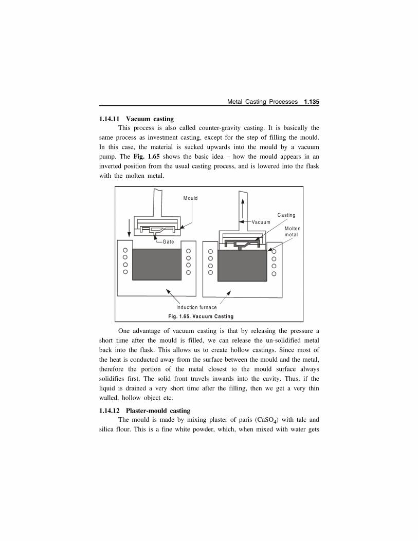
1.14.11 Vacuum castingThis process is also called counter-gravity casting. It is basically the
same process as investment casting, except for the step of filling the mould.
In this case, the material is sucked upwards into the mould by a vacuum
pump. The Fig. 1.65 shows the basic idea – how the mould appears in an
inverted position from the usual casting process, and is lowered into the flask
with the molten metal.
One advantage of vacuum casting is that by releasing the pressure a
short time after the mould is filled, we can release the un-solidified metal
back into the flask. This allows us to create hollow castings. Since most of
the heat is conducted away from the surface between the mould and the metal,
therefore the portion of the metal closest to the mould surface always
solidifies first. The solid front travels inwards into the cavity. Thus, if the
liquid is drained a very short time after the filling, then we get a very thin
walled, hollow object etc.
1.14.12 Plaster-mould castingThe mould is made by mixing plaster of paris (CaSO4) with talc and
silica flour. This is a fine white powder, which, when mixed with water gets
C astingVacuum
M olten m etal
M ou ld
G ate
Induction furnace
Fig. 1.65. Vacuum Casting
Metal Casting Processes 1.135
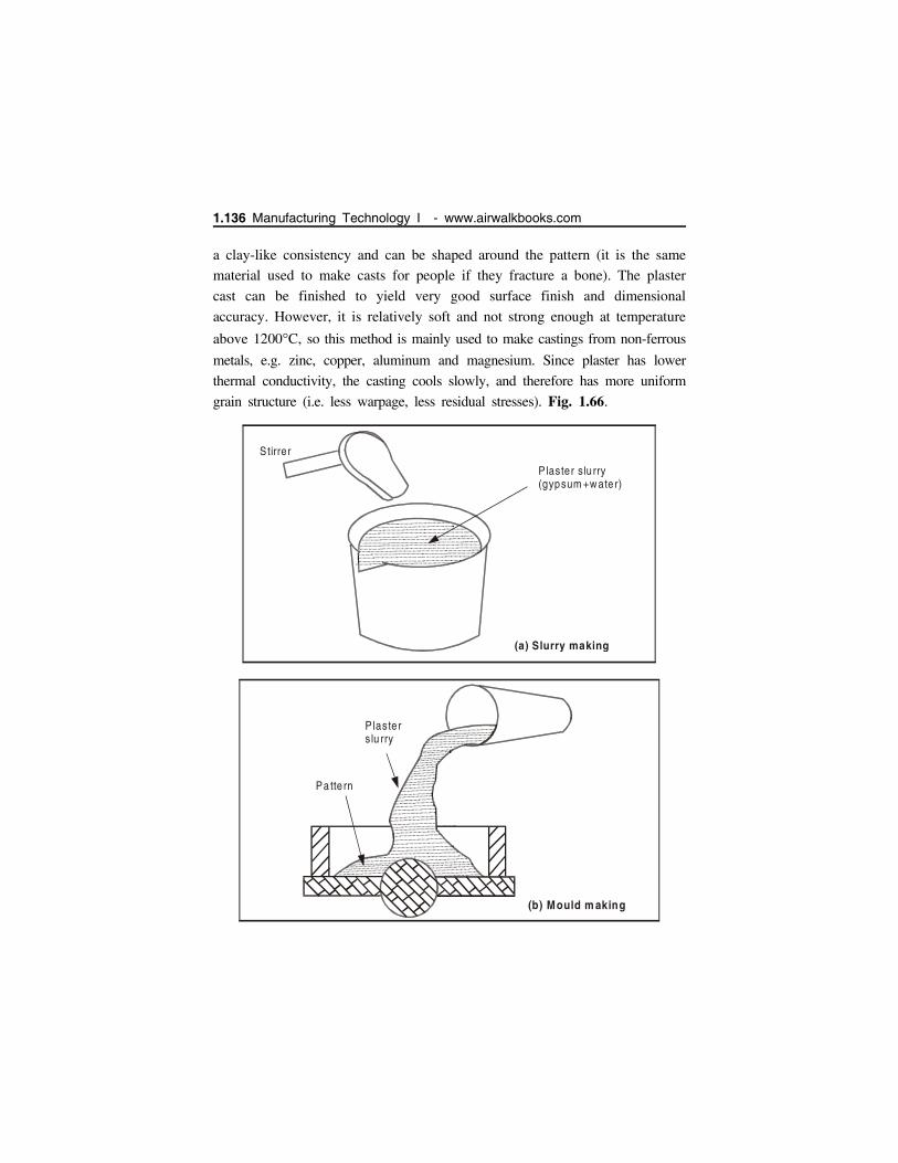
a clay-like consistency and can be shaped around the pattern (it is the same
material used to make casts for people if they fracture a bone). The plaster
cast can be finished to yield very good surface finish and dimensional
accuracy. However, it is relatively soft and not strong enough at temperature
above 1200C, so this method is mainly used to make castings from non-ferrous
metals, e.g. zinc, copper, aluminum and magnesium. Since plaster has lower
thermal conductivity, the casting cools slowly, and therefore has more uniform
grain structure (i.e. less warpage, less residual stresses). Fig. 1.66.
Plaste rs lu rry
Pa tte rn
(b) Mould m aking
Plaster slu rry(gypsum +water)
Stirrer
(a) Slurry making
1.136 Manufacturing Technology I - www.airwalkbooks.com
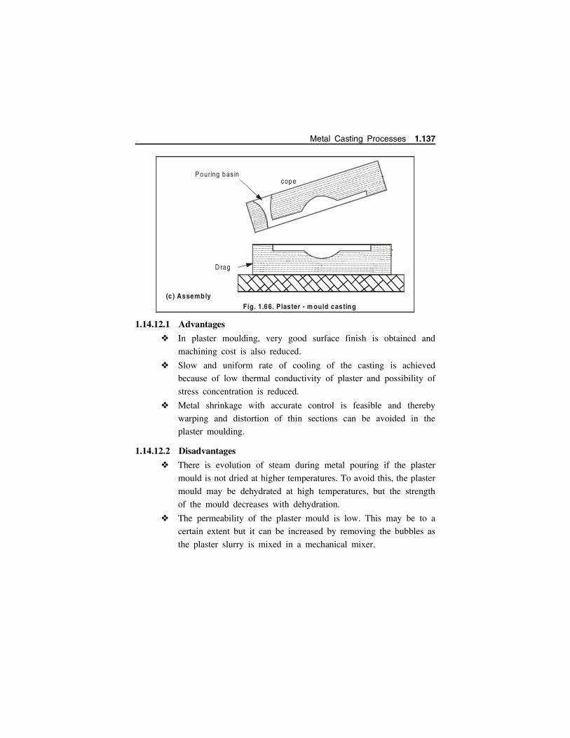
1.14.12.1 Advantages
In plaster moulding, very good surface finish is obtained and
machining cost is also reduced.
Slow and uniform rate of cooling of the casting is achieved
because of low thermal conductivity of plaster and possibility of
stress concentration is reduced.
Metal shrinkage with accurate control is feasible and thereby
warping and distortion of thin sections can be avoided in the
plaster moulding.
1.14.12.2 Disadvantages
There is evolution of steam during metal pouring if the plaster
mould is not dried at higher temperatures. To avoid this, the plaster
mould may be dehydrated at high temperatures, but the strength
of the mould decreases with dehydration.
The permeability of the plaster mould is low. This may be to a
certain extent but it can be increased by removing the bubbles as
the plaster slurry is mixed in a mechanical mixer.
D rag
(c ) Assembly
copePouring bas in
Fig. 1.66. Plaster - m ould casting
Metal Casting Processes 1.137

1.14.13 Expendable-pattern casting (lost foam process)
The pattern used in this process is made from polystyrene (this is the
light, white packaging material which is used to pack electronics inside the
boxes). Polystyrene foam is 95% air bubbles, and the material itself evaporates
when the liquid metal is poured on it. The pattern itself is made by moulding
– the polystyrene beads and pentane are put inside an aluminum mould, and
heated; it expands to fill the mould, and takes the shape of the cavity. The pattern
is removed, and used for the casting process, as follows - The pattern is dipped
in a slurry of water and clay (or other refractory grains), it is dried to get a hard
shell around the pattern. The shell-covered pattern is placed in a container with
sand for support, and liquid metal is poured from a hole on top. The foam
evaporates as the metal fills the shell; upon cooling and solidification, the part
is removed by breaking the shell. Fig 1.67.
The process is useful since it is very cheap, and yields good surface
finish and complex geometry. There are no runners, risers, gating or parting
lines – thus the design process is simplified. The process is used to
manufacture crank-shafts for engines, aluminum engine blocks, manifolds etc.
1.14.14 Continuous Casting
Round ingots, slabs, square billets and sheets can be cast by continuous
process directly from molten metal.
m olten m etal
polystyreneburnsgas escapes
supportsand
patternpolystyrenepattern
.
.. .
.
... . .
.. . .
..
.. . . . . . . .
.. .
..
...
. ...
..
. ..
Fig. 1.67 Expendable-pattern casting (lost foam process)
..
. ...
. . .
. . ..
..
. ...
. . .
. . ..
..
. ...
. . .
. . ..
..
. ...
. . .
. . ..
..
. ...
. . .
. . ..
..
. ...
. . .
. . ..
..
. ...
. . .
. . ..
. ... .
.
. ..
1.138 Manufacturing Technology I - www.airwalkbooks.com

1.14.14.1 Working Principle
Asarco process is one of the most commonly used process and is
shown in Fig. 1.68.
Molten metal is transferred from the holding furnace into special
ladle called a tundish from where the metal is poured into the top
of a bottomless graphite mould of the desired shape.
The process is started by placing a dummy bar in the mould upon
which the first liquid metal falls. The liquid metal gets cooled and
is pulled, by the pinch rolls along with dummy bar.
Vertical cooling chamber cools the hot metal. A skin of solid metal
forms quickly at the mould-metal interface and shrinks from the
mould walls.
Cutting device
Straightening m echanism
W ithdrawal m echan ism
Bendingm echanism
Casting floor(20+m aboveground level)
Lad leTundish
M ould
Vertica l cooling cham ber
M olten m eta l
X-Ray M /c
Fig. 1.68 Continuous casting
Metal Casting Processes 1.139

The shrinking effect provides a very small gap between the metal
and the mould, thereby reducing friction between the two and
permitting cast shape to move continuously through the mould.
Pinch and guide rolls regulate the rate of settling of cast shape
and keep proper alignment.
As the casting passes out of the pinch rolls it is cut to desired
length by a saw or oxyacetylene torch moving briefly along with
the casting. The cut lengths may be straightened, rolled (if desired)
and inspected before shipping.
Argon provides an inert atmosphere to avoid atmospheric
contamination of the molten metal.
X-ray unit controls the pouring rate of molten metal from the ladle.
1.14.14.2 Advantages
Casting surfaces obtained are better than that can be got with static
ingots.
The process is cheaper than rolling from ingots and there is no
need of rough forming and breakdown rolling.
Reduced segregation, grain size and structure of the casting can
be regulated by controlling cooling rates
The casting structure is more dense.
The process is essentially automatic and thus unit labour cost is
low.
100 percent casting yield can be achieved.
1.14.14.3 Applications
It can produce continuous casting of square, rectangle, hexagonal,
fluted, toothed gears, hollow sections.
Production of blooms, billets, slabs and sheets.
Bushings and gears pump.
Copper (wire) bar.
1.140 Manufacturing Technology I - www.airwalkbooks.com
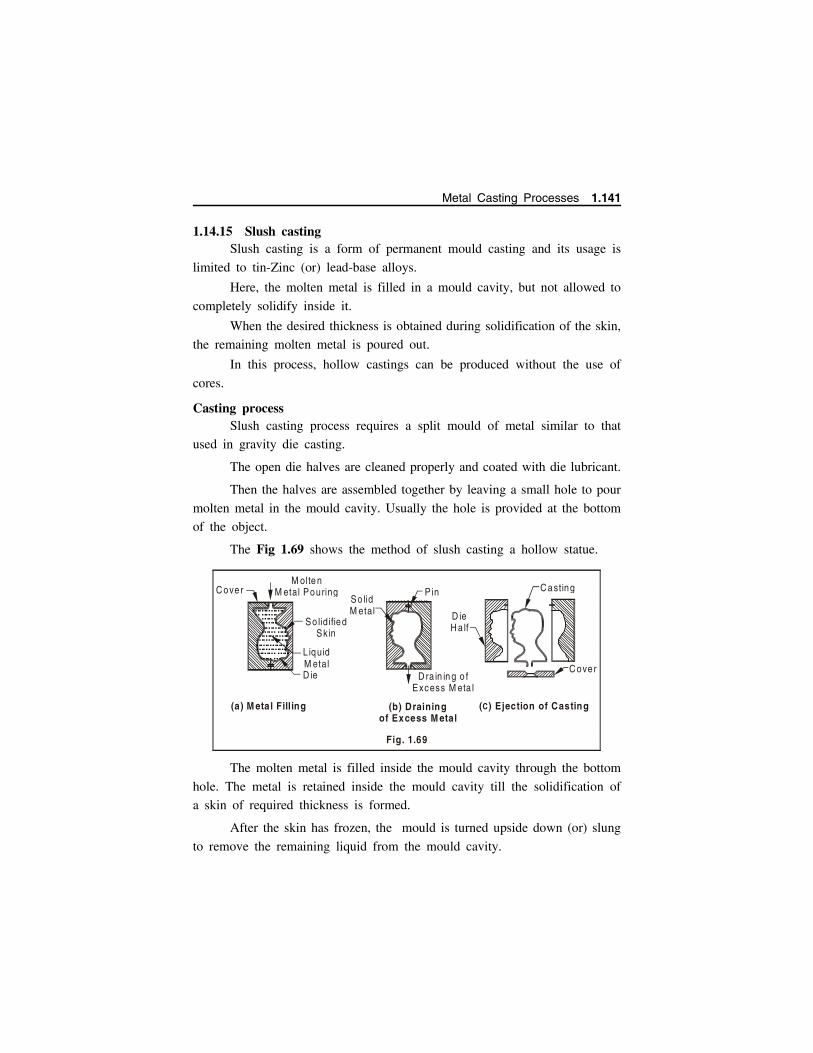
1.14.15 Slush castingSlush casting is a form of permanent mould casting and its usage is
limited to tin-Zinc (or) lead-base alloys.
Here, the molten metal is filled in a mould cavity, but not allowed to
completely solidify inside it.
When the desired thickness is obtained during solidification of the skin,
the remaining molten metal is poured out.
In this process, hollow castings can be produced without the use of
cores.
Casting processSlush casting process requires a split mould of metal similar to that
used in gravity die casting.
The open die halves are cleaned properly and coated with die lubricant.
Then the halves are assembled together by leaving a small hole to pour
molten metal in the mould cavity. Usually the hole is provided at the bottom
of the object.
The Fig 1.69 shows the method of slush casting a hollow statue.
The molten metal is filled inside the mould cavity through the bottom
hole. The metal is retained inside the mould cavity till the solidification of
a skin of required thickness is formed.
After the skin has frozen, the mould is turned upside down (or) slung
to remove the remaining liquid from the mould cavity.
C over M olte n
M etal Pouring
So lidified Sk in
L iquid M etal D ie
(a) M eta l Filling
So lid M etal
P in
D ieH a lf
D ra in in g o f Excess M eta l
(b) Draining of Excess M etal
C asting
C over
(C) Ejection of Casting
Fig. 1.69
Metal Casting Processes 1.141
The mould is kept for some more time to bring the temperature low,
inorder to get sufficient strength for the shell cast.
Finally, the die halves are opened to eject the casting out.
Advantages1. Light and thin castings of hollow shape can be cast successfully.
2. No core is required to form the hollow shape.
3. Intricate shapes like statues ornaments, etc. can be produced using
non-ferrous metals.
4. Very good external surface finish is obtained.
5. The process is applicable in permanent moulds (or) non-metallic
materials also.
6. Cost of production is low.
Limitations1. The thickness of the casting will not be uniform.
2. The internal surface is not smooth and a required internal shape cannot
be obtained.
ApplicationsSluch castings, find wide application in the production of products such
as toys, ornaments and decorative objects like flower vases, bowls, candle
stands, models, etc.
Statues and animal miniatures of non-ferrous metals are generally
produced by slush casting method.
1.15 DESIGN CONSIDERATIONS OF CASTINGS
The design of a cast part should ensure good working characteristics
viz. strength, rigidity, stiffness, tightness and corrosion resistance. Casting
problems can be minimized with proper design done in collaboration between
the designer and the foundry engineer. The important factors in the design
of castings are
Design for
directional solidification
minimum stresses
1.142 Manufacturing Technology I - www.airwalkbooks.com

metal flow
minimum casting
expected tolerances
function
The above are related in general with
the following considerations:
1. Castings should be simple. This reduces
cost.
2. Section thickness of cost part, as far as
possible, should be uniform. This
prevents improper solidification and
shrinkage defects (porosities, cracks,
etc).
3. Complex large castings should be
divided to be easily cast. Then the divided cast parts can be joined to
produce ‘cast-weld’ construction. This prevents wrap (or) tear.
4. Sharp corners and abrupt section changes should be eliminated by
employing fillets and blending radii to prevent stress concentrations
resulting in hot check (or) hot tear. Also smoothly tapered sections
should be used to eliminate high stress concentrations. Refer Fig. 1.71.
Poros ity
Poor
G oo d
(a)
H otTear
Poor
Be tte r (b)Fig. 1.71
Poor
G ood
Best
Fig. 1.70
Metal Casting Processes 1.143
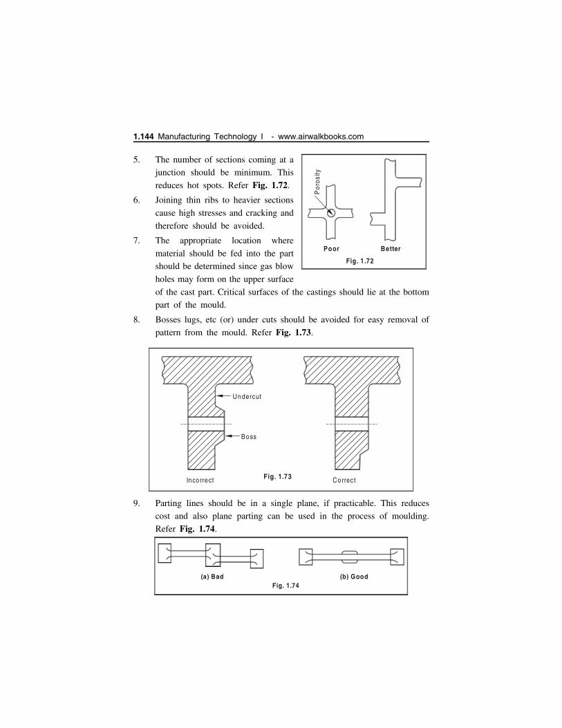
5. The number of sections coming at a
junction should be minimum. This
reduces hot spots. Refer Fig. 1.72.
6. Joining thin ribs to heavier sections
cause high stresses and cracking and
therefore should be avoided.
7. The appropriate location where
material should be fed into the part
should be determined since gas blow
holes may form on the upper surface
of the cast part. Critical surfaces of the castings should lie at the bottom
part of the mould.
8. Bosses lugs, etc (or) under cuts should be avoided for easy removal of
pattern from the mould. Refer Fig. 1.73.
9. Parting lines should be in a single plane, if practicable. This reduces
cost and also plane parting can be used in the process of moulding.
Refer Fig. 1.74.
Boss
Undercut
Inco rrect Correct Fig. 1.73
(a) Bad (b) GoodFig. 1.74
Por
osity
Poor Better
Fig. 1 .72
1.144 Manufacturing Technology I - www.airwalkbooks.com
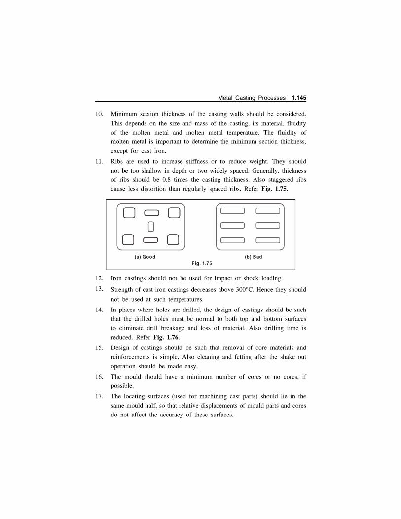
10. Minimum section thickness of the casting walls should be considered.
This depends on the size and mass of the casting, its material, fluidity
of the molten metal and molten metal temperature. The fluidity of
molten metal is important to determine the minimum section thickness,
except for cast iron.
11. Ribs are used to increase stiffness or to reduce weight. They should
not be too shallow in depth or two widely spaced. Generally, thickness
of ribs should be 0.8 times the casting thickness. Also staggered ribs
cause less distortion than regularly spaced ribs. Refer Fig. 1.75.
12. Iron castings should not be used for impact or shock loading.
13. Strength of cast iron castings decreases above 300C. Hence they should
not be used at such temperatures.
14. In places where holes are drilled, the design of castings should be such
that the drilled holes must be normal to both top and bottom surfaces
to eliminate drill breakage and loss of material. Also drilling time is
reduced. Refer Fig. 1.76.
15. Design of castings should be such that removal of core materials and
reinforcements is simple. Also cleaning and fetting after the shake out
operation should be made easy.
16. The mould should have a minimum number of cores or no cores, if
possible.
17. The locating surfaces (used for machining cast parts) should lie in the
same mould half, so that relative displacements of mould parts and cores
do not affect the accuracy of these surfaces.
(a) Good (b) Bad Fig. 1.75
Metal Casting Processes 1.145

18. A thorough analysis of the design should be carried out as the function
of the casting is more important than its cost, ease of manufacture or
appearance.
1.16 DEFECTS IN SAND CASTING
Various defects can develop in manufacturing processes depending on
factors such as materials, part design and processing techniques. While some
defects affect only the appearance of the parts made, others can have major
adverse effects on the structural integrity of the parts. Defects found in
castings may be divided into three classes:
(i) Defects which can be noticed on visual examination or measurement of
the casting.
(ii) Defects which exist under the surface and are revealed by machining,
sectioning or radiography.
(iii) Material defects discovered by mechanical testing of the casting.
Defects in the casting may occur due to one or more of the following reasons:
Fault in design of pattern.
Fault in design of mould and core.
(a ) Bad (b) Good
Fig . 1.76
1.146 Manufacturing Technology I - www.airwalkbooks.com
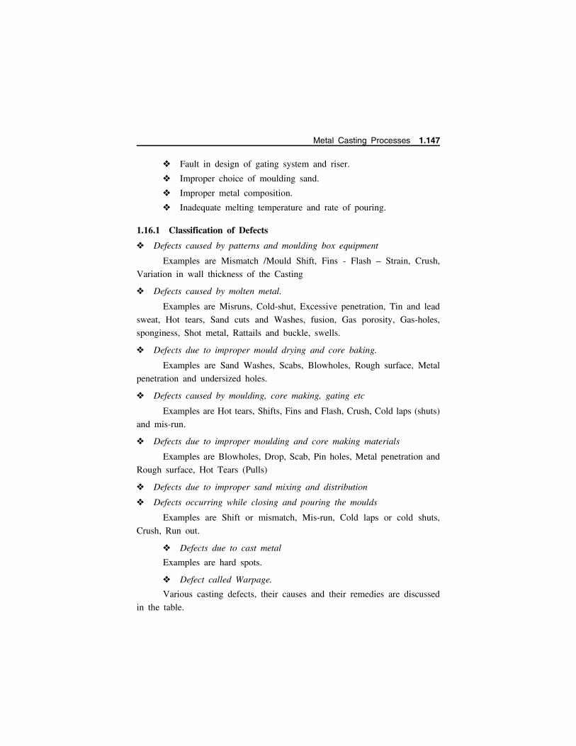
Fault in design of gating system and riser.
Improper choice of moulding sand.
Improper metal composition.
Inadequate melting temperature and rate of pouring.
1.16.1 Classification of Defects
Defects caused by patterns and moulding box equipment
Examples are Mismatch /Mould Shift, Fins - Flash – Strain, Crush,
Variation in wall thickness of the Casting
Defects caused by molten metal.
Examples are Misruns, Cold-shut, Excessive penetration, Tin and lead
sweat, Hot tears, Sand cuts and Washes, fusion, Gas porosity, Gas-holes,
sponginess, Shot metal, Rattails and buckle, swells.
Defects due to improper mould drying and core baking.
Examples are Sand Washes, Scabs, Blowholes, Rough surface, Metal
penetration and undersized holes.
Defects caused by moulding, core making, gating etc
Examples are Hot tears, Shifts, Fins and Flash, Crush, Cold laps (shuts)
and mis-run.
Defects due to improper moulding and core making materials
Examples are Blowholes, Drop, Scab, Pin holes, Metal penetration and
Rough surface, Hot Tears (Pulls)
Defects due to improper sand mixing and distribution
Defects occurring while closing and pouring the moulds
Examples are Shift or mismatch, Mis-run, Cold laps or cold shuts,
Crush, Run out.
Defects due to cast metal
Examples are hard spots.
Defect called Warpage.
Various casting defects, their causes and their remedies are discussed
in the table.
Metal Casting Processes 1.147

surf
ace
of
cast
ing
Blo
w h
ole
1.148 Manufacturing Technology I - www.airwalkbooks.com

Mou
ld Mis
run
Mou
ld
.
..
.. ..
...
.. . .
.. ..
..... ..
.
..
..
..
..
.
.
Por
osity
Metal Casting Processes 1.149

HO
TT
EA
RS
. ....
. . ..... ..
.. .
.... . . ... . .
..... .. . . ... ... .
... .
. . .... . ... .
.. . .. . . ... ..
.. .. .. .. . .. ....
....
..
. .. ..... . .....
..
....
.....
. . .. . ...... .
..
.
Pen
etra
tion
1.150 Manufacturing Technology I - www.airwalkbooks.com
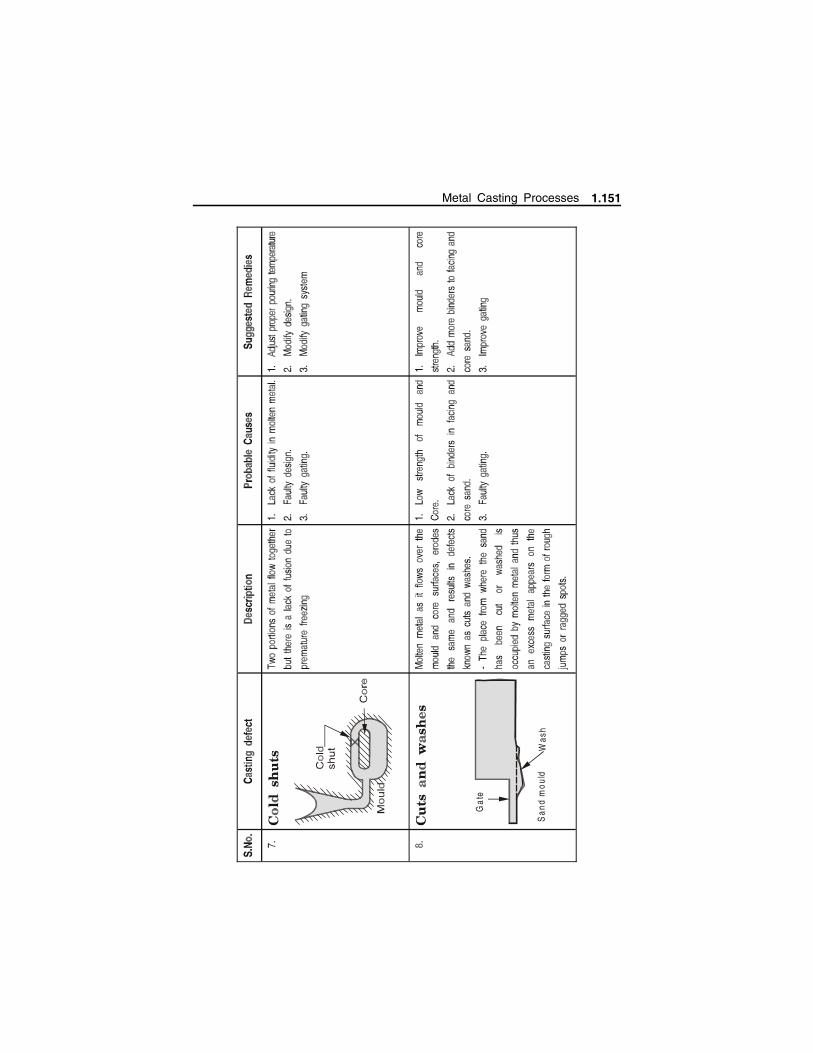
San
d m
ould
Was
h
Gat
e
Metal Casting Processes 1.151

lack
of f
usio
n
1.152 Manufacturing Technology I - www.airwalkbooks.com

Metal Casting Processes 1.153

1.154 Manufacturing Technology I - www.airwalkbooks.com
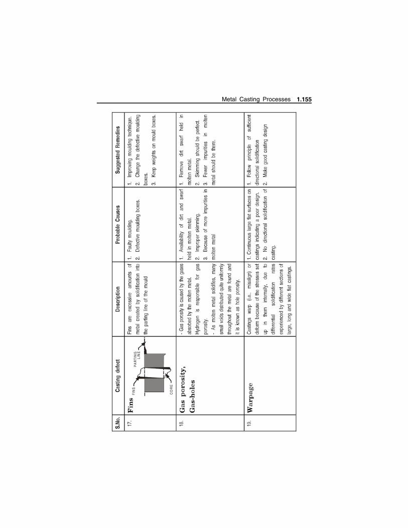
CO
RE
FIN
SP
AR
TIN
GLI
NE
Metal Casting Processes 1.155
1.17 INSPECTION METHOD
Inspection is the act of checking the acceptability of the casting both
dimensionally & functionally. Inspection method is broadly classified into five
categories
Visual inspection
Dimensional inspection
Mechanical Testing
Flaw detection by Non destructive methods
Metallurgical inspection
1.17.1 Visual Inspection
Visual Inspection is carried out for all the castings to detect the
surface defects.
It is carried out either by naked eyes or magnifying glass.
Defects like surface cracks, tears, blow holes, metal penetration,
swells, roughness, shrinkages etc., are easily detected by visual
inspection.
It is the simplest, fastest and most commonly used method for
detecting defects in casting.
It ensures that none of the casting features are eliminated and also
the presence of any modeling errors.
1.17.2 Dimensional inspection
Dimensional Inspection is a very important activity in those
castings which need to be further machined.
It is required for checking out the availability of various machining
allowances in the castings.
It is required in accepting/rejecting of castings.
It is required to check for the correctness of the core, pattern, core
boxes.
It is done by various commercially available instruments like
Micrometer, Gauges, Coordinate measuring machine, 3D inspection
station (Machine vision station).
1.156 Manufacturing Technology I - www.airwalkbooks.com
1.17.3 Mechanical Testing All the castings need to be tested for their mechanical properties
like Tensile/ Compression strength, Hardness, Toughness, Fracture,
Fatigue, Impact testing, Soundness, Pressure/leak testing for tubes
and piping, Creep testing etc.,
All the above tests are done using different commercially available
testing machines like Universal testing machines, Rockwell
hardness testing machines, Fracture testing machines etc. with
standard test procedures.
1.17.4 Flaw detection by Non destructive testing Non-destructive testing is a powerful weapon in foundry industry
with potential for reducing costs, improving product quality, and
maintaining a given quality level. It can play an important role in
improving the competitive position of a casting producer.
The proper nondestructive test, applied at the earliest point in the
production process at which reliable inspection is possible, will
discover defective materials or parts and eliminate further
fabricating costs on units with internal defects.
Non-destructive tests make castings more reliable, safe and
economical.
The most common methods of non-destructive testing used in foundries are:
Radiography (X-ray and -ray).
Fluorescent-Penetrant inspection.
Ultrasonic inspection.
Magnetic particle inspection.
1.17.5 Radiography Test (X-ray (or) -ray) :
The use of X-ray and -ray radiography are used in inspecting castings
for such defects as blow holes, cracks, shrinkage cavities and slag inclusions
.These defects are of special importance in components designed to withstand
high temperatures and pressures employed in power plants, atomic reactors,
chemical and pressure vessels etc., because they cause stress concentration
which may frequently lead to part failure.
Metal Casting Processes 1.157
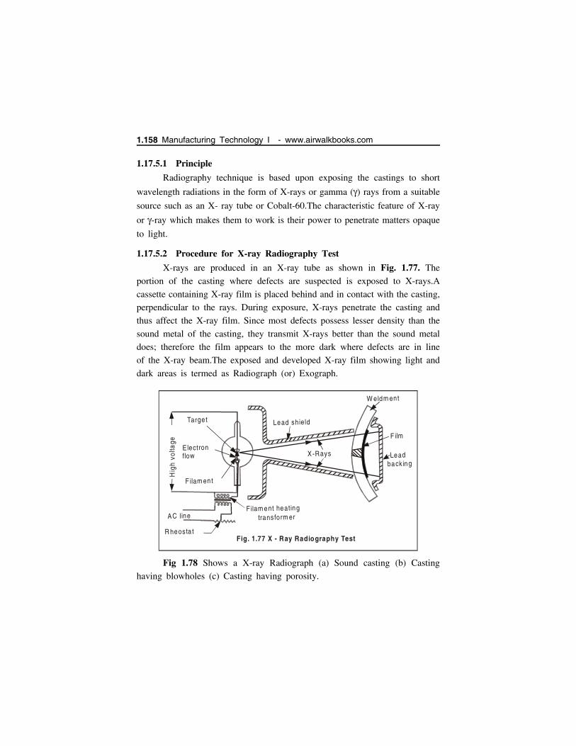
1.17.5.1 Principle
Radiography technique is based upon exposing the castings to short
wavelength radiations in the form of X-rays or gamma () rays from a suitable
source such as an X- ray tube or Cobalt-60.The characteristic feature of X-ray
or -ray which makes them to work is their power to penetrate matters opaque
to light.
1.17.5.2 Procedure for X-ray Radiography Test
X-rays are produced in an X-ray tube as shown in Fig. 1.77. The
portion of the casting where defects are suspected is exposed to X-rays.A
cassette containing X-ray film is placed behind and in contact with the casting,
perpendicular to the rays. During exposure, X-rays penetrate the casting and
thus affect the X-ray film. Since most defects possess lesser density than the
sound metal of the casting, they transmit X-rays better than the sound metal
does; therefore the film appears to the more dark where defects are in line
of the X-ray beam.The exposed and developed X-ray film showing light and
dark areas is termed as Radiograph (or) Exograph.
Fig 1.78 Shows a X-ray Radiograph (a) Sound casting (b) Casting
having blowholes (c) Casting having porosity.
Targe t
Electronflow
F ilam en t
Lead shield
X-Rays
W eldm ent
F ilm
Leadback ing
Filam ent heatingtransform er
R heosta t
AC line
Hig
h v
olta
ge
Fig. 1.77 X - Ray Radiography Test
1.158 Manufacturing Technology I - www.airwalkbooks.com

1.17.5.3 Gamma Ray Radiography Test
It is used for thicker castings.
Scattering of Gamma rays is less and hence are more satisfactory
than X-ray techniques for varying casting thickness.
It is a slower method than X-ray technique.
It can be used to inspect number of casting at a time.
C a stin g
Film
C o -60
Fig. 1.79 Gam m a Ray Radiography
CastingBlow
Ho les
X rayX ray
.... ........... ........ ......
............... ...
.......... . ...........
Po ros ity
X ray
(b )(a ) (c)Fig. 1.78 X-Ray Radiograph
Metal Casting Processes 1.159

Gamma-ray equipment being small possesses better portability and
convenience of use for certain field inspections.
Unlike X-rays, gamma-rays from its source are emitted in all
directions, therefore a number of separate castings having cassette
containing film, fastened to the back of each casting, are disposed
in a circle around the source placed in a central position as shown
in Fig. 1.79.
1.17.6 Magnetic Particle Inspection
This method of inspection is used on magnetic ferrous castings for
detecting invisible surface or slightly subsurface defects. Deeper
subsurface defects are not satisfactorily detected because the
influence of the distorted lines of magnetic flux (owing to a
discontinuity) on the magnetic particles spread over the casting.
Fig 1.80.
1.160 Manufacturing Technology I - www.airwalkbooks.com
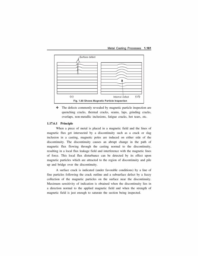
The defects commonly revealed by magnetic particle inspection are
quenching cracks, thermal cracks, seams, laps, grinding cracks,
overlaps, non-metallic inclusions, fatigue cracks, hot tears, etc.
1.17.6.1 Principle
When a piece of metal is placed in a magnetic field and the lines of
magnetic flux get intersected by a discontinuity such as a crack or slag
inclusion in a casting, magnetic poles are induced on either side of the
discontinuity. The discontinuity causes an abrupt change in the path of
magnetic flux flowing through the casting normal to the discontinuity,
resulting in a local flux leakage field and interference with the magnetic lines
of force. This local flux disturbance can be detected by its effect upon
magnetic particles which are attracted to the region of discontinuity and pile
up and bridge over the discontinuity.
A surface crack is indicated (under favorable conditions) by a line of
fine particles following the crack outline and a subsurface defect by a fuzzy
collection of the magnetic particles on the surface near the discontinuity.
Maximum sensitivity of indication is obtained when the discontinuity lies in
a direction normal to the applied magnetic field and when the strength of
magnetic field is just enough to saturate the section being inspected.
Fig. 1.80 Shows M agnetic Particle Inspection
Metal Casting Processes 1.161
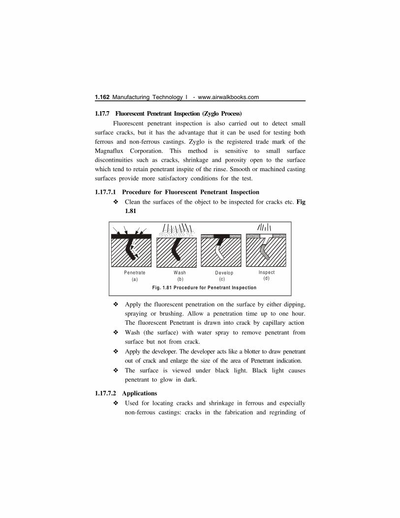
1.17.7 Fluorescent Penetrant Inspection (Zyglo Process)
Fluorescent penetrant inspection is also carried out to detect small
surface cracks, but it has the advantage that it can be used for testing both
ferrous and non-ferrous castings. Zyglo is the registered trade mark of the
Magnaflux Corporation. This method is sensitive to small surface
discontinuities such as cracks, shrinkage and porosity open to the surface
which tend to retain penetrant inspite of the rinse. Smooth or machined casting
surfaces provide more satisfactory conditions for the test.
1.17.7.1 Procedure for Fluorescent Penetrant Inspection
Clean the surfaces of the object to be inspected for cracks etc. Fig1.81
Apply the fluorescent penetration on the surface by either dipping,
spraying or brushing. Allow a penetration time up to one hour.
The fluorescent Penetrant is drawn into crack by capillary action
Wash (the surface) with water spray to remove penetrant from
surface but not from crack.
Apply the developer. The developer acts like a blotter to draw penetrant
out of crack and enlarge the size of the area of Penetrant indication.
The surface is viewed under black light. Black light causes
penetrant to glow in dark.
1.17.7.2 Applications
Used for locating cracks and shrinkage in ferrous and especially
non-ferrous castings: cracks in the fabrication and regrinding of
......... ......................... ... ....... ...................
.. ......... ...... ......... ......................... .. ....... ...................
.. ........ ....
.............................
...............
...............
...... ...............
.... .
.. ... ....
......... ......................... .. ...... ...............
.. ................. ......................... .. ...... ...............
.. ........ ........
Pene tra te(a )
W ash(b )
....... .. . .
.... ..
...
......... ...... ... .. .. ..
.. ....... . ........
...
.. ....... .
...
D eve lo p(c)
Inspect(d )
Fig. 1.81 Procedure for Penetrant Inspection
1.162 Manufacturing Technology I - www.airwalkbooks.com

carbide tools, cracks and pits in welded structures, cracks in steam
and gas turbine blades, ceramic insulators for spark plugs and
electronic applications.
It can also be carried out on parts made up of other materials such as
plastics, ceramics, glass, etc.
1.17.8 Liquid (Dye) Penetrant Test
A liquid penetrant test is non-destructive type and can detect flaws that
are open to the surface e.g. cracks, seams, laps, lack of bond, porosity, cold
shuts etc. It is effectively used in inspection of ferrous metals, non-ferrous
metal products, non-porous, non-metallic materials such as ceramics, plastics
and glass.
1.17.8.1 Working Principle
The principle of liquid penetrant test is that the liquids used enter small
openings such as cracks or porosities by capillary action. The rate and extent
of this action are dependent upon such properties as surface tension, cohesion,
adhesion and viscosity. They are also influenced by factors such as the
condition of the surface of material and the interior of the discontinuity.
For the liquid to penetrate effectively, the surface of the material must
be thoroughly cleaned. After cleaning, the liquid penetrant is applied evenly
over the surface and allowed to remain long enough to permit penetration
into possible discontinuities. The liquid is then completely removed from the
surface of the component and either a wet or a dry developer is applied. The
liquid that has penetrated the defects will then bleed out onto the surface,
and the developer will help delineate them. This will show the location,
general nature and magnitude of any defect present.
The oil-whiting test is one of the older and cruder penetrant tests used
for the detection of cracks too small to be noticed in a visual inspection. In
this method, the piece is covered with penetrating oil, such as kerosene, then
rubbed dry and coated with dry whiting. In a short time the oil that has
seeped into any cracks will be partially absorbed by the whiting, producing
plainly visible discoloured streaks delineating the cracks.
Metal Casting Processes 1.163

1.17.9 Ultrasonic Inspection
1.17.9.1 Principle
Ultrasonic inspection is employed to detect and locate defects such
as shrinkage cavities, internal bursts or cracks, porosity and large
non-metallic inclusions.
Ultrasonic waves are usually generated by the Piezoelectric effect
which converts electrical energy to mechanical energy. A quartz
crystal is used for the purpose.
Ultrasonic inspection for flaw detection makes use of acoustic
waves with frequencies in the range between 20 KHz and 20 MHz,
which can be transmitted through solids (even liquid and air as
well) and get reflected by the subsurface defects. Ultrasonic waves
form a basis for detection, location and size estimation of defects.
1.17.9.2 Steps in Ultrasonic inspection
The surface of casting is made fairly smooth
Ultrasonic inspection employs separate probes, one for transmitting
the waves and other to receive them after passage through the
castings. The ultrasonic waves are transmitted as a series of
intermittent pulses and the same crystal may be employed both as
the transmitter and receiver (Fig. 1.82).
Defect
Soundwave
1 2 3
Casting
Transm itterp robe Receiver
p robe
Input pu lse-p ip
1 Defect echo
CR Oscreen
23
Backecho
Time d is tancescale
(reduced)
Fig. 1.82 Princip le of Ultrasonic Inspection
1.164 Manufacturing Technology I - www.airwalkbooks.com
Before transmitting waves, an oil film is provided between the
probe and the casting surface.
Now an ultrasonic wave is introduced into the metal and the time
interval between transmission of the outgoing and reception of the
incoming signals are measured with a Cathode Ray Oscilloscope
(CRO).
The time base of CRO is so adjusted that the full width of the
trace represents the section being examined.
To start with, as the wave is sent from the transmitter probe, it
strikes the upper surface of the casting and makes a sharp (peak)
or pip (echo) at the left hand side of the CRO screen.
If the casting is sound, this wave will strike the bottom surface
of the casting, get reflected and indicated by a pip towards the
right hand end of CRO screen.
In case a defect exists in between the top and bottom casting
surfaces, most of the beam striking this defect will get reflected
from the defect, reach the receiver probe and indicate a pip (echo)
on the CRO screen, before the pip given by the waves striking
the far end of the casting and returning.
1.17.9.3 Advantages
It is a fast, highly sensitive, economical and reliable method of
non-destructive inspection.
This method of locating flaws with metal objects is more sensitive
than radiography.
Big castings can be systematically scanned for initial detection of
major defects.
1.17.9.4 Limitations
Ultrasonic inspection is sensitive to surface roughness. Since the
as-cast surfaces will in most cases be too rough, some preliminary
machining of castings will be required.
Metal Casting Processes 1.165

In complex castings the interpretation of the CRO trace may not
be easy. Waves reflected from corners or other surfaces may give
a false indication of defects.
1.17.9.5 Applications
Ultrasonic vibrations can be used to locate defects in ferrous and
non-ferrous metallic objects as well as in plastics and ceramics.
Inspection of large castings and forging, for internal soundness,
before carrying out expensive machining operations.
Inspection of moving strip or plate for laminations and thickness.
Routine inspection of locomotive axles ,wheel pins for fatigue
cracks, rails for bolt-hole breaks.
PROBLEMS IN CASTING
Problem 1.1 What will be the solidification (or) freezing time for a 1200mm diameter and 35 mm thick casting of aluminium if the mould constant
is 2.2 sec/mm2
Given
Diameter of casting, d 1200 mm
Height/thickness of casting, h 35 mm
Mould constant, C 2.2 sec/mm2
Solution
Volume of the casting, V 4
d2 h
4
12002 35 39584067.44 mm3
Surface area of the casting, SA 2 4
d2
2 4
12002 2261946.71 mm2
Using chvorinov’s rule,
1.166 Manufacturing Technology I - www.airwalkbooks.com

Solidification time, t
t C
VSA
2
2.2 39584067.442261946.71
2
673.75 sec or 11.23 min. Ans.
Problem 1.2 Two castings of the same metal have the same surface area.One casting is in the form of sphere and other is a cube. What is the ratioof the solidification time for the sphere to that of a cube.
Let, V Volume of casting, and
A Surface area of casting
Also, Asphere Acube ...(Given)
According to Chvorinov’s rule,
Solidification time, t
VSA
2
Ratio of solidification time (or) freezing time for the sphere to that
of cube,
tspherettube
Vsphere
SAcube
2
43
R3
a3
162 R6
9a6 Ans.
Where, R Radius of sphere
a Side of the cube.
Problem 1.3 In a sand mould, a sprue of 220 mm height and 1162 mm2
top area is provided to maintain the flow rate of liquid at
1,738,000 mm3/s. What should be area at the base of down sprue to prevent
aspiration of molten metal? Take g 9815 mm/s2.
Metal Casting Processes 1.167
Given:
h 220 mm Top area = 1162 mm; Flow rate, Q 1,738,000 mm3/s,
g 9815 mm/s2
Solution
Area at the base of down sprue
Velocity is down sprue, v 2gh
2 9815 220 2078.12 mm/s
Area at the base of down sprue to maintain the flow rate,
A Qv
1,738,0002078.12
836.33 mm2
Problem 1.4 An aluminium cube of 13 cm side has to be cast along acylindrical riser of height equal to its diameter. The riser is not insulated onany surface. If the volume shrinkage of aluminium during solidification is 5percent; Find(i) Shrinkage volume of cube on solidification.(ii) Minimum size of the riser so that it can provide the shrinkage volume.
Given:
Side of the aluminium cube, a 13 cm
Diameter of cylindrical riser, d height of riser h
Volume shrinkage of aluminium during solidification = 5%
Solution
Shrinkage volume of cube on solidification
Volume of casting a3 133 2197 cm3
Shrinkage volume 5% 5
100 2197 109.85 cm3
(Normally this shrinkage, depending upon metal, varies from 2.5 to
7.5%)
1.168 Manufacturing Technology I - www.airwalkbooks.com
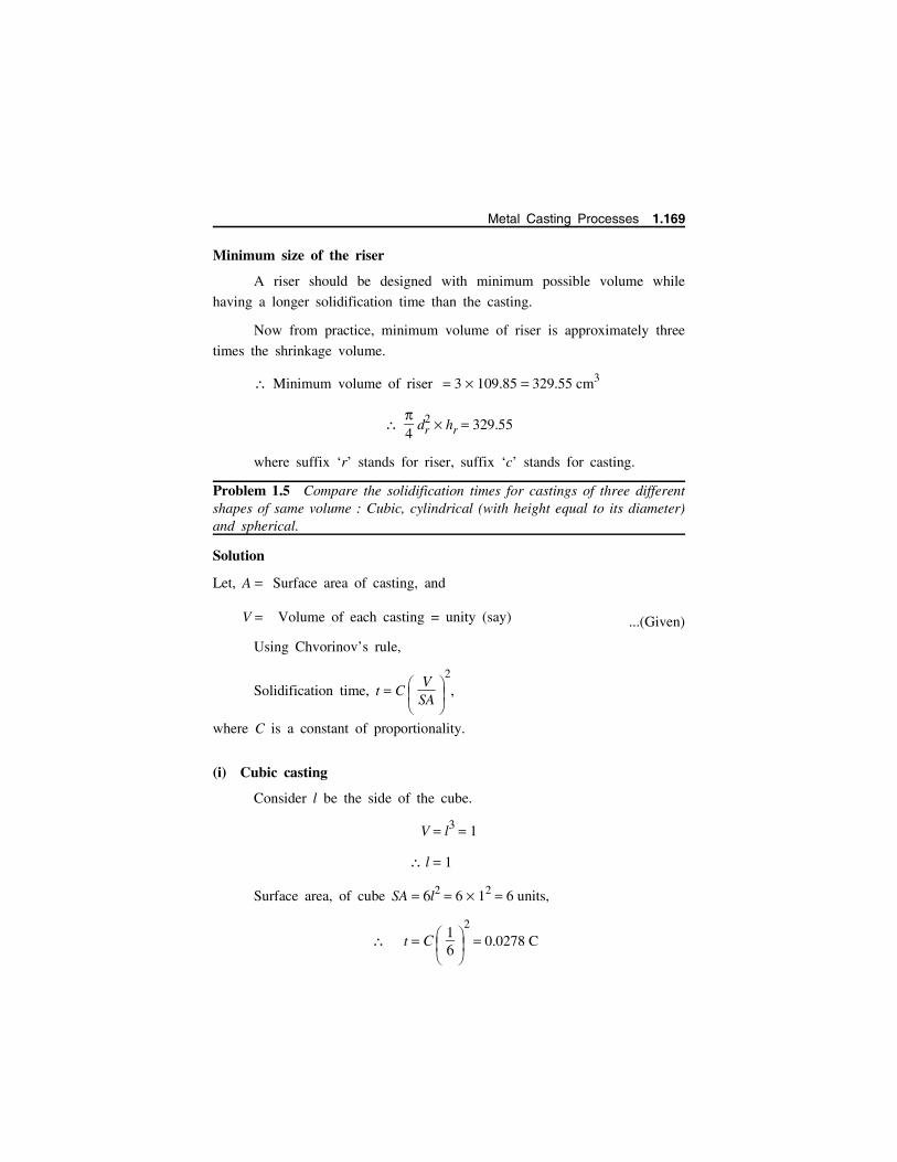
Minimum size of the riser
A riser should be designed with minimum possible volume while
having a longer solidification time than the casting.
Now from practice, minimum volume of riser is approximately three
times the shrinkage volume.
Minimum volume of riser 3 109.85 329.55 cm3
4
dr2 hr 329.55
where suffix ‘r’ stands for riser, suffix ‘c’ stands for casting.
Problem 1.5 Compare the solidification times for castings of three differentshapes of same volume : Cubic, cylindrical (with height equal to its diameter)and spherical.
Solution
Let, A Surface area of casting, and
V Volume of each casting = unity (say) ...(Given)
Using Chvorinov’s rule,
Solidification time, t C
VSA
2
,
where C is a constant of proportionality.
(i) Cubic casting
Consider l be the side of the cube.
V l3 1
l 1
Surface area, of cube SA 6l2 6 12 6 units,
t C 16
2
0.0278 C
Metal Casting Processes 1.169

(ii) Cylindrical casting
Consider r and h be the radius and height of the cylinder.
h 2r
V r2 h r2 2r 1 ...(Given)
(or), 2 r3 1 r
12
1/3
0.5419 unit.
Surface area of the cylinder
SA 2 r2 2 rh
2 r2 2 r 2r 6 r2 6 0.54192 5.53 units
t C
15.53
2
0.0327 C.
(iii) Spherical casting
Consider R be radius of the sphere,
V 43
R3 1 or R
34
1/3
0.62 unit
Surface area of the sphere SA 4 R2 4 0.622 4.83 units
t C
14.83
2
0.0429 C.
Result
Therefore we found that cubic casting has the least solidification time,
hence it will be solidifying at faster rate. Spherical casting has the maximum
solidification time, hence it will solidify at slower rate.
Now, hr dr
4
dr2 dr 329.55 or dr 7.486 cm
...(Given)
1.170 Manufacturing Technology I - www.airwalkbooks.com

In order to have a sound casting, the metal in the riser should be the
last to cool, that is, the riser should have a longer solidification time than
the casting, so
SAV
r
SAV
c
or
VSA
r
VSA
c
,
Now, SAV
r
dh 2
4
d2
4
d2 h
r
d d 2
4
d2
4
d2 d
r
d2
2
d2
4
d3
r
6dr
6
7.486 0.8014
and, SAV
c
6 13 13
13 13 13 0.461
As is clear SAV
r
is SAV
c
, which is not desirable
SAV
r
SAV
c
0.461
or 6dr
0.461,
6
0.461 dr or dr
60.461
or 13
Minimum size of riser = 13 cm diameter 13 cm height.
i.e., {Vr 4
132 13 1725.52 cm3
Metal Casting Processes 1.171