Manufacturing Engineering Technology in SI Units, 6...
52
Manufacturing Engineering Technology in SI Units, 6 th Edition Chapter 22: Cutting-Tool Materials and Cutting Fluids Copyright © 2010 Pearson Education South Asia Pte Ltd Manufacturing Processes (2), IE-352 Ahmed M El-Sherbeeny, PhD Spring 2014
Transcript of Manufacturing Engineering Technology in SI Units, 6...

Manufacturing Engineering Technology in SI Units, 6th Edition Chapter 22:
Cutting-Tool Materials and Cutting Fluids
Copyright © 2010 Pearson Education South Asia Pte Ltd
Manufacturing Processes (2), IE-352 Ahmed M El-Sherbeeny, PhD
Spring 2014
Presenter
Presentation Notes
Presentation slide for courses, classes, lectures et al.

Chapter Outline
1. Introduction 2. Cutting Tool Materials
1. High-speed Steels 2. Cast-cobalt Alloys 3. Carbides 4. Coated Tools 5. Alumina-based Ceramics 6. Cubic Boron Nitride 7. Silicon-nitride-based Ceramics 8. Diamond 9. Whisker-reinforced Materials and Nanomaterials
3. Tool Costs and Reconditioning of Tools 4. Cutting Fluids
Copyright © 2010 Pearson Education South Asia Pte Ltd
2

Introduction
Cutting tool is subjected to –as mentioned before– : 1. High temperatures, 2. High contact stresses 3. Rubbing along the tool–chip interface and along the
machined surface Cutting-tool material must possess: 1. Hot hardness (see right)
compare ceramics vs. carbon steels
2. Toughness and impact strength 3. Thermal shock resistance 4. Wear resistance 5. Chemical stability and inertness (e.g. no adhesion)
3

Introduction
Tool materials -see next 3 slides- may not have all of the desired properties for a particular machining operation:
Hardness, strength: ensure good mechanical properties of workpiece material
Impact strength: important for interrupted cuts (e.g. milling) Melting temperature: important for tool material due to high
temp. generated in cutting zone Physical properties (e.g. thermal conductivity, coefficient of
thermal expansion): ensure tool resistance to thermal fatigue, shock
Compare (for example) in slide 6, High speed steels: high toughness, but low hot hardness Ceramics: high resistance to temp. & wear, but brittle and can chip Diamonds: hardest material, but most expensive
4

Introduction 5

Introduction 6

Introduction 7

Introduction
Tool Materials (also used for dies and molds in casting, forming, and shaping metallic and non-metallic materials):
1. High-speed steels 2. Cast-cobalt alloys 3. Carbides 4. Coated tools 5. Alumina-based ceramics 6. Cubic boron nitride 7. Silicon-nitride-based ceramics 8. Diamond 9. Whisker-reinforced materials and nanomaterials Tools materials are discussed here in terms of:
characteristics, applications, limitations, optimal performance
8

High-speed Steels
High-speed steel (HSS) tools were developed to machine at higher speeds than was previously possible
compared to carbon steels (low hot hardness ⇒low speeds)
Can be hardened to various depths, have good wear resistance and are inexpensive
Suitable for: high +ve rake angle tools, interrupted cuts, machines subject to vibration/chatter, complex tools
Biggest drawback: low cutting speed (V) vs carbide tools Two basic types of HSS:
molybdenum (M-series: 10% Mo; other alloys: Cr, V, W, Co): higher abrasion resistance than T-series, less distortion during heat treatment, less expensive ⇒ comprise 95% of HSS
tungsten (T-series: 12-18% W ; other alloys: Cr, V, Co)
9

High-speed Steels
High-speed steel tools are available in: wrought (rolled or forged) cast powder-metallurgy (sintered) forms
They can be treated to improve performance: Coating (discussed later) Surface treatment (to improve hardness, wear resistance) Steam treatment (reduce tendency of BUE formation)
10
Cast-cobalt Alloys
Cast-cobalt alloys (mostly Co, also: Cr, W): have, high hardness good wear resistance maintain hardness at elevated temperatures (hot hardness)
Drawbacks not as tough as HSS sensitive to impact forces ⇒ less suitable than HSS for interrupted cutting operations
Applications: used as Stellite tools, used for Deep (large t0), roughing cuts (high f & V: twice larger > HSS) Removing large material (little concern for surface finish)
Copyright © 2010 Pearson Education South Asia Pte Ltd
11

Carbides
AKA cemented/sintered carbides (since 1930’s) Characteristics of carbides: 1. High hardness over a wide range of temperatures (&V )
compared to HSS & Cast-Co alloys where only low V possible
2. High elastic modulus 3. High thermal conductivity 4. Low thermal expansion 5. Versatile 6. Cost-effective tool & die materials for many applications 2 groups used in machining (AKA uncoated carbides)
Tungsten Carbide Titanium Carbide
12

Carbides: Tungsten Carbide
Tungsten carbide (WC) consists of tungsten-carbide particles bonded together in a cobalt matrix (i.e. sintering)
particle size is 1-5 μm particles are pressed and sintered into desired “insert” shapes
As Co content increases (typically: 6-16%), strength, hardness, and wear resistance of WC ↓ yet toughness ↑ because of the higher toughness of Co
Applications: Cutting steels, cast irons, abrasive nonferrous materials Have largely replaced HSS due to better performance
Copyright © 2010 Pearson Education South Asia Pte Ltd
13
Carbides: Titanium Carbide
Consists of a nickel–molybdenum matrix wear resistance > tungsten carbide, but is not as tough Applications:
machining hard materials (steels and cast irons) cutting at speeds > those suitable for tungsten carbide
Copyright © 2010 Pearson Education South Asia Pte Ltd
14

Carbides: Inserts
High-speed steel tools (i.e. traditional tools): 1-piece; shaped for applications: drill bits, milling, gear cutters When cutting edge wears ⇒ tool must be replaced and
sharpened, which is a time-consuming and inefficient process
Inserts: individual cutting tools with several cutting points e.g. Square insert: 8 cutting points (how?) Triangular insert: 6 cutting points
15
Typical carbide inserts with various shapes and chip-breaker features; note the complex chip breaking features on inserts
Carbides: Inserts
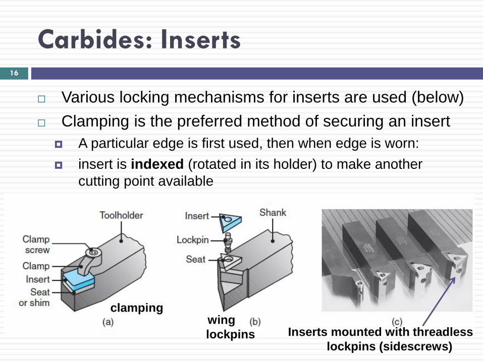
Various locking mechanisms for inserts are used (below) Clamping is the preferred method of securing an insert
A particular edge is first used, then when edge is worn: insert is indexed (rotated in its holder) to make another
cutting point available
16
clamping wing lockpins Inserts mounted with threadless
lockpins (sidescrews)

Carbides: Inserts
Carbide inserts: available in variety of shapes square, triangle, diamond, round (see below)
Strength of insert depends on its shape as included angle of cutting edge ↓⇒ strength of the edge also ↓ and its chipping and breaking ↑
17

Carbides: Inserts
Insert edges are usually honed, chamfered, produced with negative land (see below) this improves edge strength hone radius: about 0.025 mm
18
Carbides: Inserts
Chip-breaker features on inserts (previous chapter) 1. Control chip flow during machining 2. Eliminate long –continuous– chips 3. Reduce vibration and heat generated Selection of chip-breaker feature (slide 15) depends on
f, t0, workpiece material, type of chip, roughing or finishing cut
Stiffness of the machine tool is important small f and V, and chatter are v. harmful to tool cutting edge light f : concentrate forces & temp. at tool edge ⇒ chipping small V ⇒ cold welding of chip to tool ⇒ cutting fluids needed in large, continuous amounts to
minimize heating and cooling in interrupted cutting
19

Carbides: Classification of Carbides
ISO (International Organization for Standardization): standards for carbide grades: classified using letters P, M, K difficult task due to various machining applications, materials
ANSI: other classification (C1-C8), depending on material
20

Coated Tools
New alloys and engineered materials developed to have high strength and toughness (since 1960’s) problem: abrasive, chemically reactive with tool materials Difficulty in machining these materials ⇒ rise of coated tools
Coatings have unique properties: 1. Lower friction 2. Higher adhesion 3. Higher resistance to wear and cracking 4. Acting as a diffusion barrier 5. Higher hot hardness and impact resistance
Copyright © 2010 Pearson Education South Asia Pte Ltd
21
Coated Tools
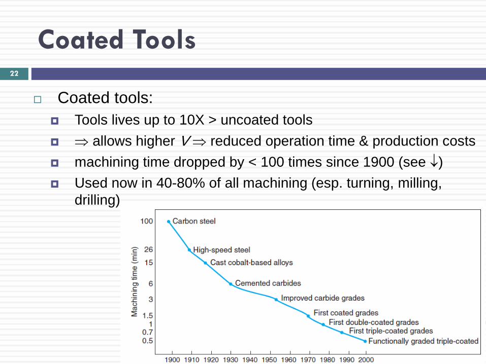
Coated tools: Tools lives up to 10X > uncoated tools ⇒ allows higher V ⇒ reduced operation time & production costs machining time dropped by < 100 times since 1900 (see ↓) Used now in 40-80% of all machining (esp. turning, milling,
drilling)
Copyright © 2010 Pearson Education South Asia Pte Ltd
22

Coated Tools: Coating Materials and Coating Methods
Common coating materials are: 1. Titanium nitride (TiN) 2. Titanium carbide (TiC) 3. Titanium carbonitride (TiCN) 4. Aluminum oxide (Al2O3) Coatings usually have sizes: 2-15 µm
Copyright © 2010 Pearson Education South Asia Pte Ltd
23

Coated Tools: Coating Materials and Coating Methods
Techniques for applying coating on cutting tools & inserts: 1. Chemical-vapor deposition (CVD)
used most with multiphase coating & ceramic tools (later)
2. Physical-vapor deposition (PVD) PVD-coated carbides with TiN coating ⇒ Higher cutting-edge strength Lower friction Lower tendency to form BUE Smoother and more uniform thickness (2-4 µm) (note, how this covers all aspects of higher machinability in last chapter)
Copyright © 2010 Pearson Education South Asia Pte Ltd
24

Coated Tools: Coating Materials and Coating Methods
Coatings for tools should have following characteristics: 1. High hardness: at high temp ⇒ resist wear 2. Chemical stability and inertness to workpiece ⇒ resist
wear 3. Low thermal conductivity: ⇒ prevent rise in tool temp. 4. Compatibility and good bonding to substrate (i.e. tool
material) ⇒ prevent flaking 5. Little or no porosity in coating ⇒ high strength and
integrity Additional enhancements to coating:
Using substrate with high hardness, toughness Honing cutting edges to avoid peeling of coating at edges
25

Coated Tools: Coating Materials and Coating Methods
Titanium-nitride Coatings Have low friction coefficients, high hardness, resistance
to high temperature, and good adhesion to substrate Improve the life of high-speed steel tools and improve
the lives of carbide tools, drill bits, and cutters Perform well at higher cutting speeds and feeds Flank wear « in uncoated tools
(see right) Flank surface can be reground
after use without removing coating on rake face
Copyright © 2010 Pearson Education South Asia Pte Ltd
26

Coated Tools: Coating Materials and Coating Methods
Titanium-carbide Coatings Coatings have high flank-wear resistance in machining
abrasive materials (used with WC inserts)
Ceramic Coatings Ceramic serve well as coating material since
chemically inert have low thermal conductivity, resist high temperature, resist flank and crater wear
Copyright © 2010 Pearson Education South Asia Pte Ltd
27
Presenter
Presentation Notes
WC: Tungsten Carbide
Coated Tools: Coating Materials and Coating Methods
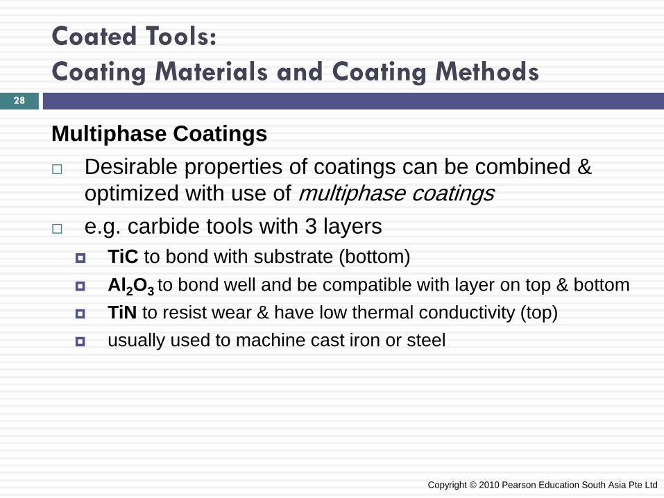
Multiphase Coatings Desirable properties of coatings can be combined &
optimized with use of multiphase coatings e.g. carbide tools with 3 layers
TiC to bond with substrate (bottom) Al2O3 to bond well and be compatible with layer on top & bottom TiN to resist wear & have low thermal conductivity (top) usually used to machine cast iron or steel
Copyright © 2010 Pearson Education South Asia Pte Ltd
28

Coated Tools: Coating Materials and Coating Methods
Alternating Multiphase Coatings Size of each coating layer: 2-10 µm Note, thinner coating ⇒ grain size ↓ ⇒ hardness ↑ Inserts can have as many as 13 alternating layers
Copyright © 2010 Pearson Education South Asia Pte Ltd
29
TiN: low friction Al2O3: therm. stability TiCN: resists flank + crater wear

Coated Tools: Miscellaneous Coating Materials
Polycrystalline diamond coating used especially with WC and SiN inserts used to machine abrasive, nonferrous metals (e.g. Al)
Titanium carbonitride (TiCN) and titanium-aluminum nitride (TiAlN): effective in cutting stainless steels
Chromium carbide (CrC) used to machine softer metals that adhere to cutting tool (e.g. Al, Cu, Ti)
More recent developments are nanolayer coatings and composite coatings
Hardness almost as high as cBN Still in experimental phase Expected to have wide applications in machining
Copyright © 2010 Pearson Education South Asia Pte Ltd
30

Coated Tools: Ion Implantation
Ions are introduced into the surface of the cutting tool, improving its surface properties
Process does not change the dimensions of tools Nitrogen-ion implanted carbide tools have been used
successfully on alloy steels and stainless steels
Copyright © 2010 Pearson Education South Asia Pte Ltd
31

Alumina-based Ceramics
Ceramic tool materials consist of fine-grained and high-purity aluminum oxide additions of titanium carbide and zirconium oxide improve
toughness and thermal shock resistance ceramic inserts used in high-speed cutting (e.g. turning)
Alumina-based ceramic tools high abrasion resistance and hot hardness (see below) more inert than HSS &
carbides ⇒ less BUE (?) ⇒ produce good surface
finish with cast iron have low toughness ⇒
tend to chip prematurely Copyright © 2010 Pearson Education South Asia Pte Ltd
32

Alumina-based Ceramics
Cermets Introduced in 1960’s Consist of ceramic particles in a metallic matrix e.g. cermet: 70% Al2O3 + 30% TiC Have high chemical stability and resistance to BUE
formation But they are brittle, expensive and have limited usage Performance is between ceramics and carbides Application: high-speed finishing cuts
Copyright © 2010 Pearson Education South Asia Pte Ltd
33

Cubic Boron Nitride
Cubic boron nitride (cBN): hardest material after diamond Carbide (substrate) provides shock resistance cBN layer provides v. high wear resistance & cutting-edge
strength
At high temperatures, it is chemically inert to Fe & nickel Its resistance to oxidation is high Suitable for cutting hardened ferrous and high-temp
alloys, and for high-speed machining But: brittle, so
machine must be stiff to resist vibrations
Copyright © 2010 Pearson Education South Asia Pte Ltd
34

Silicon-nitride-based Ceramics
Silicon-nitride (SiN) based ceramic tool materials consist of silicon nitride with various additions of aluminum oxide, yttrium oxide and titanium carbide
Tools have: high toughness hot hardness good thermal-shock resistance
Due to chemical affinity to iron at elevated temperature, SiN-based tools are not suitable for machining steels
Copyright © 2010 Pearson Education South Asia Pte Ltd
35
Diamond
Diamond: hardest of all known substances Properties:
low friction high wear resistance ability to maintain a sharp cutting edge result in good surface finish and high dimensional accuracy best used with soft nonferrous alloys also used with abrasive nonmetallic and metallic materials
Synthetic or industrial diamonds are used since natural diamond has flaws and performance can be unpredictable
Copyright © 2010 Pearson Education South Asia Pte Ltd
36

Diamond
As diamond is brittle, tool shape and sharpness are important
low rake angle must be used to provide strong cutting edge proper mounting should be used for optimum tool life best used with light, uninterrupted finishing cuts tool must be resharpened as soon as it becomes dull (to
minimize fracture
Copyright © 2010 Pearson Education South Asia Pte Ltd
37
top row: Inserts with polycrystalline cBN tips bottom row: Solid polycrystalline cBN inserts Note: these are similar to diamond tools

Whisker-reinforced Materials and Nanomaterials
Continuous effort to improve tool performance, increase wear resistance, and enhance properties:
1. High fracture toughness 2. Resistance to thermal shock 3. Cutting-edge strength 4. Creep resistance 5. Hot hardness Whiskers: used for reinforcing fibers in composite tools
e.g. Si-carbide whiskers: 5-100 µm long, diameter: 0.1-1 µm
Nanomaterials: also becoming important in tools e.g. carbides, ceramics; applied as thin coating Increase tool life without coolant (i.e. dry machining)
38

Tool Costs and Reconditioning of Tools
Tool costs depend on: tool material, size, shape, chip-breaker features and quality; e.g. (12.5-mm insert):
uncoated carbide: $5-10 (cheapest) diamond-tipped: $90-125 (most expensive)
Cost of individual insert is relatively insignificant tooling comprises only 2-4% of all machining costs reason: single tool can be indexed and recycled e.g. square insert with 1 edge lasting 30-60 min will last: ?*
Cutting tools can be reconditioned by resharpening carried out manually, or cutter grinders, or comp.-controlled
Reconditioning of coated tools also done by recoating must make sure dimensions are same as original tool
39
Presenter
Presentation Notes
See slide 60 of previous chapter: 30-60 min for carbide tools Square insert will last: ~ 45 min * 8 edges = 360 min i.e. ~ 6 hours before replacement
Cutting Fluids
Cutting fluids used to: 1. Reduce friction & wear (⇒ improve tool life, surface finish) 2. Cool the cutting zone (⇒ improve tool life, ↓ temperature) 3. Reduce forces and energy consumption 4. Flush chips from cutting zone (important in drilling) 5. Protect machined surface from environmental corrosion Cutting fluid used as (depending on machining operation):
coolant, or lubricant, or both e.g. water: excellent coolant (i.e. temp ↓); but not effective
lubricant (i.e. no ↓ in friction); may also cause oxidation (rust)
Effectiveness of cutting fluids depends on: machining operation, tool & workpiece materials, cutting speed
40

Cutting Fluids
Cutting-fluid Action Cutting fluids move to tool-chip interface by
Seeping (i.e. slow penetration) from sides of the chip capillary action of the “interlocking network of surface
asperities” (i.e. unevenness) in the interface
Cutting fluids should thus have Small molecular size (for small capillary network) Appropriate “wetting” (high surface tension) e.g. using emulsions, low-weight oils suspended in water
Discontinuous cutting operations: have easier mechanisms for lubricant application but the tools are more susceptible to thermal shock
Copyright © 2010 Pearson Education South Asia Pte Ltd
41

Cutting Fluids
EXAMPLE 22.2 Effects of Cutting Fluids on Machining A machining operation is being carried out with a cutting fluid that is an effective lubricant. What will be the changes in the mechanics of the cutting operation if the fluid is shut off?
Copyright © 2010 Pearson Education South Asia Pte Ltd
42

Cutting Fluids
Solution Effects of Cutting Fluids on Machining Chain of events taking place after the fluid is shut off: 1. Friction at the tool–chip interface will increase 2. The shear angle will decrease in accordance 3. The shear strain will increase 4. The chip will become thicker 5. A built-up edge is likely to form
Copyright © 2010 Pearson Education South Asia Pte Ltd
43

Cutting Fluids
Solution Effects of Cutting Fluids on Machining As a result of these changes: 1. The shear energy in the primary zone will increase 2. The frictional energy in the secondary zone will
increase 3. The total energy will increase 4. The temperature in the cutting zone will rise 5. Surface finish will deteriorate and dimensional
tolerances may be difficult to maintain
Copyright © 2010 Pearson Education South Asia Pte Ltd
44

Cutting Fluids
Types of Cutting Fluids (4 general types) 1. Oils (AKA straight oils)
mineral, animal, vegetable, compounded, and synthetic oils used for: low-speed operations (i.e. no high ↑ in temperature)
2. Emulsions (AKA soluble oils) mixture of oil and water and additives used for: high-speed operations (i.e. high ↑ in temperature) water: acts as coolant; oils: reduces oxidation caused by water
3. Semisynthetics chemical emulsions + little water-diluted mineral oil + additives
4. Synthetics chemicals with additives, water-diluted, with no oil
45

Cutting Fluids 46
Methods of Cutting-fluid Application 4 basic methods 1. Flooding
Most common method (see next slide) Typical rate: 10 L/min (single-point tools, as in turning) to
225 L/min (multiple point cutters, as in milling) Chips flushed with 700-14,000 kPa pressures
2. Mist Similar to spraying with aerosol can Allows better view of machined workpiece (compared to
flooding) But has lower cooling capability Also: venting needed to prevent inhalation of particles

Cutting Fluids
Proper Methods of Applying Flooding (see below)
47
turning milling
thread grinding drilling
Cutting Fluids
Cont. Methods of Cutting-fluid Application 3. High-pressure systems
used to increase rate of heat removal from cutting zone nozzles: direct cutting fluid powerfully into relief (flank) face pressure used: 5.5-35 MPa may be used as chip-breaker (e.g. long, continuous chips)
4. Through the cutting tool system used when difficult to apply cutting fluid into the cutting zone narrow passage in cutting tool and tool holder used to supply cutting fluid under high pressure
48

Cutting Fluids
Effects of Cutting Fluids Selection of a cutting fluid is based on: 1. Workpiece material and machine tools
Cutting fluids may react with machine tool components Thus, must clean machined parts from cutting fluids residue
2. Biological considerations Machine-tool operator is in close proximity to cutting fluids Thus, health effects is a primary concern Mist, fumes, smoke, cutting fluid odors ⇒ skin reactions,
respiratory problems Progress made in ensuring the safe use of cutting fluids
(e.g. by using dry or near-dry machining)
49
Cutting Fluids
Cont. Effects of Cutting Fluids Selection of a cutting fluid is based on: 3. Environment
Cutting fluids may change –chemically– over time & repeated use Due to: environmental effects or contamination (e.g. metal chips) Result: development of microbes (especially in presence of water)
⇒ environmental hazard, decreased cutting fluid effectiveness Recycling involves treatment of fluids with additives, agents,
biocides, deodorizers and water treatment Disposal must abide by local laws
50

Cutting Fluids: Near-dry and Dry Machining Trend since mid-1990’s to reduce cutting fluid usage Thus, rise of near-dry machining; advantages:
reducing health, environmental hazards of cutting fluids reducing cost of maintenance, recycling, disposing of CF’s improving surface quality
Near-dry cutting/machining (NDM) application of fine mist of air–fluid mixture containing very
small amount of cutting fluid (« then used in flooding) also called minimum-quantity lubrication (MQL)
Dry machining effective for turning, milling on steels, steel alloys, cast irons here chips flushed from cutting zone by pressurized air i.e. air serves limited cooling & flushing, but no lubrication
51

Cutting Fluids: Near-dry and Dry Machining
Cryogenic Machining Using gases like nitrogen or carbon dioxide as a coolant Small-diam. nozzle injects liquid N2 to cutting zone
@ -200°C Tool life & hardness maintained ⇒ higher cutting speeds Also: chips are more brittle Machinability is, thus, generally increased Also, N2 evaporates; i.e. no adverse environmental effect
Copyright © 2010 Pearson Education South Asia Pte Ltd
52