Design of Spent Cutting Fluids Treatment Plant for Ibadan ... · Design of Spent Cutting Fluids...
15
International Journal of Scientific & Engineering Research, Volume 7, Issue 8, August-2016 1363 ISSN 2229-5518 IJSER © 2016 http://www.ijser.org Design of Spent Cutting Fluids Treatment Plant for Ibadan Municipal R.A. Kazeem, D.A. Fadare, N.C Ehumadu Abstract - Cutting fluids are substances required in several industrial applications for lubrication of metallic parts and engines. Considering the large amount of cutting fluids consumed and disposed irresponsibly without prior treatment in Ibadan, Nigeria, we have detected the need to design a spent cutting fluid treatment plant for the city. With this view, a treatment plant with a retaining capacity of 0.1 million gallons influent per day was designed. The design was carried out using engineering principles with due consideration to cost, ease of operation, serviceability and durability. The plant consists of primary clarifier, aeration tank, sedimentation tank, chemical treatment tank, oxygen cylinders, sludgedigester and the control panel. The proposed design aimed at ensuring a safe re-use of treated waste and recovered sludge for agricultural purposes. The characteristics of the influent and the expected effluent parameters are outlined in the Design for Reactor Parameters. Index Terms: Spent cutting fluids, treatment plant, sludge, influent, effluent and digester. —————————— —————————— 1 INTRODUCTION Metalworking fluids (MWFs) are used in the metal cutting workshops as cooling and lubricating agents (Vesnal et al, 2013). They also have secondary functions, such as to reduce heat generation, provide flushing action in washing off the chips, to reduce friction and wear; and to protect the newly machined surface from environmental corrosion. MWFs also help to increase the tool life by reducing the cutting temperature during machining process. MWFs provide numerous advantages but suffer from serious drawbacks of environmental problems. After utilization, the MWFs become less effective due to their thermal degradation and contamination by substances in suspension therefore they must be replaced periodically, generating a waste stream called spent cutting oil (Sulaymon and Thuaban, 2010). Generally, spent MWFs contain tramp oils (adulterant hydraulic and lubricating oil from the machine), greases, biocides, metal fines, other components of original emulsified oil and the products of their degradation. When irresponsibly and non- professionally handled, spent MWFs appear as environmentally hazardous waste oil (Vesnal et al, 2013). In Ibadan (largest city in West African), spent MWFs are disposed from metal workshops without any prior treatmentinto rivers, storm drainages and landfills, where they are exposed to uncontrolled natural processes of destruction. A field survey carried out among 103 metal workshops in Ibadan reported that 23 of the workshop operators dispose spent MWFs into storm drainage, 42 dispose as landfills, 13 dispose into the river(Kazeem et al, 2015). Spent MWFs are highly visible form of water pollution, land contaminations, health hazards and environmental degradation. It harm plants and animals, destroys rivers, ground waters and the soil. When machine operators are not careful of properly disposing spent MWFs, plants and animals suffer it. Many animals are injured, become ill and die each year due to machine operators’ carelessness with contaminated fluids. Animals can swallow and get entangled with the fluids and chips disposed in their environment. If the spent fluids entered the environment or water in small quantity, it can be concentrated by bio- magnification (Kilgore, 1999). Regrettably, this condition characterizes the environmental culture of machine operators in Ibadan. It is important to note that endanger public health situation can curtails productivity and worsen urban condition of health. This ugly situation has persisted for several years and may continue to be because of high rate of illiteracy, ignorance, operators’ inability to maintain a clean environment and reluctance of operators to cooperate with authority by disposing spent IJSER
Transcript of Design of Spent Cutting Fluids Treatment Plant for Ibadan ... · Design of Spent Cutting Fluids...
International Journal of Scientific & Engineering Research, Volume 7, Issue 8, August-2016 1363 ISSN 2229-5518
IJSER © 2016 http://www.ijser.org
Design of Spent Cutting Fluids Treatment Plant for Ibadan Municipal
R.A. Kazeem, D.A. Fadare, N.C Ehumadu
Abstract - Cutting fluids are substances required in several industrial applications for lubrication of metallic parts and engines. Considering the large amount of cutting fluids consumed and disposed irresponsibly without prior treatment in Ibadan, Nigeria, we have detected the need to design a spent cutting fluid treatment plant for the city. With this view, a treatment plant with a retaining capacity of 0.1 million gallons influent per day was designed. The design was carried out using engineering principles with due consideration to cost, ease of operation, serviceability and durability. The plant consists of primary clarifier, aeration tank, sedimentation tank, chemical treatment tank, oxygen cylinders, sludgedigester and the control panel. The proposed design aimed at ensuring a safe re-use of treated waste and recovered sludge for agricultural purposes. The characteristics of the influent and the expected effluent parameters are outlined in the Design for Reactor Parameters.
Index Terms: Spent cutting fluids, treatment plant, sludge, influent, effluent and digester.
—————————— ——————————
1 INTRODUCTION Metalworking fluids (MWFs) are used in the metal cutting workshops as cooling and lubricating agents (Vesnal et al, 2013). They also have secondary functions, such as to reduce heat generation, provide flushing action in washing off the chips, to reduce friction and wear; and to protect the newly machined surface from environmental corrosion. MWFs also help to increase the tool life by reducing the cutting temperature during machining process. MWFs provide numerous advantages but suffer from serious drawbacks of environmental problems. After utilization, the MWFs become less effective due to their thermal degradation and contamination by substances in suspension therefore they must be replaced periodically, generating a waste stream called spent cutting oil (Sulaymon and Thuaban, 2010). Generally, spent MWFs contain tramp oils (adulterant hydraulic and lubricating oil from the machine), greases, biocides, metal fines, other components of original emulsified oil and the products of their degradation. When irresponsibly and non-professionally handled, spent MWFs appear as environmentally hazardous waste oil (Vesnal et al, 2013). In Ibadan (largest city in West African), spent MWFs are disposed from metal workshops
without any prior treatmentinto rivers, storm drainages and landfills, where they are exposed to uncontrolled natural processes of destruction. A field survey carried out among 103 metal workshops in Ibadan reported that 23 of the workshop operators dispose spent MWFs into storm drainage, 42 dispose as landfills, 13 dispose into the river(Kazeem et al, 2015). Spent MWFs are highly visible form of water pollution, land contaminations, health hazards and environmental degradation. It harm plants and animals, destroys rivers, ground waters and the soil. When machine operators are not careful of properly disposing spent MWFs, plants and animals suffer it. Many animals are injured, become ill and die each year due to machine operators’ carelessness with contaminated fluids. Animals can swallow and get entangled with the fluids and chips disposed in their environment. If the spent fluids entered the environment or water in small quantity, it can be concentrated by bio- magnification (Kilgore, 1999). Regrettably, this condition characterizes the environmental culture of machine operators in Ibadan. It is important to note that endanger public health situation can curtails productivity and worsen urban condition of health. This ugly situation has persisted for several years and may continue to be because of high rate of illiteracy, ignorance, operators’ inability to maintain a clean environment and reluctance of operators to cooperate with authority by disposing spent
IJSER

International Journal of Scientific & Engineering Research, Volume 7, Issue 8, August-2016 1364 ISSN 2229-5518
IJSER © 2016 http://www.ijser.org
MWFs in illegal sites. Nigeria has a law banning the disposal of toxic substances such as the disposal of mineral oils. The pollution abatement in industries and facilities generating waste regulation 5.1.9 of 1991 among other things imposes restrictions on the release of toxic substances and stipulates requirements for monitoring of pollution to ensure that permissible limits are not exceeded while unusual and accidental discharge contingency plans, generators liability and strategies for waste reduction the safety are put in place. Section (1) stipulates that ‘No oil in any form shall be discharged into public drain, rivers, lakes, sea or underground injection without a permit issued by the agency or any organization designated by the Agency (Federal Ministry of Environment)’ (Bamiro and Osibanjo, 2004). Other factors that militate against descent disposal of spent MWFs in Ibadan include; uncontrolled number of increasing metal workshops, poor planning and lack of waste treatment plants for spent MWFs treatments. The major objective of the study is to present a complete design of spent cutting fluids treatment plant for Ibadan city. The design will aim at achieving a safe re-use of treated waste and recovered sludge for agricultural purposes (such asirrigation and fertilizers production). 2 GENERAL DESIGN CRITERIA FOR A MUNICIPAL SPENT CUTTING FLUID TREATMENT PLANT The objective of the spent cutting fluids treatment plant is to ensure that spent MWFs collected from metal cutting workshops are properly collected, transported, treated to the required level and finally disposed of without causing any health or environmental problems. Prior to the design of a waste treatment plant, the following guidelines must be followed by the designer: The location of site for the waste treatment
plants must be available. It is always advisable that the location of site should be far from water bodies, living environments, restaurants and shops. This will make future operations easy and reliable. In order to get a suitable location, the designer can liaise with the state council and environmental protection agency.
The designer must be sure of the maximum
number of metal cutting workshops and the quantity of spent MWFs disposed in each workshop weekly/monthly so as to determine the capacity of spent cutting fluids treatment plant to be designed. In determining the capacity of the reactor tanks, the designer must put into consideration the possibility of future extension of the treatment plant. Special factors causing influx of MWFs users should be foreseen to a possible extent.
Reactor tanks should be provided with stainless
steel ladders or step board for easy access to the tanks.
Reactor tanks should be covered with a light
material e.g. stainless steel and aluminum alloy open mesh flooring
Clean pipe borne water should be provided at a
convenient location in the treatment site for pipes and hand washing.
The material for air pipeline shall be steel with zinc coating
Air pipeline shall be installed above waste
cutting fluidslevel to prevent back flow of fluid into the pipeline
Valves shall be attached for check, flow
adjustment, back flow prevention and waste air discharge.
Reactor tanks should have drain pipe, catch
basin and gutter on the side or bottom for drainage
Reactor tanks shall have foam removal
equipment.
Reactor tank shall have scum control equipment.
The number of air compressors (blowers) shall
be two or more. Capacity and number of air compressors shall be decided by plant start- up and future air in need considering diurnal variation within a day.
IJSER
International Journal of Scientific & Engineering Research, Volume 7, Issue 8, August-2016 1365 ISSN 2229-5518
IJSER © 2016 http://www.ijser.org
Further design shall be guided by following basic
design considerations such as; Engineering (i.e. engineering drawing; design
of part/components, flow rates) Treatment Processes
IJSER
International Journal of Scientific & Engineering Research, Volume 7, Issue 8, August-2016 1366 ISSN 2229-5518
IJSER © 2016 http://www.ijser.org
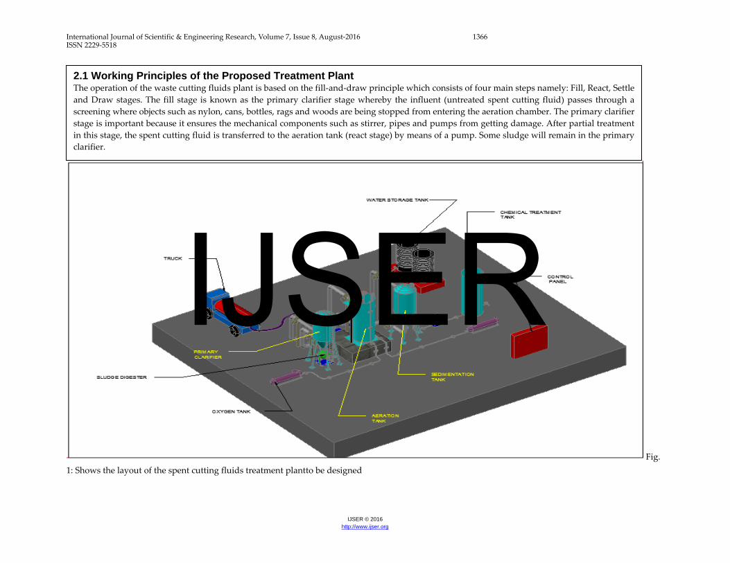
Fig. 1: Shows the layout of the spent cutting fluids treatment plantto be designed
2.1 Working Principles of the Proposed Treatment Plant The operation of the waste cutting fluids plant is based on the fill-and-draw principle which consists of four main steps namely: Fill, React, Settle and Draw stages. The fill stage is known as the primary clarifier stage whereby the influent (untreated spent cutting fluid) passes through a screening where objects such as nylon, cans, bottles, rags and woods are being stopped from entering the aeration chamber. The primary clarifier stage is important because it ensures the mechanical components such as stirrer, pipes and pumps from getting damage. After partial treatment in this stage, the spent cutting fluid is transferred to the aeration tank (react stage) by means of a pump. Some sludge will remain in the primary clarifier.
IJSER
International Journal of Scientific & Engineering Research, Volume 7, Issue 8, August-2016 1367 ISSN 2229-5518
IJSER © 2016 http://www.ijser.org
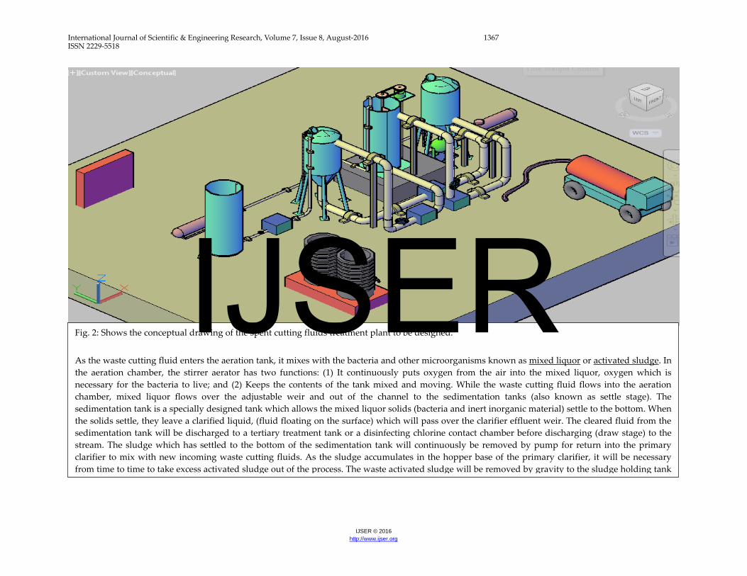
Fig. 2: Shows the conceptual drawing of the spent cutting fluids treatment plant to be designed. As the waste cutting fluid enters the aeration tank, it mixes with the bacteria and other microorganisms known as mixed liquor or activated sludge. In the aeration chamber, the stirrer aerator has two functions: (1) It continuously puts oxygen from the air into the mixed liquor, oxygen which is necessary for the bacteria to live; and (2) Keeps the contents of the tank mixed and moving. While the waste cutting fluid flows into the aeration chamber, mixed liquor flows over the adjustable weir and out of the channel to the sedimentation tanks (also known as settle stage). The sedimentation tank is a specially designed tank which allows the mixed liquor solids (bacteria and inert inorganic material) settle to the bottom. When the solids settle, they leave a clarified liquid, (fluid floating on the surface) which will pass over the clarifier effluent weir. The cleared fluid from the sedimentation tank will be discharged to a tertiary treatment tank or a disinfecting chlorine contact chamber before discharging (draw stage) to the stream. The sludge which has settled to the bottom of the sedimentation tank will continuously be removed by pump for return into the primary clarifier to mix with new incoming waste cutting fluids. As the sludge accumulates in the hopper base of the primary clarifier, it will be necessary from time to time to take excess activated sludge out of the process. The waste activated sludge will be removed by gravity to the sludge holding tank
IJSER

International Journal of Scientific & Engineering Research, Volume 7, Issue 8, August-2016 1368 ISSN 2229-5518
IJSER © 2016 http://www.ijser.org
3 MATERIALS AND METHOD The design was carried out using principles of engineering design with due consideration to cost, ease of operation, serviceability, durability and performance. The design of this treatment plant was separated into three distinct phases which include: (1) Design of machine components (such as tank volume, stirrer, pipes, electric power rating and belts designs), (2) Design of biological kinetics and (3) Design for fluid flow. 4 RESULTS 4.1 Design for Future Expansion of Metalworking Workshops This section includes designing a municipal waste cutting fluids treatment plant for Ibadan city, Nigeria for a projected period of 20years. A recently completed survey to metalworking workshops in Ibadan has showed that there are 103
operating metalworking workshops. By considering future increase of the metalworking workshops, we can determine the possible number of workshops in 20 years as follows: P˕ = P˳ + (K t Pₒ) (1) Where, P = Future number of metalworking workshops P˳ ⇒ Present number of metalworking workshops = 103 t ⇒ Design period required for the plant = 20 years K ⇒ Constant = 0.03 P₂ₒ = 164.8 Therefore, the proposed waste cutting fluids plant will be designed for approximately 165 metalworking workshops for a 20 years design period. The waste treatment plant has been designed based upon the following design for reactor parameters:
TABLE 1
DESIGN PARAMETERS CONSIDERED FOR THE TREATMENT PLANT Design Parameter Range Design Average daily flow of waste cutting fluids (Mg d) - 0.1 Maximum Yield Coefficient (Y), lb VSS/lb BOD5 0.4 – 0.8 0.6 Endogenous Decay Coefficient (kd), day – 1 0.025 – 0.075 0.06 Mixed Liquor Suspended Solids (X), mg/L 1,000 – 6,500 4,500 Volatile Suspended Solids Fraction (Xa) 0.5 – 0.8 0.8 Decay Fraction (fd) 0.78 – 0.82 0.8 Density of mild steel material considered (kg/m3) - 7,850 Acceleration due to gravity, g (m/s) - 9.81 Sludge age in the reactor, θRc (days) 5 – 15 8 Influent substrate, BOD5 concentrate (So) [mg/L] - 240 Effluent substrate (BOD5) concentrate (S) [mg/L] - 10 Concentration of sludge in return line, Xr (mg/L) - 8,000 Concentration of solids in effluent, Xe (mg/L) - 0 Peaking factor - 2.5 Surface loading rate in settling tank (gal/day/ft3) - 400 Input waste sludge, (gal/day) - 3300 Thickened waste activated sludge (%) - 5.0 Minimum liquid temperature for aerobic digestion (oC) - 15 Maximum liquid temperature for aerobic digestion (oC) - 30 Sludge concentration in the digester (%) - 70 Volatile fraction of digester suspended solids - 0.8 Specific gravity of digester sludge - 1.03 Density of water (kg/m3) - 994.6 Sludge cake solids - 0.25 Sludge feed solids - 0.05 Sludge centrate solids - 0.003 Conversion factor from BOD5 to BODL - 0.68 Cake density (lb/ft3) - 60
IJSER

International Journal of Scientific & Engineering Research, Volume 7, Issue 8, August-2016 1369 ISSN 2229-5518
IJSER © 2016 http://www.ijser.org
The reactors have been calculated with several design parameters. The reactors will be provided with stirrer for mixing, oxygen delivery requirements and a digester for dewatering of sludge from the plant. 4.2 Designs for Machine Components 4.2.1 Reactor Tank Design The reactor tank designed is a combination of two shapes: a cylinder with a conical hopper at its base to enable storage of spent cutting fluids. Volume of reactor= [Volume of cylinder +Volume of cone with a tip (frustum)] (2) Where, Volume of cone with a tip (frustum) ⇒ πh
3[(R₁2 + R₁r₁ + r₁²) − (R₂² + R₂r₂ + r₂²)] (3)
Where (R₁2 + R₁r₁ + r₁²) − (R₂² + R₂r₂ + r₂²) is wall thickness of frustum Let h be the height, R the radius of the upper base, and r the radius of the lower base of the frustum. Generally, volume, V, for a hollow cylinder is given by: V = Area x height = π(r₁2 − r²₂)h (4) Thickness of the cylindrical wall, t: t = r₁- r₂ Hence Weight of reactor tank = Volume of reactor tank x Density of steel (5) Volume occupied by steel = Volume of the reactor Density of material = 7850 kg/m3 Mass of reactor tank = volume of reactor tank x Density of material to be considered Weight of reactor tank = Mass of reactor tank x Acceleration due to gravity 4.2.2 Determination of Conical Hopper Outlet Diameter The opening of the diameter for conical hoppers is given by (Jenike, 1964)
D = H(θ)CASρg/gc
(6)
H (θ) = 2 + θ
60 (7)
Where gc is gravity constant conversion factors to convert the result from units of mass to units of force 1kgm
Ns2 . Typical value for H is about 2.4 (Jenike, 1964). Therefore θ semi included angle of the materials from equation (5) is 24°.
Fig 3: Conical Hopper with outlet size D and semi included angle Ɵ As commonly practiced, the coefficient of friction is expressed as the angle of wall friction given by ∅ as; ∅ = arc tan(µ) (8) With known values of semi included angleƟ, wall friction ∅ and the effective angle of internal friction, the flow factor (ff) can be determined from the Jenike published charts for conical hopers.
For flow: σcff
> 𝜎𝜎𝜎𝜎 (9)
Assuming σy and σc are related by the material flow function σy = σc1.34 Thus, the criterion for flow becomes [σy1/1.34
ff] >σy
And so the critical value of unconfined yield stress σRcrit is found when [σy1/1.34
ff ] = σy(10)
ff = 1.54From the Jenike published chart for conical hoppers. The angle θ was reduced by 3° as a margin of safety (1964). Therefore θ used was 21° throughout. Hence solving for σy from equation (1) gives σRcrit By applying law of indices we have, σy(-0.34/1.34)= 1.54 Therefore σyR equals to σcritR is 0.1823 kN/m2
D =2.4 x 0.1823 x 1000
900 x 9.81
Minimum diameter of circular outlet D is 0.0495 4.2.3 Determination of Mass Flow Rate of Conical Hopper The mass flow rate or discharge rate of a conical hopper was determined by the equation (Jenike, 1964): ṁ=ρ°A√ Dg
2(m+1)Tan θ (11)
Where A = πD²4
(12) For conical hopper m = 1 The stress action on the hopper wall is given by:
IJSER

International Journal of Scientific & Engineering Research, Volume 7, Issue 8, August-2016 1370 ISSN 2229-5518
IJSER © 2016 http://www.ijser.org
Pv = ρ°gB
4µKgc �1 − exp �−
4zµKD
�� (13)
Where B is the hopper maximum diameter and z is the cylinder height To estimate the normal stress on the hopper wall Jassen’s assumption was applied Pw = KPv (14) The material that can withstand the maximum stress acting on the wall of the hoppers should be selected. Capacity Design for a Given Electric Motor Rating The design for motor output power enables appropriate selection of a motor with enough power to start and run the machine at full load. Power = F x V (15) Where P = Power in watts F = Rotational force acting on the shaft in Newton (N) V = Linear velocity of the shaft in meters/seconds But F = ma (16) M = Mass of rotating shaft in kilogram (kg) a = Angular acceleration of the motor in radian/seconds square (rad/s2) a = w²r (17) w = angular velocity of the motor in radian/seconds w = v/r Therefore v = wr (18) By putting equation (17) into (16) F = mw2r (19) By putting (18) and (19) into (20)
But w = 2πN60
(21) Putting (21) into (20)
P = 8M �πN60�
3
r2(22)
4.2.4 Calculation of the Mass of Rotating Stirrer D =
MV
(23)
Where D = Density of stirrer in kg/mm3 M = mass of stirrer in kg V = volume of stirrer in mm3 But V = lbh (24) L = length of stirrer in mm For horizontal component of the stirrer
Vhc = volume of horizontal component of the stirrer Vhc = 4 (lbh)(25) For the vertical component of the stirrer Vvc = Volume of vertical component of the stirrer Vhc = 4 (lbh)(26) By adding the horizontal and vertical components, we obtain the volume of the stirrer. Density of stirrer is material dependent. For example, density of mild steel is 7.85 x 10⁶kg/mm3
Mass = density x volume (27) The mass to be obtained from equation (27) will be substituted into equation (22) to get the electric power rating
P = 8M �πN60�
3
r2
P = electric motor power rating M = mass of rotating stirrer N = speed of the motor r = radius of themotor pulley 4.2.5 Belt Selection and Design There is need to select a belt that will surely transmit the ron as required under a reasonable tension without failure (cutting). Also the belt and the pulley must also be designed to allow the two to work together in harmony (to match each other and to hold firmly to each other). The speed of the driving pulley and the driven pulley can be expressed as DeNe = DsNs (28) De = Driving pulley diameters (mm) Ne = Speed of driving pulley (rpm) Ds = Driven pulley diameter (mm) Ns = Speed of driven pulley (rpm) The driving pulley can be determined from the electric motor to be considered. For instance, if the speed and diameter of the driving pulley are 600 rpm and 50 mm respectively, then to express the diameter of the driven pulley by considering speed input ratio 1:5, we transform equation (28).
Ds = DeNe
Ns
4.2.6 Center to Center Distance Design The minimum distance between driving and driven pulleys for appropriate belt tension is obtained below
C = 1 2
(D₁ + D₂) + D₂ (29)
IJSER
International Journal of Scientific & Engineering Research, Volume 7, Issue 8, August-2016 1371 ISSN 2229-5518
IJSER © 2016 http://www.ijser.org
C = the minimum distance between the pulleys in meters D1 = Pitch diameter of the driving pulley (motor pulley) in meters. D2 = Pitch diameter of the driven pulley 4.2.7 Design for Belt Length The design generally specifies the type of standard belt to be selected. Design length for belt is obtained from
L = 2C + π 2
(D₂ + D₂) + (D₂ − D₁)²
4C (30)
L = Belt length C = Minimum distance between the pulleys D1 = Pitch diameter of the driving pulley (motor pulley) in meters D2 = Pitch diameter of the driven pulley 4.2.8 Tension in the Belt The tension T1 acting on the tight side of the belt and the tension T2 acting on the slack side of the belt are calculated using the equation at Hall et al (1982). T₁ − mV²T₂ − mV²
= ℯ fα
sin 0.5θ (31)
Where m = mass of a unit length of the belt (kg) V = linear velocity of belt (m/sec) ∝ = angle of wrap on pulley (rad) f = coefficient of friction between belt & pulley. T1 = Tension in the tight side of belt (N) T2 = Tension in the slack side of (N) θ = Groove angle for v – belt (degree). The maximum tension in the tight side of the belt depends on the allowable stress of the material. Linear velocity V is given by
V = π x Ds x Ns
60 (32)
The angle of wrap between on the small and large pulleys for open belt is determined using Hall et al (1982).
α1 = 180° − 2sin−1 ⦋R − r
C⦌ (33)
α2 = 180° + 2sin−1 ⦋R − r
C⦌ (34)
α₁ = angle of wrap on small pulley α₂ = angle of wrap on large pulley R = radius of large pulley (m) r = radius of small pulley (m) C = center distance of shaft (m)
4.2.9 Pipe Design Cross – sectional inside area of a pipe can be calculated as
A = π�di2�
2
= π �di2
4 � (35)
Where A = cross sectional inside area of pipe (mm2) di = inside diameter of the pipe (mm2) Similarly, the cross – sectional outside area of the pipe can be calculated as
A = π�do2�
2
= π �do2
4 � (36)
Where do = outside diameter (m) Therefore, the cross-sectional wall area – or area of piping material can be calculated as
Am = π �do2�
2
− π �di2�
2
= π �do2 − di2
4 � (37)
Where Am = cross – sectional wall area of pipe (mm2) 4.2.0 Shaft Design To determine the diameter of the shaft by neglecting bending moment we have:
T = 60P
2πN(38)
Where T = Torque transmitted by shaft P = Power transmitted by the electric motor N = Number of revolution of shaft per minute Torque transmitted by the shaft can also be calculated in terms of the diameter of the shaft as:
T = π x τ x d³
16 (39)
Where τ = Allowable shear stress of the material d = diameter of the shaft The value of torque obtained in equation (38) can be substituted into (39) 4.3 Designs for Biological Kinetics
IJSER

International Journal of Scientific & Engineering Research, Volume 7, Issue 8, August-2016 1372 ISSN 2229-5518
IJSER © 2016 http://www.ijser.org
4.3.1 Volume of the Reactor The volume of the reactor can be determined using the following equation derived from Monod kinetics:
Vr = θcQY (So − S)Xa (1 + Kdθc)
(40)
Where Vr = Reactor volume (M gal) (m3) θc = the average time that the sludge remains in the reactor (sludge age). θc ranges from 5 to 15days for a complete mix activated sludge process. The design of the reactor is based on θc on the assumption that substantially all the substrate (BOD) conversion occurs in the reactor.. A θc of 8 days will be assumed. Q = Average daily influent flow rate (Mgd) = 0.1 Mgd. Y = Maximum yield coefficient (mg VSS/mg BOD5). For the activated sludge process for municipal treatment plant Y ranges from 0.4 to 0.8. A Y of 0.6mg VSS/mg BOD5 will be assumed. Essentially, Y represents the maximum mg of cells produced per mg organic matter removed. Sₒ = Influent substrate (BOD5) concentration (mg/L) = 240 mg/L S = Effluent substrate (BOD5) concentration (mg/L) = 10mg/L Xa = Concentration of microorganisms in reactor Mixed Liquor Volatile Suspended solids (MLVSS) in mgL. It is generally accepted that the ratio MLVSS/MLSS is 0.8, where MLSS is the Mixed Liquor Suspended Solids concentration in the reactor. MLSS represents the sum of volatile suspended solids (organics) and fixed suspended solids (inorganics). For a complete mix activated sludge process, MLSS ranges from 1,000 to 6,500 mg/L. An MLSS of 4,500 mg/L will be assumed. Kd = Endogenous decay coefficient (d-1) which is a coefficient representing the decrease of cell mass in the MLVSS. For the activated sludge process for municipal wastewater Kd ranges from 0.025 to 0.075 d – 1 . A value of 0.06d – 1 will be assumed. Therefore: Vr = 0.021 M gal 4.3.2 Determination of the Hydraulic Retention Time The hydraulic retention time (θ) is given by:
θ =VrQ
(41)
Where
θ = hydraulic retention time Vr = Volume of reactor Q = Influent flow rate θ = 0.21 M gal 4.3.3 Determination of the Quantity of Sludge Wasted The observed cell yield 𝑌𝑌𝑌𝑌𝑌𝑌𝑌𝑌 = Y
1+Kdθc (42)
Where, Yobs = Observed cell yield Yobs= 0.41 mg/mg Hence, 0.41 mg/mg represents the actual cell yield that would be observed. The observed cell yield is always less than the maximum cell yield (Y). the increase of MLVSS is calculated using the equation below: Px = Yobs Q (S˳ − S)(8.34 lb/Mgal/ mg/L) (43) Px is the quantity of the wasted sludge Px = 78.65 lb/VSS/d Therefore the increase in the mass of mixed liquor suspended solids (MLSS) = Px(ss) = Px
Xa (44)
Px(ss) = 98.31 lb SS/d. This is the total mass of sludge wasted from the system each day 4.3.4 Determination of Oxygen Requirement based on Ultimate Carbonaceous Oxygen Demand (BODL) The theoretical oxygen requirements are determined using the BOD5 of the wastewater and the amount of organisms (Px) wasted from the system each day. If all BOD5 were converted to end products, the total oxygen demand would be computed by converting BOD5 to ultimate BOD (BODL), using the appropriate conversion factor. Therefore the theoretical oxygen requirements for the removal of the carbonaceous organic matter in wastewater for an activated sludged system can be determined by the equation below: LbO2/d = �total mass of BODʟ utilized, lb
d� −
1.42 �mass of organisms wasted, lbd� (45)
For converting BOD5 to BODL, a conversion factor, f is introduced. The most commonly used value of f is 0.68. Therefore, the theoretical oxygen required for the removal of the influent BOD5 is calculated thus:
IJSER
International Journal of Scientific & Engineering Research, Volume 7, Issue 8, August-2016 1373 ISSN 2229-5518
IJSER © 2016 http://www.ijser.org
lb O₂/d = Q (S˳−S)(8.34) (lb /Mgal )/(mg /L))f
- (1.42)(Px) (46) lb O₂/d = 270.9 lb O₂ /d It is recommended that the aeration equipment be designed with a safety factor of at least 2. Therefore, in sizing aeration equipment a value of (2) (270.9 lb O2/d) = 541.9 lb O2/d is to be used. 4.3.5 To Compute the Waste Activated Sludge (WAS) and Return Activated Sludge (RAS) Requirement Control of activated sludge process is important to maintain high levels of treatment performance under a wide range of operating conditions. The principle factors used in process control are (a) maintaining dissolve oxygen levels in the aeration tanks, (2) regulating the amount of return activated sludge (RAS), and (3) controlling the waste activated sludge (WAS). One of the methods of calculating the waste sludge flow rate is as shown below. X = Mixed Liquor Suspended Solids (MLSS) = 4500 as earlier stated Q = Return activated sludge pumping rate (Mgd) Xr = Concentration of sludge in the return line�mg
L�.
When lacking site specific operational data a value commonly assumed is 8000 mg/L Qe = Effluent flow are (Mgd) Xe = Concentration of solids in effluent�mg
L�. When
lacking sites specific operational data, this value is commonly assumed to be zero. Qw = Waste activated sludge (WAS) pumping rate from the return line (Mgd). Therefore, the wasting rate is calculated using the following:
θc = VrX
Qw′Xr + QeXe (47)
Assuming the concentration of solids in the effluent from the settling tank is low, then the above equation reduces to:
θc =VrXQw′Xr
⇒ Qw′ = VrXθcXr
(48)
Qw′ = 0.0015 Mgd To determine the waste activated sludge (WAS) using this method, the solids concentration in both the aeration tanks and the return line must be known. Assuming that the sludge blanket level in the settling tank remains constant and that the solids in the effluent from the settling tank (Xe) are
negligible, a mass balance around the settling tank yields the following equation for RAS pumping rate:
Qr =XQ− XrQw′
Xr − X (49)
Using values defined previously, the RAS pumping rate is computed to beQr = 0.125 Mgd The ratio of RAS pumping rate to influent flow rate, or recirculation ratio (α), may now be calculated:
α = Qr Q
= 1.25 ⇒ OK (50)
Recirculation ratio can vary from 0.25 to 1.50 depending upon the type of activated sludge system used. 4.3.6 To Calculate the Growth of Biological Sludge The growth of biological sludge over time period, ∆t, mg/L is given by: ∆x∆t
= XVrθc
(51)
Growth of biological growth is 11.81 kg/day 4.3.7 To Design the Circular Settling Tank Municipal waste cutting fluids with an average daily flow of 0.1 Mgd exists the aeration tanks of a standard activated sludge treatment process. Design of circular settling tank to separate the sludge from the effluent is to be designed. The settling tank will work in conjunction with the aeration tank. Assume a peaking factor of 2.5. The following are of paramount importance in the design of circular settling tank: (1) Determination of the peak flow (2) Determination of the settling tank surface area using surface loading criteria (3) Determination of the settling tank surface area using solids loading criteria (4) Determination of the number of settling tanks. 4.3.8 To Calculate the Peak Flow Using a peaking factor of 2.5. The daily peak flow Qp is given by: Qp = Peak flow x Average daily flow = 0.25 Mgd (52) 4.3.9 To Calculate the Settling Tank Surface Area Using Surface Loading Criteria The recommended surface loading rates vary depending upon the type of activated sludge
IJSER

International Journal of Scientific & Engineering Research, Volume 7, Issue 8, August-2016 1374 ISSN 2229-5518
IJSER © 2016 http://www.ijser.org
process used. However, surface loading rates ranging from 200 to 800 gal/day/ft2(8.09 to 32.4 L/m². d) for average flow, and a maximum of 1,000 gal/day/ft² (40.7 L/m². d) for peak flow are accepted design values. For a Qp of 0.25 Mgd �250,000 gal
day� and a design surface
loading rate of 400 gal/ day /ft2 at peak flow the surface area (A) of a settling tank may be calculated: Surface loading rate (gal/day/ft²)
= Settling tank effluent flow (gal/day)
Settling tank area (m2) (53)
Therefore, A = 625ft2 4.3.0 To Calculate the Settling Tank Surface Area Using Solids Loading Criteria The total solids load on a clarifier consists of contribution from both the influent and the return activated sludge (RAS). Qr = RAS flow rate = 1.25 (Q) = 0.125 Mgd (54) X = MLSS in aeration tank = 4500 mg/L Therefore, the maximum solids loading occurs at peak flow and maximum RAS flow rate. The maximum solids entering the clarifier are calculated using: Maximum solids (lb/d) = (Qp +Qr)(X)(8.34 lb. mg. Mgal) (55) Using values given above; Maximum solids = 14,073.75 lb/d = 586.41 lb/h = of suspended solids Therefore, using a solids loading rate of 2.0 lb/ft2 at peak flow, the surface area of a settling tank may be calculated:
A = Maximum solids
Solids loading rate = 293.2ft² (56)
In this case, the solids loading dominate and dictate the required settling tank area. 4.4 Design of an Aerobic Digester An aerobic digester is to be designed to treat the waste sludge produced by an activated sludge waste water treatment plant. The input waste sludge will be 3,300gal/d �5 d
wk. only� of thickened
waste activated sludge at 5.0 percent solids. The following assumptions will be considered:
(i) The minimum liquid temperature is 15oC and the maximum liquid temperature is 30oC.
(ii) The system must achieve a 35 percent volatile suspended solids (VSS) reduction
(iii) Sludge concentration in the digester is 70 percent of the incoming thickened sludge concentration.
(iv) The volatile fraction of digester suspended solids is 0.8.
Factors to be considered in designing aerobic digester include temperature, solids reduction, tank volume (hydraulic retention time), oxygen requirements and energy requirements for mixing. The total mass of solids processed by the digester will be 98.31 lb SS/d which is the total mass of solids wasted from the treatment facility. The total mass of VSS input to the digester is: (0.8) Px(ss) = 78.65 lb/d (57) VSS reduction = (0.35) (Total mass of VSS input to digester) = 27.53 lb VSS reduced/day (58) Digested sludge leaving the digester = (Px(ss) – VSS reduction) lb/d = 70.78 lb/d (59) 4.4.1 To Calculate the Daily Volume of Sludge for Disposal The volume of sludge to be disposed daily (Qi) is:
Qi = (3,300gal/day) �57� = 2357gal/day (60)
4.4.2 To Calculate the Volume of Digested Sludge The volume of digested sludge is:
V = Ws
(ρ)(s. g)(% solids) (61)
Where V = sludge volume (ft3) (m3) Ws = weight of sludge (70.78)(lb( (kg) ρ = density of water (62.4lb/ft3) s.g. = specific gravity of digested sludge (assume s.g. = 1.03) % solids = percent solids expressed as a decimal (incoming sludge: 5.0%) Therefore, the volume of the digested sludge is: V = 22.03ft3/d 4.4.3To Calculate the Volume of the Aerobic Digester Volume
IJSER

International Journal of Scientific & Engineering Research, Volume 7, Issue 8, August-2016 1375 ISSN 2229-5518
IJSER © 2016 http://www.ijser.org
The volume of the aerobic digester is calculated using the equation below, assuming the digester is loaded with waste activated sludge only.
V = QiXi
X (KdPv + 1/θc) (62)
Where V = Volume of aerobic digester, ft2/d (m3/d) Qi = Influent average flow rate to the digester, ft3/d (m3/d) Xi = Influent suspended solids, mg/L Kd = Reaction rate constant d-1, This may range from 0.05 d–1 at 15oC to 0.14d–1 at 25oC (assume 0.08 d–1 at 15oC) Pv = Volatile fraction of digester suspended solids (expressed as a decimal) = 0.8 (80%) as stated in the initial assumptions. Θc = Solids retention time (sludge age), d assuming 20.8 d V = 30.041 ft3 4.4.4 To Determine the Sludge Feed Rate Required Assuming the designed digester will be used to produce 1200 gal/d of aerobically digested sludge 5 h/d, 3 d/wk, then the sludge fed rate is: Sludge feed rate
= Quantity of anerobic digested sludge
Operating time of facility daily (63)
Therefore, sludge feed rate = 1200 gal /day [(5 h/d) (60 min /h)
= 4.0 gal/min By considering a feed sludge specific gravity of 1.03, the sludge feed in lb/h is calculated using the equation below: Ws
= (V)(ρ)(s. g)(% solids)(60 min/hr )
7.48 gal/ft³ (64)
Where Ws = Weight flow rate of sludge feed, lb/h �kg
h�
V = Volume flow rate of sludge feed, gal/min (L/s) s.g. = Specific gravity of sludge % solids = Percent solids expressed as a decimal ρ = density of water (62.4lb/ft3) By using the values obtained above, the sludge feed in lb/h is: Ws = 103.1 lb/hof dry solids 4.4.5 To Compute the Solids Capture
A recovery formula is used to determine the solids capture, the equation for percentage solids recovery is given by:
R = 100 �CsF� �
F − CcCs − Cc
� (65)
Where R = Recovery, percent solids Cs = Cake solids, percent solids (assuming 25%) F = Feed solids, percent solids (assuming 5%) Cc = Cenztrate solids, percent solids (assuming 0.3%) Therefore, R = 95.14% 4.4.6 To Calculate the Dewatered Sludge Cake Discharged Rate The dewatered sludge (cake) discharge rate is calculated using the following: Cake discharge rate (lb/h) dry solids = (sludge federate, lb/h) (solids recovery) (66) Cake discharge rate = 98.09 lb/h dry cake The wet cake discharge in (lb/h) is calculated using the following: Wet cake discharge (lb/h)
= Cake discharge rate, lb/h
Cake % solids (67)
Therefore, wet cake discharge = 392.lb/h wet cake The volume of wet cake assuming a cake density of 60lb/ft3us calculated as follows: Volume of wet cake (ft³/h)
= Wet cake rate, lb/hCake density, lb/ft³
(68)
= 6.54 ft³/h wet cake For a dewatering facility operation of 5 hr/day, the volume of dewatered sludge cake to be disposed of per day is: (6.54 ft³/h)(5 hour/day) = 32.7 ft³/d
= 244.7 gal/day 4.4.7 To Determine the Percent Reduction in Sludge Volume The percentage reduction is sludge volume is then calculated using the following: % Volume Reduction
= Sludge volume in − Sludge volume out
Sludge volume in x 100% (69)
=1200 gal/day− 244.7 gal/day
1200 gal/day x 100%
% Volume Reduction = 79.61% 4.4.8 To Determine the Flow rate required for Sludge Pump
IJSER
International Journal of Scientific & Engineering Research, Volume 7, Issue 8, August-2016 1376 ISSN 2229-5518
IJSER © 2016 http://www.ijser.org
The required flow rate for the sludge pump using 4 h.d, 7d/wk operation scheme is:
Flow rate (gal/min) = 1200gal/day
(5 h/d)(60 min/hr)= 4 gal/ min (70)
The velocity of 4.0 gal/min in a 3 inch (76.3mm) diameter pipe is: Velocity
= 4.0 gal/min
(7.48gal/ft) �π4� (3 inch 12 inch/ft⁄ )²(60s/min)
= 0.18ft/s (71) 4.5 Designs for Fluid Flow 4.5.1 Detention Time The theoretical (calculated) time required for a given amount of waste fluid to pass through a tank at a given rate of flow. The time required to fill a tank at a given flow. The detention time in hours can be calculated with the formula below: Detention Time
=(Clarifier volume, gal)(24 hr/day)
Flow, gal/day (72)
Volume = 0.785 x Diameter of clarifier x Diameter of clarifier x Depth x 7.48 gal/ft3 (73) 4.5.2 Flow Rate of Waste Cutting Fluid Travelling through a Pipe Flow rate, Q = Velocity x Transverse internal area of pipe A (74) Where Velocity = rate of wastewater travelling through a pipe Transverse internal area = 0.785dᵢ² (75) 5.0 Conclusion The design of a spent cutting fluids treatment plant was carried out for Ibadan community, Nigeria. Plant capacity of 0.1Mgd was designed using engineering principles.The designed treatment plant contained the major components such as reactors, mixers, aeration gas, and a digester (to dewater moisture content of sludge). 6.0 References Fatima, H.A, Salah, F (2011). Design of Wastewater Treatment Plant.Republic of Iraq Ministry of Higher Education and Scientific Research. A B.Sc.
Project submitted to to the Building & Construction Department of the University of Technology. Vigneswaran, S., Sundaravedivel, M and Chaudhary, Sequencing Batch Reactors: Principles, Design/Operations and Case Studies D.S. Water and Wastewater Treatment Technologies.. Jenike A.W (1964), Storage and Flow of Solids, Bulletin No. 123, Utah Engineering Experiment Station, University of Utah, Salt Lake City, USA (Revised edition 1970) Khurmi R.S., Gupta J.K., A textbook of machine design. Paperback: 1230 pages Publisher. Fadare, D.A (2004). Development of an Organo-mineral fertilizer processing plant.A Ph.D thesis, Mechanical Engineering Department, University of Ibadan, Ibadan, Nigeria. Bamiro O.A and Osibanjo O (2004).Pilot study of used oil in Nigeria.Conducted by Basel convention regional coordinating center in Nigeria in collaboration with secretariat of Basel convention, Geneva. Vesna, B.L, Ivan, M. K, Miodrag, L.L, Dragiša, S. S, Dejan, U.S, Vlada, B.V. Scaling up the chemical treatment of spent oil-in-water emulsions from a non-ferrous metal-processing plant.SCIENTIFIC PAPER Hem.Ind. 67 (1) 59–68 (2013). Kilgore, M (1999), Litter and Pollution – Chintimini Wildlife Rehabilitation Center. http: www.chintiminiwildlife.org/education Kazeem, R.A., Fadare, D.A., Ogundiran, M.B. (2015). An Assessment of Metalworking Fluids Utilization and Management Practices of Machining Workshops in Ibadan. Tyler G, Hicks, P.E (2006). Handbook of Mechanical Engineering Calculations.Second Edition. Sulaymon, A.H, Thuaban, L.H (2010), Demulsification of Cutting Fluid before Disposal tothe Environment. Journal of Engineering, 16(1), 4580- 4592 Janssen, H.A (1985), Versucheüber, G, Verein, D, Zeitschrift, Pages 1045-1049 Jenike, A.W., Storage and Flow of Solids, Bulletin 123, University of Utah Engineering Station, 1964 (revised, 1976).
IJSER

International Journal of Scientific & Engineering Research, Volume 7, Issue 8, August-2016 1377 ISSN 2229-5518
IJSER © 2016 http://www.ijser.org
ADDITIONAL DETAILS OF THE DESIGNED SPENT CUTTING FLUIDS TREATMENT PLANT
Fig.4. Showing the third angle projection of the designed spent cutting fluids treatment plant.
IJSER