manual_Oscilloscope_DSO203 y circuito electronico.pdf
29
www.elechouse.com 1 Mini DS203 OSC Manual Copyright reserved by elechouse
-
Upload
pablo190381 -
Category
Documents
-
view
61 -
download
1
Transcript of manual_Oscilloscope_DSO203 y circuito electronico.pdf

www.elechouse.com
1
MiniDS203OSCManualCopyrightreservedbyelechouse

www.elechouse.com
2
Intro
DS203 V2.6 is a pocket size 4 channel digital Oscilloscope for common electronic engineering tasks. It's based
on ARM cortex M3 (STM32F103VCT6) 32 bits platform, providing 72MS/s sampling rate with integrated
FPGA and high speed ADC. Internal 2MB USB disk could be used to store waveform, user application and
upgrade firmware. Due to the palm size and handy performance, it fits in-field diagnosis, quick measurement,
hobbyist projects and wherever convenience matters. Scheme and source files are also open for re-innovating.
Features
Portable and lightweight
Color display
Waveform storage and playback
Two 72MS/s analog channels, plus two digital channels
Firmware upgradable
4 programmable space for user application program
Open Source
Specification
Display Full Color 3" TFT LCD 400 X 240
Input channel Analog: CH(A)\CH(B)
Digital: CH(C)\CH(D)
Max sample rate 72MS/s, 8bit
Sample memory depth 4096 Points for each channel
Vertical Scale 20mV10V/div(xl probe)
Vertical resolution 8 bit
Horizontal sensitivity 0.1uS/Div ~ lS/Div
Horizontal position Adjustable
Input coupling AC/DC
Input impedance >800K
Max input voltage 80Vpp(xl probe)
Trigger type Auto, Normal, Single, SCAN, None
Trigger source CH1/CH2/EXT
Signal generator Sine/Triangle/Saw/Square,lOHz20K Hz

www.elechouse.com
3
Storage Internal 2MB USB disk, BM P, DAT file
Auto measure Max, Min, Vbt, FPS, Vpp, Vdc, RMS
Sampling mode Real time
Dimension 98 * 60 * 14.5 (mm)
Weight 80g (without battery)
Accessories within Pack 2 mcx oscilloscope probe/battery
Basic Operation
Install the battery

www.elechouse.com
4
1. Push the back cover toward the Mini USB port direction.
2. Lift the back cover
3. Install the battery
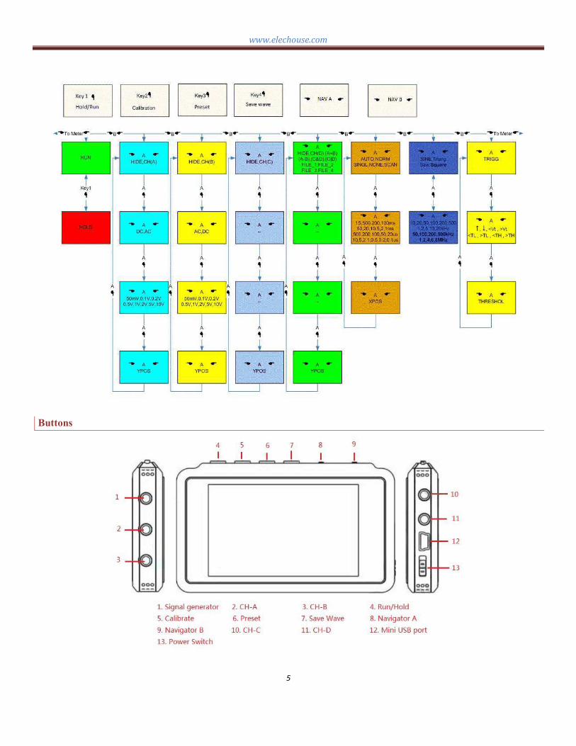
Operation Overview
www.elechouse.com
5
Buttons

www.elechouse.com
6
There are 2 navigators and 4 buttons on DS203
Navigator A
The Navigator A is used to select/change the submenu of menu. Action "Press" Navigate in the sub-menus,
While Action "Pull/ Push" changes the setting of a sub-menu (ref. menu).
For example, when selecting the menu: CHA Control, with Navigator B (ref. Navigator B), Action "Pull/ Push"
of Navigator A changes the setting of sub-menu1, from "CH (A)"to "HIDE". While action "Press" changes
selected sub-menu, making the blink area jump to next item: DC (or AC), Still, Action "Pull/ Push" changes the
setting of this sub-menu.
Action "Press" of Navigator A changes the submenu of CHA Control menu as follows:
Show mode (CH (A)/HIDE) -> Couple mode (AC/DC-) -> Vol sensitivity (50mV-l0V) -> YPOS Select mode.
Navigator B
Navigator B is used to navigate in the main menu (ref. table l), Action "Press" of Navigator B changes menus
from menu Group1 to Group2 (ref. menu) and vice versa; While action Pull/Push" changes the main menu
within a Group.
Run/Hold
The Run/Hold is used to control working state of DS203: Working or Pause
Calibrate
A standard voltmeter and an adjustable voltage source is needed for calibrating the Quad.
In working state, when the menu CHA Control or CHB Control is selected, pressing the Calibrate button
making the Quad enter the calibration status:
1. Connect the standard voltmeter and DS203 in parallel. Input the voltage from the adjustable voltage
source to both voltmeter and DS203.
2. There will some prompt in the first column, eg. "Please connect CH_A input to GND". Input voltage to
DS203 as the prompt. Adjust the value to make it the same as the standard voltmeter, with Navigator A.
And select different range and calibrate item with action "Press" and "Pull/Push" of Navigator B.

www.elechouse.com
7
3. When cursor is at the bottom, select the exit mode with Navigator A, and press the calibrate button to
exit the calibration status.
More calibration information will be supplied in latter pages.
Preset
This button is used to save your setting when using the DS203. With this function, you don't need to configure
your DS203 every time you power it. For example, configure the signal generator as Square, 10kHz, and then
press the Preset Button. You would find the signal generator the same as your last configuration.
Save Wave
Connect DS203 to PC via USB cable. Switch on the device, and then you will find it in your PC.
In order to save the wave in DS203, Template of .bmp files or .dat files must be stored into DS203 first. You can
download the template:
http://www.elechouse.com /elechouse/images/product/DS203/save_wave_tem.rar
www.elechouse.com
8
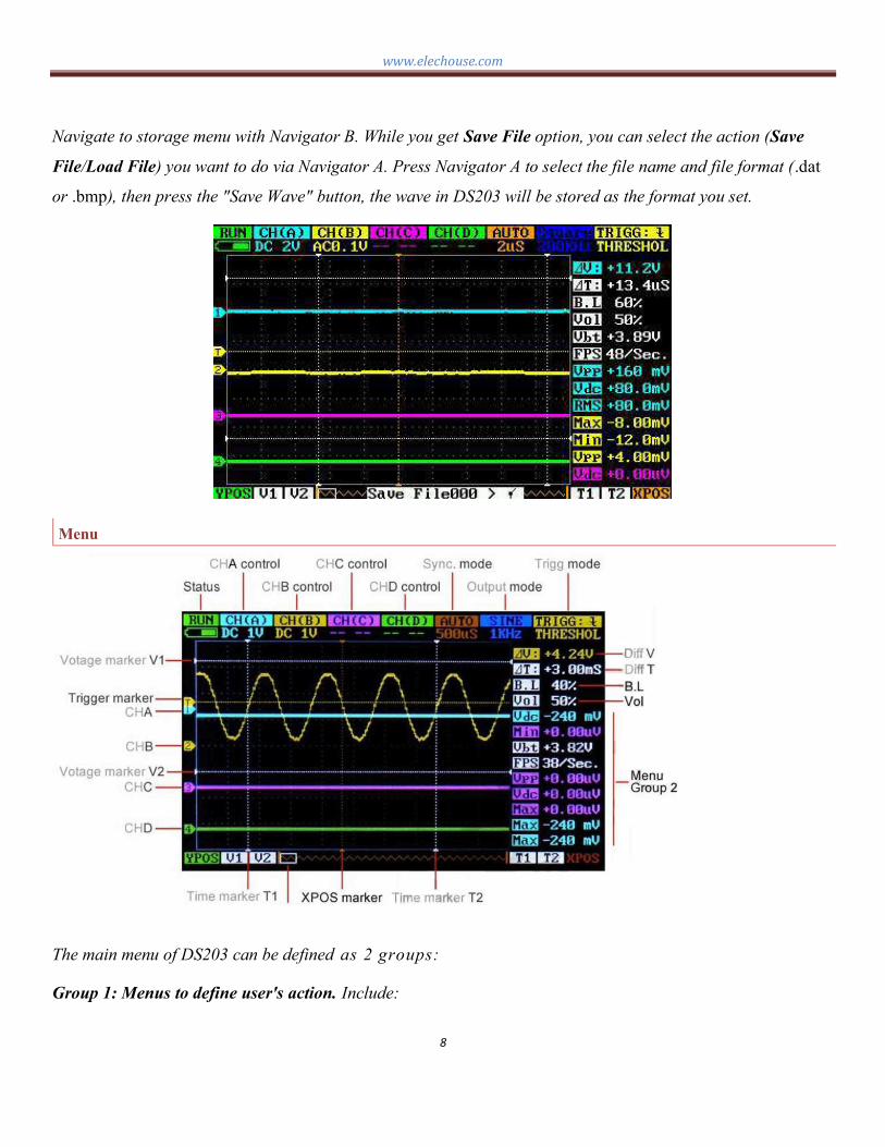
Navigate to storage menu with Navigator B. While you get Save File option, you can select the action (Save
File/Load File) you want to do via Navigator A. Press Navigator A to select the file name and file format (.dat
or .bmp), then press the "Save Wave" button, the wave in DS203 will be stored as the format you set.
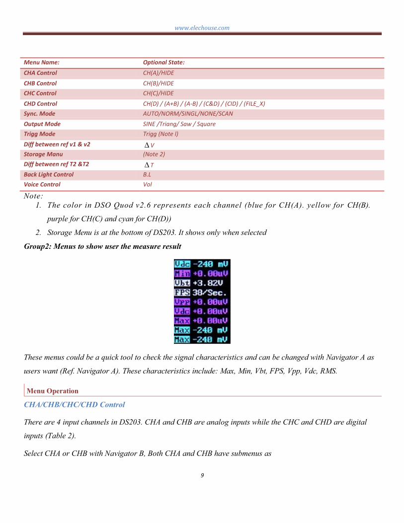
Menu
The main menu of DS203 can be defined as 2 groups:
Group 1: Menus to define user's action. Include:
www.elechouse.com
9
Menu Name: Optional State:
CHA Control CH(A)/HIDE
CHB Control CH(B)/HIDE
CHC Control CH(C)/HIDE
CHD Control CH(D) / (A+B) / (AB) / (C&D) / (CID) / (FILE_X)
Sync. Mode AUTO/NORM/SINGL/NONE/SCAN
Output Mode SINE /Triang/ Saw / Square
Trigg Mode Trigg (Note l)
Diff between ref v1 & v2 V
Storage Manu (Note 2)
Diff between ref T2 &T2 T
Back Light Control B.L
Voice Control Vol
Note:
1. The color in DSO Quod v2.6 represents each channel (blue for CH(A). yellow for CH(B).
purple for CH(C) and cyan for CH(D))
2. Storage Menu is at the bottom of DS203. It shows only when selected
Group2: Menus to show user the measure result
These menus could be a quick tool to check the signal characteristics and can be changed with Navigator A as
users want (Ref. Navigator A). These characteristics include: Max, Min, Vbt, FPS, Vpp, Vdc, RMS.
Menu Operation
CHA/CHB/CHC/CHD Control
There are 4 input channels in DS203. CHA and CHB are analog inputs while the CHC and CHD are digital
inputs (Table 2).
Select CHA or CHB with Navigator B, Both CHA and CHB have submenus as

www.elechouse.com
10
Submenu Function
Show mode Show or hide related input channel
Couple mode AC couple or DC couple
Vol sensitivity Vol sensitivity adjust(50mVl0V)
YPOS adjust mode YPOS adjust
Navigate the submenus with action "press" of Navigator A, and adjust the setting with action "Pull/Push".
Digital input channel CHC is a digital input channel, it only has two submenus: Show mode and YPOS adjust
Mode.Digital
Digital input channel CHD has something different. It can be set to math inputs (Table2). It has sub-menus as
Submenu Function
Show mode HIDE / CH(D) / (A+B) / (AB) / (C&D) / (C|D) /
( FILE_X)
YPOS adjust mode YPos adjust
The results of A+B, A-B, C&D and C|D, can be set as the inputs of channel D. With this function, it is
convenient for the user to observe and analyze the signal of each channel. Besides, the FILE_X can be used as
the input when recalling data from .DAT file (Ref. store and Recall).
Syn . Mo de
AUTO: Always refresh display, synchronize when triggered.
Norm: Display synchronized waveform when triggered, blank if not triggering
Single: Display triggered waveform and hold, blank before triggering.
Scan: Repeatedly sweep waveform from screen left to right.
None: Refresh unsynchronized waveform ignoring triggering.
Mode Trigger Display Synchronization Application
AUTO Yes Always Yes General use
Norm Yes Triggered Yes Periodic signals
SING Yes Triggered Autohold Random pulse
Scan No Always No Monitoring
None No Always No Unsynchronized
www.elechouse.com
11
This menu also has a submenu of Horizontal sensitivity, From O.1s/div t0 1s/div. And a submenu of XPOS,
Each "div" means a grid unit of the screen. You can view the full sampling buffer of a channel with the action
"Push/Pull" of Navigator A.
Output Mode
There are two signal generator sources in the DS203, Digital source and analog source. The
digital source outputs duty ratio is adjustable from 1% to 99% square wave, and frequency from
10HZ to 8MHZ. The analog outputs wave forms include: Sine wave, Triangle wave, Saw wave.
Frequency form 10HZ to 20KHZ.
This menu has a sub-menu as
Submenu Function
Output wave Output wave select
Frequency Set the frequency of output
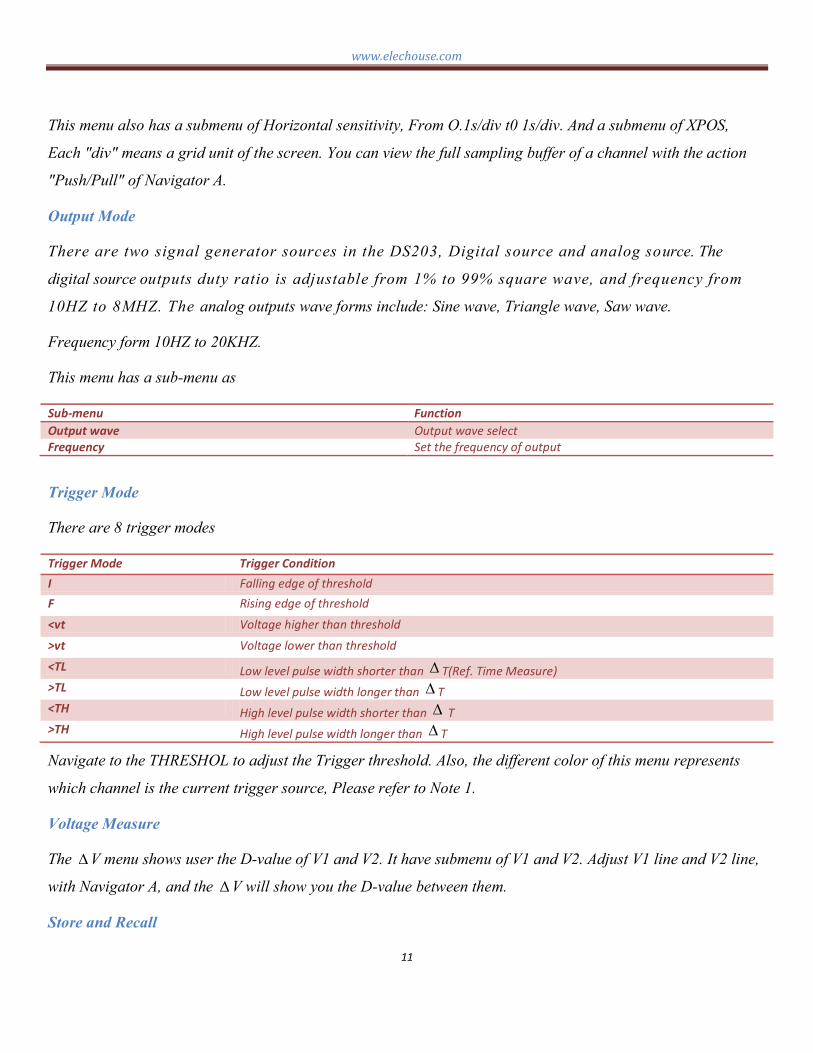
Trigger Mode
There are 8 trigger modes
Trigger Mode Trigger Condition
I Falling edge of threshold
F Rising edge of threshold
<vt Voltage higher than threshold
>vt Voltage lower than threshold
<TL Low level pulse width shorter than T(Ref. Time Measure)
>TL Low level pulse width longer than T
<TH High level pulse width shorter than T
>TH High level pulse width longer than T
Navigate to the THRESHOL to adjust the Trigger threshold. Also, the different color of this menu represents
which channel is the current trigger source, Please refer to Note 1.
Voltage Measure
The V menu shows user the D-value of V1 and V2. It have submenu of V1 and V2. Adjust V1 line and V2 line,
with Navigator A, and the V will show you the D-value between them.
Store and Recall

www.elechouse.com
12
Waveform could be saved to the internal 2MB USB disk, with.bmp or .dat files, and then recalled as the user
want.
Save waveform as .bmp:
1. Copy the Filexxx.BM P to the 2M USB disk, rename the xxx as 000, 001, 002_
2. Navigate to the save menu, select "Save file", "xxx (the one you select to use)" and ".BMP"
3. Push button "Save wave" (The forth button on DS203)
4. Reset the DS203, you will see the saved BMP in your USB disk.
Save and recall .DAT
1. Copy the Filexxx. DAT to the 2M USB disk, rename the
2. Navigate to the save menu, select "Save file", "xxx(the one you select to use)" and ".dat"
3. Press button "Save wave" to store the data into .dat file.
4. In order to recall the data you stored in the USB disk, first navigate to the save menu, select the "load
file""xxx(the one you want to recall)"and ".dat", and then press the button "Save Wave".
5. Navigate to the CHD, select the show mode as File_x(the data in which channel you stored ), and, you
can get the recalled waveform.
Time Measure
The T menu shows user the D-value of T1 and T2. It have submenu of T1 and T2. Adjust T1 line and T2 line,
with Navigator A and the T will show you the D-value between them.
B.L& Vol
B.L (backlight) and Vol can also be adjusted by Navigator A, Reducing the B.L and Vol make benefits to your
battery duration.
Measurement
These menus in menu group 2 are for auto-measurement. There are 9 menus in this group (ref.Figure1. Menu
Group2). Users can set these 9 menus as they need.
There are 7 parameters can be observed for channel A/B/C:
Parameter to measure meaning
Max Max value of input (CHA/B/C)

www.elechouse.com
13
Min Min value of input (CHA/B/C)
Vbt Voltage of battry(common)
FPS Frames per second(common)
Vpp Vpp of input (CHA/B/C)
Vdc Mean value of input(CHA/B/C)
RMS Effective value of input(CHA/B/C)
Also, different color represents different channel. And, because the Vbt and FPS is common for all the channels,
the back color of them is white.
Firmware Upgrade
Firmware can be downloaded via this link: http://www.elechouse.com /elechouse/images/product/DS203/
DS203_firmware.rar
Installation into the DS203 are shown as follows:
1. CFG_FPGA.ADR + VxxxFPGA.bin. The two files for FPGA logic, you need to install the .ADR file and
then the .bin file.
2. logo_00B.ADR + logo_001.bin. The logo files, you need to install the .ADR file and then the .bin file.
3. APP_Bxxx.hex, the app firmware.
4. SYS_Bxxx.hex, the sys firmware.
www.elechouse.com
14
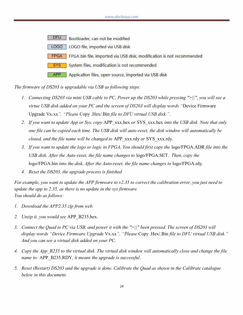
The firmware of DS203 is upgradable via USB as following steps:
1. Connecting DS203 via mini USB cable to PC, Power up the DS203 while pressing ">||", you will see a
virtue USB disk added on your PC and t Device Firmware
Upgrade Vx.xx Copy .Hex/.Bin .
2. If you want to update App or Sys, copy APP_xxx.hex or SYS_xxx.hex into the USB disk. Note that only
one file can be copied each time. The USB disk will auto-reset, the disk window will automatically be
closed, and the file name will be changed to APP_xxx.rdy or SYS_xxx.rdy.
3. If you want to update the logo or logic in FPGA, You should first copy the logo/FPGA.ADR file into the
USB disk. After the Auto-reset, the file name changes to logo/FPGA.SET. Then, copy the
logo/FPGA.bin into the disk, After the Auto-reset, the file name changes to logo/FPGA.rdy.
4. Reset the DS203, the upgrade process is finished
For example, you want to update the APP firmware to v2.35 to correct the calibration error, you just need to
update the app to 2.35, as there is no update in the sys firmware.
You should do as follows:
1. Download the APP2.35 zip from web.
2. Unzip it, you would see APP_B235.hex.
3. Connect the Quad to PC via USB, and power it with the ">||" been pressed. The screen of DS203 will
Vx.xx Copy .Hex/.Bin
And you can see a virtual disk added on your PC.
4. Copy the App_B235 to the virtual disk. The virtual disk window will automatically close and change the file
name to: APP_B235.RDY, it means the upgrade is successful.
5. Reset (Restart) DS203 and the upgrade is done. Calibrate the Quad as shown in the Calibrate catalogue
below in this document.

www.elechouse.com
15
The issue right now in your DS203 can be seen on the screen when you power it on.
Design your own logo
Logo files are included in the firmware package. You can download via the link above.
When you want to change the logo displayed on the screen, you may do it as follows:
1. Design your logo. The logo you designed should be a picture saved as xxx_logo.bmp (note the formate
should be bmp and the name of the logo should be 8 characters including the _ ), and the picture should
be 16 colors and in size of 64x256.The logo picture should be 8.11kB.
2. Then change the document style of the picture (namely the suffix) from .bmp into .bin .
3. Connect the Quad to PC via USB, and power it with the ">||" been pressed. The screen of DS203 will
And you can see a virtual disk added on your PC.
4. Copy the LOGO_00B.ADR that you downloaded into the Virtual disk. It will reset automatically and change
the name into LOGO_00B.SET which means that you can put in logo file now.
5. Copy the xxx_logo.bin into the Virtual disk. It again will reset automatically and change the logo name
into xxx_logo.rdy and the LOGO_00B.ADR into which means the logo is loaded
successfully.
6. Reset (restart) DS203, you can see your logo on it, as picture below shows.

www.elechouse.com
16
Calibrate
Calibrate the probe
When you first receive your DS203 or after a long time using, you may need to calibrate your DS203.
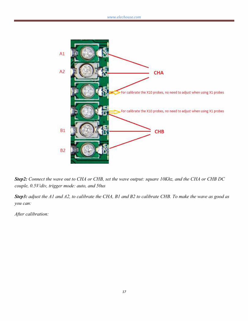
Step1: Open the back cover, and you will see 6 adjustable capacitors.
www.elechouse.com
17
Step2: Connect the wave out to CHA or CHB, set the wave output: square 10Khz, and the CHA or CHB DC
couple, 0.5V/div, trigger mode: auto, and 50us
Step3: adjust the A1 and A2, to calibrate the CHA, B1 and B2 to calibrate CHB. To make the wave as good as
you can:
After calibration:

www.elechouse.com
18
Calibrate the DS203 (for app2.35 or above)
If you update your App to app2.35, you might need to do this calibration. A standard voltmeter and an
adjustable voltage source are needed for calibrating the DS203.
In working state, when the main menu CH (A) was selected, pressing the calibrate button about 2s to begin the
calibration of CH (A). While main menu CH (B) was selected, pressing the calibrate button about 2s to begin
the calibration of CH (B).
1. Connect the probe to ground. An to 0.00 with Navigator A. Then,
press down the Navigator A to jump to - -1 or +1 can be
acceptable too). Press down the Navigator A, the cursor jumps back , make
sure the 2 cells are 0.00(or +1 ,-1).
2. With the probe grounded. Jump to the 0.1v row with Navigator B. A -
0.00. DO NOT adjust the - , as it can not be adjusted.
3. Repeat the above operation. Now, the result should be (probe ground):
CHA ZERO DIFF Voltage
50mv 0.00 0.00(or +1,1)
0.1v 0.00
0.2v 0.00
0.5v 0.00
1v 0.00
2v 0.00
5v 0.00
10v 0.00

www.elechouse.com
19
4. Press the Navigator B source to 250mv-300mv as the
prompt (you can measure the voltage with a voltmeter to get the voltage precisely), connect it to the
DSO channel you are calibrating, and adju you measured. For example, if
your source was 290mv, adjust the cell - pull the Navigator B to jump
to the other row.
5. For the other row, repeat the operation as the prompt. For example, my voltage source for all the row
was: 300mv, 600mv, 1.2v, 3v, 6v, 10v, 10v, 10v (I do not have a voltage source of 30v and 60v, so ,I use
10v for the row 5v and row 10v) .
CHA ZERO DIFF Voltage
50mv 0.00 0.00(or +1,1) 300mv
0.1v 0.00 600mv
0.2v 0.00 1.2v
0.5v 0.00 3.00v
1v 0.00 6.00v
2v 0.00 10.00v
5v 0.00 10.00v
10v 0.00 10.00v
6. After all this have been done, push the Navigator B to the exit mode. There are 3 models: exit without
calibration/exit with calibration/exit
Navigator A. And then press the calibrate button.
7. The DS203 the calibration successfully.
Assemble
Step1
Split the EVA sheet into two, stick one on the back of decorative aluminum board, and attach the other one to
the surface of the shell to protect the LCD screen.

www.elechouse.com
20
Step2
Note the direction when attaching it, a notch there for the square hole can help you. It is only when you finish
the sticking that you can tear up the protection paper for the back-adhesive paper.
Step3
When approaching the glass to the top shell, do not tear up the protection film and prevent dust during the
installation process.

www.elechouse.com
21
Step4
Stick the decorative aluminum board on the battery shell.
Step5

www.elechouse.com
22
Step6
Stick the EVA adhesive sheet on the battery shield.
Step7
Install the battery shield

www.elechouse.com
23
Step8
Install the keys
Step9
Install the main board in the bottom shell
www.elechouse.com
24
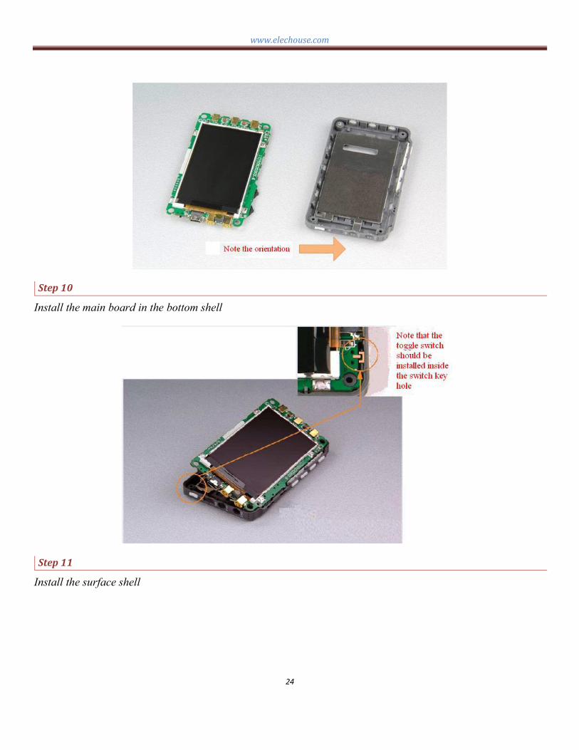
Step10
Install the main board in the bottom shell
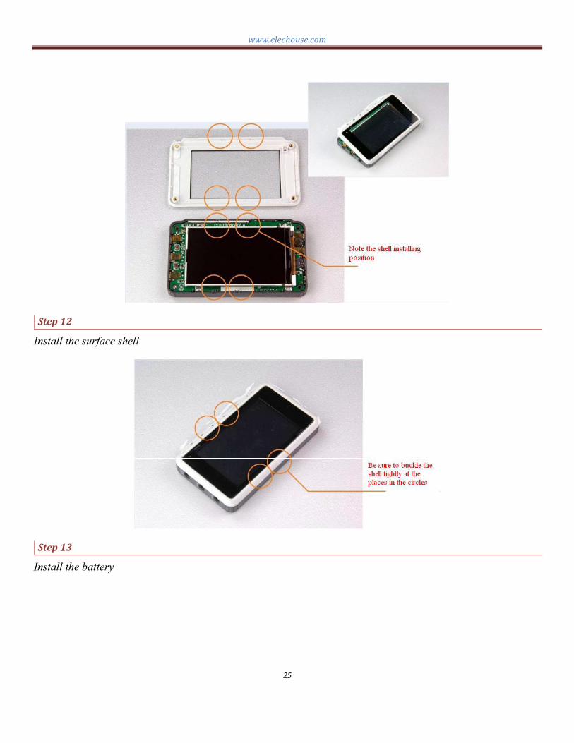
Step11
Install the surface shell
www.elechouse.com
25
Step12
Install the surface shell
Step13
Install the battery

www.elechouse.com
26
Step14
Install the battery shield
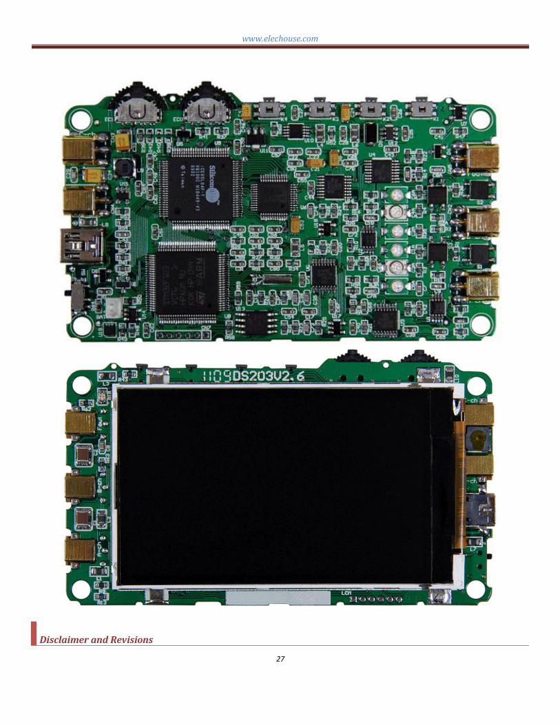
Technique Information
Please note: schematic diagram is attached on the page.
www.elechouse.com
27
DisclaimerandRevisions

www.elechouse.com
28
The information in this document may change without notice.
Revision History
Rev. Date Author DescriptionA May. 22nd, 2011 Wilson Shen Initial version