MANUAL TRANSMISSION MT - ZONE DATSUN.FR
61
MANUAL TRANSMISSION SECTION MT CONTENTS FS5W71C PREPARATION ................................................................2 Special Service Tools ..................................................2 Commercial Service Tools ...........................................3 FS5R30A PREPARATION ................................................................4 Special Service Tools ..................................................4 Commercial Service Tool .............................................5 FS5W71C DESCRIPTION .................................................................6 Cross-sectional View - 2WD Model .............................6 Cross-sectional View - 4WD Model .............................7 FS5R30A DESCRIPTION .................................................................8 Cross-sectional View - 4WD Model .............................8 FS5W71C ON-VEHICLE SERVICE ..................................................9 Replacing Rear Oil Seal - 2WD Model .......................9 Position Switch Check .................................................9 FS5R30A ON-VEHICLE SERVICE ................................................10 Position Switch Check - 4WD Model ........................10 FS5W71C & FS5R30A REMOVAL AND INSTALLATION .................................. 11 Removal ..................................................................... 11 Installation ..................................................................12 FS5W71C MAJOR OVERHAUL .....................................................14 Case Components .....................................................14 Gear Components - 2WD Model ...............................15 Gear Components - 4WD Model ...............................16 Shift Control Components - 2WD Model ...................17 Shift Control Components - 4WD Model ...................18 DISASSEMBLY ..............................................................19 Case Components .....................................................19 Shift Control Components .........................................20 Gear Components .....................................................20 INSPECTION..................................................................23 Shift Control Components .........................................23 Gear Components .....................................................23 ASSEMBLY ....................................................................25 Gear Components .....................................................25 Shift Control Components .........................................31 Case Components .....................................................32 FS5R30A MAJOR OVERHAUL .....................................................34 Case Components .....................................................34 Gear Components .....................................................35 Shift Control Components .........................................37 DISASSEMBLY ..............................................................38 Case Components .....................................................38 Shift Control Components .........................................39 Gear Components .....................................................40 INSPECTION..................................................................44 Shift Control Components .........................................44 Gear Components .....................................................44 ASSEMBLY ....................................................................46 Gear Components .....................................................46 Shift Control Components .........................................54 Case Components .....................................................54
Transcript of MANUAL TRANSMISSION MT - ZONE DATSUN.FR
MANUAL TRANSMISSION
SECTIONMTCONTENTS
FS5W71C
PREPARATION ................................................................2Special Service Tools ..................................................2Commercial Service Tools ...........................................3
FS5R30A
PREPARATION ................................................................4Special Service Tools ..................................................4Commercial Service Tool.............................................5
FS5W71C
DESCRIPTION .................................................................6Cross-sectional View - 2WD Model.............................6Cross-sectional View - 4WD Model.............................7
FS5R30A
DESCRIPTION .................................................................8Cross-sectional View - 4WD Model.............................8
FS5W71C
ON-VEHICLE SERVICE ..................................................9Replacing Rear Oil Seal - 2WD Model .......................9Position Switch Check .................................................9
FS5R30A
ON-VEHICLE SERVICE ................................................10Position Switch Check - 4WD Model ........................10
FS5W71C & FS5R30A
REMOVAL AND INSTALLATION ..................................11Removal.....................................................................11Installation..................................................................12
FS5W71C
MAJOR OVERHAUL .....................................................14Case Components .....................................................14Gear Components - 2WD Model...............................15Gear Components - 4WD Model...............................16Shift Control Components - 2WD Model...................17Shift Control Components - 4WD Model...................18
DISASSEMBLY ..............................................................19Case Components .....................................................19Shift Control Components .........................................20Gear Components .....................................................20
INSPECTION..................................................................23Shift Control Components .........................................23Gear Components .....................................................23
ASSEMBLY ....................................................................25Gear Components .....................................................25Shift Control Components .........................................31Case Components .....................................................32
FS5R30A
MAJOR OVERHAUL .....................................................34Case Components .....................................................34Gear Components .....................................................35Shift Control Components .........................................37
DISASSEMBLY ..............................................................38Case Components .....................................................38Shift Control Components .........................................39Gear Components .....................................................40
INSPECTION..................................................................44Shift Control Components .........................................44Gear Components .....................................................44
ASSEMBLY ....................................................................46Gear Components .....................................................46Shift Control Components .........................................54Case Components .....................................................54

FS5W71C & FS5R30A
SERVICE DATA AND SPECIFICATIONS (SDS) ..........57General Specifications...............................................57
FS5W71C
SERVICE DATA AND SPECIFICATIONS (SDS) ..........58Inspection and Adjustment ........................................58
FS5R30A
SERVICE DATA AND SPECIFICATIONS (SDS) ..........59Inspection and Adjustment ........................................59
GI
MA
EM
LC
EC
FE
CL
TF
PD
FA
RA
BR
ST
RS
BT
HA
EL
IDX
CONTENTS (Cont’d)

Special Service Tools
Tool numberTool name
Description
ST23810001Adapter setting plate
NT407
Fixing adapter plate with gear assembly
a: 166 mm (6.54 in)b: 270 mm (10.63 in)
KV32101330Puller
NT408
Removing OD mainshaft bearing
a: 447 mm (17.60 in)b: 100 mm (3.94 in)
KV31100401Transmission press stand
NT068
Pressing counter gear and mainshaft
ST22520000Wrench
NT409
Tightening mainshaft lock nut
a: 100 mm (3.94 in)b: 41 mm (1.61 in)
ST23540000Pin punch
NT442
Removing and installing fork rod retaining pin
a: 2.3 mm (0.091 in) dia.b: 4 mm (0.16 in) dia.
ST30031000Puller
NT411
Removing and installing 1st gear bushingRemoving main drive gear bearing
a: 90 mm (3.54 in) dia.b: 50 mm (1.97 in) dia.
ST23860000Drift
NT065
Installing counter drive gear
a: 38 mm (1.50 in) dia.b: 33 mm (1.30 in) dia.
ST22360002Drift
NT065
Installing counter gear front and rear endbearings
a: 29 mm (1.14 in) dia.b: 23 mm (0.91 in) dia.
ST22350000Drift
NT065
Installing OD gear bushing
a: 34 mm (1.34 in) dia.b: 28 mm (1.10 in) dia.
ST23800000Drift
NT065
Installing front cover oil seal
a: 44 mm (1.73 in) dia.b: 31 mm (1.22 in) dia.
PREPARATION FS5W71C
MT-2
Tool numberTool name
Description
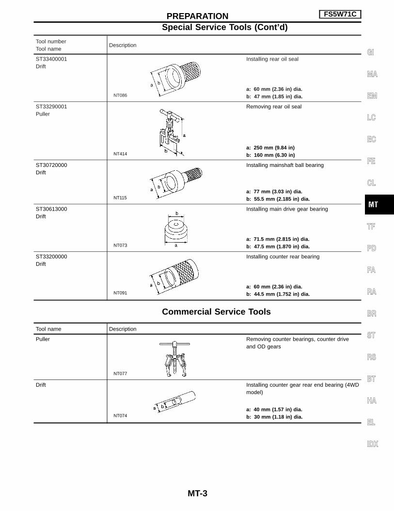
ST33400001Drift
NT086
Installing rear oil seal
a: 60 mm (2.36 in) dia.b: 47 mm (1.85 in) dia.
ST33290001Puller
NT414
Removing rear oil seal
a: 250 mm (9.84 in)b: 160 mm (6.30 in)
ST30720000Drift
NT115
Installing mainshaft ball bearing
a: 77 mm (3.03 in) dia.b: 55.5 mm (2.185 in) dia.
ST30613000Drift
NT073
Installing main drive gear bearing
a: 71.5 mm (2.815 in) dia.b: 47.5 mm (1.870 in) dia.
ST33200000Drift
NT091
Installing counter rear bearing
a: 60 mm (2.36 in) dia.b: 44.5 mm (1.752 in) dia.
Commercial Service Tools
Tool name Description
Puller
NT077
Removing counter bearings, counter driveand OD gears
Drift
NT074
Installing counter gear rear end bearing (4WDmodel)
a: 40 mm (1.57 in) dia.b: 30 mm (1.18 in) dia.
PREPARATION FS5W71C
Special Service Tools (Cont’d)
MT-3
GI
MA
EM
LC
EC
FE
CL
TF
PD
FA
RA
BR
ST
RS
BT
HA
EL
IDX

Special Service Tools
Tool numberTool name
Description
ST23540000Pin punch
NT442
Removing and installing retaining pin
a: 2.3 mm (0.091 in) dia.b: 4 mm (0.16 in) dia.
ST30031000Puller
NT411
Removing 1st & 2nd synchronizer assemblyRemoving counter gear rear thrust bearingRemoving main drive bearing
a: 90 mm (3.54 in) dia.b: 50 mm (1.97 in) dia.
ST33230000Drift
NT084
Removing mainshaft and counter gear
a: 51 mm (2.01 in) dia.b: 28.5 mm (1.122 in) dia.
ST22350000Drift
NT065
Removing counter gear front bearing(Use with KV38100300)
a: 34 mm (1.34 in) dia.b: 28 mm (1.10 in) dia.
KV38100300Drift
NT065
Removing counter gear front bearing(Use with ST22350000)Installing counter gear rear bearing
a: 54 mm (2.13 in) dia.b: 32 mm (1.26 in) dia.
ST30720000Drift
NT115
Removing mainshaft front bearingInstalling mainshaft front bearing
a: 77 mm (3.03 in) dia.b: 55.5 mm (2.185 in) dia.
ST33210000Drift
NT084
Installing counter gear front bearingInstalling front cover oil seal
a: 44 mm (1.73 in) dia.b: 24.5 mm (0.965 in) dia.
ST30613000Drift
NT073
Installing main drive gear bearing
a: 72 mm (2.83 in) dia.b: 48 mm (1.89 in) dia.
ST37750000Drift
NT065
Removing counter gear rear bearingInstalling OD gear bushingRemoving and installing mainshaft rear bear-ingInstalling reverse coneInstalling reverse counter gearInstalling counter gear rear end bearing
a: 40 mm (1.57 in) dia.b: 31 mm (1.22 in) dia.
PREPARATION FS5R30A
MT-4

Tool numberTool name
Description
ST22452000Drift
NT065
Installing reverse hub
a: 45 mm (1.77 in) dia.b: 36 mm (1.42 in) dia.
ST33220000Drift
NT084
Installing mainshaft rear bearing
a: 37 mm (1.46 in) dia.b: 22 mm (0.87 in) dia.
Commercial Service Tool
Tool name Description
Puller
NT077
Removing counter gear rear end bearingRemoving reverse synchronizer hubRemoving reverse counter gear
PREPARATION FS5R30A
Special Service Tools (Cont’d)
MT-5
GI
MA
EM
LC
EC
FE
CL
TF
PD
FA
RA
BR
ST
RS
BT
HA
EL
IDX

Cross-sectional View — 2WD Model
SMT153D
DESCRIPTION FS5W71C
MT-6

Cross-sectional View — 4WD Model
SMT154D
DESCRIPTION FS5W71C
MT-7
GI
MA
EM
LC
EC
FE
CL
TF
PD
FA
RA
BR
ST
RS
BT
HA
EL
IDX

Cross-sectional View — 4WD Model
SMT870CA
DESCRIPTION FS5R30A
MT-8

Replacing Rear Oil Seal — 2WD ModelREMOVAL1. Remove the propeller shaft. Refer to PD section (“Removal and
Installation”, “PROPELLER SHAFT”).2. Remove rear oil seal using Tool.I Always replace with a new seal once it has been removed.
INSTALLATION1. Install new oil seal until it stops.I Apply multi-purpose grease to seal lip of oil seal before
installing.2. Install any part removed.
Position Switch CheckI Check continuity.
Switch Gear position Continuity
Back-up lamp switchReverse Yes
Except reverse No
Neutral position switch(KA24E engine modelonly)
Neutral Yes
Except neutral No
SMT476AA
SMT477AA
SMT451BD
ON-VEHICLE SERVICE FS5W71C
MT-9
GI
MA
EM
LC
EC
FE
CL
TF
PD
FA
RA
BR
ST
RS
BT
HA
EL
IDX

Position Switch Check — 4WD ModelSwitch Gear position Continuity
Back-up lamp switchReverse Yes
Except reverse No
SMT155D
ON-VEHICLE SERVICE FS5R30A
MT-10

Removal2WD MODEL1. Remove battery negative terminal and starter motor. Refer to
EL section (“Removal and Installation”, “STARTING SYSTEM”).2. Remove transmission shift knob, dust rubber boot, hole cover
and transmission shift lever.3. Remove propeller shaft. Refer to PD section (“Removal and
Installation”, “PROPELLER SHAFT”).4. Remove back-up lamp switch and neutral position switch har-
ness connectors.5. Remove clutch operating cylinder from transmission. Refer to
CL section (“Operating Cylinder”, “HYDRAULIC CLUTCHCONTROL”).
I Insert plug into rear oil seal after removing propeller shaft.I Be careful not to damage spline, sleeve yoke and rear oil
seal when removing propeller shaft.
6. Support engine by placing a jack under oil pan.I Do not place jack under oil pan drain plug.7. Separate transmission from engine.WARNING:Support manual transmission while removing it.8. Lower transmission.
4WD MODEL1. Remove battery negative terminal and starter motor. Refer to
EL section (“Removal and Installation”, “STARTING SYSTEM”).2. Remove transfer control knob, dust rubber boot, hole cover,
transmission shift lever and transfer control lever.3. Remove front and rear propeller shafts. Refer to PD section
(“Removal and Installation”, “PROPELLER SHAFT”).4. Remove torsion bar springs. Refer to FA section (“Torsion Bar
Spring”, “FRONT SUSPENSION”). Then remove second cross-member.
5. Remove clutch operating cylinder from transmission. Refer toCL section (“Operating Cylinder”, “HYDRAULIC CLUTCHCONTROL”).
6. Remove back-up lamp switch and neutral position switch har-ness connector.
I Insert plug into front and rear oil seals of transfer afterremoving propeller shafts.
I Be careful not to damage splines, sleeve yokes and frontand rear oil seals of transfer when removing propellershafts.
7. Remove engine gusset (FS5R30A model only).8. Support transfer and remove center member.9. Support transmission and remove engine rear member.
SMT099A
SMT478A
REMOVAL AND INSTALLATION FS5W71C & FS5R30A
MT-11
GI
MA
EM
LC
EC
FE
CL
TF
PD
FA
RA
BR
ST
RS
BT
HA
EL
IDX

10. Separate transmission and transfer from engine.11. Lower transmission and transfer.
InstallationI Apply sealant to areas shown below: — 4WD model
SMT782CA
REMOVAL AND INSTALLATION FS5W71C & FS5R30A
Removal (Cont’d)
MT-12

I Tighten bolt securing transmission.I NA20S, Z24S and KA24E engine models
Bolt No. Tightening torque N⋅m (kg-m, ft-lb) � mm (in)
q1 39 - 49 (4.0 - 5.0, 29 - 36) 65 (2.56)
q2 39 - 49 (4.0 - 5.0, 29 - 36) 58 (2.28)
q3 * 16 - 22 (1.6 - 2.2, 12 - 16) 25 (0.98)
q4 16 - 22 (1.6 - 2.2, 12 - 16) 16 (0.63)
*: With nut
I TD27 engine model
Bolt No. Tightening torque N⋅m (kg-m, ft-lb) � mm (in)
q1 39 - 49 (4.0 - 5.0, 29 - 36) 58 (2.28)
q2 18 - 22 (1.8 - 2.2, 13 - 16) 16 (0.63)
I QD32 engine model
Bolt No. Tightening torque N⋅m (kg-m, ft-lb) � mm (in)
q1 39 - 49 (4.0 - 5.0, 29 - 36) 58 (2.28)
q2 29 - 39 (3.0 - 4.0, 22 - 29) 16 (0.63)
q3 * 29 - 39 (3.4 - 4.0, 22 - 29) 100 (3.94)
q4 18 - 22 (1.8 - 2.2, 13 - 16) 16 (0.63)
Engine gusset 29 - 39 (3.0 - 4.0, 22 - 29) 35 (1.38)
*: With nut
I Tighten bolts with T/M bracket, crossmember and frame.Unit: N⋅m (kg-m, ft-lb)
Bolt No. 2WD & 4WD Note
q159 - 69
(6.0 - 7.0, 43 - 51)Crossmember to frame
q241 - 52
(4.2 - 5.3, 30 - 38)T/M bracket to crossmember
q368 - 87
(6.9 - 8.9, 50 - 64)T/M to T/M bracket
SMT305C
SMT204D
SMT156D
SMT192D
REMOVAL AND INSTALLATION FS5W71C & FS5R30A
Installation (Cont’d)
MT-13
GI
MA
EM
LC
EC
FE
CL
TF
PD
FA
RA
BR
ST
RS
BT
HA
EL
IDX

Case Components
SMT157D
MAJOR OVERHAUL FS5W71C
MT-14

Gear Components — 2WD Model
SMT158D
MAJOR OVERHAUL FS5W71C
MT-15
GI
MA
EM
LC
EC
FE
CL
TF
PD
FA
RA
BR
ST
RS
BT
HA
EL
IDX

Gear Components — 4WD Model
SMT159D
MAJOR OVERHAUL FS5W71C
MT-16

Shift Control Components — 2WD ModelCAUTION:To avoid damage when replacing shift knob, remove shift leverwith knob, as assembled.
SMT160D
MAJOR OVERHAUL FS5W71C
MT-17
GI
MA
EM
LC
EC
FE
CL
TF
PD
FA
RA
BR
ST
RS
BT
HA
EL
IDX

Shift Control Components — 4WD ModelCAUTION:To avoid damage when replacing shift knob, remove shift leverwith knob, as assembled.
SMT561AA
MAJOR OVERHAUL FS5W71C
MT-18

Case Components1. Remove rear extension.a. Remove control housing, check ball, return spring, plug, select
check plunger and return springs.
b. Drive out striking arm retaining pin.c. Remove striking arm from striking rod.
d. Remove rear extension by lightly tapping it.
2. Remove front cover, gasket, shim of counter gear front bearing,and snap ring of main drive gear ball bearing.
3. Remove transmission case by tapping lightly. Then separatetransmission case from front adapter plate.
SMT161D
SMT162D
SMT163D
SMT164D
SMT165D
DISASSEMBLY FS5W71C
MT-19
GI
MA
EM
LC
EC
FE
CL
TF
PD
FA
RA
BR
ST
RS
BT
HA
EL
IDX

4. Remove front cover oil seal.I Be careful not to damage front cover mating surface.
Shift Control Components1. Set up Tool on adapter plate.2. Remove striking rod from adapter plate.3. Remove check ball plugs, check springs, and check balls.
4. Drive out retaining pins. Then drive out fork rods and removeinterlock balls.
5. Draw out 3rd & 4th and OD & reverse fork rods.
Gear Components1. Before removing gears and shafts, measure each gear end
play.Gear end play:
Refer to SDS, MT-58.If not within specification, disassemble and check contact sur-face of gear to hub, washer, bushing, needle bearing and shaft.
SMT166D
SMT545AA
SMT984-A
SMT789A
SMT025
DISASSEMBLY FS5W71C
Case Components (Cont’d)
MT-20

2. Mesh 2nd and reverse gear, then draw out counter gear frontbearing with suitable puller.
3. Remove snap ring and then remove sub-gear bracket, sub-gearspring and sub-gear.
4. Draw out counter drive gear with main drive gear assembly withsuitable puller.
I When drawing out main drive gear assembly, be careful notto drop pilot bearing and baulk ring.
5. Remove snap ring and draw out 3rd & 4th synchronizer and 3rdgear.
6. Remove rear side components on mainshaft and counter gearas follows.
a. Release staking on counter gear lock nut and mainshaft locknut and loosen these nuts.
I Mainshaft lock nut: Left-hand thread
b. Pull out OD counter gear with counter gear rear end bearingwith suitable puller.
c. Draw out reverse counter gear and reverse counter gearspacer.
d. Remove snap rings from reverse idler shaft and draw outreverse idler gear, reverse idler thrust washers and reverseidler gear bearing.
e. Remove speedometer drive gear and steel ball (2WD modelonly).
f. Remove snap ring and pull out OD mainshaft bearing, thenremove snap ring.
g. Remove mainshaft lock nut.h. Remove steel roller and thrust washer.i. Remove roller bearing and washer.j. Remove OD main gear, needle bearing and baulk ring (OD).k. Remove OD coupling sleeve (4WD) and shifting inserts.l. Remove reverse main gear (2WD) and shifting inserts.
SMT174A
SMT167D
SMT198D
SMT164A
SMT165AA
DISASSEMBLY FS5W71C
Gear Components (Cont’d)
MT-21
GI
MA
EM
LC
EC
FE
CL
TF
PD
FA
RA
BR
ST
RS
BT
HA
EL
IDX

m. Press out mainshaft and counter gear alternately.I Press down mainshaft and counter gear alternately and
carefully. Do not allow gears attached to mainshaft andcounter gear underneath adapter plate to hit each other.
7. Remove front side components on mainshaft.a. Remove 1st gear washer and steel ball.b. Remove 1st main gear and 1st gear needle bearing.I Be careful not to lose steel ball.
c. Press out 2nd main gear together with 1st gear bushing and 1st& 2nd synchronizer assembly.
d. Remove mainshaft front snap ring.
e. Press out 3rd main gear together with 3rd & 4th synchronizerassembly and 3rd gear needle bearing.
8. Remove main drive gear bearing.a. Remove main drive gear snap ring and spacer.b. Press out main drive gear bearing.
SMT751A
SMT383A
SMT384A
SMT385A
SMT420AA
DISASSEMBLY FS5W71C
Gear Components (Cont’d)
MT-22
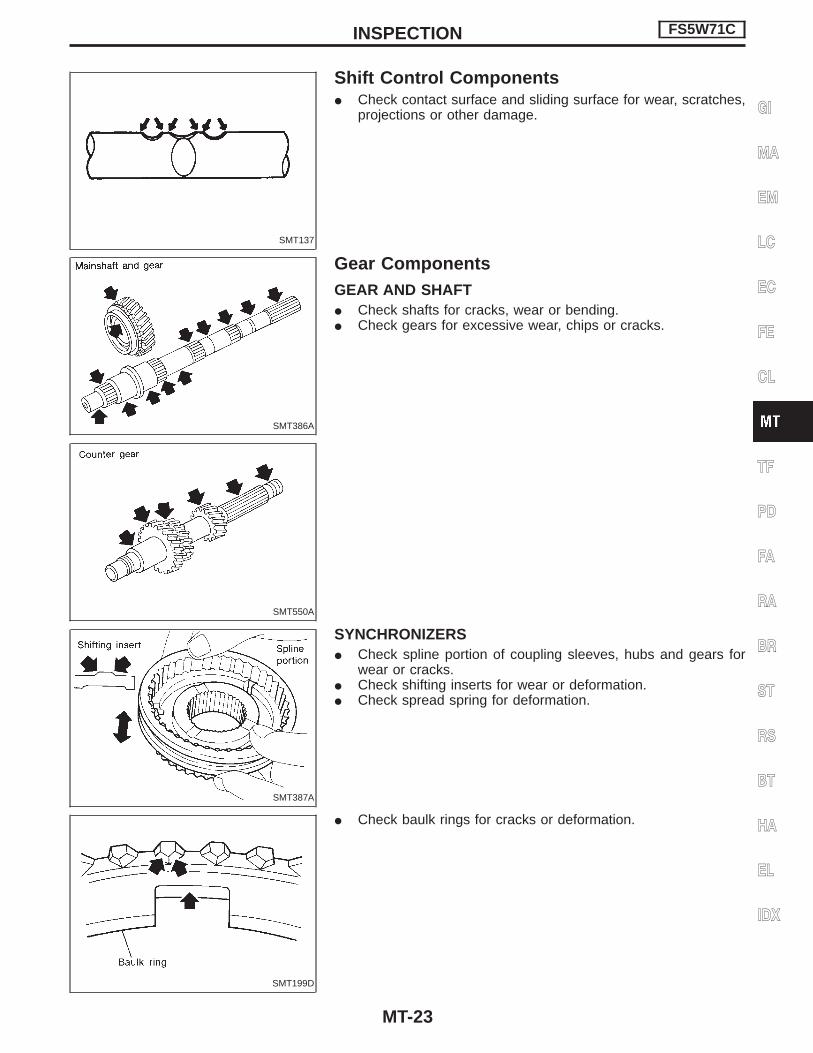
Shift Control ComponentsI Check contact surface and sliding surface for wear, scratches,
projections or other damage.
Gear ComponentsGEAR AND SHAFTI Check shafts for cracks, wear or bending.I Check gears for excessive wear, chips or cracks.
SYNCHRONIZERSI Check spline portion of coupling sleeves, hubs and gears for
wear or cracks.I Check shifting inserts for wear or deformation.I Check spread spring for deformation.
I Check baulk rings for cracks or deformation.
SMT137
SMT386A
SMT550A
SMT387A
SMT199D
INSPECTION FS5W71C
MT-23
GI
MA
EM
LC
EC
FE
CL
TF
PD
FA
RA
BR
ST
RS
BT
HA
EL
IDX

I Measure clearance between baulk ring and gear.Clearance between baulk ring and gear:
Refer to SDS, MT-58.I If the clearance is smaller than the wear limit, replace baulk
ring.
BEARINGSI Make sure bearings roll freely and are free from noise, crack,
pitting or wear.
SMT140
SMT418A
INSPECTION FS5W71C
Gear Components (Cont’d)
MT-24

Gear Components1. Install bearings into case components.
2. Assemble adapter plate parts.I Install bearing retainer.a. Insert reverse idler shaft, then install bearing retainer.
b. Tighten each screw, then stake it at two points.
SMT168D
SMT175D
SMT674C
ASSEMBLY FS5W71C
MT-25
GI
MA
EM
LC
EC
FE
CL
TF
PD
FA
RA
BR
ST
RS
BT
HA
EL
IDX
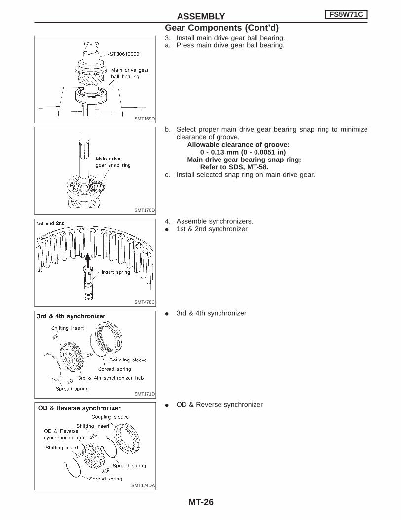
3. Install main drive gear ball bearing.a. Press main drive gear ball bearing.
b. Select proper main drive gear bearing snap ring to minimizeclearance of groove.
Allowable clearance of groove:0 - 0.13 mm (0 - 0.0051 in)
Main drive gear bearing snap ring:Refer to SDS, MT-58.
c. Install selected snap ring on main drive gear.
4. Assemble synchronizers.I 1st & 2nd synchronizer
I 3rd & 4th synchronizer
I OD & Reverse synchronizer
SMT169D
SMT170D
SMT478C
SMT171D
SMT174DA
ASSEMBLY FS5W71C
Gear Components (Cont’d)
MT-26

5. Assemble front side components to mainshaft.a. Install 2nd main gear, needle bearing and 1st & 2nd synchro-
nizer assembly, then press 1st gear bushing on mainshaft.b. Install 1st main gear.
c. Install steel ball and 1st gear washer.I Before installation, apply multi-purpose grease to steel ball
and to both sides of the 1st gear washer.
6. Install mainshaft and counter gear on adapter plate and maindrive gear on mainshaft as follows:
a. Press mainshaft assembly into adapter plate using Tool.
b. Press counter gear into adapter plate using Tool.c. Install 3rd main gear and needle bearing, then press 3rd & 4th
synchronizer assembly onto mainshaft.
I Pay attention to the direction of 3rd & 4th synchronizerhub.
SMT752A
TM358
TM439-A
SMT750-A
SMT172D
ASSEMBLY FS5W71C
Gear Components (Cont’d)
MT-27
GI
MA
EM
LC
EC
FE
CL
TF
PD
FA
RA
BR
ST
RS
BT
HA
EL
IDX
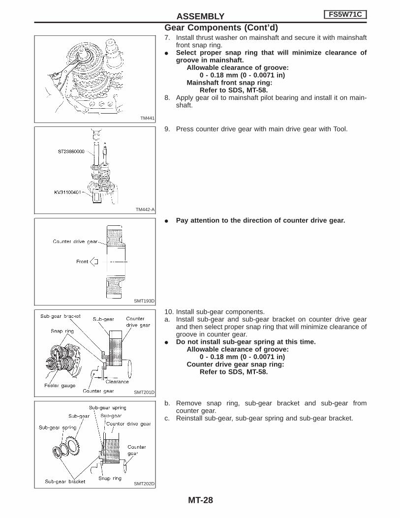
7. Install thrust washer on mainshaft and secure it with mainshaftfront snap ring.
I Select proper snap ring that will minimize clearance ofgroove in mainshaft.
Allowable clearance of groove:0 - 0.18 mm (0 - 0.0071 in)
Mainshaft front snap ring:Refer to SDS, MT-58.
8. Apply gear oil to mainshaft pilot bearing and install it on main-shaft.
9. Press counter drive gear with main drive gear with Tool.
I Pay attention to the direction of counter drive gear.
10. Install sub-gear components.a. Install sub-gear and sub-gear bracket on counter drive gear
and then select proper snap ring that will minimize clearance ofgroove in counter gear.
I Do not install sub-gear spring at this time.Allowable clearance of groove:
0 - 0.18 mm (0 - 0.0071 in)Counter drive gear snap ring:
Refer to SDS, MT-58.
b. Remove snap ring, sub-gear bracket and sub-gear fromcounter gear.
c. Reinstall sub-gear, sub-gear spring and sub-gear bracket.
TM441
TM442-A
SMT193D
SMT201D
SMT202D
ASSEMBLY FS5W71C
Gear Components (Cont’d)
MT-28

11. Install selected counter drive gear snap ring.
12. Press counter gear front bearing onto counter gear.
13. Assemble parts at rear of adapter plate as follows:a. Install reverse idler gear to reverse idler shaft with spacers,
snap rings and needle bearing.I On 4WD models, install the reverse idler shaft with the
friction damper. Refer to “Gear Components — 4WDModel”, “MAJOR OVERHAUL”, MT-16.
b. Install insert retainer and OD & Reverse synchronizer to main-shaft.
I Pay attention to the direction of hub.
c. Install OD gear bushing with Tool.d. Install OD main gear, needle bearing.e. Install reverse counter gear spacer, reverse counter gear and
OD counter gear.I OD main gear and OD counter gear should be handled as
a matched set.f. Install washer, roller bearing, steel roller, thrust washer, steel
ball and speedometer drive gear (2WD).g. Tighten mainshaft lock nut temporarily.I Always use new lock nut.
TM366
TM443-A
SMT194D
SMT174DA
SMT531-A
ASSEMBLY FS5W71C
Gear Components (Cont’d)
MT-29
GI
MA
EM
LC
EC
FE
CL
TF
PD
FA
RA
BR
ST
RS
BT
HA
EL
IDX
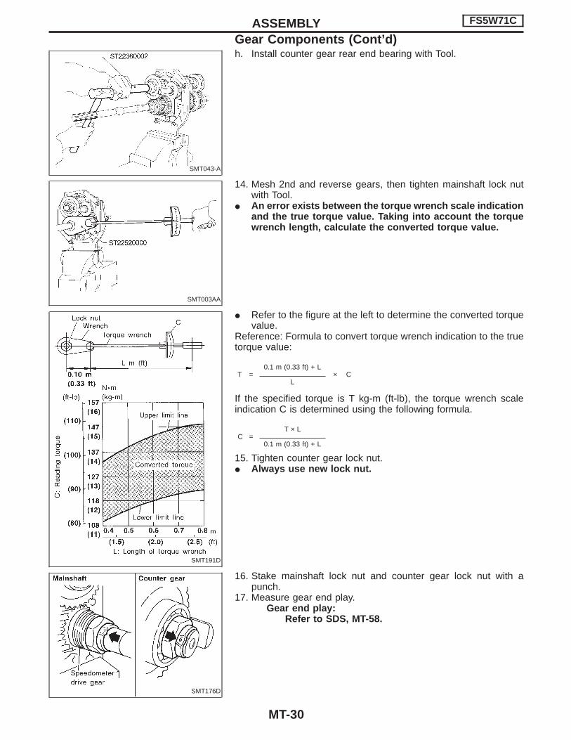
h. Install counter gear rear end bearing with Tool.
14. Mesh 2nd and reverse gears, then tighten mainshaft lock nutwith Tool.
I An error exists between the torque wrench scale indicationand the true torque value. Taking into account the torquewrench length, calculate the converted torque value.
I Refer to the figure at the left to determine the converted torquevalue.
Reference: Formula to convert torque wrench indication to the truetorque value:
T =0.1 m (0.33 ft) + L
× CL
If the specified torque is T kg-m (ft-lb), the torque wrench scaleindication C is determined using the following formula.
C =T × L
0.1 m (0.33 ft) + L
15. Tighten counter gear lock nut.I Always use new lock nut.
16. Stake mainshaft lock nut and counter gear lock nut with apunch.
17. Measure gear end play.Gear end play:
Refer to SDS, MT-58.
SMT043-A
SMT003AA
SMT191D
SMT176D
ASSEMBLY FS5W71C
Gear Components (Cont’d)
MT-30

18. Install snap ring and OD mainshaft bearing, then snap ring(2WD model only).
Allowable clearance:0 - 0.14 mm (0 - 0.0055 in)
OD mainshaft snap ring:Refer to SDS, MT-58.
Shift Control Components1. Install fork rods, interlock plunger, interlock balls and check
balls.
2. Install 1st & 2nd shift fork, then drive in retaining pin.
3. Install 3rd & 4th shift forks, then drive in retaining pin.
4. Install OD & Reverse shift fork, then drive in retaining pin.
SMT992-A
SMT177D
SMT178D
SMT179D
ASSEMBLY FS5W71C
Gear Components (Cont’d)
MT-31
GI
MA
EM
LC
EC
FE
CL
TF
PD
FA
RA
BR
ST
RS
BT
HA
EL
IDX

Case Components1. Install front cover oil seal using Tool.I Apply multi-purpose grease to seal lip.
2. Apply sealant to mating surface of transmission case.
3. Install gear assembly with adapter plate on transmission caseby lightly tapping with a soft hammer.
4. Install main drive gear ball bearing snap ring.
5. Apply sealant to mating surface of adapter plate.
SMT036-A
SMT061C
SMT013
SMT672A
SMT062C
ASSEMBLY FS5W71C
MT-32

6. Place shift forks in neutral position.7. Install striking lever and rod onto adapter plate and align strik-
ing lever with shift brackets.
8. Install rear extension.I Tighten mounting bolts equally in a criss-cross pattern.
9. Install striking arm lock pin.
10. Select counter gear front bearing shim.Allowable clearance (A) from bearing surface totransmission case:
0 - 0.16 mm (0 - 0.0063 in)Counter gear front bearing shim:
Refer to SDS, MT-58.11. Install gasket and front cover.
12. Install return spring plugs, check ball, return springs and selectcheck plungers.
13. Install control housing and gasket.
SMT801B
SMT180D
SMT162D
SMT205D
SMT161D
ASSEMBLY FS5W71C
Case Components (Cont’d)
MT-33
GI
MA
EM
LC
EC
FE
CL
TF
PD
FA
RA
BR
ST
RS
BT
HA
EL
IDX
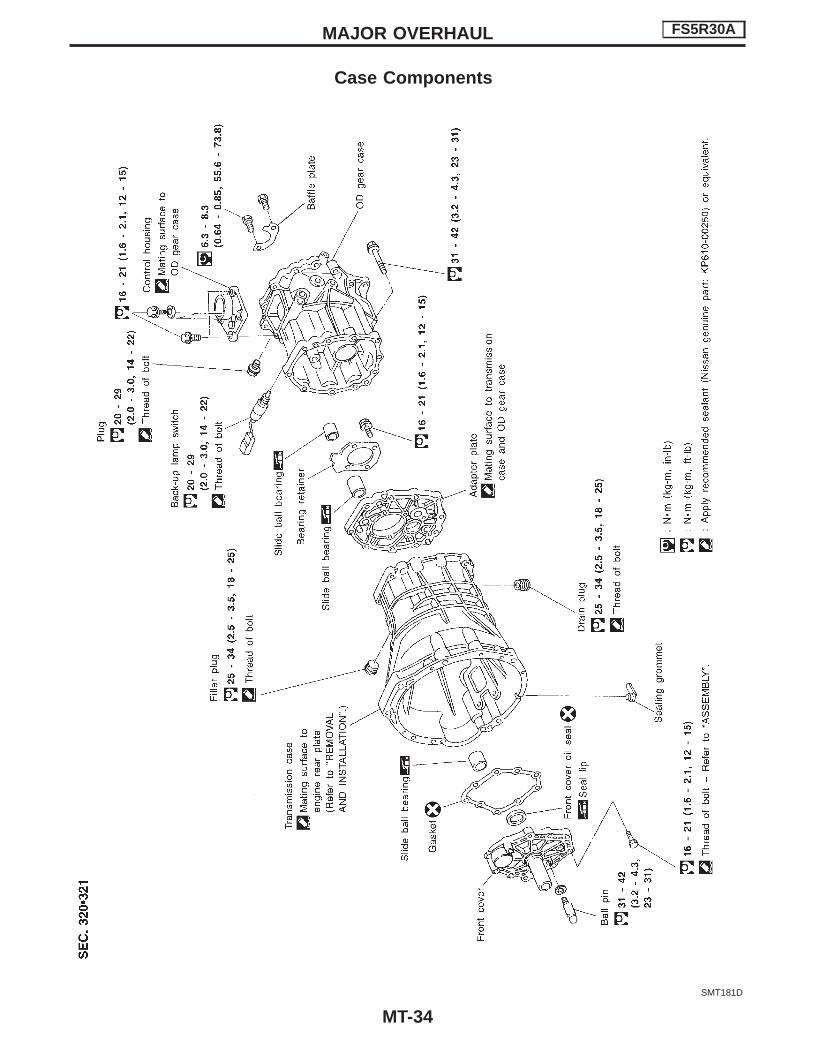
Case Components
SMT181D
MAJOR OVERHAUL FS5R30A
MT-34
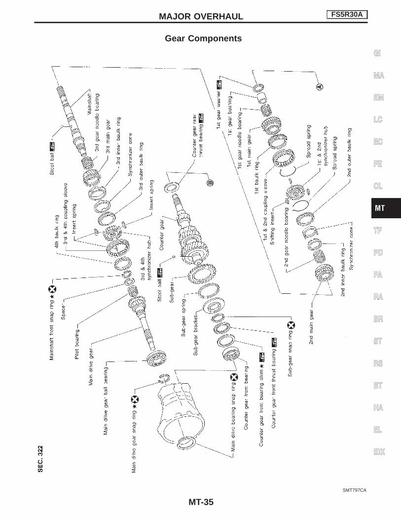
Gear Components
SMT797CA
MAJOR OVERHAUL FS5R30A
MT-35
GI
MA
EM
LC
EC
FE
CL
TF
PD
FA
RA
BR
ST
RS
BT
HA
EL
IDX

SMT182D
MAJOR OVERHAUL FS5R30A
Gear Components (Cont’d)
MT-36

Shift Control ComponentsCAUTION:To avoid damage when replacing shift knob, remove shift leverwith knob, as assembled.
SMT437BA
MAJOR OVERHAUL FS5R30A
MT-37
GI
MA
EM
LC
EC
FE
CL
TF
PD
FA
RA
BR
ST
RS
BT
HA
EL
IDX
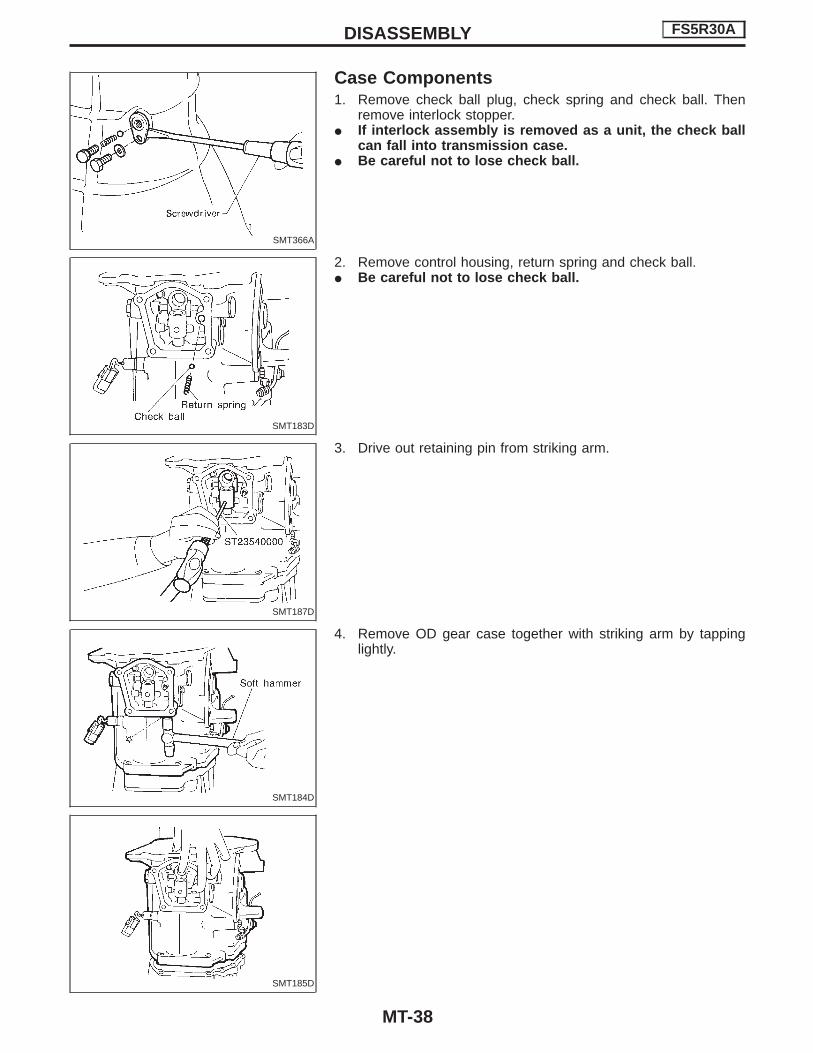
Case Components1. Remove check ball plug, check spring and check ball. Then
remove interlock stopper.I If interlock assembly is removed as a unit, the check ball
can fall into transmission case.I Be careful not to lose check ball.
2. Remove control housing, return spring and check ball.I Be careful not to lose check ball.
3. Drive out retaining pin from striking arm.
4. Remove OD gear case together with striking arm by tappinglightly.
SMT366A
SMT183D
SMT187D
SMT184D
SMT185D
DISASSEMBLY FS5R30A
MT-38

5. Remove front cover and gasket.
6. Remove stopper ring and main drive bearing snap ring.
7. Remove transmission case by tapping lightly.
8. Remove front cover oil seal.
Shift Control Components1. Mount adapter plate on vise.2. Remove OD & Reverse fork rod.
SMT370A
SMT371AA
SMT372A
SMT186D
SMT373A
DISASSEMBLY FS5R30A
Case Components (Cont’d)
MT-39
GI
MA
EM
LC
EC
FE
CL
TF
PD
FA
RA
BR
ST
RS
BT
HA
EL
IDX

3. Drive out retaining pin from striking lever.4. While pulling out striking rod, remove striking lever and striking
interlock. Then remove 1st & 2nd, 3rd & 4th and reverse shiftfork.
5. Drive out retaining pin from OD shift fork.6. Pull out OD fork rod and then remove OD shift fork.
Gear Components1. Before removing gears and shafts, measure each gear end
play.Gear end play:
Refer to SDS, MT-59.I If not within specification, disassemble and check contact sur-
face of gear to hub, washer, bushing, needle bearing and shaft.
2. Remove rear side components on mainshaft and counter gear.a. Remove reverse coupling sleeve.
b. Remove mainshaft rear snap ring and counter gear rear snapring.
c. Remove C-ring holder and mainshaft C-rings from mainshaft.Use punch and hammer to remove C-rings.
SMT374AA
SMT375AA
SMT376A
SMT463A
SMT377A
DISASSEMBLY FS5R30A
Shift Control Components (Cont’d)
MT-40

d. Pull out counter gear rear end bearing.e. Remove reverse idler gear and reverse idler thrust washers.
f. Pull out reverse main gear together with mainshaft spacer andreverse synchronizer hub. Then remove reverse gear needlebearings.
g. Pull out reverse counter gear.h. Remove OD coupling sleeve together with OD baulk ring,
reverse baulk ring and spring inserts.
i. Pull out reverse gear bushing.
j. Pull out OD counter gear together with reverse cone.
SMT378A
SMT380A
SMT773A
SMT770A
SMT771A
DISASSEMBLY FS5R30A
Gear Components (Cont’d)
MT-41
GI
MA
EM
LC
EC
FE
CL
TF
PD
FA
RA
BR
ST
RS
BT
HA
EL
IDX

3. Press out mainshaft and counter gear alternately.
4. Remove front side components on mainshaft.a. Remove 1st gear washer and steel ball.b. Remove 1st main gear and 1st gear needle bearing.I Be careful not to lose steel ball.
c. Press out 2nd main gear together with 1st gear bushing and 1st& 2nd synchronizer assembly.
d. Remove mainshaft front snap ring.
e. Press out 3rd main gear together with 3rd & 4th synchronizerassembly and 3rd gear needle bearing.
SMT772AB
SMT383A
SMT384A
SMT385A
DISASSEMBLY FS5R30A
Gear Components (Cont’d)
MT-42

5. Remove front side components on counter gear.a. Remove counter gear rear thrust bearing.
b. Remove sub-gear components.
6. Remove main drive gear bearing.a. Remove main drive gear snap ring and spacer.b. Press out main drive gear bearing.
7. Remove bearings from case components.
SMT404AA
SMT470A
SMT420AA
SMT063CB
DISASSEMBLY FS5R30A
Gear Components (Cont’d)
MT-43
GI
MA
EM
LC
EC
FE
CL
TF
PD
FA
RA
BR
ST
RS
BT
HA
EL
IDX

Shift Control ComponentsI Check contact surface and sliding surface for wear, scratches,
projections or other damage.
Gear ComponentsGEARS AND SHAFTSI Check shafts for cracks, wear or bending.I Check gears for excessive wear, chips or cracks.
SYNCHRONIZERSI Check spline portion of coupling sleeves, hubs, and gears for
wear or cracks.I Check baulk rings for cracks or deformation.I Check shifting inserts for wear or deformation.I Check insert springs for deformation.
Clearance between baulk ring and gear:Refer to SDS, MT-59.
I If the clearance is smaller than the wear limit, replace baulkring.
SMT398A
SMT386A
SMT423A
SMT387A
SMT140
INSPECTION FS5R30A
MT-44

I Measure wear of 2nd and 3rd baulk rings.a. Place baulk rings in position on synchronizer cone.b. While holding baulk rings against synchronizer cone as far as
it will go, measure dimensions “A” and “B”.Dimensions “A” and “B”:
Refer to SDS, MT-59.I If dimension “A” or “B” is smaller than the wear limit,
replace outer baulk ring, inner baulk ring and synchronizercone as a set.
I Measure wear of reverse baulk ring.a. Place baulk ring in position on reverse cone.b. While holding baulk ring against reverse cone as far as it will
go, measure dimension “A” with dial indicator.Dimension “A”:
Refer to SDS, MT-59.c. If dimension “A” is larger than the wear limit, replace baulk ring.
BEARINGSI Make sure bearings roll freely and are free from noise, crack,
pitting or wear.
SMT041BA
SMT042B
SMT424A
SMT418A
INSPECTION FS5R30A
Gear Components (Cont’d)
MT-45
GI
MA
EM
LC
EC
FE
CL
TF
PD
FA
RA
BR
ST
RS
BT
HA
EL
IDX

Gear Components1. Install bearings into case components.
2. Install main drive gear bearing.a. Press main drive gear bearing.b. Install main drive gear spacer.
c. Select proper main drive gear snap ring to minimize clearanceof groove.
Allowable clearance of groove:0 - 0.1 mm (0 - 0.004 in)
Main drive gear snap ring:Refer to SDS, MT-59.
d. Install selected snap ring on main drive gear.
SMT484CD
SMT425AA
SMT426A
ASSEMBLY FS5R30A
MT-46

3. Install components on counter gear.a. Install sub-gear components.I When installing sub-gear snap ring, tap sub-gear snap ring
into position on counter gear.
b. Install counter gear rear thrust bearing.
4. Install front side components on mainshaft.a. Assemble 1st & 2nd synchronizer.
b. Assemble 3rd & 4th synchronizer.
c. Press on 3rd & 4th synchronizer assembly together with 3rdmain gear and 3rd gear needle bearing.
I Pay attention to the direction of synchronizer assembly.
SMT577AA
SMT405A
SMT421A
SMT422A
SMT399A
ASSEMBLY FS5R30A
Gear Components (Cont’d)
MT-47
GI
MA
EM
LC
EC
FE
CL
TF
PD
FA
RA
BR
ST
RS
BT
HA
EL
IDX

d. Select proper snap ring to minimize clearance of groove.Allowable clearance of groove:
0 - 0.1 mm (0 - 0.004 in)Mainshaft front snap ring:
Refer to SDS, MT-59.e. Install selected snap ring on mainshaft.
f. Press on 1st & 2nd synchronizer assembly together with 2ndmain gear and 2nd gear needle bearing.
g. Press on 1st gear bushing using 1st gear washer.h. Install 1st main gear and needle bearing.
i. Install steel ball and 1st gear washer.I Apply multi-purpose grease to steel ball and 1st gear
washer before installing.
SMT188D
SMT401A
SMT402A
SMT403A
ASSEMBLY FS5R30A
Gear Components (Cont’d)
MT-48
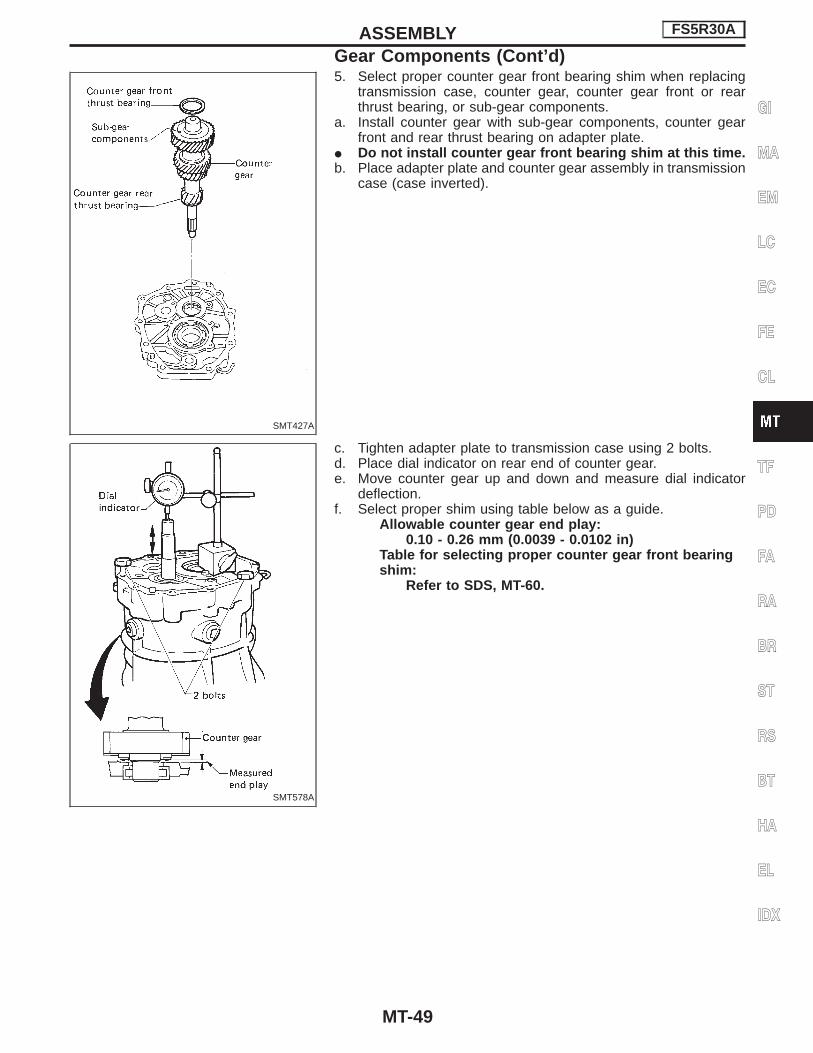
5. Select proper counter gear front bearing shim when replacingtransmission case, counter gear, counter gear front or rearthrust bearing, or sub-gear components.
a. Install counter gear with sub-gear components, counter gearfront and rear thrust bearing on adapter plate.
I Do not install counter gear front bearing shim at this time.b. Place adapter plate and counter gear assembly in transmission
case (case inverted).
c. Tighten adapter plate to transmission case using 2 bolts.d. Place dial indicator on rear end of counter gear.e. Move counter gear up and down and measure dial indicator
deflection.f. Select proper shim using table below as a guide.
Allowable counter gear end play:0.10 - 0.26 mm (0.0039 - 0.0102 in)
Table for selecting proper counter gear front bearingshim:
Refer to SDS, MT-60.
SMT427A
SMT578A
ASSEMBLY FS5R30A
Gear Components (Cont’d)
MT-49
GI
MA
EM
LC
EC
FE
CL
TF
PD
FA
RA
BR
ST
RS
BT
HA
EL
IDX

6. Select proper reverse idler rear thrust washer when replacingOD gear case, reverse idler gear, reverse idler shaft or reverseidler front thrust washer.
a. Install reverse idler gear, reverse idler needle bearings andreverse idler shaft into OD gear case.
I Do not install reverse idler rear thrust washer at this time.
b. Place dial indicator on front end of reverse idler shaft.c. Put straightedge on front surface of OD gear case as a stop-
per for reverse idler shaft.d. Move reverse idler shaft up and down and measure reverse
idler gear end play.Reverse idler gear end play:
0.30 - 0.53 mm (0.0118 - 0.0209 in)e. If not within specification, replace reverse idler rear thrust
washer with the other (A or B) and check again.Reverse idler rear thrust washer:
Refer to SDS, MT-60.
7. Install mainshaft and counter gear on adapter plate and maindrive gear on mainshaft.
a. Mount adapter plate on vise and apply multi-purpose grease tocounter gear rear bearing.
SMT189D
SMT433A
SMT438A
ASSEMBLY FS5R30A
Gear Components (Cont’d)
MT-50

b. Install mainshaft a little on mainshaft front bearing.I To allow for installation of counter gear, do not install
mainshaft completely.
c. Install counter gear on counter gear rear bearing and installmain drive gear, pilot bearing and spacer on mainshaft.
I When installing counter gear into counter gear rearbearing, push up on upper roller of counter gear rear bear-ing with screwdriver.
d. Install mainshaft and counter gear completely by tapping rearside of adapter plate and pulling mainshaft.
8. Install rear side components on mainshaft and counter gear.a. Install OD gear bushing while pushing on the front of counter
gear.
SMT440A
SMT441A
SMT442A
SMT443A
SMT444AA
ASSEMBLY FS5R30A
Gear Components (Cont’d)
MT-51
GI
MA
EM
LC
EC
FE
CL
TF
PD
FA
RA
BR
ST
RS
BT
HA
EL
IDX
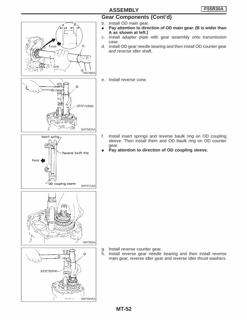
b. Install OD main gear.I Pay attention to direction of OD main gear. (B is wider than
A as shown at left.)c. Install adapter plate with gear assembly onto transmission
case.d. Install OD gear needle bearing and then install OD counter gear
and reverse idler shaft.
e. Install reverse cone.
f. Install insert springs and reverse baulk ring on OD couplingsleeve. Then install them and OD baulk ring on OD countergear.
I Pay attention to direction of OD coupling sleeve.
g. Install reverse counter gear.h. Install reverse gear needle bearing and then install reverse
main gear, reverse idler gear and reverse idler thrust washers.
SMT580A
SMT582AA
SMT571AA
SMT583A
SMT584AA
ASSEMBLY FS5R30A
Gear Components (Cont’d)
MT-52

i. Install reverse hub.I Pay attention to its direction.
j. Install counter gear rear end bearing.k. Separate adapter plate from transmission case and mount
adapter plate on vice again.
l. Select proper mainshaft C-ring to minimize clearance ofgroove.
Allowable clearance of groove:0 - 0.1 mm (0 - 0.004 in)
Mainshaft C-ring:Refer to SDS, MT-60.
m. Install selected C-ring, C-ring holder and mainshaft rear snapring.
SMT585AA
SMT587A
SMT452A
SMT454A
SMT453A
ASSEMBLY FS5R30A
Gear Components (Cont’d)
MT-53
GI
MA
EM
LC
EC
FE
CL
TF
PD
FA
RA
BR
ST
RS
BT
HA
EL
IDX

n. Install spacer and then select proper counter gear rear snapring to minimize clearance of groove.
Allowable clearance of groove:0 - 0.1 mm (0 - 0.004 in)
Counter gear rear snap ring:Refer to SDS, MT-60.
o. Install selected counter gear rear snap ring.
p. Install reverse coupling sleeve.I Pay attention to its direction.q. Measure each gear end play as a final check. Refer to SDS,
MT-59.
Shift Control Components1. Install OD fork rod and OD shift fork. Then install retaining pin
into OD shift fork.2. Install 1st & 2nd, 3rd & 4th and reverse shift fork onto coupling
sleeve.
3. Install striking rod into hole of shift forks, striking lever andinterlock and then install retaining pin into striking lever.
I Make sure that striking rod moves smoothly.
Case Components1. Install front cover oil seal.I Apply multi-purpose grease to seal lip.2. Install selected counter gear front bearing shim onto transmis-
sion case.I Apply multi-purpose grease.3. Apply sealant to mating surface of transmission case.
SMT455AA
SMT456A
SMT457A
SMT374AA
SMT393AA
ASSEMBLY FS5R30A
Gear Components (Cont’d)
MT-54

4. Install gear assembly onto transmission case.5. Install check spring and check ball into interlock stopper.I Apply multi-purpose grease to check ball.
6. Install interlock stopper assembly and then tighten check ballplug.
I Apply sealant to thread of check ball plug.
7. Install stopper ring and main drive bearing snap ring.
8. Install front cover and gasket.I Apply sealant to thread of 3 bolts shown left.9. Apply sealant to mating surface of adapter plate.
10. Install OD gear case together with striking arm.
SMT588A
SMT460A
SMT371AA
SMT459A
SMT185D
ASSEMBLY FS5R30A
Case Components (Cont’d)
MT-55
GI
MA
EM
LC
EC
FE
CL
TF
PD
FA
RA
BR
ST
RS
BT
HA
EL
IDX

11. Install retaining pin into striking arm.
12. Install return spring and check ball and then install control hous-ing.
I Apply sealant to mating surface of OD gear case.
13. Tighten control housing bolts.Bolt head size:
A bolts 12 mm (0.47 in)B bolts 13 mm (0.51 in)
SMT439B
SMT190D
SMT195D
ASSEMBLY FS5R30A
Case Components (Cont’d)
MT-56

General Specifications
Destination Australia, Middle East and General areasAustralia,
Middle East andGeneral areas
Australia andGeneral area
Applied model2WD 4WD
NA20S KA24E Z24S, TD27 Z24S, KA24E QD32
Transmission FS5W71C FS5R30A
Number of speed 5
Shift pattern
Synchromesh type Warner
Gear ratio
1st 4.220 3.592 3.985 3.592 3.580
2nd 2.540 2.246 2.246 2.246 2.077
3rd 1.641 1.415 1.415 1.415 1.360
4th 1.000 1.000 1.000 1.000 1.000
OD 0.821 0.821 0.821 0.821 0.811
Reverse 3.657 3.657 3.657 3.657 3.636
Number of teeth
Mainshaft
Drive 21 21 21 21 22
1st 36 33 34 33 32
2nd 30 28 28 28 30
3rd 28 26 26 26 29
OD 21 21 21 21 24
Reverse 36 36 36 36 30
Countershaft
Drive 32 32 32 32 32
1st 13 14 13 14 13
2nd 18 19 19 19 21
3rd 26 28 28 28 31
OD 39 39 39 39 43
Reverse 15 15 15 15 12
Reverse idler gear 21 21 22
Oil capacity � (lmp pt) 2.0 (3-1/2) 4.9 (8-5/8) 5.1 (9)
Remarks Reverse synchronizer2nd & 3rd doublebaulk ring type syn-chronizer
SERVICE DATA ANDSPECIFICATIONS (SDS) FS5W71C & FS5R30A
MT-57
GI
MA
EM
LC
EC
FE
CL
TF
PD
FA
RA
BR
ST
RS
BT
HA
EL
IDX

Inspection and AdjustmentGEAR END PLAY
Unit: mm (in)
1st gear 0.31 - 0.41 (0.0122 - 0.0161)
2nd gear 0.11 - 0.21 (0.0043 - 0.0083)
3rd gear 0.11 - 0.21 (0.0043 - 0.0083)
Overdrive gear 0.24 - 0.41 (0.0094 - 0.0161)
CLEARANCE BETWEEN BAULK RING ANDGEAR
Unit: mm (in)
Standard
1st & 2nd (2WD) 1.20 - 1.60 (0.0472 - 0.0630)
3rd & main drive 1.20 - 1.60 (0.0472 - 0.0630)
Overdrive 1.20 - 1.60 (0.0472 - 0.0630)
Reverse 1.10 - 1.55 (0.0433 - 0.0610)
Wear limit
1st & 2nd (2WD) 0.80 (0.0315)
3rd & main drive 0.80 (0.0315)
Overdrive 0.80 (0.0315)
Reverse 0.70 (0.0276)
AVAILABLE SNAP RING
Main drive gear bearing snap ring
Allowable clearance 0 - 0.13 mm (0 - 0.0051 in)
Thickness mm (in) Part number
1.87 (0.0736) 32204-78001
1.94 (0.0764) 32204-78002
2.01 (0.0791) 32204-78003
Mainshaft front snap ring
Allowable clearance 0 - 0.18 mm (0 - 0.0071 in)
Thickness mm (in) Part number
2.4 (0.094) 32263-V5200
2.5 (0.098) 32263-V5201
Counter drive gear snap ring
Allowable clearance 0 - 0.18 mm (0 - 0.0071 in)
Thickness mm (in) Part number
1.4 (0.055) 32215-E9000
1.5 (0.059) 32215-E9001
1.6 (0.063) 32215-E9002
OD mainshaft bearing snap ring (2WDmodel)
Allowable clearance 0 - 0.14 mm (0 - 0.0055 in)
Thickness mm (in) Part number
1.1 (0.043) 32228-20100
1.2 (0.047) 32228-20101
1.3 (0.051) 32228-20102
1.4 (0.055) 32228-20103
AVAILABLE SHIM
Counter gear front bearing shimUnit: mm (in)
SMT205D
Allowable clearance 0 - 0.16 (0 - 0.0063)
“A”Thickness of
shimPart number
4.52 - 4.71 (0.1780 - 0.1854) Not necessary
4.42 - 4.51 (0.1740 - 0.1776) 0.1 (0.004) 32218-V5000
4.32 - 4.41 (0.1701 - 0.1736) 0.2 (0.008) 32218-V5001
4.22 - 4.31 (0.1661 - 0.1697) 0.3 (0.012) 32218-V5002
4.12 - 4.21 (0.1622 - 0.1657) 0.4 (0.016) 32218-V5003
4.02 - 4.11 (0.1583 - 0.1618) 0.5 (0.020) 32218-V5004
3.92 - 4.01 (0.1543 - 0.1579) 0.6 (0.024) 32218-V5005
SERVICE DATA AND SPECIFICATIONS (SDS) FS5W71C
MT-58

Inspection and AdjustmentGEAR END PLAY
Gear End play mm (in)
1st main gear 0.23 - 0.33 (0.0091 - 0.0130)
2nd main gear 0.23 - 0.33 (0.0091 - 0.0130)
3rd main gear 0.23 - 0.33 (0.0091 - 0.0130)
OD counter gear 0.23 - 0.33 (0.0091 - 0.0130)
Reverse main gear 0.33 - 0.43 (0.0130 - 0.0169)
Counter gear 0.10 - 0.25 (0.0039 - 0.0098)
Reverse idler gear 0.30 - 0.53 (0.0118 - 0.0209)
CLEARANCE BETWEEN BAULK RING ANDGEAR
Unit: mm (in)
Standard Wear limit
1st 1.05 - 1.3 (0.0413 - 0.0512)
0.7 (0.028)Main drive 1.05 - 1.3 (0.0413 - 0.0512)
OD 1.05 - 1.3 (0.0413 - 0.0512)
2nd and 3rd baulk ring
SMT742C
Unit: mm (in)
Dimension Standard Wear limit
A0.7 - 0.9
(0.028 - 0.035)0.2 (0.008)
B0.6 - 1.1
(0.024 - 0.043)
DISTANCE BETWEEN REAR SURFACE OFREVERSE CONE AND REVERSE BAULKRING
Unit: mm (in)
Standard Wear limit
Dimension “A”−0.1 to 0.35
(−0.0039 to 0.0138)0.7 (0.028)
AVAILABLE SNAP RING
Main drive gear snap ring
Allowable clearance 0 - 0.1 mm (0 - 0.004 in)
Thickness mm (in) Part number
1.89 (0.0744) 32204-01G60
1.95 (0.0768) 32204-01G61
1.99 (0.0783) 32204-01G62
2.03 (0.0799) 32204-01G63
2.07 (0.0815) 32204-01G64
2.11 (0.0831) 32204-01G65
Mainshaft front snap ring
Allowable clearance 0 - 0.1 mm (0 - 0.004 in)
Thickness mm (in) Part number
1.99 (0.0783) 32204-01G62
2.03 (0.0799) 32204-01G63
2.07 (0.0815) 32204-01G64
2.11 (0.0831) 32204-01G65
2.15 (0.0846) 32204-01G66
2.19 (0.0862) 32204-01G67
SERVICE DATA AND SPECIFICATIONS (SDS) FS5R30A
MT-59
GI
MA
EM
LC
EC
FE
CL
TF
PD
FA
RA
BR
ST
RS
BT
HA
EL
IDX

Counter gear rear snap ring
Allowable clearance 0 - 0.1 mm (0 - 0.004 in)
Thickness mm (in) Part number
1.32 (0.0520) 32236-01G00
1.38 (0.0543) 32236-01G01
1.44 (0.0567) 32236-01G02
1.50 (0.0591) 32236-01G03
1.56 (0.0614) 32236-01G04
1.62 (0.0638) 32236-01G05
1.68 (0.0661) 32236-01G06
1.74 (0.0685) 32236-01G07
AVAILABLE SHIM AND WASHER
Table for selecting proper counter gearfront bearing shim
Allowable end play0.10 - 0.26 mm
(0.0039 - 0.0102 in)
Dial indicator deflectionmm (in)
Thickness ofproper washer
mm (in)Part number
0.93 - 1.02 (0.0366 - 0.0402) 0.80 (0.0315) 32218-01G00
1.01 - 1.10 (0.0398 - 0.0433) 0.88 (0.0346) 32218-01G11
1.09 - 1.18 (0.0429 - 0.0465) 0.96 (0.0378) 32218-01G12
1.17 - 1.26 (0.0461 - 0.0496) 1.04 (0.0409) 32218-01G13
1.25 - 1.34 (0.0492 - 0.0528) 1.12 (0.0441) 32218-01G14
1.33 - 1.42 (0.0524 - 0.0559) 1.20 (0.0472) 32218-01G04
1.41 - 1.50 (0.0555 - 0.0591) 1.28 (0.0504) 32218-01G15
1.49 - 1.58 (0.0587 - 0.0622) 1.36 (0.0535) 32218-01G16
1.57 - 1.66 (0.0618 - 0.0654) 1.44 (0.0567) 32218-01G17
Reverse idler rear thrust washer
Allowable end play0.30 - 0.53 mm
(0.0118 - 0.0209 in)
Thickness mm (in) Part number
A 1.97 (0.0776) 32284-01G10
B 2.07 (0.0815) 32284-01G11
AVAILABLE C-RING
Mainshaft C-ring
Allowable clearance 0 - 0.1 mm (0 - 0.004 in)
Thickness mm (in) Part number
2.63 (0.1035) 32348-01G15
2.70 (0.1063) 32348-01G00
2.77 (0.1091) 32348-01G01
2.84 (0.1118) 32348-01G02
2.91 (0.1146) 32348-01G03
2.98 (0.1173) 32348-01G04
3.05 (0.1201) 32348-01G05
3.12 (0.1228) 32348-01G06
3.19 (0.1256) 32348-01G07
3.26 (0.1283) 32348-01G08
3.33 (0.1311) 32348-01G09
3.40 (0.1339) 32348-01G10
3.47 (0.1366) 32348-01G11
3.54 (0.1394) 32348-01G12
3.61 (0.1421) 32348-01G13
3.68 (0.1449) 32348-01G14
SERVICE DATA AND SPECIFICATIONS (SDS) FS5R30A
Inspection and Adjustment (Cont’d)
MT-60