MANUAL TRANSMISSION -...
74
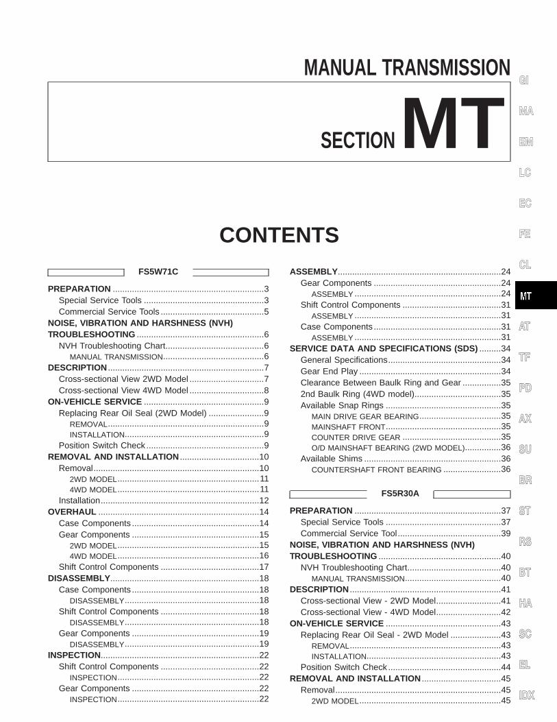
MANUAL TRANSMISSION SECTION MT CONTENTS FS5W71C PREPARATION ...............................................................3 Special Service Tools ..................................................3 Commercial Service Tools ...........................................5 NOISE, VIBRATION AND HARSHNESS (NVH) TROUBLESHOOTING .....................................................6 NVH Troubleshooting Chart.........................................6 MANUAL TRANSMISSION..........................................6 DESCRIPTION .................................................................7 Cross-sectional View 2WD Model ...............................7 Cross-sectional View 4WD Model ...............................8 ON-VEHICLE SERVICE ..................................................9 Replacing Rear Oil Seal (2WD Model) .......................9 REMOVAL.................................................................9 INSTALLATION..........................................................9 Position Switch Check .................................................9 REMOVAL AND INSTALLATION .................................10 Removal .....................................................................10 2WD MODEL ........................................................... 11 4WD MODEL ........................................................... 11 Installation ..................................................................12 OVERHAUL ...................................................................14 Case Components .....................................................14 Gear Components .....................................................15 2WD MODEL ...........................................................15 4WD MODEL ...........................................................16 Shift Control Components .........................................17 DISASSEMBLY..............................................................18 Case Components .....................................................18 DISASSEMBLY........................................................18 Shift Control Components .........................................18 DISASSEMBLY........................................................18 Gear Components .....................................................19 DISASSEMBLY........................................................19 INSPECTION..................................................................22 Shift Control Components .........................................22 INSPECTION...........................................................22 Gear Components .....................................................22 INSPECTION...........................................................22 ASSEMBLY....................................................................24 Gear Components .....................................................24 ASSEMBLY .............................................................24 Shift Control Components .........................................31 ASSEMBLY .............................................................31 Case Components .....................................................31 ASSEMBLY .............................................................31 SERVICE DATA AND SPECIFICATIONS (SDS) .........34 General Specifications ...............................................34 Gear End Play ...........................................................34 Clearance Between Baulk Ring and Gear ................35 2nd Baulk Ring (4WD model)....................................35 Available Snap Rings ................................................35 MAIN DRIVE GEAR BEARING..................................35 MAINSHAFT FRONT................................................35 COUNTER DRIVE GEAR .........................................35 O/D MAINSHAFT BEARING (2WD MODEL)...............36 Available Shims .........................................................36 COUNTERSHAFT FRONT BEARING ........................36 FS5R30A PREPARATION .............................................................37 Special Service Tools ................................................37 Commercial Service Tool ...........................................39 NOISE, VIBRATION AND HARSHNESS (NVH) TROUBLESHOOTING ...................................................40 NVH Troubleshooting Chart.......................................40 MANUAL TRANSMISSION........................................40 DESCRIPTION ...............................................................41 Cross-sectional View - 2WD Model ...........................41 Cross-sectional View - 4WD Model ...........................42 ON-VEHICLE SERVICE ................................................43 Replacing Rear Oil Seal - 2WD Model .....................43 REMOVAL...............................................................43 INSTALLATION........................................................43 Position Switch Check ...............................................44 REMOVAL AND INSTALLATION .................................45 Removal .....................................................................45 2WD MODEL ...........................................................45 GI MA EM LC EC FE CL AT TF PD AX SU BR ST RS BT HA SC EL IDX
Transcript of MANUAL TRANSMISSION -...
MANUAL TRANSMISSION
SECTIONMTCONTENTS
FS5W71C
PREPARATION ...............................................................3Special Service Tools ..................................................3Commercial Service Tools ...........................................5
NOISE, VIBRATION AND HARSHNESS (NVH)TROUBLESHOOTING .....................................................6
NVH Troubleshooting Chart.........................................6MANUAL TRANSMISSION..........................................6
DESCRIPTION .................................................................7Cross-sectional View 2WD Model ...............................7Cross-sectional View 4WD Model ...............................8
ON-VEHICLE SERVICE ..................................................9Replacing Rear Oil Seal (2WD Model) .......................9
REMOVAL.................................................................9INSTALLATION..........................................................9
Position Switch Check .................................................9REMOVAL AND INSTALLATION .................................10
Removal.....................................................................102WD MODEL...........................................................114WD MODEL...........................................................11
Installation..................................................................12OVERHAUL ...................................................................14
Case Components .....................................................14Gear Components .....................................................15
2WD MODEL...........................................................154WD MODEL...........................................................16
Shift Control Components .........................................17DISASSEMBLY ..............................................................18
Case Components .....................................................18DISASSEMBLY........................................................18
Shift Control Components .........................................18DISASSEMBLY........................................................18
Gear Components .....................................................19DISASSEMBLY........................................................19
INSPECTION..................................................................22Shift Control Components .........................................22
INSPECTION...........................................................22Gear Components .....................................................22
INSPECTION...........................................................22
ASSEMBLY ....................................................................24Gear Components .....................................................24
ASSEMBLY .............................................................24Shift Control Components .........................................31
ASSEMBLY .............................................................31Case Components .....................................................31
ASSEMBLY .............................................................31SERVICE DATA AND SPECIFICATIONS (SDS) .........34
General Specifications...............................................34Gear End Play ...........................................................34Clearance Between Baulk Ring and Gear ................352nd Baulk Ring (4WD model)....................................35Available Snap Rings ................................................35
MAIN DRIVE GEAR BEARING..................................35MAINSHAFT FRONT................................................35COUNTER DRIVE GEAR .........................................35O/D MAINSHAFT BEARING (2WD MODEL)...............36
Available Shims .........................................................36COUNTERSHAFT FRONT BEARING ........................36
FS5R30A
PREPARATION .............................................................37Special Service Tools ................................................37Commercial Service Tool...........................................39
NOISE, VIBRATION AND HARSHNESS (NVH)TROUBLESHOOTING ...................................................40
NVH Troubleshooting Chart.......................................40MANUAL TRANSMISSION........................................40
DESCRIPTION ...............................................................41Cross-sectional View - 2WD Model...........................41Cross-sectional View - 4WD Model...........................42
ON-VEHICLE SERVICE ................................................43Replacing Rear Oil Seal - 2WD Model .....................43
REMOVAL...............................................................43INSTALLATION........................................................43
Position Switch Check ...............................................44REMOVAL AND INSTALLATION .................................45
Removal.....................................................................452WD MODEL...........................................................45
GI
MA
EM
LC
EC
FE
CL
AT
TF
PD
AX
SU
BR
ST
RS
BT
HA
SC
EL
IDX
4WD MODEL...........................................................46Installation..................................................................47
OVERHAUL ...................................................................48Case Components .....................................................48Gear Components .....................................................49Shift Control Components (2/4WD models) ..............51
DISASSEMBLY ..............................................................52Case Components .....................................................52
DISASSEMBLY........................................................52Shift Control Components .........................................53
DISASSEMBLY........................................................53Gear Components .....................................................54
DISASSEMBLY........................................................54INSPECTION..................................................................58
Shift Control Components .........................................58INSPECTION...........................................................58
Gear Components .....................................................58INSPECTION...........................................................58
ASSEMBLY ....................................................................60Gear Components .....................................................60
ASSEMBLY .............................................................60Shift Control Components .........................................68
ASSEMBLY .............................................................68Case Components .....................................................69
ASSEMBLY .............................................................69SERVICE DATA AND SPECIFICATIONS (SDS) .........71
General Specifications...............................................71Gear End Play ...........................................................71Clearance Between Baulk Ring and Gear ................71
2ND AND 3RD BAULK RING....................................72Distance between Rear Surface of ReverseCone and Reverse Baulk Ring..................................72Available Snap Ring ..................................................72
MAIN DRIVE GEAR SNAP RING ..............................72MAINSHAFT FRONT SNAP RING.............................72COUNTER GEAR REAR SNAP RING .......................73
Available C-ring .........................................................73MAINSHAFT C-RING ...............................................73
Available Shim and Washer ......................................73TABLE FOR SELECTING PROPER COUNTERGEAR FRONT BEARING THRUST WASHER ............73REVERSE IDLER REAR THRUST WASHER .............73
CONTENTS (Cont’d)
MT-2
Special Service ToolsNEMT0050
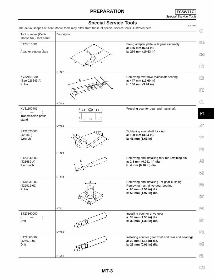
The actual shapes of Kent-Moore tools may differ from those of special service tools illustrated here.
Tool number (Kent-Moore No.) Tool name
Description
ST23810001( — )Adapter setting plate
NT407
Fixing adapter plate with gear assemblya: 166 mm (6.54 in)b: 270 mm (10.63 in)
KV32101330(See J26349-A)Puller
NT408
Removing overdrive mainshaft bearinga: 447 mm (17.60 in)b: 100 mm (3.94 in)
KV31100401( — )Transmission pressstand
NT068
Pressing counter gear and mainshaft
ST22520000(J26348)Wrench
NT409
Tightening mainshaft lock nuta: 100 mm (3.94 in)b: 41 mm (1.61 in)
ST23540000(J25689-A)Pin punch
NT442
Removing and installing fork rod retaining pina: 2.3 mm (0.091 in) dia.b: 4 mm (0.16 in) dia.
ST30031000(J22912-01)Puller
NT411
Removing and installing 1st gear bushingRemoving main drive gear bearinga: 90 mm (3.54 in) dia.b: 50 mm (1.97 in) dia.
ST23860000( — )Drift
NT065
Installing counter drive geara: 38 mm (1.50 in) dia.b: 33 mm (1.30 in) dia.
ST22360002(J25679-01)Drift
NT065
Installing counter gear front and rear end bearingsa: 29 mm (1.14 in) dia.b: 23 mm (0.91 in) dia.
GI
MA
EM
LC
EC
FE
CL
AT
TF
PD
AX
SU
BR
ST
RS
BT
HA
SC
EL
IDX
PREPARATION FS5W71CSpecial Service Tools
MT-3

Tool number (Kent-Moore No.) Tool name
Description
ST22350000(J25678-01)Drift
NT065
Installing O/D gear bushinga: 34 mm (1.34 in) dia.b: 28 mm (1.10 in) dia.
ST23800000(J25691-01)Drift
NT065
Installing front cover oil seala: 44 mm (1.73 in) dia.b: 31 mm (1.22 in) dia.
ST33400001(J26082)Drift
NT086
Installing rear oil seala: 60 mm (2.36 in) dia.b: 47 mm (1.85 in) dia.
ST33290001(J34286)Puller
NT414
Removing rear oil seala: 250 mm (9.84 in)b: 160 mm (6.30 in)
ST30720000(J25405)Drift
NT115
Installing mainshaft ball bearinga: 77 mm (3.03 in) dia.b: 55.5 mm (2.185 in) dia.
ST30613000(J25742-3)Drift
NT073
Installing main drive gear bearinga: 71.5 mm (2.815 in) dia.b: 47.5 mm (1.870 in) dia.
ST33200000(J26082)Drift
NT091
Installing counter rear bearinga: 60 mm (2.36 in) dia.b: 44.5 mm (1.752 in) dia.
PREPARATION FS5W71CSpecial Service Tools (Cont’d)
MT-4
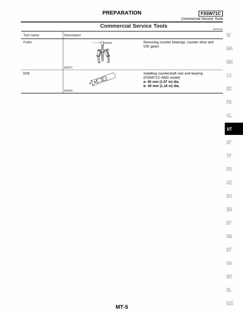
Commercial Service ToolsNEMT0051
Tool name Description
Puller
NT077
Removing counter bearings, counter drive andO/D gears
Drift
NT074
Installing countershaft rear end bearing(FS5W71C-4WD model)a: 40 mm (1.57 in) dia.b: 30 mm (1.18 in) dia.
GI
MA
EM
LC
EC
FE
CL
AT
TF
PD
AX
SU
BR
ST
RS
BT
HA
SC
EL
IDX
PREPARATION FS5W71CCommercial Service Tools
MT-5

NEMT0052
NVH Troubleshooting ChartNEMT0052S01
Use the chart below to help you find the cause of the symptom. The numbers indicate the order of the inspec-tion. If necessary, repair or replace these parts.
MANUAL TRANSMISSIONNEMT0052S0101
Reference page
Ref
erto
MA
-35
,(“
Che
ckin
gM
/TO
il”,
CH
AS
SIS
AN
DB
OD
YM
AIN
TE
NA
NC
E”)
.
MT-
14
MT-
14
MT-
17
MT-
17
MT-
15
MT-
15
MT-
15
MT-
15
SUSPECTED PARTS(Possible cause)
OIL
(Oil
leve
lis
low
.)
OIL
(Wro
ngoi
l.)
OIL
(Oil
leve
lis
high
.)
GA
SK
ET
(Dam
aged
)
OIL
SE
AL
(Wor
nor
dam
aged
)
CH
EC
KP
LUG
RE
TU
RN
SP
RIN
GA
ND
CH
EC
KB
ALL
(Wor
nor
dam
aged
)
SH
IFT
FO
RK
(Wor
n)
GE
AR
(Wor
nor
dam
aged
)
BE
AR
ING
(Wor
nor
dam
aged
)
BA
ULK
RIN
G(W
orn
orda
mag
ed)
INS
ER
TS
PR
ING
(Dam
aged
)
Symptom
Noise 1 2 3 3
Oil leakage 3 1 2 2
Hard to shift or will not shift 1 1 2 2
Jumps out of gear 1 2 2
NOISE, VIBRATION AND HARSHNESS (NVH)TROUBLESHOOTING FS5W71C
NVH Troubleshooting Chart
MT-6
NEMT0053
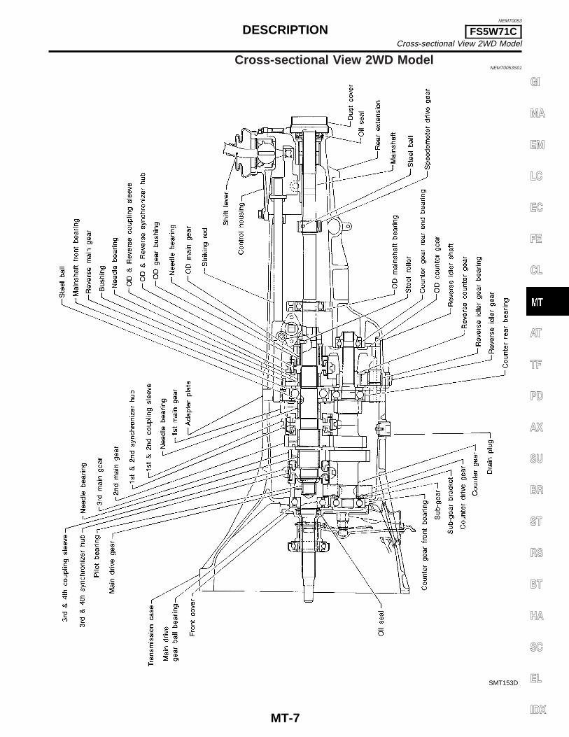
Cross-sectional View 2WD ModelNEMT0053S01
SMT153D
GI
MA
EM
LC
EC
FE
CL
AT
TF
PD
AX
SU
BR
ST
RS
BT
HA
SC
EL
IDX
DESCRIPTION FS5W71CCross-sectional View 2WD Model
MT-7

Cross-sectional View 4WD Model=NGMT0048S03
SMT154D
DESCRIPTION FS5W71CCross-sectional View 4WD Model
MT-8
AMT079
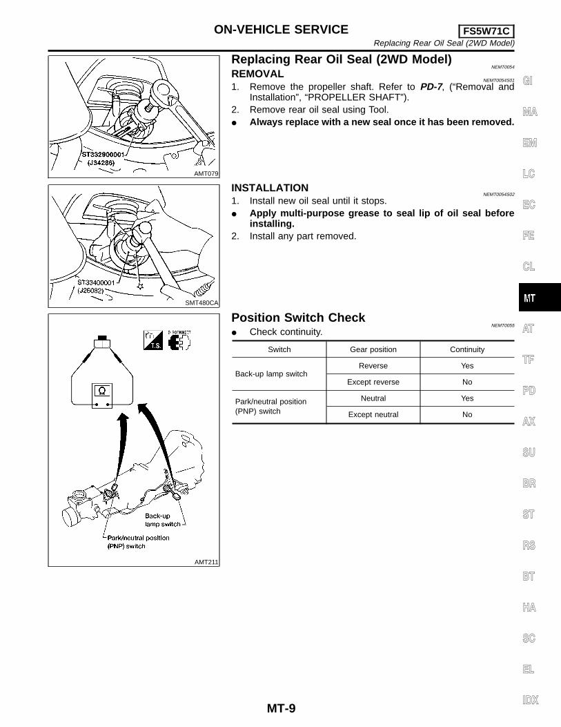
Replacing Rear Oil Seal (2WD Model)NEMT0054
REMOVALNEMT0054S01
1. Remove the propeller shaft. Refer to PD-7, (“Removal andInstallation”, “PROPELLER SHAFT”).
2. Remove rear oil seal using Tool.I Always replace with a new seal once it has been removed.
SMT480CA
INSTALLATIONNEMT0054S02
1. Install new oil seal until it stops.I Apply multi-purpose grease to seal lip of oil seal before
installing.2. Install any part removed.
AMT211
Position Switch CheckNEMT0055
I Check continuity.
Switch Gear position Continuity
Back-up lamp switchReverse Yes
Except reverse No
Park/neutral position(PNP) switch
Neutral Yes
Except neutral No
GI
MA
EM
LC
EC
FE
CL
AT
TF
PD
AX
SU
BR
ST
RS
BT
HA
SC
EL
IDX
ON-VEHICLE SERVICE FS5W71CReplacing Rear Oil Seal (2WD Model)
MT-9

NEMT0056
RemovalNEMT0056S01
AMT206
REMOVAL AND INSTALLATION FS5W71CRemoval
MT-10
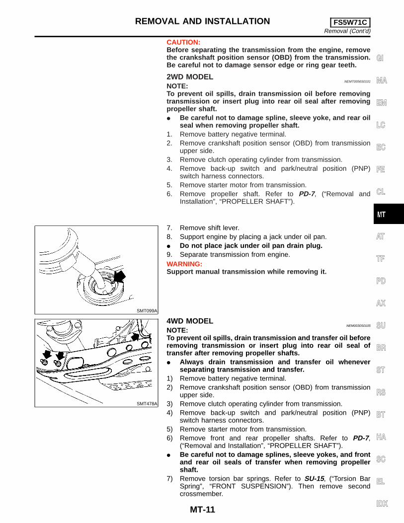
CAUTION:Before separating the transmission from the engine, removethe crankshaft position sensor (OBD) from the transmission.Be careful not to damage sensor edge or ring gear teeth.
2WD MODELNEMT0056S0101
NOTE:To prevent oil spills, drain transmission oil before removingtransmission or insert plug into rear oil seal after removingpropeller shaft.I Be careful not to damage spline, sleeve yoke, and rear oil
seal when removing propeller shaft.1. Remove battery negative terminal.2. Remove crankshaft position sensor (OBD) from transmission
upper side.3. Remove clutch operating cylinder from transmission.4. Remove back-up switch and park/neutral position (PNP)
switch harness connectors.5. Remove starter motor from transmission.6. Remove propeller shaft. Refer to PD-7, (“Removal and
Installation”, “PROPELLER SHAFT”).
SMT099A
7. Remove shift lever.8. Support engine by placing a jack under oil pan.I Do not place jack under oil pan drain plug.9. Separate transmission from engine.WARNING:Support manual transmission while removing it.
SMT478A
4WD MODELNEM0030S0105
NOTE:To prevent oil spills, drain transmission and transfer oil beforeremoving transmission or insert plug into rear oil seal oftransfer after removing propeller shafts.I Always drain transmission and transfer oil whenever
separating transmission and transfer.1) Remove battery negative terminal.2) Remove crankshaft position sensor (OBD) from transmission
upper side.3) Remove clutch operating cylinder from transmission.4) Remove back-up switch and park/neutral position (PNP)
switch harness connectors.5) Remove starter motor from transmission.6) Remove front and rear propeller shafts. Refer to PD-7,
(“Removal and Installation”, “PROPELLER SHAFT”).I Be careful not to damage splines, sleeve yokes, and front
and rear oil seals of transfer when removing propellershaft.
7) Remove torsion bar springs. Refer to SU-15, (“Torsion BarSpring”, “FRONT SUSPENSION”). Then remove secondcrossmember.
GI
MA
EM
LC
EC
FE
CL
AT
TF
PD
AX
SU
BR
ST
RS
BT
HA
SC
EL
IDX
REMOVAL AND INSTALLATION FS5W71CRemoval (Cont’d)
MT-11
SMT558A
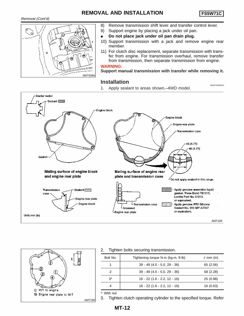
8) Remove transmission shift lever and transfer control lever.9) Support engine by placing a jack under oil pan.I Do not place jack under oil pan drain plug.10) Support transmission with a jack and remove engine rear
member.11) For clutch disc replacement, separate transmission with trans-
fer from engine. For transmission overhaul, remove transferfrom transmission, then separate transmission from engine.
WARNING:Support manual transmission with transfer while removing it.
InstallationNEMT0056S02
1. Apply sealant to areas shown,–4WD model.
AMT169
AMT190
2. Tighten bolts securing transmission.
Bolt No. Tightening torque N·m (kg-m, ft-lb) � mm (in)
1 39 - 49 (4.0 - 5.0, 29 - 36) 65 (2.56)
2 39 - 49 (4.0 - 5.0, 29 - 36) 58 (2.28)
3* 16 - 22 (1.6 - 2.2, 12 - 16) 25 (0.98)
4 16 - 22 (1.6 - 2.2, 12 - 16) 16 (0.63)
*: With nut
3. Tighten clutch operating cylinder to the specified torque. Refer
REMOVAL AND INSTALLATION FS5W71CRemoval (Cont’d)
MT-12
to CL-5, (“CLUTCH SYSTEM”).4. For transfer installation, refer to TF-10, (“Installation”,
“REMOVAL AND INSTALLATION”). GI
MA
EM
LC
EC
FE
CL
AT
TF
PD
AX
SU
BR
ST
RS
BT
HA
SC
EL
IDX
REMOVAL AND INSTALLATION FS5W71CInstallation (Cont’d)
MT-13
NEMT0057
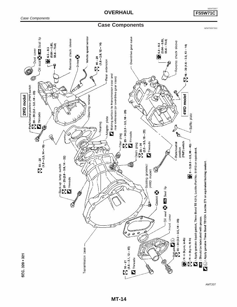
Case ComponentsNEMT0057S01
AMT207
OVERHAUL FS5W71CCase Components
MT-14
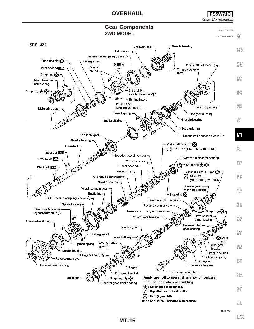
Gear ComponentsNEMT0057S02
2WD MODELNEMT0057S0201
AMT208
GI
MA
EM
LC
EC
FE
CL
AT
TF
PD
AX
SU
BR
ST
RS
BT
HA
SC
EL
IDX
OVERHAUL FS5W71CGear Components
MT-15

4WD MODELNEMT0057S0202
AMT209
OVERHAUL FS5W71CGear Components (Cont’d)
MT-16
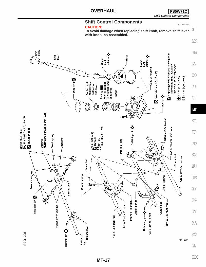
Shift Control ComponentsNEMT0057S03
CAUTION:To avoid damage when replacing shift knob, remove shift leverwith knob, as assembled.
AMT180
GI
MA
EM
LC
EC
FE
CL
AT
TF
PD
AX
SU
BR
ST
RS
BT
HA
SC
EL
IDX
OVERHAUL FS5W71CShift Control Components
MT-17

SMT161D
Case ComponentsDISASSEMBLY
NEMT0058
1. Remove rear extension.a. Remove control housing, check ball, return spring plugs, select
check plungers and return springs. Also remove reverse checkplug, check spring and check ball.
I Be careful not to lose check balls.
AMT132
b. Drive out striking lever retaining pin.c. Remove striking lever from striking rod.d. Remove rear extension by lightly tapping on it.
AMT131
2. Remove front cover, gasket, counter gear front bearing shimand main drive gear ball bearing snap ring.
3. Separate transmission case from adapter plate by lightly tap-ping on it.
SMT166D
4. Remove oil seal from front cover.I Be careful not to damage mating surface of front cover.
SMT545A
Shift Control ComponentsDISASSEMBLY
NEMT0059
1. Set up Tool on adapter plate.2. Remove striking rod from adapter plate.3. Remove check ball plugs, check springs, and check balls.
DISASSEMBLY FS5W71CCase Components
MT-18
SMT984
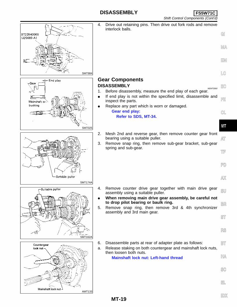
4. Drive out retaining pins. Then drive out fork rods and removeinterlock balls.
SMT025
Gear ComponentsDISASSEMBLY
NEMT0060
1. Before disassembly, measure the end play of each gear.I If end play is not within the specified limit, disassemble and
inspect the parts.I Replace any part which is worn or damaged.
Gear end play:Refer to SDS, MT-34.
SMT174A
2. Mesh 2nd and reverse gear, then remove counter gear frontbearing using a suitable puller.
3. Remove snap ring, then remove sub-gear bracket, sub-gearspring and sub-gear.
SMT162A
4. Remove counter drive gear together with main drive gearassembly using a suitable puller.
I When removing main drive gear assembly, be careful notto drop pilot bearing or baulk ring.
5. Remove snap ring, then remove 3rd & 4th synchronizerassembly and 3rd main gear.
AMT133
6. Disassemble parts at rear of adapter plate as follows:a. Release staking on both countergear and mainshaft lock nuts,
then loosen both nuts.Mainshaft lock nut: Left-hand thread
GI
MA
EM
LC
EC
FE
CL
AT
TF
PD
AX
SU
BR
ST
RS
BT
HA
SC
EL
IDX
DISASSEMBLY FS5W71CShift Control Components (Cont’d)
MT-19
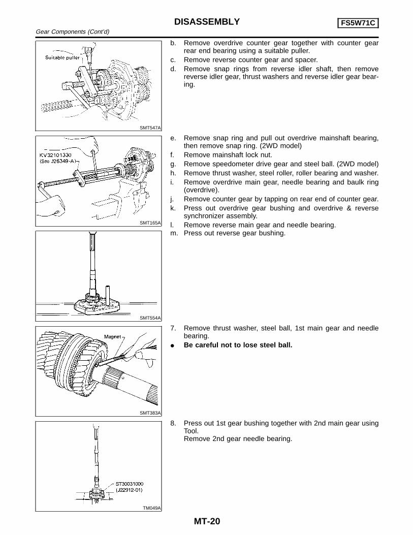
SMT547A
b. Remove overdrive counter gear together with counter gearrear end bearing using a suitable puller.
c. Remove reverse counter gear and spacer.d. Remove snap rings from reverse idler shaft, then remove
reverse idler gear, thrust washers and reverse idler gear bear-ing.
SMT165A
e. Remove snap ring and pull out overdrive mainshaft bearing,then remove snap ring. (2WD model)
f. Remove mainshaft lock nut.g. Remove speedometer drive gear and steel ball. (2WD model)h. Remove thrust washer, steel roller, roller bearing and washer.i. Remove overdrive main gear, needle bearing and baulk ring
(overdrive).j. Remove counter gear by tapping on rear end of counter gear.k. Press out overdrive gear bushing and overdrive & reverse
synchronizer assembly.l. Remove reverse main gear and needle bearing.
SMT554A
m. Press out reverse gear bushing.
SMT383A
7. Remove thrust washer, steel ball, 1st main gear and needlebearing.
I Be careful not to lose steel ball.
TM049A
8. Press out 1st gear bushing together with 2nd main gear usingTool.Remove 2nd gear needle bearing.
DISASSEMBLY FS5W71CGear Components (Cont’d)
MT-20
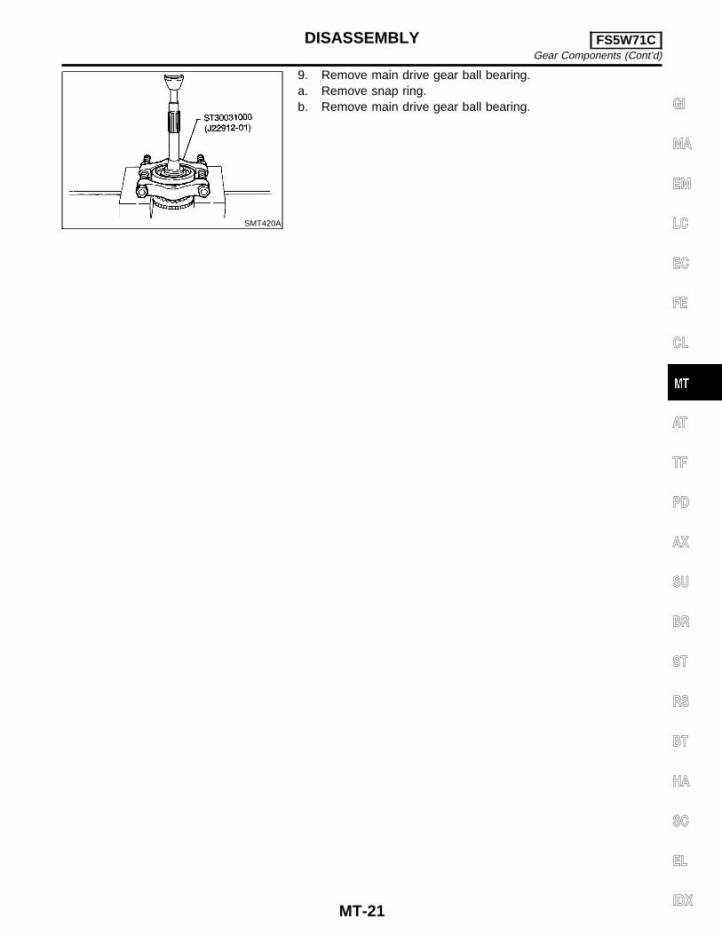
SMT420A
9. Remove main drive gear ball bearing.a. Remove snap ring.b. Remove main drive gear ball bearing. GI
MA
EM
LC
EC
FE
CL
AT
TF
PD
AX
SU
BR
ST
RS
BT
HA
SC
EL
IDX
DISASSEMBLY FS5W71CGear Components (Cont’d)
MT-21
SMT075C
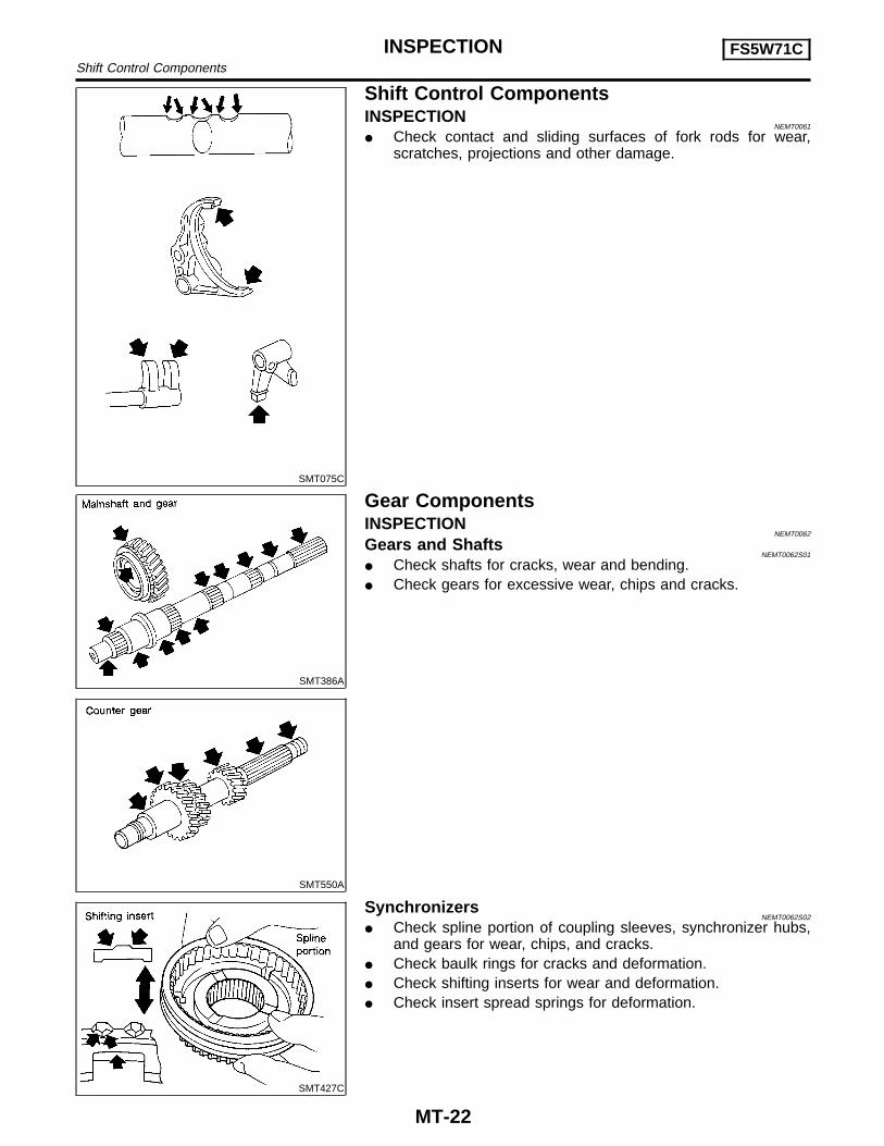
Shift Control ComponentsINSPECTION
NEMT0061
I Check contact and sliding surfaces of fork rods for wear,scratches, projections and other damage.
SMT386A
SMT550A
Gear ComponentsINSPECTION
NEMT0062
Gears and ShaftsNEMT0062S01
I Check shafts for cracks, wear and bending.I Check gears for excessive wear, chips and cracks.
SMT427C
SynchronizersNEMT0062S02
I Check spline portion of coupling sleeves, synchronizer hubs,and gears for wear, chips, and cracks.
I Check baulk rings for cracks and deformation.I Check shifting inserts for wear and deformation.I Check insert spread springs for deformation.
INSPECTION FS5W71CShift Control Components
MT-22
SMT140
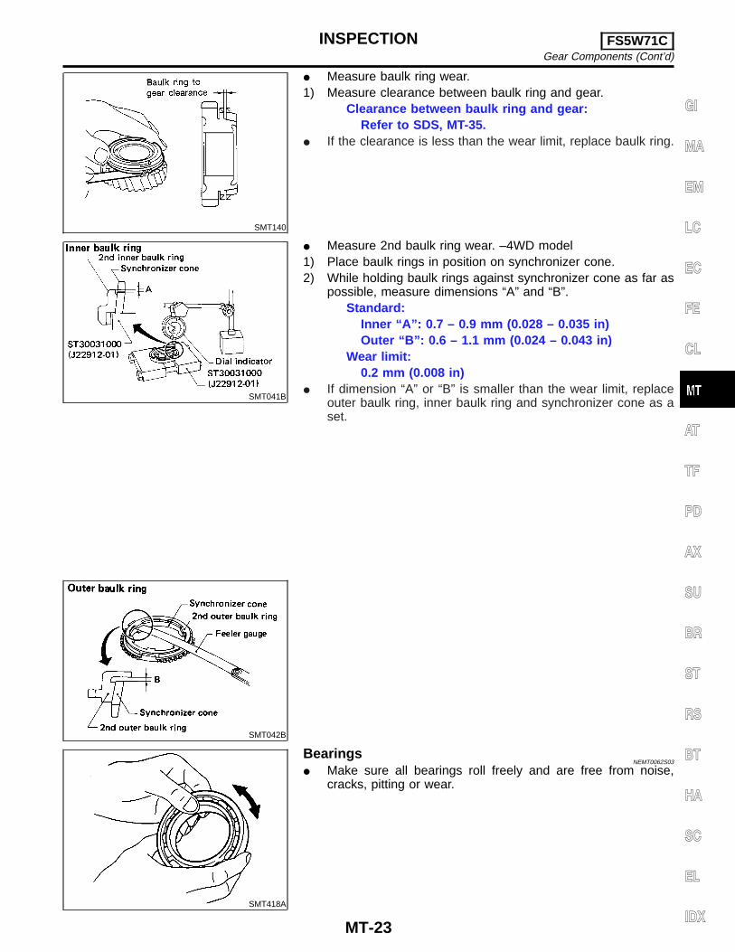
I Measure baulk ring wear.1) Measure clearance between baulk ring and gear.
Clearance between baulk ring and gear:Refer to SDS, MT-35.
I If the clearance is less than the wear limit, replace baulk ring.
SMT041B
I Measure 2nd baulk ring wear. –4WD model1) Place baulk rings in position on synchronizer cone.2) While holding baulk rings against synchronizer cone as far as
possible, measure dimensions “A” and “B”.Standard:
Inner “A”: 0.7 – 0.9 mm (0.028 – 0.035 in)Outer “B”: 0.6 – 1.1 mm (0.024 – 0.043 in)
Wear limit:0.2 mm (0.008 in)
I If dimension “A” or “B” is smaller than the wear limit, replaceouter baulk ring, inner baulk ring and synchronizer cone as aset.
SMT042B
SMT418A
BearingsNEMT0062S03
I Make sure all bearings roll freely and are free from noise,cracks, pitting or wear.
GI
MA
EM
LC
EC
FE
CL
AT
TF
PD
AX
SU
BR
ST
RS
BT
HA
SC
EL
IDX
INSPECTION FS5W71CGear Components (Cont’d)
MT-23
Gear ComponentsASSEMBLY
NEMT0063
AMT195
SMT778C
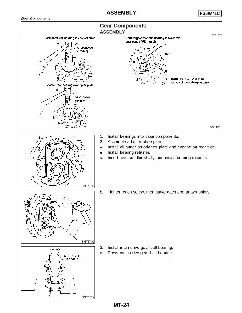
1. Install bearings into case components.2. Assemble adapter plate parts.I Install oil gutter on adapter plate and expand on rear side.I Install bearing retainer.a. Insert reverse idler shaft, then install bearing retainer.
SMT674C
b. Tighten each screw, then stake each one at two points.
SMT425A
3. Install main drive gear ball bearing.a. Press main drive gear ball bearing.
ASSEMBLY FS5W71CGear Components
MT-24
SMT170D
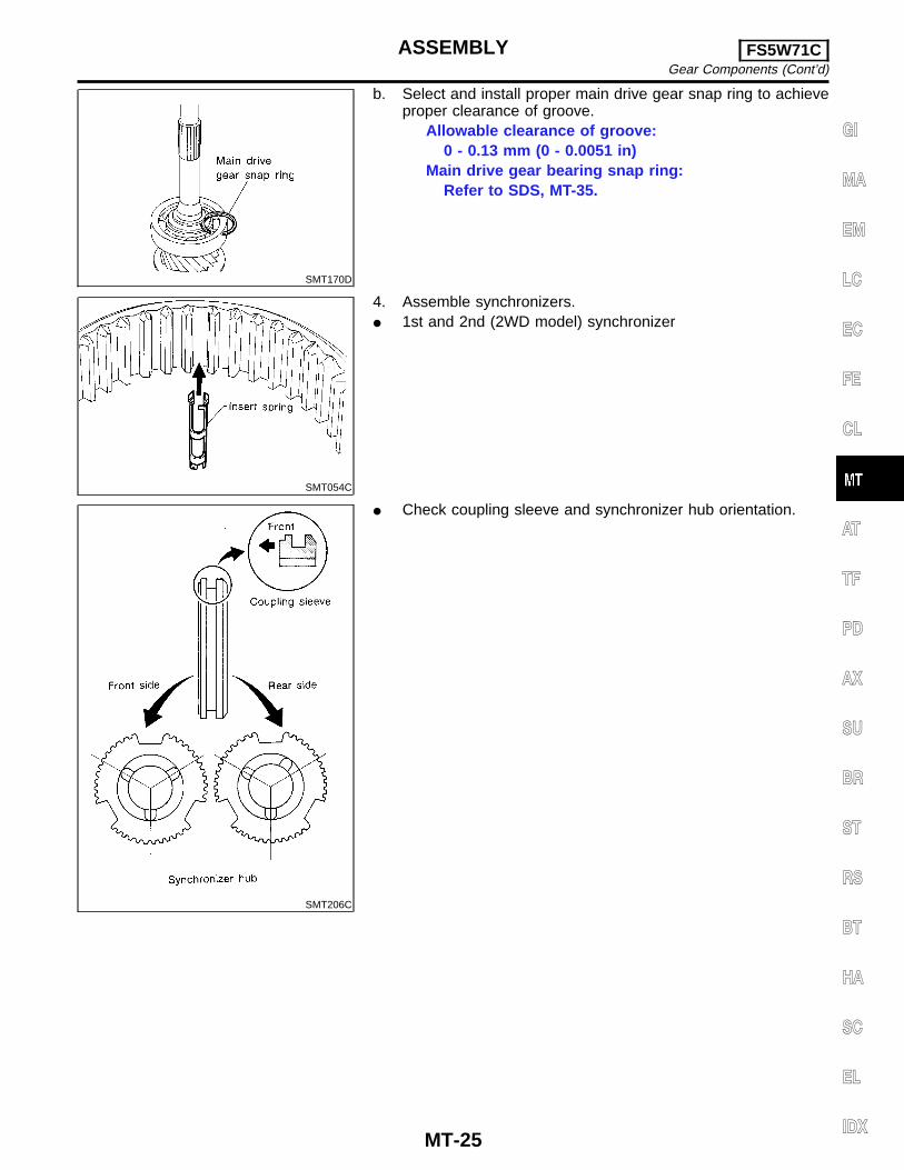
b. Select and install proper main drive gear snap ring to achieveproper clearance of groove.
Allowable clearance of groove:0 - 0.13 mm (0 - 0.0051 in)
Main drive gear bearing snap ring:Refer to SDS, MT-35.
SMT054C
4. Assemble synchronizers.I 1st and 2nd (2WD model) synchronizer
SMT206C
I Check coupling sleeve and synchronizer hub orientation.
GI
MA
EM
LC
EC
FE
CL
AT
TF
PD
AX
SU
BR
ST
RS
BT
HA
SC
EL
IDX
ASSEMBLY FS5W71CGear Components (Cont’d)
MT-25
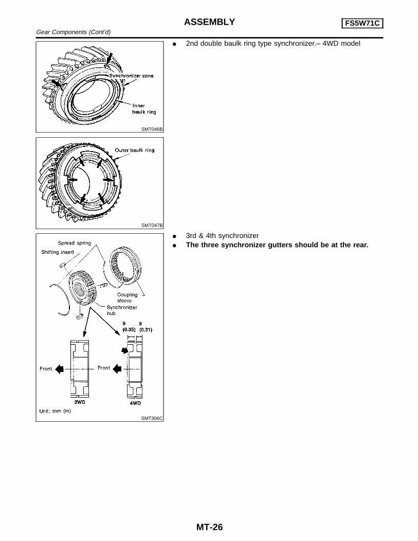
SMT046B
SMT047B
I 2nd double baulk ring type synchronizer.– 4WD model
SMT306C
I 3rd & 4th synchronizerI The three synchronizer gutters should be at the rear.
ASSEMBLY FS5W71CGear Components (Cont’d)
MT-26
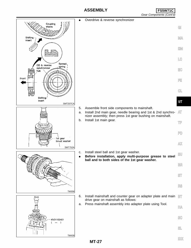
SMT207CA
I Overdrive & reverse synchronizer
SMT752A
5. Assemble front side components to mainshaft.a. Install 2nd main gear, needle bearing and 1st & 2nd synchro-
nizer assembly; then press 1st gear bushing on mainshaft.b. Install 1st main gear.
TM358
c. Install steel ball and 1st gear washer.I Before installation, apply multi-purpose grease to steel
ball and to both sides of the 1st gear washer.
TM439
6. Install mainshaft and counter gear on adapter plate and maindrive gear on mainshaft as follows:
a. Press mainshaft assembly into adapter plate using Tool.
GI
MA
EM
LC
EC
FE
CL
AT
TF
PD
AX
SU
BR
ST
RS
BT
HA
SC
EL
IDX
ASSEMBLY FS5W71CGear Components (Cont’d)
MT-27
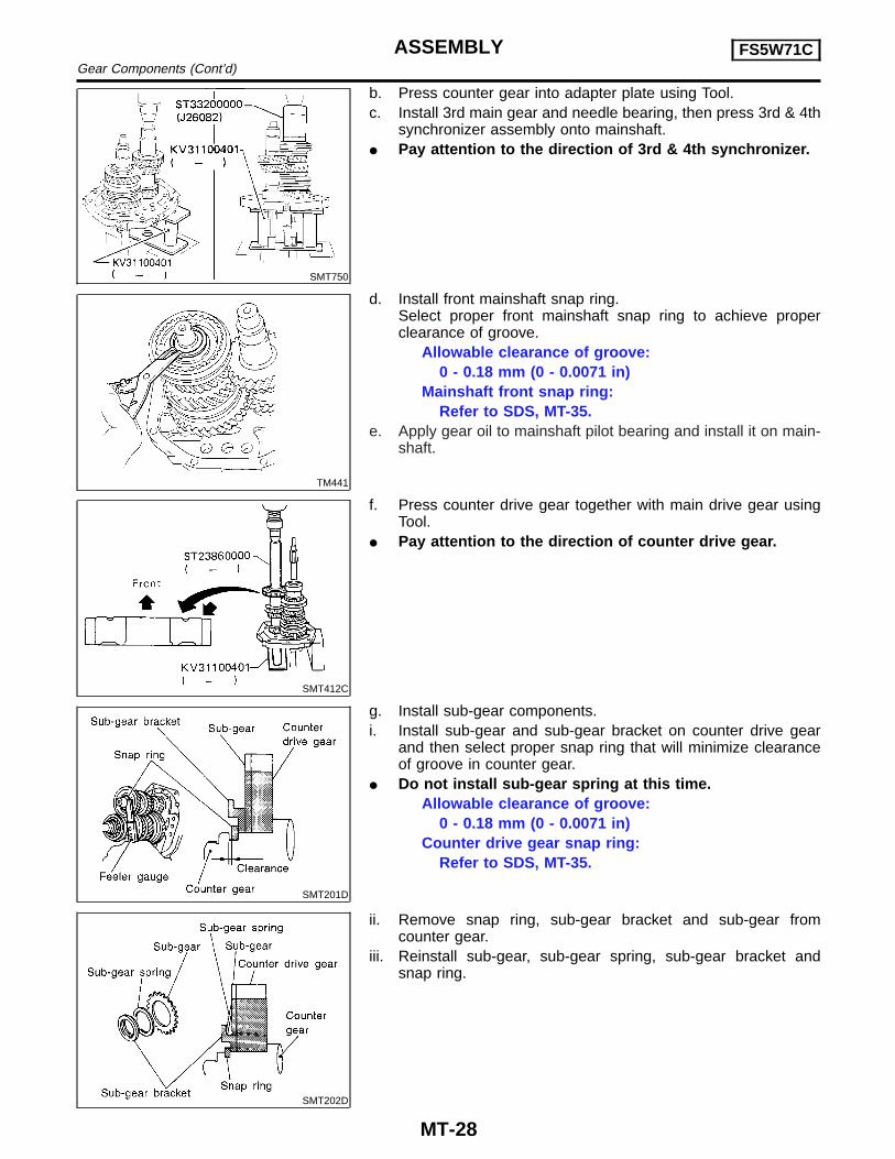
SMT750
b. Press counter gear into adapter plate using Tool.c. Install 3rd main gear and needle bearing, then press 3rd & 4th
synchronizer assembly onto mainshaft.I Pay attention to the direction of 3rd & 4th synchronizer.
TM441
d. Install front mainshaft snap ring.Select proper front mainshaft snap ring to achieve properclearance of groove.
Allowable clearance of groove:0 - 0.18 mm (0 - 0.0071 in)
Mainshaft front snap ring:Refer to SDS, MT-35.
e. Apply gear oil to mainshaft pilot bearing and install it on main-shaft.
SMT412C
f. Press counter drive gear together with main drive gear usingTool.
I Pay attention to the direction of counter drive gear.
SMT201D
g. Install sub-gear components.i. Install sub-gear and sub-gear bracket on counter drive gear
and then select proper snap ring that will minimize clearanceof groove in counter gear.
I Do not install sub-gear spring at this time.Allowable clearance of groove:
0 - 0.18 mm (0 - 0.0071 in)Counter drive gear snap ring:
Refer to SDS, MT-35.
SMT202D
ii. Remove snap ring, sub-gear bracket and sub-gear fromcounter gear.
iii. Reinstall sub-gear, sub-gear spring, sub-gear bracket andsnap ring.
ASSEMBLY FS5W71CGear Components (Cont’d)
MT-28
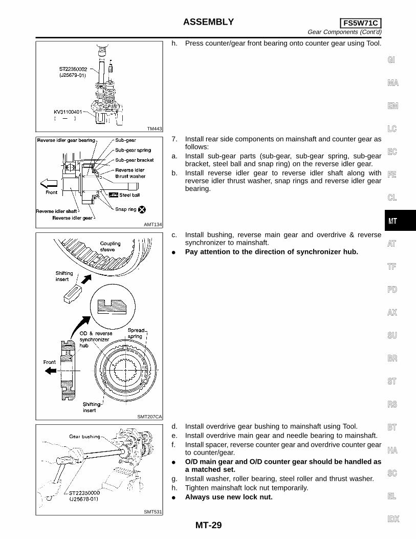
TM443
h. Press counter/gear front bearing onto counter gear using Tool.
AMT134
7. Install rear side components on mainshaft and counter gear asfollows:
a. Install sub-gear parts (sub-gear, sub-gear spring, sub-gearbracket, steel ball and snap ring) on the reverse idler gear.
b. Install reverse idler gear to reverse idler shaft along withreverse idler thrust washer, snap rings and reverse idler gearbearing.
SMT207CA
c. Install bushing, reverse main gear and overdrive & reversesynchronizer to mainshaft.
I Pay attention to the direction of synchronizer hub.
SMT531
d. Install overdrive gear bushing to mainshaft using Tool.e. Install overdrive main gear and needle bearing to mainshaft.f. Install spacer, reverse counter gear and overdrive counter gear
to counter/gear.I O/D main gear and O/D counter gear should be handled as
a matched set.g. Install washer, roller bearing, steel roller and thrust washer.h. Tighten mainshaft lock nut temporarily.I Always use new lock nut.
GI
MA
EM
LC
EC
FE
CL
AT
TF
PD
AX
SU
BR
ST
RS
BT
HA
SC
EL
IDX
ASSEMBLY FS5W71CGear Components (Cont’d)
MT-29
SMT043
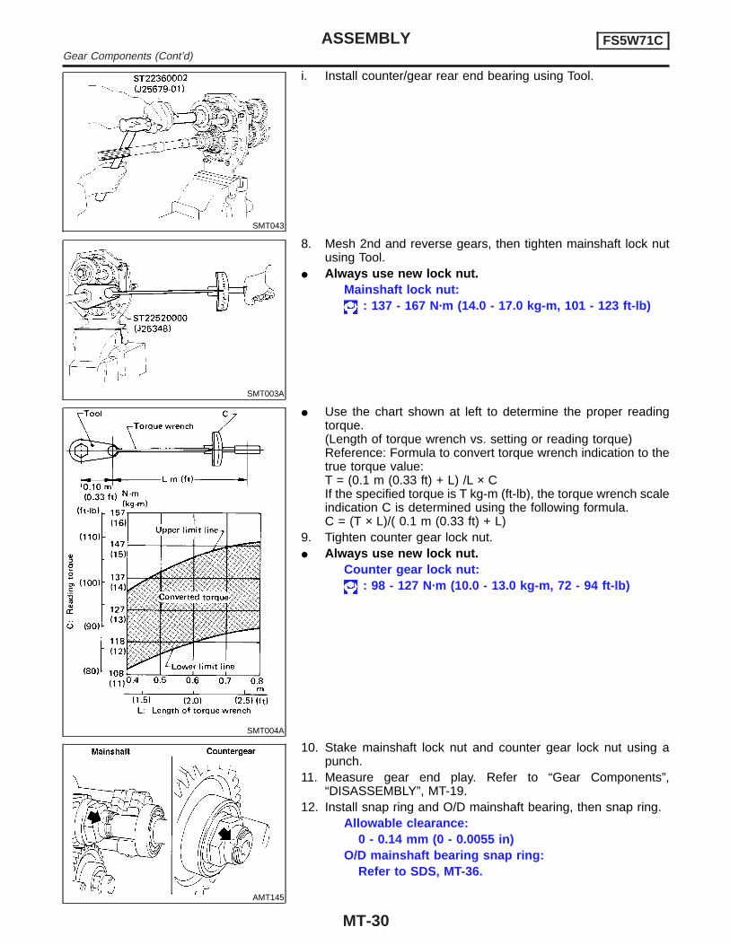
i. Install counter/gear rear end bearing using Tool.
SMT003A
8. Mesh 2nd and reverse gears, then tighten mainshaft lock nutusing Tool.
I Always use new lock nut.Mainshaft lock nut:
: 137 - 167 N·m (14.0 - 17.0 kg-m, 101 - 123 ft-lb)
SMT004A
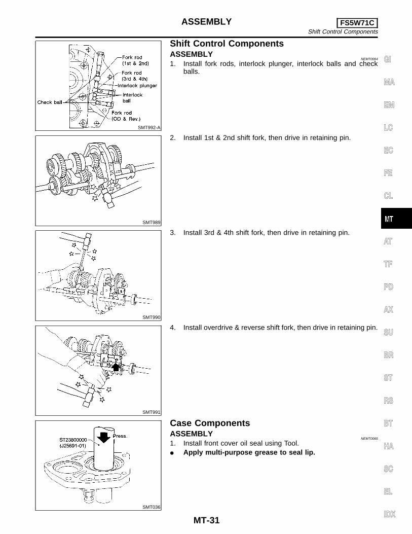
I Use the chart shown at left to determine the proper readingtorque.(Length of torque wrench vs. setting or reading torque)Reference: Formula to convert torque wrench indication to thetrue torque value:T = (0.1 m (0.33 ft) + L) /L × CIf the specified torque is T kg-m (ft-lb), the torque wrench scaleindication C is determined using the following formula.C = (T × L)/( 0.1 m (0.33 ft) + L)
9. Tighten counter gear lock nut.I Always use new lock nut.
Counter gear lock nut:: 98 - 127 N·m (10.0 - 13.0 kg-m, 72 - 94 ft-lb)
AMT145
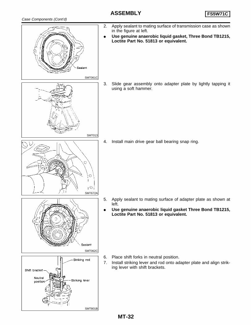
10. Stake mainshaft lock nut and counter gear lock nut using apunch.
11. Measure gear end play. Refer to “Gear Components”,“DISASSEMBLY”, MT-19.
12. Install snap ring and O/D mainshaft bearing, then snap ring.Allowable clearance:
0 - 0.14 mm (0 - 0.0055 in)O/D mainshaft bearing snap ring:
Refer to SDS, MT-36.
ASSEMBLY FS5W71CGear Components (Cont’d)
MT-30
SMT992-A
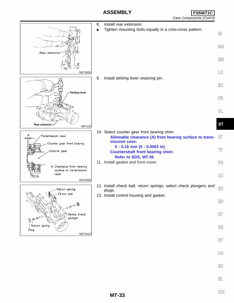
Shift Control ComponentsASSEMBLY
NEMT0064
1. Install fork rods, interlock plunger, interlock balls and checkballs.
SMT989
2. Install 1st & 2nd shift fork, then drive in retaining pin.
SMT990
3. Install 3rd & 4th shift fork, then drive in retaining pin.
SMT991
4. Install overdrive & reverse shift fork, then drive in retaining pin.
SMT036
Case ComponentsASSEMBLY
NEMT0065
1. Install front cover oil seal using Tool.I Apply multi-purpose grease to seal lip.
GI
MA
EM
LC
EC
FE
CL
AT
TF
PD
AX
SU
BR
ST
RS
BT
HA
SC
EL
IDX
ASSEMBLY FS5W71CShift Control Components
MT-31
SMT061C
2. Apply sealant to mating surface of transmission case as shownin the figure at left.
I Use genuine anaerobic liquid gasket, Three Bond TB1215,Loctite Part No. 51813 or equivalent.
SMT013
3. Slide gear assembly onto adapter plate by lightly tapping itusing a soft hammer.
SMT672A
4. Install main drive gear ball bearing snap ring.
SMT062C
5. Apply sealant to mating surface of adapter plate as shown atleft.
I Use genuine anaerobic liquid gasket Three Bond TB1215,Loctite Part No. 51813 or equivalent.
SMT801B
6. Place shift forks in neutral position.7. Install striking lever and rod onto adapter plate and align strik-
ing lever with shift brackets.
ASSEMBLY FS5W71CCase Components (Cont’d)
MT-32
SMT180D
8. Install rear extension.I Tighten mounting bolts equally in a criss-cross pattern.
AMT132
9. Install striking lever retaining pin.
SMT205D
10. Select counter gear front bearing shim.Allowable clearance (A) from bearing surface to trans-mission case:
0 - 0.16 mm (0 - 0.0063 in)Countershaft front bearing shim:
Refer to SDS, MT-36.11. Install gasket and front cover.
SMT161D
12. Install check ball, return springs, select check plungers andplugs.
13. Install control housing and gasket.
GI
MA
EM
LC
EC
FE
CL
AT
TF
PD
AX
SU
BR
ST
RS
BT
HA
SC
EL
IDX
ASSEMBLY FS5W71CCase Components (Cont’d)
MT-33
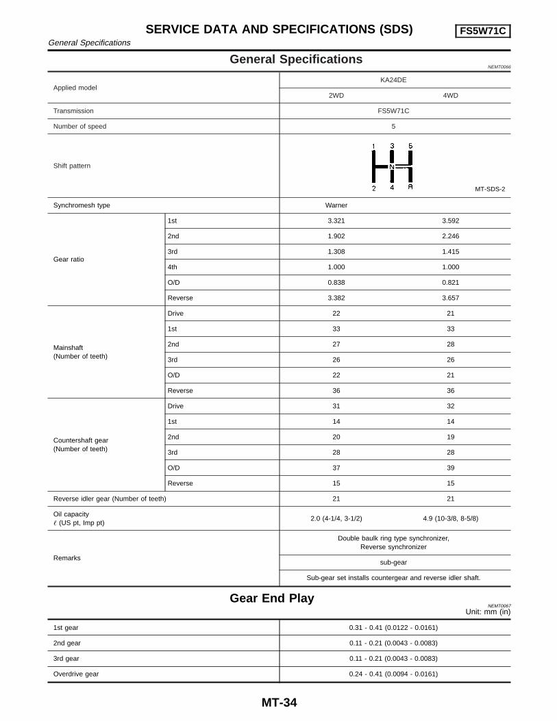
General SpecificationsNEMT0066
Applied modelKA24DE
2WD 4WD
Transmission FS5W71C
Number of speed 5
Shift pattern
MT-SDS-2
Synchromesh type Warner
Gear ratio
1st 3.321 3.592
2nd 1.902 2.246
3rd 1.308 1.415
4th 1.000 1.000
O/D 0.838 0.821
Reverse 3.382 3.657
Mainshaft(Number of teeth)
Drive 22 21
1st 33 33
2nd 27 28
3rd 26 26
O/D 22 21
Reverse 36 36
Countershaft gear(Number of teeth)
Drive 31 32
1st 14 14
2nd 20 19
3rd 28 28
O/D 37 39
Reverse 15 15
Reverse idler gear (Number of teeth) 21 21
Oil capacity� (US pt, Imp pt)
2.0 (4-1/4, 3-1/2) 4.9 (10-3/8, 8-5/8)
Remarks
Double baulk ring type synchronizer,Reverse synchronizer
sub-gear
Sub-gear set installs countergear and reverse idler shaft.
Gear End PlayNEMT0067
Unit: mm (in)
1st gear 0.31 - 0.41 (0.0122 - 0.0161)
2nd gear 0.11 - 0.21 (0.0043 - 0.0083)
3rd gear 0.11 - 0.21 (0.0043 - 0.0083)
Overdrive gear 0.24 - 0.41 (0.0094 - 0.0161)
SERVICE DATA AND SPECIFICATIONS (SDS) FS5W71CGeneral Specifications
MT-34
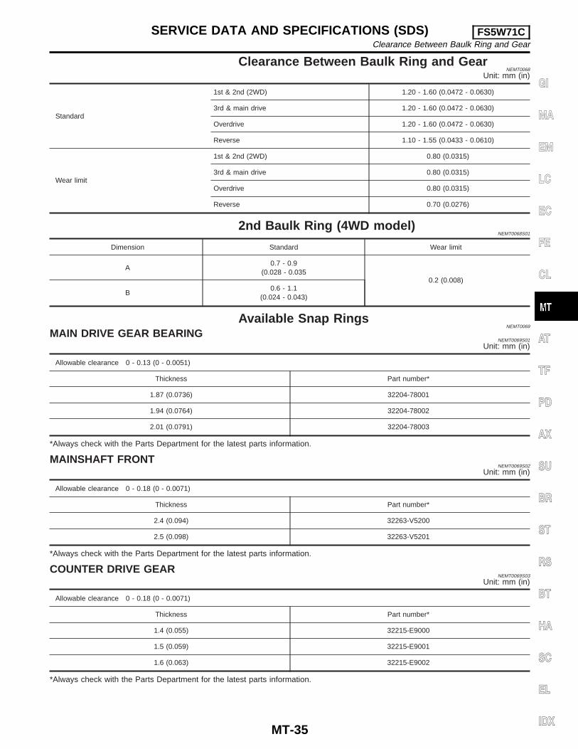
Clearance Between Baulk Ring and GearNEMT0068
Unit: mm (in)
Standard
1st & 2nd (2WD) 1.20 - 1.60 (0.0472 - 0.0630)
3rd & main drive 1.20 - 1.60 (0.0472 - 0.0630)
Overdrive 1.20 - 1.60 (0.0472 - 0.0630)
Reverse 1.10 - 1.55 (0.0433 - 0.0610)
Wear limit
1st & 2nd (2WD) 0.80 (0.0315)
3rd & main drive 0.80 (0.0315)
Overdrive 0.80 (0.0315)
Reverse 0.70 (0.0276)
2nd Baulk Ring (4WD model)NEMT0068S01
Dimension Standard Wear limit
A0.7 - 0.9
(0.028 - 0.0350.2 (0.008)
B0.6 - 1.1
(0.024 - 0.043)
Available Snap RingsNEMT0069
MAIN DRIVE GEAR BEARINGNEMT0069S01
Unit: mm (in)
Allowable clearance 0 - 0.13 (0 - 0.0051)
Thickness Part number*
1.87 (0.0736) 32204-78001
1.94 (0.0764) 32204-78002
2.01 (0.0791) 32204-78003
*Always check with the Parts Department for the latest parts information.
MAINSHAFT FRONTNEMT0069S02
Unit: mm (in)
Allowable clearance 0 - 0.18 (0 - 0.0071)
Thickness Part number*
2.4 (0.094) 32263-V5200
2.5 (0.098) 32263-V5201
*Always check with the Parts Department for the latest parts information.
COUNTER DRIVE GEARNEMT0069S03
Unit: mm (in)
Allowable clearance 0 - 0.18 (0 - 0.0071)
Thickness Part number*
1.4 (0.055) 32215-E9000
1.5 (0.059) 32215-E9001
1.6 (0.063) 32215-E9002
*Always check with the Parts Department for the latest parts information.
GI
MA
EM
LC
EC
FE
CL
AT
TF
PD
AX
SU
BR
ST
RS
BT
HA
SC
EL
IDX
SERVICE DATA AND SPECIFICATIONS (SDS) FS5W71CClearance Between Baulk Ring and Gear
MT-35

O/D MAINSHAFT BEARING (2WD MODEL)NEMT0069S04
Unit: mm (in)
Allowable clearance 0 - 0.14 (0 - 0.0055)
Thickness Part number*
1.1 (0.043) 32228-20100
1.2 (0.047) 32228-20101
1.3 (0.051) 32228-20102
1.4 (0.055) 32228-20103
*Always check with the Parts Department for the latest parts information.
Available ShimsNEMT0070
COUNTERSHAFT FRONT BEARINGNEMT0070S01
Unit: mm (in)
SMT205D
“A” Thickness of shim Part number*
4.52 - 4.71 (0.1780 - 0.1854) Not necessary
4.42 - 4.51 (0.1740 - 0.1776) 0.1 (0.004) 32218-V5000
4.32 - 4.41 (0.1701 - 0.1736) 0.2 (0.008) 32218-V5001
4.22 - 4.31 (0.1661 - 0.1697) 0.3 (0.012) 32218-V5002
4.12 - 4.21 (0.1622 - 0.1657) 0.4 (0.016) 32218-V5003
4.02 - 4.11 (0.1583 - 0.1618) 0.5 (0.020) 32218-V5004
3.92 - 4.01 (0.1543 - 0.1579) 0.6 (0.024) 32218-V5005
*Always check with the Parts Department for the latest parts information.
SERVICE DATA AND SPECIFICATIONS (SDS) FS5W71CAvailable Snap Rings (Cont’d)
MT-36
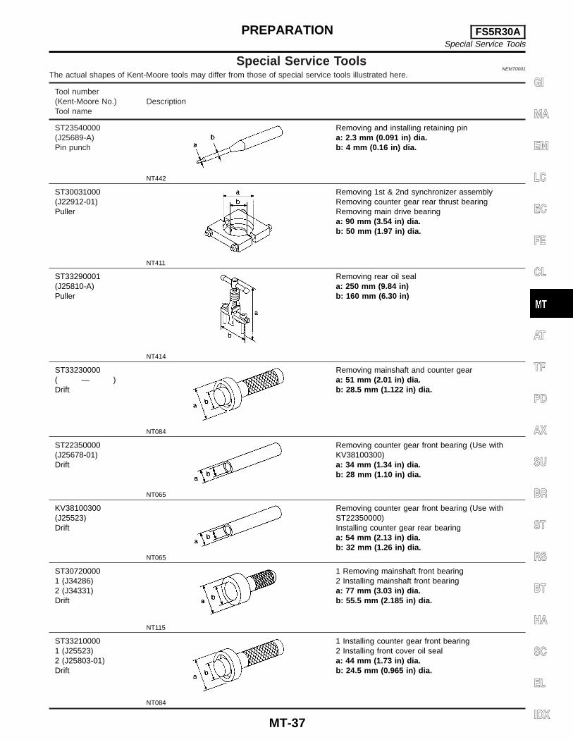
Special Service ToolsNEMT0001
The actual shapes of Kent-Moore tools may differ from those of special service tools illustrated here.
Tool number(Kent-Moore No.)Tool name
Description
ST23540000(J25689-A)Pin punch
NT442
Removing and installing retaining pina: 2.3 mm (0.091 in) dia.b: 4 mm (0.16 in) dia.
ST30031000(J22912-01)Puller
NT411
Removing 1st & 2nd synchronizer assemblyRemoving counter gear rear thrust bearingRemoving main drive bearinga: 90 mm (3.54 in) dia.b: 50 mm (1.97 in) dia.
ST33290001(J25810-A)Puller
NT414
Removing rear oil seala: 250 mm (9.84 in)b: 160 mm (6.30 in)
ST33230000( — )Drift
NT084
Removing mainshaft and counter geara: 51 mm (2.01 in) dia.b: 28.5 mm (1.122 in) dia.
ST22350000(J25678-01)Drift
NT065
Removing counter gear front bearing (Use withKV38100300)a: 34 mm (1.34 in) dia.b: 28 mm (1.10 in) dia.
KV38100300(J25523)Drift
NT065
Removing counter gear front bearing (Use withST22350000)Installing counter gear rear bearinga: 54 mm (2.13 in) dia.b: 32 mm (1.26 in) dia.
ST307200001 (J34286)2 (J34331)Drift
NT115
1 Removing mainshaft front bearing2 Installing mainshaft front bearinga: 77 mm (3.03 in) dia.b: 55.5 mm (2.185 in) dia.
ST332100001 (J25523)2 (J25803-01)Drift
NT084
1 Installing counter gear front bearing2 Installing front cover oil seala: 44 mm (1.73 in) dia.b: 24.5 mm (0.965 in) dia.
GI
MA
EM
LC
EC
FE
CL
AT
TF
PD
AX
SU
BR
ST
RS
BT
HA
SC
EL
IDX
PREPARATION FS5R30ASpecial Service Tools
MT-37
Tool number(Kent-Moore No.)Tool name
Description
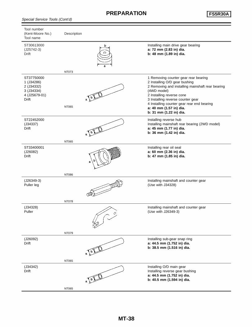
ST30613000(J25742-3)Drift
NT073
Installing main drive gear bearinga: 72 mm (2.83 in) dia.b: 48 mm (1.89 in) dia.
ST377500001 (J34286)2 (J34332)3 (J34334)4 (J25679-01)Drift
NT065
1 Removing counter gear rear bearing2 Installing O/D gear bushing2 Removing and installing mainshaft rear bearing(4WD model)2 Installing reverse cone3 Installing reverse counter gear4 Installing counter gear rear end bearinga: 40 mm (1.57 in) dia.b: 31 mm (1.22 in) dia.
ST22452000(J34337)Drift
NT065
Installing reverse hubInstalling mainshaft rear bearing (2WD model)a: 45 mm (1.77 in) dia.b: 36 mm (1.42 in) dia.
ST33400001(J26082)Drift
NT086
Installing rear oil seala: 60 mm (2.36 in) dia.b: 47 mm (1.85 in) dia.
(J26349-3)Puller leg
NT078
Installing mainshaft and counter gear(Use with J34328)
(J34328)Puller
NT079
Installing mainshaft and counter gear(Use with J26349-3)
(J26092)Drift
NT065
Installing sub-gear snap ringa: 44.5 mm (1.752 in) dia.b: 38.5 mm (1.516 in) dia.
(J34342)Drift
NT065
Installing O/D main gearInstalling reverse gear bushinga: 44.5 mm (1.752 in) dia.b: 40.5 mm (1.594 in) dia.
PREPARATION FS5R30ASpecial Service Tools (Cont’d)
MT-38
Tool number(Kent-Moore No.)Tool name
Description
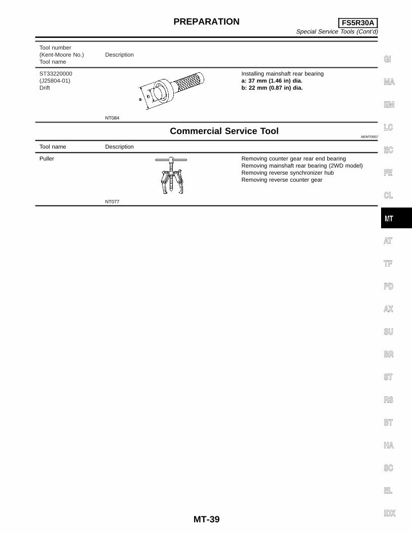
ST33220000(J25804-01)Drift
NT084
Installing mainshaft rear bearinga: 37 mm (1.46 in) dia.b: 22 mm (0.87 in) dia.
Commercial Service ToolNEMT0002
Tool name Description
Puller
NT077
Removing counter gear rear end bearingRemoving mainshaft rear bearing (2WD model)Removing reverse synchronizer hubRemoving reverse counter gear
GI
MA
EM
LC
EC
FE
CL
AT
TF
PD
AX
SU
BR
ST
RS
BT
HA
SC
EL
IDX
PREPARATION FS5R30ASpecial Service Tools (Cont’d)
MT-39

NEMT0023
NVH Troubleshooting ChartNEMT0023S01
Use the chart below to help you find the cause of the problem. The numbers indicate the order of the inspec-tion. If necessary, repair or replace these parts.
MANUAL TRANSMISSIONNEMT0023S0101
Reference page
Ref
erto
MA
-35
(“C
heck
ing
M/T
Oil”
,“C
HA
SS
ISA
ND
BO
DY
MA
INT
EN
AN
CE
”).
MT-
48
MT-
48
MT-
51
MT-
51
MT-
51
MT-
49
MT-
49
MT-
49
MT-
49
SUSPECTED PARTS(Possible cause)
OIL
(Lev
ello
w)
OIL
(Wro
ng)
OIL
(Lev
elto
ohi
gh)
GA
SK
ET
(Dam
aged
)
OIL
SE
AL
(Wor
nor
dam
aged
)
O-R
ING
(Wor
nor
dam
aged
)
CH
EC
KP
LUG
RE
TU
RN
SP
RIN
GA
ND
CH
EC
KB
ALL
(Wor
nor
dam
aged
)
SH
IFT
FO
RK
(Wor
n)
GE
AR
(Wor
nor
dam
aged
)
BE
AR
ING
(Wor
nor
dam
aged
)
BA
ULK
RIN
G(W
orn
orda
mag
ed)
INS
ER
TS
PR
ING
(Dam
aged
)
Symptom
Noise 1 2 3 3
Oil leakage 3 1 2 2 2
Hard to shift or will not shift 1 1 2 2
Jumps out of gear 1 2 2
NOISE, VIBRATION AND HARSHNESS (NVH)TROUBLESHOOTING FS5R30A
NVH Troubleshooting Chart
MT-40
NEMT0005
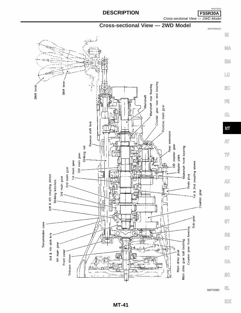
Cross-sectional View — 2WD ModelNEMT0005S01
SMT209D
GI
MA
EM
LC
EC
FE
CL
AT
TF
PD
AX
SU
BR
ST
RS
BT
HA
SC
EL
IDX
DESCRIPTION FS5R30ACross-sectional View — 2WD Model
MT-41

Cross-sectional View — 4WD ModelNEMT0005S02
SMT320D
DESCRIPTION FS5R30ACross-sectional View — 4WD Model
MT-42

SMT479CA
Replacing Rear Oil Seal — 2WD ModelNEMT0003
REMOVALNEMT0003S01
SMT480CA
INSTALLATIONNEMT0003S02
GI
MA
EM
LC
EC
FE
CL
AT
TF
PD
AX
SU
BR
ST
RS
BT
HA
SC
EL
IDX
ON-VEHICLE SERVICE FS5R30AReplacing Rear Oil Seal — 2WD Model
MT-43
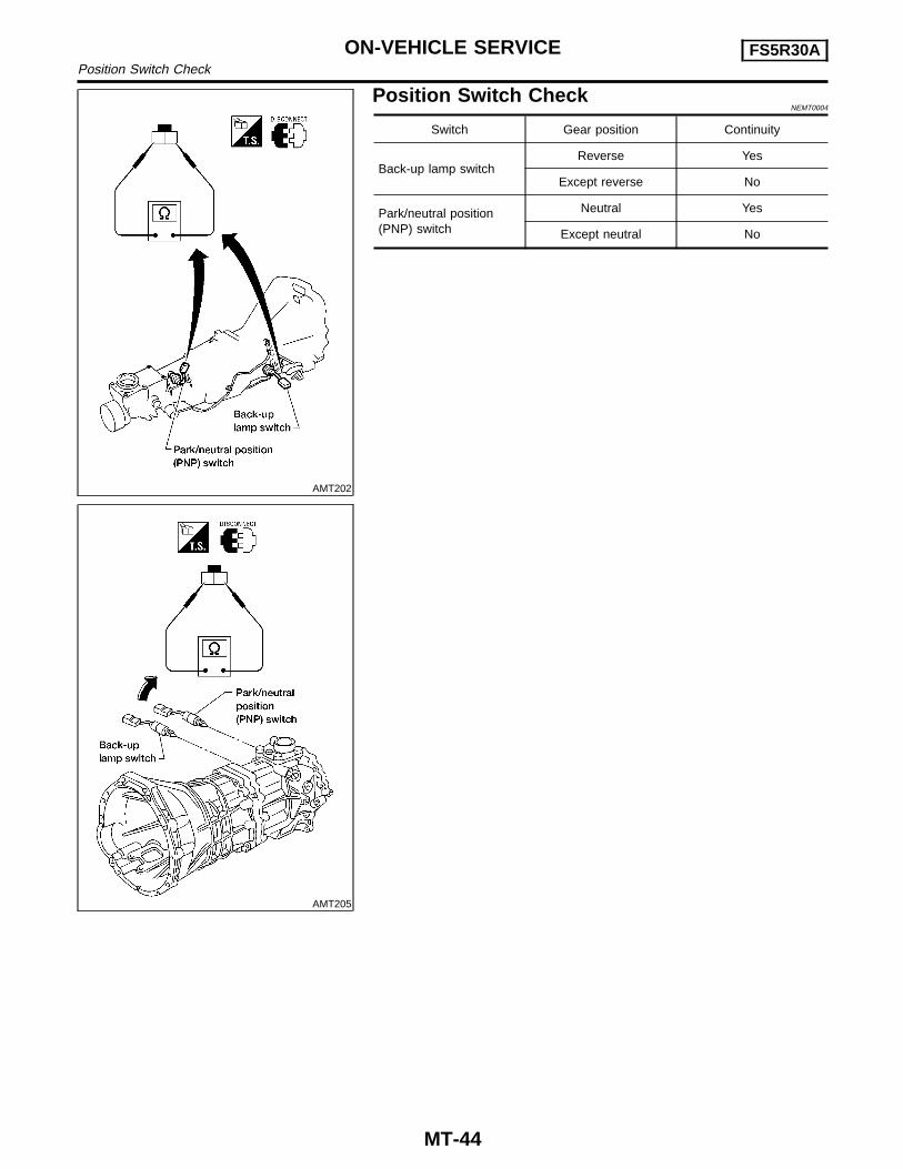
AMT202
AMT205
Position Switch CheckNEMT0004
Switch Gear position Continuity
Back-up lamp switchReverse Yes
Except reverse No
Park/neutral position(PNP) switch
Neutral Yes
Except neutral No
ON-VEHICLE SERVICE FS5R30APosition Switch Check
MT-44
NEMT0006
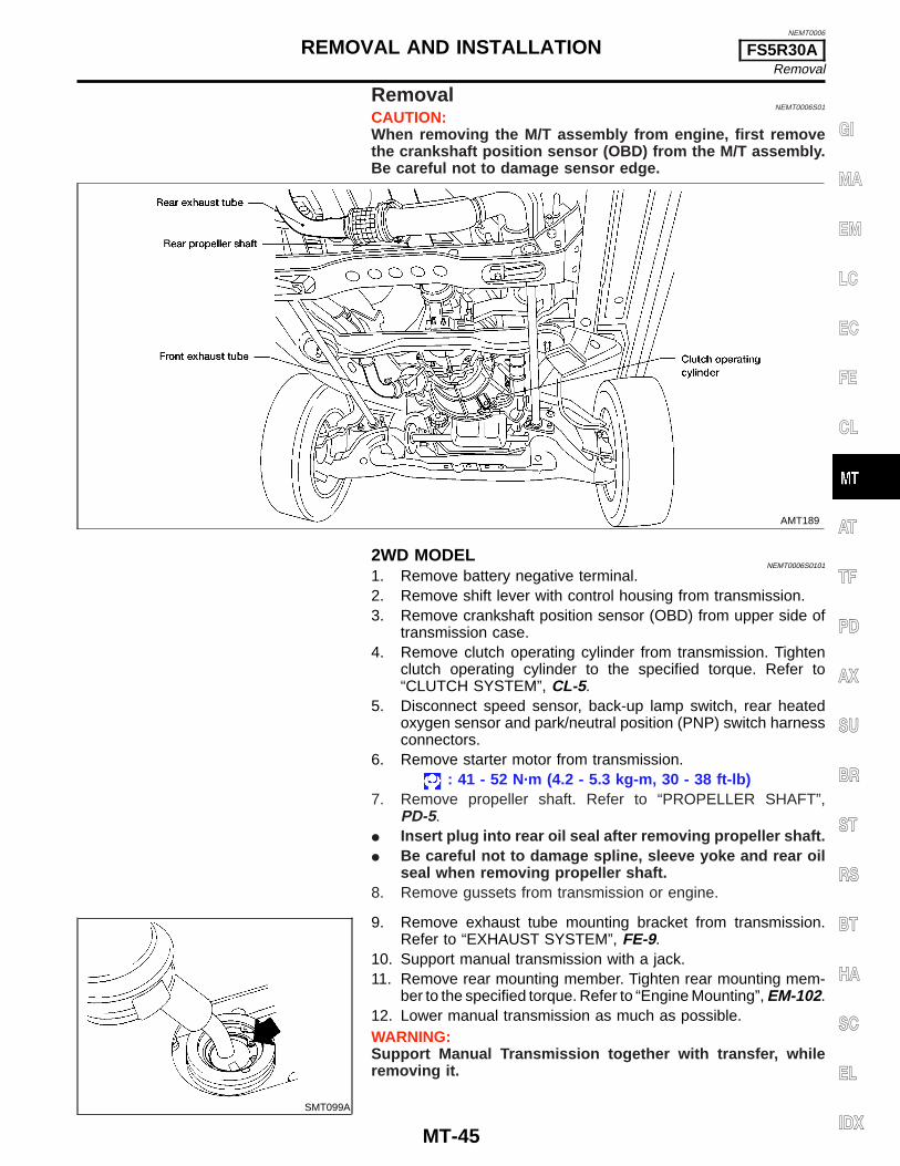
RemovalNEMT0006S01
CAUTION:When removing the M/T assembly from engine, first removethe crankshaft position sensor (OBD) from the M/T assembly.Be careful not to damage sensor edge.
AMT189
2WD MODELNEMT0006S0101
1. Remove battery negative terminal.2. Remove shift lever with control housing from transmission.3. Remove crankshaft position sensor (OBD) from upper side of
transmission case.4. Remove clutch operating cylinder from transmission. Tighten
clutch operating cylinder to the specified torque. Refer to“CLUTCH SYSTEM”, CL-5.
5. Disconnect speed sensor, back-up lamp switch, rear heatedoxygen sensor and park/neutral position (PNP) switch harnessconnectors.
6. Remove starter motor from transmission.: 41 - 52 N·m (4.2 - 5.3 kg-m, 30 - 38 ft-lb)
7. Remove propeller shaft. Refer to “PROPELLER SHAFT”,PD-5.
I Insert plug into rear oil seal after removing propeller shaft.I Be careful not to damage spline, sleeve yoke and rear oil
seal when removing propeller shaft.8. Remove gussets from transmission or engine.
SMT099A
9. Remove exhaust tube mounting bracket from transmission.Refer to “EXHAUST SYSTEM”, FE-9.
10. Support manual transmission with a jack.11. Remove rear mounting member. Tighten rear mounting mem-
ber to the specified torque. Refer to “Engine Mounting”, EM-102.12. Lower manual transmission as much as possible.WARNING:Support Manual Transmission together with transfer, whileremoving it.
GI
MA
EM
LC
EC
FE
CL
AT
TF
PD
AX
SU
BR
ST
RS
BT
HA
SC
EL
IDX
REMOVAL AND INSTALLATION FS5R30ARemoval
MT-45
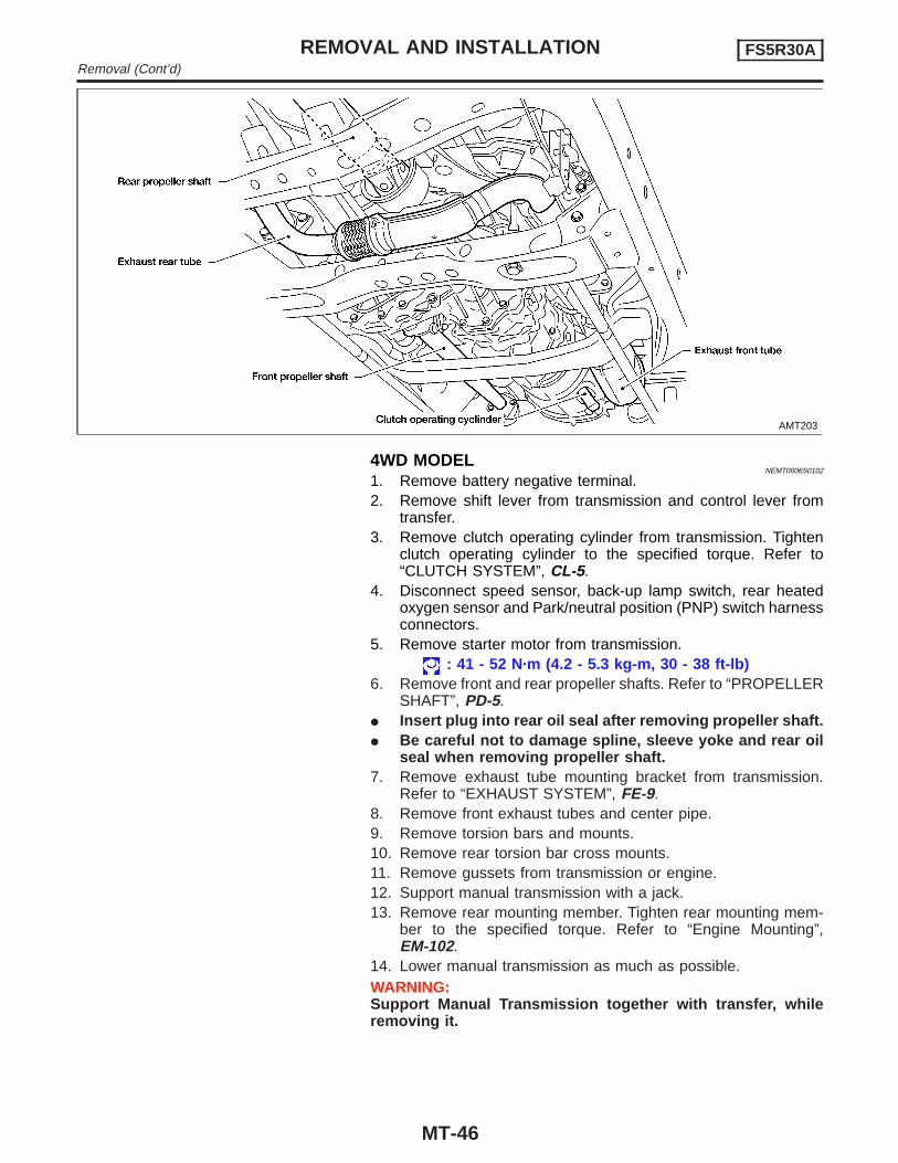
AMT203
4WD MODELNEMT0006S0102
1. Remove battery negative terminal.2. Remove shift lever from transmission and control lever from
transfer.3. Remove clutch operating cylinder from transmission. Tighten
clutch operating cylinder to the specified torque. Refer to“CLUTCH SYSTEM”, CL-5.
4. Disconnect speed sensor, back-up lamp switch, rear heatedoxygen sensor and Park/neutral position (PNP) switch harnessconnectors.
5. Remove starter motor from transmission.: 41 - 52 N·m (4.2 - 5.3 kg-m, 30 - 38 ft-lb)
6. Remove front and rear propeller shafts. Refer to “PROPELLERSHAFT”, PD-5.
I Insert plug into rear oil seal after removing propeller shaft.I Be careful not to damage spline, sleeve yoke and rear oil
seal when removing propeller shaft.7. Remove exhaust tube mounting bracket from transmission.
Refer to “EXHAUST SYSTEM”, FE-9.8. Remove front exhaust tubes and center pipe.9. Remove torsion bars and mounts.10. Remove rear torsion bar cross mounts.11. Remove gussets from transmission or engine.12. Support manual transmission with a jack.13. Remove rear mounting member. Tighten rear mounting mem-
ber to the specified torque. Refer to “Engine Mounting”,EM-102.
14. Lower manual transmission as much as possible.WARNING:Support Manual Transmission together with transfer, whileremoving it.
REMOVAL AND INSTALLATION FS5R30ARemoval (Cont’d)
MT-46
SMT558A
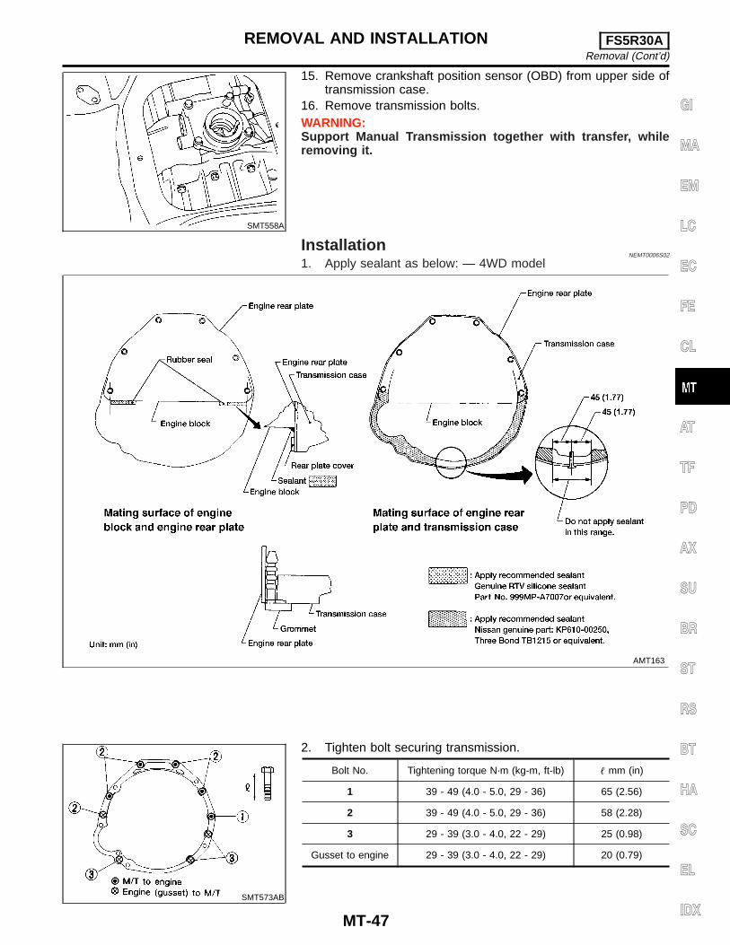
15. Remove crankshaft position sensor (OBD) from upper side oftransmission case.
16. Remove transmission bolts.WARNING:Support Manual Transmission together with transfer, whileremoving it.
InstallationNEMT0006S02
1. Apply sealant as below: — 4WD model
AMT163
SMT573AB
2. Tighten bolt securing transmission.
Bolt No. Tightening torque N·m (kg-m, ft-lb) � mm (in)
1 39 - 49 (4.0 - 5.0, 29 - 36) 65 (2.56)
2 39 - 49 (4.0 - 5.0, 29 - 36) 58 (2.28)
3 29 - 39 (3.0 - 4.0, 22 - 29) 25 (0.98)
Gusset to engine 29 - 39 (3.0 - 4.0, 22 - 29) 20 (0.79)
GI
MA
EM
LC
EC
FE
CL
AT
TF
PD
AX
SU
BR
ST
RS
BT
HA
SC
EL
IDX
REMOVAL AND INSTALLATION FS5R30ARemoval (Cont’d)
MT-47
NEMT0007
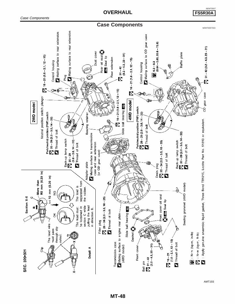
Case ComponentsNEMT0007S01
AMT193
OVERHAUL FS5R30ACase Components
MT-48
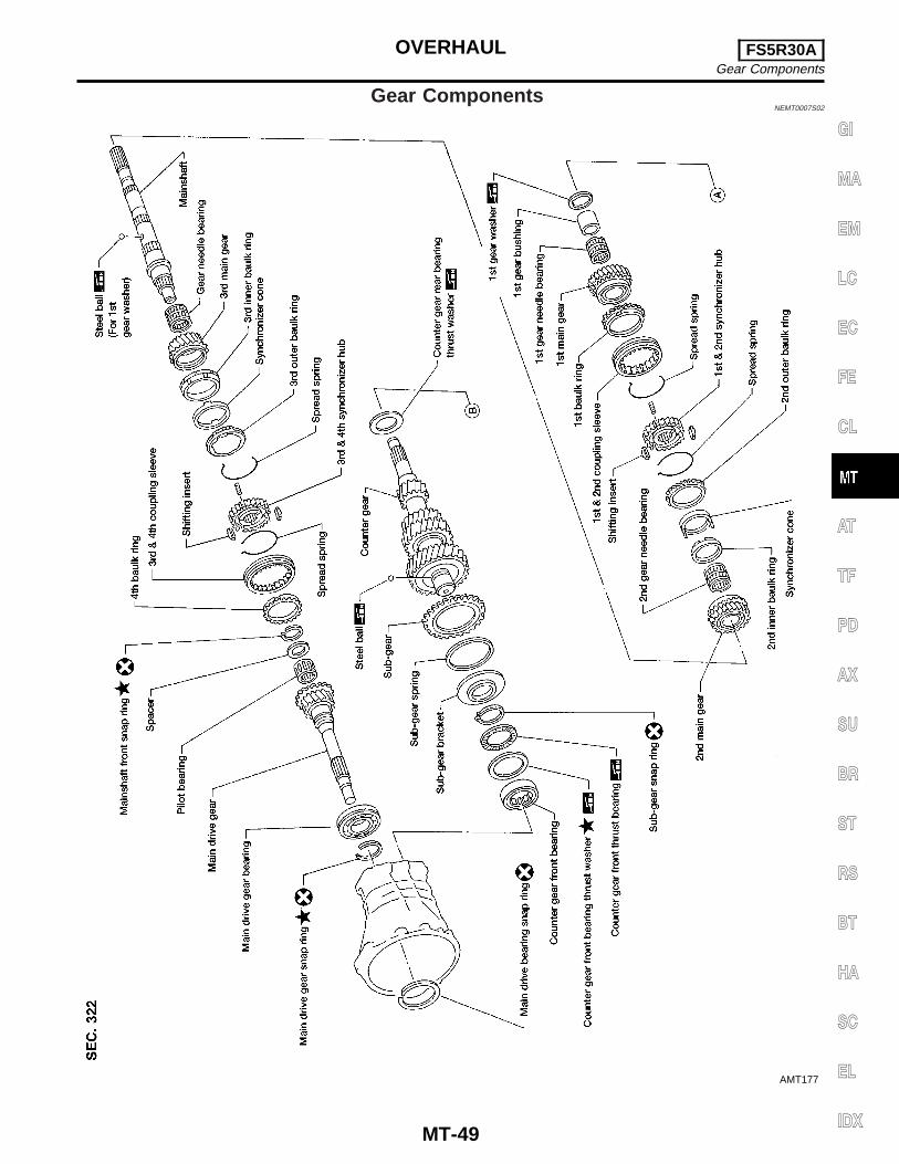
Gear ComponentsNEMT0007S02
AMT177
GI
MA
EM
LC
EC
FE
CL
AT
TF
PD
AX
SU
BR
ST
RS
BT
HA
SC
EL
IDX
OVERHAUL FS5R30AGear Components
MT-49
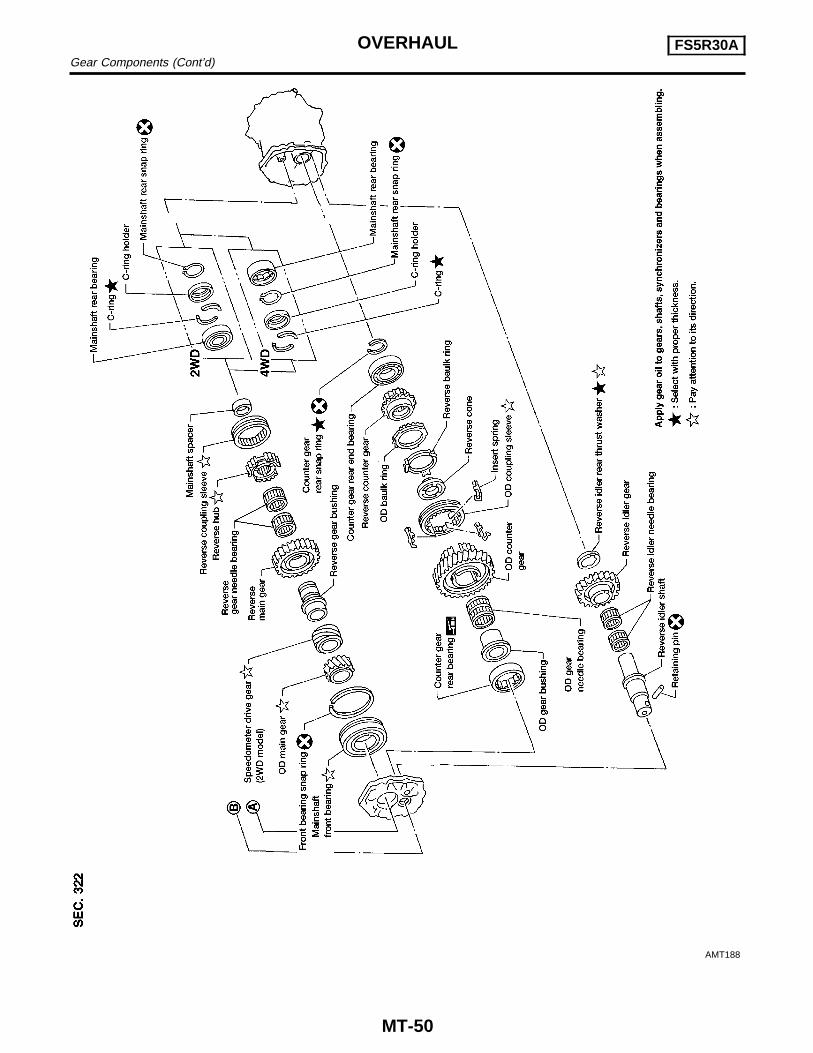
AMT188
OVERHAUL FS5R30AGear Components (Cont’d)
MT-50
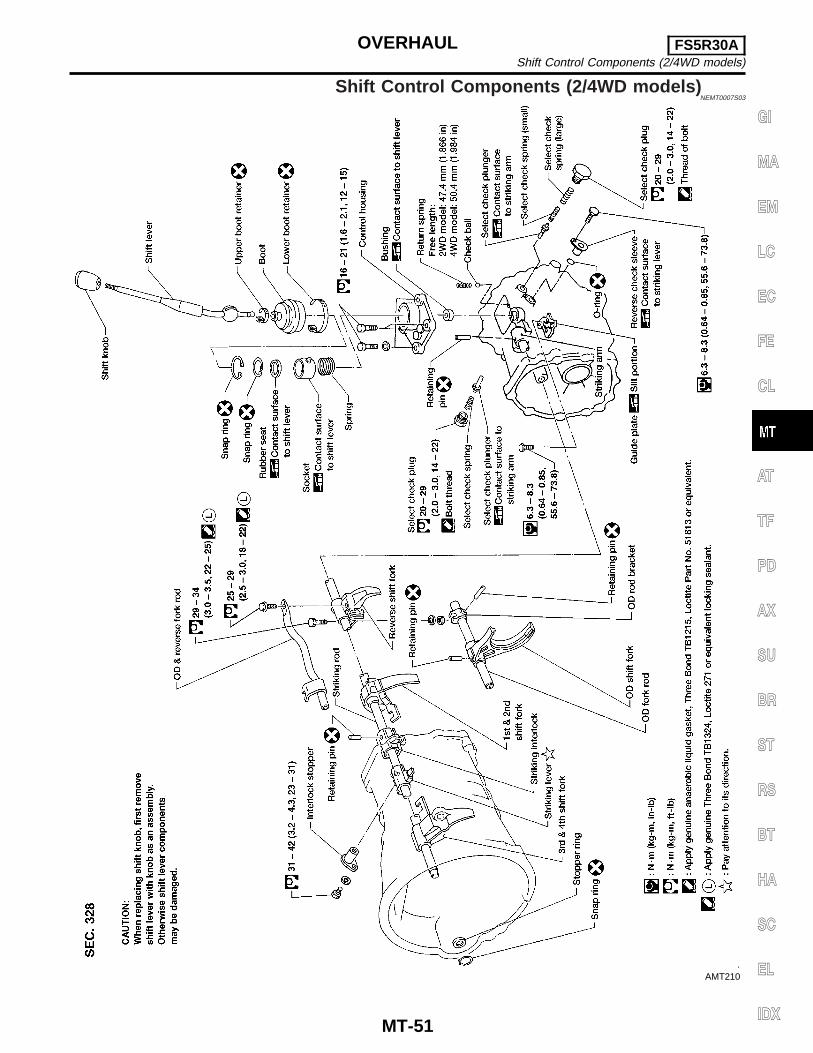
Shift Control Components (2/4WD models)NEMT0007S03
AMT210
GI
MA
EM
LC
EC
FE
CL
AT
TF
PD
AX
SU
BR
ST
RS
BT
HA
SC
EL
IDX
OVERHAUL FS5R30AShift Control Components (2/4WD models)
MT-51
SMT366A
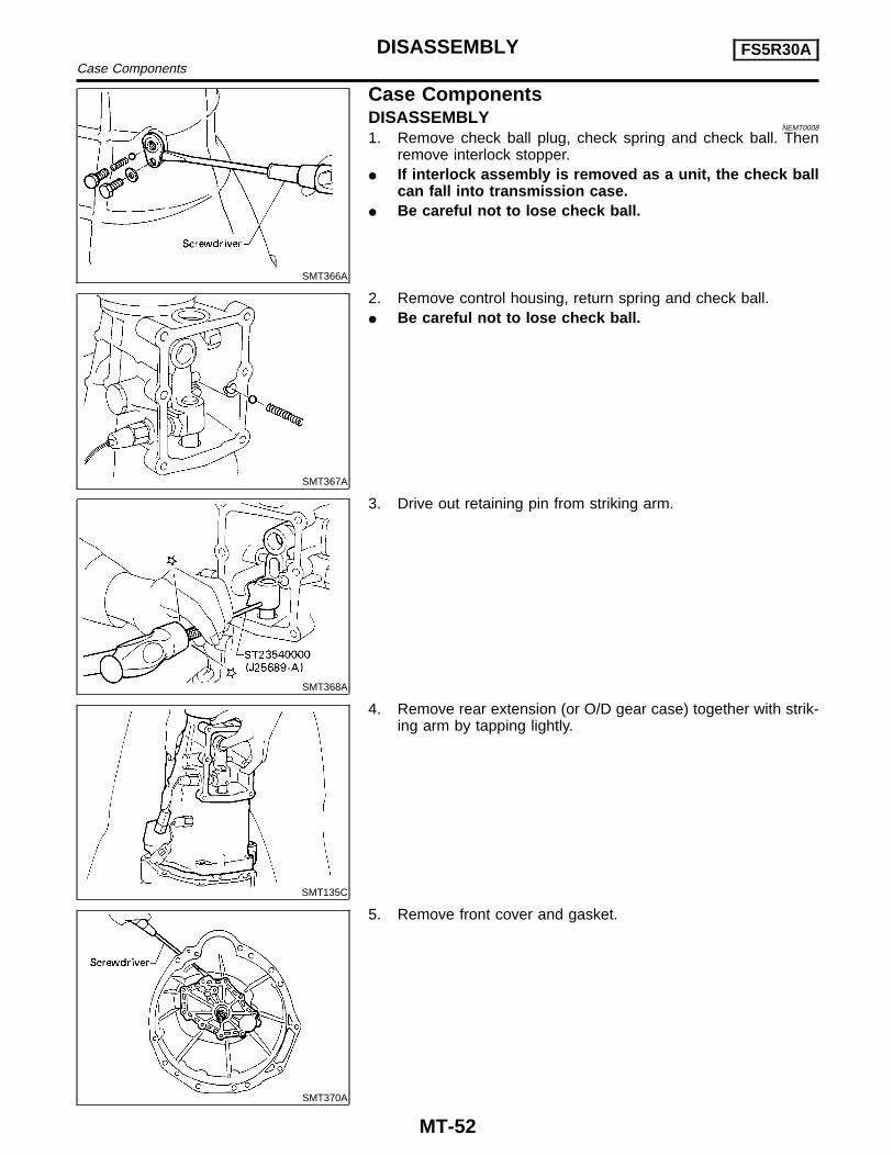
Case ComponentsDISASSEMBLY
NEMT0008
1. Remove check ball plug, check spring and check ball. Thenremove interlock stopper.
I If interlock assembly is removed as a unit, the check ballcan fall into transmission case.
I Be careful not to lose check ball.
SMT367A
2. Remove control housing, return spring and check ball.I Be careful not to lose check ball.
SMT368A
3. Drive out retaining pin from striking arm.
SMT135C
4. Remove rear extension (or O/D gear case) together with strik-ing arm by tapping lightly.
SMT370A
5. Remove front cover and gasket.
DISASSEMBLY FS5R30ACase Components
MT-52
SMT371A
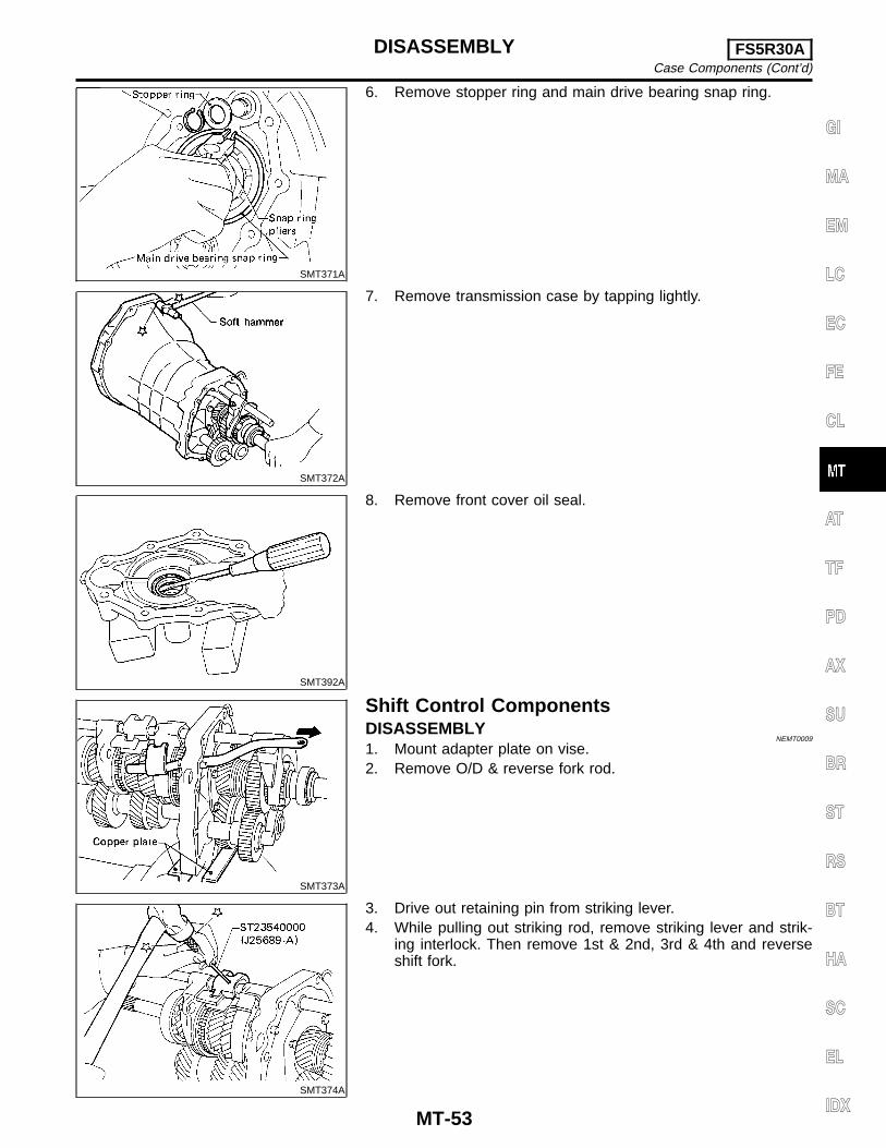
6. Remove stopper ring and main drive bearing snap ring.
SMT372A
7. Remove transmission case by tapping lightly.
SMT392A
8. Remove front cover oil seal.
SMT373A
Shift Control ComponentsDISASSEMBLY
NEMT0009
1. Mount adapter plate on vise.2. Remove O/D & reverse fork rod.
SMT374A
3. Drive out retaining pin from striking lever.4. While pulling out striking rod, remove striking lever and strik-
ing interlock. Then remove 1st & 2nd, 3rd & 4th and reverseshift fork.
GI
MA
EM
LC
EC
FE
CL
AT
TF
PD
AX
SU
BR
ST
RS
BT
HA
SC
EL
IDX
DISASSEMBLY FS5R30ACase Components (Cont’d)
MT-53
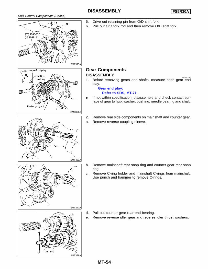
SMT375A
5. Drive out retaining pin from O/D shift fork.6. Pull out O/D fork rod and then remove O/D shift fork.
SMT376A
Gear ComponentsDISASSEMBLY
NEMT0010
1. Before removing gears and shafts, measure each gear endplay.
Gear end play:Refer to SDS, MT-71.
I If not within specification, disassemble and check contact sur-face of gear to hub, washer, bushing, needle bearing and shaft.
SMT463A
2. Remove rear side components on mainshaft and counter gear.a. Remove reverse coupling sleeve.
SMT377A
b. Remove mainshaft rear snap ring and counter gear rear snapring.
c. Remove C-ring holder and mainshaft C-rings from mainshaft.Use punch and hammer to remove C-rings.
SMT378A
d. Pull out counter gear rear end bearing.e. Remove reverse idler gear and reverse idler thrust washers.
DISASSEMBLY FS5R30AShift Control Components (Cont’d)
MT-54
SMT379A
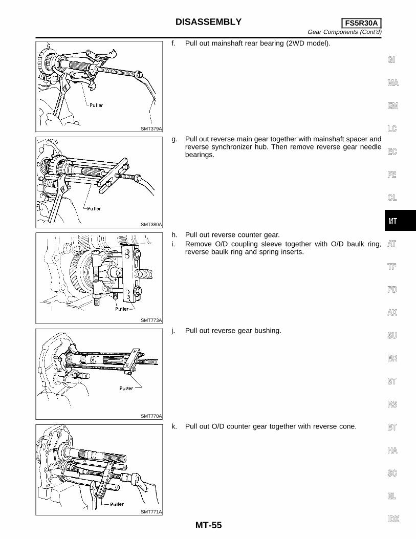
f. Pull out mainshaft rear bearing (2WD model).
SMT380A
g. Pull out reverse main gear together with mainshaft spacer andreverse synchronizer hub. Then remove reverse gear needlebearings.
SMT773A
h. Pull out reverse counter gear.i. Remove O/D coupling sleeve together with O/D baulk ring,
reverse baulk ring and spring inserts.
SMT770A
j. Pull out reverse gear bushing.
SMT771A
k. Pull out O/D counter gear together with reverse cone.
GI
MA
EM
LC
EC
FE
CL
AT
TF
PD
AX
SU
BR
ST
RS
BT
HA
SC
EL
IDX
DISASSEMBLY FS5R30AGear Components (Cont’d)
MT-55
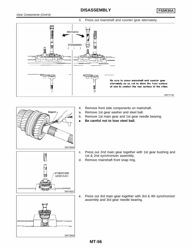
3. Press out mainshaft and counter gear alternately.
AMT174A
SMT383A
4. Remove front side components on mainshaft.a. Remove 1st gear washer and steel ball.b. Remove 1st main gear and 1st gear needle bearing.I Be careful not to lose steel ball.
SMT482C
c. Press out 2nd main gear together with 1st gear bushing and1st & 2nd synchronizer assembly.
d. Remove mainshaft front snap ring.
SMT385A
e. Press out 3rd main gear together with 3rd & 4th synchronizerassembly and 3rd gear needle bearing.
DISASSEMBLY FS5R30AGear Components (Cont’d)
MT-56

SMT404A
5. Remove front side components on counter gear.a. Remove counter gear rear thrust bearing.
SMT470A
b. Remove sub-gear components.
SMT420A
6. Remove main drive gear bearing.a. Remove main drive gear snap ring.b. Press out main drive gear bearing.
7. Remove bearings from case components.
AMT173
GI
MA
EM
LC
EC
FE
CL
AT
TF
PD
AX
SU
BR
ST
RS
BT
HA
SC
EL
IDX
DISASSEMBLY FS5R30AGear Components (Cont’d)
MT-57
SMT398A
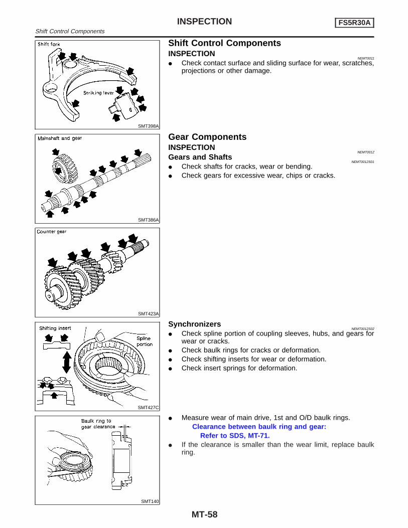
Shift Control ComponentsINSPECTION
NEMT0011
I Check contact surface and sliding surface for wear, scratches,projections or other damage.
SMT386A
SMT423A
Gear ComponentsINSPECTION
NEMT0012
Gears and ShaftsNEMT0012S01
I Check shafts for cracks, wear or bending.I Check gears for excessive wear, chips or cracks.
SMT427C
SynchronizersNEMT0012S02
I Check spline portion of coupling sleeves, hubs, and gears forwear or cracks.
I Check baulk rings for cracks or deformation.I Check shifting inserts for wear or deformation.I Check insert springs for deformation.
SMT140
I Measure wear of main drive, 1st and O/D baulk rings.Clearance between baulk ring and gear:
Refer to SDS, MT-71.I If the clearance is smaller than the wear limit, replace baulk
ring.
INSPECTION FS5R30AShift Control Components
MT-58

SMT041B
SMT042B
I Measure wear of 2nd and 3rd baulk rings.a) Place baulk rings in position on synchronizer cone.b) While holding baulk rings against synchronizer cone as far as
it will go, measure dimensions “A” and “B”.Standard:
A 0.7 - 0.9 mm (0.028 - 0.035 in)B 0.6 - 1.1 mm (0.024 - 0.043 in)
Wear limit:0.2 mm (0.008 in)
I If dimension “A” or “B” is smaller than the wear limit, replaceouter baulk ring, inner baulk ring and synchronizer cone as aset.
SMT424A
I Measure wear of reverse baulk ring.a) Place baulk ring in position on reverse cone.b) While holding baulk ring against reverse cone as far as it will
go, measure dimension “A” with dial indicator.Dimension “A”:
Standard −0.1 to 0.35 mm (−0.0039 to 0.0138 in)Wear limit 0.7 mm (0.028 in)
c) If dimension “A” is larger than the wear limit, replace baulk ring.
SMT418A
BearingsNEMT0012S03
I Make sure bearings roll freely and are free from noise, crack,pitting or wear.
GI
MA
EM
LC
EC
FE
CL
AT
TF
PD
AX
SU
BR
ST
RS
BT
HA
SC
EL
IDX
INSPECTION FS5R30AGear Components (Cont’d)
MT-59
Gear ComponentsASSEMBLY
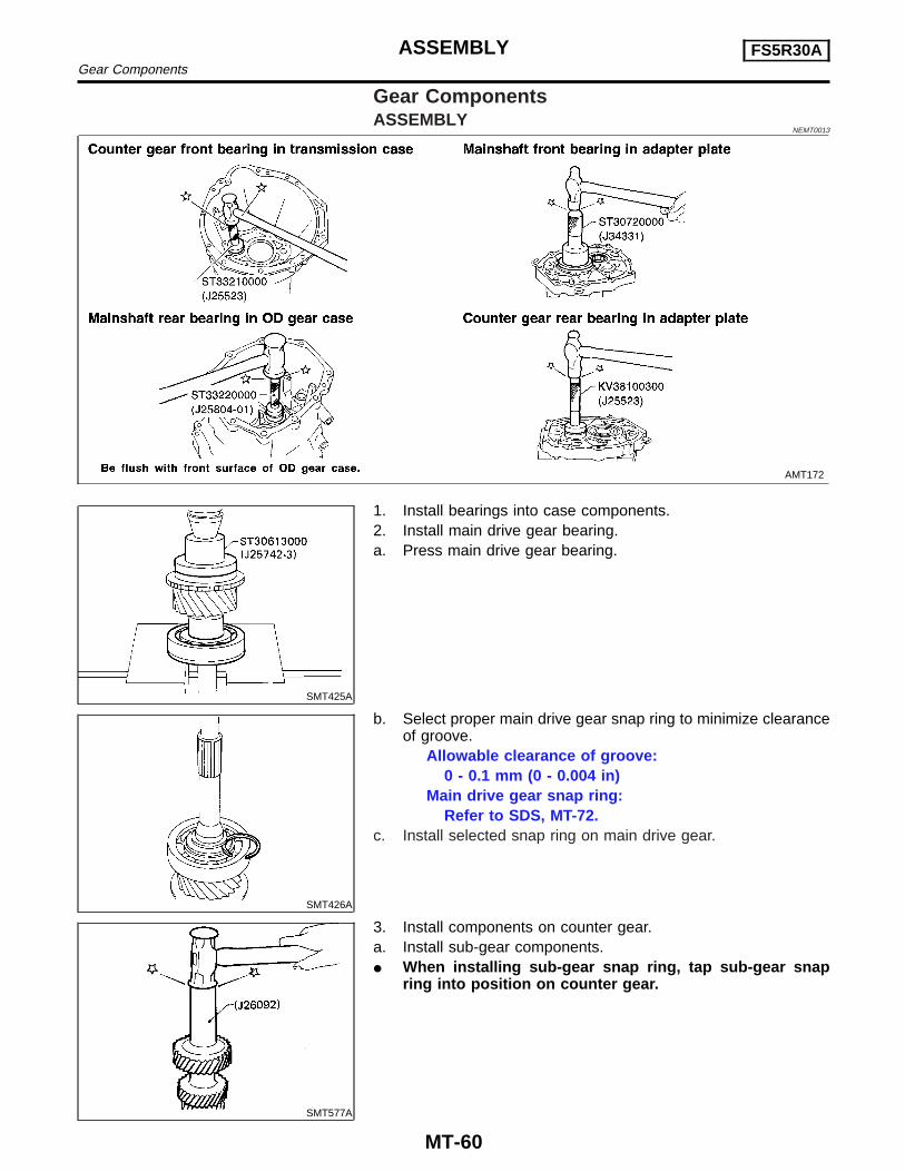
NEMT0013
AMT172
SMT425A
1. Install bearings into case components.2. Install main drive gear bearing.a. Press main drive gear bearing.
SMT426A
b. Select proper main drive gear snap ring to minimize clearanceof groove.
Allowable clearance of groove:0 - 0.1 mm (0 - 0.004 in)
Main drive gear snap ring:Refer to SDS, MT-72.
c. Install selected snap ring on main drive gear.
SMT577A
3. Install components on counter gear.a. Install sub-gear components.I When installing sub-gear snap ring, tap sub-gear snap
ring into position on counter gear.
ASSEMBLY FS5R30AGear Components
MT-60
SMT405A
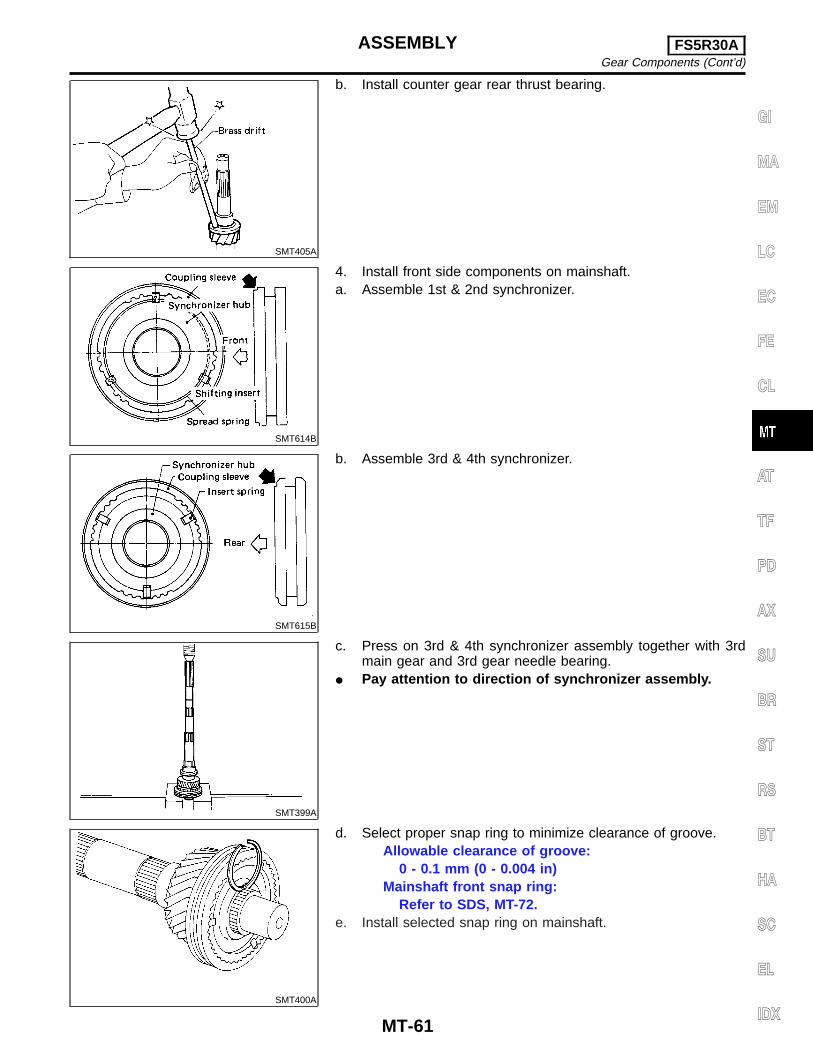
b. Install counter gear rear thrust bearing.
SMT614B
4. Install front side components on mainshaft.a. Assemble 1st & 2nd synchronizer.
SMT615B
b. Assemble 3rd & 4th synchronizer.
SMT399A
c. Press on 3rd & 4th synchronizer assembly together with 3rdmain gear and 3rd gear needle bearing.
I Pay attention to direction of synchronizer assembly.
SMT400A
d. Select proper snap ring to minimize clearance of groove.Allowable clearance of groove:
0 - 0.1 mm (0 - 0.004 in)Mainshaft front snap ring:
Refer to SDS, MT-72.e. Install selected snap ring on mainshaft.
GI
MA
EM
LC
EC
FE
CL
AT
TF
PD
AX
SU
BR
ST
RS
BT
HA
SC
EL
IDX
ASSEMBLY FS5R30AGear Components (Cont’d)
MT-61

SMT401A
f. Press on 1st & 2nd synchronizer assembly together with 2ndmain gear and 2nd gear needle bearing.
SMT402A
g. Press on 1st gear bushing using 1st gear washer.h. Install 1st main gear and needle bearing.
SMT403A
i. Install steel ball and 1st gear washer.I Apply multi-purpose grease to steel ball and 1st gear
washer before installing.
SMT427AA
5. Select proper counter gear front bearing thrust washer whenreplacing transmission case, counter gear, counter gear rearthrust bearing or sub-gear components.
a. Install counter gear with sub-gear components, counter gearfront and rear bearing thrust washer on adapter plate.
b. Remove counter gear front bearing thrust washer from trans-mission case.
c. Place adapter plate and counter gear assembly in transmis-sion case (case inverted).
ASSEMBLY FS5R30AGear Components (Cont’d)
MT-62

SMT578A
d. Tighten adapter plate to transmission case using 2 bolts.e. Place dial indicator on rear end of counter gear.f. Move counter gear up and down and measure dial indicator
deflection.g. Select proper thrust washer using table below as a guide.
Counter gear end play:0.10 - 0.25 mm (0.0039 - 0.0098 in)
Table for selecting proper counter gear front bearingthrust washer:
Refer to SDS, MT-73.
AMT204
6. Select proper reverse idler rear thrust washer when replacingrear extension (or O/D gear case), reverse idler gear, reverseidler shaft or reverse idler front thrust washer.
a. Install reverse idler gear, reverse idler needle bearings,reverse idler front thrust washers and reverse idler shaft intorear extension (or O/D gear case).
I When replacing reverse idler rear thrust washer, installeither A or B.
Reverse idler rear thrust washer:Refer to SDS, MT-73.
GI
MA
EM
LC
EC
FE
CL
AT
TF
PD
AX
SU
BR
ST
RS
BT
HA
SC
EL
IDX
ASSEMBLY FS5R30AGear Components (Cont’d)
MT-63
SMT433A
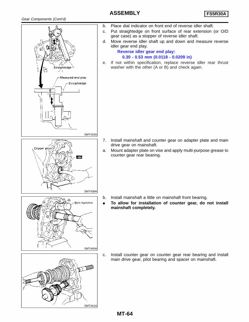
b. Place dial indicator on front end of reverse idler shaft.c. Put straightedge on front surface of rear extension (or O/D
gear case) as a stopper of reverse idler shaft.d. Move reverse idler shaft up and down and measure reverse
idler gear end play.Reverse idler gear end play:
0.30 - 0.53 mm (0.0118 - 0.0209 in)e. If not within specification, replace reverse idler rear thrust
washer with the other (A or B) and check again.
SMT438A
7. Install mainshaft and counter gear on adapter plate and maindrive gear on mainshaft.
a. Mount adapter plate on vise and apply multi-purpose grease tocounter gear rear bearing.
SMT440A
b. Install mainshaft a little on mainshaft front bearing.I To allow for installation of counter gear, do not install
mainshaft completely.
SMT441A
c. Install counter gear on counter gear rear bearing and installmain drive gear, pilot bearing and spacer on mainshaft.
ASSEMBLY FS5R30AGear Components (Cont’d)
MT-64

SMT442A
I When installing counter gear into counter gear rearbearing, push up on upper roller of counter gear rear bear-ing with screwdriver.
SMT064C
d. Install Tools (J26349-3) onto adapter plate and C-ring andC-ring holder on mainshaft.
e. Install Tool (J34328) on mainshaft.
SMT579A
f. Install mainshaft and counter gear completely by extendinglength of (J26349-3).
SMT444A
8. Install rear side components on mainshaft and counter gear.a. Install O/D gear bushing while pushing on the front of counter
gear.
SMT580AA
b. Install O/D main gear.I Pay attention to direction of O/D main gear. (B is wider
than A as shown at left.)c. Install adapter plate with gear assembly onto transmission
case.d. Install O/D gear needle bearing and then install O/D counter
gear and reverse idler shaft.
GI
MA
EM
LC
EC
FE
CL
AT
TF
PD
AX
SU
BR
ST
RS
BT
HA
SC
EL
IDX
ASSEMBLY FS5R30AGear Components (Cont’d)
MT-65
SMT581A
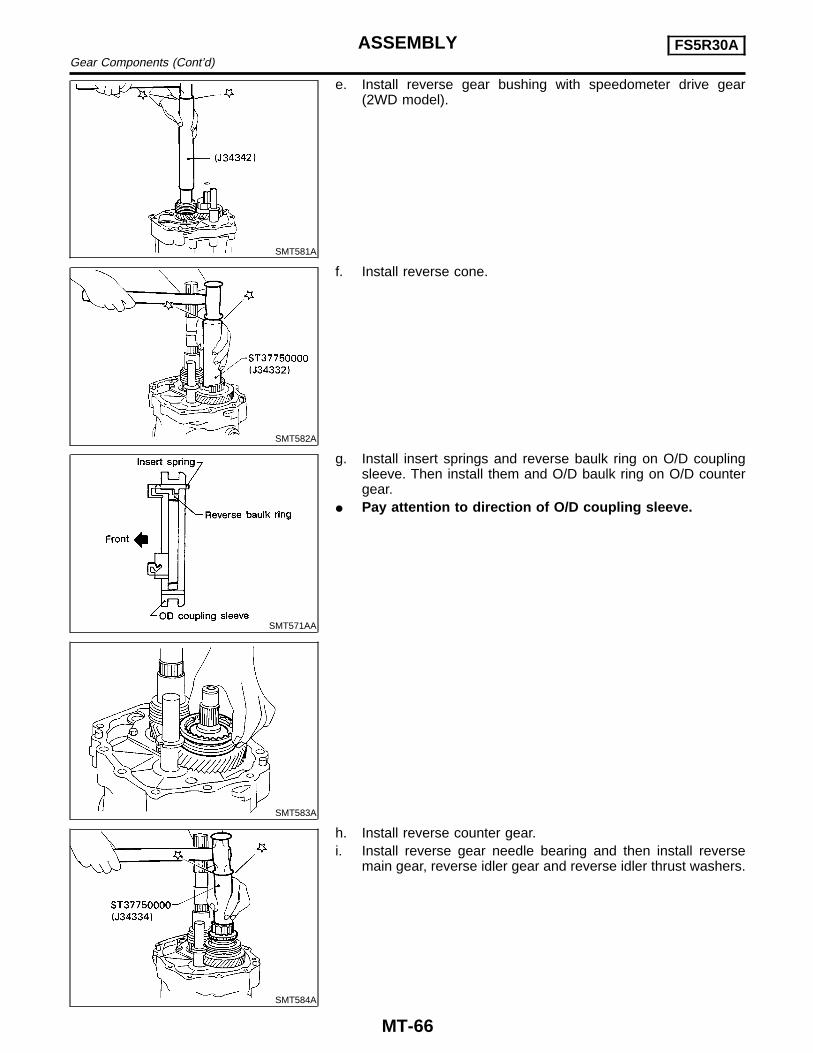
e. Install reverse gear bushing with speedometer drive gear(2WD model).
SMT582A
f. Install reverse cone.
SMT571AA
SMT583A
g. Install insert springs and reverse baulk ring on O/D couplingsleeve. Then install them and O/D baulk ring on O/D countergear.
I Pay attention to direction of O/D coupling sleeve.
SMT584A
h. Install reverse counter gear.i. Install reverse gear needle bearing and then install reverse
main gear, reverse idler gear and reverse idler thrust washers.
ASSEMBLY FS5R30AGear Components (Cont’d)
MT-66
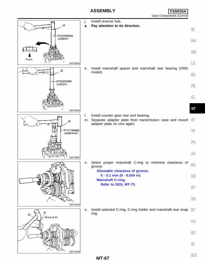
SMT585A
j. Install reverse hub.I Pay attention to its direction.
SMT586A
k. Install mainshaft spacer and mainshaft rear bearing (2WDmodel).
SMT485C
l. Install counter gear rear end bearing.m. Separate adapter plate from transmission case and mount
adapter plate on vice again.
SMT452A
n. Select proper mainshaft C-ring to minimize clearance ofgroove.
Allowable clearance of groove:0 - 0.1 mm (0 - 0.004 in)
Mainshaft C-ring:Refer to SDS, MT-73.
SMT454A
o. Install selected C-ring, C-ring holder and mainshaft rear snapring.
GI
MA
EM
LC
EC
FE
CL
AT
TF
PD
AX
SU
BR
ST
RS
BT
HA
SC
EL
IDX
ASSEMBLY FS5R30AGear Components (Cont’d)
MT-67
SMT453A
SMT455A
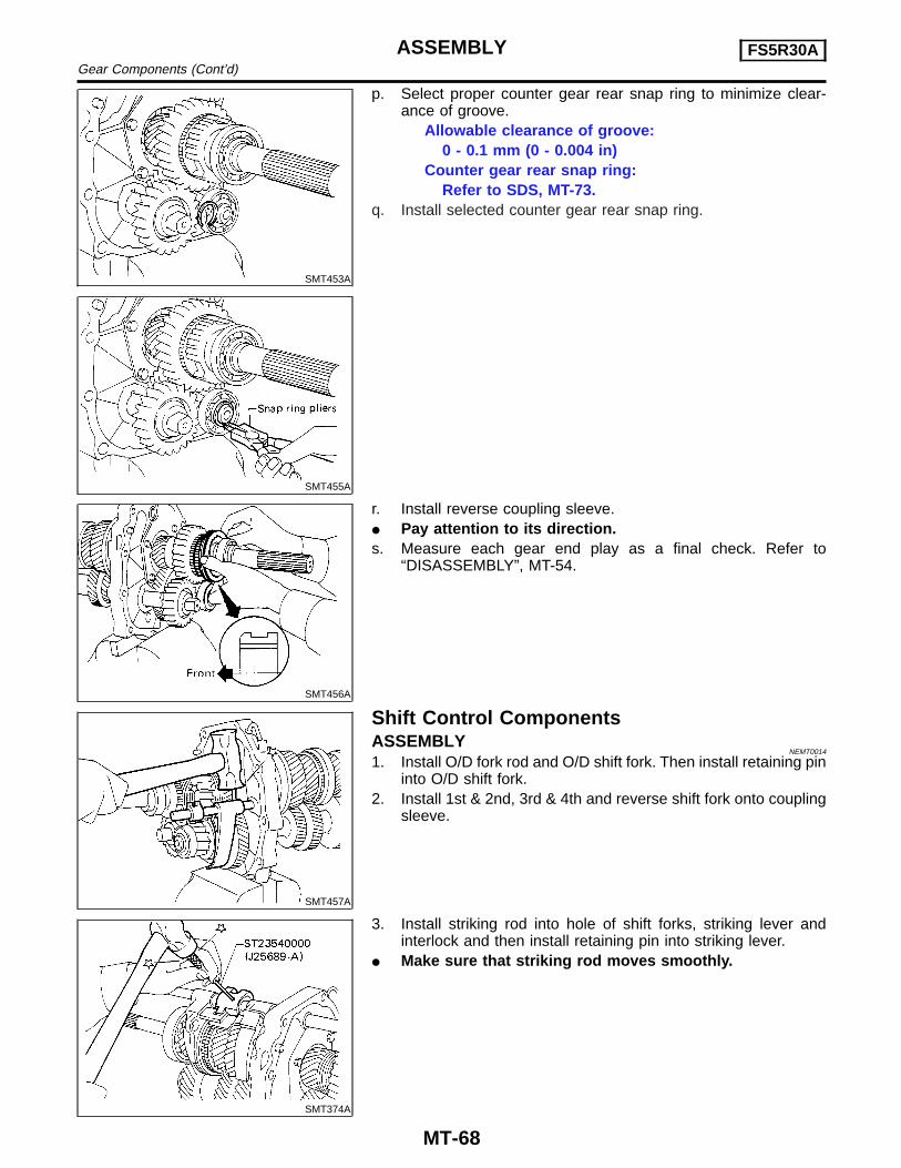
p. Select proper counter gear rear snap ring to minimize clear-ance of groove.
Allowable clearance of groove:0 - 0.1 mm (0 - 0.004 in)
Counter gear rear snap ring:Refer to SDS, MT-73.
q. Install selected counter gear rear snap ring.
SMT456A
r. Install reverse coupling sleeve.I Pay attention to its direction.s. Measure each gear end play as a final check. Refer to
“DISASSEMBLY”, MT-54.
SMT457A
Shift Control ComponentsASSEMBLY
NEMT0014
1. Install O/D fork rod and O/D shift fork. Then install retaining pininto O/D shift fork.
2. Install 1st & 2nd, 3rd & 4th and reverse shift fork onto couplingsleeve.
SMT374A
3. Install striking rod into hole of shift forks, striking lever andinterlock and then install retaining pin into striking lever.
I Make sure that striking rod moves smoothly.
ASSEMBLY FS5R30AGear Components (Cont’d)
MT-68
SMT393A
Case ComponentsASSEMBLY
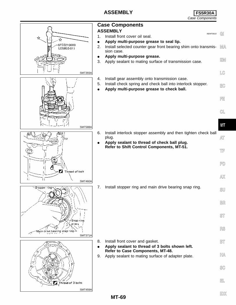
NEMT0015
1. Install front cover oil seal.I Apply multi-purpose grease to seal lip.2. Install selected counter gear front bearing shim onto transmis-
sion case.I Apply multi-purpose grease.3. Apply sealant to mating surface of transmission case.
SMT588A
4. Install gear assembly onto transmission case.5. Install check spring and check ball into interlock stopper.I Apply multi-purpose grease to check ball.
SMT460A
6. Install interlock stopper assembly and then tighten check ballplug.
I Apply sealant to thread of check ball plug.Refer to Shift Control Components, MT-51.
SMT371A
7. Install stopper ring and main drive bearing snap ring.
SMT459A
8. Install front cover and gasket.I Apply sealant to thread of 3 bolts shown left.
Refer to Case Components, MT-48.9. Apply sealant to mating surface of adapter plate.
GI
MA
EM
LC
EC
FE
CL
AT
TF
PD
AX
SU
BR
ST
RS
BT
HA
SC
EL
IDX
ASSEMBLY FS5R30ACase Components
MT-69

SMT461A
10. Install O/D gear case together with striking arm.
SMT368A
11. Install retaining pin into striking arm.
SMT462A
12. Install return spring and check ball and then install controlhousing.
I Apply sealant to mating surface of O/D gear case.Refer to Case Components, MT-48.
SMT572A
13. Tighten control housing bolts.Bolt head size:
A bolts 12 mm (0.47 in)B bolts 13 mm (0.51 in)
ASSEMBLY FS5R30ACase Components (Cont’d)
MT-70
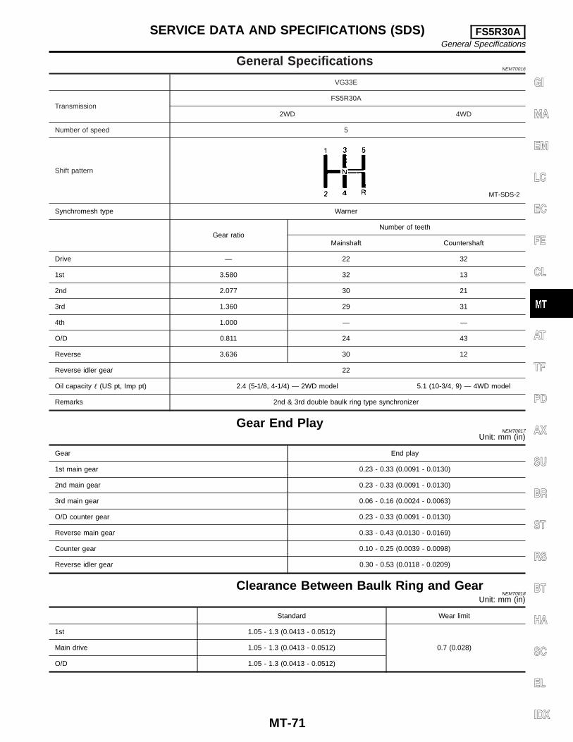
General SpecificationsNEMT0016
VG33E
TransmissionFS5R30A
2WD 4WD
Number of speed 5
Shift pattern
MT-SDS-2
Synchromesh type Warner
Gear ratioNumber of teeth
Mainshaft Countershaft
Drive — 22 32
1st 3.580 32 13
2nd 2.077 30 21
3rd 1.360 29 31
4th 1.000 — —
O/D 0.811 24 43
Reverse 3.636 30 12
Reverse idler gear 22
Oil capacity � (US pt, Imp pt) 2.4 (5-1/8, 4-1/4) — 2WD model 5.1 (10-3/4, 9) — 4WD model
Remarks 2nd & 3rd double baulk ring type synchronizer
Gear End PlayNEMT0017
Unit: mm (in)
Gear End play
1st main gear 0.23 - 0.33 (0.0091 - 0.0130)
2nd main gear 0.23 - 0.33 (0.0091 - 0.0130)
3rd main gear 0.06 - 0.16 (0.0024 - 0.0063)
O/D counter gear 0.23 - 0.33 (0.0091 - 0.0130)
Reverse main gear 0.33 - 0.43 (0.0130 - 0.0169)
Counter gear 0.10 - 0.25 (0.0039 - 0.0098)
Reverse idler gear 0.30 - 0.53 (0.0118 - 0.0209)
Clearance Between Baulk Ring and GearNEMT0018
Unit: mm (in)
Standard Wear limit
1st 1.05 - 1.3 (0.0413 - 0.0512)
0.7 (0.028)Main drive 1.05 - 1.3 (0.0413 - 0.0512)
O/D 1.05 - 1.3 (0.0413 - 0.0512)
GI
MA
EM
LC
EC
FE
CL
AT
TF
PD
AX
SU
BR
ST
RS
BT
HA
SC
EL
IDX
SERVICE DATA AND SPECIFICATIONS (SDS) FS5R30AGeneral Specifications
MT-71
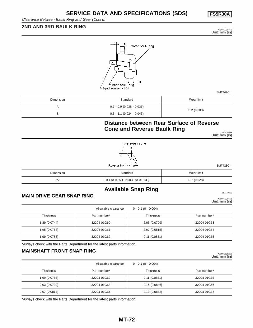
2ND AND 3RD BAULK RINGNEMT0018S01
Unit: mm (in)
SMT742C
Dimension Standard Wear limit
A 0.7 - 0.9 (0.028 - 0.035)0.2 (0.008)
B 0.6 - 1.1 (0.024 - 0.043)
Distance between Rear Surface of ReverseCone and Reverse Baulk Ring
NEMT0019
Unit: mm (in)
SMT428C
Dimension Standard Wear limit
“A” −0.1 to 0.35 (−0.0039 to 0.0138) 0.7 (0.028)
Available Snap RingNEMT0020
MAIN DRIVE GEAR SNAP RINGNEMT0020S01
Unit: mm (in)
Allowable clearance 0 - 0.1 (0 - 0.004)
Thickness Part number* Thickness Part number*
1.89 (0.0744) 32204-01G60 2.03 (0.0799) 32204-01G63
1.95 (0.0768) 32204-01G61 2.07 (0.0815) 32204-01G64
1.99 (0.0783) 32204-01G62 2.11 (0.0831) 32204-01G65
*Always check with the Parts Department for the latest parts information.
MAINSHAFT FRONT SNAP RINGNEMT0020S02
Unit: mm (in)
Allowable clearance 0 - 0.1 (0 - 0.004)
Thickness Part number* Thickness Part number*
1.99 (0.0783) 32204-01G62 2.11 (0.0831) 32204-01G65
2.03 (0.0799) 32204-01G63 2.15 (0.0846) 32204-01G66
2.07 (0.0815) 32204-01G64 2.19 (0.0862) 32204-01G67
*Always check with the Parts Department for the latest parts information.
SERVICE DATA AND SPECIFICATIONS (SDS) FS5R30AClearance Between Baulk Ring and Gear (Cont’d)
MT-72
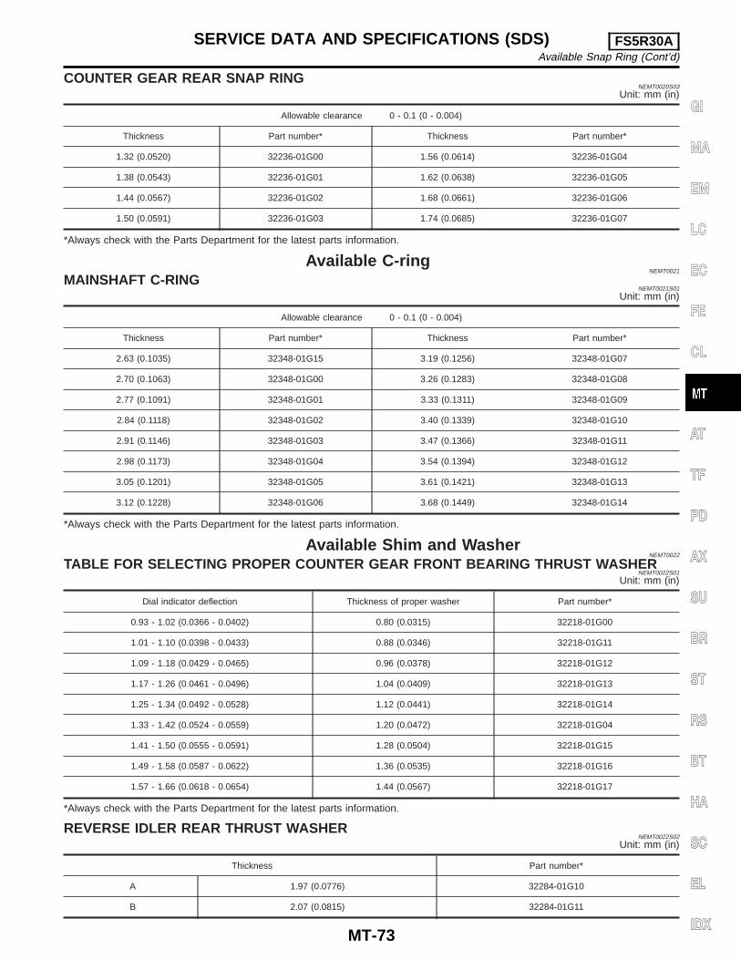
COUNTER GEAR REAR SNAP RINGNEMT0020S03
Unit: mm (in)
Allowable clearance 0 - 0.1 (0 - 0.004)
Thickness Part number* Thickness Part number*
1.32 (0.0520) 32236-01G00 1.56 (0.0614) 32236-01G04
1.38 (0.0543) 32236-01G01 1.62 (0.0638) 32236-01G05
1.44 (0.0567) 32236-01G02 1.68 (0.0661) 32236-01G06
1.50 (0.0591) 32236-01G03 1.74 (0.0685) 32236-01G07
*Always check with the Parts Department for the latest parts information.
Available C-ringNEMT0021
MAINSHAFT C-RINGNEMT0021S01
Unit: mm (in)
Allowable clearance 0 - 0.1 (0 - 0.004)
Thickness Part number* Thickness Part number*
2.63 (0.1035) 32348-01G15 3.19 (0.1256) 32348-01G07
2.70 (0.1063) 32348-01G00 3.26 (0.1283) 32348-01G08
2.77 (0.1091) 32348-01G01 3.33 (0.1311) 32348-01G09
2.84 (0.1118) 32348-01G02 3.40 (0.1339) 32348-01G10
2.91 (0.1146) 32348-01G03 3.47 (0.1366) 32348-01G11
2.98 (0.1173) 32348-01G04 3.54 (0.1394) 32348-01G12
3.05 (0.1201) 32348-01G05 3.61 (0.1421) 32348-01G13
3.12 (0.1228) 32348-01G06 3.68 (0.1449) 32348-01G14
*Always check with the Parts Department for the latest parts information.
Available Shim and WasherNEMT0022
TABLE FOR SELECTING PROPER COUNTER GEAR FRONT BEARING THRUST WASHERNEMT0022S01
Unit: mm (in)
Dial indicator deflection Thickness of proper washer Part number*
0.93 - 1.02 (0.0366 - 0.0402) 0.80 (0.0315) 32218-01G00
1.01 - 1.10 (0.0398 - 0.0433) 0.88 (0.0346) 32218-01G11
1.09 - 1.18 (0.0429 - 0.0465) 0.96 (0.0378) 32218-01G12
1.17 - 1.26 (0.0461 - 0.0496) 1.04 (0.0409) 32218-01G13
1.25 - 1.34 (0.0492 - 0.0528) 1.12 (0.0441) 32218-01G14
1.33 - 1.42 (0.0524 - 0.0559) 1.20 (0.0472) 32218-01G04
1.41 - 1.50 (0.0555 - 0.0591) 1.28 (0.0504) 32218-01G15
1.49 - 1.58 (0.0587 - 0.0622) 1.36 (0.0535) 32218-01G16
1.57 - 1.66 (0.0618 - 0.0654) 1.44 (0.0567) 32218-01G17
*Always check with the Parts Department for the latest parts information.
REVERSE IDLER REAR THRUST WASHERNEMT0022S02
Unit: mm (in)
Thickness Part number*
A 1.97 (0.0776) 32284-01G10
B 2.07 (0.0815) 32284-01G11
GI
MA
EM
LC
EC
FE
CL
AT
TF
PD
AX
SU
BR
ST
RS
BT
HA
SC
EL
IDX
SERVICE DATA AND SPECIFICATIONS (SDS) FS5R30AAvailable Snap Ring (Cont’d)
MT-73
*Always check with the Parts Department for the latest parts information.
SERVICE DATA AND SPECIFICATIONS (SDS) FS5R30AAvailable Shim and Washer (Cont’d)
MT-74