
MANUAL OF STANDARDISATION
98
201 91M~ RP~V ENCE cEN1~ ftflERN~TION~ WPFER FOR CO~~ WAT~ 5UPF~L~ ~ ~~ 5~ment of Lesotho Ministry of Interior, Chieftainship Affairs and Rural Development Village Water Supply Section MANUAL OF STANDARDISATION Planning, Design and Construction of Village Water Supplies Third Edition 1991 ( 201—91NA—10607
Transcript of MANUAL OF STANDARDISATION
201 91M~RP~V ENCE cEN1~
ftflERN~TION~WPFERFOR CO~~ WAT~5UPF~L~~
~~5~ment of Lesotho
Ministry of Interior, Chieftainship Affairs and Rural Development
Village Water Supply Section
MANUAL OF
STANDARDISATION
Planning, Design and Construction
of Village Water Supplies
Third Edition 1991
(
201—91NA—10607

1.
2.
2.12.2
3.
3.13.23.33.43.53.63.7
4.
5.
6.
6.16.26.36.46.5
7.
8.
8.18.2
9.
9.19.29.3
10.
10.110.2
Page 1
3
33
5
56677710
10
11
12
1212121313
14
14
15
1515
151819
19
1919
INDEX AND CONTENT
LIST 0F ABBREVIATIONSLIST OF FORMSLIST OF APPENDICES
PRELIMINARY SURVEY
DETAILED SURVEY
Survey MethodsGeneral Notes
DESIGN OF WATER SUPPLIES
Water ConsumptionPipeline from Catchment to SiltboxSiltboxPipeline from Siltbox to TankStorage TankHydraulic CalculationDistribution System
STANDARD PLANS FOR STRUCTURES
COMPILING LIST OF MATERIALS AND COSTS
SITE PLAN
ScalesTitle or Title PageSymbols for DrawingLongitudinal SectionsInstallation Plan
SELECTION OF PUMP AND DRIVER
CONSTRUCTIONAL DETAILS
Depth of TrenchesDetails of Structures
REPORT - SYSTEM
Reports by the District Engineer the STO and the SupervisorReports by Foremen and MasonsMaintenance Report
FILING SYSTEM
Construction FileFile for Approval
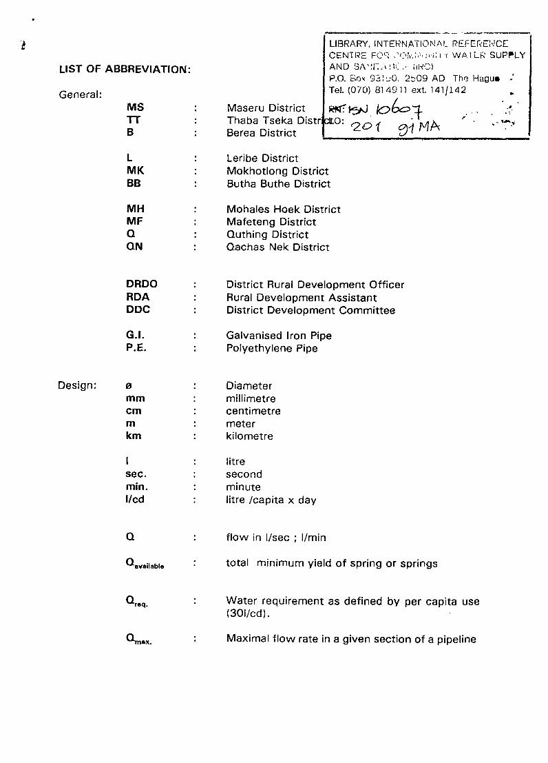
LIST OF ABBREVIATION:
General:MS : Maseru DistrictTT : Thaba Tseka DistrB : Berea District
L : Leribe DistrictMK : Mokhotlong DistrictBB : Butha Buthe District
MH : Mohales Hoek DistrictMF : Mafeteng DistrictQ : Quthing DistrictQN : Qachas Nek District
DRDO : District Rural Development OfficerADA : Rural Development AssistantDDC : District Development Committee
G.I. : Galvanised Iron PipeP.E. : Polyethylene Pipe
Design: ø Diametermm millimetrecm centimetrem meterkm kilometre
litresec. secondmin. minuteI/cd litre /capita x day
Q : flow in I/sec ; I/mm
~avaiIabIe : total minimum yield of spring or springs
~req. : Water requirement as defined by per capita use(301/cd).
LIBRARY, INTERNATIONAL PEFERE’!CECENIRE FO~J’Tv.~~ue~ ï WATLR SUPPLYAND SA’~~~P.O. Box 93~0.2b09 AD The Hagu.Tel. (070) 814911 ext. 141/142
Jk~4~fttO:
20~ ~M1~
~mi~x. Maximal flow rate in a given section of a pipeline
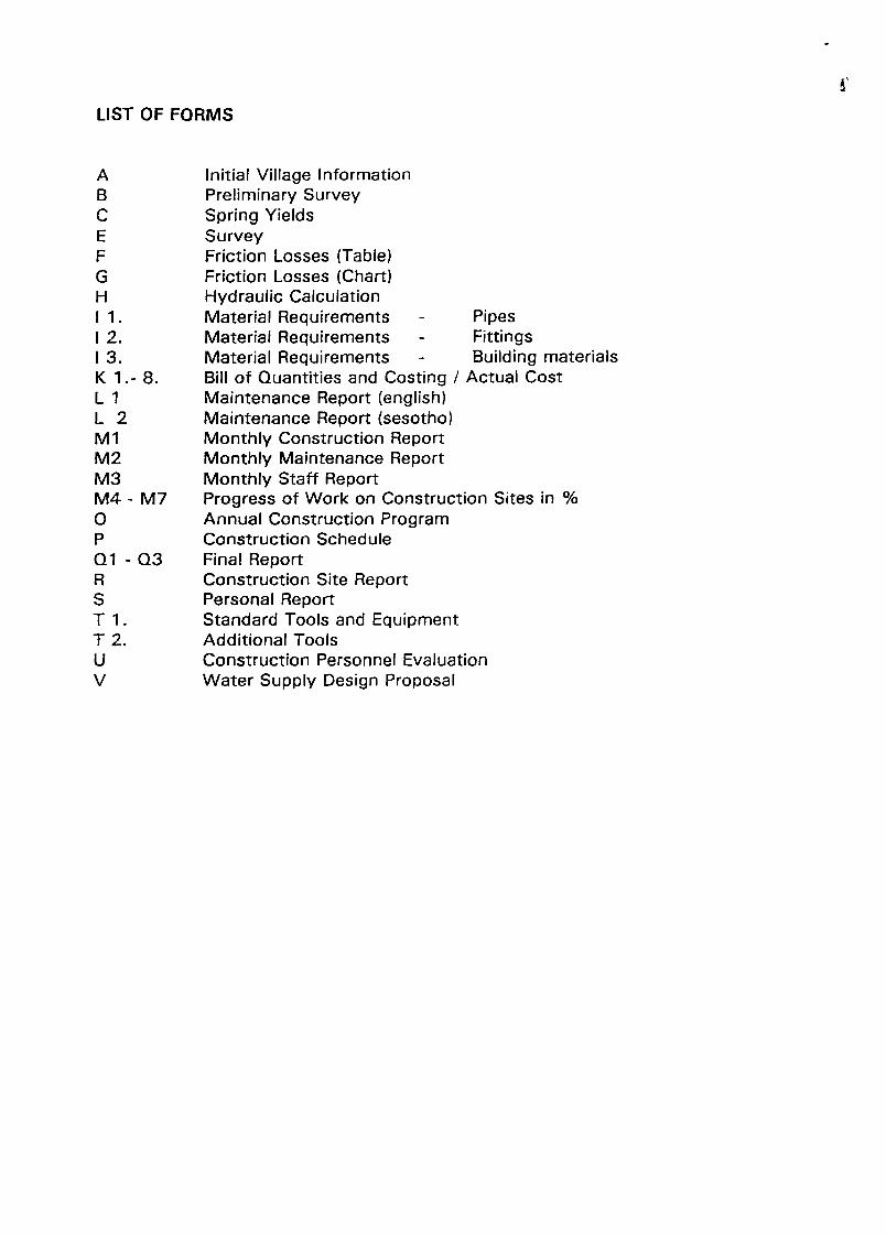
LIST OF FORMS
Initial Village InformationPreliminary SurveySpring YieldsSurveyFriction Losses (Table)Friction Losses (Chart)Hydraulic CalculationMaterial Requirements -
Material Requirements -
Material Requirements -
Bill of Quantities and Costing /Maintenance Report (english)Maintenance Report (sesotho)Monthly Construction ReportMonthly Maintenance ReportMonthly Staff ReportProgress of Work on Construction Sites in %Annual Construction ProgramConstruction ScheduleFinal ReportConstruction Site ReportPersonal ReportStandard Tools and EquipmentAdditional ToolsConstruction Personnel EvaluationWater Supply Design Proposal
ABCEFGHIi.I 2.I 3.K 1.-8.LiL2MiM2M3M4-M7OPQi-Q3RSTi.T2.uV
PipesFittingsBuilding materials
Actual Cost

Pantograph enlargements
Symbols for drawing
Plan title (small)
Plan title (A4)
Load guidelines for trucks
Project proposal - Map 1 : 250’000/50’000
Project proposal - Map 1 : 20’OOO
OF APPENDICES
List of standard plans
LIST
1.
2.
3.
4.
5.
6.
7.
8.
9.
10.
11.
Project proposal
Project proposal
Project proposal
- Layout of site plan
- Example of hydraulic calculation
- Example of technical report
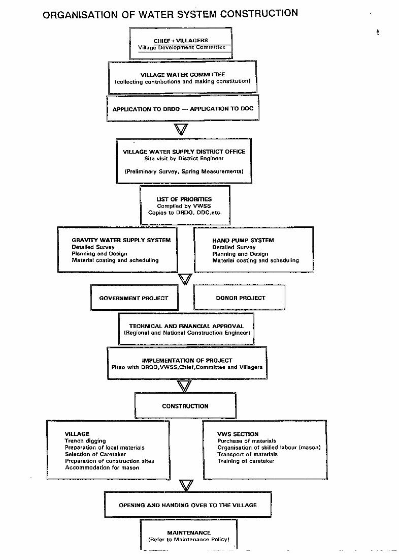
UST OF PRIORITIESCompiled by VWSS
Copies to DRDO. DDC,etc.
GRAVITY WATER SUPPLY SYSTEMDetailed SurveyPlanning and DesignMaterial costing and scheduling
DONOR PROJECT jTECHNICAL AND FINANCIAL APPROVAL
(Regional and National Construction Engineer)
IMPLEMENTATiON OF PROJECTPitso with DRDO,VWSS,Chief,Commlttee and Villagers
t~
VILLAGETrench diggingPreparation of local materialsSelection of CaretakerPreparation of construction sitesAccommodation for mason
MAINTENANCE(Refer to Maintenance Policy)
VWS SECTIONPurchase of materialsOrganisation of skilled labour (mason)Transport of materialsTraining of caretaker
ORGANISATION OF WATER SYSTEM CONSTRUCTION
- CHIEF±VILLAGERS 1Village DeveloPment Commit~J
VILLAGE WATER COMMITFEE(collecting contributions and making constitution)
APPLICATION TO DRDO — APPUCAT1ON TO DDC
VVILLAGE WATER SUPPLY DISTRICT OFFICE
Site visit by District Engineer
(Preliminary Survey. Spring Measurements)
HAND PUMP SYSTEMDetailed SurveyPlanning and DesignMaterial costing and scheduling
GOVERNMENT PROJECT
VCONSTRUCTION
OPENING AND HANDING OVER TO THE VILLAGE
Page 1
1. PRELIMARY SURVEY
The preliminary survey should give all the necessary basic information to the
planning engineer about the project he is going to build. The engineer is
advised to inform all parties involved in the construction of a village water
supply, from this early stage of planning.
A reference number will be issued to the village by the DRDO’s office which
shows the district and which has a separate number for the village
concerned e.g. MS-33.
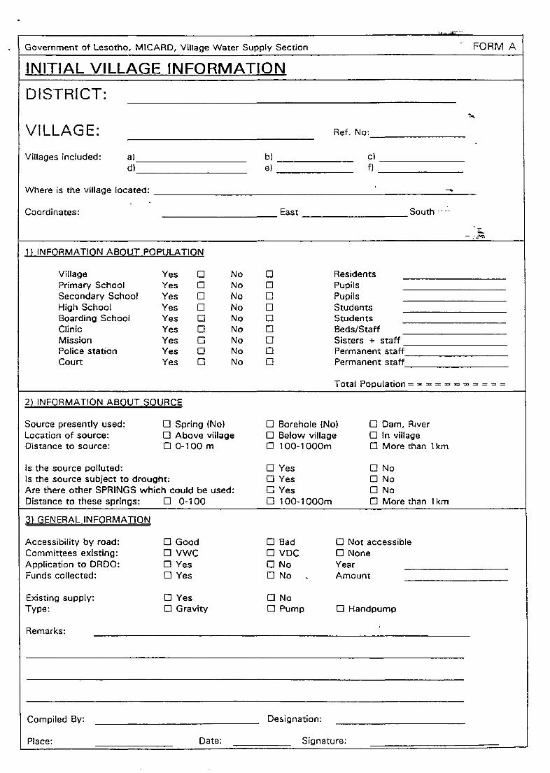
There are three forms available:
Form A: Initial Village Information
This form is used to get information about a village which
cannot be visited by the district engineer in the immediate
future. It can be filled by anybody who is interested in
forwarding information to the Village Water Supply
Section.
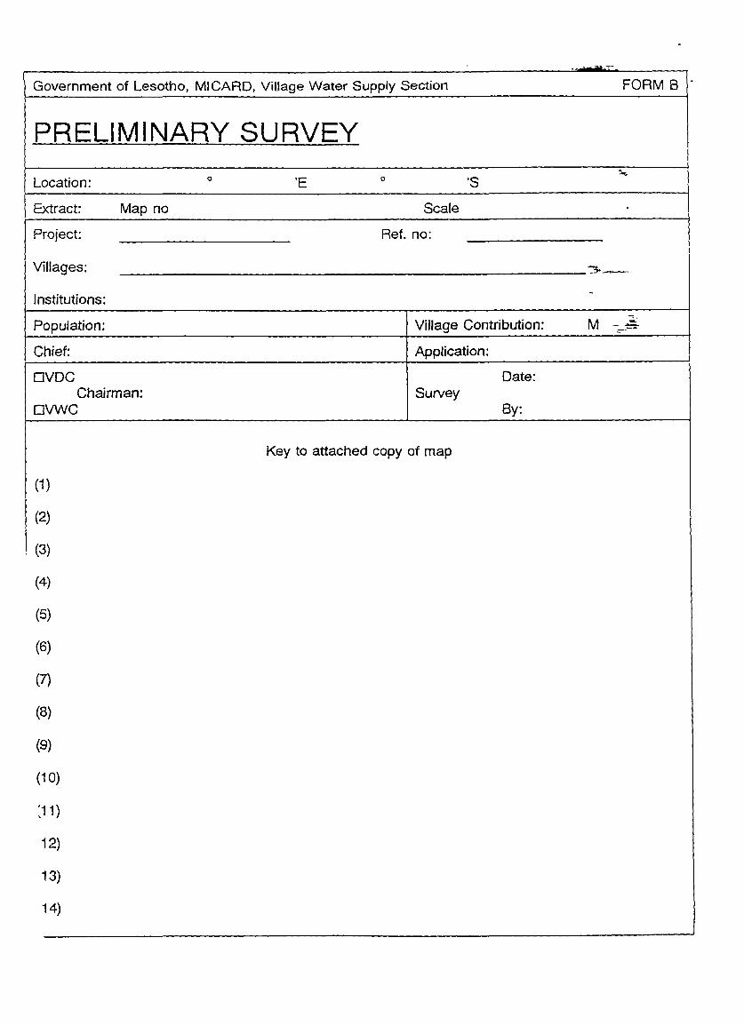
Form B: Preliminary Survey (for internal use only)
This form is used by the District Engineer on his first site visit.
It has to be used together with a copy of a topographic map,
or with a sketch showing the sources, the number of huts and
their scattering over the area to be served by the water supply
system. The map also shows the approximate alignment of
any old existing System.
Estimation of population
A sound population count shall be carried out by the village
water committee. The committee shall list all inhabitants in the
village including children and migrant workers not present
throughout the year.
A rough estimation is done as follow:
Number of huts x 3 inhabitants\hat
Page 2
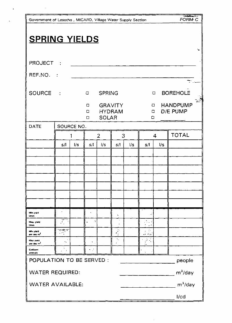
From C: Spring yields
While filling form B, Form C also has to be filled for the first
time. It shows the variable yields of the sources throughout
the year. Spring readings must be taken every three months or
as often as possible to ensure a reliable source. Reliable long
term spring measurements help in the proper design of the
system. Spring readings must be taken in such a way as to
reflect minimum and maximum yield.
Page 3
2. DETAILED SURVEY
2.1. SURVEY METHODS
Normally, the survey is carried out with the following instruments:
Abney level : measuring the vertical angle*
Clino meter : measuring the vertical angle*
Compass : measuring the horizontal angle*
Measuring wheel : measuring the distance between survey points.* Use either 90°or1 00~instruments, uniform in a particular district.
In flat areas where heights are critical, we use a levelling instrument or a
theodolite. Always close the survey with a control measurement in order
to check the accuracy of the survey. During the survey a sketch is
prepared to visualise the survey points, the roads and tracks, the huts and
the special landmarks. The following form is used for compilation of
readings: Form E : Survey.
2.2. GENERAL NOTES
The following points should be considered when making any survey:
Siltbox : as close as possible to the spring catchment
Gradient : between spring catchment and siltbox min. 3%
between siltbox and tank min. 3%
highpoints and lowpoints should be well defined.
Pipeline : keep it as short as possible
Donga crossing : should be placed at the most economical place
and should be well founded and taking account of
future erosion.
Tanks as close as possible to the consumers, to use the
Page 4
most efficient pipe diameter, but preferably more
than 5m above the first tap.
Distribution
No. of taps
place taps on high- and lowpoints (avoid additional
structures)
not more than 1 50m walking distance to the nearest
tap. Exception: if less than 40 consumers, up to
300m walking distance is acceptable).
Placement of private taps: Special cases refer to the
Management Village Water Supply Section.
not more than 1 50 consumers per tap
not less than 40 consumers per tap
Average consumers per tap the village 80 - 120

Page 5
3. DESIGN OF A WATER SUPPLY SYSTEM
3.1. WATER CONSUMPTION
From the preliminary survey use the total population to get the required
amount of water per day. Use the population count list compiled by the
Village Water Committee. To consider the increase of consumption and
the population growth use a demand of 30 I/cd. However local condition
(accessability of springs, growth of village, possibility of drilling) may
require the engineer to accept a system providing less than 30 I/cd.
The following values for institutions have to be considered, if they will be
supplied by a new water supply system:
- Boarding school 60 II student x day
- Ordinary school 2 II pupil x day
- Govt. clinic 100 l/ bed x day
pIus 30 II employee x day
- Dwelling house linked with any
of the above 200 l/ home x day
Special attention has to be given to future plans for Village development
in terms of new schools, clinics, local courts etc.
Page 6
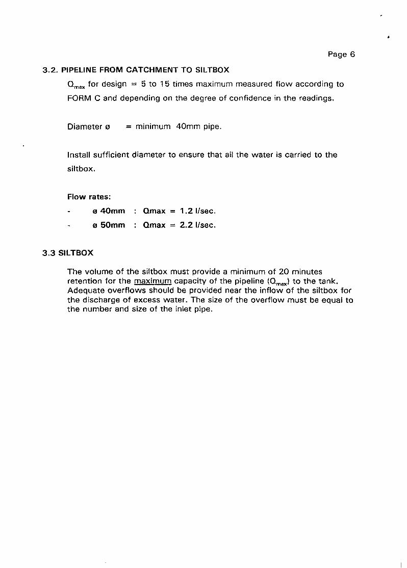
3.2. PIPELINE FROM CATCHMENT TO SILTBOX
~1max for design = 5 to 1 5 times maximum measured flow according to
FORM C and depending on the degree of confidence in the readings.
Diameter ø = minimum 40mm pipe.
Install sufficient diameter to ensure that all the water is carried to the
siltbox.
Flow rates:
3.3 SILTBOX
e 40mm : Qmax = 1.2 I/sec.
e 50mm : Qmax = 2.2 I/sec.
The volume of the siltbox must provide a minimum of 20 minutesretention for the maximum capacity of the pipeline (umax) to the tank.Adequate overflows should be provided near the inflow of the siltbox forthe discharge of excess water. The size of the overflow must be equal tothe number and size of the inlet pipe.

Page 7
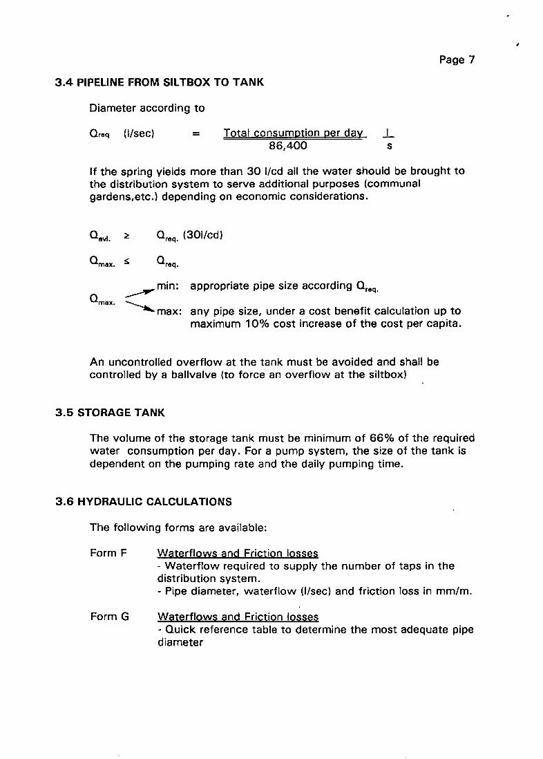
3.4 PIPELINE FROMSILTBOX TO TANK
Diameter according to
Qreq (l/sec) = Total consumøtion ~er day .1
86,400 sIf the spring yields more than 30 I/cd all the water should be brought tothe distribution system to serve additional purposes (communalgardens,etc.) depending on economic considerations.
~1req. (301/cd)
~m5x. ~ ~raq.
mm: appropriate pipe size according ~req.
umax.max: any pipe size, under a cost benefit calculation up to
maximum 10% cost increase of the cost per capita.
An uncontrolled overflow at the tank must be avoided and shall becontrolled by a balivalve (to force an overflow at the siltbox)
3.5 STORAGETANK
The volume of the storage tank must be minimum of 66% of the requiredwater consumption per day. For a pump system, the size of the tank isdependent on the pumping rate and the daily pumping time.
3.6 HYDRAULICCALCULATIONS
The following forms are available:
Form F Waterf lows and Friction losses- Waterflow required to supply the number of taps in thedistribution system.- Pipe diameter, waterfiow (I/sec) and friction loss in mm/m.
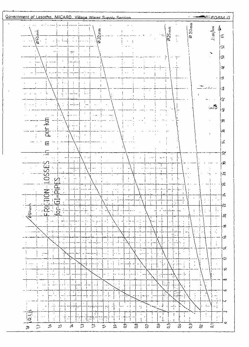
Form G Waterfiows and Friction losses- Quick reference table to determine the most adequate pipediameter
Page 7
3.4 PIPELINE FROM SIITBOX TO TANK
Diameter according to
Qraq (I/sec) = Total consumDtion per day ..L86,400 s
If the spring yields more than 30 I/cd all the water should be brought tothe distribution system to serve additional purposes (communalgardens,etc.) depending on economic considerations.
~req. (301/cd)
umax. � ~req.
appropriate pipe size according ~r.q.
max.max: any pipe size, under a cost benefit calculation up to
maximum 10% cost increase of the cost per capita.
An uncontrolled overflow at the tank must be avoided and shall becontrolled by a bailvalve (to force an overflow at the siltbox)
3.5 STORAGE TANK
The volume of the storage tank must be minimum of 66% of the requiredwater consumption per day. For a pump system, the size of the tank isdependent on the pumping rate and the daily pumping time.
3.6 HYDRAULIC CALCULATIONS
The following forms are available:
Form F Waterflows and Friction losses- Waterfiow required to supply the number of taps in thedistribution system.- Pipe diameter, waterflow (1/sec) and friction loss in mm/rn.
Form G Wpterflows and Friction losses- Quick reference table to determine the most adequate pipediameter

Page 8
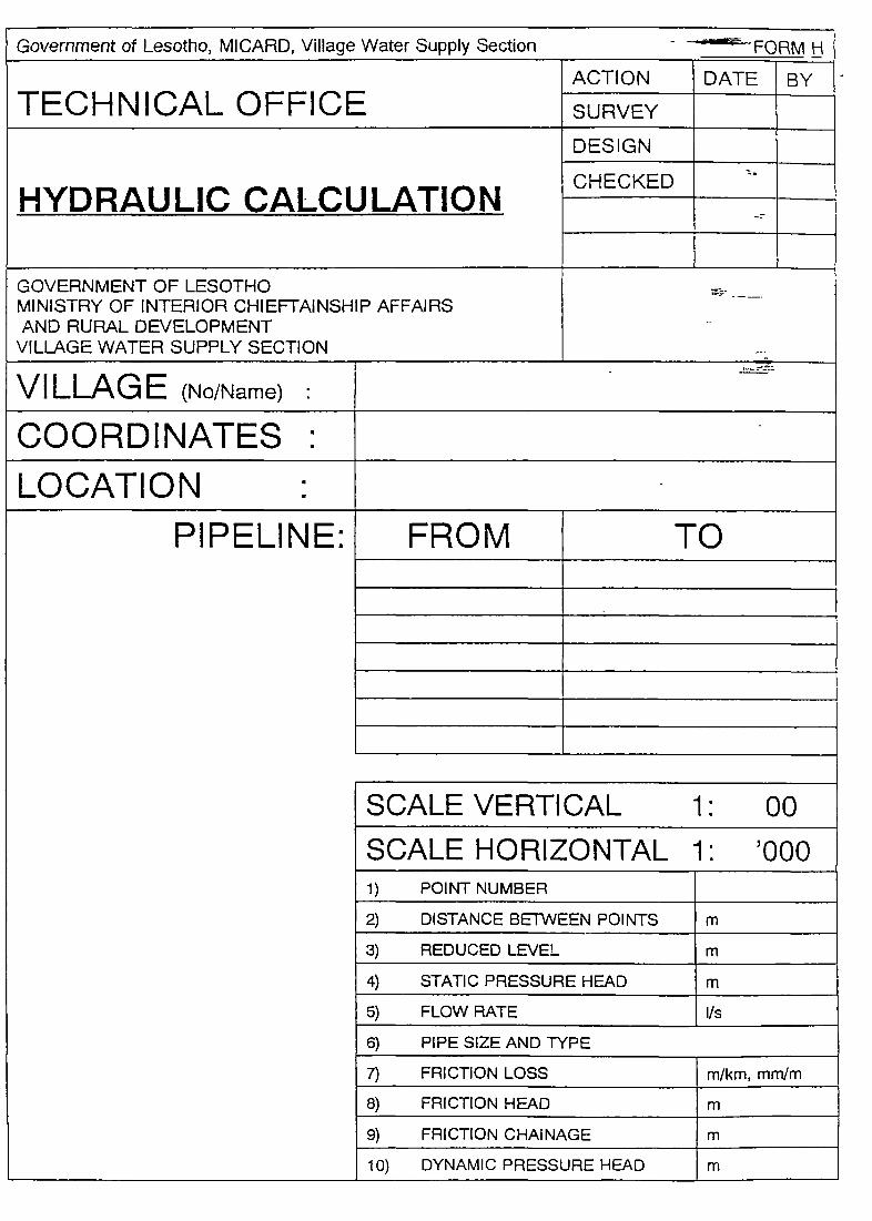
Form H Hydraulic calculation
This is used for the calculation and drawing of thelongitudinal section of the pipeline to find a reasonable pipesize, (not to make sure that every tap will be supplied withthe theoretical amount of 0.2 I/sec.)
Line 1 : Survey point number according toForm E and the site plan. -
Line 2 : Horizontal distance between survey points inmeters (m).
Line 3 : Reduced level according to the heightscalculated in Form E in meters (m).
Line 4 : Static pressure head is the difference in level(m) between the previous free water surface(spring, siltbox, pressure break tank, storagetank) and the level at the specific point.
Line 5 : Flow in I/sec can be obtained from Form F, fromsection 3.2 and 3.6.
Line 6 : Pipe size and type (e.g. GI 20mm)
Line 7 : Friction losses in rn/km are read from Form Fand G. These figures include an additional 10%for friction of fittings and progressive roughnessof used pipes.
Line 8 : Friction head for each pipe section is foundmultiplying line 2 x line 7 (length x friction perlength). Use consistent units (e.g. km andrn/km or m and mm/rn).
Line 9 : Friction chainage is obtained by adding all thefriction heads (line 8), starting from the pointwith free waterlevel to each specific point.
Line 10 : Dynamic pressure head is the differencebetween the static pressure head and thefriction chainage (L4-L9).
** Always indicate the maximum capacity ofthe pipeline between siltbox and tank on thehydraulic profile sheet.
Page 9
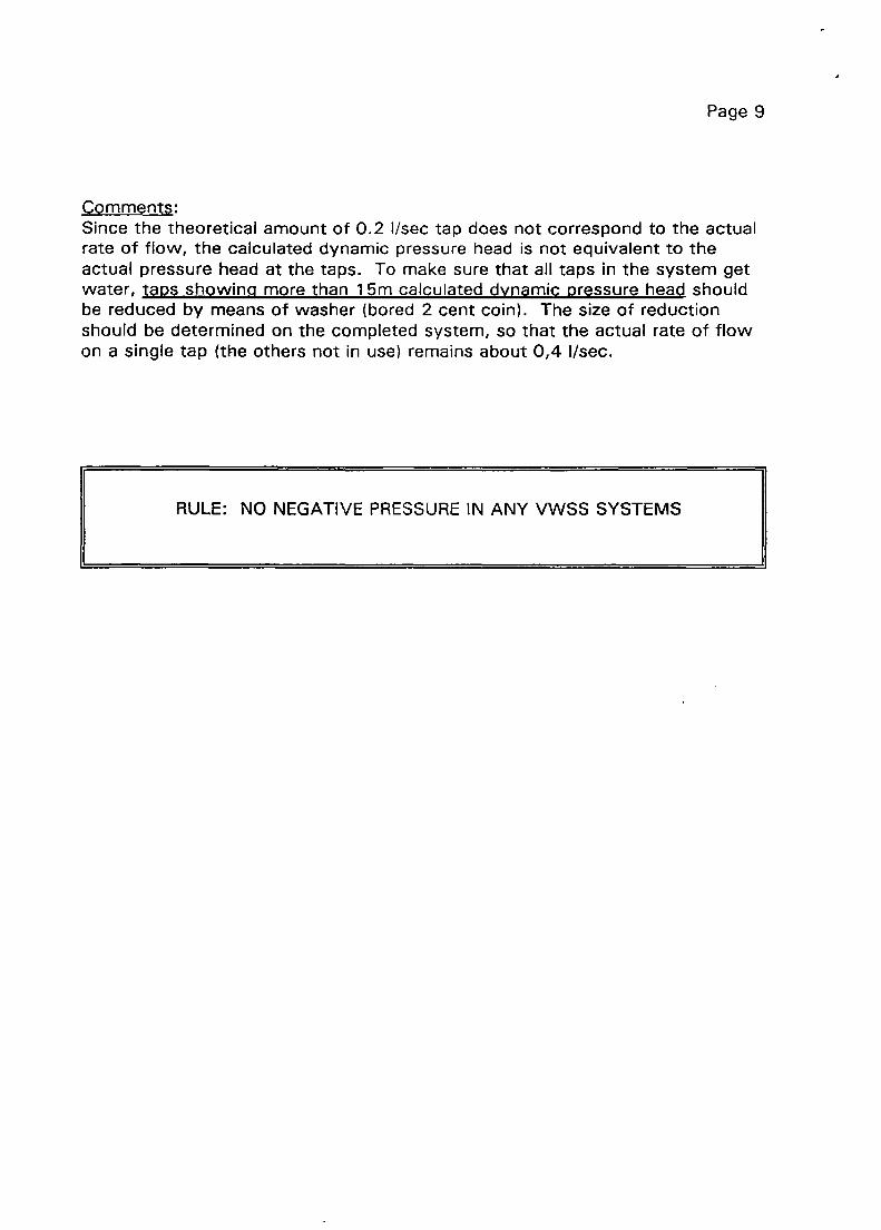
Comments:Since the theoretical amount of 0.2 I/sec tap does not correspond to the actualrate of flow, the calculated dynamic pressure head is not equivalent to theactual pressure head at the taps. To make sure that all taps in the system getwater, taos showing more than 1 5m calculated dynamic pressure head shouldbe reduced by means of washer (bored 2 cent coin). The size of reductionshould be determined on the completed system, so that the actual rate of flowon a single tap (the others not in use) remains about 0,4 I/sec.
RULE: NO NEGATIVE PRESSURE IN ANY VWSS SYSTEMS

GOVERNMENTOF LESOTHO
MINISTRY OF INTERIOR, CHIEFTAINSHIP AFFAIRSAND RURALDEVELOPMENT
VILLAGE WATERSUPPLY
HA MOKOTJELA WATER SUPPLY
PLAN SCALE 1: 5000
31 km east cl Butha Buthe Camp
28 37 S/ 28~31 E1870 m above sea level
2828 DA1 I 1: 20000
SURVEY
DESIGN
DRAWN
CHECKED
AS BUILD
Situated
Coordinates
Map Sheet
r—-- --
TECHNICAL OFFICE BUTHA BUTHE ACTION
SITE PLAN
BB-

Page 11
- Keys and mixing ratios
- Plan of the structure, scale 1 : 20
- Required sections, usual scale 1 : 20
Refer to APPENDIX I of this manual for the list of available standard
plans. On special request there is a list showing plans for standard
structures built from 1978 to 1983 and special structures (see VWSS
library).
5. COMPILING LIST OF MATERIAL AND COSTS
The following forms are available:
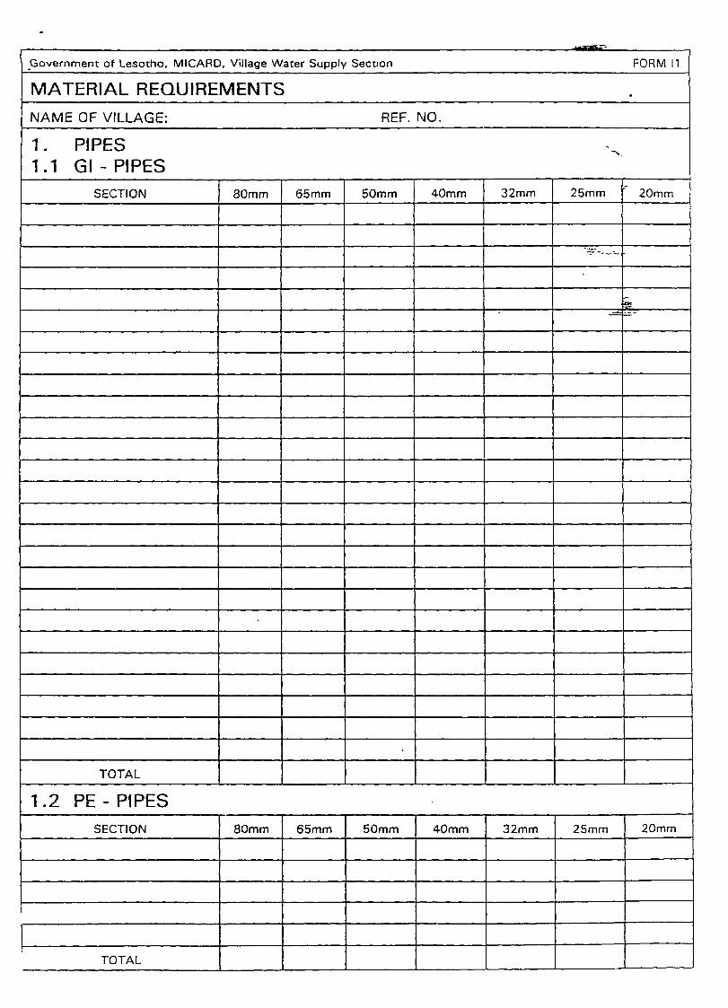
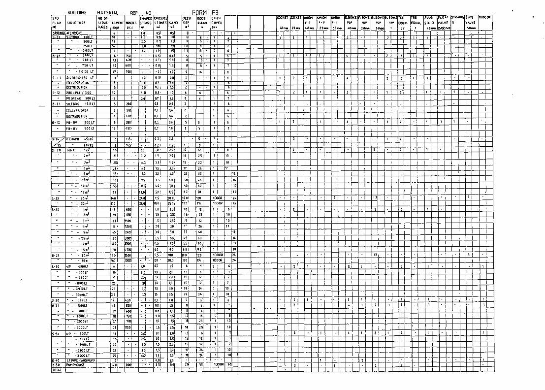
Form I MATERIAL REQUIREMENTS
I 1 PIPES for compiling the required amount of GI - or PE-
pipes for one project.
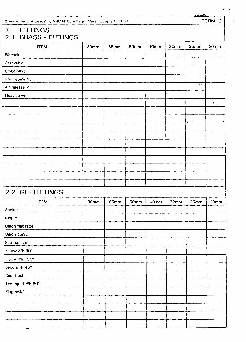
I 2 FITTINGS for compiling the required amounts of GI -
and PE-fittings for all the structures and pipelines.
Depending on the alignment, additional elbows or
bends are necessary for changes of gradient and
direction.
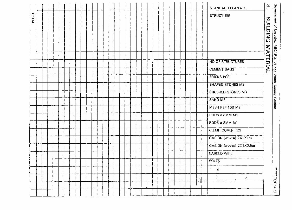
I 3 LOCAL MATERIAL for all structures. For donga
crossings and other protective structures, additional
cement, sand, crushed stones and stones should be
added.
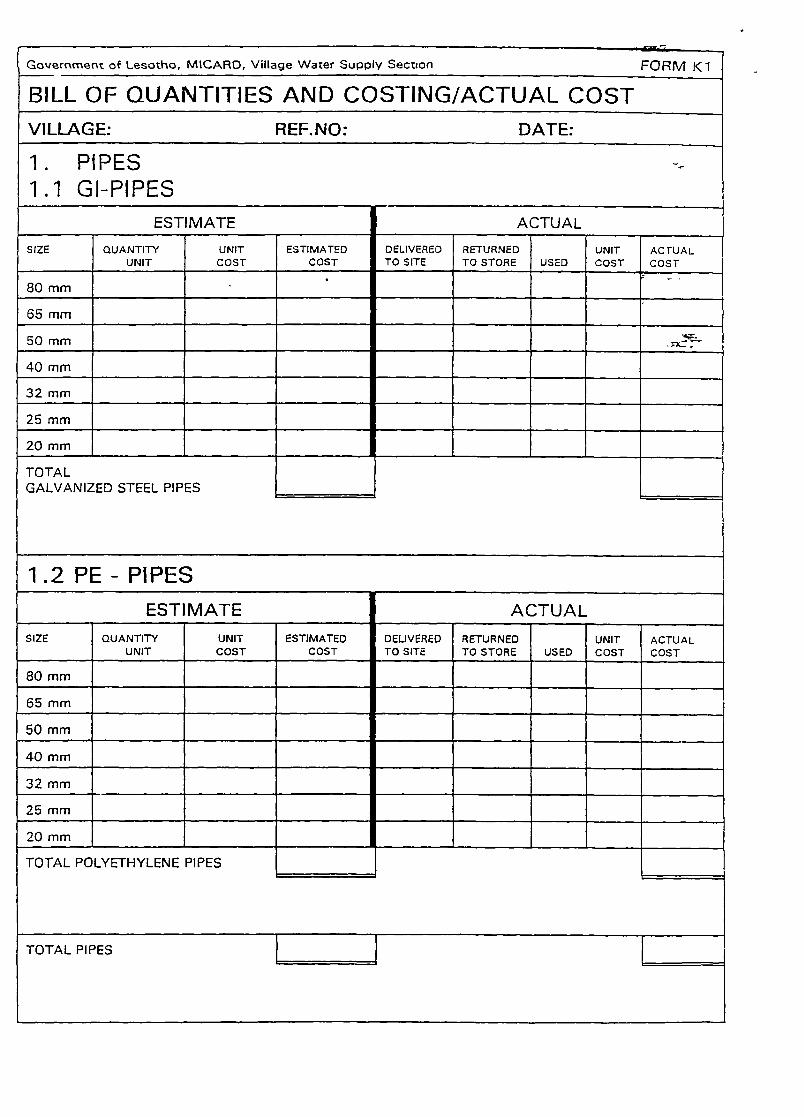
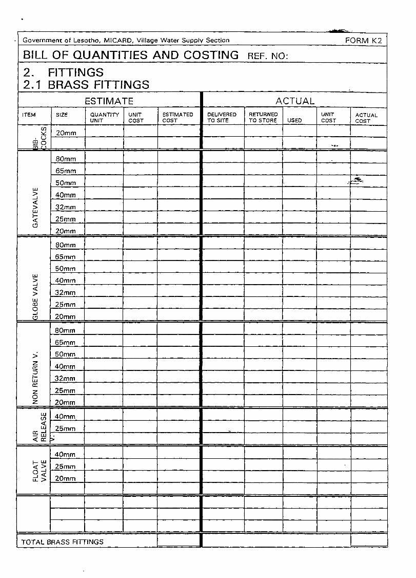
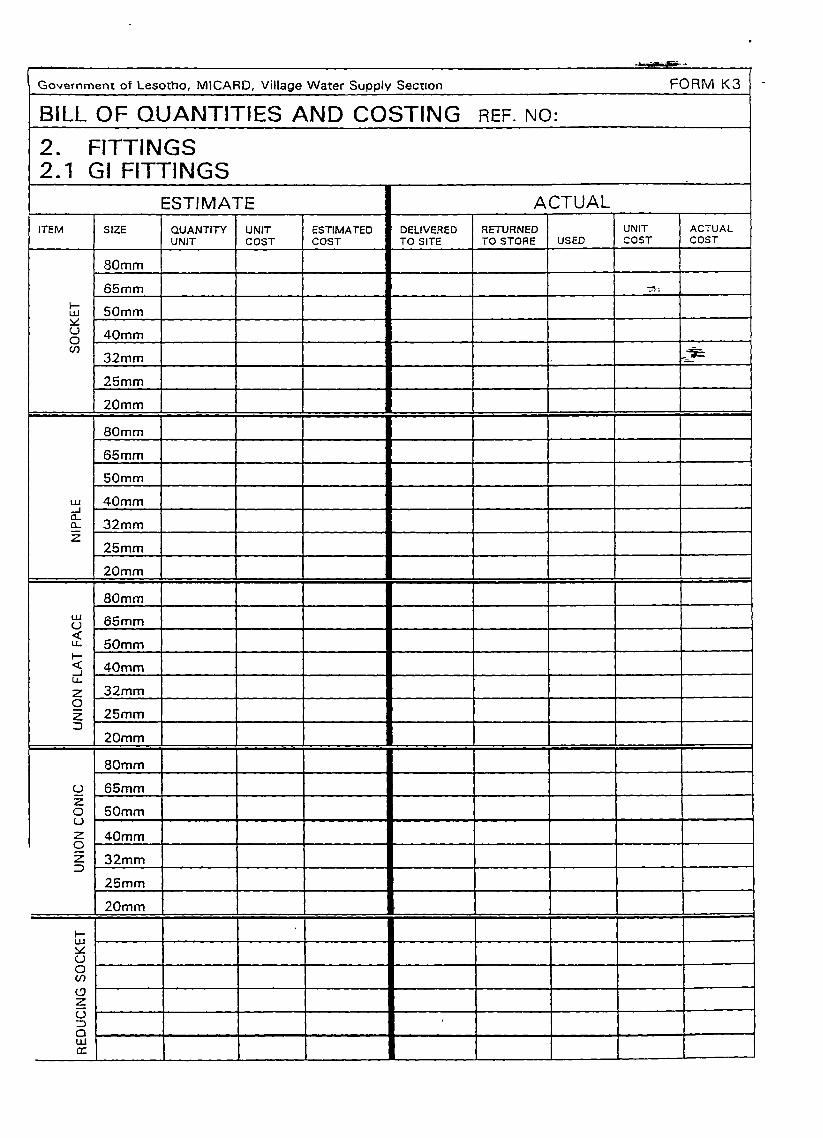
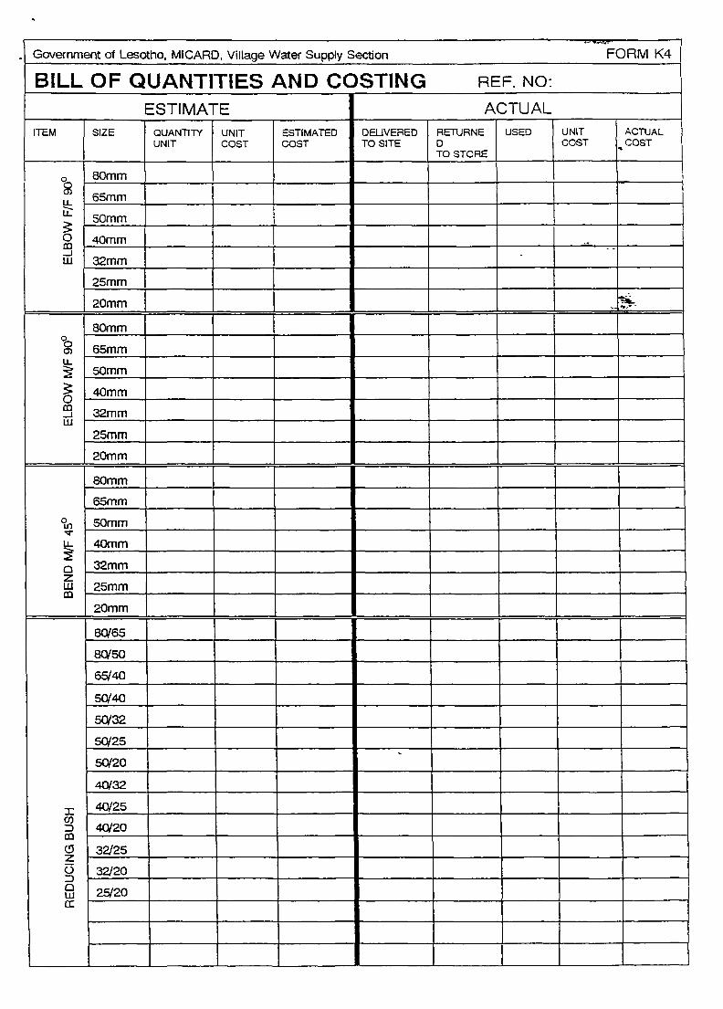
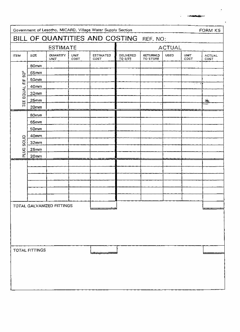
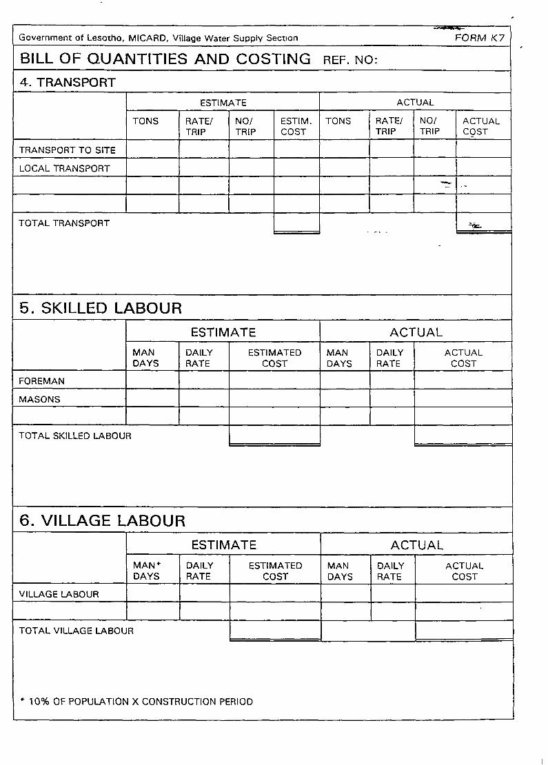
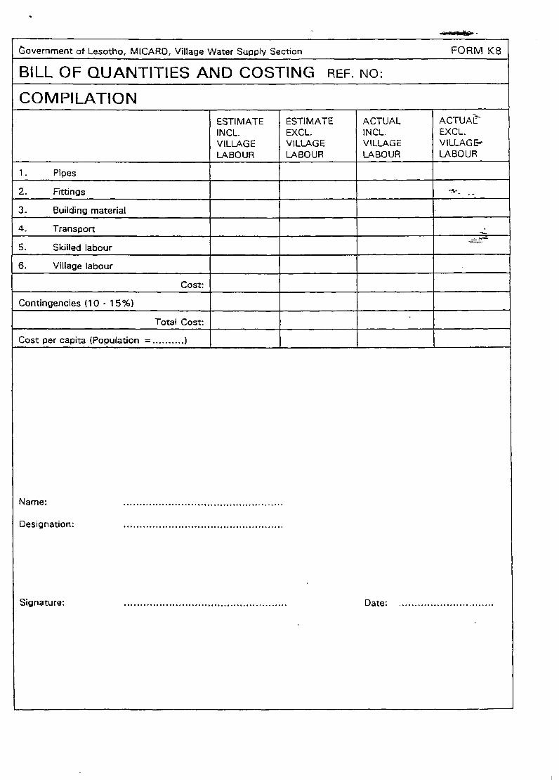
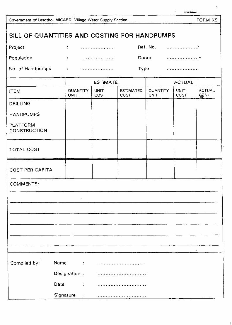
Form K BILL OF QUANTITIES AND COSTING/ACTUAL COST.
This is used for compiling the costs of pipes, fittings,
local material, transport and skilled labour. It is used
also for compiling the actual costs of the project.
The compiled quantities from Forms Il, 12 and 13 have
to be transferred to the correct column on Form K.
To get the final costs the current price list has to be
used.
Page 12
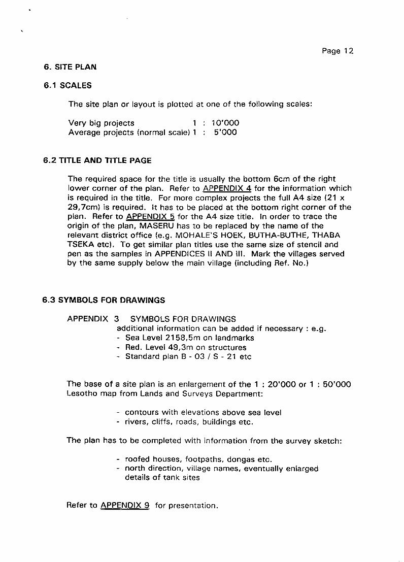
6. SITE PLAN
6.1 SCALES
The site plan or layout is plotted at one of the following scales:Very big projects
Average projects (normal scale) 1
6.2 TITLE AND TITLE PAGE
10’OOO
5’OOO
The required space for the title is usually the bottom 6cm of the rightlower corner of the plan. Refer to APPENDIX 4 for the information whichis required in the title. For more complex projects the full A4 size (21 x29,7cm) is required. It has to be placed at the bottom right corner of theplan. Refer to APPENDIX 5 for the A4 size title. In order to trace theorigin of the plan, MASERU has to be replaced by the name of therelevant district office (e.g. MOHALE’S HOEK, BUTHA-BUTHE, THABATSEKA etc). To get similar plan titles use the same size of stencil andpen as the samples in APPENDICES il AND III. Mark the villages servedby the same supply below the main village (including Ref. No.)
6.3 SYMBOLS FOR DRAWINGS
APPENDIX 3 SYMBOLS FOR DRAWINGSadditional information can be added if necessary : e.g.- Sea Level 2158,5m on landmarks- Red. Level 49,3m on structures- Standard plan B - 03 / S - 21 etc
The base of a site plan is an enlargement of the 1 : 20’OOO or 1 : 50’OOOLesotho map from Lands and Surveys Department:
- contours with elevations above sea level
- rivers, cliffs, roads, buildings etc.
The plan has to be completed with information from the survey sketch:
- roofed houses, footpaths, dongas etc.- north direction, village names, eventually enlarged
details of tank sites
Refer to APPENDIX 9 for presentation.
Page 13
6.4 LONGITUDINAL SECTIONS
These are drawn for the hydraulic calculation only, and are not part of theplan.Use FORM H for plotting
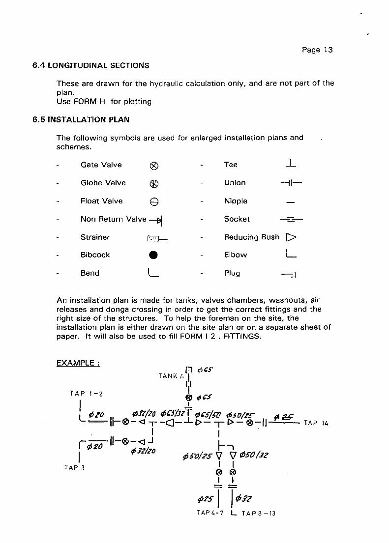
6.5 INSTALLATION PLAN
The following symbols are used for enlarged installation plans andschemes.
Gate Valve
Globe Valve
Float Valve GNon Return Valve
Strainer
Bibcock .
- Tee
- Union
- Nipple
- Socket
H!—
- Reducing Bush >- Elbow L
An installation plan is made for tanks, valves chambers, washouts, airreleases and donga crossing in order to get the correct fittings and theright size of the structures. To help the foreman on the site, theinstallation plan is either drawn on the site plan or on a separate sheet ofpaper. It will also be used to fill FORM I 2 . FITTINGS.
EXAMPLE:
TAP 1—2
L ~ 01,/jo__II_ø_11
rØ2’O Ø12/!O
TAP 3
flç~CFTANK A
Il
~�C5/JzT~c~/.coc~cz’/:r Ø z.c_~_Lt~_m~~_®_II_ TAP 14
Ø~O/2SV V 03-0/32I I
-i-j-
TAP4-7 L TAP 8—13
Bend L - Plug -J

Page 14
7. SELECTION OF PUMP AND ENGINE
A) Surveying of local conditions
- Level pump - tank Static head
- Diameter of pipe Dynamic head
- Yield of spnng / pump test of borehole
- Storage beside the pump house
- Availability of electricity
B) Selecting the most effective and economic combination: (Running
costs and maintenance costs)
- Diesel drive - Borehole pump
- Horizontal pump
- Electric drive - Horizontal pump
- Submersible pump
- Solar - Submersible and
surface pumps.
C) Calculation and dimensioning are done on a separate sheet. There
is a counter-check made by the maintenance engineer and/or by the
supplier.
D) Design details are:
- Daily pumping time:
- 8 to maximum 10 hours for diesel engines.
- 1 2 hours maximum for electric pumps.
Control system on electric pump systems:
- Float switch
- Low water cut off.
REFERTO ENGINEERSHANDBOOK/PUMP DESIGN
Page 15
8. CONSTRUCTION DETAILS
8.1 DEPTH OF TRENCHES
The depth of trenches should be
- Through fields 1,0 metre
- - Through pastures 0,6 metre
- For road crossings 1 ,0 metre
- On rock, the pipe should be protected with a dry stone
wall and packed in soil, or it can be carried on pillars
(masonry or steel).
When crossing roads, liaise with Roads Department. A GI pipe is used as
a sleeve protecting the water carrying pipe. The minimum diameter of
this pipe is 50mm. If using a culvert, the pipe should run on the roof.
8.2 DETAILS OF STRUCTURES
Refer to APPENDIX I , to the standard plans and to the special file on
building construction. (Foreman- and Supervisor Course Manuals)
9. REPORT SYSTEM
9.1. REPORTS FILLED IN BY DESSTO’S ORSUPERVISORS
9.11. TECHNICAL REPORT
This report, compiled and signed by the District Engineer, is a component
of the project file for each project built or supported by VWS - Section
and has to be included in the file for approval by the Regional Engineer.
(see also chapter 10) The following sections must be included:
A~ INTRODUCTION: When was the application made? Where is thevillage situated? Is there only one village or
several small ones? Are there other rural
development projects already going on?
POPULATION: Give the populations of sub villages.
Page 16
Is it a growth area or not?
Are there already plans to extend the village?
_________ What sources are available, give
locations? Who owns them? What is the yield
(I/mm.) Amount of water available (m3/day;
I/day) Amount of water required (m3/day with
30 I/cd). Specify maximum and minimum yield.
Attach Form D Spring Yields
Pipe material, building material. Structures to be
build (Standards). Outline of the pipeline.
(Topo-graphical problems etc.)
f!. COSTING: Material, transport, labour. Give the expected
village contribution if possible. Total cost and
cost per capita.
E~. CONSTRUCTION SCHEDULE:Starting date, duration, manpowerrequired, completion date.
~ FINAL OBSERVATION: Personal remarks, about expected
improvements in the water supply situation,
health etc. Comments about maintenance etc.
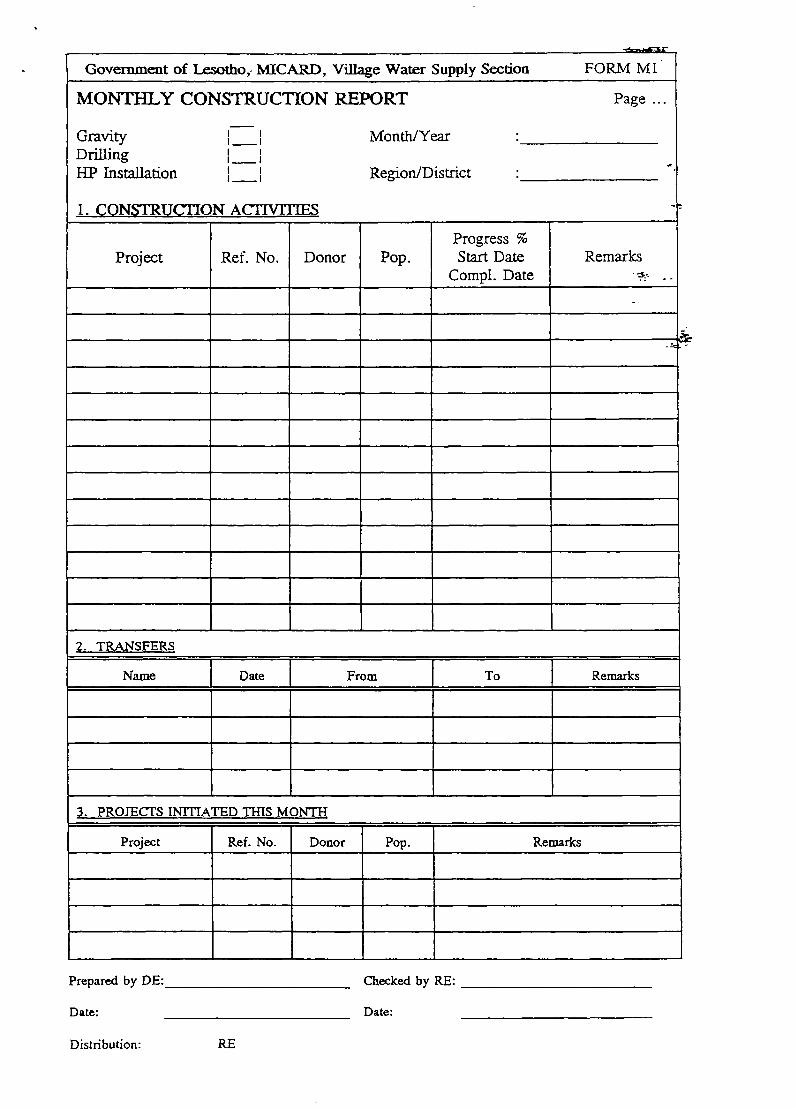
9.1.2. MONTHLY CONSTRUCTION REPORT FORM Ml
Paragraph 2.Transfers shall cover all the movements from projects to
projects as well as transfers from districtto district. The form is
submitted to the Regional Engineer at the end of each month but latest by
the 10th day of the following month.
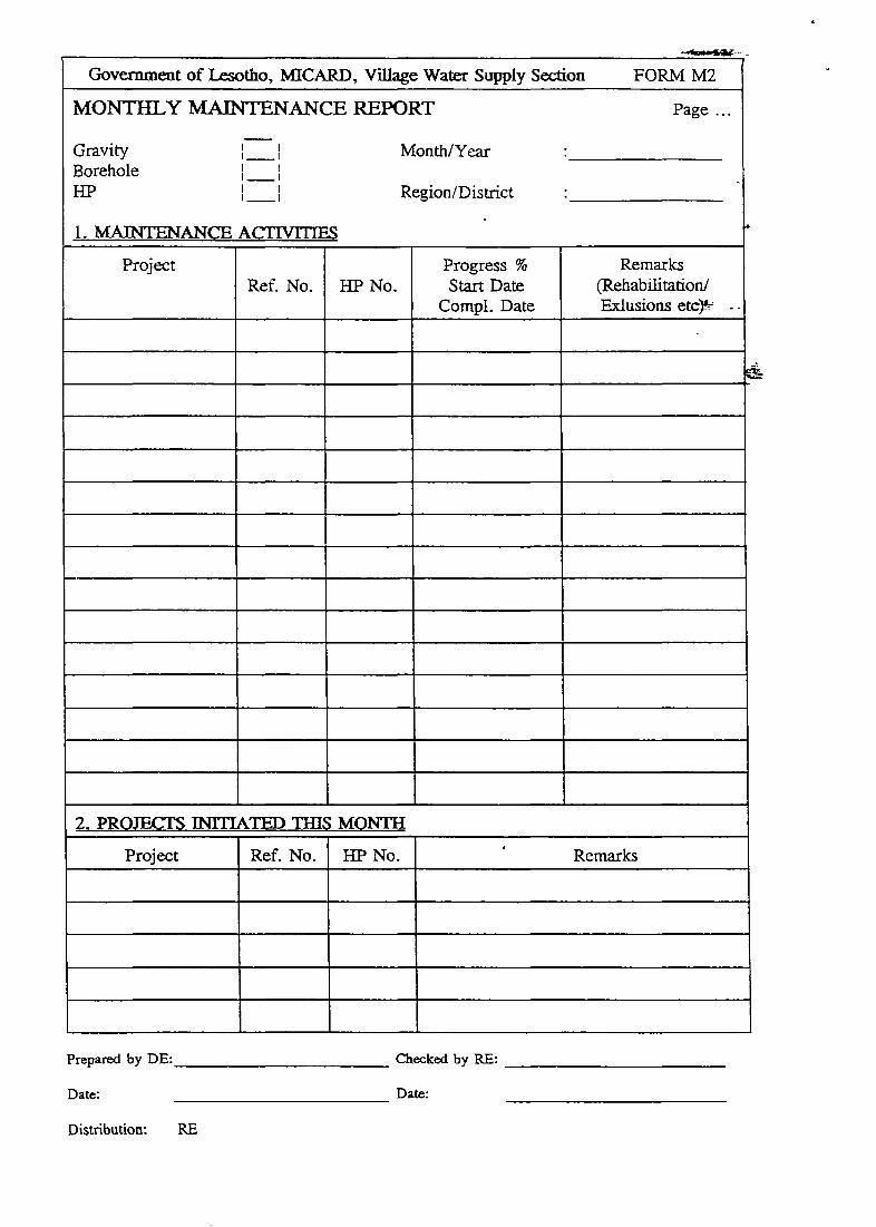
9.1.3. MONTHLY MAINTENANCE REPORT FORM M2
The form is submitted to the Regional Engineer at the end of each month
but latest by the 10th day of the following month, together with the
SOURCES:
fl~ DESIGN:

Page 17
Monthly Construction Report Ml and the Monthly Staff Report M3.
9.1.4. MONTHLYSTAFF REPORT FORM M3
The form is submitted to the Regional Engineer at the end of each month
but latest by the 10th day of the following month, together with the
Monthly Construction Report Ml and the Monthly Maintenance Report
M2. Please note that the Monthly Staff Report Form is for the following
pay day.
9.1.5. PROGRESS OF WORK SITES IN % FORM M4 - M7
Progress of all kinds of construction must be reported. Gravity-, Hand
Pump- Maintenance-, and Rehabilitation Projects. The forms are
submitted to the Regional Engineer at the end of each month but latest by
the 10th day of the following month.
The regional engineer submits a quarterly summary of all activities to the
National Construction Engineer.
9.1.6. FINAL REPORT FORM Qi, Q2, Q3
Final reports must be submitted with the Quarterly Report for the period
in which the project was completed. A site plan “as built” has to be
attached to the report, as well as a copy of the map 1:20,000/1:50,000
with all the information required to keep the central maps in Maseru up
to-date. The Final Report including the “as built” plan must reach the
Regional Engineer 2 months after the Qroject has been completed.
9.1.7. CONSTRUCTION PERSONNEL EVALUATION FORM U
This form must be filled by end of the year or if a transfer from one
district to an other materializes. The evaluation/interview is conducted by
the District Engineer in the presence of the Supervisor/ Senior Technical
Officer and Technical Officer..

Page 18
9.1.8. ANNUALCONSTRUCTIONPROGRAMFORM O
A working tool to plan and monitor the construction activities throughout
the year.
9.1.9. CONSTRUCTION SCHEDULE FORM P
9.1.10. ANNUAL REVIEW AND WORKPLAN FOR THE FOLLOWINGYEAR
Each year the PME Coordinator will propose a format and announce the
date for submission.
9.2. REPORTSBY FOREMANANDMASONS
9.2.1. CONSTRUCTIONSITE REPORTFORM R
- To be collected at payday -
This report is about activities on the site. Presence of foreman, masons
and community (how many villagers). Stock control of cement. This
form has to be filled in by the foreman daily, and checked and signed by
the supervisor and the chairman of the committee.
9.2.2. PERSONALREPORTFORMS
- To be collected at payday -
The personal report must be kept by the foreman and masons daily. The
mason’s report will be signed by the foreman and the foreman’s report
will be signed by the supervisor.
9.2.3. STANDARD TOOLS AND EQUIPMENT FORM Ti
This list has to be filled in by the Storekeepers when they issue tools to
the masons or foreman. This form will be kept by the district engineer.
Whenever tools or equipment have to be replaced, the person concerned
must present the list to stores to enter exchanges. The item/tool to be
replaced must be returned to the storekeeper.
The person who receives the tools and equipment in the first place must

Page 19
sign. When the items are returned to the store, the Storekeeper has to
sign.
9.2.4. ADDITIONAL TOOLSFORMT 2
The same applies to this form as to form T 1
- Additional tools remain the property of the district not the foreman
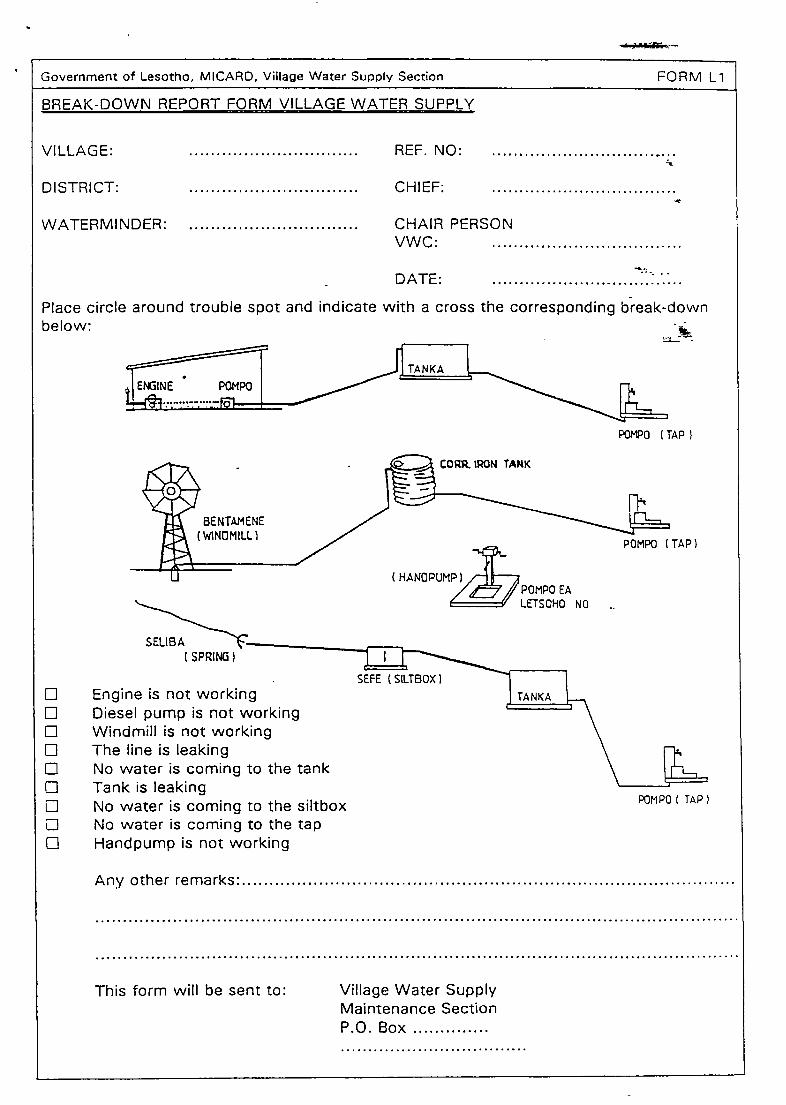
9.3. MAINTENANCEREPORTFORMLi + L2
This form is available in English Li and Sesotho L2. It has to used by the
villages whenever they need VWS maintenance. Forms will be kept by
the DRDO’s office. One copy together with the maintenance job-card has
to be submitted to the district engineer concerned.
The district engineer is responsible for the adequate filing of all the forms.
10. FILING SYSTEM
10.1 CONSTRUCTIONFILE
The district engineer keeps a file with all important forms, plans, notes
etc. for example:
- FormsA-V
- Locational map 1 :50’OOO/l :20’OOO
- Site plan 1:5’OOO
- Technical report etc.
10.2 FILE FOR APPROVAL FORM V
This file has to be submitted to the RE and the NCE for approval and must
contain:
- Map of Lesotho 1 :250’OOO (photocopy of the relevant part
only).
- Locational map 1 :50’OOO/l :25 000/1:20 000
- Site plan l:5’OOO
- Hydraulic calculation

4
Page 20
- Technical report
- Bill of qualities and costing
- Spring gauging
After completion the final report and the site plan “as built” have to be
added, as well as the map 1 :20’000/50’000 as mentioned under 9.1.6.
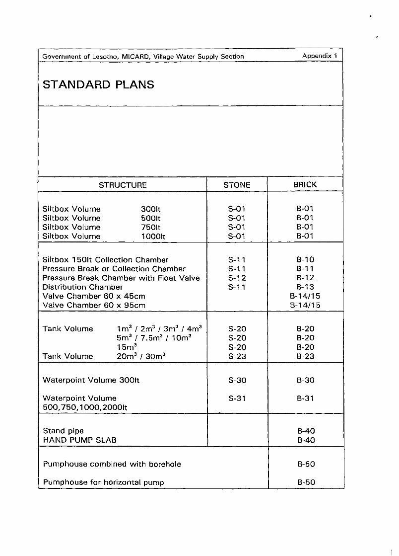
Government of Lesotho, MICARD, Village Water Supply Section Appendix 1
STANDARD PLANS
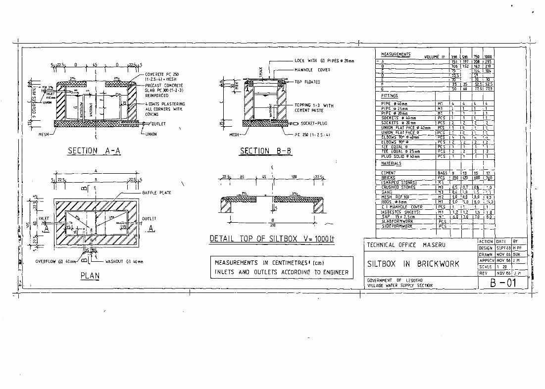
STRUCTURE STONE BRICK
Siltbox Volume 3001tSiltbox Volume 500ltSiltbox Volume 7501tSiltbox Volume l000lt
S-01S-01S-01S-01
B-01B-01B-01B-01
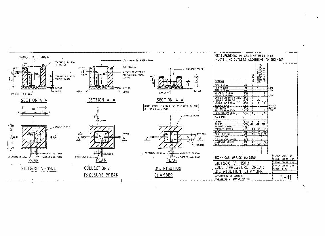
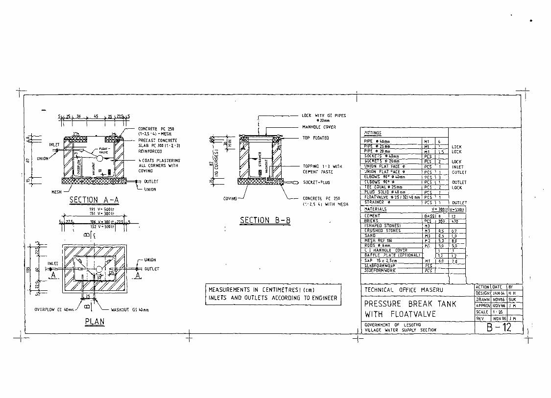
Siltbox 1501t Collection ChamberPressure Break or Collection ChamberPressure Break Chamber with Float ValveDistribution ChamberValve Chamber 60 x 45cmValve Chamber 60 x 95cm
S-11S-1 1S-12S-11
B-10B-1 1B-12B-13
B-14/15B-14/15
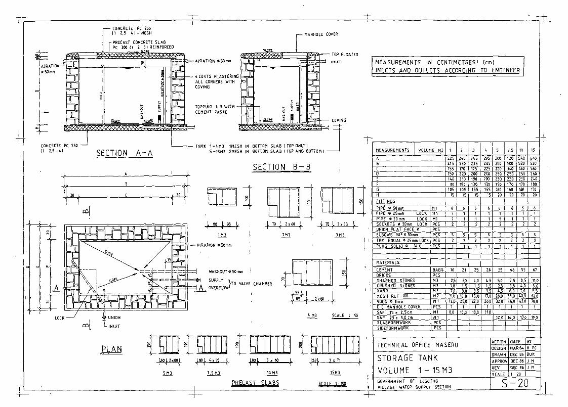
Tank Volume 1m3 / 2m3 / 3m3 / 4m35m3 I 7.5m3 / 10m315m3
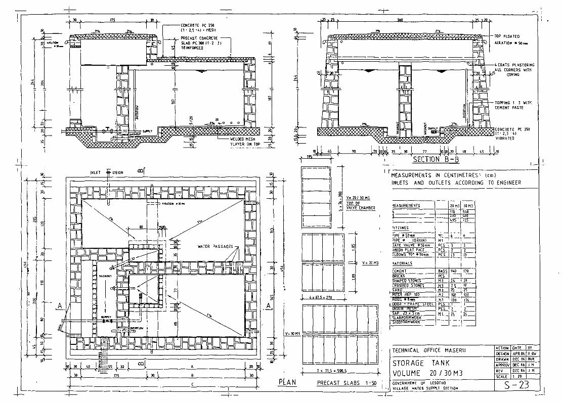
Tank Volume 20m3 / 30m3
S-20S-20S-20S-23
B-20B-20B-20B-23
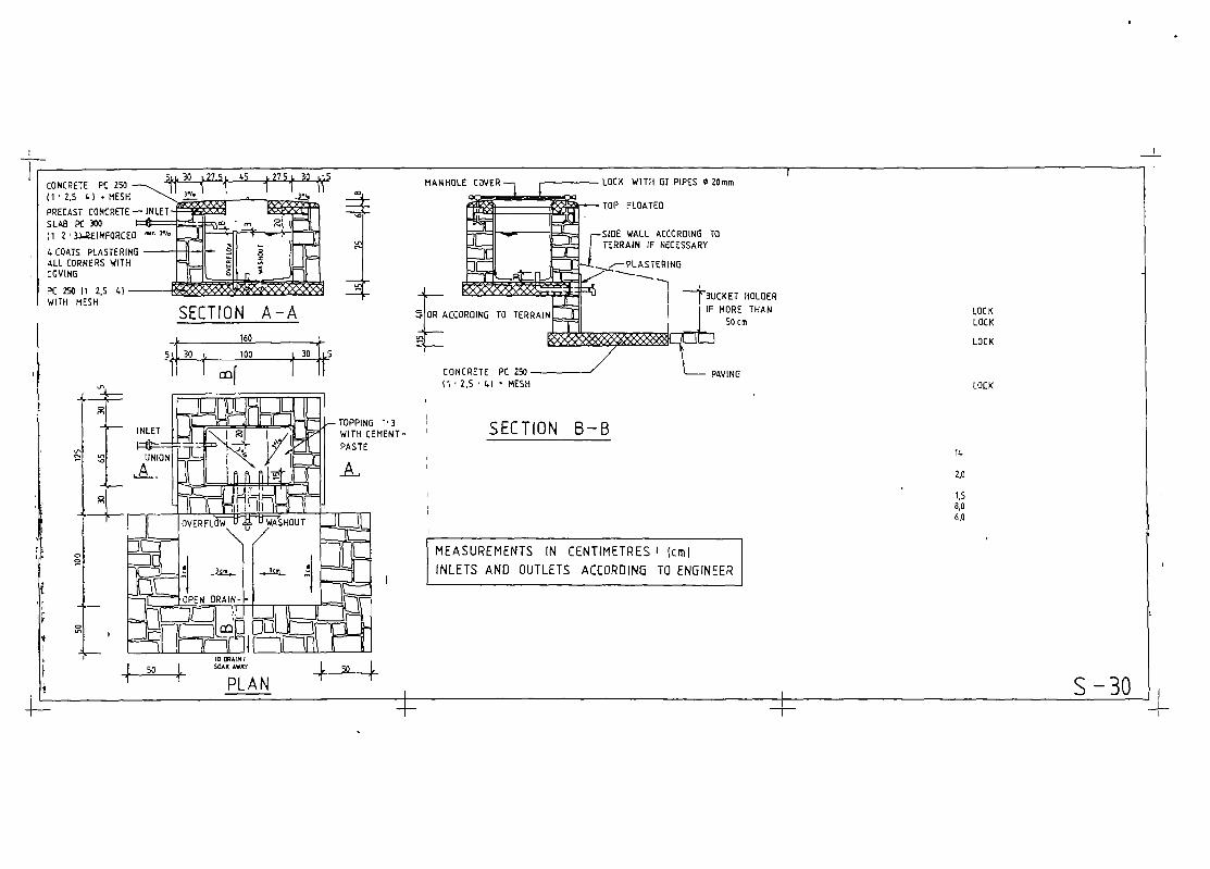
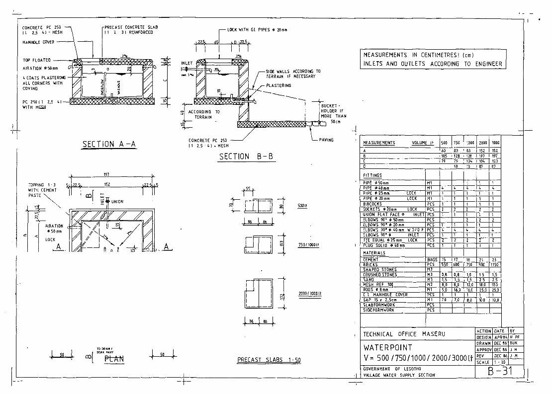
Waterpoint Volume 3001t
Waterpoint Volume500,750,1000,2000lt
S-30
S-31
B-30
B-31
Stand pipeHAND PUMP SLAB
B-40B-40
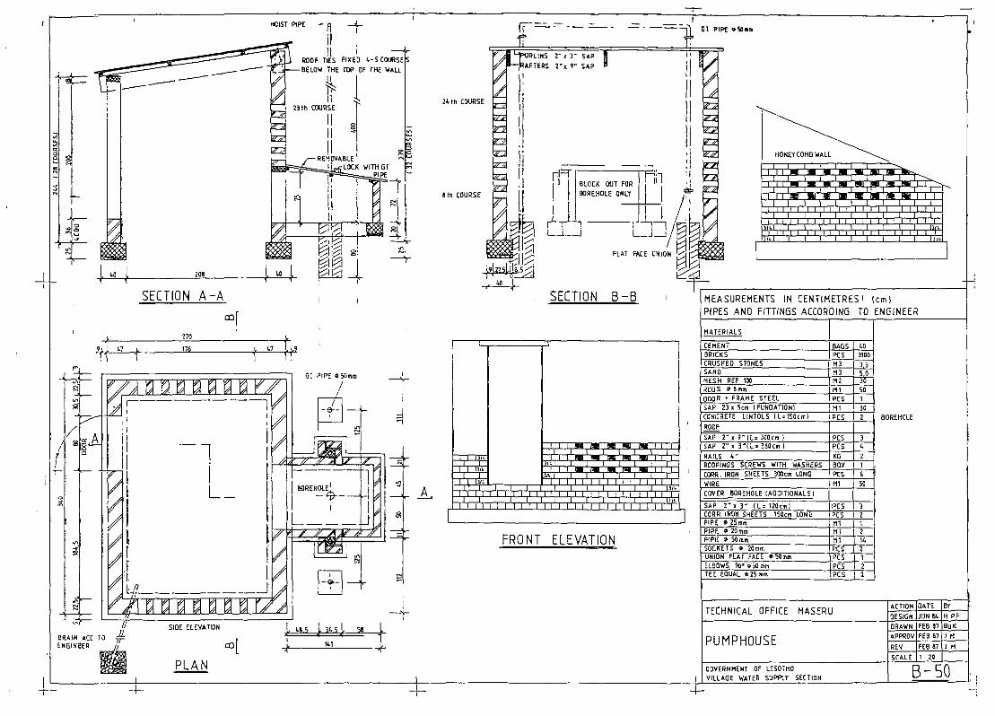
Pumphouse combined with borehole
Pumphouse for horizontal pump
B-50
B-50
t
Government of Lesotho, MICARD, Village Water Supply Section APPENDIX 2
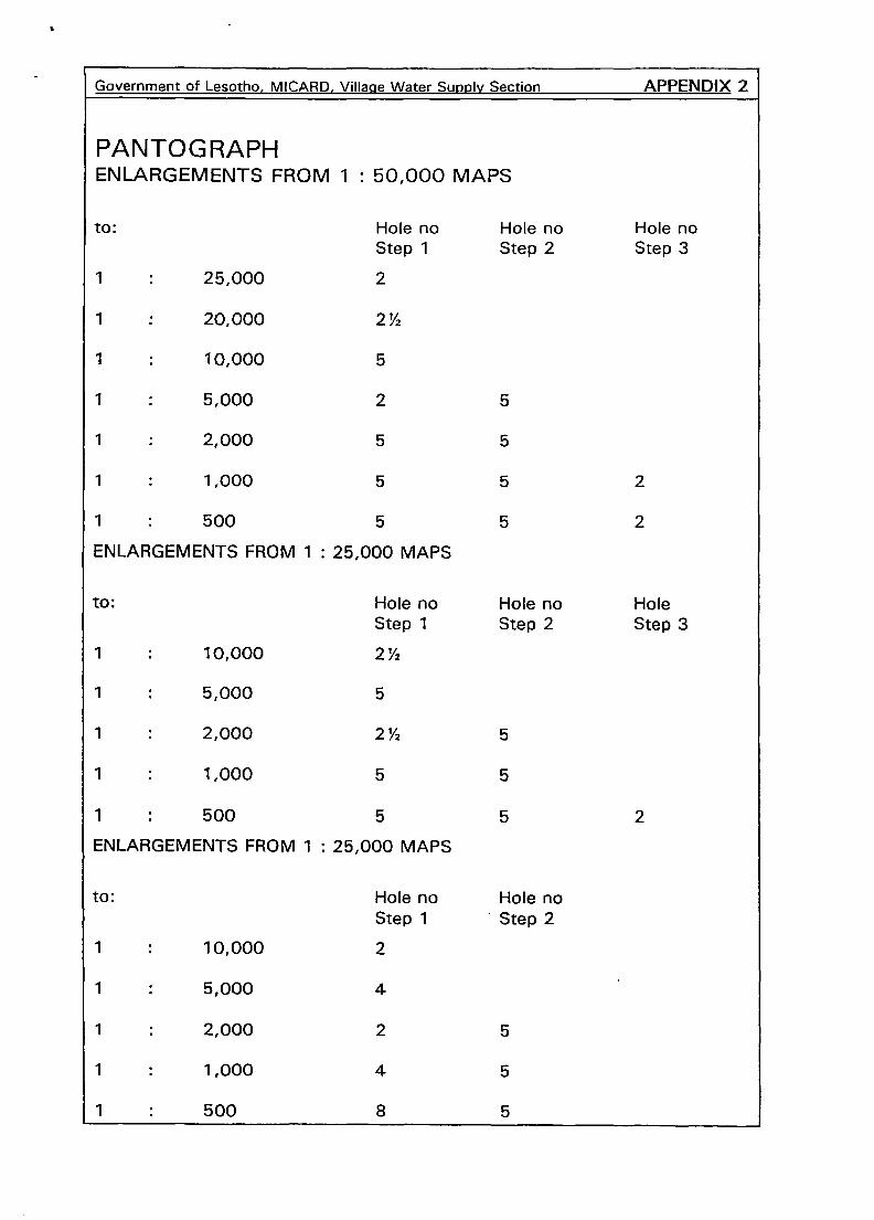
PANTOG RAPHENLARGEMENTS FROM 1 : 50,000 MAPS
to: Hole no Hole no Hole noStep 1 Step 2 Step 3
1 : 25,000 2
1 20,000 2V2
1 : 10,000 5
1 : 5,000 2 5
1 : 2,000 5 5
1 : 1,000 5 5 2
1 : 500 5 5 2
ENLARGEMENTS FROM 1: 25,000 MAPS
to: Hole no Hole no HoleStep 1 Step 2 Step 3
1 : 10,000 2V2
1 : 5,000 5
1 : 2,000 2’/2 5
1 : 1,000 5 5
1 : 500 5 5 2
ENLARGEMENTS FROM 1 : 25,000 MAPS
to: Hole no Hole noStep 1 Step 2
1 : 10,000 2
1 : 5,000 4
1 : 2,000 2 5
1 : 1,000 4 5
1 : 500 8 5
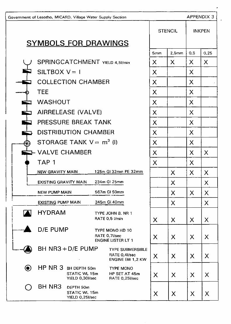
Government of Lesotho, MICARD, Village Water Supply Section APPENDIX 3
SYMBOLS FOR DRAWINGS
EXISTING GRAVITY MAIN 234m GI 25mm
_____- NEW PUMP MAIN -_567m GI5Omm
____- EXISTING PUMP MAIN - 345m GI 40mm
A HYD RAM TYPE JOHN B. NR 1t RATE 0,5 1/mm
DIE PUMP
L.~BH NR3 + DIE PUMP
® HP NR 3 6H DEPTH 50mSTATIC WI 15mYIELD 0,301/sec
O BH NR3 DEPTH 50mSTATIC WL 15mYIELD 0,251/sec
STENCIL INKPEN
‘ SPRINGCATCHMENT YIELD 4,51/mm
SILTBOXV= I
COLLECTION CHAMBER
TEE
WASHOUT
AIRRELEASE (VALVE)
PRESSURE BREAK TANK
DISTRIBUTION CHAMBER
STORAGE TANK V= m3 (I)
- VALVE CHAMBER
TAPiNEW GRAVITY_MA~ 125m GI 32mm PE 32mm
5mm 2,5mm 0,5 0,25
X X X X
X X
X X -
X X
X X
X X
X X
X XX X
X X X
X X
X X XX XX X X
X X
X X X X
X X X X
X X X X
X X X X
TYPE MONO HO 10RATE 0,71/secENGINE LISTER LT 1
TYPE SUBMERSIBLERATE 0,41/secENGINE EM 1,2 KW
TYPE MONOHP SET AT 45mRATE 0,251/sec
X X XX

APPENDIX 4
SIZE OF STENCILS
0 25mm STENCIL
®~3.5mm STENCIL
EE~ 5mm STENCIL
~7mm STENCIL~=1OmmSTENCIL
EBTECHNICAL OFFICE MASERU ®ACTION DATE Ç~jBY ®
SURVEY ‘12.05.80 Q AH Q
®MAT SI EN G 27° 35’ EAST 29°37’SOUTH5KM EAST 0F MORIJA
~I1E PLAN ~1:5’OQO
ç~®~
DESIGN 25.10.80 C Schi QDRAWN 02.01.8 3 C GTR CCHEKED 22.02.83 C Schi QASBUILT 07.07.83 0 UG C
~G0VERNMENT 0F LESOTHO~M1NISTRY0F INTERIOR CHIEFTAINSHIP AFFAIRS ANORURAL
QVILLAGE WATER SUPPLY SECTION OEVELOR
r~is 3 3
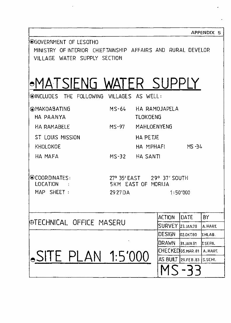
APPENDIX 5
®GOVERNMENT OF LESOTHOMINISTRY OF INTERIOR CHIEFTAINSHIP AFFAIRS AND RURAL DEVELOPVILLAGE WATER SUPPLY SECTION
~MATS1ENGWATER SUPPLY®INCLUIJES THE FOLLOWING
®MAKOABATINGHA PAANYA
HA RAMABELE
ST LOUIS MISSION
KHOLOKOE
HA MAFA
®COORDINATES:LOCATIONMAP SHEET
VILLAGES AS WELL:
MS-64 HA RAMOJAPELA
TLOKOENG
MS-97
MS -32
MAHLOENYENG
HA PEIJE
HA MPHAFI
HA SANTI
27°35’ EAST 29° 37’ SOUTH5KM EAST OF MORIJA29 27 DA
MS -34
1 :50’OOO
~BTECHNICALOFFICE MASERUACTION DATE BY
SURVEY 21JAN.78 A.HART.
‘
~SITEPLAN 1:5’OOO
DESIGN 02.OKT.80 :HLAB.
DRAWN 31.JAN.81 ISEPA.
CHECKE[ 05.MAR.81 A.HART.
AS BUILT 29.FEB.83 S.SCHI.
MS-33
-D-oCD
Q-)<o)
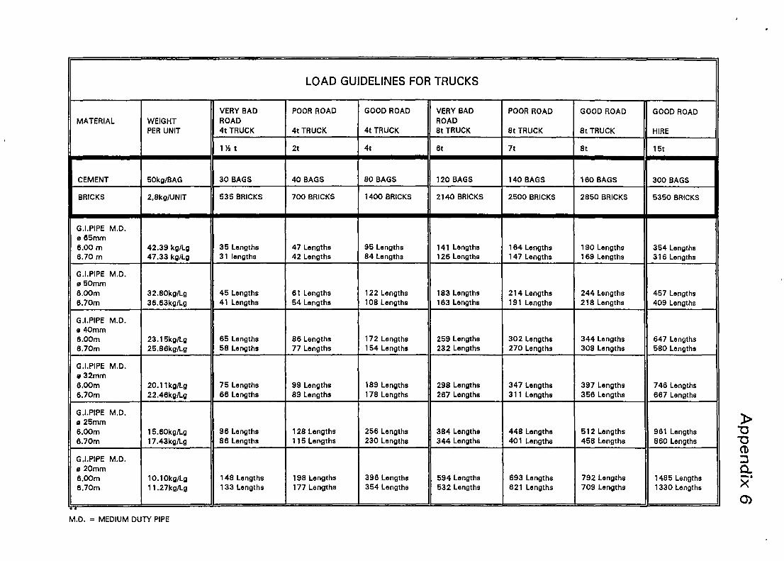
LOAD GUIDELINES FOR TRUCKS
MATERIAL WEIGHTPER UNIT
VERY BADROAD4t TRUCK
POOR ROAD
4t TRUCK
GOOD ROAD
4t TRUCK
VERY BADROAD8t TRUCK
POOR ROAD
8t TRUCK
GOOD ROAD
8t TRUCK
GOOD ROAD
HIRE
1)4 t 2t 4t 6t 7t 8t 15t
CEMENT 50kg/BAG 30 BAGS 40 BAGS 80 BAGS 120 BAGS 140 BAGS 160 BAGS 300 BAGS
BRICKS 2,8kg/UNIT 535 BRICKS 700 BRICKS 1400 BRICKS 2140 BRICKS 2500 BRICKS 2850 BRICKS 5350 BRICKS
G.I.PIPE M.D.e 65mm6.00 m6.70 m
42.39 kg/Lg47.33 kg/Lg
35 Lengths31 lengths
47 Lengths42 Lengths
95 Lengths84 Lengths
141 Lengths126 Lengths
164 Lengths147 Lengths
190 Lengths169 Lengths
354 Lengths316 Lengths
G.I.PIPE M.D.s 50mm6.00m6.70m
32.8OkgILg38.63kg/Lg
45 Lengths41 Lengths
61 Lengths54 Lengths
122 Lengths108 Lengths
183 Lengths163 Lengths
214 Lengths191 Lengths
244 Lengths218 Lengths
457 Lengths409 Lengths
G.I.PIPE M.D.e 40mm6.00m6.70m
23.l5kg/Ig25.86kg/Lg
65 Lengths58 Lengths
86 Lengths77 Lengths
172 Lengths154 Lengths
259 Lengths232 Lengths
302 Lengths270 Lengths
344 Lengths309 Lengths
647 Lengths580 Lengths
G.l.PIPE M.D.e 32mm6.0Cm6.7Om
20.1 lkg/Lg22.46kg/Lg
75 Lengths66 Lengths
99 Lengths89 Lengths
189 Lengths178 Lengths
298 Lengths267 Lengths
347 Lengths311 Lengths
397 Lengths356 Lengths
746 Lengths667 Lengths
G.I.PIPE M.D.e 25mm6.0Cm6.70m
15.8Okg/Lg17.43kg/Lg
96 Lengths86 Lengths
128 Lengths115 Lengths
256 Lengths230 Lengths
384 Lengths344 Lengths
448 Lengths401 Lengths
512 Lengths458 Lengths
961 Lengths860 Lengths
G.I.PIPE M.D.e 20mm6.0Cm6.7Om
1O.lOkgILg11.27kgILg
148 Lengths133 Lengths
198 Lengths177 Lengths
396 Lengths354 Lengths
594 Lengths532 Lengths
693 Lengths621 Lengths
792 Lengths709 Lengths
1485 Lengths1330 Lengths
M.D. = MEDIUM DUTY PIPE
V
(/ )<
---‘S.
/
IT 05
A 2492
NiberHaf~
..‘Matebeleng- ‘k.. - -
\
/
-L -~
“Maqdkoen~~BI 05
A 2438Molekane
\-
—S --S ‘f
/
-
NtelIe
‘Makalane•N.\ S
j -\-I
‘-/_ J-,
><
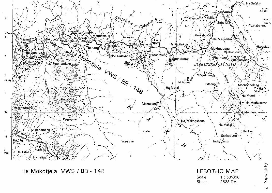
Ha Mokotjela VWS / BB - 148
N\ -S
I fi
LESOTHO MAPScaleSheet
1: 50’OOO2828 DA
‘--J
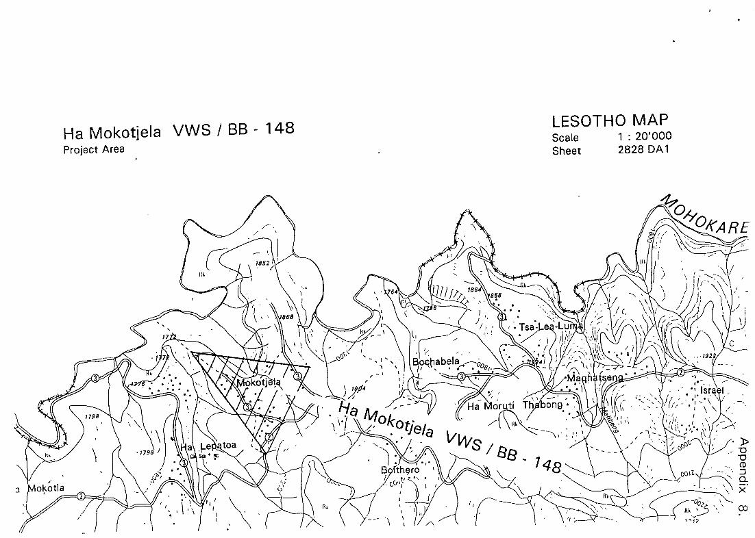
Ha Mokotjela VWS / BB - 148Project Area
LESOTHO MAPScale 1: 2O’OOOSheet 2828 DA1
RE
>0~0CD
o-X
œ
Appendix I I.
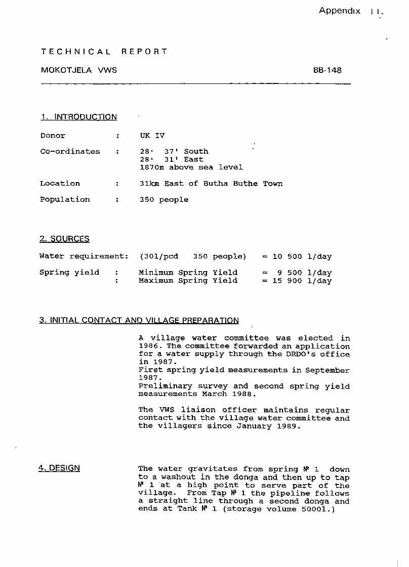
TECHNICAL REPORT
MOKOTJELA VWS
1. INTRODUCTION
Donor UK IV
BB-148
Co—ordinates
Location
Population
2. SOURCES
280 37’ South -
28° 31’ East1870m above sea level
31km East of Butha Buthe Town
350 people
Water requirement: (301/pcd 350 people) = 10 500 1/day
Spring yield Minimum Spring YieldMaximum Spring Yield
= 9 500 1/day= 15 900 1/day
3. INITIAL CONTACT AND VILLAGE PREPARATION -
A village water committee was elected in1986. The committee forwarded an applicationfor a water supply through the DRDO’s officein 1987.First spring yield measurements in September1987.Preliminary survey and second spring yieldmeasurements March 1988.
The VWS liaison off icer maintains regularcontact with the village water committee andthe villagers since January 1989.
4. DESIGN The water gravitates from spring N2 1 downto a washout in the donga and then up to tapN2 1 ‘at a high point to serve part of thevillage. From Tap N2 1 the pipeline followsa straight line through a second donga andends at Tank N9 1 (storage volume 50001.)
Appendix 11.
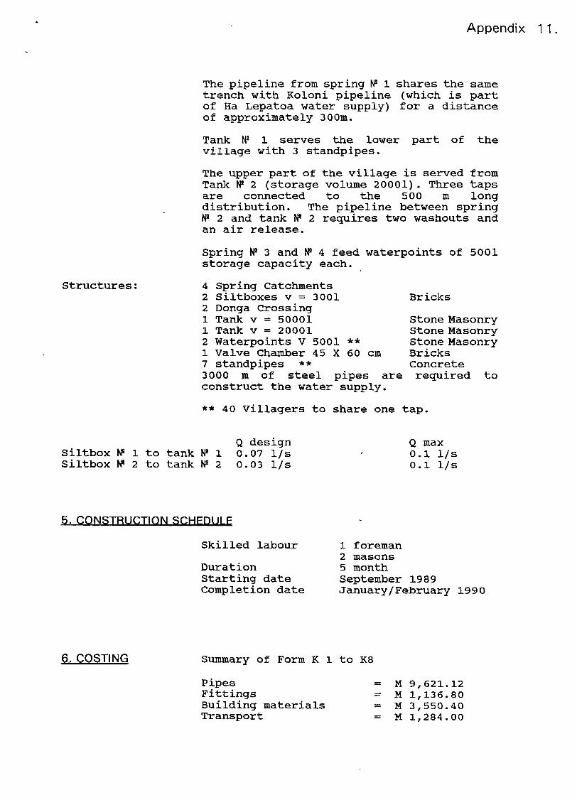
The pipeline from spring M 1 shares the sametrench with Koloni pipeline (which is partof Ha Lepatoa water supply) for a distanceof approximately 300m.
Tank N2 1 serves the lower part of thevillage with 3 standpipes.
The upper part of the village is served fromTank M 2 (storage volume 20001). Three tapsare connected to the 500 ni longdistribution. The pipeline between springM 2 and tank M 2 requires two washouts andan air release.
Spring N2 3 and M 4 feed waterpoints of 5001storage capacity each.
4 Spring Catchments2 Siltboxes y = 30012 Donga Crossing1 Tank y = 500011 Tank y = 200012 Waterpoints V 5001 **1 Valve Chamber 45 X 60 cm7 standpipes **
3000 in of steel pipes areconstruct the water supply.
Stone MasonryStone MasonryStone MasonryBricksConcrete
required to
** 40 Villagers to share one tap.
Siltbox M 1 to tank N2 1Siltbox M 2 to tank M 2
Q design0.07 1/s0.03 1/s
Q max0.1 1/s0.1 1/s
5. CONSTRUCTION SCHEDULE
Skilled labour
DurationStarting dateCompletion date
PipesFittingsBuilding materialsTransport
1 foreman2 masons5 monthSeptember 1989January! February 1990
= M 9,621.12= M 1,136.80= M 3,550.40= M 1,284.00
Structures:Bricks
6. COSTING Summary of Form K 1 to K8

Appendix •11.
WagesContingencies
= M 6,500.00= M 2,207.68
Total M24,3 00.00
M1O,000. 00
M 69.43
Although only 22 litres of water can besupplied during dry periods this will be agreat improvement over the presentsituation.
Expected contribution of village labour
Cost per capita excluding village labour
7. FINAL COMMENT
Date: District Engineer:
Government of Lesotho, MICARD, Village Water Supply Section - FORM A
INITIAL VILLAGE INFORMATION
DISTRICT:a,
VILLAGE: ______________________ Ref. No:___________
Villages included: a)______________________ b) _______________ C) _________________d)________________________ e) ________________ f) __________________
Where is the village located: S
Coordinates: ________________________ East ______________________ South --
-
1) INFORMATION ABOUT POPULATION
Village Yes D No D Residents ____________________Primary School Yes D No D Pupils ____________________Secondary School Yes D No D Pupils ____________________High School Yes D No D Students ___________________Boarding School Yes D No D Students ___________________Clinic Yes D No D Beds/Staff ____________________Mission Yes D No D Sisters + staff _____________________Police station Yes D No Q Permanent staff____________________Cour-t Yes D No D Permanent staff___________________
Total Population = = = = = = = = =
2) INFORMATION ABOUT SOURCE
Source presently used: D Spring (No) D Borehole (No) D Dam, River
Location of source: D Above village D Below village D In villageDistance to source: D 0-100 m D 100-1000m D More than 1km
Is the source polluted: D Yes D NoIs the source subject to drought: D Yes D NoAre there other SPRINGS which could be used: D Yes D NoDistance to these springs: D 0-100 D 100-1000m D More than 1km
3) GENERAL INFORMATION
Accessibility by road: D Good D Bad D Not accessibleCommittees existing: D VWC D VDC D NoneApplication to DRDO: D Yes D No Year ____________________Funds collected: D Yes D No Amount ____________________
Existing supply: D Yes D NoType: D Gravity El Pump D Handpump
Remarks: S
Compiled By: ________________________________ Designation: _________________________
Place: _________________ Date: ____________ Signature: ___________________________
Government of Lesotho, MICARD, Village Water Supply Section FORM B
PRELIMINARY SURVEY
Location: 0 ‘E ° ‘S
Extract: Map no Scale
Project: Ref. no:
Villages:
Institutions: -
Population: Village Contribution: M —-~4
Chief: Application:
DVDCChairman:
DVWC
Date:Survey
By:
(1)
(2)
(3)
(4)
(5)
(6)
(7)
(8)
(9)
(10)
:11)
12)
13)
Key to attached copy of map
14)
Government of Lesotho , MICARD, Village Water Supply Section
SPRING YIELDS
FORM C
PROJECT
REF.NO—S
SOURCE D SPRING D BOREHOLE
D HANDPUMP~ DIE PUMPD
D GRAVITYD HYDRAMD SOLAR
DATE SOURCE NO.
1 2 3 4 TOTAL
s/I lis s/I I/s s/I I/s s/I I/s
P.Mnyisldurn,,
-
~-
-.
Max, y$sldlin-In
S
- ‘
- - -
S
p.,dsym’ -~. -
SS~~,
M.xyi.ldpi.rdsym
1-~ ‘
~
‘-
S
-- -:~
Ccl? o,m
.0_v,1,
- -
.5
S
-
POPULATION TO BE SERVED : people
WATER REQUIRED: m3/day
WATER AVAILABLE: m3/day
I/cd

Government of Lesotho, MICARD, Village Water Supply Section FORM E
LOCAT~0N : REF. NO: -
DATE : SURVEYOR: D TICK RIGHT
FROM TO ANGLESDISTANCE HORIZONTAL
DISTANCEI red
VERTICALDISTANCE
~
RED.. LEVEL
Horizonal
D90°
D 10O~
Vertical
EJ9O°
D 10O~
PT LEVEL
-~
S

Government of Lesotho, MICARD, Village Water Supply Section FORM F
WATERFLOW FRICTION IN MM/M
No ofTaps
FlowI/s
20 mm 25 mm 32 mm 40 mm ~0 mm
1 0.20 26.6 10.2
2 0.40 96.5 36.4 7.6 -~
3 0.50 55.3 11.5 5.4 -
4 0.60 16.0 -7.8
5 0.70 21.3 10.2 3.5
6 0.80 27.3 13.4 4.5
7 0.90 34.0 16.5 5.5
8 1.00 41.5 19.3 6.7
9 1.10 23.2 8.0
10 1.20 27.1 9.411 1.25 29.4 10.2
12 1.30 31.7 10.9
13 1.35 34.0 11.7
14 1.40 36.3 12.5
15 1.45 13.4
16 1.50 14.3
17 1.55 15.1
18 1.60 16.0
19 - 1.65 17.0
20 1.70 18.0

Government of Lesotho, MICARD, VUIage Water SuppLy Secton
~
S- ~~OBMG~
S S ~~
4
S-
S I
1~S-
&
YE
‘sTS -~—-—~ ‘S
— I
• -~- ~I’’ ~~E’ ,
-S -‘ ~ S
4-
~ ::L~ ±— r—r------------j--’--\ H— -~-----‘-——----- -----4--’---
L ‘ : - • S
I •
‘S ~-i~~-”~ -r — ‘\~_\~ S
-~ L1~-
j1IZI~Jt±It~:it ~ïI)TTJt~I ~ -
-:E TT~siH”:~ ~:L~1LL\~LLLS T ~\ ~
L S S ~ S\ S
H
TI~iIi~H~tHI�~H~’IJIN±11
-- H --i-H-fl— -- }~SH~\ ~--:----~ ~ii:~ 1_t.j__!i~~~
~
~‘I T-~-RTR-- ~— ~
o
~, Œ~ ‘q -~ c-~~ ~- ~
~ C—l r’~ ~ .5—J —
o-
f-
Government of Lesotho, MICARD, Village Water Supply Section - ~~FORM G
____ -__I~
:‘Y\ITTJ
E-~
-.2- -- -4’
-3.
r —
-S-
r r\ IS
\---S---~-—~ -~-~--~----±-\+I • -
____________ S• S S I
I s S
, S S • I — —
- 1——— —~ —~
- ‘ ~-ç~i‘ j -~ I;,~
-‘ ~—\--‘- r-T---±--\-~~-
- - ~--1-~-.-~--— ~4- ~L-~\ -
-- --- ~\, -l \ • I -
L~LS.L . -
± - ~ --k-~-;“.: J ;\Ii I i:’F~I\!_ • S
I t ~r ~r-rr -‘ \1 —I’-~---~ — —~--
S \~1~
S ~ - T • -~ • r - - - S S ~L_L~_
-___
~-~r j -~ ~- --~ jS J - S
~ ~\~:-
~‘o, U’~
c Q C--Lo C) Q
Qr-’ ~o ui -‘It ~i ~- “- ‘S ~
•_5’ ‘5-- ‘5- ‘5- .5- ~ —~ Q Q Q
Government of Lesotho, MICAFID, Village Water Supply Section
HYDRAULIC CALCULATION
DESIGN
SCALE VERTICAL 1 : 00
SCALE HORIZONTAL 1 : ‘0001) POINT NUMBER
2) DISTANCE BETWEEN POINTS
3) REDUCED LEVEL
4) STATIC PRESSURE HEAD
5) FLOW RATE
6) PIPE SIZE AND TYPE
7) FRICTION LOSS rn/km. mm/rn
8) FRICTION HEAD m
9) - FRICTION CHAINAGE m
10)
TECHNICAL OFFICEACTION DATE
SURVEY
-- ~~FORM H
______ BY
CHECKED ~.
GOVERNMENT OF LESOTHOMINISTRY OF INTERIOR CHIEFTAINSHIP AFFAIRSAND RURAL DEVELOPMENT
VILLAGE WATER SUPPLY SECTION
~.
~
--~
VILLAGE (No/Name)
COORDINATES :LOCATION :
PIPELINE: FROM TO
DYNAMIC PRESSURE HEAD m
Government of Lesotho, MICARD, Village Water Supply Section FORM Il
MATERIAL REQUIREMENTS
NAME OF VILLAGE: REF. NO.
1. PIPES1.1 GI-PIPES
SECTION 80mm 65mm 50mm 40mm 32mm 25mm - 20mm
St
TOTAL
1.2 PE-PIPES S
SECTION 80mm 65mm 50mm 40mm 32mm 25mm 20mm
TOTAL
Government of Lesotho, MICARD, Village Water Supply Section FORM 12
2. FITTINGS2.1 BRASS - FITTINGS
ITEM 80mm 65mm 50mm 40mm 32mm 25mm 20mm
Bibcock
Gatevalve
Globevalve
Non return V.
Air release V. 5 -
Float valve - - -
2.2 GI - FITTINGSITEM 80mm 65mm 50mm 40mm 32mm 25mm 20mm
Socket S
Nipple
Union flat face
Union conic
Red. socket
Elbow F/F 90°
Elbow M/F 90°
Bend M/F 45°
Red. bush
Tee equal F/F 90°
Plug solid
—~o—I
NO OF STRUCTURES
CEMENT BAGS
BRICKS PCS
SHAPED STONES M3
CRUSHED STONES M3
SAND M3
MESH REF 100 M2
RODS 6MM Ml
RODS ø 8MM Ml
C,I.MH COVER PCS
GABION (wovEN) 2X1X1m
GABION (wovEN) 2X1 X0,5m
BARBED WIRE
POLES
I t
—— I
STANDARD PLAN NO
STRUCTURE
C
z
Hm
f-
C~)oCD-t
3CD
I-,o
CD
on
o
û
D
10CD
CD-t
(J)
C
(I)(bono
j
Government of Lesotho, MICARD, Village Water Supply Section FORM 1<1
BILL 0F QUANTITIES AND COSTING/ACTUAL COST
VILLAGE: REF.NO: DATE:
1. PIPES1.1 GI-PIPES -________________________
ESTIMATE ACTUAL
SIZE QUANTITYUNIT
UNITCOST
ESTIMATEDCOST
DELIVEREDTO SITE
RETURNEDTO STORE USED
UNITCOST
ACtUALCOST
80mm .
65mm
50 mm
40mm
32 mm
25 mm
20mm
TOTALGALVANIZED STEEL PIPES
1 .2 PE - PIPES
ESTIMATE ACTUALSIZE QUANTITY
UNITUNITCOST
ESTIMATEDCOST
DELIVEREDTO SITE
RETURNEDTO STORE USED
UNITCOST
ACTUALCOST
80mm
65 mm
50mm
40mm
32mm
25 mm
20 mm
TOTAL POLYETHYLENEPIPES
TOTAL PIPES
Government of Lesotho, MICARD, Village Water Supply Section FORM K2
BILL OF QUANTITIES AND COSTING REF. NO:
2. FITTINGS2.1 BRASS FITTINGS -S
ACTUALITEM SIZE QUANTITY
UNITUNITCOST
ESTIMATEDCOST
DELIVEREDTO SITE
RETURNEDTO STORE USED
UNITCOST
ACTUALCOST
L)90~t_~
20mm
>
~
80mm
—
.
65mm
50mm
40mm
32mm
25mm
20mm
80mm
65mm
50mm
40mm
32mm25mm
20mm
>
~~~~zoZ
80mm
65mm
50mm
40mm32mm
25mm
20mm
<~
~w<o:
40mm
25mm.
~
I-w<>o~if>
40mm
25mm 5
20mm
ITOTAL BRASS FITTINGS T
Government of Lesotflo, MICARD, Village Water Supply Section FORM K3
BILL OF QUANTITIES AND COSTING REF. NO:
2. FITTINGS2.1 GI FITTINGS -
ACTUALITEM SIZE QUANTITY
UNITUNITCOST
ESTIMATEDCOST
DEUVEREDTO SITE
RETURNEDTO STORE USED
UNITCOST
ACTUALCOST
80mm
65mm ~:
50mm
40mm32mm -______ ~S
25mm
20mm
w-J
~z
80mm
65mm
50mm
40mm
32mm-
25mm
20mm
I-
80mm
65mm
50mm
zo
40mm
32mm25mm20mm
uz0L)~
~
80mm
65mm
50mm
40mm
32mm25mm
20mmS
I-w~(JoC1~)
(9Zo —
Dowo:
Government of Lesotho, MICARD, Village Water Supply Section FORM K4 jBILL OF QUANTITIES AND COSTING REF. NO:
ACTUALITEM SIZE QUANTITY
UNITUNITCOST
ESTIMATEDCOST
DEUVEREDTO SITE
RETURNE USEDDTO STORE
UNITCOST
ACTUALCOST
80mm
65mm50mm
:: -
25mm
20mm -
o~IL~
~
~w
80mm
65mm
50mm
40mm
32mm
25mm
20mm
~,~.
~
~z~
80mm
65mm
50mm
40mm
32mm
25mm20mm
(I)
~
~~
~a:
80/65
80/50
6~40
50/40
50/32
50/25
50/20
40/32
40/25
40/20
32/2532/20
25/20
Government of Lesotho, MICARD, Village Water Supply Section FORMK5
BILL OF QUANTITIES AND COSTING REF. NO:
ESTIMATE ACTUAL_____ -_____
ITEM SIZE QUANTITYUNIT
UNITCOST
ESTIMATEDCOST
DEUVEREDTO SITE
RETURNEDTO STORE
USED UNITCOST
ACTUALCOST
°~o,IL
IL
-J<~
wwI-
80mm
65mm
50mm
40mm . -
S -
32mm
25mm
20mm-~
80mm
65mm
50mm
40mm
32mm
25mm
20mm
TOTAL GALVANIZED FITTINGS
TOTAL FITTINGS I L

Government of Lesotho, MICARD, Village Water Supply Section FORM K6
BILL OF QUANTITiES AND COSTING REF: NO:
3. BUILDING MATERIALESTIMATE ACTUAL --
ITEM/SIZE QUANTUNIT
UNITCOST
ESTIM.COST
DELIV.TO SITE
RETURNTO STORE
USED UNITCOST
ACTUALCOST
Cement
Bncks
Crushed stones
Localsand -- — —
MeshRef.100
Rod 08 mm
RodO 10 mm
Man hole cover c.i.
Ladder ALU/I RON
Chawl DoŒ
Drain mesh 8.8 cm
Wire e 2 mm
Nails (50(75/100mm)
Gabion 2x1x1 m ~_______
Gabion 2xlxO,5m
Nais f. roof ÷washers
Dicing oil
Thread sealing tape
Slab formwork 200x100 cm
SAP 9~2N (23x5cm)
SAP 6.l~(15x2,5cm)
SAP 2,5”.1 5~(6,5x3,5cm)
Petrol f. Jackh. + vibrator
Two Stroke oil f. .Jackharnmer
Chise’ f. Jackhammer
Water Minder Tools Box
Soil protection egtrees/bushes
Roofing sheets Size:
Barbed Wire
Wooden Creosoled Poles
Dropper
Standards
S
Government of Lesotho, MICARD, Village Water Supply Section FORM K7
BILL OF QUANTITIES AND COSTING REF. NO:
4. TRANSPORT
ESTIMATE ACTUAL
TONS RATE!TRIP
NO!TRIP
ESTIM.COST
TONS RATE!TRIP
NO!TRIP
ACTUALCOST
TRANSPORTTO SITE
LOCALTRANSPORT
TOTAL TRANSPORT- �~-
5. SKILLED LABOURESTIMATE ACTUAL
MANDAYS
DAILYRATE -
ESTIMATEDCOST
MANDAYS
DAILYRATE
ACTUALCOST
FOREMAN
MASONS
TOTAL SKILLED LABOUR
6. VILLAGE LABOURESTIMATE ACTUAL
MANDAYS
DAILYRATE
ESTIMATEDCOST
MANDAYS
DAILYRATE
ACTUALCOST
VILLAGE LABOUR
TOTAL VILLAGE LABOUR
10% OF POPULATION X CONSTRUCTION PERIOD
t~overnmentof Lesotho, MICARO, Village Water Supply Section FORM K8
BILL OF QUANTITIES AND COSTING REF. NO:
COMPILATIONESTIMATEINCL.VILLAGELABOUR
ESTIMATEEXCL.VILLAGELABOUR
ACTUALINCL.VILLAGELABOUR
ACTUAI~EXCL.VILLAGE’~LABOUR
1. Pipes
2. Fittings ~- - -
3. Building material -
4. Transport
5. Skilled labour
6. Village labourS
Cost:
Contingencies (10 - 1 5%)
Total Cost:
Cost per capita (Population = .... .
Name:
Designation:
Signature: DateS
Government of Lesotho, MICARD, Village Water Supply Section FORM K9
BILL OF QUANTITIES AND COSTING FOR HANDPUMPS
Project : Ref. No.
Population : Donor
No. of Handpumps : Type
ESTIMATE ACTUAL -
ITEM QUANTITYUNIT
UNITCOST
ESTIMATEDCOST
QUANTITYUNIT
UNITCOST
ACTUALGQST
DRILLING
HANDPUMPS
PLATFORMCONSTRUCTiON
TOTAL COST .
COST PER CAPITA
COMMENTS:
Compiled by: Name :
Designation :
Date :
Signature :
Government of Lesotho, MICARD, Village Water Supply Section FORM Li
BREAK-DOWN REPORT FORM VILLAGE WATER SUPPLY
REF. NO:
CHIEF:
CHAIR PERSONVWC:
DATE:
with a cross the corresponding break-down
POMPO (TAPI
I TN~e~i:o~gihinkE No water is coming to the siltbox POMPO( TAP)
D No water is coming to the tapE Handpump is not working
Any other remarks~
This form will be sent to: Village Water SupplyMaintenance SectionP.O. Box
VILLAGE:
DISTRICT:
WATERMINDER:
Place circle around trouble spot and indicatebelow:
CORP.. IRON TSU4K
POMPO (TAPI
PatlPO EALETSOHO NO

Government of Lesotho, MICARD, Village Water Supply Section FORM L2
TLALEHO EA HO SE SEBETSE HOA PHEPELO EA METSI
NOMORO:
RAMOTSE:
MOLULA-
SETULO:
- - LETSATSI:
Ngola lesakana sebakeng seo khathatso e leng hona tenglesakaneng le amanang le khathatso ka tlase.
o be o bontse ka sekere
P0MPG (TAP)
0E ~
E Ha ho metsi a fihiang sefeng (siltbox) POHPO( TAPID Ha ho metsi a fihlang pompong (tap)E Pompa ea letsoho ha e sebetse
Hialosa tse ling:
Foromo ena e khutlisetsoe Maseru atereseng ena:-
Village Water Supply
Maintenance SectionP.O. Box
MOTSE:
S ETEREKE:
LEBITSO LAMOLISA:
CORR. IROI~ITANK
(HANOPUM2,~POMPOEALETSOHO NO
P0MPG (TAP)
Governmentof Lesotho, MICARD, Village Water SupplySection FORM Ml
MONTHLYCONSTRUCTIONREPORT Page
Gravity MonthlYearDrilling iiHP Installation — RegionlDistrict
1. CONSTRUCtION ACTrVrIThS - -
Project Ref. No. Donor Pop.Progress %Start Date
Compi. DateRemarks
. -
2, TRANSFERS
I [Name Date From To Remarks
3. PROJECTSINITIA TEDTHIS MONTH
Project Ref. No. Donor Pop. Remarks
Prepared by DE:
Date:
Checked by RE:
Date:
Distribution: RE
Government of Lesotho, M1CARD, Village Water Supply Seclion FORM M2
MONTHLY MATh1TENANCE REPORT Page
Gravity J Month/YearBorehole — J
HP L_ Region/District
.1. MAINTENANCE ACTIVITI
ProjectRef. No. HIP No.
Progress %Start Date
Compi. Date
Remarks(RehabilitationlExiusions etc)!-~ . -
2. PROJECFS~INTfl &TPT) T1IP
Ref. No.
MONTH
‘ RemarksProject HP No.
Prepared by DE:
Date:
Checked by RE:
Date:
Distribution: RE
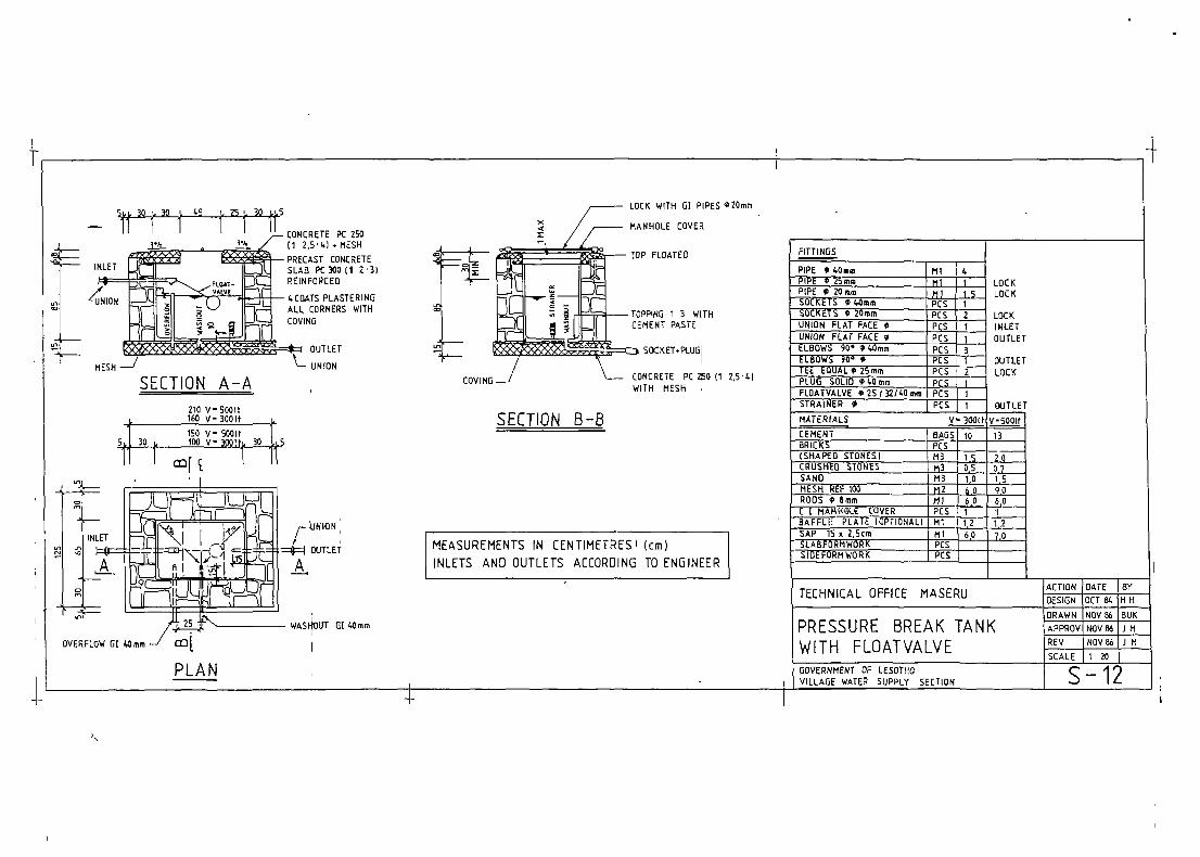
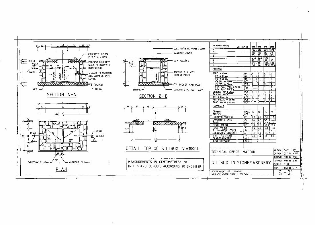
DETAIL TOP OF SILIBOX V=i000[t
MEASUREMENTS IN CENTIMETRES’ (cm)INLETS AND OUTLETS ACCORDING TO ENGINEER
M EASUREli ENISVol UliE It
SECTION A-A
7541 10041
A L
5i. 22-St. B 22.51.5
SOCKET—PLUG
PC 2~(1.25,1.)
SECTION B—B
27 Ç AS 45 1411 77 Ç,
BAFFLE PLATE
A j~72~255B_______________________________ 106 152 163 210
Th~ri-t______ 7
35 35 -~ 52,5~7T5~
FITTINGS
PIPE 040mm t.~1Ï
PC SSOCKETS 0 20mm PCSUNION FLAt FACE 0 40mm P13 1
T
PCS 2
UNION FLAT FACE 0ELBOWS 900 040mmELBOWS 90°0TEE EQUAL 0 1TEE EQUAL 0 25mm 1I~~I~~1PLUG SOLID m4Omm PCS
1
21 tI1~2
I
MATERIALS
8 13 15 17CEMENTBRICKS PCS 350 1.70 600 700(SHAPED STONES) M3CRUSHED STONES
-
SAP 15 x 2.5cm
~Y ~Ç 0,7 I o,~ TT
;~J~~_~—i1-Ji-
Ml 1~2I 12 ~~1j_ 6.0 I 7.0 LLQ. J~i
SLABFCRMWORK ISIOEFORHWORK PCS
3.’.
PLA N
TCTION DATE BYTECHNICAL OFFICE MASERU DESIGN SEPTB3JII PF
DRAWN NOV 86JBUKAPPROV NOV B6~JM
SILIBOX IN BRICKWORK 120
REV NOV 06[J li
GOVERNMENT OF LESOTHOVILLAGE WATER SUPPLY SECTIGN B—01

7,: 1
BUtLDU4Q HArERIAL REF NO F PM F3flU ~ — — i;~ gus~ ItEM ROCS CIMH X~fl~S~itT ~ ~Otl ~3i jct~ t~i Ei~s~ti~tr Tir pr ~t6ii~ SRAIM S~PLAN STR~XTUPE STRUt- CEMENT ~CXS StM(Z STD4�S SANG REP e lin CŒIRR P•P c~F F-F ~cr ~œ 9o ~ 90’ EŒJAL EQUAL SaiD fAIRE R VA1.VR
IC ¶~ b.gt FCS & S3 i3 i~ i PCI ~4na ZR... kRma 20n SEem I ~o 2O.~ 50 ‘ 2F ~ ‘ ‘~‘ ~
SPRIESAICFF~NT ~LjL~SILThQX3RøLT ~ ~~t4 EH EEEE ~ ~~~F1E
.~:—- -SRRLT 13 ~7OI ~ T~- 7SOLT 15 RRO TiT
0i~ i.s~ • ~- ‘ ~ J r r— ~ ~——- —--—-— -
S-I1SILTROX-ISRLT I T1R31 o,aI z :rT;7TTT T~:TT2 ~i rT: .
fl~~LiPRRR�~tx n!::~:rc~i:’~r ~ I— UISTRI&JTIRN s ~ os~ o.3~ o.] ~ — - I 6 ~~-1
S-12 RRK.FLtV3OR 10 J IS~ ES’ i~J ~ ~~ - fl—’-— -
R-1ISILTRO%_15øu___�_z6~ R.3Q6j2j~6~:.:
-COLL/FRRREA ~ L“ UISTR1RIJTION t’ 160 U 04 2 ~j 6 I
R-12F1-RV 3ROLTR3S&OSO~J5S1I6
SORIT:3450.71ja4!11
211 J• - 1~ 2-
-PR-RV
~:Tz-_VCHAEt
zc~:~!i_ •‘
S-ZØTANK-
4516E ~ iT~~~ ~
601R5 zim~ ~6-2.S
67fl d)fl T ~ T r- -~ — fl—j-- ~ ~-—~—--—~~------———--
ffnoJL_2Ai_LJ1~1__l___~1~’~Oi~~l2i8-2
- r ~ ~ - -j- —
- -
S-
-
— -- 2& 211 -. 30’ 15 30j ~JZSI I 10. I—:-- -~ 3m~ 251 --4~L~3~15 ~i1~r -
:iiii ~& ~ - ~
.— Sn
3 35• •• S~ ~2.SI t.5 ZR~ 3Z1 12, :— ~— 7.sII13 461 7.5 ~ 601 381 h6~ 1~ :~ I ~ ~ ~ j ~ ~ I I ~ ~ ~ I
iii- ~~ I
— “— 1Om~ 55 -— 8Sj I~,0: .O~ 621 ‘I 17 I i I I I I— —— ~ 67 tRI I~.°!
S-23 —2Orn~ ikoI - -2~øI lis•! ~
3Q~~j lEI -I-~~,o~O.Oj
0-00 ~— ~ iol 6S0~ - -lu
tSj oilo iool izo
ZSOi 12O~
toi iol
ie~
“LIloi
‘I 19
i~ z&1DO~F J2l.
II R~
~!
-!
I~
i~
I2~ -
-~
-~
Iz
r-
-~ -
~-I -
13 -
s -
-
O
-
j-
I
1
•
-
.
-
I3j -I~
-
— —— Zn
3 00 • -Its 251 16 20 1 10 ; ; I I— ~ 03— —_~~3
&0~
.1_u.s-r—1201
2,013P 1
10 22 1
lac 1
10lii
I.
IL i !
I~
‘
Ir~
.. ——sl1I~ ‘0~ 24~ -L130: ~or 1 12 r : I I ‘ r • I— — —lSm~ ~°I -i~{ii[RP, .5 1 14 I • I I I I , i i r I I I— — —t0m-~ 60 I rI’~ S5r 70i I 17 I j p ! I- —15m3 70 --[s~~~o651 90~ I 1R I • ! r I I I~ ,R-20 • -20m~ 30 00 -~-]‘.0
— . —30r, ieol -:-I”S-30 wP -300LT 04i ~ IG~
i~0 0 l2or•o 120j lit;
15 ~ ~
100CR 26
100~ 2’.
i: 6~
- . -~
. , Io i -i
I
~-
I-~
~s~ i
-~ 3 -II •
-I - o
-I
-
-
i - -
-I 3I -~
p I-r
— — -000LT -I- 20 lia ~o ~I i~ r . I I j I— — —750L1 IRI -I-— — —I000Lf OR;— --
- ~ -ooœtr 25 -
o~ Ito~
api
~-~Iioi
1S~
12’ 1
10~
7
i~ 7
I~ I I
II
II
.
! Iiol I~-~ l9i 0~. lj 10 I I I I I
- -3000LT 29 Z~ ~ IcI 041ij ~°I I , I I j I I
0-30 •— 300L1 12 ‘5o_ •C-~0J~ 10 7 ~l ~ 6 Z il - - 5 I - - 2 - ‘I -~ - I
ROI ~— 500LT 15 OS~ I-i-Io~ tO R Si li -I I ~ ~- i z i 2 - II -I -I— —— bOLT ii S0~ I-:-IRR— -1SCOLT li ~zI I- t’°— —2000L1 2’ 9~j I 1t5. — —300011 20 0 I- -(Is
S-SI WP-500U 16 -jon! ILO
13
~I I6~
~o Ia~
1; ‘
I! 8
r .
1 II
tII
I~I— I
II I
II I
ZSj Il 251
23 11 2~
U ~ ~
1 IS r I I I Iii 10
1 7 2 1 J ~I ~:
21 i 2
I !ii - .
Iil
— — —ISOLT
— — -lSzoLrR
1 -~ l2~S~~I_~!I2.CI tOi 12~ 1 7 ! I
t
I ‘ I20~
- -I~~11.0 ZS~ 19 121 I
•
t- —2RQOLT 251
.bol to~
-I.~ luIr~-j¼0I
w1 ~ 2L
~ “1 26-z5:L___
I I0~
1 ~ 10
- 0;
II
1 - 2 -III
LJ -II
-r ~I- 3 ~ Li 291
8-I-0 ST-PIPERAICPIPP~ F~MCUSE ~SJ~
TOTAL —- I
- .0! i9It~L
t352-S
4—
iol
So_ lOo~00Iz


ft_R~ ~ri~
85
QJI] ~ 750110001f
E-h-ii
r
,~es}ss~L
PRECAST SLABS 1 50
I —
r MANHOLE COVERPRECAST CONCRETE SLAB(1 2 31 REINFORCEO
s
CONCRETE PC 25011 2,5 ‘1° HESH~
TOP FLOATEO
AIRAT4ON 450mm C
4 COATS PLASTERINO -
ALL CORNERS WITHCO VtNO
PC 2SWÏ1 2.5WITH MESH
a ~
Ixl-in °_nt__T
4
SlOE WALLS ACCORDING TOTERRAIN IF NECESSARY
MEASUREMENTS IN CENTIMETRES! (Coi)(J~ETSAND OUTLETS ACCOROINU TO ENGINEER
ACCORDING TOTERRAIN
SECTION A—A
t-
CONCRETE PC 25011 2,541. MESH
HOLDERTHAN
50cm
210
Si] 30 t. 150 t. 30 ~5
- PAVING
SECTION B—B
MEASUREMENTS VOLUME If
o
-I500 750 0)00 20001 3000
A 65 00 50 ~ ThOB ThO ThO ~ 250C 1 ~Ç 105 120 155D 15 15 70 85
FITTINGS I
PIPE øSOmm Ml 1 1 1PIPE
040mm Ml 4 4~ f~PIPE O2Smm LOCK Ml 31’ 111 1PIPE 020mm LOCK Ml 1 1 1BIBCOCKS PCS 1j! 1 1SOCKETS 020mm LOCK )PCS 1~12 ZUNION FLAT FACE 0 INLEIIPCS ii 1 i~ I
1 ‘
1 I11T
z1
ELBOWS 90°OSOmm PCS ~ELBOWS 90°020mm PCS ~
31
LL_F~IJ~2F
211E
ELBOWS 90°O4Omm WO1OFjPCS I 4 CELBOWS 90°0 ‘NLET 1 PCS [fl 1TEE ~DUAL425mm LOCK 1 ~rT2 1PLUG SOLID ø&Omm 1PCS Ii 1
MArERIALS ICEMENT rBAGS 16 18
4 T C1 IT~ Y~1 1
z.1T
1
20 25 29BRICKS PCSSHAPED STONES M3 AL, !~i!L.CRUSHED STONES M3 1,0 1,0 1,0 1,5 1,5SANDMESH R!RODS 0~CCMA?SAP 15
!tiã!o.
SIDEFORMWORK
‘13 2.L, 20 2.5 iL ~13,0 75,0 15,0 19,0 19,0
12,0 12,0 24,0 24,01 1 1 1
LU 7,0 70 -I 10,0 I 10_0iiii1i1i1i1ii ~___
h’LS — I
iii
SO-AK AWAY
PLAN J. 50 J.
TECHNICAL OFFICE MASERU
WATERPOINTV= 500 /75011000/2000/30001t
ACTION GATE TBYDESIGN ~ii~tHPFORAWN DEC 56
zi~iirrrREV 5~~1TM
~_
OOVERNMENO OF LESOTHOVILLAGE WATER SUP~LY SECTION S-31

CONCRETE PC 250
(1 2~5 L) MESHPRECAST CONCRETE—INLET’SLAB PC ~)0(1 2 3-I..RZINFORCED °
1. COATS PLASTERINGALL CORNERS WITHCOVING
PC 250 (T 2,5WITH MESH
MEASUREMENTS IN CENTIMETRES (cm)INLETS AND OUTLETS ACCORDING TO ENGINEER
±
SECTION
CONCRETE PC 250(1’ 2,5 41 MESH
TOPPING 13WITH CEMENT—PASTE
SECTION B—B

¶40
SANG ~)j3 ~MESH REF 100 112 I 100 120—t-- -~ --~—RODS ~ Nmm I Hi I I20 l7t.
DOOR - FRAME StEEL1 P[S 
DRAIN MESH j PCS
SLABFORHWORX - I_______ —~
TECHNICAL OFFICE MASERU
STORAGE TANKVOLUME 20 / 30 M3
‘4
141L 1.5 90 35 L10 I.
Il 2,5 LIVIB RAT EQ
., •I~1 •1 I
I SECTION~—~77 10J~L20I. 40 I~
1 1
MEASUREMENTS IN CENTIMETRES’ )Cm)
INLETS ANO OUTLETS ACCORDING TI) ENGINEER
GOVERNMENT O~ LESOIHOVILLAGE WATER SUFPI.Y SECTION

H- O—J-
UNION
~ ~ INLET
PLAN
~BB~88~
1M3
— A~RATIDN050 mm
WASHOUTO5Ocimi
U~ SUPPLY }îo VALVE CHAMBER
OVERFI.OW
TOP FLOATEO
IIP~LETI
I- A
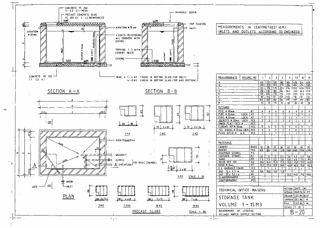
TANK 1—4113 1HESH IN5 —15M3 ZMESH IN
MEASUREMENTS N CENTIMETRES I (cml[~j~ETS AND OUTLETS ACCORDING TO ENGINEER
t
SECTiON B—B
MEASUREMENTS VOLUME M3 1 2 3 4 S 7,5 10 J 15
B
tOol.
‘JH ~ -~
A
~LOCK
2113 3113
L,~65 ~ 2x~ ‘I
A 225 240 245 295 I 300 I 420 540 J~]~QB~
215)~
230~
235T~
265 ~9,~ 220
400~
520 F620~
0 iSO140
220210
200190
250 250190] 230
250230
ZSOJI 260p[~1o
60¶05
150105
130155
130 ~1551 160
170160
~[j~o166 170
15 is is 151 20 20 20 20FITTINGS 1PIPE 0 50mm Ml 6 6 6 6 6 6 6 6PIPE 0 25mm LOCKPIPE 0 20mm LOCK
RTMl
111
ii1
i1
11
= i~ i1 1 1
SOCKETS 0 20mm LOCK PCS 2 2 2 2] 2 2 1 L2UNION FLAT FACE C PCSELBOWS 900050mm PCSTEE EŒUALO25mÇnLOCK PCS
52
52
5 S 52 21 1
52
~L..52 2
PLUG SOLID 0 W O PCS 1 1
~
.
T 1 1
MATERIALS-
I.CEMENT BAGS 16 21 25 26 3S 46 55 67BRICKS PCSSHAPHED STONES 113 2,5 3.0 4,0 LS 5,0 1 7,5 6,5 11,0
IONES MO j~ ,j~ ,j~ 3.5 .~ .j~2~-~ i~2~.i~
MESH REF 100RODS 0 0mm
H2~T
10,0)~
16,0i~
15,0~J
17.0~
26,01 ~5~46,0
40,0 62,0~
C I MANHOLE COVER PCS 1 T ~“T’~(1 1 1 ~[j
SAP 15o2,Scm ~fl j~ ~JSAP 23 o 5,0 Tm Ml .]L~~L~Qi2.~Jt~SLABFORIIWORK PCSSIDEFORMWORK PCS
TECHNICAL OFFICE MASERU DESIGN MARB~
STORAGE TANK ~VOLUME 1 — 15 M3 SCALE oEc:6 iN
.~_~ii SCALE I
LU �1 ~llI~J ~I ~IIfUJ ~i ~ = [Dliii
_________ 4x75 ,J.
60,J. 5x60 4 7x71 I.
5113 10113 15113
PRECAST SLABS SCALE 1100 GOVERNMENT OF LESOIHO — 20VILLAGE WATER SUPPLY SECTION
H-

TOPPING 1 3 WITHCEMENT PASTE
CONCRETE PC 250 Ii 2,541WITH MESH
It
GOVERNMENT OF LESOTHOVILLAGE WATER SUPPLY SECTION
LOC KLOCII
WE KINLETOUTLET
OUTLETLOC K
‘I
020mm
SECTION A—A
FITT1NOS
210 VS001f160 V300IF
150 V— 5001f 130 . 100 V— 3001t. 30 LS
COVING
:1 - 1 11
SoCKET+PLUG~
SECTION B-B
PIPE ~ 40.m [iiiPIPE 0 25mmPIPE 0 20mm
ni~__ui
I_2_
~ ~
PCS
SOCKETS 048mmSOCKETS 0 20mmUNION FLAT FACE OUNION FLAT FACE oELBOWS 90 o LOom ~cs 3EL8OWS 900 • PCSTEE EQUAL 0 25mm ‘~T’~2PLUG SOLID O40 mmFLOATVALVE 02S132/40mm PCS 1STRAINER 0 PCS OUTLET
MEASUREMENTS IN CENTIMETRES I (cm)
INLETS AND OUTLETS ACCORDING TO ENGINEER
WASI~OU1~01 46mm
MATERIALS V-500!fCEMENT Ii~ -~-‘- -ii———BRICKS J .EC~_ISIIAP�D STONESI J l-13
— ]~!ii~~— t!iL
tii_RODS 0 8mm ~
LU LPLATEI
~AP 15 x 2,Scm ~
j~ j~~_
~L~i~_J~L.j~Q_6,0
~
.~L_J~_~6,0~~:___
L~__SLABFORMWORK PCSSIDEFORM WORK PCS
PLA N
TECHNICAL OFFICE MASERU
PRESSURE BREAK TANKWITH FLOATVALVE
ACTIONDESIGNDRAWNAPPqOVREVSCALE
OATEOCT 84NOV66NOV86NOV86¶ 20
BYHI-1
BIlKillJM
S—12+

“O.-

5~i 30 t~ D~i- 45 L. O L )2 L-1,5 MEASUREMENTSVOLUME It 300 5410 750 1000
CONCRETE PC 250_______ /“ Ii 2,S’LI • MESH
__________ -PRECAST CONCRETESLAB PC 1001123)RE INFORE EO
fln,~ I—d~
L COATS PLASTERINGALL CORNERS WITHCOVING
L_A’ OUTLET
UNION
II
F ITTNOS
PIPE GLOum
C I MANHOLE COVER:615)o
MlPcS
GOVERNMENT OF LESOTHOVILLAGE WATER SUPPLY SECT~N
11 I I J II
INLET
MESH
LOCK WITH 01 PIPES O2OIytm A
6
r-
160 210 220 270
-so- 60 22~S
SECTION B—BSECTION A-A
-- A —
B ~~3O~j
$1 OUTLET
n
IN LET
A
L 30 I SO 1.5 r 115 L 37 L
4
ELBOWS 90 O
PCSPCSPCSPCS
L
1
2I1
L
21
11
~Tr4PC&
PCS
2I~
TEE EQUAL OTEE EQUAL O 2Smr~PLUO SOLIO OL.OmmMATERIALS
CEMENT BAGS 10 13 16 19BRICKS PCS
‘1
~i—~
1L ,~
V=l000ltDETAIL TOP OF SILIBOX
~RFLOW DL 40mm WASHOUT DL 40mm
PLAN
20 15xi’s
1 1
L2—i’~-i-~LQLLM
i’s1
SIOEFORMWORI(— —
PCS
MEASUREMENTS IN CENTIMETRES I (CIII)
INLETS AND OUTLETS ACCORDING TO ENGINEER
TECHNICAL OFFICE NIASERU ACTION bATE BYDESIGN OCT BLIH PFORAWNINOV06IBUK
•~
SILIBOX IN STONEMASONERY APPROVINOVO6JJMSCALE Ji 20 IREV INovooll M ~
s-01

L~1
~1~— —————a,~‘ ~ ~ ~
~JRL)NS
2x3 SAP
- AFTERS2~x9 SAP
(I
— Il
~ I)112”
s~j~j.~o 1~.
FIXED L-S COURSE
=o
- — =— - —= - —= DL PIPE mOO mm
g
I,2A (h COURSE
818 COURSE
Lx 208
~OMB WALL
L L
I)
__________ 2
BLOCK OUT FOR J ~ ~
i1~T ~ I)LEONLY)_1~ j100REHO
L~
FLAT FACE UNION 4—
SECTION B—B—
SECTION A—A
270
L7 ,~. 176 ~,
~T————-———i/~
Hoo/
L-
DI PIPE 850mm
/1
~Ii
MEASUREMENTS IN CENTIMETRESI IcmIPIPES AND FITTINGS ACCORDING TO ENGINEER
MATERIALS
CEMENT BAGS (.0BRICKS S J_3iooCRUSHED STONESSAND______________________
H REF 110 112 305 06mm LMJ_ SOR • FRAME STEEL [PCS 1
23x Scm IFUNOATION) [ ru 30RETE LINTOLS IL~15OcmI I PC_S 2
BOREH% -~
~1
J
BOREHOLE
2x9”)L’OOOco) I3IL- 360cm) PCS 4 —
KG 2
—
SCREWS WITH WASHERS BOX 1
SHEETS 366cm LONG ‘CS 611 50
Ii
ORAIN ACE TOENGINEER
f ~ /
/
L 1.6.5 01 58
841
FRONT ELEVATION
R BOREHOLE(AOOITIONALSI
z” z
II R IttUO
SIDE ELEVATION
PLAN
* 25mm
‘CSli
0 20mmG SOmm
iii
.KETS F 20mm
11
UNION FLAT FACE C SOmm
11
‘CS I‘CS I~CS I
TECHNICAL OFFICE NASERU DATE ~~iIDESIGN JUN04 Il PF
PUMPHOUSE~~~JFEB 87 08K
APPROV FEB07 HIREV FEB07 J li
SCALE 1 20
GOVERNMENT OF LESOTHOVILLAGE WATER SUPPLY SECTION B-50
-~

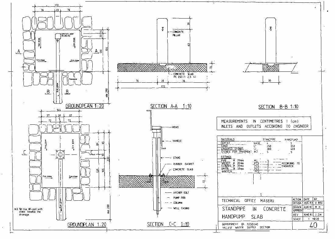
172
FITTINGS
PIPE O 20mm~CKtT 0 20 FIWIOI EL~WS~20mo
_~NIO~j._~20mmBIBCOCK
STAN~P’PE HANOPUMPs250400
76 ,~2O} 76 -_
nC~XrIl. putt20.010.13
11Oc,. 01.9.
1~
AJ
n_ _ W
r~irn~cnnbLDG EbU
--C~P�1EPLLAR
a
, ‘
L CO~(RETEPC 25011
SOAB2.5 4) I
,~, 76 20
172
76
E
141.
6ROUNDPLAN 1:20
si ~o L 57
L
$E~TjON A-A 1:10 SECTION B-B 1:10
~)
72 1 c~ 1 72
DU~D~fl
ri/fl’
e
w j~
rn__D_
MEASUREMENTS IN CENTIMETRES (cm)INLETS AND OUTLETS ACCORDING TO ENGINEER
Zc~. .109. 0cm .Io~.
MATERIALSHAMJL E
STAF~
RUBBER GASKET
CONCRETE SLAB
~JIÇ~T____ SAGS 4SAF~D - LT 250
200STONES FOR PAVEMENT f12 5
NB TRI the I-P-pad wIthslope taw~ds I-he
draEage.
----s-
o
E
GROUNDPLAN 1.20
Ml - 4 ~ -1 _~ACC~D1NG TO
~ 2 ENGINEER-—
PCÇ I
ANCI-BJR 6~T
-
— CŒ.UMN
-— WELL CAS~4G
SECTION C-C
TECHNICAL OFFICE MASERU DATE JOYDESIGN AUG83 U B~i
~ AUGB7M~
I~-~-y---~ Z~
STANDPIPE
HANOPUMP
IN CONCRETE
SLAB SCALE , 1 10/20
1:10 I GOVERTWIEF’T OF LESOTI-tO— — L VIL’.A’IF WATER SUPPLY SECTION —J-J--

CONCRETE PC 250 PRECAST CONCRETE SLAB3) REINFORCED
II 2,5 LI MESH
TOP FLOATED
MA NIELE COVER
AIRATION 050mm
‘.COATS PLASTERIP~
COV HO
ALL CORNERS WITH
SECTION A—A
197ci?2 ~ ~ ~2 SuS
MEASUREMENTS IN CENTIMETRES I (Cm)
INLETS AND OUTLETS ACCORDING TO ENGINEER
A 60 03 63 152 152B 126 126C —— — 79 79 L10’
197 1i97i~~Li~i
FITTINOS
PIPE OSOmm Ml I 1 1PIPE G4Omm Hi 4 L 6~L LPIPE 025mm LOCKPIPE 0 20mm LOCK
MiHT
1F~
1F
~L__-lI~_~i_1 1[i
BIBCOCKS PCS 1 1 1 1 ISOCKETS 020mm LOCKUNION FLAT FACE 0 INLE1
PCSI-~F
2F
2i
2 2 [21
ELBOWS 90°0 50mm pt! 2 2—
2ELBOWS 90°ø2Omm PtÇ i~ 1 f —
ELBOWS 90°ø60mm W D/D P PCS L 4 4ELBOWS 90°0 INLET PtÇ 1 if — i
TEE EDUAL O 2S mm LOCK PtC 2 2 2’’~f2 7PLUD SOLID 060mo pt~ t~
MATERIALSCEMENT BAOS
M3
IS
0,6
17
0,0
16
1,0
21
15
23
1,5
BRICKSSHAPED STONESCRUSHED STONESSANDMESH REF 100RODS 0 0mm
H3 1,5 ,jj_ ~tã~_25 iLHT ~ ~j 12,0 ~ 160MT So i~a~1~I.a~i.ziqPTT 1 1 1 1 1HI 7T1 7,0 ~j WW io.o
C I MANHOLE COVERSAP 15 s 2,5cmSLABFORHWDRKSID�FORHWDRK
PCS 1e_ci_t 1 liii ii~i
G
“r r—
PC 250(1 2,SWITH MESh
LI-k~
— I
ACCDRD*C TONECESSARY
PLA STER INO
CONCRETE PC 25011 2.5 4) • MESH
TOPPING 13WITH CEMENTPASTE
50cm
SECTION B—B
—t
MEASUREMENTS
mY C
AIRATIONO SO mm
LOCK
VOLUME It 500 Iiso 1000 2000 3000
4- -~r ±-—--iI
J~BB j.BK j
.
PT] ~ 750/1000 II
10540M!SOAK AWAY11 50 ,~1 Cr4 PLAN
r~1~I ~ 2000/3O00I~
I IL~J
~66 ,l.oo .1
,
PRECAST SLABS 1 ‘50
TECHNICAL OFFICE
WATER POINTV= 500 /750/1000/
MASERU
2000/300011f
ONDESIGNDRAWN
APPROVREV
SCALE
DATE lotAPR64 H PFDEC 86BUKDEC 66 I M
DEC66 J M1 ‘ 20
GOVERNMENT OF LESOTHO —
VILLAGE WATER SUPPLY SECTION

a
CONCRETE PC 250(1 2,S ‘I
TOPPING 1 3 WITHCEMENT PASTE
OUTLET
- UN13N MESH
SECTION A—A
105
~ ~-F~ ~2ZS~5
MEASUREMENTS IN CENTIMETRES! 1Cm)INLETS AND OUTLETS ACCOROth~TO ENGINEER
C
SECTION A—A SECTION A—A
FITTINGS
œalr
QLI
z
=
Q
-BAFFLE PLATE
OISTRIBUTION—CHAMBZR MAY BE PLPEEO ON TOPOF TANK JWATERPOINT
PIPE 040mm Ml 4_ I. L.PIPE 0 25mo -~-. ~E tPIPE 020mmSOCKETS 9 40 l’a
SOC KETS O 20mm~—
I
t_L J—1~ j_
— L.
-i---~j_J-
UNION FI.ATFACEØLOres 1_
IJNION FLAT FACE O PCS 1 (31 TELBOWS 90 P40mm ~: I i
LET
PIRs~LIcall~th D,—:
BAFFLE PLATE
LOC KLOCK
LOCK
mill F~
OUTLETLOCK
OIJTLET
A
~L6u~oTE~ EQUAL 0 25m,, I~[
1:7
r-tT—T 2
PLUG SOLIO’aLOmr lPcs
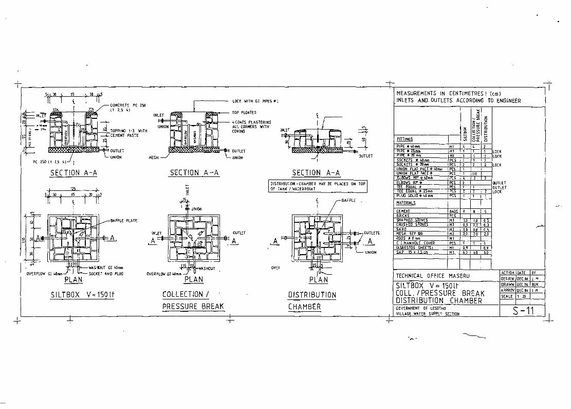
SILTBIJX V~15O1f CdLLECTION
/
PRESSURE BREAK
MATERIALS I J J
CEMENT*~ICKS I P ti0T ~0 1160SRIAPEO STONESCRIJSHEQ $TOFWIS ~j~_ ~9J ~JSANDMESH REF 100 M2 ~,Q~,9RIES OHm,, MlCl MAN t13LE COVER 1 1 1(ASBESTOS SHEETS)SAP 15 • 2.5 cm ~j_ iO. iR QLiL
OVERFLOW SI 40mm WASHOUT 01 40mmSOCKET ANO PU~JO
DISTRIBUTIONCHAMBER
TECHNICAL OFFICE MASERU ACTIONIRATEOESIGN~C~6JM
SILTBOX V 1501f ORAWNOEC86LH
COLL /PRESSURE BREAK APPROVOEC86~M
DISTRIBUTION CHAMBER SCALE 120GOVE~MEHT OF LESOTIIO B — 11VILLAGE WATER SIJPPLY SECJ(PN

a
5k)25J. 36 45 I.Z532Z~1j.511 1 1 1 1 J]
CONCRETE PC 2503.’.
PRECAST CONCRETEINLET ~ 112.5 ‘4-I •MESH
~I0AT — SLAB PC 300 11’ 23)REINFORCED
UNION7 ~ — COATS PLASTERING
ALL CORNERS WITHVI NO
______________________________ OUTLET
MESH -~~-“ L UNION
SECTION A—AT91 V—SOOlt151 V-300II-
5~
106 V- 300 (t L22-5
152 V_500111
UNIONINLET
~UTLET. ____
‘n ~25
IOVERFLOW 6) 40mo ~1“s— WASHOUT G) 4Cmm
PLAN
LOCK WITH G! PIPESO 20mo
MANHOLE COVER
TOP FLOATEO
TOPPING T ‘ 3 WITHCEMENT PASTE
SOCPEE T~PLUG
CONCRETE PC 250112,5 4) WIll-i MESIl
MEASUREMENTS IN CENTIMETRES) (Cm)
INLETS AND OUTLETS ACCORDING TO ENGINEER
F IT T 1140 S
PIPE O 40mm Ml 4
COVING
PIPE 025moPIPE 020mo
~inLL is_SOCKETS O 40mm PCS ISOCKETS O 20mm ~Ç~_ 2UNION PLAT FACE 0 PCSUNION FLAT FACE O PCSELBOWS 90 040mm PCS 3ELBOWS
90ó OTEE EQUALO25mm PCS 2PLUG SOLID 040 mmFLOATVALVE 025/32)40mm PCS
SECTION B—B
LOC KLOCK
LOC KINLETOUTLET
OUTLETLOCK
OUT LETSTRAINER 0 PCS
—~
MATERIALS V 300)1 V—5001FCEMENT I BAGS B T3BRICKS I .ECL !tZL....(SHAPED STONES I j 113CRUSHEO STONES LJ±i_ !~_. Q.L__SAND 113 ~j_ LL_MESH REF 100 112 ~_ 80OQUS O Hmm Mi 5,0
SAP 15 x 2,5cmSLI
SO
HT 60PIS
7.0
TECHNICAL OFFICE MASERU
PRESSURE BREAK TANKWITH FLOATVALVE
~ONOESIGN~APPROV
~REV
GATEJAN84NOVP6BUKNOV06120NOV06
BYH
J M
1M -
GOVERNMENT OF LESOTHO — B—12VILLAGE WATER SUPPLY SECTION
-F

p
MEASUREMENTS VOLUME M3 1 2 3 4 S 7,5 10 1 is
—
3
J
iii. 233 233 260 304 L20 516 606200 I 223
fl iiTr
83 155Th3
223178
731iW
270 264. 600 L9L ISO822S 216 332 L28 S20
263 21.3 263 263- 223 223 223 223
131 176 178 173 178~6 159 iSO lS9~ië~
PG____
‘ 15 15 iS 15 20 20 20 20FITTINGS I~P)PEOSOmm MI 6 6 6 6 6 6 6PIPE O 25mm LDCK Ml 1 1 1 1 1
PIPE 020mm LDCK Ml 1 1 1 1 1 1SDCKETS020mm LOCK PCS 2 2 2 2UNION FLAT PACE 0 PCSELBOWS 90°tSOmm PCS 5 5 5 5 5 5 5 5TEE EOUALO2Smm LOCK PCS 2 2 2 2 2 2 2 J 2PLUG SOLID O W O PCS
—
1E
1~
1~
1~
1~
1~
1 I 1
MATERIALS j
CEMENT BAGS jj iL IL. St—
.5LIiL JLBRICKS PCS 650 850 ~0O 1250 ~00 IQQQ 356PSHAPHED STONES M3
IQO 141CRUSHED STONES M) ~5 iT jj 3 L 5jSAND (jj_ zj jj, jj j,Q~MESM REF 100 M2 flA J2& fl iiLQ iLl &PRODS 0 8mm Ml 12,0 250 22,0 2&0 j~9 14~CI MANHOLECOVER PCS 1 1 1 1 1 1 1 1
SAP lSx 2,Scm Ml IL i~îiLQ uPic,gSAP 23x S,Ocm Ml jj~qjj~p fl,g
SLABPDRMWDRK PCSSIDEFDRMWORK PCS
TECHNICAL OFFICE MASERU ~ MAR
-4-
t:AIR AT(ONc SOn
a
=
COVER
~1~
- TOP FLOATED
IIMLETI
CONCRETE PC 250(1 2,5 L)
MEASUREMENTS IN CENTIMETRES! (CMIINLETS ANO OUTLETS ACCOROING TO ENGINEER j
TANK V—1 —6 M3 1 MESH IN BOTTOM SLAB (TOP ONLY)4.—15M3 2 MESH IN BOTTOMSLAB (TOP AND BOTTOM)
SECTION B-BSECTION A —A
A î __ —n0C fill
I - ~8sj,88j,~
________ 1M3,/ ~ ~ Z’~ --—--- AIRATION 050mm
-~ ~ WASHOUT~ ~s~if~SR SUPPLY
— t\\I ~ ~ A OVERFL~}TO VALVE CHAMBER
4-
PLAN
±±t! SCALE 1 50
41 [II] [fi] [Hifi]41 [[lEI
]
486}2x7 ~ 6x68 -~ 4.861. 5x72 4. 4.004. 7x66 4.
5M3 7,5M3 10 M3 1SM3
PRECAST SLABS SCALE 1 100
STORAGETANK
VOLUME 1 — 15MBGOVERNMENT OF LESDTMO —
VILLAGE WATER SUPPLY SECTION
DRAWN GEC 86 BUKAPPRDV DEC86 I M
SCALE OEC:6 I M
B—20

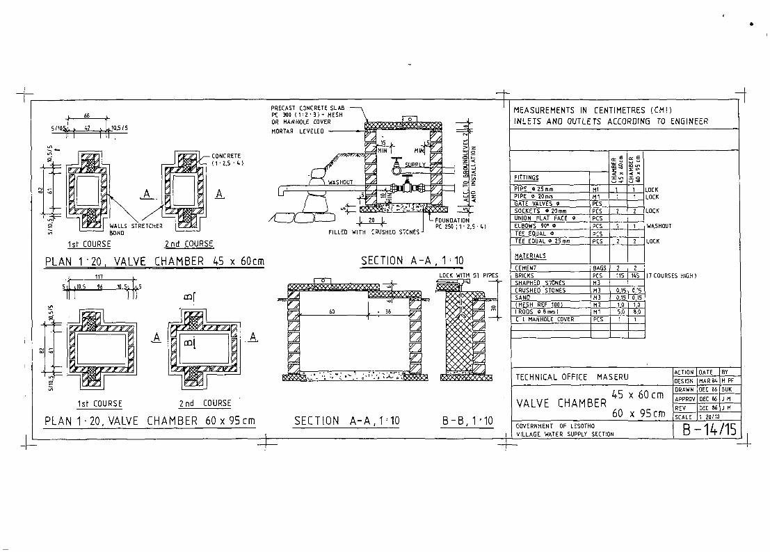
s
GOVERNMENT OF LESOT1IOI VILLAGE WATER SUPPLY SECTION
siio4~ :: ~1:1.10.5/5
g
MEASUREMENTS IN CENTIMETRES (CM))INLETS AND OUTLETS ACCORDING TO ENGINEER
1st COURSE 2nd COURSE
FITTINGS
PLAN 120, VALVE CHAMBER45 x 60cm117
S~~IO.5 96
= ,n
‘n
= o
PIPE 025mm I lii 1 1 111KPIPE O 20mm •~j_~_GATE VALVES ~ [PCS
~.~O~CI(-SO[KFTS 0i~Prnm _~f~SI~
SECTION A—A, 110
L~LK
WASHOUT
LOC K
17 COURSES HIGH I
UNION FLAT FACE Q I PCSELBOWS 90° 0 PCS 1 TTEE EQUAL O PCSTEE EDUAL O 2S mm PCS 2 2
MATERIALS
CEMENT BAGS 2 2BRICKS PCS J~I!~_SHAPHEO STONES 113CRUSHEDSTONESSAND(MESH REF 1001(ROOS 08mm)C I MANHOLECOVER
M3M]~Ml
(ois~
105.0 ~
1st COURSE 2nd COURSE
PLAN 1~20,VALVE CHAMBER 60x95cm SECTION A_A,lhlO B - B, 1 10
TECHNICAL
VALVE
OFFICE MASERU
x 60cmCHAMBER
60 x 95cm
ACTION bArE boYDESiGN MAR 041M PF
DRAWN JOEC 06 rBUKAPPROVIOECB6IJMREV bEC soJi M
SCALE ~20/10
I B—14/15I I

s

T i li
SECTION B-B
PIPEPIPE
0 50mmG IDRAINI
061E VALVE 050mm
MlMI
MATERIALS
CEMENT it~~i5I
,
BRICKS PCS aSIC
20
12017’.1_
SHAPED STONES~ M3
CRUSHED STONES
ROIS 08mm0001 • PRAME STEEL
M)
fijr PCS
7.5
j~j1
ORAIN MESH ~LPCS 2 . zSAP 23.5cm M1I2L ‘26SLABPORMWORK ISIOEPORMWORK _._I_ j I
16018’ 000
‘as 175,5 ç,
~1 H-
86
t”6_t
— _iMEASUREMENTS IN CENTIMETRES’ (CmlINLETS ANO OUTLETS ACCOROING TO ENGINEER
20NIMEASUREMENTS
PITTINDS
30M3562.421 £726
V: 20 /30 M3
TOP OPVALVE CHAMBER
20M3
Lx69,S :278 f
-~--±j
L~ TECHNICAL OFFICE MASERU
1- 7x72:504 -
PRECAST SLABS 1 50
STORAGE TANKVOLUME 20 / 30 M3
ACTION DAlE 81OESK)N APR84 U 6W
DRAWN DEC 86 BaiEAPPRDV DEC 86 J H
REV 0EC86 J H
SCALE 1 20
DOVERNHENT OP LESDTHDviii ~ wx’FR r-~Ofl.Y
R - ‘fl

V

I
CONCRETE PC 250Ils I*MESH~~f î~rwPRECAST CONCRETE ________ ____________ ____SLAB PC 300 Ii ‘Z • 3 _________ - ~REINFORCEO ~1.ET~ -~ ~
ALL C~NERSWITH4 COATS PLASTERING ~ ~COVING
PC 250112.541 ______________ ii~WITH MESH
SECTION A —A151
5d~5L 106 1.~sL~5ii 1 1 11
MEASUREMENTS IN CENTIMETRES (cm)
INLETS AND OUTLETS ACCORDING TO ENGINEER
ç,, ~ç. ~iç • l,Ç , ç ~ç,, ç
‘n
X
LOCK WITH G! PIPES O 2Omm
TOP FLOATED
~— SIDE WALL ACCORDING TO
I TERRAIN IF NECESSARYj1— PLASTERING
]~
FITTINGS
C KETHOLDER IFMORE THAN
50cm
CONCRETE PC 250I 1 ‘ 2,5 41 MESH
PIPE 040mmPIPE 025moPIPE 020mm
u, ç-
BlOCOC K
4
PAVING
SECTION B-B
LOC çLOCK
LOCK
OUTLETL 0(6
SOCKETS 0 20mm :~:UNION FLAT FACE O 40m PCS )ELBOWS 90°040mm
—PCS ~5_
ELBOWS 90°0 20mo PCS 1 -
TEE EQUAL 0 25mmPLLM3 SOLID 0 40mm PCS I —
MATER IALS
CEMENT BAGS 12BRICKS ~QSHAPHED STONES 113CRUSHEDSTONES 113 0,7SAND .itL. .j~Q.
RODS 0 8 mmMESH REF 100 _112_ 7,0
..b11ILK~ ruN SIULWALLS ARE NOT INLLUOED
TECHNICAL OFFICE MASERU~~iONDESIGN
DATEAPR 81.
BYH PF
WATERPOINT V= 300ttDRAWN
REVSCALE
DEC 06
NOV661 20
BUK
1M
GOVERNMENT OF LESOTHOVILLAGE WATER SUPPLY SECTION B-30

-I