Manual - Lo-Lift
20
OPERATION & MAINTENANCE MANUAL P.O. Box 745 Welsh, LA 70591 Phone: (337) 734-3502 Fax: (337) 734-4335
Transcript of Manual - Lo-Lift

OPERATION & MAINTENANCE MANUAL
P.O. Box 745 Welsh, LA 70591
Phone: (337) 734-3502 Fax: (337) 734-4335
i
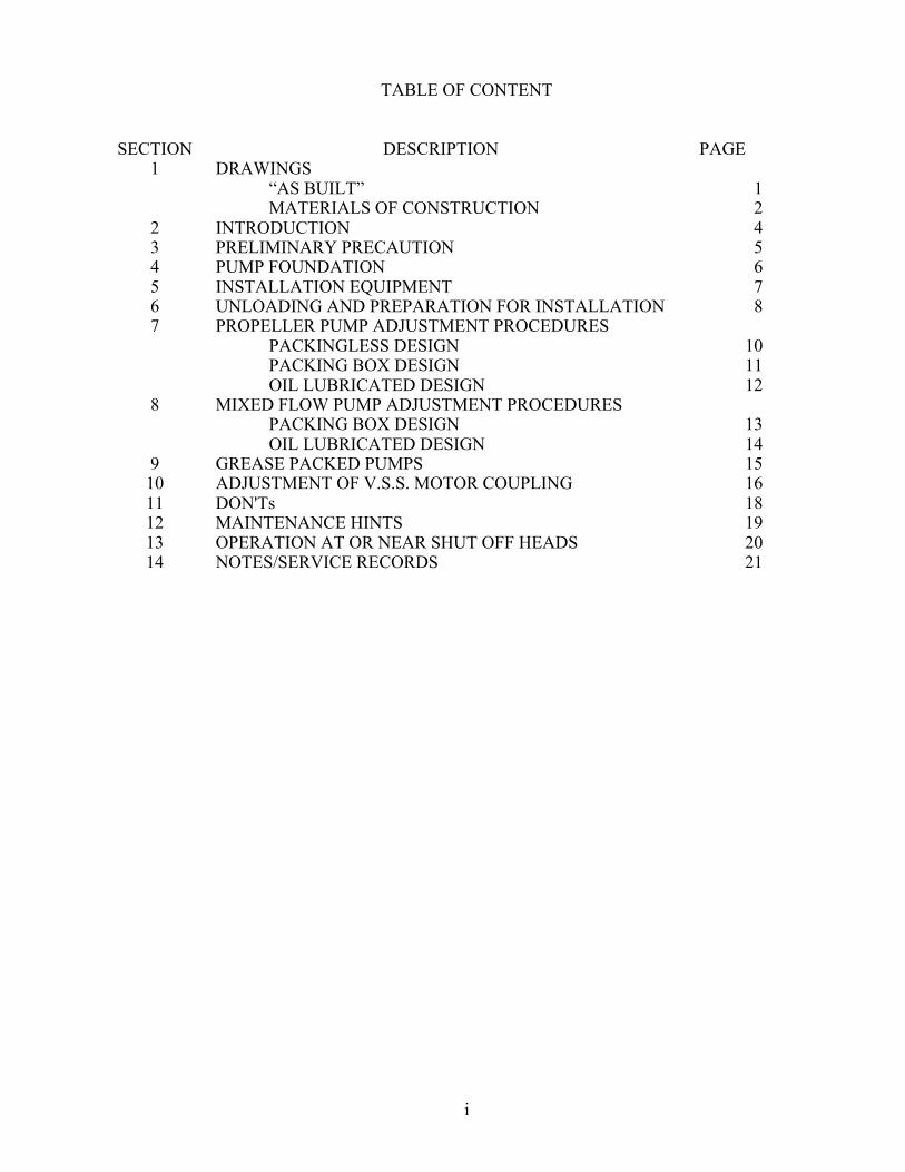
TABLE OF CONTENT
SECTION DESCRIPTION PAGE 1 DRAWINGS “AS BUILT” 1 MATERIALS OF CONSTRUCTION 2 2 INTRODUCTION 4 3 PRELIMINARY PRECAUTION 5 4 PUMP FOUNDATION 6 5 INSTALLATION EQUIPMENT 7 6 UNLOADING AND PREPARATION FOR INSTALLATION 8 7 PROPELLER PUMP ADJUSTMENT PROCEDURES PACKINGLESS DESIGN 10 PACKING BOX DESIGN 11 OIL LUBRICATED DESIGN 12 8 MIXED FLOW PUMP ADJUSTMENT PROCEDURES PACKING BOX DESIGN 13 9
OIL LUBRICATED DESIGN GREASE PACKED PUMPS
14 15
10 ADJUSTMENT OF V.S.S. MOTOR COUPLING 16 11 DON'Ts 18 12 MAINTENANCE HINTS 19 13 OPERATION AT OR NEAR SHUT OFF HEADS 20 14 NOTES/SERVICE RECORDS 21

4
SECTION 2
INTRODUCTION
Your propeller/mixed flow pump is designed and engineered for dependable and durable service. Following these procedures will provide the desired results. The satisfactory operation of the vertical propeller/mixed flow pump is dependent upon careful and correct installation and maintenance of the equipment. Because of the variations in installation requirements, the following instructions must, of necessity, be rather general in tone. The installer and maintenance man must use sound judgment to adapt the methods outlined to the conditions existent for each particular installation. General assemblies of vertical propeller/mixed flow pumps are shown in the following illustrations with the individual parts properly identified. This nomenclature will be used as a reference throughout the instructions. It must be understood that these are typical illustrations and may not conform in complete detail to the equipment as furnished. Please refer to any drawings that have been prepared for this specific installation and become thoroughly familiar with the construction of the pump furnished before attempting to assemble, install, dismantle, or do repair work on the unit. This type of equipment is often furnished with optional features to the specifications of the user. Most of the available options will be described in the booklet. Please refer to those sections applicable to the construction of your unit, disregarding those that do not apply. Close-coupled vertical propeller/mixed flow pump are usually shipped assembled and proper instruction for the handling of this type of machine will be presented here first. For equipment of a length too inconvenient to ship completely joined, the bowl unit and discharge elbow section are assembled individually at the factory while the extra column parts may be shipped as components for job site assembly as suggested later in the following instructions. If there is any doubt or question during the process of installation or operation, contact the factory representative at once.
5
SECTION 3
PRELIMINARY PRECAUTION
Inspect all material and packing for signs of damage in shipment before signing the delivery slip. Any damage should be noted on the delivery slip before signing the release and the carrier’s claims inspector must be summoned. Otherwise, the signed receipt clears the carrier of any responsibility for the condition of the material as received. If any parts are protected with permanent coatings, extreme care in handling will be necessary to prevent damage to coating. This might include such precaution as gloves for wrenches, etc. If coating is damaged, it should be repaired before installation is completed. Examine the installation site carefully before starting work. If pump is to be installed in a sump, be sure sump has been cleared of debris and is equipped with provisions to prevent entrance of any more foreign material. The sump itself, including inflow channel and pump mounting structure, must be of a design adequate for the equipment to be installed. This consideration is the responsibility of the user. During all steps of installation, care must be used to prevent strains from being imposed upon pump parts that might cause bending or misalignment of column or shafting. This also applies to piping connections. The use of a dresser type coupling is recommended to avoid putting the unit is stress with discharge piping makeup.
6
SECTION 4
PUMP FOUNDATION
A suitable pump foundation should always be provided, preferably of solid concrete construction. If this is not practical, adequate beams or timbers may be used. The pump foundation must be built to carry the weight of the entire pump full of liquid and the driver and should be of a design to withstand and prevent undue vibration. If the pump is mounted on beams, the beams should be heavy enough to prevent spring action between spans, also with lateral bracing to prevent side motion. Pump foundation or mounting structure is not to be considered part of the pump and will be the responsibility of the user.

7
SECTION 5
INSTALLATION EQUIPMENT Required installation equipment will of course depend upon type and size of the pump to be installed. Although portable derricks or tripods are sometimes used, a properly designed pump setting rig or construction crane is recommended (figure 1). The lifting device must be of sufficient height to allow the load to be raised about two feet higher than the total length of the unit if it is desired to handle the complete assembly. Depending upon the complexity of the installation, the following miscellaneous tools may be required:
1) Wooden friction blocks or steel clamps (figure 2).
2) Steel column lifting elevators of approved type and of proper size for the pump column.
3) Cable sling approximately 10 feet long and adequate size for the loads involved (figure 3).
4) Two chain tongs. 5) Two medium size pipe wrenches.
6) Twelve foot length of ¾” manilla rope.
7) Ordinary set of mechanic’s tools (figure 4).
8) Wire brush. 9) Paint brush. 10) A good grade of pipe joint
compound. 11) Gasoline, distillate or solvent. 12) Set of eyebolts.
If equipment is to be oil lubricated, provide at least one gallon of SAE #10 mineral oil with proper additives or a good turbine oil such as Texaco Regal 100 R & O. If mating stainless steel parts are to be joined, particularly with threads, a lubricant containing Molybdenum disulphide or some equally effective anti-galling compound should be provided and used per manufacturer’s direction.
Figure 1: Pump Installation Rig Figure 2: Beam Clamps
Figure 3: Cable Sling Figure 4: Ordinary Set of Mechanics Tools

8
SECTION 6
UNLOADING AND PREPARATION FOR INSTALLATION
Uncrate parts and inspect carefully to be sure nothing was damaged in shipment. Check in detail condition of any part of equipment or crating has been damaged or broken in shipment, please report immediately to transportation company involved and to the factory, with full particulars, confirming all verbal understandings by letter. Do not accept shipments showing damage. Be sure to note damage on the freight receipt before signing and request a claims inspector from the delivering carrier. Do not sign for an incomplete shipments of material listed on the Bill of Lading. If pump is shipped unassembled, see Section 9. If not, continue with this section. Clean mounting structure at pump location. Clean bottom face of elbow/pedestal mounting base plate. Raise engine unit as shipped to a vertical position, using proper lifting lugs or eyebolts (figure 5), taking care not to put strain on column or any exposed shafting. Install assembled unit in a plumb vertical position with full contact base to mounting surface. Assemble base plate mounting bolts and/or nuts. If driver is of vertical solid shaft construction, refer to procedures outlined in Section 9. If driver is of vertical hollow shaft construction, continue with this section. Clean all mounting surfaces and lower driver into position atop its mounting structure, fastening with cap screws as provided. Remove canopy and drive coupling, illustrated in figure 10. Check level indicators for amount of oil or grease in driver bearings. Do not add grease without first opening grease relief plugs, as high pressure might damage grease seals. In general, lubrication instructions will be furnished with the driver and these instructions should be followed implicitly. CAUTION: Do not work on pump, motor, wiring, or other components of the system without first opening main breaker or pump disconnect switch. Since many electric motors will be furnished as dual voltage machines, it is important that proper connections be made to suit voltage of power source. Therefore, check power source and motor instruction nameplate for proper method of connecting motor terminals. On electric motor driven units of hollow shaft construction, connect motor terminals to leads in starter panel. Energize starter panel and buzz-start motor by switching it very quickly on and off, observing for proper rotation and inspection to see that it spins freely and is in balance. Motor must run counter-clockwise when viewed from the top. If rotation is clockwise, interchange any two motor connections on three phase motors. On single-phase motors, follow manufacturer’s instructions. After reconnection, again buzz-start the motor to check rotation. Make absolutely sure that it will drive the pump in a counterclockwise direction before making connection to pump shaft. De-energize panel at main breaker or pump disconnect switch before continuing. Assemble head shaft, sliding it down through driver hollow shaft, snapping it to firm butt against pump shaft. If possible, hold shaft coupling by reaching through coupling access opening in elbow/pedestal. Remember shaft threads are left hand. Make sure head shaft stands in the center of the hollow shaft or that a very slight pressure will center it.

9
The drive coupling should have a sliding fit and should be firmly seated in it proper position on top of the driver without tendency to hang up as it is lowered into position or rotated. It must sit perfectly flat and without cocking. Try drive key in head shaft keyway and coupling keyway. Make sure that this is also a sliding fit. Reassemble coupling in place on driver and insert key. Do not force key in place. Dress the key NOT THE KEYWAY until a free but not loose fit has been obtained. Top of key must be below adjusting nut seat when in place. Thread adjusting nut onto head shaft remembering shaft threads are left hand. See figure 12. See section 7 or section 8 for adjustment procedure that should be followed at this time.
Figure 9: Proper Lifting Figure 10: Head Shaft Centering
Figure 11: Adjusting Nut Installation

10
SECTION 7
PROPELLER PUMP ADJUSTMENT PROCEDURE (A) PACKINGLESS DESIGN PROCEDURE (figure 8): A propeller, shown in figure 9, is designed to operate best approximately half way between its upper and lower limits of travel in the cylindrical section of the discharge or intermediate bowl. This design is fairly simple to maintain and consists of three basic components; extractor, ball flange bearing and lip seal. These units are shipped fully assembled from the factory and already have the extractor pre-set. So that the only adjustment required will take place after the driver is in place. Threading the adjusting nut down all the way, tightening until there is a sudden stop and the shaft is frozen. At this point, the extractor is jammed up against the base. The block taped to the shaft above the ball flange bearing should now be removed. The adjusting nut must now be unthreaded about ½ turn in order to allow about 1/16" running clearance. Tighten the allen set screw into place over the keyway. Do NOT tighten it on top of the threads. The ball flange bearing is a self-aligning type and is not designed to carry any thrust. A zerk fitting is provided and should be serviced according to usage.
Figure 8: Packingless Design Figure 9: Propeller

11
(B) PACKING BOX DESIGN (figure 10): A propeller, shown in figure 9, is designed to operate best approximately half way between its upper and lower limits of travel in the cylindrical section of the discharge or intermediate bowl. When a hollow shaft driver is furnished, adjust pump by turning nut on the left hand threads so that the propeller breaks free from the extreme low position. This is the break-free point and should be marked, nut to drive coupling. Then, by continuing to turn the adjusting nut, raise the shaft until propeller contacts the top of propeller cavity in the bowl. Do not use undue force against any resistance. Upper limit of propeller adjustment is thus established and should be marked, again nut to drive coupling. The number of turns of adjusting nut between the two marks should be recorded and nut backed off from its upper position half the total number of turns recorded above. Tighten the allen set screw into place over the keyway. Do NOT tighten it on top of the threads. If a packing box (figure 11) has been furnished, it will usually be shipped assembled in its proper position in the elbow or driver pedestal. Normal packing box assembly will usually include packing box Item G, bushing or throttle sleeve Item J. Immediately above this are assembled a given number of packing rings Item D. Then a lantern ring Item E positioned as to allow leakage into proper drain port, then more packing rings and at the top, packing gland Item C. An "O" Ring Item H seals housing flange to seat. Also supplied is a copper tube with fitting to connect to the packing box. This is to drain the water that comes through the packing box assembly. Grease is not required. At time of first operation, start the pump and run for 10 to 15 minutes. Let pump packing leak at least 100 drops per minute during first operation. If leakage slows down, loosen gland nuts to keep leak rate constant. Gland temperature should level off and then drop slightly toward the end of 15-minute operation. Gland nuts may then be drawn up about 1/6 turn every five minutes until leaking is minimized. If during this operation the gland heats up so that it will vaporize water, back off gland nuts and repeat run-in procedure as described until temperature stays down after gland nuts are re-tightened. Gland nuts must always be rotated evenly to avoid cocking gland
Figure 10: Packing Box Design Figure 11: Packing Box Assembly
12
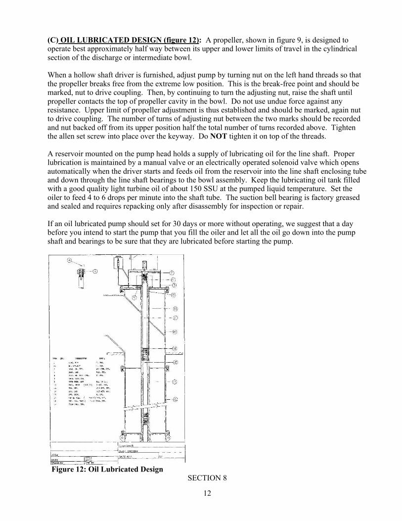
(C) OIL LUBRICATED DESIGN (figure 12): A propeller, shown in figure 9, is designed to operate best approximately half way between its upper and lower limits of travel in the cylindrical section of the discharge or intermediate bowl. When a hollow shaft driver is furnished, adjust pump by turning nut on the left hand threads so that the propeller breaks free from the extreme low position. This is the break-free point and should be marked, nut to drive coupling. Then, by continuing to turn the adjusting nut, raise the shaft until propeller contacts the top of propeller cavity in the bowl. Do not use undue force against any resistance. Upper limit of propeller adjustment is thus established and should be marked, again nut to drive coupling. The number of turns of adjusting nut between the two marks should be recorded and nut backed off from its upper position half the total number of turns recorded above. Tighten the allen set screw into place over the keyway. Do NOT tighten it on top of the threads. A reservoir mounted on the pump head holds a supply of lubricating oil for the line shaft. Proper lubrication is maintained by a manual valve or an electrically operated solenoid valve which opens automatically when the driver starts and feeds oil from the reservoir into the line shaft enclosing tube and down through the line shaft bearings to the bowl assembly. Keep the lubricating oil tank filled with a good quality light turbine oil of about 150 SSU at the pumped liquid temperature. Set the oiler to feed 4 to 6 drops per minute into the shaft tube. The suction bell bearing is factory greased and sealed and requires repacking only after disassembly for inspection or repair. If an oil lubricated pump should set for 30 days or more without operating, we suggest that a day before you intend to start the pump that you fill the oiler and let all the oil go down into the pump shaft and bearings to be sure that they are lubricated before starting the pump.
Figure 12: Oil Lubricated Design
SECTION 8

13
MIXED FLOW PUMP ADJUSTMENT PROCEDURE
(A) PACKING BOX DESIGN (figure 10): The impeller (figure 13) is designed to operate close to the taper bowl seat in the intermediate bowl or suction bell (figure 14) for best performance. With a hollow shaft driver, adjust by turning the adjusting nut on the left hand shaft threads so that the impeller just breaks free from the seat. This is the break-free point and should be marked, nut to driver coupling. Then continue to turn the adjusting nut until the impeller clears the seat, approximately ¼ turn (*) of the adjusting nut. Rotate the shaft to make sure it will turn freely. On settings beyond 20 feet in length, increase this clearance ¼ turn of the adjusting nut for each additional 20 feet of column length. Tighten the allen set screw into place over the keyway. Do NOT tighten it on top of the threads. It should be noted that hydraulic down thrust increases with operating pressure. While shaft elongation on close coupled and very short pumps is minimal, it must be remembered that some deflection will occur, however minor. Pumps that must be subjected to varying operating heads should be adjusted with respect to the highest head to avoid excessive dragging of impellers under these conditions. If a packing box has been furnished (Fig. 11), it will usually be shipped assembled in its proper position in the elbow or driver pedestal. Normal packing box assembly will usually include packing box Item G, bushing or throttle sleeve Item J. Immediately above this are assembled a given number of packing rings Item D. Then a lantern ring Item E positioned as to allow leakage into proper drain port, then more packing rings and at the top, packing gland Item C. An "O" Ring Item H seals housing flange to seat. Also supplied is a copper tube with fitting to connect to the packing box. This is to drain the water that comes through the packing box assembly. Grease is not required. At time of first operation, start the pump and run for 10 to 15 minutes. Let pump packing leak at least 100 drops per minute during first operation. If leakage slows down, loosen gland nuts to keep leak rate constant. Gland temperature should level off and then drop slightly toward the end of 15-minute operation. Gland nuts may then be drawn up about 1/6 turn every five minutes until leaking is minimized. If during this operation the gland heats up so that it will vaporize water, back off gland nuts and repeat run-in procedure as described until temperature stays down after gland nuts are re-tightened. Gland nuts must always be rotated evenly to avoid cocking gland.
Figure 13: Impeller Figure 14: Seated Impeller * FOR MFK MODELS ONLY: Turn the adjusting nut until the impeller clears the seat by
approximately 3/8”. The impeller can be adjusted up or down to fine tune the operation point.
14
(B) OIL LUBRICATED DESIGN (figure 12): The impeller (figure 13) is designed to operate close to the taper bowl seat in the intermediate bowl or suction bell (figure 14) for best performance. With a hollow shaft driver, adjust by turning the adjusting nut on the left hand shaft threads so that the impeller just breaks free from the seat. This is the break-free point and should be marked, nut to driver coupling. Then continue to turn the adjusting nut until the impeller clears the seat, approximately ¼ (*) turn of the adjusting nut. Rotate the shaft to make sure it will turn freely. On settings beyond 20 feet in length, increase this clearance ¼ turn of the adjusting nut for each additional 20 feet of column length. Tighten the allen set screw into place over the keyway. Do NOT tighten it on top of the threads. It should be noted that hydraulic down thrust increases with operating pressure. While shaft elongation on close coupled and very short pumps is minimal, it must be remembered that some deflection will occur, however minor. Pumps that must be subjected to varying operating heads should be adjusted with respect to the highest head to avoid excessive dragging of impellers under these conditions. A reservoir mounted on the pump head hold a supply of lubricating oil for the line shaft. Proper lubrication is maintained by a manual valve or an electrically operated solenoid valve which opens automatically when the driver starts and feeds oil from the reservoir into the line shaft enclosing tube and down through the line shaft bearings to the bowl assembly. Keep the lubricating oil tank filled with a good quality light turbine oil of about 150 SSU at the pumped liquid temperature. Set the oiler to feed 4 to 6 drops per minute into the shaft tube. The suction bell bearing is factory greased and sealed and requires repacking only after disassembly for inspection or repair. If an oil lubricated pump should set for 30 days or more without operating, we suggest that a day before you intend to start the pump that you fill the oiler and let all the oil go down into the pump shaft and bearings to be sure that they are lubricated before starting the pump. * FOR MFK MODELS ONLY: Turn the adjusting nut until the impeller clears the seat by
approximately 3/8”. The impeller can be adjusted up or down to fine tune the operation point

15
SECTION 9
GREASE PACKED PUMPS *Please refer to oil lubricated design for adjustment procedure. See table below for greasing schedule. Heavy duty, multi-purpose, lithium grease is recommended for use in the grease packed pumps. Lip seals located in the pump are rated for 50 P.S.I.
Shaft Diameter (in.) Amount Per Bearing (oz.) Frequency (Hrs.)
1.25 2 36
1.50 2 30
1.94 3 25
2.19 3 22
2.44 4 24
3.00 6 24

16
SECTION 10
ADJUSTMENT OF SOLID SHAFT COUPLING
Figure 15: Typical Solid Shaft Coupling
1. Clean driver mounting flange on discharge head and check for burrs or nicks on the register
and mounting face. Oil lightly. 2. Clean top shaft threads and lubricate with light oil. Check threads by screwing coupling
adjusting nut (#126) onto top shaft. Remove nut from shaft. 3. Lift driver and clean mounting flange and check for burrs or nicks. Check mounting register
diameter of driver with discharge head. 4. Install driver half-coupling on the driver shaft. See figure 17.
A. Place straight key (#121) into keyway. Key should clear circular keyway near end of shaft.
B. Slide driver hub (#120) onto shaft far enough to insert the split ring halves (#122) into the circular keyway.
C. Install split rings and slide pump hub down over the split rings. The pump hub will then retain the split rings in position. When properly located, the driver hub flange should be slightly below the driver shaft.
5. Install pump hub (#127) onto top shaft. A. Slide pump hub onto shaft. B. Install pump key (130) into pump hub enough to clear threads. NOTE: check for
presence of dowel pin (#131). C. Thread adjusting nut onto top shaft until end of shaft is even with top of adjusting nut.
6. Center driver over pump and rotate to align mounting holes. A. Electric motors – rotate junction box to desired position B. Gear drivers – rotate input shaft to desired position.
7. Lower driver carefully into position. 8. Bolt driver to discharge head. 9. Check driver manufacturer’s instructions for special instructions including lubrication and
start-up instructions.
17
10. Electric motors should e checked for proper rotation. Make electrical connections and jog motor momentarily to check rotation. CAUTION: Before jogging motor, make sure coupling hub and adjusting nut are not touching and that the driver can rotate freely without rotating the pump. Driver hub must be in proper position (see figure 17) so that the split rings will not come out.
11. After proper rotation of driver is confirmed, complete coupling assembly. 12. If the coupling uses a spacer, bolt the spacer to the driver hub. 13. Thread adjusting nut to proper impeller setting which is measured between the adjusting nut
and spacer or driver hub. 14. Slide pump hub up shaft and align adjusting nut bolt holes with those in pump hub. Rotate
driver shaft until bolts can be inserted through driver hub, pump hub, and adjusting nut. 15. Tighten all bolts evenly. This will raise impeller to correct operating position.
18
SECTION 11
DON’T s DON’T pull discharge piping to pump discharge flange with bolts or cap screws. Install pipeline so
that fasteners are used to prevent leakage only. DON’T hang weight of discharge line and fittings on discharge elbow alone. Support pipeline by
blocking or concrete saddles according to best piping practice. Use dresser-type couplings wherever possible to eliminate piping strains imposed on pump.
DON’T start pump while it is rotating in reverse direction after having shut down. It is advisable to
install a delay relay on electric drives to prevent this. Non-reverse protection in driver could also be a solution.
DON’T put heavier than recommended heaters in starter if pump load begins to trip those furnished
originally. These are protective devices. DON’T add oil to driver while running. DON’T add grease to grease lubricated driver without
removing relief plug. DON’T drop parts into pump during installation or disassembly. DON’T drop parts into motor when
canopy has been removed and top is open. Parts must be removed before next operation. DON’T tighten shaft packing where provided except in increment, i.e., tighten gland nuts part of a
turn and let pump run 5-10 minutes before tightening further. If leakage water is too hot to put on hand, back gland nuts off a little until water cools, then tighten again. Gland nuts must be adjusted evenly so as to prevent cocking gland, forcing it against shaft.
DON’T forget that this equipment contains rotation parts. Use CAUTION when working near such
parts to avoid injury. DON’T neglect guards, covers, and shields before start-up. DON’T run pump backward. Clockwise operation (looking down on pump) under power can
unscrew threaded joints. Power requirements of impellers can increase when driven backward and can thus create undesirable overloads. These problems do not apply to pump coasting backward due to return flow of water from system.
DON’T throttle the suction of the pump or operate with restricted suction since power will increase
and delivery will be reduced. DON’T change pump speed without checking effect on power, internal pressure and other
conditions. DON’T allow oil, grease, or thread lubricant to contact rubber bearings. DON’T work on pump, wiring, or any system components without opening energizing circuits such
as at main breaker or pump disconnect switch. This will prevent “surprise” starts that may occur due to automatic control systems.
SECTION 12

19
MAINTENANCE HINTS For pump lubrication, use light turbine oil equivalent to Standard Oil O.C. Turbine Oil #9 or good grade of mineral oil with proper additives having viscosity equal to 150 SSU at the pumped liquid temperature. Remove old oil from driver once a year, flush with solvent and refill. Follow manufacture’s instructions carefully as to method and type of lubricant. Replace self-lubricated driver ball bearings in about 5 years. It is generally less expensive to replace these bearings before they fail. Routinely check for any unusual noise or vibration. Inspect all shafts, bearings, propeller, and clearances anytime the pump is open. Replace as needed. Replace all shaft packing on open line shaft pumps after maintenance has required addition of two rings. Always let packing box leak slightly at top to add life to packing. If packing box is leaking excessively, replace all packing. Inspect bearing in packing box every 12 months, replace if worn. When pump is not running, verify shaft is turning freely every 3-6 months. Be aware of changing conditions in the system. Any change from original conditions or any variation in the system can create an undesirable reaction in pump as the energizer of the system. Refer to vertical turbine pump association environmental data brochure for some of the system variable conditions that might occur or for recommendations due to a system change, consult the factory. Don’t attempt to remove or to repair your pump without consulting a company representative. If it becomes necessary to attempt any repair work on your equipment, be sure to review all instructions for operation and maintenance of the unit.

20
SECTION 13
OPERATION AT OR NEAR SHUT OFF HEADS Normally the operating of propeller/mixed flow pumps in NOT recommended at or near shut off or static flow heads. Operation should be limited to the highest head shown on pump curve or field curve that has been submitted. At no time should the driver be overloaded beyond normal service factor unless approval has been given and the duration for a short period only. The maximum head operating condition should include the following considerations:
A.) Thrust bearing capacity must be adequate. B.) If prolonged operation at no flow or restricted delivery is contemplated, the problem of
heat dissipation may become acute. Much of the power under such conditions in converted to heat in the available fluid.
C.) Propeller and mixed flow impellers have critical horsepower characteristics at low flows. Shut off power requirements will in most cases result in driver overload.
D.) It must be kept in mind that open line shaft units depend upon pump fluid for lubrication. Fluid temperatures, if raised excessively due to lack of flow, may impair lubrication efficiency.
Full operation range should be known and considered in the original pump and driver selection. In the event of a change in conditions, contact a factory representative for recommendations.

21
NOTES
SERVICE RECORDS