Manual Fiac Airblock 20
35
1/36 PRODUCT SERVICE GB USE AND MAINTENANCE MANUAL SILENT ELECTRIC ROTARY SCREW COMPRESSORS WARNING: Read this manual carefully and in full before using the compressor.
-
Upload
titus-dulacioiu -
Category
Documents
-
view
1.789 -
download
10
Transcript of Manual Fiac Airblock 20

1/36
PRODUCT SERVICE
�������������� ���� ���� �� �
GB
USE AND MAINTENANCE MANUALSILENT ELECTRIC ROTARY SCREW COMPRESSORS
WARNING: Read this manual carefully and in full before using the compressor.

2/36
IMPORTANT INFORMATIONRead all the operational instructions, safety recommendations and all warnings provided in the instruction manual.Most accidents encountered when using the compressor are merely due to the failed observance of basic safetystandards.Accidents are prevented by foreseeing potentially hazardous situations and observing the appropriate safetystandards.The fundamental safety standards are listed in the “SAFETY” section of this manual and also in the section involvingthe use and maintenance of the compressor.Hazardous situations to be avoided in order to prevent serious personal injuries and machine damages are listed inthe “WARNINGS” section of the instruction manual or are actually printed on the machine.Never use the compressor improperly but only as recommended by the Manufacturer.The Manufacturer reserves the right to up-date the technical information given in this manual without notice.

3/36
GBINDEX I
I Index
0 Foreword ......................................................................................... 50.1 How to read and use the instruction manual ............................................. 50.1.a Importance of the manual .................................................................................................... 50.1.b Conserving the manual ........................................................................................................ 50.1.c Consulting the manual ......................................................................................................... 50.1.d Symbols used ........................................................................................................................ 6
1 General information........................................................................ 71.1 Identification data of the manufacturer and the compressor ................... 71.2 Information on machine technical/maintenance service .......................... 71.3 General safety warnings .............................................................................. 7
2 Preliminary machine information ................................................ 102.1 General description .................................................................................... 102.2 Intended use ................................................................................................ 102.3 Technical data ............................................................................................. 11
3 Transport, Handling, Storage ...................................................... 123.1 Transporting and handling the packed machine ..................................... 123.2 Packing and unpacking .............................................................................. 123.3 Storing the packed and unpacked compressor ....................................... 13
4 Installation ..................................................................................... 144.1 Admitted surrounding conditions ............................................................. 144.2 Space required for maintenance ............................................................... 144.3 Positioning the compressor ...................................................................... 154.4 Connecting the compressor to the sources of energy and relative inspections . 154.4.1 Connecting the compressor to the electrical mains power supply ................................ 154.4.2 Connecting the dryer to the electrical mains .................................................................... 17
5 Using the compressor .................................................................. 185.1 Preparing to use the compressor .............................................................. 185.1.1 Operational principle .......................................................................................................... 18
5.2 Controls, indicators and safety devices of the compressor ................... 195.2.1 Control panel ....................................................................................................................... 195.2.2 Auxiliary control devices.................................................................................................... 19
5.3 Check the efficiency of the safety devices before starting ..................... 215.4 Starting the compressor ............................................................................ 215.5 Stopping the compressor .......................................................................... 22

4/36
GB I INDEX
6 Compressor maintenance............................................................ 236.1 Instructions relative to inspections and maintenance jobs. ................... 236.1.1 Changing the oil .................................................................................................................. 266.1.2 Replacing the oil filter cartridge ........................................................................................ 276.1.3 Replacing the filter cartridge of the oil separator ............................................................ 276.1.4 Replacing the air filter cartridge ........................................................................................ 276.1.5 Tightening the belt .............................................................................................................. 286.1.6 Replacing the belt ............................................................................................................... 286.7.7 Cleaning the air/oil radiator ................................................................................................ 286.7.8 Cleaning the dust-removal pre-filter ................................................................................. 286.1.9 Lubricating the electric motor ........................................................................................... 28
6.2 Diagnosing the alarm status/inconveniences-faults ............................... 29
7 Drawings and diagrams ............................................................... 307.1 Wiring diagrams .......................................................................................... 307.2 Pneumatic diagrams ................................................................................... 317.3 Spare parts table7.4 Kit assembling table7.5 Maintenance schedule

5/36
FOREWORD 0 GB
0 Foreword
0.1 How to read and use the instruction manual
0.1.a Importance of the manual
This INSTRUCTION MANUAL has been written to guide you through the INSTALLATION, USE andMAINTENANCE of the compressor purchased.We recommend that you strictly observe all the indications given within as the ideal operational efficiencyand lasting wear of the compressor depend on the correct use and methodical application of themaintenance instructions given hereafter.Remember that when any doubts or inconveniences arise it is a good rule to always contact theAUTHORISED SERVICE CENTRES. They are at your complete disposal for any explanations or jobsrequired.The Manufacturer therefore declines all liabilities regarding the incorrect use and poor maintenance of thecompressor.The INSTRUCTION MANUAL is integral part of the compressor.Ensure that any up-dates forwarded by the Manufacturer are actually added to the manual.If the compressor is sold on at a later date the manual must be given to the new owner.
0.1.b Conserving the manual
Use and read the manual with care being careful not to damage any part of it.Do not remove, tear or re-write any parts of the manual for any reason whatsoever.Keep the manual in a dry and sheltered place.
0.1.c Consulting the manual
This instruction manual is made up of the following:
• FRONT COVER WITH MACHINE IDENTIFICATION• DETAILED INDEX• INSTRUCTIONS AND/OR NOTES ON THE COMPRESSOR
The model and serial number of the compressor to which the manual refers and that you have purchasedis found on the FRONT COVER.The various SECTIONS in which all the notes relative to a certain subject are found in the INDEX.All the INSTRUCTIONS AND/OR NOTES ON THE COMPRESSOR aim at pointing out safety warnings andprocedures required to use the compressor correctly.

6/36
GB 0 FOREWORD
0.1.d Symbols used
The SYMBOLS pointed out below are used throughout this manual and their purpose is that of drawing theoperator’s attention, informing the latter how to behave and how to proceed in each operational situation.
READ THE INSTRUCTION MANUALRead the use and maintenance manual carefully before installing and starting thecompressor.
GENERAL HAZARDOUS SITUATIONAn additional note will point out the type of hazard involved.Meaning of the indications:
Warning! This points out a potentially hazardous situation, which if ignored, could cause personalinjury and machine damage.
Note! This enhances crucial information.
RISK OF ELECTRIC SHOCKWarning: the electrical power supply of the compressor must be disconnected before doingany jobs on the compressor.
RISK OF SCOLDINGWarning: be careful when touching the compressor as some parts of it could be very hot.

7/36
GBGENERAL INFORMATION 1
1 General information
1.1 Identification data of the manufacturer and the compressor
COMPRESSORIDENTIFICATIONNAMEPLATE (Example)
Silent electric rotary screwcompressor.
1.2 Information on machine technical/maintenance service
We remind you that our technical service department is at your complete disposal to help you resolve anyproblems that may possibly be encountered, or to provide you with any other information necessary.
In the case of need contact:
Our CUSTOMER TECHNICAL SERVICE department or your local dealer.
The constant and efficient performance of the compressor is ensured only if original spare parts are used.
We recommend therefore that you strictly observe the indications provided in the MAINTENANCE sectionand to use EXCLUSIVELY original spare parts.
The use of NON ORIGINAL spare parts automatically annuls the guarantee.
1.3 General safety warnings
Note! The procedures provided in this manual have been written to assist the operatorthroughout the use and maintenance of the compressor.
IMPORTANT INSTRUCTIONS FOR THE SAFE USE OF THE COMPRESSOR
WARNING: THE INAPPROPRIATE USE AND POOR MAINTENANCE OF THIS COMPRESSOR MAYCAUSE PHYSICAL INJURY TO THE USER. YOU ARE RECOMMENDED TO CAREFULLY FOLLOWTHE INSTRUCTIONS PROVIDED HEREAFTER TO AVOID SUCH RISKS.
1. DO NOT TOUCH MOVING PARTSNever put your hands, fingers or other parts of the body near moving parts of the compressor.

8/36
GB 1 GENERAL INFORMATION
2. NEVER USE THE COMPRESSOR WITHOUT THE SAFETY GUARDS FITTEDNever use the compressor without all the safety guards fitted perfectly in their correct place (i.e. panelling,belt guard, safety valve). If these parts are to be removed for maintenance or servicing purposes, ensurethat they are put back in their original place perfectly before using the compressor again.3. ALWAYS WEAR SAFETY GOGGLESAlways wear goggles or equivalent eye protection means. Never direct compressed air towards any part ofyour body or that of others.4. PROTECT YOURSELF AGAINST ELECTRIC SHOCKSAvoid accidentally touching the metal parts of the compressor with your body, such as pipes, the tank ormetal parts connected to earth. Never use the compressor where there is water or in damp rooms.5. DISCONNECT THE COMPRESSORDisconnect the compressor from the electric power supply and completely discharge the pressure from thetank before carrying out any service, inspection, maintenance, cleaning, replacing or inspection jobs of eachpart.6. ACCIDENTAL START-UPNever move the compressor while it is connected to the electrical power supply or when the tank ispressurised. Ensure that the main switch is turned OFF before connecting the compressor to the electricalpower supply.7. STORE THE COMPRESSOR APPROPRIATELYWhen the compressor is not in use, it must be stored in a dry room away from atmospheric agents. Keepit out of children’s reach.8. OPERATIONAL AREAKeep the work area clean and remove any tools that are not required. Keep the work area sufficientlyventilated. Never use the compressor in the presence of flammable liquids or gas. The compressor mayproduce sparks while running. Do not use the compressor where there may be paints, gasoline, chemicalcompounds, glues and any other flammable or explosive material.9. KEEP THE COMPRESSOR OUT OF CHILDREN’S REACHPrevent children or anyone else from touching the power supply cable of the compressor. All outsiders mustbe kept at a safe distance from the operational area.10.WORK CLOTHESDo not wear unsuitable clothing, ties or jewellery as these may get caught up in moving parts. Wear capsto cover your hair if necessary.11.PRECAUTIONS FOR THE POWER SUPPLY CABLEDo not disconnect the power supply plug by pulling on the cable. Keep the cable away from heat, oil and sharpedges. Do not stand on the electrical cable or squash it under heavy weights.12.LOOK AFTER THE COMPRESSOR WITH CAREFollow the maintenance instructions. Inspect the power supply cable on a periodic basis and if damaged itmust be repaired or replaced by an authorised service centre. Visually check the outside appearance of thecompressor, ensuring that there are no visual anomalies. Contact your nearest service centre if necessary.13.ELECTRICAL EXTENSIONS FOR OUTDOOR USEWhen the compressor is used outdoors, use only electrical extensions manufactured for outdoor use andmarked as such.14.WARNINGPay attention to everything you do. Use your common sense.Do not use the compressor if you are tired. The compressor must never be used if you are under the effectof alcohol, drugs or medicines, which could make you tired.15.CHECK FAULTY PARTS OR AIR LEAKSBefore using the compressor again, if a safety guard or other parts are damaged, they must be checkedcarefully to evaluate whether they may operate as established in complete safety.Check the alignment of moving parts, hoses, gauges, pressure reducers, pneumatic connections and everyother part that may be crucial for the normal operational efficiency of the compressor. All damaged partsmust be properly repaired or replaced by an authorised service centre or replaced following the instructionsprovided in instruction manual.16.USE THE COMPRESSOR EXCLUSIVELY FOR THE APPLICATIONS SPECIFIED IN THISINSTRUCTION MANUAL.The compressor is a machine that produces compressed air.Never use the compressor for purposes other than those specified in the instruction manual.17.USE THE COMPRESSOR CORRECTLYOperate the compressor in compliance with the instructions provided in this manual. Do not allow childrento use the compressor or those who are not familiar with it.18.ENSURE THAT EACH SCREW, BOLT AND GUARD IS FIRMLY SECURED IN PLACE.

9/36
GBGENERAL INFORMATION 1
19.KEEP THE IN-TAKE GRIDS CLEANKeep the motor ventilation grids clean. Regularly clean these grids if the work area is particularly dirty.20.OPERATE THE COMPRESSOR AT THE RATED VOLTAGEOperate the compressor at the voltage indicated on the electric data nameplate. If the compressor is usedat a higher voltage than that rated, the motor will run faster, thus it could be damaged or could burn-out.21.NEVER USE THE COMPRESSOR IF IT IS FAULTYIf the compressor is noisy or vibrates excessively when running or it seems to be faulty, stop it immediatelyand check its efficiency or contact your nearest authorised service centre.22.DO NOT CLEAN PLASTIC PARTS USING SOLVENTSSolvents such as gasoline, thinners, gas oil or other compounds that contain hydrocarbons may damagethe plastic parts. Clean them with a soft cloth and soapy water or other suitable liquids.23.USE ORGINAL SPARE PARTS ONLYThe use of non-original spare parts involves the annulment of the guarantee and the abnormal runningconditions of the compressor. Original spare parts are available c/o the authorised dealers.24.DO NOT MODIFY THE COMPRESSORDo not modify the compressor. Contact an authorised service centre for all repairs required. An unauthorisedmodification may impair the efficiency of the compressor and may also cause serious accidents for thosewho do not have the technical skill required to make such modifications.25.TURN THE COMPRESSOR OFF WHEN IT IS NOT IN USEWhen the compressor is not in use turn the main ON/OFF switch OFF (position “0”).26.DO NOT TOUCH HOT PARTS OF THE COMPRESSORTo avoid scolding do not touch pipes, the motor or any other hot part.27.DO NOT DIRECT THE JET OF AIR DIRECTLY TOWARDS THE BODYTo avoid all risks never direct the jet of air towards people or animals.28.DO NOT STOP THE COMPRESSOR BY PULLING ON THE POWER SUPPLY CABLEUse the “O/I” (ON/OFF) switch to stop the compressor.29.PNEUMATIC CIRCUITUse recommended pneumatic hoses and tools that can withstand the same or a higher pressure than themaximum running pressure of the compressor.30.SPARE PARTSUse only original and identical spare parts to replace worn or damaged ones.Repairs must be made exclusively by authorised service centres.31.CORRECT USE OF THE COMPRESSORThe operator must be perfectly familiar with all the controls and compressor characteristics before startingto work with the machine.32.MAINTENANCE JOBSThe use and maintenance jobs of the commercial components fitted on the machine, but not indicated inthis manual, are indicated in the enclosed documents.33.DO NOT UNSCREW THE CONNECTION WHEN THE TANK IS PRESSURISEDDo not unscrew the connection for any reason whatsoever with the tank pressurised without first checkingif the tank is discharged.34.DO NOT MODIFY THE TANKIt is prohibited to intentionally drill, weld or deform the compressed air tank.35.IF THE COMPRESSOR IS USED FOR PAINTING JOBSa) Do not work in closed rooms or near free flames.b) Ensure that the room in which you are working is sufficiently ventilated.c) Wear face and nose mask.36.DO NOT PUT OBJECTS OR HANDS INSIDE THE PROTECTION GRIDDo not put objects or hands inside the protection grid to avoid physical and material damages.
KEEP THESE USE AND MAINTENANCE INSTRUCTIONS CAREFULLY AND GIVETHEM TO PERSONNEL WISHING TO USE THE COMPRESSOR!
WE RESERVE THE RIGHT TO MAKE MODIFICATIONS WHERE NECESSARYWITHOUT NOTICE

10/36
GB 2 PRELIMINARY MACHINE INFORMATION
2 Preliminary machine information
2.1 General description
The rotary screw compressor has been specifically designed aiming at minimising maintenance andlabour costs.The outside cabinet is completely covered in sound-proof and oil-proof panelling thus ensuring its extendedand lasting wear.The components have been arranged so that all vital parts can be easily reached for maintenance purposessimply by opening dedicated panels with quick-release locking devices.The filters and adjustment and safety devices (oil filter, air filter, oil separator filter, regulator valve, minimumpressure valve, max. pressure safety valve, thermostat, belt tightener, screw compression unit, pressureswitch and oil separator tank emptying and filling taps) are all fitted on the same side.
Note! The tanks of the compressors have been manufactured in compliance with the EEC/404/87 Directive for the European market.The compressors have been manufactured in compliance with the EC/37/98 Directivefor the European market.
Note! Check your model on the identification nameplate fitted on the compressor. It is alsoindicated in this manual.
ADVISED LUBRICANTSAlways use oil for turbines with approximately 46 cSt at 40°C and a pour point of at least -8 +10°C. Theflash point must be greater than +200°C.
NEVER MIX DIFFERENT OIL QUALITIES.
SCREW OILESSO EXXCOLUB 46BP ENERGOL HLP 46SHELL CORENA D 46TOTAL AZOLLA ZS 46MOBIL DTE OIL 25DUCKHAMS ZIRCON 46
Use oil with VG32 rating for cold climates and VG68 for tropical climates.It is advisable to use synthetic oils for very hot and humid climates.
2.2 Intended use
The silent rotary screw compressors have been designed and manufactured exclusively to produce compressed air.EVERY OTHER USE, DIFFERENT AND NOT FORESEEN BY ALL INDICATED, RELIEVES THEMANUFACTURER OF POSSIBLE CONSEQUENT RISKS.In any event the use of the compressor different to that agreed in the purchase order RELIEVES THEMANUFACTURER FROM ALL LIABILITIES WITH REGARD TO POSSIBLE MATERIAL DAMAGE ANDPERSONAL INJURY.The electrical system is not designed for the use in environments subject to explosion or for flammable products.
NEVER DIRECT THE JET OF AIR TOWARDS PEOPLE OR ANIMALS. NEVER USETHE COMPRESSED AIR PRODUCED BY LUBRICATED COMPRESSORS FORRESPIRATORY PURPOSES OR IN PRODUCTION PROCESSES WHERE THE AIR ISIN DIRECT CONTACT WITH FOODSTUFFS UNLESS IT HAS BEEN FIRST FILTEREDAND CONDITIONED FOR SUCH PURPOSE.

11/36
IPRELIMINARY MACHINE INFORMATION 2
HP
10H
P15
HP
20H
P25
HP
30
bar
/psi
8-11
610
-145
13-1
888-
116
10-1
4513
-188
8-11
610
-145
13-1
888-
116
10-1
4513
-188
8-11
610
-145
13-1
88
RC
B60
RC
B60
RC
B10
1R
C B
101
RC
B10
1
min
-144
7039
2033
1060
3052
0042
3039
3034
2028
6547
3641
0435
1055
1049
9040
40
l/min
1180
980
800
1630
1400
1150
2350
2000
1450
2850
2490
1853
3054
2779
2250
cfm
41,6
34,5
28,2
57,5
49,4
40,6
8370
,661
,710
0,6
87,9
65,4
113,
810
3,1
83,3
R3/
4 G
3/4
G3/
4 G
3/4
G3/
4 G
3/4
G3/
4 G
3/4
G3/
4 G
1 G
1 G
1 G
1 G
1 G
1 G
l7,
57,
57,
57,
57,
57,
57,
57,
57,
59,
59,
59,
59,
59,
59,
5
m3 /
h25
0025
0025
0025
0025
0025
0042
0042
0042
0048
0048
0048
0050
0050
0050
00
pp
m<
3<
3<
3<
3<
3<
3<
3<
3<
3<
3<
3<
3<
3<
3<
3
IEC
MEC
132M
EC13
2MEC
132
MEC
132
MEC
132
MEC
132
MEC
132
MEC
132
MEC
132
MEC
160
MEC
160
MEC
160
MEC
160
MEC
160
MEC
160
HP
/kW
10/7
,510
/7,5
10/7
,515
/11
15/1
115
/11
20/1
520
/15
20/1
525
/18,
525
/18,
525
/18,
530
/22
30/2
230
/22
IP54
5454
5454
5454
5454
5555
5555
5555
S 1
S 1
S 1
S 1
S 1
S 1
S 1
S 1
S 1
S1
S1
S1
S1
S1
S1
N°
1010
1010
1010
1010
1010
1010
1010
10
°C (
min
/max
)5/
455/
455/
455/
455/
455/
455/
455/
455/
455/
455/
455/
455/
455/
455/
45
dB
(A)
6565
6567
6767
6868
6869
6969
7070
70
2.3
Tec
hn
ical
dat
a
Mo
del
Max
. pre
ssur
e
Typ
e of
rot
ary
scre
w e
nd
Com
pres
sor
rota
tion
spee
d
Fre
e ai
r de
liver
y IS
O 1
217
Air
outle
t fit
ting
Lubr
ican
t qt
y
Fan
cap
acity
Oil
resi
due
in a
ir
2-po
le e
lect
ric m
otor
Out
put
Inpu
t
Pro
tect
ion
ratin
g
Ser
vice
Max
. sta
rts
per
hour
Am
bien
t te
mpe
ratu
re li
mits
Noi
se le
vel
Sou
nd le
vel m
easu
red
in a
free
ran
ge a
t a d
ista
nce
of 1
m: ±
3dB
(A)
at th
e m
axim
um w
orki
ng p
ress
ure.
The
sou
nd le
vel m
ay in
crea
se b
y 1
to 1
0 dB
(A)
depe
ndin
g on
the
room
in w
hich
the
com
pres
sor
is in
stal
led.
No
te!
Th
e te
chn
ical
dat
a an
d d
imen
sio
ns
of
the
mac
hin
e ar
e su
bje
ct t
o v
aria
tio
ns
at a
ny
tim
e w
ith
ou
t n
oti
ce

12/36
GB 3 TRANSPORT, HANDLING, STORAGE
3 Transport, Handling, Storage
In order to use the compressor in complete safety read the safety standards givenin section 1.3. before reading this section.
3.1 Transporting and handling the packed machine
The packed compressor must be transported by qualified personnel using a forklifttruck.
Before moving the machine ensure that the load-bearing capacity of the forklift truck is sufficient to take theweight to be lifted.Position the forks exclusively as illustrated below. Once the forks have been positioned in the pointsindicated, lift slowly without jerking.
Never stand near the area where the compressor is being handled and never standon the crate while it is being moved.
3.2 Packing and unpacking
To avoid damages and to protect the compressor during transport it is usually placed on a wooden pallet,to which it is secured by screws and covered with cardboard.All the shipping and handling information and symbols are printed on the compressor packing. Uponconsignment remove the top part of the packing and check if any damages have been encountered duringtransport. If any damages are found, caused during transport, immediately make a written claim, backedup with photos of the damaged parts if possible and forward everything to your insurance company, with copyto the Manufacturer and transporter.

13/36
GBTRANSPORT, HANDLING, STORAGE 3
1
2
Using a forklift truck take the compressor as near as possible to the place where it is to be installed thencarefully remove the protective packing without damaging it, following the instructions below:• Remove the packing 1, by sliding it away upwards.• Unscrew screws 2 that block the feet that secure the compressor to the pallet (only for models with tank).
Note! The compressor can be left on the packing pallet to make it easier to move.
Carefully ensure that the contents correspond with all written in the consignment documents. Dispose ofthe packing in compliance with current standards in force in the country of installation.
Note! The machine must be unpacked by qualified personnel using appropriate tools andequipment.
3.3 Storing the packed and unpacked compressor
For the whole time that the compressor is not used before unpacking it, store it in a dry place at a temperaturebetween +5°C and + 45°C and sheltered away from weather.For the whole time that the compressor is not used after unpacking it, while waiting to start it up or due toproduction stoppages, place sheets over it to protect it from dust, which may settle on the components.The oil is to be replaced and the operational efficiency of the compressor is to be checked if it is not usedfor long periods.

14/36
GB 4 INSTALLATION
4 Installation
In order to use the compressor in complete safety read the safety standards givenin section 1.3. before reading this section.
4.1 Admitted surrounding conditions
Position the machine as established when the order was placed. Failing this the Manufacturer is not liablefor any inconveniences that may possibly arise.Unless pointed out otherwise when placing the order, the compressor must work regularly in the surroundingconditions indicated below:ROOM TEMPERATUREThe room temperature must not be lower than 5°C or higher than 45°C to ensure the ideal operationalefficiency of the compressor.If the compressor works at a room temperature lower than the minimum value, the condensate could beseparated within the circuit and therefore the water would mix with the oil, thus deteriorating the quality ofthe latter, failing to guarantee the even formation of the lubricating film between the moving parts with thepossibility of seizure.If the compressor works at a room temperature higher than maximum value, the compressor would takein air that is too hot, which would prevent the heat exchanger from adequately cooling the oil in the circuit,raising the working temperature of the machine, thus causing the thermal safety device to trip, which stopsthe compressor due to an excessive temperature of the air/oil mixture at the screw outlet.The maximum temperature of the room is to be measured while the compressor is running.LIGHTINGThe compressor has been designed in compliance with legal prescriptions and in the attempt to minimiseshadow zones to facilitate the operator’s job.The lighting system of the factory is to be considered as crucial for the operator’s safety.The room in which the compressor is installed must have no shadow zones, dazzling lights or stroboscopiceffects due to the lighting.ATMOSPHERE WITH RISK OF EXPLOSION AND/OR FIREThe standard compressor is not pre-arranged or designed to work in rooms subject to the risk of explosionor fire. The performance of the compressor may decrease at the maximum permitted ambient temperature,with relative humidity higher than 80% and at an altitude of more than 1,000 mt.
4.2 Space required for maintenance
The compressor must be installed in a large room that is well-aired, dust-free and sheltered away from rainand frost. The compressor takes in a large amount of air that is required to ventilate it internally. A dustyatmosphere would in time cause damages and inefficient performance.Part of the dust once inside is taken in by the air filter causing it to clog rapidly and another part of dust willsettle on the components and will be blown against the cooling radiator, consequently compromising theefficiency of the heat exchanger. It is therefore obvious that the cleanliness of the area in which thecompressor is installed is crucial for the correct efficiency of the machine, avoiding excessive running andmaintenance costs. To facilitate maintenance jobs and to create a favourable circulation of air, thecompressor must have a sufficient free space all around it (see fig.).

15/36
GBINSTALLATION 4
2
1
The room must be provided with outlets that lead outdoors near the floor and ceiling that will allow the naturalcirculation of air. If this is impossible, some fans or extractors must be fitted to ensure an air flow rate 20%higher than the cooling air flow rate. Minimum recommended fan capacity: 2500 m3/h.Ducts for the inlet and outlet of the air can be used in unfavourable environments. These ducts must be thesame size as the in-take and delivery grid. If these ducts are longer than 3 meters contact the AuthorisedService Centre.
Note! A conveyance system can be fitted to recover the hot ventilation air delivered, whichcan be used to heat the room or for other purposes. It is crucial that the cross sectionof the system that recovers the hot air is greater than the total cross section of thegrid slots plus the system must be equipped with a forced extraction system(extractor fan) to favour a constant downflow. (minimum cross section 1200 cm²).
4.3 Positioning the compressor
Once the position in which the compressor is to be installed has been identified ensure that the compressoris set on a flat surface.No special foundations or bases are required for the machine.Lift the compressor using a forklift truck (forks at least 900 mm long) and fit the vibration-damping feet 1 andblock with the nuts 2 under the four resting points where established.
Do not secure the compressor rigidly to the floor.
4.4 Connecting the compressor to the sources of energy and relative inspections.
4.4.1 Connecting the compressor to the electrical mains power supply
The compressor is to be connected to the electrical mains by the customer, to hisexclusive liability, employing specialised personnel and in compliance with theAccident Prevention Norms EN 60204.
INSTRUCTIONS FOR CONNECTING TO EARTHThis compressor must be connected to earth while in use in order to safeguard the operator against electricalshocks. The electrical connection must be carried out by a skilled engineer. It is advisable never to dismantlethe compressor or even to make any other connections. All repairs must be carried out exclusively byauthorised service centres or other qualified centres. The earth wire of the power supply cable of thecompressor must be connected only and exclusively to the PE pin of the terminal board of the actualcompressor. Before replacing the plug of the power supply cable ensure that the earth wire is connected.EXTENSION CABLEUse only extension cables with plug and earth connection. Never use damaged or squashed extensioncables. Ensure that the extension cable is in a good state of wear. When using an extension cable, ensure

16/36
GB 4 INSTALLATION
1
that the cross section of the cable is sufficient to convey the current absorbed by the product to beconnected.If the extension cable is too thin there could be drops in voltage and therefore loss in power and overheatingof the equipment. The extension cable of the three-phase compressors must have a cross section inproportion with its length: see table below:
CORRECT CROSS SECTION FOR THE MAXIMIM LENGTH OF 20M220/240V 380/415V
HP kW 50/60 Hz 50/60 Hz3 ph 3 ph
10 7.5 10 mm² 4 mm²15 11 16 mm² 10 mm²20 15 25 mm² 16 mm²25 18 35 mm² 16 mm²30 22 50 mm² 25 mm²
Avoid all risks of electrical shocks. Never use the compressor with damagedelectrical cables or extension cables. Regularly check the electrical cables.Never use the compressor in or near water or near a hazardous area where electricalshocks may be encountered
ELECTRICAL CONNECTIONThe three-phase compressors (L1+L2+L3+PE) must be installed by a qualified engineer. The three-phasecompressors are supplied without plug and cable. The power supply cable must be fed into the electricalcabinet through the dedicated cable clamps 1 situated on the left side of the compressor.
Ensure that the cable cannot accidentally come into contact with moving or hot components, possiblysecure with clips. The cross section of the wires of the power supply cable (for lengths of 4 m and ambienttemperatures of 50°C at the most) must be as follows:
Power Hp Rated voltage 380/415V Rated voltage 220/240V
10 4 mm² 6 mm²15 6 mm² 10 mm²20 10 mm² 16 mm²25 10 mm² 25 mm²30 16 mm² 35 mm²
It is advisable to install the connector, magneto thermal switch and fuses near the compressor (3 m awayat the most). The magneto thermal switch and the fuses must have the characteristics indicated in the tablebelow:
Power Hp Rated voltage 380/415V Rated voltage 220/240VMagneto thermal switch Fuse Magneto thermal switch Fuse
10 25 A 30 A 40 A 40 A15 40 A 40 A 63 A 80 A20 50 A 50 A 80 A 80 A25 63 A 63 A 80 A 100 A30 80 A 80 A 125 A 125 A
Note! The fuse parameters indicated in the table above refer to the gl type (standard). If cartridgefuses type aM are used (delayed) the parameters in the table are to be reduced by 20%.The parameters of the magneto thermal switches refer to switches type K.

17/36
GBINSTALLATION 4
1
2
3
1
Ensure that the installed power in kW is at least double the input of the electric motor. All silent rotaryscrew compressors avail of Star/Delta starting, which enables the motor to start with as little electricalenergy consumption upon start-up as possible.The mains voltage must correspond with that indicated on the electrical data nameplate of the machine;the admitted tolerance must remain within +/- 5%.EXAMPLE:Voltage, 400 Volt: minimum tolerance 380 Volt - maximum tolerance 420 Volt
The plug of the power supply cable must never be used as a switch but must be plugged into a powersocket that is controlled by an adequate differential switch (magneto thermal switch).
Never use the earth connection instead of the neutral. The earth connection must beachieved according to the EN 60204 industrial safety standards.Ensure that the mains voltage corresponds with that required for the correctoperation of the compressor.
CHECK THE ROTATION DIRECTIONWhen connecting the compressor to the electrical mains for the first time ensure that the STOP ALARM isnot triggered, which is pointed out by the red LED lit steady, by a buzzer and by a warning on the display 1stating: ROTATION ALARM.This alarm points out the incorrect connection order of the electrical power supply cables (relative to the threephases) that causes the incorrect rotation direction of the screw unit. Once the cable connection has beenrectified press the RESET key 3.
Warning! The incorrect rotation direction for more than 20 seconds will irreparably damage thecompressor.
4.4.2 Connecting to the pneumatic mains
Always use pneumatic hoses for compressed air with the maximum pressurecharacteristics and cross section suitable for those of the compressor.Do not try to repair a faulty hose.
Connect the compressor to the pneumatic mains using the fitting 1 pre-arranged on the compressor. Usehosing with a greater or same diameter as the compressor outlet. Install two ball taps with capacity suitablefor the compressor between the compressor and tank and between the tank and line. Do not install non-return valves between compressor and tank. The non-return valve is already installed inside the compressor.

18/36
GB 5 USING THE COMPRESSOR
5 Using the compressor
In order to use the compressor in complete safety read the safety standards givenin section 1.3. before reading this section.
5.1 Preparing to use the compressor
5.1.1 Operational principle
The air taken-in by the filter passes through a valve that controls its flow rate to the screw where, mixing withthe oil, it is compressed.The air/oil mix produced by compression reaches a tank where the initial separation by gravity is achieved;as the oil is heavier, it settles on the bottom, it is then cooled and sent through a heat exchanger, filtered andinjected into the screw again.The oil is required to reduce the heat produced by compression, to lubricate the bearings and to maintainthe coupling of the screw lobes. The air is sent through an oil separator filter to be additionally purified fromresidue oil particles. It is cooled by means of another heat exchanger and is finally outlet to be used at lowtemperature and with acceptable water and oil residues (-3p.p.m.). A safety system controls the crucialpoints of the machine and points out any abnormal conditions. The temperature of the air/oil mix at the screwoutlet is controlled by a thermostatic probe, which stops the compressor if the temperature is too high(105°C).A thermal protection device is fitted on the electric motor, which stops the machine if necessary.

19/36
GBUSING THE COMPRESSOR 5
1
2
3
4 5
6
7
8
910
11
1
2
3
5.2 Controls, indicators and safety devices of the compressor
5.2.1 Control panel
The control panel is made up of a set of buttons required for the main operational and control functions ofthe compressor.1 GREEN LED
This points out that the compressor is powered.2 START (I)
This button is used to turn the compressor on.3 STOP (O)
This button is used to turn the compressor off.4 PUSH BUTTON CONTROL PANEL
This is used to program the compressor.5 DEFAULT
Compressor programming is exited by pressing this push button.6 PROGRAM
Programming is enabled by pressing this push button.7 MENU SCROLLING PUSH BUTTON
These four push buttons are used to scroll the menus displayed.8 RESET
Any procedure being performed is cancelled by pressing this push button.9 RED LED
This points out that an alarm has tripped.10 DIGITAL DISPLAY
The various menus are displayed and the parameters are monitored in this display.11 EMERGENCY PUSH BUTTON
This mechanically blocking push button is used to immediately stop the compressor in the case ofemergency. With the push button blocked it is impossible to start the compressor. To be able to start thecompressor again, turn and pull the emergency push button up then press the RESET button.
5.2.2 Auxiliary control devices
1 AIR CIRCUIT PRESSURE CONTROL GAUGE2 OIL THERMAL PROTECTION SWITCH RESET BUTTONThis is positioned on the side of the electrical cabinet inside the compressor.Press this button to reset the oil thermal protection switch.3 MOTOR THERMAL PROTECTION SWITCH RESET BUTTONThis is positioned inside the electrical cabinet.Press this button to reset the motor thermal protection switch.

20/36
GB 5 USING THE COMPRESSOR
CHECKING THE SETTINGS ON THE CONTROL PANELWhen the compressor is ready “PRESS START TO START” appears on the display. The general settingsof the control unit can be checked using the MENU SCROLLING PUSH BUTTONS and the following willappear on the display: “AL TEMPERATURE (105°)”, “TYPE OF SENSOR (17.8)”, SELECT LANGUAGE(0-4) (I)”, “SELECT PSI/BAR 2/1 (BAR)”, “SELECT FAHR./CELS 2/1 (CELS)”, C.R. (2/1) (Y/N) (NO)”,“ALARM PRESSURE (10.5)”, STAR-DELTA T (4)”, “IDLE RUN T (240)”, “SET-UP CLI.P.MAX (10.0)”,SETUP CLI.MIN(8-0)”, MAINTENANCE T (3000)”, TEMPER.ALARM NO. 2”, PRESSURE ALARM NO.0”, THERM.PROT.ALARM NO. 1”, RUNNING HOURS (150), “HOURS OF COMPRESSION (100)”.
Note! Refer to the menu descriptions for the meaning of the parameters indicated above.
Press the DEFAULT key to exit this function.The total running hours (R.H), the hours of compression (H.C.) and the time left to the next maintenanceinterval (MAINT.) can be displayed for a few seconds by pressing the left and right arrow keys together atthe same time.
MENUS THAT CAN BE ACCESSED BY THE CUSTOMER:PASSWORD MENU TO ACCESS TO EXIT
“12” AUTO TEST Keys 1 and 2 pressed together STOP (O) Key“92” CUSTOMER Keys 9 and 2 pressed together DEFAULT Key
AUTO-TEST MENU (12)To enter the Auto-test menu press keys 1 and 2 of the PUSH BUTTON CONTROL PANEL together at thesame time.The Auto-test function automatically checks the electrical connections of the machine. “TEST RUNNING,PRESS STOP TO EXIT” appears on the display.To exit from the Auto-test function press the STOP push button as indicated on the display.
CUSTOMER MENU (92)To enter the Customer menu press keys 9 and 2 of the PUSH BUTTON CONTROL PANEL together at thesame time.The Customer menu is used to calibrate the following parameters:• Cut-in pressure (min.P) of the compressor• Cut-off pressure (max.P) of the compressor• Idle running Time.
To scroll the parameters shown on the display use the arrow keys to scroll the menus and press theDEFAULT key to exit.To modify the min.P value enter the new value in decimals, without comma, then press PROGRAM (i.e. toset 7,5 bar, type-in 75).To modify the max.P value enter the new value in decimals, without comma, then press PROGRAM.Note!: Max.P must be at least 0.5 bar/7.2 psi less than the alarm P.
Max.P - min. P must be higher than or equal to 1 bar/14.5 psi.
To modify the idle running time of the compressor in seconds, enter the new value (in seconds) and thenpress PROGRAM.Note! The minimum idle running time is 120 seconds and the maximum time is 600 seconds.Press the DEFAULT key to exit from the menu.
ALARMSThe alarms that may possibly occur are grouped in two categories:• Stop ALARM (Red LED lit steady)• Warning ALARM (Red LED flashing)
STOP ALARMThis type of alarm stops and blocks the compressor. It is pointed out by the red LED lit steady (ALARM),by a buzzer and by a flashing warning on the display pointing out the cause for the alarm itself.
Pressure alarmWhen the Pressure exceeds the limit alarm Pressure (this may occur if the pressure rises so rapidly thatthe max. cut-off Pressure fails to trip), the following appears on the display:“PRESSURE ALARM”The compressor stops. Once the Pressure drops (P<alarm.P) press RESET to set the compressor ready

21/36
GBUSING THE COMPRESSOR 5
to start again and at this stage the following appears on the display:“PRESS START TO START”
Temperature alarmWhen the maximum oil-air temperature is exceeded (T>105°C/221°F) the following appears on the display:“TEMPERATURE ALARM”The compressor stops. To reset the machine proceed as follows:• Press the oil thermal protection switch RESET push button situated inside the compressor in the in-between
panel after the temperature has dropped by at least 10°C/18°F compared to the maximum temperature.• Then press the RESET key in the control panel.
Thermal protection alarmWhen the electric motor overheats the following appears on the display:“THERMAL PROTECTION ALARM”The compressor stops. To reset the machine proceed as follows:• Open the electrical cabinet and press the RESET push button.• Then press the RESET key in the control panel.
Rotation alarmThe compressor does not start. This alarm points out that the machine has been incorrectly connected tothe electrical mains.Rectify the connection.
WARNING ALARMThis type of alarm does not stop the compressor. It is pointed out by the red LED that flashes (ALARM onfront control panel), by a buzzer and a warning on the display pointing out the warning.“MAINTENANCE TIME WARNING”This points out that the pre-set time for maintenance has expired. The compressor must be serviced.
5.3 Check the efficiency of the safety devices before starting
OIL LEVELCheck the oil level as indicated in Section 6 “Compressor maintenance”.
DO NOT START THE COMPRESSOR WITH THE GUARDS OPEN TO AVOID INJURYDUE TO MOVING COMPONENTS OR ELECTRICALLY POWERED EQUIPMENT.
5.4 Starting the compressor
Following an electrical shortage the compressor will start only if the START (I) buttonis pressed.Ventilation must occur as illustrated below.It is of crucial importance that the compressor works withall the panels firmly closed.The failed observance of these and the following standardsmay lead to accidents that could cause personal injury andserious damages to the compressor or its equipment.
22/36
GB 5 USING THE COMPRESSOR
1
Before initially starting the compressor or following extended inoperative periods, start the machineintermittently by pressing the START(I)-STOP(O) buttons on and off for 3 or 4 seconds. After this it isadvisable to run the compressor for a few minutes with the air outlet tap open. Then gradually shut-off theair tap and load to maximum pressure, checking if the inputs on each phase of the power supply are withinthe limits and also if the pressure switch trips. At this stage ensure that the compressor runs idle for roughly4 minutes. The pressure on the gauge on the panel must be between 2 and 3 bar. After this amount of timethe compressor will stop as the timer will trip. Discharge the air from the tank until the starting pressure isreached (2 bar difference compared to maximum pressure). Shut-off the air outlet tap and wait for thepressure switch to trip, which will shut-on the in-take valve and close the internal discharge.
CALIBRATION AND SETTINGS MADE BY THE MANUFACTURERThe thermal relay is set according to the table below:
Power Hp Rated voltage 380/415V-3ph Rated voltage 220/240V-3ph
10 9 A 15,5 A15 13,5 A 23,3 A20 17,2 A 30,4 A25 22 A 38,2 A30 25,4 A 43,9 A
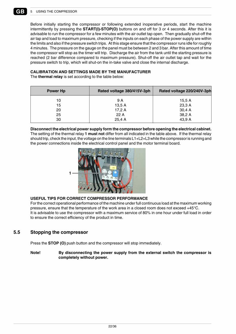
Disconnect the electrical power supply form the compressor before opening the electrical cabinet.The setting of the thermal relay 1 must not differ from all indicated in the table above. If the thermal relayshould trip, check the input, the voltage on the line terminals L1+L2+L3 while the compressor is running andthe power connections inside the electrical control panel and the motor terminal board.
USEFUL TIPS FOR CORRECT COMPRESSOR PERFORMANCEFor the correct operational performance of the machine under full continuous load at the maximum workingpressure, ensure that the temperature of the work area in a closed room does not exceed +45°C.It is advisable to use the compressor with a maximum service of 80% in one hour under full load in orderto ensure the correct efficiency of the product in time.
5.5 Stopping the compressor
Press the STOP (O) push button and the compressor will stop immediately.
Note! By disconnecting the power supply from the external switch the compressor iscompletely without power.

23/36
GBCOMPRESSOR MAINTENANCE 6
6 Compressor maintenance
In order to use the compressor in complete safety read the safety standards givenin section 1.3. before reading this section.
6.1 Instructions relative to inspections and maintenance jobs.
The table that follows summarises the periodic and preventative maintenance jobs required to keep thecompressor in an efficient operational state in time.A brief description of the running hours after which the type of maintenance job is required.
Before performing any jobs within the sound-proof cabinet, ensure that:• The main line switch is turned off (position “0”)• The electrical compressor switch is Off in position “0”• The compressor is disconnected from the compressed air system• All the pressure has been released from the compressor and internal pneumatic circuit.
The compressor has been especially designed to facilitate maintenance jobs by simply opening the sidepanel with quick-release locks.
Weekly: it is advisable to inspect the compressor, paying special attention to oil leaks and scale due to settleddust and oil.
Note! If the compressor is used for more than 3000 hours/year the jobs indicated herewithare to be performed more often.

24/36
GB 6 COMPRESSOR MAINTENANCE
Interval(hours)
500
2500÷3000
5000÷6000
8000÷9000
11000÷12000
Jobsto be performed
Change the oil .......................................................................Replace the oil filter cartridge ................................................Tighten screws, cables, remote switches K1-K2-K3 ..............Tighten the belt ......................................................................Check hydraulic seals ............................................................
Change the oil .......................................................................Replace the oil filter cartridge ................................................Replace the filter cartridge of the oil separator ......................Replace the air filter cartridge ...............................................Tighten screws, cables, remote switches K1-K2-K3 ..............Clean the air/oil radiator .........................................................Clean the dust-removal pre-filter ...........................................
Change the oil .......................................................................Replace the oil filter cartridge ................................................Replace the filter cartridge of the oil separator ......................Replace the air filter cartridge ................................................Tighten screws, cables, remote switches K1-K2-K3 ..............Tighten the belt ......................................................................Check the hydraulic seals ......................................................Overhaul the in-take valve .....................................................Clean the air/oil radiator .........................................................Clean the dust-removal pre-filter ...........................................Test the motor thermal protection switch ...............................Test the oil thermal protection switch.....................................
Change the oil .......................................................................Replace the oil filter cartridge ................................................Replace the filter cartridge of the oil separator ......................Replace the air filter cartridge ................................................Tighten screws, cables, remote switches K1-K2-K3 ..............Replace the belt .....................................................................Check the hydraulic seals ......................................................Clean the air/oil radiator .........................................................Clean the dust-removal pre-filter ...........................................
Change the oil .......................................................................Replace the oil filter cartridge ................................................Replace the filter cartridge of the oil separator ......................Replace the air filter cartridge ...............................................Tighten screws, cables, remote switches K1-K2-K3 ..............Tighten the beltCheck the hydraulic seals ......................................................Check flexible hoses and replace if necessary ......................Overhaul the oil separator flange ...........................................Lubricate the minimum pressure valve ..................................Overhaul the in-take valve .....................................................Clean the air/oil radiator .........................................................Clean the dust-removal pre-filter ...........................................Replace the Rilsan hoses 6x4 and 8x10 ................................Replace screw oil guard ........................................................Maintenance the electric motor ..............................................
Seesection
6.1.16.1.2
6.1.5
6.1.16.1.26.1.36.1.4
6.1.76.1.8
6.1.16.1.26.1.36.1.4
6.1.5
6.1.76.1.8
6.1.16.1.26.1.36.1.4
6.1.6
6.1.76.1.8
6.1.16.1.26.1.36.1.4
6.1.6
6.1.76.1.8
6.1.9

25/36
GBCOMPRESSOR MAINTENANCE 6
The above described maintenance schedule has been planned bearing in mind all the installationparameters and recommended use of the Manufacturer.
The Manufacturer advises the customer to keep a record of all maintenance jobs performed on thecompressor, see Section 7 – Drawings and diagrams.
Interval(hours)
14000÷15000
17000÷18000
20000÷21000
23000÷24000
Jobsto be performed
Change the oil .......................................................................Replace the oil filter cartridge ................................................Replace the filter cartridge of the oil separator ......................Replace the air filter cartridge ................................................Tighten screws, cables, remote switches K1-K2-K3 ..............Check LEDs ..........................................................................Check cables .........................................................................Tighten the belt ......................................................................Check the hydraulic seals ......................................................Replace OR on delivery flange ..............................................Tighten screws ......................................................................Check cooling fans ................................................................Clean the air/oil radiator .........................................................Clean the dust-removal pre-filter ...........................................Clean the compressor ...........................................................
Change the oil .......................................................................Replace the oil filter cartridge ................................................Replace the filter cartridge of the oil separator ......................Replace the air filter cartridge ................................................Tighten screws, cables, remote switches K1-K2-K3 ..............Replace the belt .....................................................................Check the hydraulic seals ......................................................Overhaul in-take valve ...........................................................Clean the air/oil radiator .........................................................Clean the dust-removal pre-filter ...........................................
Change the oil .......................................................................Replace the oil filter cartridge ................................................Replace the filter cartridge of the oil separator ......................Replace the air filter cartridge ................................................Tighten screws, cables, remote switches K1-K2-K3 ..............Check the hydraulic seals ......................................................Replace bearings and screw oil guard ...................................Maintenance the electric motor ..............................................
Change the oil .......................................................................Replace the oil filter cartridge ................................................Replace the filter cartridge of the oil separator ......................Replace the air filter cartridge ................................................Tighten screws, cables, remote switches K1-K2-K3 ..............Tighten the belt ......................................................................Replace flexible hoses ...........................................................Clean air/oil radiator...............................................................
Seesection
6.1.16.1.26.1.36.1.4
6.1.5
6.1.76.1.8
6.1.16.1.26.1.36.1.4
6.1.6
6.1.76.1.8
6.1.16.1.26.1.36.1.4
6.1.9
6.1.16.1.26.1.36.1.4
6.1.5
6.1.7

26/36
GB 6 COMPRESSOR MAINTENANCE
4
3
1
2
6.1.1 Changing the oil
Read all the information provided in Section 6.1 before proceeding with any maintenance jobs.Change the oil following the initial 500 hours of use and then every 2500/300 hours and in event once ayear.Open the top and front panels to access inside the compressor.Unscrew the red cap 1 on the bottom of the screw unit.Take cap 2 off.Screw the knurled fitting 3 (supplied with the compressor).
As the knurled fitting 1 is turned oil starts to seep out from the screw unit, thereforeuse a hose and container to collect the oil.
Once all the oil has been drained remove the knurled fitting 3 and screw cap 2 manually.Fill-up with oil up to the rim of the port 4, then re-screw the dedicated cap 1 back in place and close thecompressor.Once the oil and oil filter have been changed leave the compressor to run for roughly 5 minutes then turnit off and check the oil level again.Check the oil level each month and check that it is up to the rim of the port 4.
Never mix different types of oil, therefore always ensure that the circuit is completely emptybefore filling-up with oil. Each time the oil is changed the filter is also to be replaced.

27/36
GBCOMPRESSOR MAINTENANCE 6
12
1
2
6.1.2 Replacing the oil filter cartridge
Read all indicated in Section 6.1 before starting any maintenance jobs.Replace the oil filter cartridge after the first 500 hours of use then every 2500 hours and in any event eachtime the oil is changed.Open the front panel.Disassemble filter cartridge 1, using a chain spanner and replace with a new one.Lubricate the sealing gasket before screwing the filter cartridge tight.Manually tighten the new filter cartridge.
6.1.3 Replacing the filter cartridge of the oil separator
Read all indicated in Section 6.1 before starting any maintenance jobs.Open the front panel to gain access to inside the compressor.Disassemble filter cartridge 1, using a chain spanner and replace with a new one.Lubricate the sealing gasket before screwing the filter cartridge tight.Manually tighten the new filter cartridge.
6.1.4 Replacing the air filter cartridge
Read all indicated in Section 6.1 before starting any maintenance jobs.Open the top panel to access inside the compressor.Unscrew the cover 1 anti-clockwise.Replace the air filter cartridge 2 and fit the cover back in place by screwing it clockwise.

28/36
GB 6 COMPRESSOR MAINTENANCE
1
12
6.1.5 Tightening the belt
Read all indicated in Section 6.1 before starting any maintenance jobs.Open the side right panel to gain access to inside the compressor.Every 500 hours of use it is advisable to check and maybe tighten the belt if necessary.Using a dynamo meter apply a perpendicular force in point A of between 25N and 35N, the belt must giveby roughly 5mm. Turn the nut 1 to tighten the belt.
6.1.6 Replacing the belt
Read all indicated in Section 6.1 before starting any maintenance jobs.Open the side right and front panel.Turn the nut 1 to slacken the belt.Slide the belt out, replace it with a new one and tighten as described in the previous section.
6.1.7 Cleaning the air/oil radiator
Read all indicated in Section 6.1 before starting any maintenance jobs.It is advisable to clean the radiator 1 on a weekly basis to remove impurities, blowing it with an air gun frominside. Open the left panel and blow compressed air from the inside of the radiator.
6.1.8 Cleaning the dust-removal pre-filter
Read all indicated in Section 6.1 before starting any maintenance jobs.Clean the pre-filter 2 from impurities on a weekly basis. Slide the pre-filter 2 out and blow with compressedair or replace if necessary.
6.1.9 Maintenance the electric motor
The bearings of the electric motor are already lubricated and are maintenance free.In normal surrounding conditions (ambient temperature up to 30°C) replace the motor bearings every 12000hours of use. In more severe surrounding conditions (ambient temperature higher than 30°C) replace themotor bearings every 8000 hours of use.The bearings are to be replaced in any event every 4 years at the most.
Warning! Before replacing the motor bearings, contact our customer service department, asestablished by the maintenance schedule.

29/36
GBCOMPRESSOR MAINTENANCE 6
6.2 Diagnosing the alarm status/inconveniences-faults
Before doing any job on the compressor ensure that:• The main ON/OFF switch is turned Off (position “0”)• The electric compressor switch is disabled in position “0”• The compressor is shut-off from the compressed air system• The compressor and the internal pneumatic circuit are completely de-pressurised
If you are unable to rectify the anomaly encountered on your compressor contact your nearest authorisedservice centre.
COMPRESSOR
Anomaly
Machine stopped-oil alarmtriggered (Red LED lit).
Machine stopped-motorthermal protection switchtripped (Red LED lit).
The compressor is runningbut fails to load.
Machine stopped-pressuresafety switch tripped (RedLED lit).
The machine fails to startupon first-time starting.Rotation alarm triggered (RedLED lit).
Maintenance alarm (Red LEDflashing).
Cause
Excessive temperature of air/oil mix at screw outlet (105°).
The thermal protection switchof the motor has tripped.
The in-take valve fails to open.
The pressure has exceededthe alarm pressure.
The rotary screw unit is turningin the incorrect direction.
The set maintenance timesetting has been reached.
Solution
Check the oil level, check if radiator is clean,check if dust-removal pre-filter is clean.Check the ambient temperature, check theminimum distance of compressor from walls ofroom, check if sound-proof panels of cabinet aresecured firmly in place (pressurisation of ventilationair). To start the machine again, disconnect thepower supply, open the front panel of thecompressor and press the reset key on the coverof the electrical system (see push button 2 –section 5.2.2.).
Check if the electrical powers supply iscorrect, check if the three power supplyphases are more or less at the same value.Check if the cables are firmly fitted to theterminal board, check if the electrical cableshave melted. Check if the fan in-take grid isclean or obstructed (paper, leaves, rags).To start the machine again, disconnect the powersupply, open the panel of the electrical cabinetand press the reset key on the electrical cabinet(see push button 3 – section 5.2.2).
Check if the pressure probe is workingcorrectly, check if the solenoid valve fittedon the in-take regulator is working correctly(solenoid valve normally closed).
Check the line pressure, release the pressureand take it back to the set normal workingpressure.
Invert the phases.
Proceed as described in Section 6.1 of thisdocument.

30/36
GB 7 DRAWINGS AND DIAGRAMS
7 Drawings and diagrams
7.1 Wiring diagrams
KEY:F2-F3: FUSES 5x20 1A (T)KR: PHASES SEQUENCE RELAYK1: COMPRESSOR MOTOR STARTER LINE CONTACT MAKERK2: COMPRESSOR MOTOR DELTA CONTACT MAKERK3: COMPRESSOR MOTOR STAR CONTACT MAKERF1+S1: COMPRESSOR MOTOR TRIP SWITCH RELAY+RESET
KEY:F2-F3: FUSES 5X20 1A (T)F4: FUSE 5X20 1A (F)F5: FUSE 5X20 630MA (T)T: TRANSFORMERKR: PHASES SEQUENCE RELAYK1: COMPRESSOR MOTOR STARTER LINE CONTACT MAKERK2: COMPRESSOR MOTOR DELTA CONTACT MAKERK3: COMPRESSOR MOTOR STAR CONTACT MAKERY1-Y2: SOLENOID VALVED: CHECK CONTROL ECUBT: OIL TEMPERATURE SENSORBP: PRESSURE SENSORSE: EMERGENCY PUSH BUTTONSR: OIL ALARM RESET BUTTONF1+S1: COMPRESSOR MOTOR TRIP SWITCH RELAY+RESET

31/36
GBDRAWINGS AND DIAGRAMS 7

32/36
GB 7 DRAWINGS AND DIAGRAMS
7.2 Pneumatic diagrams

33/36
GBHOT/WET COUNTRIES
COMPRESSORS FOR HOT/WET COUNTRIES
RECOMMENDED LUBRICANTSYou are recommended to use synthetic oils rather than mineral oils to better protect the compressor whenworking in countries with hot climates.
MAINTENANCE PROGRAMMEWhen the compressor is used in countries with tropical climates you need to reduce the frequencies givenin the scheduled maintenance table of the use and maintenance manual by 20%.

MAINTENANCE SCHEDULE
COMPRESSOR MODEL ____________________ SERIAL NO __________________
Date Job description Hours of use Operator’s signature
............................ ......................................................... ..................................... ............................
............................ ......................................................... ..................................... ............................
............................ ......................................................... ..................................... ............................
............................ ......................................................... ..................................... ............................
............................ ......................................................... ..................................... ............................
............................ ......................................................... ..................................... ............................
............................ ......................................................... ..................................... ............................
............................ ......................................................... ..................................... ............................
............................ ......................................................... ..................................... ............................
............................ ......................................................... ..................................... ............................
............................ ......................................................... ..................................... ............................
............................ ......................................................... ..................................... ............................
............................ ......................................................... ..................................... ............................
............................ ......................................................... ..................................... ............................
............................ ......................................................... ..................................... ............................
............................ ......................................................... ..................................... ............................
............................ ......................................................... ..................................... ............................
............................ ......................................................... ..................................... ............................
............................ ......................................................... ..................................... ............................
............................ ......................................................... ..................................... ............................
............................ ......................................................... ..................................... ............................
............................ ......................................................... ..................................... ............................
............................ ......................................................... ..................................... ............................
............................ ......................................................... ..................................... ............................
............................ ......................................................... ..................................... ............................
............................ ......................................................... ..................................... ............................
............................ ......................................................... ..................................... ............................
............................ ......................................................... ..................................... ............................
............................ ......................................................... ..................................... ............................
............................ ......................................................... ..................................... ............................
............................ ......................................................... ..................................... ............................
............................ ......................................................... ..................................... ............................
............................ ......................................................... ..................................... ............................
............................ ......................................................... ..................................... ............................
............................ ......................................................... ..................................... ............................
............................ ......................................................... ..................................... ............................
............................ ......................................................... ..................................... ............................
............................ ......................................................... ..................................... ............................
............................ ......................................................... ..................................... ............................
............................ ......................................................... ..................................... ............................
............................ ......................................................... ..................................... ............................
............................ ......................................................... ..................................... ............................
............................ ......................................................... ..................................... ............................
............................ ......................................................... ..................................... ............................
............................ ......................................................... ..................................... ............................
............................ ......................................................... ..................................... ............................
............................ ......................................................... ..................................... ............................
............................ ......................................................... ..................................... ............................
............................ ......................................................... ..................................... ............................
............................ ......................................................... ..................................... ............................
............................ ......................................................... ..................................... ............................
............................ ......................................................... ..................................... ............................
............................ ......................................................... ..................................... ............................
............................ ......................................................... ..................................... ............................
............................ ......................................................... ..................................... ............................
............................ ......................................................... ..................................... ............................

Rev
isio
ne 1
.7 (
09/2
005)
- C
od.
7.34
.708
.000
0