MANUAL - Esdec · NEN-EN 1991-1-3 + C1: 2011 NEN-EN 1991-1 ... • The maxiumum allowable wind load...
18
EN MOUNTING SYSTEM FOR SLANTED ROOF WITH ROOF TILES MANUAL © ESDEC BV 2016 Rev. 09.02.16 mounting system for slanted roof with roof tiles for solar panels in portrait setup
Transcript of MANUAL - Esdec · NEN-EN 1991-1-3 + C1: 2011 NEN-EN 1991-1 ... • The maxiumum allowable wind load...

ENMOUNTING SYSTEM FOR SLANTED ROOF WITH ROOF TILES MANUAL
© ESDEC BV 2016Rev. 09.02.16
mounting system for slanted roof with roof tiles for solar panels in portrait setup

Rev. 09.02.16 MANUAL MOUNTING SYSTEM FOR SLANTED ROOF WITH TILES
CONTENT
page
1. Introduction 1 2. EC declaration of conformity 1
3. General installation conditions 2
4. Product description 5
5. Components overview 5 5.1 Exploded view 5 5.2 Component list 6
6. Mounting preparation 7 6.1 Control of tools and accessories 7 6.2 Determining position and measuring of solar panels 8 6.3 Cleaning the roof 8
7. Installation 9 7.1 Pre-mounting suspension bushes on solar panels 9 7.2 Pre-mounting connection strips 9 7.3 Securing roof hooks 10 7.4 Securing mounting rail 11 7.5 Hanging solar panels onto mounting rail 12 7.6 Mounting 1st solar panel on the rails 13 7.7 Mounting of other solar panels on the rails 14 7.8 Final mounting / multiple rows underneath one another 15
8. Appendix 16
THIS INSTALLATION MANUAL MUST REMAIN WELL KEPT FOR FUTURE USE! We recommend that you contact your supplier with regards to the duration and conditions of the guarantee. We also refer to our General conditions of sale and delivery that are available on request .The manufacturer will reject all responsibility for damage or injury caused by not carefully following these installation instructions and disregarding of customary caution in handling, installation and use of the ClickFit system.As a result of constant efforts for improvement, it may happen that the product differs in detail from what is described in this manual. For this reason, the instructions given serve only as a guideline for installing the product mentioned in this manual.This manual has been compiled with the utmost care, but the manufacturer cannot assume responsibility for any errors in this manual or the consequences thereof.All rights are furthermore reserved and no part of this manual may be reproduced in any way whatsoever.
01Rev. 09.02.16 MANUAL MOUNTING SYSTEM FOR SLANTED ROOF WITH TILES
1. IntroductionThis manual describes the installation of the ClickFit mounting system for a slanted roof with roof tiles (for solar panels set up in portrait style).Read the manual carefully so that you are fully aware of the contents of the manual. Follow the instructions in the manual carefully. Always perform the operations in the correct order.Keep the manual in a safe and dry place. If the manual should get lost, then there is the possibility to request a new copy from Esdec B.V.
Manufacturer: Esdec BV Paderbornstraat 4 7418BP Deventer The Netherlands Tel: +31 570 624 177
Declare under our responsibility that the product; the ClickFit mounting systems is tested and approved by BDA/KIWA in compliance with the following norms:
NEN-EN 14437: 2004CEN/TR 15601: 2012NEN-EN 1991-1-3 + C1: 2011NEN-EN 1991-1-4+NBNEN 6707: 2011NPR 6708: 2013BRL 4708NEN 7250: 2013MIS012MCS012
2. EC declaration of conformity

02Rev. 09.02.16 MANUAL MOUNTING SYSTEM FOR SLANTED ROOF WITH TILES
3. General installation conditions
GeneralThe non-compliance with the requirements specified in this document could cause that all guarantee and product liability claims will become null and void.The information, comments and advice in this document are binding and must be checked for completeness and current situations. Esdec BV reserves the right to amend this document without further notice.
Stability and the condition of the roofThe roof must be in good condition and sufficiently strong to carry the weight of the solar panels, including additional materials, wind and snow loads according to MCS012 and BRE guidelines. Check the stability of the roof and adjust the roof/structure where necessary, engage a constructor when in doubt. Note that the load reserve of the roof is not exceeded locally or as a whole.
Health and Safety• The mounting of the ClickFit mounting system must be carried out standard by qualified technical personnel ( at
least two qualified persons ).• Adding or removing components could have an adverse effect on the functioning and is strongly not advised!• For installation of the solar panels, the roof must be clean, dry, flat and free from algae , etc.• Avoid mounting during strong winds and a slippery wet roof .• Always work on a slanting roof with fall protection and, if necessary, with safety nets and edge protection.• Push roof tiles upwards so that notches occur, where you can place your feet. Caution!: Never stand in the gutter.• Wear shoes with reinforced toes and sturdy non-slip soles .• Always wear the correct protective clothing when performing the work .• Always use a lifting aid/hoist installation when moving equipment (solar panels, etc.).• Always place a ladder on a firm, stable surface.• Always place the ladder at an angle of approximately 75º and let it protrude above the eaves for approximately 1 meter.• If possible, affix the ladder at the top with a rope or security stretch belt.• Safe working at heights training should be adhered to.• Construction (Design and Management) Regulations 2007 (CDM)* and general construction site training must be
followed. • Anyone handling photovoltaic (PV) modules should be trained in correct manual handling practice.• All appropriate Health and Safety regulations should be followed correctly.
Application range ClickFit• The maxiumum allowable wind load etc can be detremined by the ClickFit calculator in compliance with MIS012.
The ClickFit calculator can be found on our website www.click-fit.com or can be requested trough customer support (see page 3).
• Solar modules: Framed solar modules from all makes and models with a frame height between 29 and 52mm with a maximum size of 2 x 1m (2m2) per solar module.
• Roof height (3 - 9 m). If your roof is higher, you must contact your supplier.• Type of roof covering: Slanted roofs with roof tiles• Roof slope: Between 15 - 60 degrees (35 degrees is optimal)
Weather thightness• Install all components as specified within this guide to ensure weather tightness of the roof.
Edge zoneThe distance from the solar panels to the side of the roof, gutter and ridge should be determined according DTI GUIDE 2nd addition. No solar panels should be placed in this zone as a whole or in part.
DimensionsAll sizes and dimensions are in centimetres, unless stated otherwise.

Standards, prescriptions and regulationsUpon installation of the mounting system, it is important to follow the installation manual and the associated standards to prevent accidents. Keep the following standards, prescriptions and regulations particularly in mind:
• Buildings Decree Construction• PPE Personal Protective Equipment• KEMA Inspection of Electrico-technical Materials• DIN 1055 Design overloads for buildings• DIN 18299 General rules for all construction sectors.• DIN 18451 Scaffolding• BS7672• MCS and MIS standards• Building and planning regulations• Health and safety• DTI Guide 2nd addition
Planning and building works notificationMake sure to notify the applicable bodies in regards to planning and building works.
SupportFor technical or customer support please contact:
Esdec BVPaderbornstraat 47418BP DeventerThe Netherlands
Tel: +31 570 624 177email: [email protected], [email protected]
or contact your local dealer/distributor.
Removal and demountingRemove the product according to local laws and regulations.
WarrantyEsdec BV warrants each new ClickFit PV mounting system to be free from defects in material andworkmanship under normal use and service for a period of 20 year from date of original sale. The original or copy of theoriginal Invoice must be provided by the customer when a claim is made.
Warranty CoversAfter proven defects of the utilized ClickFit material Esdec BV commits itself to: Free repair orreplacement of the defective product or part of that product. Work that has to be done or costs that have to be made to replacethe defective product will not be compensated by Esdec BV. Condition for this guarantee is that, the usage of the product isbeen done according to the actual Esdec BV mounting instructions and that this damage or defect is reported immediately.Esdec BV is only liable for material replacement and never for the replacing itself.The warranty is only valid:1 For the first buyer/owner of the product, whose name is on the original invoice from Esdec BV.2 For the first original installation.3 If the components are being used as mentioned in the Esdec BV mounting instructions.4 If the mounting system is inspected and maintained regularly, according to the maintenance manualThe amount of compensation from Esdec BV in case of a valid warranty claim can never be higher than the purchase price.
03Rev. 09.02.16 MANUAL MOUNTING SYSTEM FOR SLANTED ROOF WITH TILES

Excluded from WarrantyFrom warranty excluded are damages which resulted from: bad maintenance, violation of installation and or mountinginstructions, overloading, misuse, badly performed mounting work, damage through chemical, electrical or electrolyticinfluences. For example: corrosion through salt, air pollution or other environmental influences.The guarantee lapses also if components of the ClickFit mounting system are changed or modified in anyway without written consent from Esdec BV. The guarantee lapses if the ClickFit mounting system is usedin a corrosive environment. The guarantee lapses if one does not use the correct amount of roof hooks or supports or concretetiles as prescribed in the ClickFit mounting instructions and calculators. The guarantee lapses also if we orone of our representatives concludes that repairs are being made by third parties without written consent from Esdec BV.Esdec BV is never liable for consequential damages, which are direct or indirect related with the ClickFitmounting system. This is especially so for physical injuries and costs for damage to properties of third parties. Esdec BV isnever liable for damages and consequential damages which arise from not functioning of the relating PV- system which ismounted with ClickFit.Esdec BV is never liable for damages, to for instance PV modules or roof tiles or roofing etc. , as result from possible defectsof ClickFit (components). The warranty does not cover small deviations of the quality which are of noconsequences for the reliability of the material. It is presumed that the user is aware of the possibilities and limitations of theClickFit system. Ordinary wear and tear, or cosmetic imperfections (like surface corrosion) are notconsidered defects. All other liabilities are rejected.
Warranty Claim ProcedureIf your ClickFit system, or parts of that system have defects or corrodes in such a manner that the functionality is reduced within the warranty period, then you should report this in writing within 14 days. After checking the purchase contract and delivery date the guarantee is given according to these warranty terms. After consent from Esdec BV you can return the relevant system or part of a system to Esdec BV. Esdec BV will repair or replace the system or part of that system without charge. Ownership of replaced parts is with Esdec BV. The warranty period for the replaced parts or system does not start again but runs to the end of the previous guarantee period. Transport damage should be noticed and reported within 48 hours. In this case the client will keep the packaging. Esdec BV is not liable for damages which occurred after the delivery, being caused by local transport, bad warehousing, bad handling etc. This warranty document replaces all previous warranty documents. The content of this document can not be altered by owner or sales agent or dealer or service mechanic or other persons. Esdec BV does not accept returns which have not been previously reported to, and approved by Esdec BV.
MaintenanceThe ClickFit system is designed to be virtually maintenance-free. A few points need to be checked to ensure structural integrity and the function of the system. The following points need to be checked on a yearly basis and after each storm with wind speeds >9Bft.: • The reliability of all bolt, nuts, screw and clamp connections. o Action: Tighten all bolts, nuts, screws and clamps where necessary according to the installation manual and report it to Esdec BV including photographs. • Overall visual control of the system (corrosion of components, etc). o Action: Report it to Esdec BV including photographs. • The position of the FlatFix system in regards to the original position when installed. o Action: Report it to Esdec BV including photographs.
LiabilityThe manufacturer accepts no liability for damage or injury caused by not (strictly) adhering to the safety prescription and instructions contained in this manual, or by carelessness during installation of the product specified in this document and the eventual related accessories.
• printing errors may occur
04Rev. 09.02.16 MANUAL MOUNTING SYSTEM FOR SLANTED ROOF WITH TILES

4. Product descriptionThe ClickFit mounting system consists of the patented roof hooks, mounting rails and the necessary mounting material to mount the solar panels in portrait style on the mounting rail. The ClickFit mounting system for roof tiles can be used for all types of roof tiles, regardless of the type of tile. There are 3 types of roof hooks available for the different roof tiles: standard (30-39 mm) / medium (40-50 mm) / width (51-63 mm).
Roof attachmentThe roof hooks are fixed to the roof battens. Because the roof hooks are fixated to the roof battens one can determine the location of the solar panels on the roof freely. Height differences in the roof can easily be justified by means of adjustable roof hooks and an optionally special clickable block.
Attachment of the mounting railThe mounting rail gets attached to the roof hooks by means of a click connection. No further materials or tools are needed for this.
Attachment of the panelsThe handy mounting aid contributes to the quick and safe mounting and also serves as a slide protection for the solar panels. The solar panels are attached by means of universal module clamping plates, end clamp and mounting screws. The mounting screws are screwed directly into the mounting rail in which a special thread has been made.
5. Components overview5.1 Exploded view
05Rev. 09.02.16 MANUAL MOUNTING SYSTEM FOR SLANTED ROOF WITH TILES
75
4 3 2
10
98
1
6
1211

1. Solar panel
2. RVS Hexagon bolt M6 x 20 Article no.: 100-0620
3. Nylon Wishbone Front Bush Article no.: 100-9001
4. RVS Hexagon nut M6 Article no.: 100-0600
5. Mounting rail Article no.: 100-1001
7A. Adjustable roof hook (optional)
Standard roof hook HV (30-39mm) Article no.: 100-2002
Roof hook medium HV (40-50mm) Article no.: 100-2011
Roof hook wide HV (51-63mm) Article no.: 100-2021
8. End clamp End clamp CFA Article no.: 100-3003
End clamp CFB Article no.: 100- 3004 For type see appendix ch. 8
9. Mounting screw 6,5 x Article no.: 100-65 For type see appendix ch. 8
10. Module clamping plate Article no.: 100-3020
7. Roof hook
Standard roof hook (30-39mm) Article no.: 100-2001
Roof hook medium (40-50mm) Article no.: 100-2010
Roof hook wide (51-63mm) Article no.: 100-2020
11. End cap Black (optional) Article no.: 100-3030
12. Colour cap Black (optional) Article no.: 100-6500
5.2 Component list
06Rev. 09.02.16 MANUAL MOUNTING SYSTEM FOR SLANTED ROOF WITH TILES
8A. End clamp Black (optional)
End clamp CFA Black Article no.: 100-3013
End clamp CFB Black Article no.: 100-3014 For type see appendix ch. 8
10A. Module clamping plate Black (optional) Article no.: 100-3021
6A. Mounting screw 6,5 x 19 Artikel nr: 100-6519
6. Connection strip pro Article no. 100-3040
7B. Roof hook Multi (30-63mm) (optional) Article no.: 100-2030
7C. Roof hook Multi HV (30-63mm) (optional) Article no.: 100-2031

1234
56
6. Mounting preparation
6.1 Control of tools and accessories
or
S10 S10
Scaffold or stable safe ladder
The following is a list of the required tools/accessories:
Tape measure Brush Ratchet with hexagon Battery-operated drill
Felt-tip pen/chalk Mounting wedge/keg
07Rev. 09.02.16 MANUAL MOUNTING SYSTEM FOR SLANTED ROOF WITH TILES
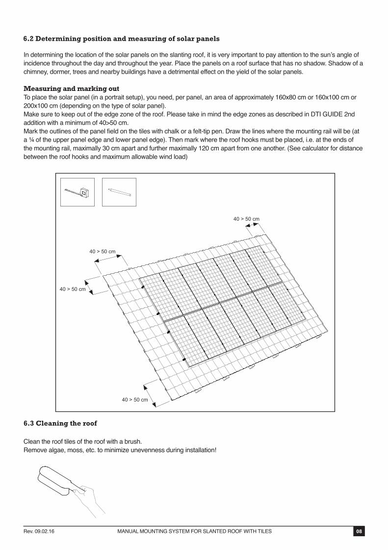
6.2 Determining position and measuring of solar panels
In determining the location of the solar panels on the slanting roof, it is very important to pay attention to the sun’s angle of incidence throughout the day and throughout the year. Place the panels on a roof surface that has no shadow. Shadow of a chimney, dormer, trees and nearby buildings have a detrimental effect on the yield of the solar panels.
Measuring and marking outTo place the solar panel (in a portrait setup), you need, per panel, an area of approximately 160x80 cm or 160x100 cm or 200x100 cm (depending on the type of solar panel).Make sure to keep out of the edge zone of the roof. Please take in mind the edge zones as described in DTI GUIDE 2nd addition with a minimum of 40>50 cm.Mark the outlines of the panel field on the tiles with chalk or a felt-tip pen. Draw the lines where the mounting rail will be (at a ¼ of the upper panel edge and lower panel edge). Then mark where the roof hooks must be placed, i.e. at the ends of the mounting rail, maximally 30 cm apart and further maximally 120 cm apart from one another. (See calculator for distance between the roof hooks and maximum allowable wind load)
08Rev. 09.02.16 MANUAL MOUNTING SYSTEM FOR SLANTED ROOF WITH TILES
6.3 Cleaning the roof
Clean the roof tiles of the roof with a brush.Remove algae, moss, etc. to minimize unevenness during installation!
40 > 50 cm
40 > 50 cm
40 > 50 cm
40 > 50 cm
7. Installation
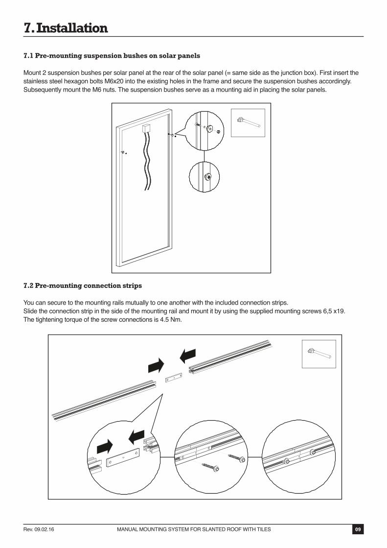
7.1 Pre-mounting suspension bushes on solar panels
Mount 2 suspension bushes per solar panel at the rear of the solar panel (= same side as the junction box). First insert the stainless steel hexagon bolts M6x20 into the existing holes in the frame and secure the suspension bushes accordingly. Subsequently mount the M6 nuts. The suspension bushes serve as a mounting aid in placing the solar panels.
7.2 Pre-mounting connection strips
You can secure to the mounting rails mutually to one another with the included connection strips.Slide the connection strip in the side of the mounting rail and mount it by using the supplied mounting screws 6,5 x19. The tightening torque of the screw connections is 4.5 Nm.
09Rev. 09.02.16 MANUAL MOUNTING SYSTEM FOR SLANTED ROOF WITH TILES

7.3 Securing roof hooks
You determine the position of the roof hooks based on the location of the solar panels on the roof.The roof hooks are attached to ¼ H of the panel top edge and panel bottom edge. Thus, a mutual distance of 2/4 H, this is approximately 3 roof tiles (others depend on the type of roof tile).Divide the roof hooks proportional to the line where the mounting rails will be. The roof hooks may be placed maximally 30-60 cm apart. (See calculator for distance.) Place an additional roof hook at the ends at mutual intervals of approximately 30 cm.
1. Draw with chalk or the felt-tip pen on the place where the hooks must come. Do this on the tile under the roof hook. This tile remains where it is with the mounting of the roof hook.2. Slide the row of tiles above the roof hooks upwards and underneath the top roof tile. Place the roof hook into the cavity (valley) of the underlying roof tile over the roof tile and batten. With some roof tiles the tile must be adjusted to the roof hook with an angle grinder or a file so that the roof tiles close properly again to ensure weather tightness of the roof.3. Slide the row of tiles above the roof hook downwards again.4. Make sure that the roof hooks are mutually aligned.
Optional Roof hook Multi can also be used. Adjust the upper part of the roof hook to the correct width. Adjustment is based on width of the tile and batten. Slide the row of tiles above the roof hooks upwards and underneath the top roof tile. Place the roof hook into the cavity (valley) of the underlying roof tile over the roof tile and batten. With some roof tiles the tile must be adjusted to the roof hook with an angle grinder or a file so that the roof tiles close properly again to ensure weather tightness of the roof.
10Rev. 09.02.16 MANUAL MOUNTING SYSTEM FOR SLANTED ROOF WITH TILES
See Calculator
30 -60 cm
2/4 H
2/4 H2/4 H
1/4 H
1
2
3
4
1/4 H
30-63 mm
OPTION
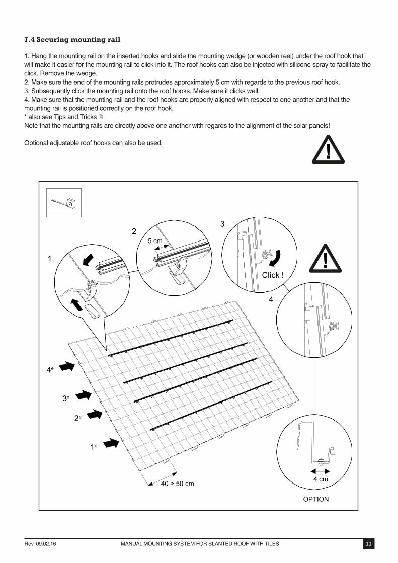
7.4 Securing mounting rail
1. Hang the mounting rail on the inserted hooks and slide the mounting wedge (or wooden reel) under the roof hook that will make it easier for the mounting rail to click into it. The roof hooks can also be injected with silicone spray to facilitate the click. Remove the wedge.2. Make sure the end of the mounting rails protrudes approximately 5 cm with regards to the previous roof hook.3. Subsequently click the mounting rail onto the roof hooks. Make sure it clicks well.4. Make sure that the mounting rail and the roof hooks are properly aligned with respect to one another and that the mounting rail is positioned correctly on the roof hook.* also see Tips and Tricks Note that the mounting rails are directly above one another with regards to the alignment of the solar panels!
Optional adjustable roof hooks can also be used.
11Rev. 09.02.16 MANUAL MOUNTING SYSTEM FOR SLANTED ROOF WITH TILES
1
23
4
Click !
5 cm
40 > 50 cm
4e
3e
2e
1e
4 cm
OPTION

7.5 Hanging solar panels onto mounting rail
Hang the first solar panel by using the pre-mounted suspension bushes temporarily on to the upper mounting rail. As a result, you will have your hands free for the rest of the installation.
12Rev. 09.02.16 MANUAL MOUNTING SYSTEM FOR SLANTED ROOF WITH TILES

7.6 Mounting 1st solar panel on the rails
Slide the first solar panel to the side of the mounting rail.Then slide the end clamp onto the mounting rail. Choose the correct slot so that the end clamp connects to the solar panel. Let approximately 1 cm of the rail protrude visibly next to the end clamp. Fasten the end clamp subsequently with the mounting screw. The tightening torque of the screw connections is 4.5 Nm.Option: Slide the black end caps into the side of the mounting rails and place the colour caps over the mounting screws.
13Rev. 09.02.16 MANUAL MOUNTING SYSTEM FOR SLANTED ROOF WITH TILES
1
2
X Y1 cm
OPTION

7.7 Mounting of other solar panels on the rails
Hang the second solar panel on the mounting rail and slide it towards the first one until a gap remains of approximately 7 mm. Subsequently screw the mounting screw with a module clamping plate into the mounting rail. The tightening torque of the screw connections is 4.5 Nm.Take note that the solar panels are aligned correctly before tightening the screw! Repeat this with the remaining solar panels. Option: Place the black colour caps over the mounting screws.
14Rev. 09.02.16 MANUAL MOUNTING SYSTEM FOR SLANTED ROOF WITH TILES
7 mm
OPTION

7.8 Final mounting / multiple rows underneath one another
1. Slide the end clamp onto the mounting rail. Choose the correct notch so that the end clamp connects to the solar panel.2. Fasten the end clamp with the mounting screw (tightening torque 4.5 Nm).3. To obtain a continuous flat panel, slide the underlying solar panels, after you have hung them with the suspension bushes onto the mounting rail, against the upper row of solar panels with a gap of 1 - 2 cm.Subsequently secure the solar panels firmly onto the mounting rails by means of the mounting screws, end clamps and module clamping plates.Option: Slide the black end caps into the sides of the mounting rails and place the colour caps over the mounting screws.
15Rev. 09.02.16 MANUAL MOUNTING SYSTEM FOR SLANTED ROOF WITH TILES
1 2
3
OPTION
OPTION
OPTION
8. APPENDIX
16Rev. 09.02.16 MANUAL MOUNTING SYSTEM FOR SLANTED ROOF WITH TILES
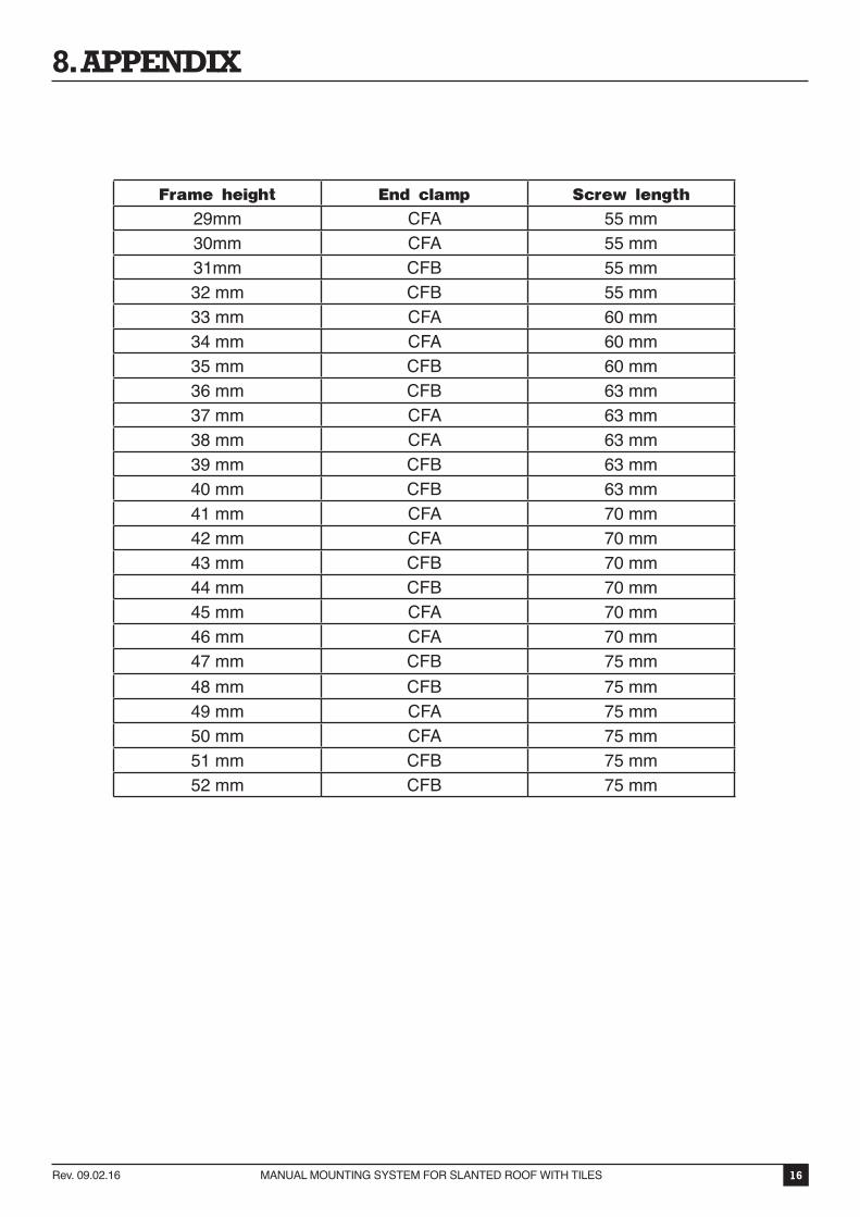
Frame height End clamp Screw length
29mm CFA 55 mm30mm CFA 55 mm31mm CFB 55 mm32 mm CFB 55 mm33 mm CFA 60 mm34 mm CFA 60 mm35 mm CFB 60 mm36 mm CFB 63 mm37 mm CFA 63 mm38 mm CFA 63 mm39 mm CFB 63 mm40 mm CFB 63 mm41 mm CFA 70 mm42 mm CFA 70 mm43 mm CFB 70 mm44 mm CFB 70 mm45 mm CFA 70 mm46 mm CFA 70 mm47 mm CFB 75 mm48 mm CFB 75 mm49 mm CFA 75 mm50 mm CFA 75 mm51 mm CFB 75 mm52 mm CFB 75 mm