Manual Cutler Hammer
114
CA08104001E For more information visit: www.eaton.com January 2008 Contents Power Distribution Systems 1.0-1 i ii 1 2 3 4 5 6 7 8 9 10 11 12 13 14 15 16 17 18 19 20 21 Sheet 01001 Power Distribution Systems Power Distribution Systems System Design Basic Principles . . . . . . . . . . . 1.1-1 Modern Electric Power Technologies . . . . . . . . . . . 1.1-1 Goals of System Design . . . 1.1-2 Voltage Classifications; BILs — Basic Impulse Levels . . . . . 1.1-4 3-Phase Transformer Winding Connections . . . . 1.1-5 Types of Systems — Radial, Loop, Selective, Two-Source, Sparing Transformer, Spot Network, Distribution . . . . 1.1-6 Health Care Facility Design Considerations . . . 1.1-14 Generator Systems . . . . . . 1.1-17 Generator System Design Types of Generators . . . . . . . 1.2-1 Generator Systems . . . . . . . 1.2-2 Generator Grounding. . . . . . 1.2-3 Generator Controls . . . . . . . . 1.2-4 Generator Short Circuit Characteristics . . . . . . . . . . 1.2-4 Generator Protection . . . . . . 1.2-5 System Analysis Systems Analysis . . . . . . . . . 1.3-1 Short Circuit Currents . . . . . 1.3-2 Fault Current Waveform Relationships . . . . . . . . . . . 1.3-3 Fault Current Calculations and Methods Index . . . . . . 1.3-4 Determine X and R from Transformer Loss Data . . . 1.3-19 Voltage Drop Considerations . . . . . . . . . . 1.3-23 System Application Considerations Capacitors/Power Factor. . . 1.4-1 Overcurrent Protection and Coordination . . . . . . . . 1.4-3 Protection of Conductors . . . 1.4-5 Circuit Breaker Cable Temperature Ratings . . . . . 1.4-5 Zone Selective Interlocking . 1.4-5 Ground Fault Protection . . . 1.4-6 Suggested Ground Fault Settings . . . . . . . . . . . . . 1.4-6 Grounding/Ground Fault Protection Grounding — Equipment, System, MV System, LV System . . . . . . . . . . . . . . 1.4-6 Ground Fault Protection . . . . 1.4-11 Lightning and Surge Protection . . . . . . . . . . . . . . 1.4-14 Grounding Electrodes. . . . . . 1.4-14 Power Quality Terms, Technical Overview . . 1.4-15 TVSS . . . . . . . . . . . . . . . . . . . 1.4-16 Harmonics and Nonlinear Loads . . . . . . . . . 1.4-18 UPS . . . . . . . . . . . . . . . . . . . . 1.4-22 Other Application Considerations Secondary Voltage . . . . . . . . 1.4-28 Energy Conservation . . . . . . 1.4-29 Building Control Systems . . 1.4-30 Cogeneration . . . . . . . . . . . . . 1.4-30 Emergency Power . . . . . . . . . 1.4-30 Peak Shaving . . . . . . . . . . . . . 1.4-31 Sound Levels . . . . . . . . . . . . . 1.4-32 Reference Data IEEE Protective Relay Numbers . . . . . . . . . . . . . . . 1.5-1 Codes and Standards . . . . . . 1.5-6 Motor Protective Device Data . . . . . . . . . . . . . 1.5-7 Chart of Short Circuit Currents for Transformers . . 1.5-9 Transformer Full Load Amperes and Impedances . . . . . . . . . 1.5-10 Transformer Losses, TP-1 Losses . . . . . . . . . . . . . 1.5-12 Power Equipment Losses . . . 1.5-13 NEMA Enclosure Definitions. . 1.5-13 Cable R, X, Z Data . . . . . . . . . 1.5-15 Conductor Ampacities . . . . . 1.5-16 Conductor Temperature Ratings . . . . . . . . . . . . . . . . 1.5-16 Formulas and Terms . . . . . . . 1.5-18 Seismic Requirements . . . . . 1.5-19 Designing a Distribution System
-
Upload
marcelo-palacios-santana -
Category
Documents
-
view
621 -
download
17
Transcript of Manual Cutler Hammer
CA08104001E For more information visit:
www.eaton.com
January 2008
Contents
Power Distribution Systems 1.0-1
i
ii
1
2
3
4
5
6
7
8
9
10
11
12
13
14
15
16
17
18
19
20
21
Sheet
01
001
Po
wer
Dis
trib
uti
on
Syste
ms
Power Distribution Systems
System Design
Basic Principles. . . . . . . . . . .
1.1-1
Modern Electric Power Technologies . . . . . . . . . . .
1.1-1
Goals of System Design . . .
1.1-2
Voltage Classifications; BILs — Basic Impulse Levels . . . . .
1.1-4
3-Phase Transformer Winding Connections . . . .
1.1-5
Types of Systems — Radial, Loop, Selective, Two-Source, Sparing Transformer, Spot Network, Distribution . . . .
1.1-6
Health Care Facility Design Considerations . . .
1.1-14
Generator Systems . . . . . .
1.1-17
Generator System Design
Types of Generators . . . . . . .
1.2-1
Generator Systems . . . . . . .
1.2-2
Generator Grounding. . . . . .
1.2-3
Generator Controls. . . . . . . .
1.2-4
Generator Short CircuitCharacteristics . . . . . . . . . .
1.2-4
Generator Protection . . . . . .
1.2-5
System Analysis
Systems Analysis . . . . . . . . .
1.3-1
Short Circuit Currents . . . . .
1.3-2
Fault Current Waveform Relationships . . . . . . . . . . .
1.3-3
Fault Current Calculations and Methods Index . . . . . .
1.3-4
Determine X and R from Transformer Loss Data . . .
1.3-19
Voltage Drop Considerations . . . . . . . . . .
1.3-23
System Application Considerations
Capacitors/Power Factor. . . 1.4-1
Overcurrent Protection and Coordination
. . . . . . . .
1.4-3
Protection of Conductors . . .
1.4-5
Circuit Breaker Cable Temperature Ratings
. . . . .
1.4-5
Zone Selective Interlocking .
1.4-5
Ground Fault Protection . . .
1.4-6
Suggested Ground Fault Settings . . . . . . . . . . . . .
1.4-6
Grounding/Ground Fault Protection
Grounding — Equipment, System, MV System, LV System . . . . . . . . . . . . . .
1.4-6
Ground Fault Protection . . . .
1.4-11
Lightning and Surge Protection . . . . . . . . . . . . . .
1.4-14
Grounding Electrodes. . . . . .
1.4-14
Power Quality
Terms, Technical Overview . .
1.4-15
TVSS . . . . . . . . . . . . . . . . . . .
1.4-16
Harmonics and Nonlinear Loads . . . . . . . . .
1.4-18
UPS . . . . . . . . . . . . . . . . . . . .
1.4-22
Other Application Considerations
Secondary Voltage . . . . . . . .
1.4-28
Energy Conservation . . . . . .
1.4-29
Building Control Systems . .
1.4-30
Cogeneration. . . . . . . . . . . . .
1.4-30
Emergency Power. . . . . . . . .
1.4-30
Peak Shaving. . . . . . . . . . . . .
1.4-31
Sound Levels. . . . . . . . . . . . .
1.4-32
Reference Data
IEEE Protective Relay Numbers . . . . . . . . . . . . . . .
1.5-1
Codes and Standards . . . . . .
1.5-6
Motor Protective Device Data . . . . . . . . . . . . .
1.5-7
Chart of Short Circuit Currents for Transformers . .
1.5-9
Transformer Full Load Amperes and Impedances . . . . . . . . .
1.5-10
Transformer Losses, TP-1 Losses . . . . . . . . . . . . .
1.5-12
Power Equipment Losses . . .
1.5-13
NEMA Enclosure Definitions
. .
1.5-13
Cable R, X, Z Data . . . . . . . . .
1.5-15
Conductor Ampacities . . . . .
1.5-16
Conductor Temperature Ratings . . . . . . . . . . . . . . . .
1.5-16
Formulas and Terms. . . . . . .
1.5-18
Seismic Requirements . . . . .
1.5-19
Designing a Distribution System
1.0-2
For more information visit:
www.eaton.com
CA08104001E
January 2008
Power Distribution Systems
i
ii
1
2
3
4
5
6
7
8
9
10
11
12
13
14
15
16
17
18
19
20
21
Sheet
01
002
This page intentionally left blank.
CA08104001E For more information visit:
www.eaton.com
1.1-1
January 2008
Power Distribution Systems
i
ii
1
2
3
4
5
6
7
8
9
10
11
12
13
14
15
16
17
18
19
20
21
Sheet
01
System Design
003
Basic Principles
The best distribution system is one that will, cost effectively and safely, supply adequate electric service to both present and future probable loads — this section is included to aid in selecting, designing and installing such a system.
The function of the electric power distribution system in a building or installation site is to receive power at one or more supply points and deliver it to the individual lamps, motors, and all other electrically operated devices. The importance of the distribution system to the function of a building makes it almost imperative that the best system be designed and installed.
In order to design the best distribution system, the system design engineer must have information concerning the loads and a knowledge of the various types of distribution systems that are applicable. The various categories of buildings have many specific design challenges, but certain basic principles are common to all. Such principles, if followed, will provide a soundly executed design.
The basic principles or factors requir-ing consideration during design of the power distribution system include:
■
Functions of structure, present and future.
■
Life and flexibility of structure.
■
Locations of service entrance and distribution equipment, locations and characteristics of loads, locations of unit substations.
■
Demand and diversity factors of loads.
■
Sources of power; including normal, standby and emergency (see
Section 42
).
■
Continuity and quality of power available and required (see
Section 41
).
■
Energy efficiency and management.
■
Distribution and utilization voltages.
■
Bus and/or cable feeders.
■
Distribution equipment and motor control.
■
Power and lighting panelboards and motor control centers.
■
Types of lighting systems.
■
Installation methods.
■
Power monitoring systems.
■
Electric utility requirements.
Modern Electric Power Technologies
Several new factors to consider in modern power distribution systems result from two relatively recent changes. The first recent change is utility deregulation. The traditional dependence on the utility for problem analysis; energy conservation mea-surements and techniques; and a simplified cost structure for electricity has changed. The second change is less obvious to the designer yet will have an impact on the types of equipment and systems being designed. It is the diminishing quantity of qualified build-ing electrical operators; maintenance departments; and facility engineers.
Modern electric power technologies may be of use to the designer and building owner in addressing these new challenges. The advent of micro-processor devices (smart devices) into power distribution equipment has expanded facility owners’ options and capabilities, allowing for automated communication of vital power system information (both energy data and system operation information) and electrical equipment control.
These technologies may be grouped as:
■
Power monitoring and control.
■
Building management systems interfaces.
■
Lighting control.
■
Automated energy management.
■
Predictive diagnostics.
Various sections of this guide cover the application and selection of such systems and components that may be incorporated into the power equip-ment being designed. See
Sections 2, 3, 4, 23
and
43
.
1.1-2
For more information visit:
www.eaton.com
CA08104001E
January 2008
Power Distribution Systems
i
ii
1
2
3
4
5
6
7
8
9
10
11
12
13
14
15
16
17
18
19
20
21
Sheet
01
System Design
004
Goals of System Design
When considering the design of an electrical distribution system for a given customer and facility, the electri-cal engineer must consider alternate design approaches which best fit the following overall goals.
1. Safety
: The No. 1 goal is to design a power system which will not present any electrical hazard to the people who utilize the facility, and/or the utilization equipment fed from the electrical system. It is also important to design a system which is inherently safe for the people who are responsi-ble for electrical equipment maintenance and upkeep.
The National Electrical Code
�
(NEC), NFPA 70 and NFPA 70E, as well as local electrical codes provide minimum standards and requirements in the area of wiring design and protection, wiring methods and materials as well as equipment for general use with the overall goal of providing safe electrical distribution systems and equipment.
The NEC also covers
minimum
requirements for special occupan-cies including hazardous locations and special use type facilities such as health care facilities, places of assembly, theaters, etc. and the equipment and systems located in these facilities. Special equipment and special conditions such as emergency systems, standby systems and communication sys-tems are also covered in the code.
It is the responsibility of the design engineer to be familiar with the NFPA and NEC code requirements as well as the customer’s facility, process, and operating procedures; to design a system which protects personnel from electrical live conductors and utilizes adequate circuit protective devices which will selectively isolate overloaded or faulted circuits or equipment as quickly as possible.
2. Minimum Initial Investment
: The owner’s overall budget for first cost purchase and installa-tion of the electrical distribution system and electrical utilization equipment will be a key factor in determining which of various alternate system designs are to be selected. When trying to minimize initial investment for electrical equipment, consideration should be given to the cost of installation, floor space requirements and pos-sible extra cooling requirements as well as the initial purchase price.
3. Maximum Service Continuity
: The degree of service continuity and reliability needed will vary depending on the type and use of the facility as well as the loads or processes being supplied by the electrical distribution system. For example, for a smaller com-mercial office building a power outage of considerable time, say several hours, may be acceptable, whereas in a larger commercial building or industrial plant only a few minutes may be acceptable. In other facilities such as hospitals, many critical loads permit a maxi-mum of 10 seconds outage and certain loads, such as real-time computers, cannot tolerate a loss of power for even a few cycles.
Typically, service continuity and reliability can be increased by:
A. Supplying multiple utility power sources or services.
B. Supplying multiple connection paths to the loads served.
C. Using short-time rated power circuit breakers.
D. Providing alternate customer-owned power sources such as generators or batteries supplying uninterruptable power supplies.
E. Selecting the highest quality elec-trical equipment and conductors.
F. Using the best installation methods.
G. Designing appropriate system alarms, monitoring and diagnostics.
H. Selecting preventative mainte-nance systems or equipment to alarm before an outage occurs.
4. Maximum Flexibility and Expendability
: In many industrial manufacturing plants, electrical utilization loads are periodically relocated or changed requiring changes in the electrical distribu-tion system. Consideration of the layout and design of the electrical distribution system to accommo-date these changes must be con-sidered. For example, providing many smaller transformers or loadcenters associated with a given area or specific groups of machinery may lend more flexibility for future changes than one large transformer; the use of plug-in busways to feed selected equip-ment in lieu of conduit and wire may facilitate future revised equipment layouts.
In addition, consideration must be given to future building expansion, and/or increased load require-ments due to added utilization equipment when designing the electrical distribution system. In many cases considering trans-formers with increased capacity or fan cooling to serve unexpected loads as well as including spare additional protective devices and/or provision for future addition of these devices may be desirable. Also to be considered is increasing appropriate circuit capacities or quantities for future growth.
Power monitoring communication systems connected to electronic metering can provide the trending and historical data necessary for future capacity growth.
CA08104001E For more information visit:
www.eaton.com
1.1-3
January 2008
Power Distribution Systems
i
ii
1
2
3
4
5
6
7
8
9
10
11
12
13
14
15
16
17
18
19
20
21
Sheet
01
System Design
005
5. Maximum Electrical Efficiency (Minimum Operating Costs)
: Electrical efficiency can generally be maximized by designing sys-tems that minimize the losses in conductors, transformers and utili-zation equipment. Proper voltage level selection plays a key factor in this area and will be discussed later. Selecting equipment, such as transformers, with lower operating losses, generally means higher first cost and increased floor space requirements; thus, there is a balance to be considered between the owner’s utility energy change for the losses in the trans-former or other equipment versus the owner’s first cost budget and cost of money.
6. Minimum Maintenance Cost
: Usually the simpler the electrical system design and the simpler the electrical equipment, the less the associated maintenance costs and operator errors. As electrical systems and equipment become more complicated to provide greater service continuity or flexibility, the maintenance costs and chance for operator error increases. The systems should be designed with an alternate power circuit to take electrical equipment (requiring periodic maintenance) out of service without dropping essential loads. Use of drawout type protective devices such as breakers and combination starters can also minimize maintenance cost and out-of-service time.
7. Maximum Power Quality
: The power input requirements of all utilization equipment has to be considered including the accept-able operating range of the equip-ment and the electrical distribution system has to be designed to meet these needs. For example, what is the required input voltage, cur-rent, power factor requirement? Consideration to whether the loads are affected by harmonics (multiples of the basic 60 cycle per second sine wave) or generate harmonics must be taken into account as well as transient voltage phenomena.
The above goals are interrelated and in some ways contradictory. As more redundancy is added to the electrical system design along with the best quality equipment to maximize service continuity, flexibility and expandability, and power quality, the more initial investment and maintenance are increased. Thus, the designer must weigh each factor based on the type of facility, the loads to be served, the owner’s past experience and criteria.
Summary
It is to be expected that the engineer will never have complete load infor-mation available when the system is designed. The engineer will have to expand the information made avail-able to him on the basis of experience with similar problems. Of course, it is desirable that the engineer has as much definite information as possible concerning the function, requirements, and characteristics of the utilization devices. The engineer should know whether certain loads function separately or together as a unit, the magnitude of the demand of the loads
viewed separately and as units, the rated
voltage and frequency of the devices, their physical location with respect to each other and with respect to the source and the probability and possi-bility of the relocation of load devices and addition of loads in the future.
Coupled with this information, a knowledge of the major types of electric power distribution systems equips the engineers to arrive at the best system design for the particular building.
It is beyond the scope of this guide to present a detailed discussion of loads that might be found in each of several types of buildings. Assuming that the design engineer has assembled the necessary load data, the following pages discuss some of the various types of electrical distribution systems that can be utilized. The description of types of systems, and the diagrams used to explain the types of systems on the following pages omits the location of utility revenue metering equipment for clarity. A discussion of short circuit calculations, coordination, voltage selection, voltage drop, ground fault protection, motor protection, and other specific equipment protection is also presented.
1.1-4
For more information visit:
www.eaton.com
CA08104001E
January 2008
Power Distribution Systems
i
ii
1
2
3
4
5
6
7
8
9
10
11
12
13
14
15
16
17
18
19
20
21
Sheet
01
System Design
006
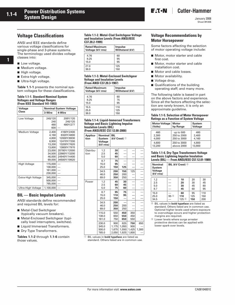
Voltage ClassificationsANSI and IEEE standards define various voltage classifications for single-phase and 3-phase systems. The terminology used divides voltage classes into:
■ Low voltage.■ Medium voltage.■ High voltage.■ Extra-high voltage.■ Ultra-high voltage.
Table 1.1-1 presents the nominal sys-tem voltages for these classifications.
Table 1.1-1. Standard Nominal System Voltages and Voltage Ranges (From IEEE Standard 141-1993)
BIL — Basic Impulse LevelsANSI standards define recommended and required BIL levels for:
■ Metal-Clad Switchgear (typically vacuum breakers).
■ Metal-Enclosed Switchgear (typi-cally load interrupters, switches).
■ Liquid Immersed Transformers.■ Dry-Type Transformers.
Tables 1.1-2 through 1.1-6 contain those values.
Voltage Class
Nominal System Voltage
3-Wire 4-Wire
Low Voltage 240/120240480600
208Y/120240/120
480Y/277—
Medium Voltage 2,4004,1604,8006,900
13,20013,80023,00034,50046,00069,000
4160Y/24008320Y/4800
12000Y/693012470Y/720013200Y/762013800Y/7970
20780Y/1200022860Y/1320024940Y/1440034500Y/19920
High Voltage 115,000138,000161,000230,000
————
Extra-High Voltage 345,000500,000765,000
———
Ultra-High Voltage 1,100,000 —
Table 1.1-2. Metal-Clad Switchgear Voltage and Insulation Levels (From ANSI/IEEE C37.20.2-1999)
Table 1.1-3. Metal-Enclosed SwitchgearVoltage and Insulation Levels (From ANSI C37.20.3-1987)
Table 1.1-4. Liquid-Immersed TransformersVoltage and Basic Lightning Impulse Insulation Levels (BIL) (From ANSI/IEEE C57.12.00-2000)
� BIL values in bold typeface are listed as standard. Others listed are in common use.
Voltage Recommendations by Motor HorsepowerSome factors affecting the selection of motor operating voltage include:
■ Motor, motor starter and cable first cost.
■ Motor, motor starter and cable installation cost.
■ Motor and cable losses.■ Motor availability.■ Voltage drop.■ Qualifications of the building
operating staff; and many more.
The following table is based in part on the above factors and experience. Since all the factors affecting the selec-tion are rarely known, it is only an approximate guideline.
Table 1.1-5. Selection of Motor Horsepower Ratings as a Function of System Voltage
Table 1.1-6. Dry-Type Transformers Voltage and Basic Lightning Impulse Insulation Levels (BIL) — From ANSI/IEEE C57.12.01-1989)
� BIL values in bold typeface are listed as standard. Others listed are in common use. Optional higher levels used where exposure to overvoltage occurs and higher protection margins are required.
� Lower levels where surge arrester protective devices can be applied with lower spark-over levels.
Rated Maximum Voltage (kV rms)
Impulse Withstand (kV)
4.76 8.2515.0
60 95 95
27.038.0
125150
Rated Maximum Voltage (kV rms)
Impulse Withstand (kV)
4.76 8.2515.0
60 75 95
15.525.838.0
110125150
Applica-tion
Nominal SystemVoltage (kV rms)
BIL (kV Crest) �
Distribu-tion
1.2 2.5 5.0
304560
———
———
———
8.7 15.0 25.0
7595
150
——
125
———
———
34.5 46.0 69.0
200250350
150200250
125——
———
Power 1.2 2.5 5.0
456075
304560
———
———
8.7 15.0 25.0
95110150
7595—
———
———
34.5 46.0 69.0
200250350
—200250
———
———
115.0138.0161.0
550650750
450550650
350450550
———
230.0345.0500.0765.0
9001,1751,6752,050
8251,0501,5501,925
750900
1,4251,800
650—
1,300—
Motor Voltage (Volts)
Motor hp Range
System Voltage
460 2,300 4,000
up to 500250 to 2000 250 to 3000
480 2,400 4,160
4,60013,200
250 to 3000 above 2000
4,80013,800
NominalSystemVoltage(kV rms)
BIL (kV Crest) �
1.2 2.5 5.0 8.7
————
10 20 30 45
20 30 45 60
30 45 60 95
15.025.034.5
—95 �—
60110125 �
95125150
110150200

CA08104001E For more information visit: www.eaton.com
1.1-5January 2008
Power Distribution Systems
i
ii
1
2
3
4
5
6
7
8
9
10
11
12
13
14
15
16
17
18
19
20
21
Sheet 01
System Design007
Table 1.1-7. 3-Phase Transformer Winding ConnectionsPhasor Diagram
Notes
1. Suitable for both ungrounded and effectively grounded sources.2. Suitable for a 3-wire service or a 4-wire service with a mid-tap ground.
1. Suitable for both ungrounded and effectively grounded sources.2. Suitable for a 3-wire service or a 4-wire grounded service with XO grounded.3. With XO grounded, the transformer acts as a ground source for the
secondary system.4. Fundamental and harmonic frequency zero-sequence currents in the secondary
lines supplied by the transformer do not flow in the primary lines. Instead the zero sequence currents circulate in the closed delta primary windings.
5. When supplied from an effectively grounded primary system does not see loadunbalances and ground faults in the secondary system.
1. Suitable for both ungrounded and effectively grounded sources.2. Suitable for a 3-wire service or a 4-wire delta service with a mid-tap ground.3. Grounding the primary neutral of this connection would create a ground source
for the primary system. This could subject the transformer to severe overloadingduring a primary system disturbance or load unbalance.
4. Frequently installed with mid-tap ground on one leg when supplying combination 3-phase and single-phase load where the 3-phase load is much larger than single-phase load.
5. When used in 25 kV and 35 kV 3-phase 4-wire primary systems, ferroresonance can occur when energizing or de-energizing the transformer using single-pole switches located at the primary terminals. With smaller kVA transformers the probability of ferroresonance is higher.
1. Suitable for both ungrounded and effectively grounded sources.2. Suitable for a 3-wire service only, even if XO is grounded.3. This connection is incapable of furnishing a stabilized neutral and its use may
result in phase-to-neutral overvoltage (neutral shift) as a result of unbalanced phase-to-neutral load.
4. If a 3-phase unit is built on a three-legged core, the neutral point of the primary windings is practically locked at ground potential.
1. Suitable for 4-wire effectively grounded source only.2. Suitable for a 3-wire service or for 4-wire grounded service with XO grounded.3. 3-phase transformers with this connection may experience stray flux tank
heating during certain external system unbalances unless the core configuration (four or five legged) utilized provides a return path for the flux.
4. Fundamental and harmonic frequency zero-sequence currents in the secondary lines supplied by the transformer also flow in the primary lines (and primary neutral conductor).
5. Ground relay for the primary system may see load unbalances and ground faults in the secondary system. This must be considered when coordinating overcurrent protective devices.
6. 3-phase transformers with the neutral points of the high voltage and low voltage windings connected together internally and brought out through an HOXO bushing should not be operated with the HOXO bushing ungrounded (floating). To do so can result in very high voltages in the secondary systems.
1. Suitable for both ungrounded and effectively grounded sources.2. Suitable for a 3-wire service or a 4-wire service with a mid-tap ground.3. When using the tap for single-phase circuits the single-phase load kVA should
not exceed 5% of the 3-phase kVA rating of the transformer. The 3-phase rating of the transformer is also substantially reduced.
H2
H1 H3
X2
X1 X3
DELTA-DELTA Connection
PhasorDiagram:
Angular Displacement (Degrees): 0
H2
H1 H3
X2
X1
X3
DELTA-WYE Connection
PhasorDiagram:
Angular Displacement (Degrees): 30
X0
H2
H1 H3
X2
X1
X3
WYE-DELTA Connection
PhasorDiagram:
Angular Displacement (Degrees): 30
H2
H1 H3
WYE-WYE Connection
PhasorDiagram:
Angular Displacement (Degrees): 0
X2
X1 X3
X0
H2
H1 H3
GROUNDED WYE-WYE Connection
PhasorDiagram:
Angular Displacement (Degrees): 0
X2
X1 X3
X0H0
H2
H1 H3
X2
X1 X3
DELTA-DELTA Connection with Tap
PhasorDiagram:
Angular Displacement (Degrees): 0
X4
1.1-6
For more information visit: www.eaton.com CA08104001E
January 2008
Power Distribution Systems
i
ii
1
2
3
4
5
6
7
8
9
10
11
12
13
14
15
16
17
18
19
20
21
Sheet 01
System Design008
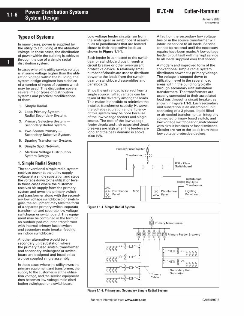
Types of SystemsIn many cases, power is supplied by the utility to a building at the utilization voltage. In these cases, the distribution of power within the building is achieved through the use of a simple radial distribution system.
In cases where the utility service voltage is at some voltage higher than the utili-zation voltage within the building, the system design engineer has a choice of a number of types of systems which may be used. This discussion covers several major types of distribution systems and practical modifications of them.
1. Simple Radial.
2. Loop-Primary System — Radial Secondary System.
3. Primary Selective System — Secondary Radial System.
4. Two-Source Primary — Secondary Selective System.
5. Sparing Transformer System.
6. Simple Spot Network.
7. Medium Voltage Distribution System Design.
1. Simple Radial SystemThe conventional simple radial system receives power at the utility supply voltage at a single substation and steps the voltage down to the utilization level. In those cases where the customer receives his supply from the primary system and owns the primary switch and transformer along with the second-ary low voltage switchboard or switch-gear, the equipment may take the form of a separate primary switch, separate transformer, and separate low voltage switchgear or switchboard. This equip-ment may be combined in the form of an outdoor pad-mounted transformer with internal primary fused switch and secondary main breaker feeding an indoor switchboard.
Another alternative would be a secondary unit substation where the primary fused switch, transformer and secondary switchgear or switch-board are designed and installed as a close coupled single assembly.
In those cases where the utility owns the primary equipment and transformer, the supply to the customer is at the utiliza-tion voltage, and the service equipment then becomes low voltage main distri-bution switchgear or a switchboard.
Low voltage feeder circuits run from the switchgear or switchboard assem-blies to panelboards that are located closer to their respective loads as shown in Figure 1.1-1.
Each feeder is connected to the switch-gear or switchboard bus through a circuit breaker or other overcurrent protective device. A relatively small number of circuits are used to distribute power to the loads from the switch-gear or switchboard assemblies and panelboards.
Since the entire load is served from a single source, full advantage can be taken of the diversity among the loads. This makes it possible to minimize the installed transformer capacity. However, the voltage regulation and efficiency of this system may be poor because of the low voltage feeders and single source. The cost of the low voltage-feeder circuits and their associated circuit breakers are high when the feeders are long and the peak demand is above 1000 kVA.
A fault on the secondary low voltage bus or in the source transformer will interrupt service to all loads. Service cannot be restored until the necessary repairs have been made. A low voltage feeder circuit fault will interrupt service to all loads supplied over that feeder.
A modern and improved form of the conventional simple radial system distributes power at a primary voltage. The voltage is stepped down to utilization level in the several load areas within the building typically through secondary unit substation transformers. The transformers are usually connected to their associated load bus through a circuit breaker, as shown in Figure 1.1-2. Each secondary unit substation is an assembled unit consisting of a 3-phase, liquid-filled or air-cooled transformer, an integrally connected primary fused switch, and low voltage switchgear or switchboard with circuit breakers or fused switches. Circuits are run to the loads from these low voltage protective devices.
Figure 1.1-1. Simple Radial System
Figure 1.1-2. Primary and Secondary Simple Radial System
Primary Fused Switch
Transformer
600 V ClassSwitchboard
DistributionDry-TypeTransformer
LightingPanelboard
DistributionPanel
MCC DistributionPanel
Secondary UnitSubstation
Primary Main Breaker
Primary Feeder Breakers
PrimaryCables
52
52 52 52 52 52 52
CA08104001E For more information visit: www.eaton.com
1.1-7January 2008
Power Distribution Systems
i
ii
1
2
3
4
5
6
7
8
9
10
11
12
13
14
15
16
17
18
19
20
21
Sheet 01
System Design009
Since each transformer is located within a specific load area, it must have sufficient capacity to carry the peak load of that area. Consequently, if any diversity exists among the load area, this modified primary radial system requires more transformer capacity than the basic form of the simple radial system. However, because power is distributed to the load areas at a primary voltage, losses are reduced, voltage regulation is improved, feeder circuit costs are reduced substantially, and large low voltage feeder circuit breakers are eliminated. In many cases the inter-rupting duty imposed on the load circuit breakers is reduced.
This modern form of the simple radial system will usually be lower in initial investment than most other types of primary distribution systems for build-ings in which the peak load is above 1000 kVA. A fault on a primary feeder circuit or in one transformer will cause an outage to only those secondary loads served by that feeder or trans-former. In the case of a primary main bus fault or a utility service outage, service is interrupted to all loads until the trouble is eliminated.
Reducing the number of transformers per primary feeder by adding more primary feeder circuits will improve the flexibility and service continuity of this system; the ultimate being one secondary unit substation per primary feeder circuit. This of course increases the investment in the system but minimizes the extent of an outage resulting from a transformer or primary feeder fault.
Primary connections from one second-ary unit substation to the next second-ary unit substation can be made with “double” lugs on the unit substation primary switch as shown, or with sep-arable connectors made in manholes or other locations.
Depending on the load kVA connected to each primary circuit and if no ground fault protection is desired for either the primary feeder conductors and trans-formers connected to that feeder or the main bus, the primary main and/or feeder breakers may be changed to primary fused switches. This will sig-nificantly reduce the first cost, but also decrease the level of conductor and equipment protection. Thus, should a fault or overload condition occur, downtime increases significantly and higher costs associated with increased damage levels and the need for fuse replacement is typically encountered.
In addition, if only one primary fuse on a circuit opens, the secondary loads are then single phased, causing damage to low voltage motors.
Another approach to reducing costs is to eliminate the primary feeder breakers completely, and utilize a single primary main breaker or fused switch for protection of a single pri-mary feeder circuit with all secondary unit sub-stations supplied from this circuit. Although this system results in less initial equipment cost, system reliability is reduced drastically since a single fault in any part of the primary conductor would cause an outage to all loads within the facility.
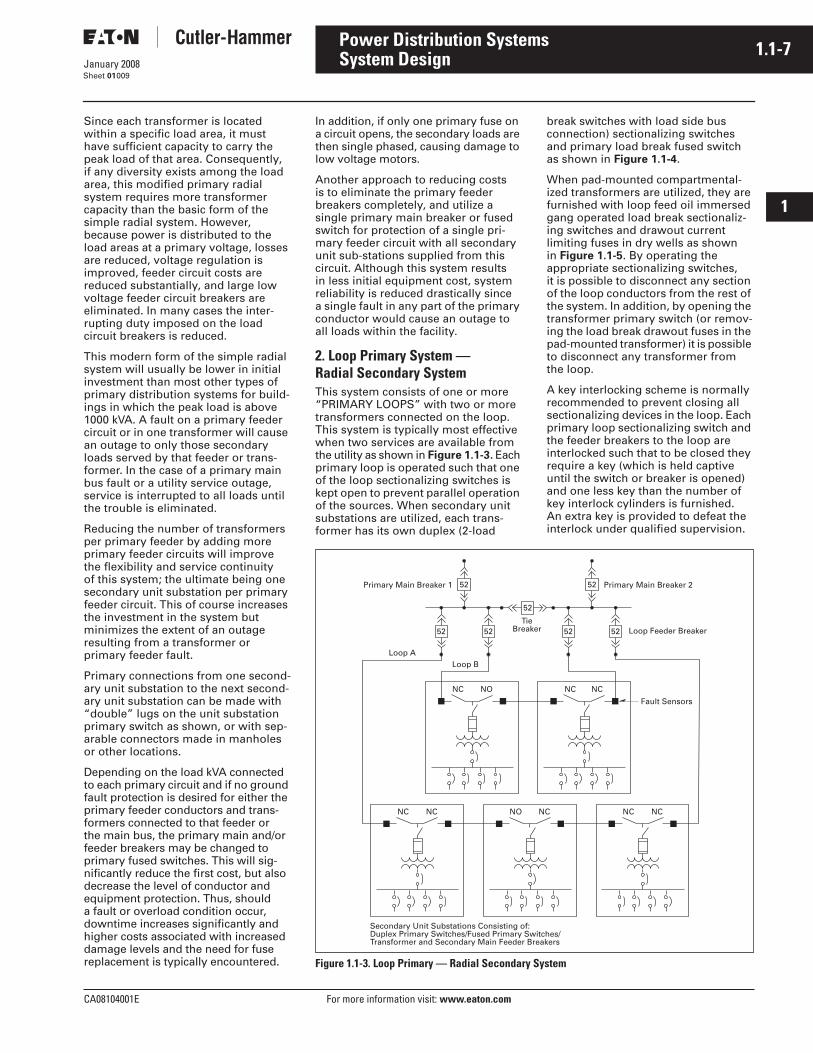
2. Loop Primary System — Radial Secondary SystemThis system consists of one or more “PRIMARY LOOPS” with two or more transformers connected on the loop. This system is typically most effective when two services are available from the utility as shown in Figure 1.1-3. Each primary loop is operated such that one of the loop sectionalizing switches is kept open to prevent parallel operation of the sources. When secondary unit substations are utilized, each trans-former has its own duplex (2-load
break switches with load side bus connection) sectionalizing switches and primary load break fused switch as shown in Figure 1.1-4.
When pad-mounted compartmental-ized transformers are utilized, they are furnished with loop feed oil immersed gang operated load break sectionaliz-ing switches and drawout current limiting fuses in dry wells as shown in Figure 1.1-5. By operating the appropriate sectionalizing switches, it is possible to disconnect any section of the loop conductors from the rest of the system. In addition, by opening the transformer primary switch (or remov-ing the load break drawout fuses in the pad-mounted transformer) it is possible to disconnect any transformer from the loop.
A key interlocking scheme is normally recommended to prevent closing all sectionalizing devices in the loop. Each primary loop sectionalizing switch and the feeder breakers to the loop are interlocked such that to be closed they require a key (which is held captive until the switch or breaker is opened) and one less key than the number of key interlock cylinders is furnished. An extra key is provided to defeat the interlock under qualified supervision.
Figure 1.1-3. Loop Primary — Radial Secondary System
NC NCNO
Loop ALoop B
TieBreaker Loop Feeder Breaker
Primary Main Breaker 2
Secondary Unit Substations Consisting of:Duplex Primary Switches/Fused Primary Switches/Transformer and Secondary Main Feeder Breakers
NO NC NC NCNC NC
NC
52 52
52
5252
52 52
Fault Sensors
Primary Main Breaker 1
1.1-8
For more information visit: www.eaton.com CA08104001E
January 2008
Power Distribution Systems
i
ii
1
2
3
4
5
6
7
8
9
10
11
12
13
14
15
16
17
18
19
20
21
Sheet 01
System Design010
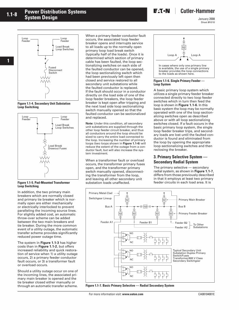
Figure 1.1-4. Secondary Unit Substation Loop Switching
Figure 1.1-5. Pad-Mounted Transformer Loop Switching
In addition, the two primary main breakers which are normally closed and primary tie breaker which is nor-mally open are either mechanically or electrically interlocked to prevent paralleling the incoming source lines. For slightly added cost, an automatic throw-over scheme can be added between the two main breakers and tie breaker. During the more common event of a utility outage, the automatic transfer scheme provides significantly reduced power outage time.
The system in Figure 1.1-3 has higher costs than in Figure 1.1-2, but offers increased reliability and quick restora-tion of service when 1) a utility outage occurs, 2) a primary feeder conductor fault occurs, or 3) a transformer fault or overload occurs.
Should a utility outage occur on one of the incoming lines, the associated pri-mary main breaker is opened and the tie breaker closed either manually or through an automatic transfer scheme.
LoopFeeder
LoopFeeder
Load BreakLoop Switches
FusedDisconnectSwitch
LoopFeeder
LoopFeeder
Load BreakLoop Switches
Load BreakDrawout Fuses
When a primary feeder conductor fault occurs, the associated loop feeder breaker opens and interrupts service to all loads up to the normally open primary loop load break switch (typically half of the loads). Once it is determined which section of primary cable has been faulted, the loop sec-tionalizing switches on each side of the faulted conductor can be opened, the loop sectionalizing switch which had been previously left open then closed and service restored to all secondary unit substations while the faulted conductor is replaced. If the fault should occur in a conductor directly on the load side of one of the loop feeder breakers, the loop feeder breaker is kept open after tripping and the next load side loop sectionalizing switch manually opened so that the faulted conductor can be sectionalized and replaced.
Note: Under this condition, all secondary unit substations are supplied through the other loop feeder circuit breaker, and thus all conductors around the loop should be sized to carry the entire load connected to the loop. Increasing the number of primary loops (two loops shown in Figure 1.1-6) will reduce the extent of the outage from a con-ductor fault, but will also increase the sys-tem investment.
When a transformer fault or overload occurs, the transformer primary fuses open, and the transformer primary switch manually opened, disconnect-ing the transformer from the loop, and leaving all other secondary unit substation loads unaffected.
Figure 1.1-6. Single Primary Feeder — Loop System
A basic primary loop system which utilizes a single primary feeder breaker connected directly to two loop feeder switches which in turn then feed the loop is shown in Figure 1.1-6. In this basic system the loop may be normally operated with one of the loop section-alizing switches open as described above or with all loop sectionalizing switches closed. If a fault occurs in the basic primary loop system, the single loop feeder breaker trips, and second-ary loads are lost until the faulted con-ductor is found and eliminated from the loop by opening the appropriate loop sectionalizing switches and then reclosing the breaker.
3. Primary Selective System — Secondary Radial SystemThe primary selective — secondary radial system, as shown in Figure 1.1-7, differs from those previously described in that it employs at least two primary feeder circuits in each load area. It is
Figure 1.1-7. Basic Primary Selective — Radial Secondary System
Loop A Loop A
In cases where only one primary lineis available, the use of a single primarybreaker provides the loop connectionsto the loads as shown here.
52
Primary Metal-Clad
Switchgear Lineup
Bus A Bus B
Feeder A1 Feeder B1
Primary Feeder Breaker
Feeder B2
Feeder A2
Primary Main Breaker
To OtherSubstations
Typical Secondary UnitSubstation Duplex PrimarySwitch/FusesTransformer/600 V ClassSecondary Switchgear
52 52
52
5252
52 52
NO
NC
NO
NC
NO
NC
CA08104001E For more information visit: www.eaton.com
1.1-9January 2008
Power Distribution Systems
i
ii
1
2
3
4
5
6
7
8
9
10
11
12
13
14
15
16
17
18
19
20
21
Sheet 01
System Design011
designed so that when one primary circuit is out of service, the remaining feeder or feeders have sufficient capacity to carry the total load. Half of the transformers are normally connected to each of the two feeders. When a fault occurs on one of the primary feeders, only half of the load in the building is dropped.
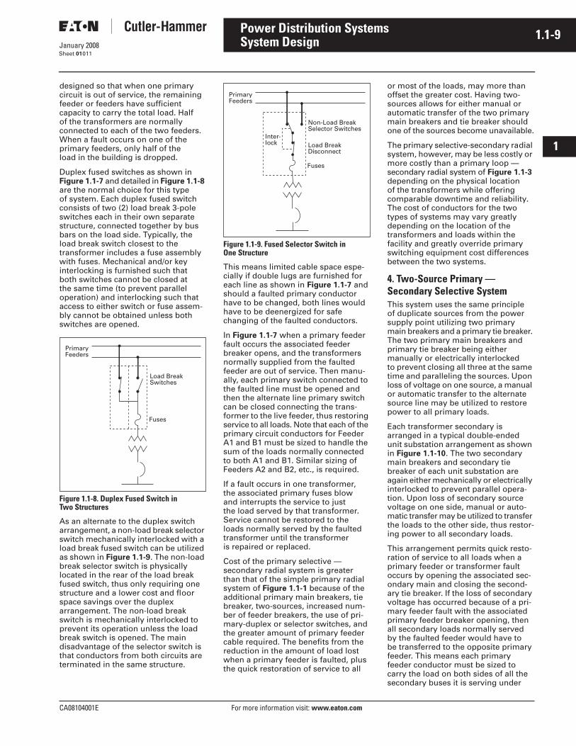
Duplex fused switches as shown in Figure 1.1-7 and detailed in Figure 1.1-8 are the normal choice for this type of system. Each duplex fused switch consists of two (2) load break 3-pole switches each in their own separate structure, connected together by bus bars on the load side. Typically, the load break switch closest to the transformer includes a fuse assembly with fuses. Mechanical and/or key interlocking is furnished such that both switches cannot be closed at the same time (to prevent parallel operation) and interlocking such that access to either switch or fuse assem-bly cannot be obtained unless both switches are opened.
Figure 1.1-8. Duplex Fused Switch in Two Structures
As an alternate to the duplex switch arrangement, a non-load break selector switch mechanically interlocked with a load break fused switch can be utilized as shown in Figure 1.1-9. The non-load break selector switch is physically located in the rear of the load break fused switch, thus only requiring one structure and a lower cost and floor space savings over the duplex arrangement. The non-load break switch is mechanically interlocked to prevent its operation unless the load break switch is opened. The main disadvantage of the selector switch is that conductors from both circuits are terminated in the same structure.
Figure 1.1-9. Fused Selector Switch in One Structure
This means limited cable space espe-cially if double lugs are furnished for each line as shown in Figure 1.1-7 and should a faulted primary conductor have to be changed, both lines would have to be deenergized for safe changing of the faulted conductors.
In Figure 1.1-7 when a primary feeder fault occurs the associated feeder breaker opens, and the transformers normally supplied from the faulted feeder are out of service. Then manu-ally, each primary switch connected to the faulted line must be opened and then the alternate line primary switch can be closed connecting the trans-former to the live feeder, thus restoring service to all loads. Note that each of the primary circuit conductors for Feeder A1 and B1 must be sized to handle the sum of the loads normally connected to both A1 and B1. Similar sizing of Feeders A2 and B2, etc., is required.
If a fault occurs in one transformer, the associated primary fuses blow and interrupts the service to just the load served by that transformer. Service cannot be restored to the loads normally served by the faulted transformer until the transformer is repaired or replaced.
Cost of the primary selective — secondary radial system is greater than that of the simple primary radial system of Figure 1.1-1 because of the additional primary main breakers, tie breaker, two-sources, increased num-ber of feeder breakers, the use of pri-mary-duplex or selector switches, and the greater amount of primary feeder cable required. The benefits from the reduction in the amount of load lost when a primary feeder is faulted, plus the quick restoration of service to all
or most of the loads, may more than offset the greater cost. Having two-sources allows for either manual or automatic transfer of the two primary main breakers and tie breaker should one of the sources become unavailable.
The primary selective-secondary radial system, however, may be less costly or more costly than a primary loop — secondary radial system of Figure 1.1-3 depending on the physical location of the transformers while offering comparable downtime and reliability. The cost of conductors for the two types of systems may vary greatly depending on the location of the transformers and loads within the facility and greatly override primary switching equipment cost differences between the two systems.
4. Two-Source Primary — Secondary Selective SystemThis system uses the same principle of duplicate sources from the power supply point utilizing two primary main breakers and a primary tie breaker. The two primary main breakers and primary tie breaker being either manually or electrically interlocked to prevent closing all three at the same time and paralleling the sources. Upon loss of voltage on one source, a manual or automatic transfer to the alternate source line may be utilized to restore power to all primary loads.
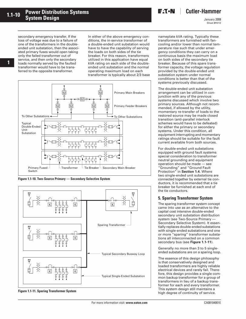
Each transformer secondary is arranged in a typical double-ended unit substation arrangement as shown in Figure 1.1-10. The two secondary main breakers and secondary tie breaker of each unit substation are again either mechanically or electrically interlocked to prevent parallel opera-tion. Upon loss of secondary source voltage on one side, manual or auto-matic transfer may be utilized to transfer the loads to the other side, thus restor-ing power to all secondary loads.
This arrangement permits quick resto-ration of service to all loads when a primary feeder or transformer fault occurs by opening the associated sec-ondary main and closing the second-ary tie breaker. If the loss of secondary voltage has occurred because of a pri-mary feeder fault with the associated primary feeder breaker opening, then all secondary loads normally served by the faulted feeder would have to be transferred to the opposite primary feeder. This means each primary feeder conductor must be sized to carry the load on both sides of all the secondary buses it is serving under
PrimaryFeeders
Load BreakSwitches
Fuses
PrimaryFeeders
Non-Load BreakSelector Switches
Fuses
Load BreakDisconnect
Inter-lock
1.1-10
For more information visit: www.eaton.com CA08104001E
January 2008
Power Distribution Systems
i
ii
1
2
3
4
5
6
7
8
9
10
11
12
13
14
15
16
17
18
19
20
21
Sheet 01
System Design012
secondary emergency transfer. If the loss of voltage was due to a failure of one of the transformers in the double-ended unit substation, then the associ-ated primary fuses would open taking only the failed transformer out of service, and then only the secondary loads normally served by the faulted transformer would have to be trans-ferred to the opposite transformer.
In either of the above emergency con-ditions, the in-service transformer of a double-ended unit substation would have to have the capability of serving the loads on both sides of the tie breaker. For this reason, transformers utilized in this application have equal kVA rating on each side of the double-ended unit substation and the normal operating maximum load on each transformer is typically about 2/3 base
Figure 1.1-10. Two-Source Primary — Secondary Selective System
Figure 1.1-11. Sparing Transformer System
Primary Main Breakers
Primary Feeder Breakers
To Other SubstationsTo Other Substations
Secondary Main BreakerTie BreakerPrimary FusedSwitch
Transformer
TypicalDouble-EndedUnitSubstation
52 52
52
52 52 52 52
KK K
K K
K K
Sparing Transformer
Typical Secondary Busway Loop
Typical Single-Ended Substation
nameplate kVA rating. Typically these transformers are furnished with fan-cooling and/or lower than normal tem-perature rise such that under emer-gency conditions they can carry on a continuous basis the maximum load on both sides of the secondary tie breaker. Because of this spare trans-former capacity, the voltage regulation provided by the double-ended unit substation system under normal conditions is better than that of the systems previously discussed.
The double-ended unit substation arrangement can be utilized in con-junction with any of the previous systems discussed which involve two primary sources. Although not recom-mended, if allowed by the utility, momentary re-transfer of loads to the restored source may be made closed transition (anti-parallel interlock schemes would have to be defeated) for either the primary or secondary systems. Under this condition, all equipment interrupting and momentary ratings should be suitable for the fault current available from both sources.
For double-ended unit substations equipped with ground fault systems special consideration to transformer neutral grounding and equipment operation should be made — see “Grounding” and “Ground Fault Protection” in Section 1.4. Where two single-ended unit substations are connected together by external tie con-ductors, it is recommended that a tie breaker be furnished at each end of the tie conductors.
5. Sparing Transformer SystemThe sparing transformer system concept came into use as an alternative to the capital cost intensive double-ended secondary unit substation distribution system (see Two-Source Primary — Secondary Selective System). It essen-tially replaces double-ended substations with single-ended substations and one or more “sparing” transformer substa-tions all interconnected on a common secondary bus (see Figure 1.1-11).
Generally no more than 3 to 5 single- ended substations are on a sparing loop.
The essence of this design philosophy is that conservatively designed and loaded transformers are highly reliable electrical devices and rarely fail. There-fore, this design provides a single com-mon backup transformer for a group of transformers in lieu of a backup trans-former for each and every transformer. This system design still maintains a high degree of continuity of service.
CA08104001E For more information visit: www.eaton.com
1.1-11January 2008
Power Distribution Systems
i
ii
1
2
3
4
5
6
7
8
9
10
11
12
13
14
15
16
17
18
19
20
21
Sheet 01
System Design013
Referring to Figure 1.1-11, it is appar-ent that the sparing concept backs up primary switch and primary cable fail-ure as well. Restoration of lost or failed utility power is accomplished similarly to primary selective scheme previously discussed. It is therefore important to use an automatic throwover system in a two source lineup of primary switch-gear to restore utility power as dis-cussed in the “Two-Source Primary” scheme — see Figure 1.1-10.
A major advantage of the sparing transformer system is the typically lower total base kVA of transformation. In a double-ended substation design, each transformer must be rated to carry the sum of the loads of two busses and usually requires the addition of cooling fans to accomplish this rating. In the “sparing” concept, each trans-former carries only its own load, which is typically not a fan-cooled rating. Major space savings is also a benefit of this system in addition to first cost savings.
The sparing transformer system operates as follows:
■ All main breakers, including the sparing main breaker are normally closed; the tie breakers are normally open.
■ Once a transformer (or primary cable or primary switch/fuse) fails, the associated secondary main breaker is opened. The associated tie breaker is then closed, which restores power to the single-ended substation bus.
■ Schemes which require the main to be opened before the tie is closed (“open transition”), and which allow any tie to be closed before the substation main is opened, (“closed transition”) are possible.
With a closed transition scheme it is common to add a timer function that opens the tie breaker unless either main breaker is opened within a time interval. This closed transition allows power to be transferred to the sparing transformer without interruption, such as for routine maintenance, and then back to the substation. This closed transition transfer has an advantage in some facilities, however, appropriate interrupting capacities and bus bracing must be specified suitable for the momentary parallel operation.
In facilities with no qualified electrical power operators, an open transition with key interlocking is often a prudent design.
Note: Each pair of “main breaker/tie breaker” key cylinders should be uniquely keyed to prevent any paralleled source operations.
Careful sizing of these transformers as well as careful specification of the transformers is required for reliability. Low temperature rise specified with continuous overload capacity or upgraded types of transformers should be considered.
One disadvantage to this system is the external secondary tie system, see Figure 1.1-11. As shown, all single-ended substations are tied together on the secondary with a tie busway or cable system. Location of substations is therefore limited because of voltage drop and cost considerations.
Routing of busway, if used, must be carefully layed out. It should also be noted, that a tie busway or cable fault will essentially prevent the use of the sparing transformer until it is repaired. Commonly, the single-ended substa-tions and the sparing transformer must be clustered. This can also be an advantage, as more kVA can be supported from a more compact space layout.
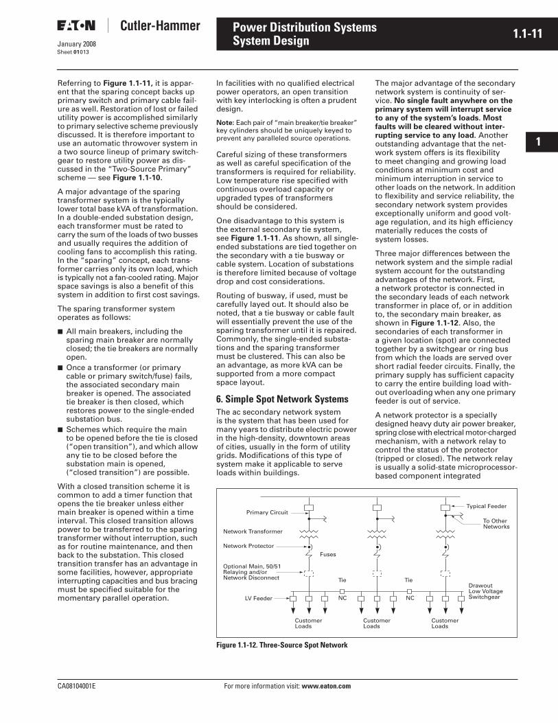
6. Simple Spot Network SystemsThe ac secondary network system is the system that has been used for many years to distribute electric power in the high-density, downtown areas of cities, usually in the form of utility grids. Modifications of this type of system make it applicable to serve loads within buildings.
The major advantage of the secondary network system is continuity of ser-vice. No single fault anywhere on the primary system will interrupt service to any of the system’s loads. Most faults will be cleared without inter-rupting service to any load. Another outstanding advantage that the net-work system offers is its flexibility to meet changing and growing load conditions at minimum cost and minimum interruption in service to other loads on the network. In addition to flexibility and service reliability, the secondary network system provides exceptionally uniform and good volt-age regulation, and its high efficiency materially reduces the costs of system losses.
Three major differences between the network system and the simple radial system account for the outstanding advantages of the network. First, a network protector is connected in the secondary leads of each network transformer in place of, or in addition to, the secondary main breaker, as shown in Figure 1.1-12. Also, the secondaries of each transformer in a given location (spot) are connected together by a switchgear or ring bus from which the loads are served over short radial feeder circuits. Finally, the primary supply has sufficient capacity to carry the entire building load with-out overloading when any one primary feeder is out of service.
A network protector is a specially designed heavy duty air power breaker, spring close with electrical motor-charged mechanism, with a network relay to control the status of the protector (tripped or closed). The network relay is usually a solid-state microprocessor-based component integrated
Figure 1.1-12. Three-Source Spot Network
CustomerLoads
CustomerLoads
CustomerLoads
NC NC
TieTie
Typical Feeder
To OtherNetworks
DrawoutLow VoltageSwitchgear
Fuses
Primary Circuit
Network Transformer
Network Protector
Optional Main, 50/51Relaying and/orNetwork Disconnect
LV Feeder
1.1-12
For more information visit: www.eaton.com CA08104001E
January 2008
Power Distribution Systems
i
ii
1
2
3
4
5
6
7
8
9
10
11
12
13
14
15
16
17
18
19
20
21
Sheet 01
System Design014
into the protector enclosure which functions to automatically close the protector only when the voltage conditions are such that its associated transformer will supply power to the secondary network loads, and to auto-matically open the protector when power flows from the secondary to the network transformer. The purpose of the network protector is to protect the integrity of the network bus voltage and the loads served from it against transformer and primary feeder faults by quickly disconnecting the defective feeder-transformer pair from the network when backfeed occurs.
The simple spot network system resembles the secondary-selective radial system in that each load area is supplied over two or more primary feeders through two or more trans-formers. In network systems, the transformers are connected through network protectors to a common bus, as shown in Figure 1.1-12, from which loads are served. Since the transform-ers are connected in parallel, a primary feeder or transformer fault does not cause any service interruption to the loads. The paralleled transformers supplying each load bus will normally carry equal load currents, whereas equal loading of the two separate transformers supplying a substation in the secondary-selective radial system is difficult to obtain. The interrupting duty imposed on the outgoing feeder breakers in the network will be greater with the spot network system.
The optimum size and number of pri-mary feeders can be used in the spot network system because the loss of any primary feeder and its associated transformers does not result in the loss of any load even for an instant. In spite of the spare capacity usually supplied in network systems, savings in primary switchgear and secondary switchgear costs often result when compared to a radial system design with similar spare capacity. This occurs in many radial systems because more and smaller feeders are often used in order to minimize the extent of any outage when a primary fault event occurs.
In spot networks, when a fault occurs on a primary feeder or in a transformer, the fault is isolated from the system through the automatic tripping of the primary feeder circuit breaker and all of the network protectors associated
with that feeder circuit. This operation does not interrupt service to any loads. After the necessary repairs have been made, the system can be restored to normal operating conditions by closing the primary feeder breaker. All network protectors associated with that feeder will close automatically.
The chief purpose of the network bus normally closed ties is to provide for the sharing of loads and a balancing of load currents for each primary ser-vice and transformer regardless of the condition of the primary services.
Also, the ties provide a means for isolating and sectionalizing ground fault events within the switchgear network bus, thereby saving a portion of the loads from service interruptions, yet isolating the faulted portion for corrective action.
The use of spot network systems provides users with several important advantages. First, they save trans-former capacity. Spot networks permit equal loading of transformers under all conditions. Also, networks yield lower system losses and greatly improve voltage conditions. The volt-age regulation on a network system is such that both lights and power can be fed from the same load bus. Much larger motors can be started across-the-line than on a simple radial system. This can result in simplified motor control and permits the use of relatively large low voltage motors with their less expensive control. Finally, network systems provide a greater degree of flexibility in adding future loads; they can be connected to the closest spot network bus.
Spot network systems are economical for buildings which have heavy con-centrations of loads covering small areas, with considerable distance between areas, and light loads within the distances separating the concen-trated loads. They are commonly used in hospitals, high rise office buildings, and institutional buildings where a high degree of service reliability is required from the utility sources. Spot network systems are especially eco-nomical where three or more primary feeders are available. Principally, this is due to supplying each load bus through three or more transformers and the reduction in spare cable and transformer capacity required.
They are also economical when compared to two transformer double-ended substations with normally opened tie breakers.
Emergency power should be connected to network loads downstream from the network, or upstream at primary voltage, not at the network bus itself.
7. Medium Voltage Distribution System Design
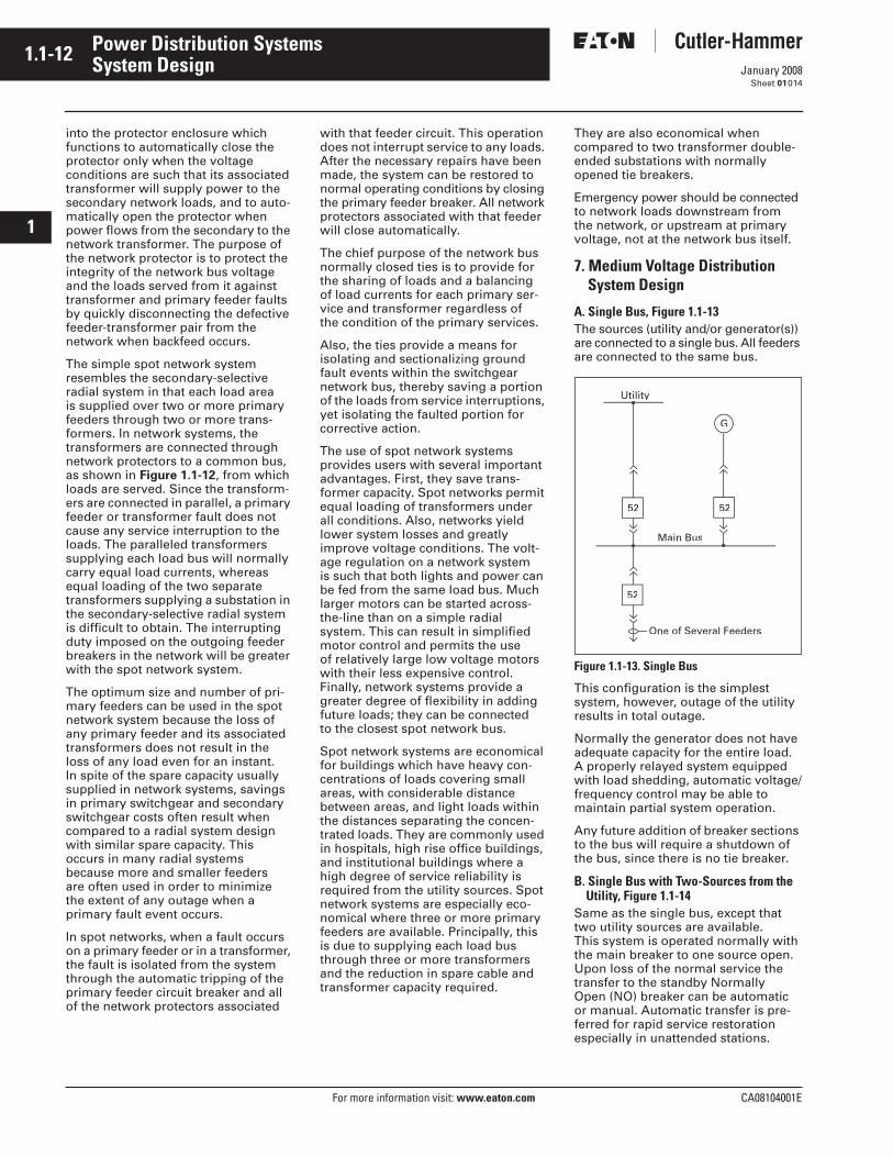
A. Single Bus, Figure 1.1-13The sources (utility and/or generator(s)) are connected to a single bus. All feeders are connected to the same bus.
Figure 1.1-13. Single Bus
This configuration is the simplest system, however, outage of the utility results in total outage.
Normally the generator does not have adequate capacity for the entire load. A properly relayed system equipped with load shedding, automatic voltage/frequency control may be able to maintain partial system operation.
Any future addition of breaker sections to the bus will require a shutdown of the bus, since there is no tie breaker.
B. Single Bus with Two-Sources from the Utility, Figure 1.1-14
Same as the single bus, except that two utility sources are available. This system is operated normally with the main breaker to one source open. Upon loss of the normal service the transfer to the standby Normally Open (NO) breaker can be automatic or manual. Automatic transfer is pre-ferred for rapid service restoration especially in unattended stations.
52
Utility
Main Bus
G
One of Several Feeders
52
52
CA08104001E For more information visit: www.eaton.com
1.1-13January 2008
Power Distribution Systems
i
ii
1
2
3
4
5
6
7
8
9
10
11
12
13
14
15
16
17
18
19
20
21
Sheet 01
System Design015
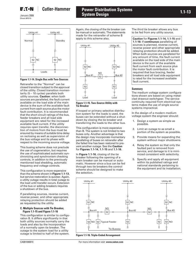
Figure 1.1-14. Single Bus with Two-Sources
Retransfer to the “Normal” can be closed transition subject to the approval of the utility. Closed transition momen-tarily (5 – 10 cycles) parallels both utility sources. Caution: when both sources are paralleled, the fault current available on the load side of the main device is the sum of the available fault current from each source plus the motor fault contribution. It is recommended that the short circuit ratings of the bus, feeder breakers and all load side equipment are rated for the increased available fault current. If the utility requires open transfer, the disconnec-tion of motors from the bus must be ensured by means of suitable time delay on reclosing as well as supervision of the bus voltage and its phase with respect to the incoming source voltage.
This busing scheme does not preclude the use of cogeneration, but requires the use of sophisticated automatic syn-chronizing and synchronism checking controls, in addition to the previously mentioned load shedding, automatic frequency and voltage controls.
This configuration is more expensive than the scheme shown in Figure 1.1-13, but service restoration is quicker. Again, a utility outage results in total outage to the load until transfer occurs. Extension of the bus or adding breakers requires a shutdown of the bus.
If paralleling sources, reverse current, reverse power, and other appropriate relaying protection should be added as requested by the utility.
C. Multiple Sources with Tie Breaker, Figure 1.1-15 and Figure 1.1-16
This configuration is similar to configu-ration B. It differs significantly in that both utility sources normally carry the loads and also by the incorporation of a normally open tie breaker. The outage to the system load for a utility outage is limited to half of the system.
Utility #2Utility #1
Normal Standby
NC NO
Loads
52 52
Again, the closing of the tie breaker can be manual or automatic. The statements made for the retransfer of scheme B apply to this scheme also.
Figure 1.1-15. Two-Source Utility withTie Breaker
If looped or primary selective distribu-tion system for the loads is used, the buses can be extended without a shut-down by closing the tie breaker and transferring the loads to the other bus.
This configuration is more expensive than B. The system is not limited to two buses only. Another advantage is that the design may incorporate momentary paralleling of buses on retransfer after the failed line has been restored to pre-vent another outage. See the Caution for Figures 1.1-14, 1.1-15 and 1.1-16.
In Figure 1.1-16, closing of the tie breaker following the opening of a main breaker can be manual or auto-matic. However since a bus can be fed through two tie breakers the control scheme should be designed to make the selection.
The third tie breaker allows any bus to be fed from any utility source.
SummaryThe medium voltage system configura-tions shown are based on using metal-clad drawout switchgear. The service continuity required from electrical sys-tems makes the use of single source systems impractical.
In the design of a modern medium voltage system the engineer should:
1. Design a system as simple as possible.
2. Limit an outage to as small a portion of the system as possible.
3. Provide means for expanding the system without major shutdowns.
4. Relay the system so that only the faulted part is removed from service, and damage to it is mini-mized consistent with selectivity.
5. Specify and apply all equipment within its published ratings and national standards pertaining to the equipment and its installation.
Figure 1.1-16. Triple-Ended Arrangement
Utility #1
NC
Bus #1 Bus #2
Load Load
Utility #2
NC
NO
52 52
52
52 52
Caution for Figures 1.1-14, 1.1-15 and 1.1-16: If continuous paralleling of sources is planned, reverse current, reverse power and other appropriate relaying protection should be added. When both sources are paralleled for any amount of time, the fault current available on the load side of the main device is the sum of the available fault current from each source plus the motor fault contribution. It is required that bus bracing, feeder breakers and all load side equipment is rated for the increased available fault current.
NO
NC
Bus #1 Bus #2
Utility #1 Utility #2
NC
NO NO
Utility #3
Bus #3
NC
Tie Busway
52 52 52
52
52
52
52 NOTypical Feeder52 5252
1.1-14
For more information visit: www.eaton.com CA08104001E
January 2008
Power Distribution Systems
i
ii
1
2
3
4
5
6
7
8
9
10
11
12
13
14
15
16
17
18
19
20
21
Sheet 01
System Design016
Health Care FacilitiesHealth Care Facilities are defined by NFPA (National Fire Protection Agency) as “Buildings or portions of buildings in which medical, dental, psychiatric, nursing, obstetrical, or surgical care are provided.” Due to the critical nature of the care being provided at these facilities and their increasing dependence on electrical equipment for preservation of life, health care facilities have special requirements for the design of their electrical distribu-tion systems. These requirements are typically much more stringent than commercial or industrial facilities. The following section summarizes some of the unique requirements of health care facility design.
There are several agencies and organi-zations that develop requirements for health care electrical distribution sys-tem design. The following is a listing of some of the specific NFPA (National Fire Protection Agency) standards that affect health care facility design and implementation:
■ NFPA 37 — Standard for Stationary Combustion Engines and Gas Turbines.
■ NFPA 70 — National Electrical Code.■ NFPA 99 — Health Care Facilities.
■ NFPA 101 — Life Safety Code.■ NFPA 110 — Standard for Emergency
and Standby Power Systems.■ NFPA 111 — Standard on Stored
Electrical Energy Emergency and Standby Power Systems.
These NFPA guidelines represent the most industry recognized standard requirements for health care electrical design. However, the electrical design engineer should consult with the authorities having jurisdiction over the local region for specific electrical distribution requirements.
Health Care Electrical System RequirementsHealth care electrical systems usually consist of two parts:
1. Non-essential or Normal Electrical System.
2. Essential Electrical System.
All electrical power in a health care facility is important, though some loads are not critical to the safe opera-tion of the facility. These “non-essential” or “normal” loads include things such as general lighting, general lab equip-ment, non-critical service equipment, patient care areas, etc. These loads are not required to be fed from an alter-nate source of power.
The electrical system requirements for the Essential Electrical System (EES) vary according to the type of health care facility. Health care facilities are categorized by NFPA 99 as Type 1, Type 2 or, Type 3 facilities. Some example health care facilities, classi-fied by Type, are summarized in the following Table 1.1-8.
Table 1.1-8. Health Care Facilities
� If electrical life support or critical care areas are present then facility is classified as Type 1.
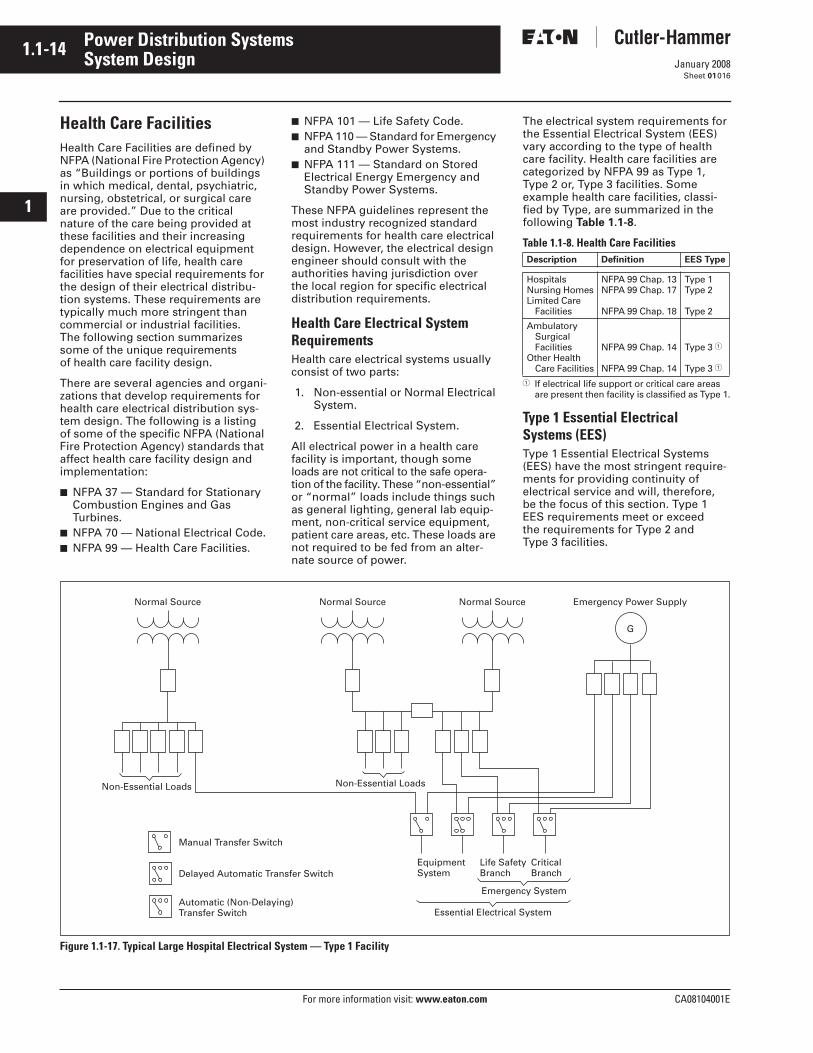
Type 1 Essential Electrical Systems (EES)Type 1 Essential Electrical Systems (EES) have the most stringent require-ments for providing continuity of electrical service and will, therefore,be the focus of this section. Type 1 EES requirements meet or exceed the requirements for Type 2 and Type 3 facilities.
Figure 1.1-17. Typical Large Hospital Electrical System — Type 1 Facility
Description Definition EES Type
HospitalsNursing HomesLimited Care
Facilities
NFPA 99 Chap. 13NFPA 99 Chap. 17
NFPA 99 Chap. 18
Type 1Type 2
Type 2
Ambulatory SurgicalFacilities
Other Health Care Facilities
NFPA 99 Chap. 14
NFPA 99 Chap. 14
Type 3 �
Type 3 �
Normal Source Normal Source
G
Non-Essential Loads Non-Essential Loads
Essential Electrical System
Manual Transfer Switch
Normal Source Emergency Power Supply
Life SafetyBranch
CriticalBranch
Emergency System
EquipmentSystemDelayed Automatic Transfer Switch
Automatic (Non-Delaying)Transfer Switch
CA08104001E For more information visit: www.eaton.com
1.1-15January 2008
Power Distribution Systems
i
ii
1
2
3
4
5
6
7
8
9
10
11
12
13
14
15
16
17
18
19
20
21
Sheet 01
System Design017
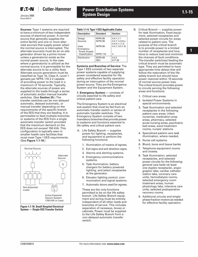
Sources: Type 1 systems are required to have a minimum of two independent sources of electrical power. A normal source that generally supplies the entire facility and one or more alter-nate sources that supply power when the normal source is interrupted. The alternate source(s) must be an on-site generator driven by a prime mover unless a generator(s) exists as the normal power source. In the case where a generator(s) is utilized as the normal source, it is permissible for the alternate source to be a utility feed. Alternate source generators must be classified as Type 10, Class X, Level 1 gensets per NFPA 110 2-2 capable of providing power to the load in a maximum of 10 seconds. Typically, the alternate sources of power are supplied to the loads through a series of automatic and/or manual transfer switches. (See Section 25.) The transfer switches can be non-delayed automatic, delayed automatic, or manual transfer depending on the requirements of the specific branch of the EES that they are feeding. It is permissible to feed multiple branches or systems of the EES from a single automatic transfer switch provided that the maximum demand on the EES does not exceed 150 kVA. This configuration is typically seen in smaller health care facilities that must meet Type 1 EES requirements. (See Figure 1.1-18.)
Figure 1.1-18. Small Hospital Electrical System — Single EES Transfer Switch
Table 1.1-9. Type 1 EES Applicable Codes
Systems and Branches of Service: The Type 1 EES consists of two separate power systems capable of supplying power considered essential for life safety and effective facility operation during an interruption of the normal power source. They are the Emergency System and the Equipment System.
1. Emergency System — consists of circuits essential to life safety and critical patient care.
The Emergency System is an electrical sub-system that must be fed from an automatic transfer switch or series of automatic transfer switches. This Emergency System consists of two mandatory branches that provide power to systems and functions essential to life safety and critical patient care.
A. Life Safety Branch — supplies power for lighting, receptacles, and equipment to perform the following functions:
1. Illumination of means of egress.2. Exit signs and exit direction signs.3. Alarms and alerting systems.4. Emergency communications
systems.5. Task illumination, battery
chargers for battery powered lighting, and select receptacles at the generator.
6. Elevator lighting control, com-munication and signal systems.
7. Automatic doors used for egress.
These are the only functions permitted to be on the life safety branch. Life Safety Branch equip-ment and wiring must be entirely independent of all other loads and branches of service. This includes separation of raceways, boxes or cabinets. Power must be supplied to the Life Safety Branch from a non-delayed automatic transfer switch.
B. Critical Branch — supplies power for task illumination, fixed equip-ment, selected receptacles and selected power circuits for areas related to patient care. The purpose of the critical branch is to provide power to a limited number of receptacles and loca-tions to reduce load and minimize the chances of fault conditions. The transfer switch(es) feeding the critical branch must be automatic type. They are permitted to have appropriate time delays that will follow the restoration of the life safety branch but should have power restored within 10 seconds of normal source power loss. The critical branch provides power to circuits serving the following areas and functions:
1. Critical care areas.2. Isolated Power Systems in
special environments.3. Task illumination and selected
receptacles in the following patient care areas: infant nurseries, medication prep areas, pharmacy, selected acute nursing areas, psychiatric bed areas, ward treatment rooms, nurses’ stations.
4. Specialized patient care task illumination, where needed.
5. Nurse call systems.6. Blood, bone and tissue banks.7. Telephone equipment rooms
and closets.8. Task illumination, selected
receptacles, and selected power circuits for the following: general care beds (at least one duplex receptacle), angio-graphic labs, cardiac catheter-ization labs, coronary care units, hemodialysis rooms, selected emergency room treatment areas, human physiology labs, intensive care units, selected postoperative recovery rooms.
9. Additional circuits and single-phase fraction motors as needed for effective facility operation.
Normal Source
G
Non-EssentialLoads
AlternateSource
Entire EssentialElectric System(150 kVA or Less)
Description Standard Section
DesignSources
UsesEmergency Power Supply Classification
NFPA 99NFPA 99
NFPA 99
NFPA 110
4.4.1.1.14.4.1.1.4 thru 4.4.4.1.1.7.24.4.1.1.8 (1-3)
4
Distribution NFPA 99NEC
4.4.2517-30
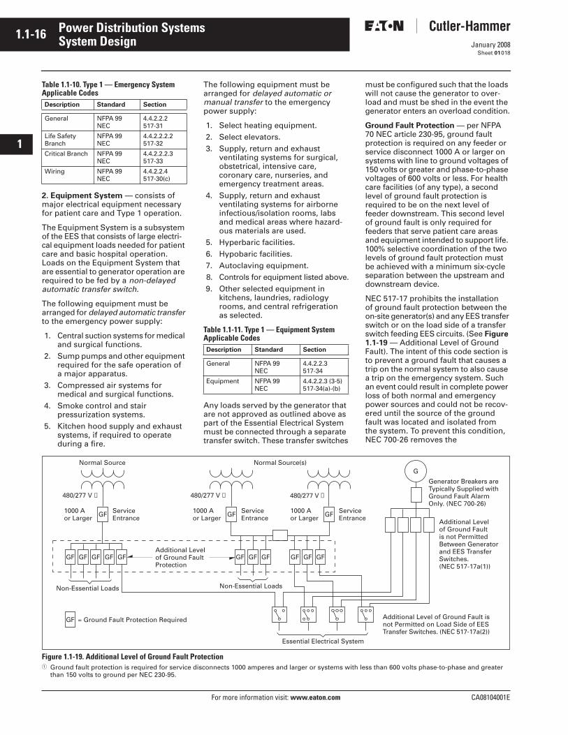
1.1-16
For more information visit: www.eaton.com CA08104001E
January 2008
Power Distribution Systems
i
ii
1
2
3
4
5
6
7
8
9
10
11
12
13
14
15
16
17
18
19
20
21
Sheet 01
System Design018
Table 1.1-10. Type 1 — Emergency System Applicable Codes
2. Equipment System — consists of major electrical equipment necessary for patient care and Type 1 operation.
The Equipment System is a subsystem of the EES that consists of large electri-cal equipment loads needed for patient care and basic hospital operation. Loads on the Equipment System that are essential to generator operation are required to be fed by a non-delayed automatic transfer switch.
The following equipment must be arranged for delayed automatic transfer to the emergency power supply:
1. Central suction systems for medical and surgical functions.
2. Sump pumps and other equipment required for the safe operation of a major apparatus.
3. Compressed air systems for medical and surgical functions.
4. Smoke control and stair pressurization systems.
5. Kitchen hood supply and exhaust systems, if required to operate during a fire.
The following equipment must be arranged for delayed automatic or manual transfer to the emergency power supply:
1. Select heating equipment.2. Select elevators.3. Supply, return and exhaust
ventilating systems for surgical, obstetrical, intensive care, coronary care, nurseries, and emergency treatment areas.
4. Supply, return and exhaust ventilating systems for airborne infectious/isolation rooms, labs and medical areas where hazard-ous materials are used.
5. Hyperbaric facilities.6. Hypobaric facilities.7. Autoclaving equipment.8. Controls for equipment listed above.9. Other selected equipment in
kitchens, laundries, radiology rooms, and central refrigeration as selected.
Table 1.1-11. Type 1 — Equipment System Applicable Codes
Any loads served by the generator that are not approved as outlined above as part of the Essential Electrical System must be connected through a separate transfer switch. These transfer switches
must be configured such that the loads will not cause the generator to over-load and must be shed in the event the generator enters an overload condition.
Ground Fault Protection — per NFPA 70 NEC article 230-95, ground fault protection is required on any feeder or service disconnect 1000 A or larger on systems with line to ground voltages of 150 volts or greater and phase-to-phase voltages of 600 volts or less. For health care facilities (of any type), a second level of ground fault protection is required to be on the next level of feeder downstream. This second level of ground fault is only required for feeders that serve patient care areas and equipment intended to support life. 100% selective coordination of the two levels of ground fault protection must be achieved with a minimum six-cycle separation between the upstream and downstream device.
NEC 517-17 prohibits the installation of ground fault protection between the on-site generator(s) and any EES transfer switch or on the load side of a transfer switch feeding EES circuits. (See Figure 1.1-19 — Additional Level of Ground Fault). The intent of this code section is to prevent a ground fault that causes a trip on the normal system to also cause a trip on the emergency system. Such an event could result in complete power loss of both normal and emergency power sources and could not be recov-ered until the source of the ground fault was located and isolated from the system. To prevent this condition, NEC 700-26 removes the
Figure 1.1-19. Additional Level of Ground Fault Protection� Ground fault protection is required for service disconnects 1000 amperes and larger or systems with less than 600 volts phase-to-phase and greater
than 150 volts to ground per NEC 230-95.
Description Standard Section
General NFPA 99NEC
4.4.2.2.2517-31
Life Safety Branch
NFPA 99NEC
4.4.2.2.2.2517-32
Critical Branch NFPA 99NEC
4.4.2.2.2.3517-33
Wiring NFPA 99NEC
4.4.2.2.4517-30(c)
Description Standard Section
General NFPA 99NEC
4.4.2.2.3517-34
Equipment NFPA 99NEC
4.4.2.2.3 (3-5)517-34(a)-(b)
Normal Source Normal Source(s)G
480/277 V ➀
ServiceEntrance
1000 Aor Larger GFService
Entrance1000 Aor Larger GF
480/277 V ➀
GFGFGF GFGFGFGFGFGF GFGF
ServiceEntrance
1000 Aor Larger GF
480/277 V ➀
GF
Non-Essential Loads Non-Essential Loads
Essential Electrical System
Additional Levelof Ground FaultProtection
Additional Levelof Ground Faultis not PermittedBetween Generatorand EES TransferSwitches.(NEC 517-17a(1))
Additional Level of Ground Fault isnot Permitted on Load Side of EESTransfer Switches. (NEC 517-17a(2))
= Ground Fault Protection Required
Generator Breakers areTypically Supplied withGround Fault AlarmOnly. (NEC 700-26)
CA08104001E For more information visit: www.eaton.com
1.1-17January 2008
Power Distribution Systems
i
ii
1
2
3
4
5
6
7
8
9
10
11
12
13
14
15
16
17
18
19
20
21
Sheet 01
System Design019
ground fault protection requirement for the emergency system source. Typically, the emergency system generator(s) are equipped with ground fault alarms that do not automatically disconnect during a ground fault.
Table 1.1-12. Ground Fault Protection Applicable Codes
Wet Locations — A wet location in a health care facility is any patient care area that is normally subject to wet conditions while patients are present. Typical wet locations can include oper-ating rooms, anesthetizing locations, dialysis locations, etc. (Patient beds, toilets, sinks, are not considered wet locations.) These wet locations require special protection to guard against electric shock. The ground fault current in these areas must be limited not to exceed 6 mA.
In areas where the interruption of power is permissible, ground fault circuit interrupters (GFCI) can be employed. GFCIs will interrupt a circuit when ground fault current exceeds the present level (typically 2-5 mA).
In areas where the interruption of power cannot be tolerated, protection from ground fault currents is accom-plished through the use of an Isolated Power System. Isolated Power Sys-tems provide power to an area that is isolated from ground (or ungrounded). This type of system limits the amount of current that flows to ground in the event of a single line-to-ground fault and maintains circuit continuity. Electronic Line Isolation Monitors (LIM) are used to monitor and display leakage currents to ground. When leakage current thresholds are exceeded, visible and/or audible alarms are initiated to alert occupants of a possible hazardous condition. This alarm occurs without interrupting power to allow for the safe conclusion of critical procedures.
Table 1.1-13. Wet Location Applicable Codes
Maintenance and TestingRegular maintenance and testing of the electrical distribution system in a health care facility is necessary to ensure proper operation in an emer-gency and, in some cases, to maintain government accreditation. Any health care facility receiving Medicare or Medicaid reimbursement from the government must be accredited by the Joint Commission on Accreditation of Health Care Organizations (JCAHO). JCAHO has established a group of standards called the Environment of Care, which must be met for health care facility accreditation. Included in these standards is the regular testing of the emergency (alternate) power system(s). The emergency power sys-tem must be tested in accordance with NFPA 110 Standard for Emergency and Standby Power Systems guidelines at intervals not less than 20 days and not exceeding 40 days. Generators must be tested for a minimum of 30 minutes under the criteria defined in NFPA 110.
One method to automate the task of monthly generator tests is through the use of PowerNet� communications. With the PowerNet integrated metering, monitoring and control system, a facility maintenance director can initiate a generator test, control/monitor loads, meter/monitor generator test points and create a JCAHO compliant report automatically from a central PC. The report contains all metered values, test results, date/time information, etc. necessary to satisfy JCAHO require-ments. This automated generator testing procedure reduces the labor, training and inaccuracies that occur during manual emergency power system tests. (See Power Monitoring Section 2.)
Table 1.1-14. Maintenance and Testing Applicable Codes
Routine maintenance should be per-formed on circuit breakers, transfer switches, switchgear, generator equip-ment, etc. by trained professionals to ensure the most reliable electrical system possible. See Section 43 for Eaton - Electrical Services & Systems E-ESS), which provides engineers,
trained in development and execution of annual preventative maintenance procedures of health care facility electrical distribution systems.
Paralleling Emergency Generators
Without Utility ParallelingIn many health care facilities (and other large facilities with critical loads), the demand for standby emergency power is large enough to require multiple generator sets to power all of the required Essential Electrical System (EES) loads. In many cases, it becomes more flexible and easier to operate the required multiple generators from a single location utilizing Generator Paralleling Switch-gear. Figure 1.1-20 on Page 1.1-18 shows an example of a typical one-line for a paralleling switchgear lineup feeding the EES.
A typical abbreviated sequence of operation for a multiple emergency generator and ATS system follows. Note that other modes of operation such as generator demand priority and automated testing modes are available but are not included below. (Reference Section 43 for complete detailed sequences of operation.)
1. Entering Emergency Mode
a. Upon loss of normal source, automatic transfer switches send generator control system a run request.
b. All available generators are started. The first generator up to voltage and frequency is closed to the bus.
c. Unsheddable loads and Load Shed Priority 1 loads are pow-ered in less than 10 seconds.
d. The remaining generators are synchronized and paralleled to the bus as they come up to voltage and frequency.
e. As additional generators are paralleled to the emergency bus, Load Shed Priority levels are added, powering their associated loads.
f. The system is now in Emergency Mode.
2. Exit from Emergency Mode
a. Automatic transfer switches sense the utility source is within acceptable operational toler-ances for a time duration set at the automatic transfer switch.
Description Standard Section
ServicesFeeders
NECNEC
230-95215-10
Additional Level NECNFPA 99
517-174.3.2.5
Alternate Source NECNEC
700-26700-7 (d)
Description Standard Section
General NFPA 99NEC
4.3.2.2.9517-20
Isolated Power Systems
NFPA 99NEC
4.3.2.6517-160
Description Standard Section
Grounding NFPA 99 4.3.3.1
Emergency Power System
NFPA 99JCAHO
4.4.4.1.1EC.2.14(d)
Generator NFPA 110 8.4.2
Transfer Switches NFPA 110 8.4.5
Breakers NFPA 99NFPA 110
4.4.4.1.28.4.6
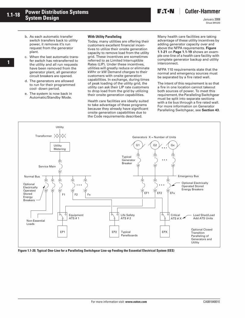
1.1-18
For more information visit: www.eaton.com CA08104001E
January 2008
Power Distribution Systems
i
ii
1
2
3
4
5
6
7
8
9
10
11
12
13
14
15
16
17
18
19
20
21
Sheet 01
System Design020
b. As each automatic transfer switch transfers back to utility power, it removes it’s run request from the generator plant.
c. When the last automatic trans-fer switch has retransferred to the utility and all run requests have been removed from the generator plant, all generator circuit breakers are opened.
d. The generators are allowed to run for their programmed cool- down period.
e. The system is now back in Automatic/Standby Mode.
With Utility ParallelingToday, many utilities are offering their customers excellent financial incen-tives to utilize their onsite generation capacity to remove load from the utility grid. These incentives are sometimes referred to as Limited Interruptible Rates (LIP). Under these incentives, utilities will greatly reduce or eliminate kWhr or kW Demand charges to their customers with onsite generation capabilities. In exchange, during times of peak loading of the utility grid, the utility can ask their LIP rate customers to drop load from the grid by utilizing their onsite generation capabilities.
Health care facilities are ideally suited to take advantage of these programs because they already have significant onsite generation capabilities due to the Code requirements described.
Many health care facilities are taking advantage of these utility incentives by adding generator capacity over and above the NFPA requirements. Figure 1.1-21 on Page 1.1-19 shows an exam-ple one-line of a health care facility with complete generator backup and utility interconnect.
NFPA 110 requirements state that the normal and emergency sources must be separated by a fire rated wall.
The intent of this requirement is so that a fire in one location cannot takeout both sources of power. To meet this requirement, the Paralleling Switchgear must be split into separate sections with a tie bus through a fire rated wall. For more information on Generator Paralleling Switchgear, see Section 43.
Figure 1.1-20. Typical One-Line for a Paralleling Switchgear Line-up Feeding the Essential Electrical System (EES)
UtilityMetering
Utility
Transformer
Service Main
Normal Bus
OptionalElectricallyOperatedStoredEnergyBreakers
Non-EssentialLoads
EP1 EP2 EPX
FxF2F1 EFxEF2EF1
Generators X = Number of Units
TypicalGeneratorBreaker
Emergency Bus
EquipmentATS # 1
Life SafetyATS # 2
CriticalATS # X
TypicalPanelboards
GxG2G1
Optional ElectricallyOperated StoredEnergy Breakers
Load Shed/LoadAdd ATS Units
Optional ClosedTransitionParalleling ofGenerators andUtility
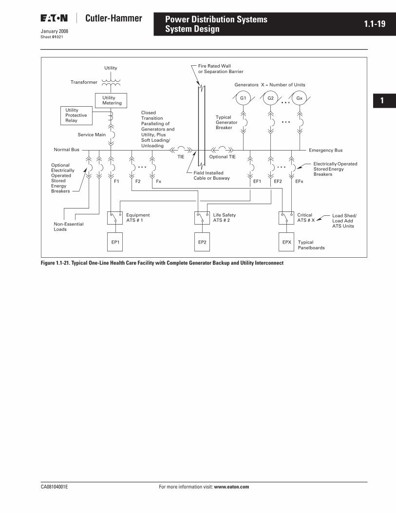
CA08104001E For more information visit: www.eaton.com
1.1-19January 2008
Power Distribution Systems
i
ii
1
2
3
4
5
6
7
8
9
10
11
12
13
14
15
16
17
18
19
20
21
Sheet 01
System Design021
Figure 1.1-21. Typical One-Line Health Care Facility with Complete Generator Backup and Utility Interconnect
Utility
Transformer
UtilityMetering
Generators X = Number of Units
TypicalGeneratorBreaker
GxG2G1
Emergency Bus
Electrically OperatedStored EnergyBreakers
EFxEF2EF1
Service Main
Normal Bus
OptionalElectricallyOperatedStoredEnergyBreakers
FxF2F1
Non-EssentialLoads
EquipmentATS # 1
Life SafetyATS # 2
CriticalATS # X
Load Shed/Load AddATS Units
TypicalPanelboards
EP1 EP2 EPX
UtilityProtectiveRelay
TIE Optional TIE
Fire Rated Wallor Separation Barrier
Field InstalledCable or Busway
ClosedTransitionParalleling ofGenerators andUtility, PlusSoft Loading/Unloading

1.1-20
For more information visit: www.eaton.com CA08104001E
January 2008
Power Distribution Systems
i
ii
1
2
3
4
5
6
7
8
9
10
11
12
13
14
15
16
17
18
19
20
21
Sheet 01022
This page intentionally left blank.
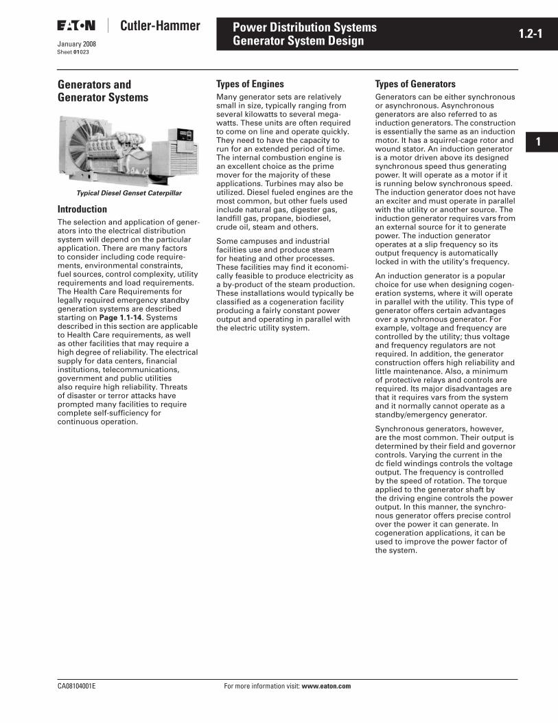
CA08104001E For more information visit: www.eaton.com
1.2-1January 2008
Power Distribution Systems
i
ii
1
2
3
4
5
6
7
8
9
10
11
12
13
14
15
16
17
18
19
20
21
Sheet 01
Generator System Design023
Generators and Generator Systems
Typical Diesel Genset Caterpillar
IntroductionThe selection and application of gener-ators into the electrical distribution system will depend on the particular application. There are many factors to consider including code require-ments, environmental constraints, fuel sources, control complexity, utility requirements and load requirements. The Health Care Requirements for legally required emergency standby generation systems are described starting on Page 1.1-14. Systems described in this section are applicable to Health Care requirements, as well as other facilities that may require a high degree of reliability. The electrical supply for data centers, financial institutions, telecommunications, government and public utilities also require high reliability. Threats of disaster or terror attacks have prompted many facilities to require complete self-sufficiency for continuous operation.
Types of EnginesMany generator sets are relatively small in size, typically ranging from several kilowatts to several mega-watts. These units are often required to come on line and operate quickly. They need to have the capacity to run for an extended period of time. The internal combustion engine is an excellent choice as the prime mover for the majority of these applications. Turbines may also be utilized. Diesel fueled engines are the most common, but other fuels used include natural gas, digester gas, landfill gas, propane, biodiesel, crude oil, steam and others.
Some campuses and industrial facilities use and produce steamfor heating and other processes. These facilities may find it economi-cally feasible to produce electricity as a by-product of the steam production. These installations would typically be classified as a cogeneration facility producing a fairly constant power output and operating in parallel with the electric utility system.
Types of GeneratorsGenerators can be either synchronous or asynchronous. Asynchronous generators are also referred to as induction generators. The construction is essentially the same as an induction motor. It has a squirrel-cage rotor and wound stator. An induction generator is a motor driven above its designed synchronous speed thus generating power. It will operate as a motor if itis running below synchronous speed. The induction generator does not have an exciter and must operate in parallel with the utility or another source. The induction generator requires vars from an external source for it to generate power. The induction generator operates at a slip frequency so its output frequency is automatically locked in with the utility's frequency.
An induction generator is a popular choice for use when designing cogen-eration systems, where it will operate in parallel with the utility. This type of generator offers certain advantages over a synchronous generator. For example, voltage and frequency are controlled by the utility; thus voltage and frequency regulators are not required. In addition, the generator construction offers high reliability and little maintenance. Also, a minimum of protective relays and controls are required. Its major disadvantages are that it requires vars from the system and it normally cannot operate as a standby/emergency generator.
Synchronous generators, however, are the most common. Their output is determined by their field and governor controls. Varying the current in the dc field windings controls the voltage output. The frequency is controlled by the speed of rotation. The torque applied to the generator shaft by the driving engine controls the power output. In this manner, the synchro-nous generator offers precise control over the power it can generate. In cogeneration applications, it can be used to improve the power factor of the system.
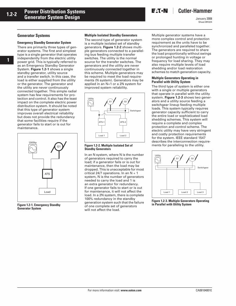
1.2-2
For more information visit: www.eaton.com CA08104001E
January 2008
Power Distribution Systems
i
ii
1
2
3
4
5
6
7
8
9
10
11
12
13
14
15
16
17
18
19
20
21
Sheet 01
Generator System Design024
Generator Systems
Emergency Standby Generator SystemThere are primarily three types of gen-erator systems. The first and simplest type is a single generator that operates independently from the electric utility power grid. This is typically referred to as an Emergency Standby Generator System. Figure 1.2-1 shows a single standby generator, utility source and a transfer switch. In this case, the load is either supplied from the utility or the generator. The generator and the utility are never continuously connected together. This simple radial system has few requirements for pro-tection and control. It also has the least impact on the complete electric power distribution system. It should be noted that this type of generator system improves overall electrical reliability but does not provide the redundancy that some facilities require if the generator fails to start or is out for maintenance.
Figure 1.2-1. Emergency Standby Generator System
Multiple Isolated Standby GeneratorsThe second type of generator system is a multiple isolated set of standby generators. Figure 1.2-2 shows multi-ple generators connected to a parallel-ing bus feeding multiple transfer switches. The utility is the normal source for the transfer switches. The generators and the utility are never continuously connected together in this scheme. Multiple generators may be required to meet the load require-ments (N system). Generators may be applied in an N+1 or a 2N system for improved system reliability.
Figure 1.2-2. Multiple Isolated Set of Standby Generators
In an N system, where N is the number of generators required to carry the load; if a generator fails or is out for maintenance, then the load may be dropped. This is unacceptable for most critical 24/7 operations. In an N + 1 system, N is the number of generators needed to carry the load and 1 is an extra generator for redundancy. If one generator fails to start or is out for maintenance, it will not affect the load. In a 2N system, there is complete 100% redundancy in the standby generation system such that the failure of one complete set of generators will not affect the load.
Multiple generator systems have a more complex control and protection requirement as the units have to be synchronized and paralleled together. The generators are required to share the load proportionally without swings or prolonged hunting in voltage or frequency for load sharing. They may also require multiple levels of load shedding and/or load restoration schemes to match generation capacity.
Multiple Generators Operating in Parallel with Utility SystemThe third type of system is either one with a single or multiple generators that operate in parallel with the utility system. Figure 1.2-3 shows two gener-ators and a utility source feeding a switchgear lineup feeding multiple loads. This system typically requires generator capacity sufficient to carry the entire load or sophisticated load shedding schemes. This system will require a complete and complex protection and control scheme. The electric utility may have very stringent and costly protection requirements for the system. IEEE standard 1547 describes the interconnection require-ments for paralleling to the utility.
Figure 1.2-3. Multiple Generators Operating in Parallel with Utility System
Utility
ATS
Load
G1
Utility
ATS-1
Load 1
ATS-2
Load 2
G1 G2
Switchgear
Utility
Switchgear
Load 1 Load 2 Load 3
G1 G2
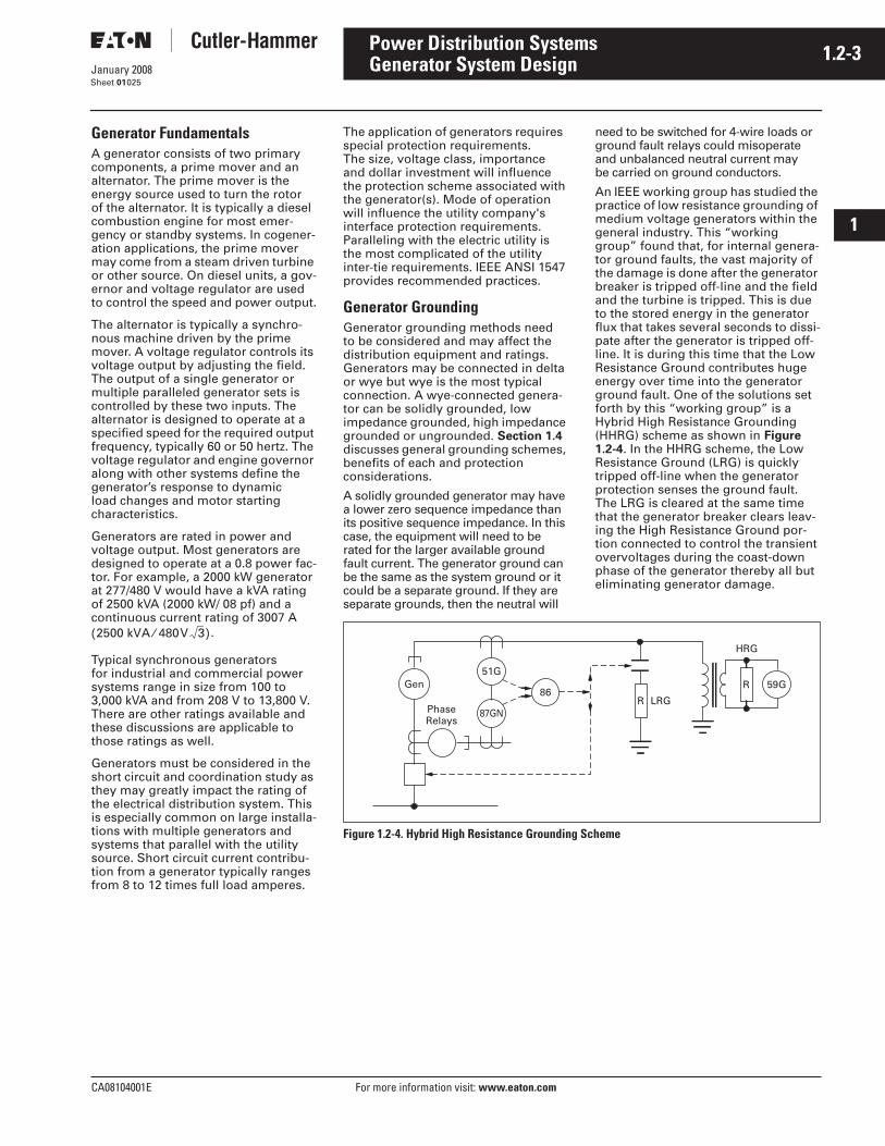
CA08104001E For more information visit: www.eaton.com
1.2-3January 2008
Power Distribution Systems
i
ii
1
2
3
4
5
6
7
8
9
10
11
12
13
14
15
16
17
18
19
20
21
Sheet 01
Generator System Design025
Generator FundamentalsA generator consists of two primary components, a prime mover and an alternator. The prime mover is the energy source used to turn the rotor of the alternator. It is typically a diesel combustion engine for most emer-gency or standby systems. In cogener-ation applications, the prime mover may come from a steam driven turbine or other source. On diesel units, a gov-ernor and voltage regulator are used to control the speed and power output.
The alternator is typically a synchro-nous machine driven by the prime mover. A voltage regulator controls its voltage output by adjusting the field. The output of a single generator or multiple paralleled generator sets is controlled by these two inputs. The alternator is designed to operate at a specified speed for the required output frequency, typically 60 or 50 hertz. The voltage regulator and engine governor along with other systems define the generator’s response to dynamic load changes and motor starting characteristics.
Generators are rated in power and voltage output. Most generators are designed to operate at a 0.8 power fac-tor. For example, a 2000 kW generator at 277/480 V would have a kVA rating of 2500 kVA (2000 kW/ 08 pf) and a continuous current rating of 3007 A
Typical synchronous generators for industrial and commercial power systems range in size from 100 to 3,000 kVA and from 208 V to 13,800 V. There are other ratings available and these discussions are applicable to those ratings as well.
Generators must be considered in the short circuit and coordination study as they may greatly impact the rating of the electrical distribution system. This is especially common on large installa-tions with multiple generators and systems that parallel with the utility source. Short circuit current contribu-tion from a generator typically ranges from 8 to 12 times full load amperes.
2500 kVA 480V 3⁄( ).
The application of generators requires special protection requirements. The size, voltage class, importance and dollar investment will influence the protection scheme associated with the generator(s). Mode of operation will influence the utility company's interface protection requirements. Paralleling with the electric utility is the most complicated of the utility inter-tie requirements. IEEE ANSI 1547 provides recommended practices.
Generator GroundingGenerator grounding methods need to be considered and may affect the distribution equipment and ratings. Generators may be connected in delta or wye but wye is the most typical connection. A wye-connected genera-tor can be solidly grounded, low impedance grounded, high impedance grounded or ungrounded. Section 1.4 discusses general grounding schemes, benefits of each and protection considerations.
A solidly grounded generator may have a lower zero sequence impedance than its positive sequence impedance. In this case, the equipment will need to be rated for the larger available ground fault current. The generator ground can be the same as the system ground or it could be a separate ground. If they are separate grounds, then the neutral will
need to be switched for 4-wire loads or ground fault relays could misoperate and unbalanced neutral current may be carried on ground conductors.
An IEEE working group has studied the practice of low resistance grounding of medium voltage generators within the general industry. This “working group” found that, for internal genera-tor ground faults, the vast majority of the damage is done after the generator breaker is tripped off-line and the field and the turbine is tripped. This is due to the stored energy in the generator flux that takes several seconds to dissi-pate after the generator is tripped off-line. It is during this time that the Low Resistance Ground contributes huge energy over time into the generator ground fault. One of the solutions set forth by this “working group” is a Hybrid High Resistance Grounding (HHRG) scheme as shown in Figure 1.2-4. In the HHRG scheme, the Low Resistance Ground (LRG) is quickly tripped off-line when the generator protection senses the ground fault. The LRG is cleared at the same time that the generator breaker clears leav-ing the High Resistance Ground por-tion connected to control the transient overvoltages during the coast-down phase of the generator thereby all but eliminating generator damage.
Figure 1.2-4. Hybrid High Resistance Grounding Scheme
Gen 59G51G
87GN
86
PhaseRelays
HRG
LRGR
R
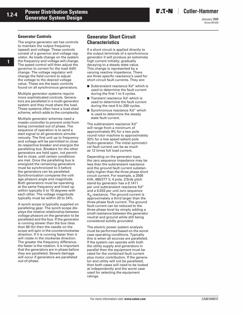
1.2-4
For more information visit: www.eaton.com CA08104001E
January 2008
Power Distribution Systems
i
ii
1
2
3
4
5
6
7
8
9
10
11
12
13
14
15
16
17
18
19
20
21
Sheet 01
Generator System Design026
Generator ControlsThe engine generator set has controls to maintain the output frequency (speed) and voltage. These controls consist of a governor and voltage reg-ulator. As loads change on the system the frequency and voltage will change. The speed control will then adjust the governor to correct for the load (kW) change. The voltage regulator will change the field current to adjust the voltage to the desired voltage value. These are the basic controls found on all synchronous generators.
Multiple generator systems require more sophisticated controls. Genera-tors are paralleled in a multi-generator system and they must share the load. These systems often have a load shed scheme, which adds to the complexity.
Multiple generator schemes need a master controller to prevent units from being connected out of phase. The sequence of operation is to send a start signal to all generators simulta-neously. The first unit up to frequency and voltage will be permitted to close its respective breaker and energize the paralleling bus. Breakers for the other generators are held open, not permit-ted to close, until certain conditions are met. Once the paralleling bus is energized the remaining generators must be synchronized to it before the generators can be paralleled. Synchronization compares the volt-age phasors angle and magnitude. Both generators must be operating at the same frequency and lined up within typically 5 to 10 degrees with each other. The voltage magnitude typically must be within 20 to 24%.
A synch-scope is typically supplied on paralleling gear. The synch-scope dis-plays the relative relationship between voltage phasors on the generator to be paralleled and the bus. If the generator is running slower than the bus (less than 60 Hz) then the needle on the scope will spin in the counterclockwise direction. If it is running faster then it will rotate in the clockwise direction. The greater the frequency difference, the faster is the rotation. It is important that the generators are in phase before they are paralleled. Severe damage will occur if generators are paralleled out-of-phase.
Generator Short Circuit CharacteristicsIf a short circuit is applied directly to the output terminals of a synchronous generator it will produce an extremely high current initially; gradually decaying to a steady state value. This change is represented by a varying reactive impedance. There are three specific reactance's used for short circuit fault currents. They are:
■ Subtransient reactance Xd” which is used to determine the fault current during the first 1 to 5 cycles.
■ Transient reactance Xd’ which is used to determine the fault current during the next 5 to 200 cycles.
■ Synchronous reactance Xd” which is used to determine the steady state fault current.
The subtransient reactance Xd” will range from a minimum of approximately 9% for a two pole round rotor machine to approximately 32% for a low speed salient pole hydro-generator. The initial symmetri-cal fault current can be as much as 12 times full load current.
Depending on the generator type, the zero sequence impedance may be less than the subtransient reactance and the ground fault current substan-tially higher than the three phase short circuit current. For example, a 2500 kVA, 480/277 V, 4 pole, 2/3rds pitch stand-by generator has a 0.1411 per unit subtransient reactance Xd” and a 0.033 per unit zero sequence Xo reactance. The ground current is approximately a third larger than the three-phase fault current. The ground fault current can be reduced to the three-phase level by simply adding a small reactance between the generator neutral and ground while still being considered solidly grounded.
The electric power system analysis must be performed based on the worst case operating conditions. Typically this is when all sources are paralleled. If the system can operate with both the utility supply and generators in parallel then the equipment must be rated for the combined fault current plus motor contribution. If the genera-tor and utility will not be paralleled, then both cases will need to be looked at independently and the worst case used for selecting the equipment ratings.
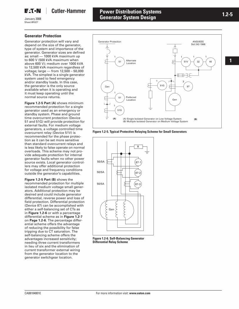
CA08104001E For more information visit: www.eaton.com
1.2-5January 2008
Power Distribution Systems
i
ii
1
2
3
4
5
6
7
8
9
10
11
12
13
14
15
16
17
18
19
20
21
Sheet 01
Generator System Design027
Generator ProtectionGenerator protection will vary and depend on the size of the generator, type of system and importance of the generator. Generator sizes are defined as: small — 1000 kVA maximum up to 600 V (500 kVA maximum when above 600 V); medium over 1000 kVA to 12,500 kVA maximum regardless of voltage; large — from 12,500 – 50,000 kVA. The simplest is a single generator system used to feed emergency and/or standby loads. In this case, the generator is the only source available when it is operating and it must keep operating until the normal source returns.
Figure 1.2-5 Part (A) shows minimum recommended protection for a single generator used as an emergency or standby system. Phase and ground time overcurrent protection (Device 51 and 51G) will provide protection for external faults. For medium voltage generators, a voltage controlled time overcurrent relay (Device 51V) is recommended for the phase protec-tion as it can be set more sensitive than standard overcurrent relays and is less likely to false operate on normal overloads. This scheme may not pro-vide adequate protection for internal generator faults when no other power source exists. Local generator control-lers may offer additional protection for voltage and frequency conditions outside the generator’s capabilities.
Figure 1.2-5 Part (B) shows the recommended protection for multiple isolated medium voltage small gener-ators. Additional protection may be desired and could include generator differential, reverse power and loss of field protection. Differential protection (Device 87) can be accomplished with either a self-balancing set of CTs as in Figure 1.2-6 or with a percentage differential scheme as in Figure 1.2-7 on Page 1.2-6. The percentage differ-ential scheme offers the advantage of reducing the possibility for false tripping due to CT saturation. The self-balancing scheme offers the advantages increased sensitivity; needing three current transformers in lieu of six and the elimination of current transformer external wiring from the generator location to the generator switchgear location.
Figure 1.2-5. Typical Protective Relaying Scheme for Small Generators
Figure 1.2-6. Self-Balancing Generator Differential Relay Scheme
51G
1
Preferred Location
51
51G
1
1
Gen
51
1
Alternate Location
1 1
51V 32 40
1
3
87
Gen
Generator Protection ANSI/IEEE Std 242-1986
(A) (B)(A) Single Isolated Generator on Low Voltage System(B) Multiple Isolated Generator on Medium Voltage System
87-1
87-3
87-2
50/5A
50/5A
50/5A
R
Gen
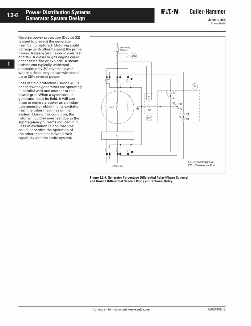
1.2-6
For more information visit: www.eaton.com CA08104001E
January 2008
Power Distribution Systems
i
ii
1
2
3
4
5
6
7
8
9
10
11
12
13
14
15
16
17
18
19
20
21
Sheet 01
Generator System Design028
Reverse power protection (Device 32) is used to prevent the generator from being motored. Motoring could damage (with other hazards) the prime mover. A steam turbine could overheat and fail. A diesel or gas engine could either catch fire or explode. A steam turbine can typically withstand approximately 3% reverse power where a diesel engine can withstand up to 25% reverse power.
Loss of field protection (Device 40) is needed when generators are operating in parallel with one another or the power grid. When a synchronous generator loses its field, it will con-tinue to generate power as an induc-tion generator obtaining its excitation from the other machines on the system. During this condition, the rotor will quickly overheat due to the slip frequency currents induced in it. Loss of excitation in one machine could jeopardize the operation of the other machines beyond their capability and the entire system.
Figure 1.2-7. Generator Percentage Differential Relay (Phase Scheme) and Ground Differential Scheme Using a Directional Relay
87
01 R1
02 R2
03 R3
R1
R2
R3
PC
OC
87G
Grounding Resistor
51G
To Main Bus
52
Gen
OC = Operating CoilPC = Permissive Coil
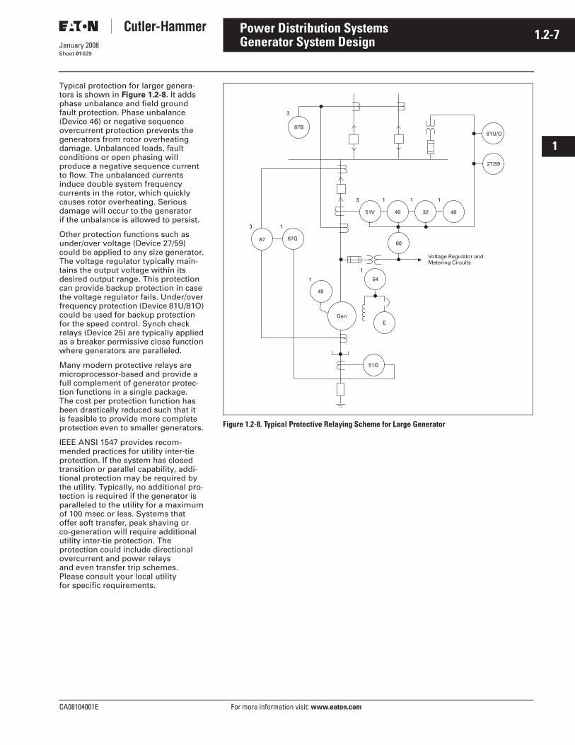
CA08104001E For more information visit: www.eaton.com
1.2-7January 2008
Power Distribution Systems
i
ii
1
2
3
4
5
6
7
8
9
10
11
12
13
14
15
16
17
18
19
20
21
Sheet 01
Generator System Design029
Typical protection for larger genera-tors is shown in Figure 1.2-8. It adds phase unbalance and field ground fault protection. Phase unbalance (Device 46) or negative sequence overcurrent protection prevents the generators from rotor overheating damage. Unbalanced loads, fault conditions or open phasing will produce a negative sequence current to flow. The unbalanced currents induce double system frequency currents in the rotor, which quickly causes rotor overheating. Serious damage will occur to the generatorif the unbalance is allowed to persist.
Other protection functions such as under/over voltage (Device 27/59) could be applied to any size generator. The voltage regulator typically main-tains the output voltage within its desired output range. This protection can provide backup protection in case the voltage regulator fails. Under/over frequency protection (Device 81U/81O) could be used for backup protection for the speed control. Synch check relays (Device 25) are typically applied as a breaker permissive close function where generators are paralleled.
Many modern protective relays are microprocessor-based and provide a full complement of generator protec-tion functions in a single package. The cost per protection function has been drastically reduced such that it is feasible to provide more complete protection even to smaller generators.
IEEE ANSI 1547 provides recom-mended practices for utility inter-tie protection. If the system has closed transition or parallel capability, addi-tional protection may be required by the utility. Typically, no additional pro-tection is required if the generator is paralleled to the utility for a maximum of 100 msec or less. Systems that offer soft transfer, peak shaving or co-generation will require additional utility inter-tie protection. The protection could include directional overcurrent and power relays and even transfer trip schemes.Please consult your local utility for specific requirements.
Figure 1.2-8. Typical Protective Relaying Scheme for Large Generator
3
87B
3
87
1
87G
1
49
Gen
1
64
E
60
46324051V
3
Voltage Regulator and Metering Circuits
51G
81U/O
27/59
111
1.2-8
For more information visit: www.eaton.com CA08104001E
January 2008
Power Distribution Systems
i
ii
1
2
3
4
5
6
7
8
9
10
11
12
13
14
15
16
17
18
19
20
21
Sheet 01
Generator System Design030
Generator Set Sizing and RatingsMany factors must be considered when determining the proper size or electrical rating of an electrical power generator set. The engine or prime mover is sized to provide the actual or real power in kW, as well as speed (frequency) control through the use of an engine governor. The generator is sized to supply the kVA needed at startup and during normal running operation and it also provides voltage control using a brushless exciter and voltage regulator. Together the engine and generator provide the energy necessary to supply electrical loads in many different applications encountered in today’s society.
The generator set must be able to supply the starting and running electrical load. It must be able to pick up and start all motor loads and low power factor loads, and recover with-out excessive voltage dip or extended recovery time. Non-linear loads like variable frequency drives, uninterrupt-ible power supply (UPS) systems and switching power supplies also require attention because the SCR switching causes voltage and current waveform distortion and harmonics. The har-monics generate additional heat in the generator windings and the generator may need to be upsized to accommo-date this. The type of fuel (diesel, natural gas, propane etc.) used is important as it is a factor in determin-ing generator set transient response. It is also necessary to determine the load factor or average power consumption of the generator set. This is typically defined as the load (kW) x time (hrs. while under that particular load) / total running time. When this load factor or average power is taken into consideration with peak demand requirements and the other operating parameters mentioned above, the overall electrical rating of the genset can be deter-mined. Other items to consider include the unique installation, ambient and site requirements of the project. These will help to determine the physical configuration of the overall system.
Typical rating definitions for diesel gensets are: standby, prime plus 10, continuous and load management (paralleled with or isolated from utility). Any diesel genset can have several electrical ratings depending on the number of hours of operation per year and the ratio of electrical load/genset rating when in operation. The same diesel genset can have a standby rating of 2000 kW at 0.8 power factor (pf) and a continuous rating of 1825 kW at 0.8 pf. The lower continu-ous rating is due to the additional hours of operation and higher load that the continuous genset must carry. These additional requirements put more stress on the engine and generator and therefore the rating is decreased to maintain longevity of the equipment.
Different generator set manufacturers use basically the same diesel genset electrical rating definitions and these are based on international diesel fuel stop power standards from organizations like ISO, DIN and others. A standby diesel genset rating is typically defined as supplying vary-ing electrical loads for the duration of a power outage with the load normally connected to utility, genset operating < 100 hours per year and no overload capability. A prime plus 10 rating is typically defined as supplying varying electrical loads for the duration of a power outage with the load normally connected to utility, genset operating ≤ 500 hours per year and overload capability of 10% above its rating for one hour out of twelve. A continu-ous rating is typically defined as supplying unvarying electrical loads (i.e., base loaded) for an unlimited time. The load management ratings apply to gensets in parallel operation with the utility or isolated/islanded from utility and these ratings vary in usability from < 200 hours per year to unlimited usage. Refer to generator set manufac-turers for further definitions on load management ratings, load factor or average power consumption, peak demand and how these ratings are typically applied. Even though there is some standardization of these ratings across the manufacturers, there also exists some uniqueness with regards to how each manufacturer applies their generator sets.
Electrical rating definitions for natural gas powered gensets are typically defined as standby or continuous with definitions similar to those mentioned above for diesels. Natural gas gensets recover more slowly than diesel gensets when subjected to block loads. Diesel engines have a much more direct path from the engine gov-ernor and fuel delivery system to the combustion chamber and this results in a very responsive engine-generator. A natural gas engine is challenged with air-fuel flow dynamics and a much more indirect path from the engine governor (throttle actuator) and fuel delivery system (natural gas pressure regulator, fuel valve and actuator, carburetor mixer, aftercooler, intake manifold) to the combustion chamber and this results in a less responsive engine-generator. Diesel gensets recover about twice as fast as natural gas gensets.
For the actual calculations involved for sizing a genset, there are readily accessible computer software pro-grams which are available on the genset manufacturer's Internet sites or from the manufacturer's dealers or distributors. These programs are used to quickly and accurately size generator sets for their application. The programs take into consideration the many different parameters dis-cussed above including the size and type of the electrical loads (resistive, inductive, SCR etc.), reduced voltage soft starting devices (RVSS), motor types, voltage, fuel type, site condi-tions, ambient conditions and other variables. The software will optimize the starting sequences of the motors for the least amount of voltage dip and determine the starting kVA needed from the genset. It also provides transient response data including voltage dip magnitude and recovery duration. If the transient response is unacceptable, then design changes can be considered including oversizing the generator to handle the additional kvar load, adding RVSS devices to reduce the inrush current, improving system power factor and other methods. The computer software programs are quite flexible in that they allow changes to the many different variables and parameters to achieve an optimum design. The software allows, for example, minimizing voltage dips or using paralleled gensets vs. a single genset.
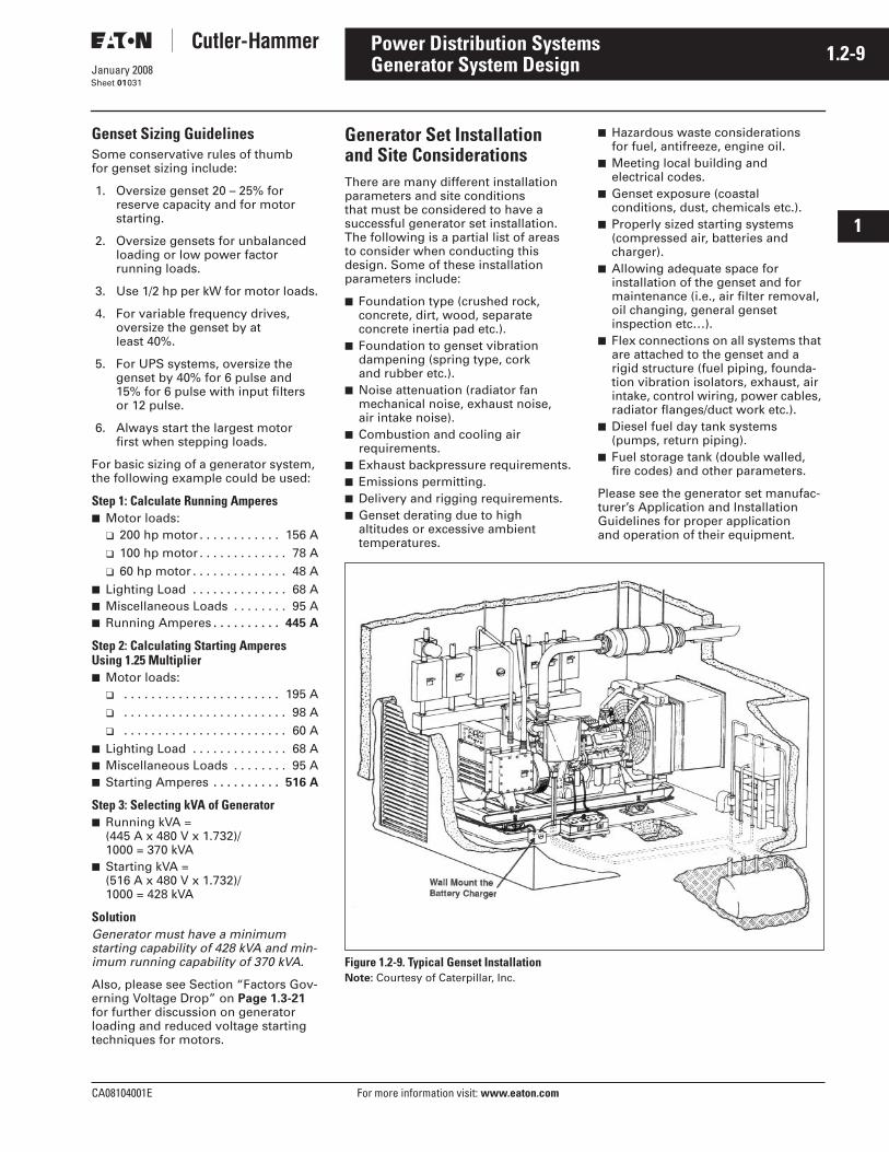
CA08104001E For more information visit: www.eaton.com
1.2-9January 2008
Power Distribution Systems
i
ii
1
2
3
4
5
6
7
8
9
10
11
12
13
14
15
16
17
18
19
20
21
Sheet 01
Generator System Design031
Genset Sizing GuidelinesSome conservative rules of thumb for genset sizing include:
1. Oversize genset 20 – 25% for reserve capacity and for motor starting.
2. Oversize gensets for unbalanced loading or low power factor running loads.
3. Use 1/2 hp per kW for motor loads.
4. For variable frequency drives, oversize the genset by at least 40%.
5. For UPS systems, oversize the genset by 40% for 6 pulse and 15% for 6 pulse with input filters or 12 pulse.
6. Always start the largest motor first when stepping loads.
For basic sizing of a generator system, the following example could be used:
Step 1: Calculate Running Amperes■ Motor loads:
❑ 200 hp motor . . . . . . . . . . . . 156 A❑ 100 hp motor . . . . . . . . . . . . . 78 A❑ 60 hp motor . . . . . . . . . . . . . . 48 A
■ Lighting Load . . . . . . . . . . . . . . 68 A■ Miscellaneous Loads . . . . . . . . 95 A■ Running Amperes . . . . . . . . . . 445 A
Step 2: Calculating Starting Amperes Using 1.25 Multiplier■ Motor loads:
❑ . . . . . . . . . . . . . . . . . . . . . . . 195 A❑ . . . . . . . . . . . . . . . . . . . . . . . . 98 A❑ . . . . . . . . . . . . . . . . . . . . . . . . 60 A
■ Lighting Load . . . . . . . . . . . . . . 68 A■ Miscellaneous Loads . . . . . . . . 95 A■ Starting Amperes . . . . . . . . . . 516 A
Step 3: Selecting kVA of Generator■ Running kVA =
(445 A x 480 V x 1.732)/1000 = 370 kVA
■ Starting kVA = (516 A x 480 V x 1.732)/1000 = 428 kVA
SolutionGenerator must have a minimum starting capability of 428 kVA and min-imum running capability of 370 kVA.
Also, please see Section “Factors Gov-erning Voltage Drop” on Page 1.3-21 for further discussion on generator loading and reduced voltage starting techniques for motors.
Generator Set Installation and Site ConsiderationsThere are many different installation parameters and site conditions that must be considered to have a successful generator set installation. The following is a partial list of areas to consider when conducting this design. Some of these installation parameters include:
■ Foundation type (crushed rock, concrete, dirt, wood, separate concrete inertia pad etc.).
■ Foundation to genset vibration dampening (spring type, cork and rubber etc.).
■ Noise attenuation (radiator fan mechanical noise, exhaust noise,air intake noise).
■ Combustion and cooling air requirements.
■ Exhaust backpressure requirements.■ Emissions permitting. ■ Delivery and rigging requirements.■ Genset derating due to high
altitudes or excessive ambient temperatures.
■ Hazardous waste considerations for fuel, antifreeze, engine oil.
■ Meeting local building and electrical codes.
■ Genset exposure (coastal conditions, dust, chemicals etc.).
■ Properly sized starting systems (compressed air, batteries and charger).
■ Allowing adequate space for installation of the genset and for maintenance (i.e., air filter removal, oil changing, general genset inspection etc…).
■ Flex connections on all systems that are attached to the genset and a rigid structure (fuel piping, founda-tion vibration isolators, exhaust, air intake, control wiring, power cables, radiator flanges/duct work etc.).
■ Diesel fuel day tank systems (pumps, return piping).
■ Fuel storage tank (double walled, fire codes) and other parameters.
Please see the generator set manufac-turer’s Application and Installation Guidelines for proper application and operation of their equipment.
Figure 1.2-9. Typical Genset InstallationNote: Courtesy of Caterpillar, Inc.
1.2-10
For more information visit: www.eaton.com CA08104001E
January 2008
Power Distribution Systems
i
ii
1
2
3
4
5
6
7
8
9
10
11
12
13
14
15
16
17
18
19
20
21
Sheet 01032
This page intentionally left blank.
CA08104001E For more information visit: www.eaton.com
1.3-1January 2008
Power Distribution Systems
i
ii
1
2
3
4
5
6
7
8
9
10
11
12
13
14
15
16
17
18
19
20
21
Sheet 01
System Analysis033
Systems AnalysisA major consideration in the design of a distribution system is to ensure that it provides the required quality of service to the various loads. This includes serving each load under normal conditions and, under abnormal conditions, providing the desired protection to service and system apparatus so that interruptions of service are minimized consistent with good economic and mechanical design.
Under normal conditions, the impor-tant technical factors include voltage profile, losses, load flow, effects of motor starting, service continuity and reliability. The prime considerations under faulted conditions are apparatus protection, fault isolation and service continuity. During the system prelimi-nary planning stage, before selection of the distribution apparatus, several distribution systems should be analyzed and evaluated including both economic and technical factors. During this stage if system size or complexity warrant, it may be appropriate to provide a thorough review of each system under both normal and abnormal conditions.
The principal types of computer programs utilized to provide system studies include:
■ Short circuit — identify 3-phase and line-to-ground fault currents and system impedances.
■ Arc flash — calculates arc flash energy levels which lead to the selection of personal protective equipment (PPE).
■ Circuit breaker duty — identify asymmetrical fault current based on X/R ratio.
■ Protective device coordination — determine characteristics and set-tings of medium voltage protective relays and fuses, and entire low voltage circuit breaker and fuse coordination.
■ Load flow — simulate normal load conditions of system voltages, power factor, line and transformer loadings.
■ Motor starting — identify system voltages, motor terminal voltage, motor accelerating torque, and motor accelerating time when starting large motors.
Short circuit calculations define momentary and steady-state fault currents for LV and MV breaker and fuse duty and bus bracings at any selected location in the system and also determine the effect on the system after removal of utility power due to breaker operation or scheduled power outages. Computer software programs can identify the fault current at any bus, in every line or source connected to the faulted bus, or to it and every adjacent bus, or to it and every bus which is one and two buses away, or currents in every line or source in the system. The results of these calculations permit optimizing service to the loads while properly applying distribution apparatus within their intended limits.
The following additional studies should be considered depending upon the type and complexity of the distribution system, the type of facility and the type of loads to be connected to the system:
■ Harmonic Analysis■ Transient Stability■ Insulation Coordination■ Grounding Study■ Switching Transient
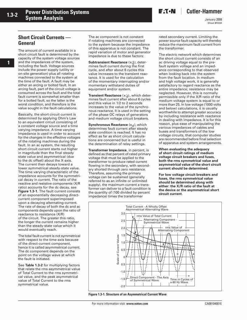
1.3-2
For more information visit: www.eaton.com CA08104001E
January 2008
Power Distribution Systems
i
ii
1
2
3
4
5
6
7
8
9
10
11
12
13
14
15
16
17
18
19
20
21
Sheet 01
System Analysis034
Short Circuit Currents — GeneralThe amount of current available in a short circuit fault is determined by the capacity of the system voltage sources and the impedances of the system, including the fault. Voltage sources include the power supply (utility or on-site generation) plus all rotating machines connected to the system at the time of the fault. A fault may be either an arcing or bolted fault. In an arcing fault, part of the circuit voltage is consumed across the fault and the total fault current is somewhat smaller than for a bolted fault, so the latter is the worst condition, and therefore is the value sought in the fault calculations.
Basically, the short circuit current is determined by applying Ohm’s Law to an equivalent circuit consisting of a constant voltage source and a time varying impedance. A time varying impedance is used in order to account for the changes in the effective voltages of the rotating machines during the fault. In an ac system, the resulting short circuit current starts out higher in magnitude than the final steady state value and asymmetrical (due to the dc offset) about the X-axis. The current then decays toward a lower symmetrical steady-state value. The time varying characteristic of the impedance accounts for the symmetri-cal decay in current. The ratio of the reactive and resistive components (X/R ratio) accounts for the dc decay, see Figure 1.3-1. The fault current consists of an exponentially decreasing direct-current component superimposed upon a decaying alternating-current. The rate of decay of both the dc and ac components depends upon the ratio of reactance to resistance (X/R) of the circuit. The greater this ratio, the longer the current remains higher than the steady-state value which it would eventually reach.
The total fault current is not symmetrical with respect to the time-axis because of the direct-current component, hence it is called asymmetrical current. The dc component depends on the point on the voltage wave at which the fault is initiated.
See Table 1.3-2 for multiplying factors that relate the rms asymmetrical value of Total Current to the rms symmetri-cal value, and the peak asymmetrical value of Total Current to the rms symmetrical value.
The ac component is not constant if rotating machines are connected to the system because the impedance of this apparatus is not constant. The rapid variation of motor and generator impedance is due to these factors:
Subtransient Reactance (x "d), deter-mines fault current during the first cycle, and after about 6 cycles this value increases to the transient reac-tance. It is used for the calculation of the momentary interrupting and/or momentary withstand duties of equipment and/or system.
Transient Reactance (x 'd), which deter-mines fault current after about 6 cycles and this value in 1/2 to 2 seconds increases to the value of the synchro-nous reactance. It is used in the setting of the phase OC relays of generators and medium voltage circuit breakers.
Synchronous Reactance (xd), which determines fault current after steady state condition is reached. It has no effect as far as short circuit calcula-tions are concerned but is useful in the determination of relay settings.
Transformer Impedance, in percent, is defined as that percent of rated primary voltage that must be applied to the transformer to produce rated current flowing in the secondary, with second-ary shorted through zero resistance. Therefore, assuming the primary voltage can be sustained (generally referred to as an infinite or unlimited supply), the maximum current a trans-former can deliver to a fault condition is the quantity of (100 divided by percent impedance) times the transformer
rated secondary current. Limiting the power source fault capacity will thereby reduce the maximum fault current from the transformer.
The electric network which determines the short circuit current consists of an ac driving voltage equal to the pre-fault system voltage and an imped-ance corresponding to that observed when looking back into the system from the fault location. In medium and high voltage work, it is generally satisfactory to regard reactance as the entire impedance; resistance may be neglected. However, this is normally permissible only if the X/R ratio of the medium voltage system is equal to or more than 25. In low voltage (1000 volts and below) calculations, it is usually worthwhile to attempt greater accuracy by including resistance with reactance in dealing with impedance. It is for this reason, plus ease of manipulating the various impedances of cables and buses and transformers of the low voltage circuits, that computer studies are recommended before final selection of apparatus and system arrangements.
When evaluating the adequacy of short circuit ratings of medium voltage circuit breakers and fuses, both the rms symmetrical value and asymmetrical value of the short circuit current should be determined.
For low voltage circuit breakers and fuses, the rms symmetrical value should be determined along with either: the X/R ratio of the fault at the device or the asymmetrical short circuit current.
Figure 1.3-1. Structure of an Asymmetrical Current Wave
3.0
2.5
2.0
1.5
1.0
0.5
0
0.5
-1.0
-1.5
-2.0
Total Current - A Wholly OffsetAsymmetrical Alternating Wave
rms Value of Total Current Alternating Component - Symmetrical Wave
rms Value ofAlternating Component
Direct Component - The Axisof Symmetrical Wave Time in Cycles of
a 60 Hz Wave
1 2 3 4
Sca
le o
f C
ure
nt
Valu
es
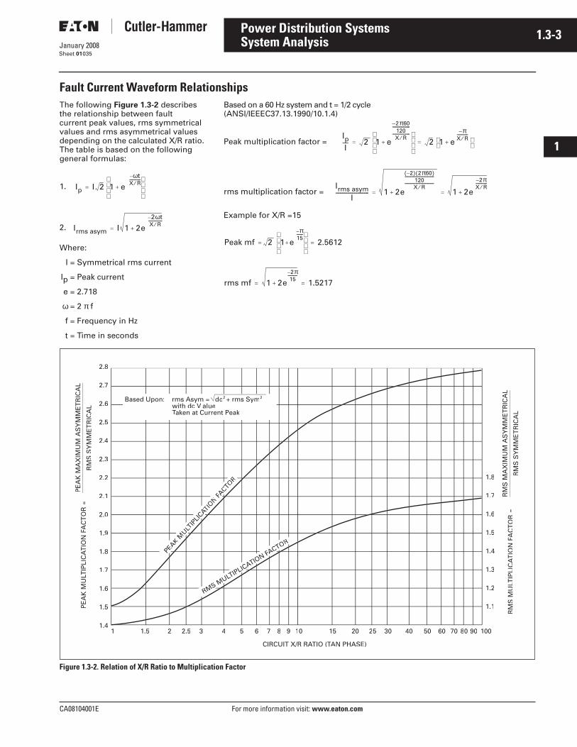
CA08104001E For more information visit: www.eaton.com
1.3-3January 2008
Power Distribution Systems
i
ii
1
2
3
4
5
6
7
8
9
10
11
12
13
14
15
16
17
18
19
20
21
Sheet 01
System Analysis035
Fault Current Waveform RelationshipsThe following Figure 1.3-2 describes the relationship between fault current peak values, rms symmetrical values and rms asymmetrical values depending on the calculated X/R ratio. The table is based on the following general formulas:
1.
2.
Where:
I = Symmetrical rms current
Ip = Peak current
e = 2.718
ω = 2 π f
f = Frequency in Hz
t = Time in seconds
Based on a 60 Hz system and t = 1/2 cycle(ANSI/IEEEC37.13.1990/10.1.4)
Peak multiplication factor =
rms multiplication factor =
Example for X/R =15
Figure 1.3-2. Relation of X/R Ratio to Multiplication Factor
Ip I 2 1 eωt–
X R⁄------------
+
=
Irms asym I 1 2e2ωt–
X R⁄---------------
+=
IpI
----- 2 1 e
2π60–120
----------------
X R⁄----------------
+
2 1 eπ–
X R⁄----------
+ = =
Irms asymI
------------------------------ 1 2e
2–( ) 2π60( )120
-------------------------------
X R⁄-------------------------------
+ 1 2e
2π–X R⁄------------
+= =
Peak mf 2 1 e
π–15-------
+
2.5612= =
rms mf 1 2e2π–15
----------
+ 1.5217= =
2.8
2.7
2.6
2.5
2.4
2.3
2.2
2.1
2.0
1.9
1.8
1.7
1.6
1.5
1.41.51 21.5 2.5 3 4 5 6 7 8 9 10 15 20 25 30 40 50 60 70 80 90 100
1.8
1.7
1.6
1.5
1.4
1.3
1.2
1.1
PEAK
MULT
IPLI
CATIAAON
FACTO
FF
R
RMS MULTIPLICA
LL
TION F
AA
ACTOFF
R
CIRCUIT X/R RATIO (TAA AN PHASETT )
Based Upon: rms Asym = dc2 + rms Sym2
with dc V eTaken at Current PeakTT
RM
S M
ULT
IPLI
CA
LLT
ION
FAA
AC
TO
R
FF=
RM
S M
AX
IMU
M A
SY
MM
ET
RIC
AL
RM
S S
YM
ME
TR
ICA
L
PE
AK
MU
LTIP
LIC
ALL
TIO
N F
AAA
CT
OR
FF
=P
EA
K M
AX
IMU
M A
SY
MM
ET
RIC
AL
RM
S S
YM
ME
TR
ICA
L
1.3-4
For more information visit: www.eaton.com CA08104001E
January 2008
Power Distribution Systems
i
ii
1
2
3
4
5
6
7
8
9
10
11
12
13
14
15
16
17
18
19
20
21
Sheet 01
System Analysis036
Fault Current CalculationsThe calculation of asymmetrical cur-rents is a laborious procedure since the degree of asymmetry is not the same on all three phases. It is common practice for medium voltage systems, to calculate the rms symmetrical fault current, with the assumption being made that the dc component has decayed to zero, and then apply a multiplying factor to obtain the first half-cycle rms asymmetrical current, which is called the “momentary cur-rent.” For medium voltage systems (defined by IEEE as greater than 1000 volts up to 69,000 volts) the multiply-ing factor is established by NEMA� and ANSI standards depending upon the operating speed of the breaker. For low voltage systems, short circuit study software usually calculates the symmetrical fault current and the faulted system X/R ratio using ANSI guidelines. If the X/R ratio is within the standard, and the breaker interrupting current is under the symmetrical fault value, the breaker is properly rated. If the X/R ratio is higher than ANSI stan-dards, the study applies a multiplying factor to the symmetrical calculated value (based on the X/R value of the system fault) and compares that value to the breaker symmetrical value to assess if it is properly rated. In the past, especially using manual calculations, a multiplying factor of 1.17 (based on the use of an X/R ratio of 6.6 represent-ing a source short circuit power factor of 15%) was used to calculate the asymmetrical current. These values take into account that medium voltage breakers are rated on maximum asym-metry and low voltage breakers are rated average asymmetry.
To determine the motor contribution during the first half-cycle fault current, when individual motor horsepower load is known, the subtransient reac-tances found in the IEEE Red should be used in the calculations. When the system motor load is unknown, the following assumptions generally are made:
Induction Motors — Use 4.0 times motor full load current (impedance value of 25%).
Note: For motors fed through adjustable frequency drives or solid-state soft starters, there is no contribution to fault current, unless 1) they have an internal run contactor or2) they have a bypass contactor.
Synchronous Motors — Use 5.0 times motor full load current (impedance value of 20%).
When the motor load is not known, the following assumptions generally are made:
208Y/120 V Systems■ Assume 50% lighting and 50%
motor load.
or
■ Assume motor feedback contribu-tion of twice full load current of transformer.
or
240/480/600 V 3-Phase, 3-Wire or 4-Wire Systems■ Assume 100% motor load.
or
■ Assume motors 25% synchronous and 75% induction.
or
■ Assume motor feedback contribu-tion of four times full load current of transformer.
480Y/277 V Systems in Commercial Buildings■ Assume 50% induction motor load.
or
■ Assume motor feedback contribu-tion of two times full load current of transformer or source.
Medium Voltage MotorsIf known, use actual values otherwise use the values indicated for the same type of motor.
Calculation MethodsThe following pages describe various methods of calculating short circuit currents for both medium and low voltage systems. A summary of the types of methods and types of calcula-tions is as follows:
■ Medium Voltage Switchgear — exact method . . . . . . . . . Page 1.3-5
■ Medium Voltage Switchgear — quick check table . . . . . . Page 1.3-7
■ Medium Voltage Switchgear Example 1 — Verify ratings of breakers . . . . . . . . . . . . . Page 1.3-8
■ Medium Voltage Switchgear Example 2 — Verify ratings of breakers with rotating loads . . . . . . . . . . . . . . . . Page 1.3-9
■ Medium Voltage Switchgear Example 3 — Verify ratings of breakers with generators . . . . . . . . . . . Page 1.3-10
■ Medium Voltage Fuses — exact method . . . . . . . . . Page 1.3-11
■ Power Breakers — Asymmetry derating factors . . . . . . . Page 1.3-11
■ Molded Case Breakers — asymmetry derating factors . . . . . . . Page 1.3-12
■ Short Circuit Calculations — Short cut method for a system . . . . . . . . . . . . . Page 1.3-13
■ Short Circuit Calculations — Short cut method for end of cable . . . . . . . . . . Page 1.3-15
■ Short Circuit Calculations — Short cut method for end of cable chart method . . . . Page 1.3-16
■ Short Circuit Currents — Chart of transformers 300 to 3750 kVA . . . . . . . . . . . . . Page 1.5-9
CA08104001E For more information visit: www.eaton.com
1.3-5January 2008
Power Distribution Systems
i
ii
1
2
3
4
5
6
7
8
9
10
11
12
13
14
15
16
17
18
19
20
21
Sheet 01
System Analysis037
Fault Current Calculations for Specific Equipment — Exact MethodThe purpose of the fault current calcu-lations is to determine the fault current at the location of a circuit breaker, fuse or other fault interrupting device in order to select a device adequate for the calculated fault current or to check the thermal and momentary ratings of non-interrupting devices. When the devices to be used are ANSI-rated devices, the fault current must be calculated and the device selected as per ANSI standards.
The calculation of available fault current and system X/R rating is also utilized to verify adequate bus bar bracing and momentary withstand ratings of devices such as contactors.
Medium Voltage VCP-W Metal-Clad SwitchgearThe applicable ANSI Standards C37 is the latest applicable edition. The following is a review of the meaning of the ratings. (See Section 5.)
The Rated Maximum VoltageThis designates the upper limit of design and operation of a circuit breaker. For example, a circuit breaker with a 4.76 kV rated maximum voltage cannot be used in a 4.8 kV system.
K-Rated Voltage FactorThe rated voltage divided by this factor determines the system kV a breaker can be applied up to the short circuit kVA rating calculated by the formula
Note: Interrupting capabilities of some of today’s vacuum breakers may have K = 1, whereby the interrupting current is constant across its entire operating range.
Rated Short Circuit CurrentThis is the symmetrical rms value of current that the breaker can interrupt at rated maximum voltage. It should be noted that the product x 4.76 x 29,000 = 239,092 kVA is less than the nominal 250,000 kVA listed. This rating (29,000 amperes) is also the base quantity that all the “related” capabilities are referred to.
Maximum Symmetrical Interrupting CapabilityThis is expressed in rms symmetrical amperes or kiloamperes and is K x I rated; 29,000 x 1.24 = 35,960 rounded to 36 kA.
This is the rms symmetrical current that the breaker can interrupt down to
3 Rated SC Current× Rated Max. Voltage×
3
a voltage = maximum rated voltage divided by K (for example, 4.76/1.24 = 3.85). If this breaker is applied in a system rated at 2.4 kV the calculated fault current must be less than 36 kA.
For example, consider the following case:
Assume a 12.47 kV system with 20,000 amperes symmetrical available. In order to determine if an Eaton’s Cutler-Hammer� Type 150 VCP-W 500 vacuum breaker is suitable for this application, check the following:
From Table 5.4-1 in Section 5 under column “Rated Maximum Voltage” V = 15 kV, under column “Rated short circuit Current” I = 18 kA, “Rated Voltage Range Factor” K = 1.3.
Test 1 for V/Vo x I or 15 kV/12.47 kV x 18 kA = 21.65; also check K x I (which is shown in the column headed “Maximum Symmetrical Interrupting Capability”) or 1.3 x 18 kA = 23.4 kA. Since both of these numbers are
greater than the available system fault current of 20,000 amperes, the breaker is acceptable (assumes the breaker’s momentary and fault close rating is also acceptable).
Note: If the system available fault current were 22,000 amperes symmetrical, this breaker could not be utilized even though the “Maximum Symmetrical Interrupting Capability” is greater than 22,000 since Test 1 calculation is not satisfied.
For approximate calculations, Table 1.3-1 provides typical values of % reactance (X) and X/R values for various rotating equipment and transformers. For sim-plification purposes, the transformer impedance (Z) has been assumed to be primarily reactance (X). In addition, the resistance (R) for these simplified cal-culations has been ignored. For detailed calculations, the values from the IEEE Red Book Standard 141, for rotating machines, and ANSI C57 and/or C37 for transformers should be utilized.
Table 1.3-1. Reactance X
Table 1.3-2. Typical System X/R Ratio Range (for Estimating Purposes)
System Component
Reactance X Used for Typical Values and Range on Component BaseShort Circuit
DutyClose and Latch(Momentary) % Reactance X/R Ratio
2-Pole Turbo Generator4-Pole Turbo Generator
XX
XX
9 (7 – 14)15 (12 – 17)
80 (40 – 120)80 (40 – 120)
Hydro Generator with Damper Wedgesand Synchronous Condensers
X X 20 (13 – 32) 30 (10 – 60)
Hydro Generator without Damper Windings .75X .75X 16 (16 – 50) 30 (10 – 60)
All Synchronous Motors 1.5X 1.0X 20 (13 – 35) 30 (10 – 60)
Ind. Motors Above 1000 hp, 1800 Rpmand Above 250 hp, 3600 Rpm
1.5X 1.0X 17 (15 – 25) 30 (15 – 40)
All Other Induction Motors 50 hp and Above 3.0X 1.2X 17 (15 – 25) 15 (2 – 40)
Ind. Motors Below 50 hp andAll Single-Phase Motors
Neglect Neglect — —
Distribution System from RemoteTransformers
X X As Specifiedor Calculated
15 (5 – 15)
Current Limiting Reactors X X As Specifiedor Calculated
80 (40 – 120)
TransformersOA to 10 MVA, 69 kV X X 8.0 18 (7 – 24)
OA to 10 MVA, above 69 kV X X 8.0 to 10.5Depends on Primary Windings BIL Rating
18 (7 – 24)
FOA 12 to 30 MVA X X 20 (7 – 30)
FOA 40 to 100 MVA X X 38 (32 – 44)
Type of Circuit X/R Range
Remote generation through other types of circuits such as transformers rated 10 MVA or smaller for each 3-phase bank, transmission lines, distribution feeders, etc.
15 or less
Remote generation connected through transformer rated 10 MVA to 100 MVA for each 3-phase bank, where the transformers provide 90 percent or more of the total equivalent impedance to the fault point.
15 – 40
Remote generation connected through transformers rated 100 MVA or largerfor each 3-phase bank where the transformers provide 90 percent or more of the total equivalent impedance to the fault point.
30 – 50
Synchronous machines connected through transformers rated 25 to 100 MVA for each 3-phase bank.
30 – 50
Synchronous machines connected through transformers rated 100 MVA and larger. 40 – 60
Synchronous machines connected directly to the bus or through reactors. 40 – 120
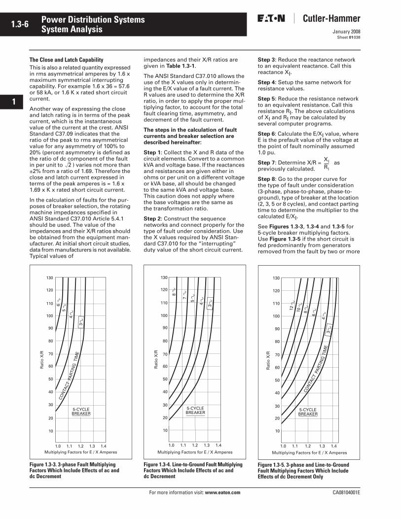
1.3-6
For more information visit: www.eaton.com CA08104001E
January 2008
Power Distribution Systems
i
ii
1
2
3
4
5
6
7
8
9
10
11
12
13
14
15
16
17
18
19
20
21
Sheet 01
System Analysis038
The Close and Latch CapabilityThis is also a related quantity expressed in rms asymmetrical amperes by 1.6 x maximum symmetrical interrupting capability. For example 1.6 x 36 = 57.6 or 58 kA, or 1.6 K x rated short circuit current.
Another way of expressing the close and latch rating is in terms of the peak current, which is the instantaneous value of the current at the crest. ANSI Standard C37.09 indicates that the ratio of the peak to rms asymmetrical value for any asymmetry of 100% to 20% (percent asymmetry is defined as the ratio of dc component of the fault in per unit to ) varies not more than ±2% from a ratio of 1.69. Therefore the close and latch current expressed in terms of the peak amperes is = 1.6 x 1.69 x K x rated short circuit current.
In the calculation of faults for the pur-poses of breaker selection, the rotating machine impedances specified in ANSI Standard C37.010 Article 5.4.1 should be used. The value of the impedances and their X/R ratios should be obtained from the equipment man-ufacturer. At initial short circuit studies, data from manufacturers is not available. Typical values of
Figure 1.3-3. 3-phase Fault Multiplying Factors Which Include Effects of ac and dc Decrement
impedances and their X/R ratios are given in Table 1.3-1.
The ANSI Standard C37.010 allows the use of the X values only in determin-ing the E/X value of a fault current. The R values are used to determine the X/R ratio, in order to apply the proper mul-tiplying factor, to account for the total fault clearing time, asymmetry, and decrement of the fault current.
The steps in the calculation of fault currents and breaker selection are described hereinafter:
Step 1: Collect the X and R data of the circuit elements. Convert to a common kVA and voltage base. If the reactances and resistances are given either in ohms or per unit on a different voltage or kVA base, all should be changed to the same kVA and voltage base. This caution does not apply where the base voltages are the same as the transformation ratio.
Step 2: Construct the sequence networks and connect properly for the type of fault under consideration. Use the X values required by ANSI Stan-dard C37.010 for the “interrupting” duty value of the short circuit current.
Figure 1.3-4. Line-to-Ground Fault Multiplying Factors Which Include Effects of ac and dc Decrement
Step 3: Reduce the reactance network to an equivalent reactance. Call this reactance XI.
Step 4: Setup the same network for resistance values.
Step 5: Reduce the resistance network to an equivalent resistance. Call this resistance RI. The above calculations of XI and RI may be calculated by several computer programs.
Step 6: Calculate the E/XI value, where E is the prefault value of the voltage at the point of fault nominally assumed 1.0 pu.
Step 7: Determine X/R = as previously calculated.
Step 8: Go to the proper curve for the type of fault under consideration (3-phase, phase-to-phase, phase-to-ground), type of breaker at the location (2, 3, 5 or 8 cycles), and contact parting time to determine the multiplier to the calculated E/XI.
See Figures 1.3-3, 1.3-4 and 1.3-5 for 5-cycle breaker multiplying factors. Use Figure 1.3-5 if the short circuit is fed predominantly from generators removed from the fault by two or more
Figure 1.3-5. 3-phase and Line-to-Ground Fault Multiplying Factors Which Include Effects of dc Decrement Only
2
65
4
CO
NTA
CT
PAR
TIN
GTI
ME
3
5-CYCLEBREAKER
1.0 1.1 1.2 1.3 1.4Multiplying Factors for E / X Amperes
Rat
io X
/R
130
120
110
100
90
80
70
60
50
40
30
20
10
7
8
5-CYCLEBREAKER
1.0 1.1 1.2 1.3 1.4
Multiplying Factors for E / X Amperes
34
5
Rat
io X
/R
130
120
110
100
90
80
70
60
50
40
30
20
10
XI
RI------
4
5-CYCLEBREAKER
1.0 1.1 1.2 1.3 1.4
Multiplying Factors for E / X Amperes
6
81012
CON
TACT
PART
ING
TIM
E3
Rat
io X
/R
130
120
110
100
90
80
70
60
50
40
30
20
10
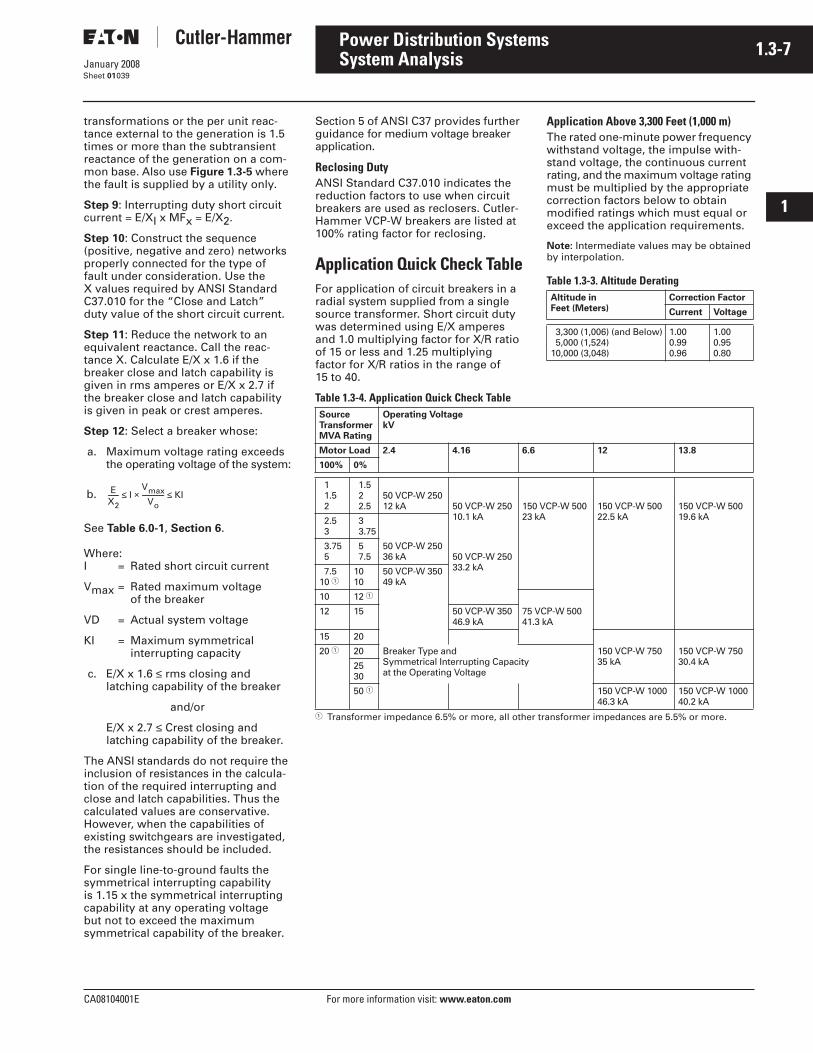
CA08104001E For more information visit: www.eaton.com
1.3-7January 2008
Power Distribution Systems
i
ii
1
2
3
4
5
6
7
8
9
10
11
12
13
14
15
16
17
18
19
20
21
Sheet 01
System Analysis039
transformations or the per unit reac-tance external to the generation is 1.5 times or more than the subtransient reactance of the generation on a com-mon base. Also use Figure 1.3-5 where the fault is supplied by a utility only.
Step 9: Interrupting duty short circuit current = E/XI x MFx = E/X2.
Step 10: Construct the sequence (positive, negative and zero) networks properly connected for the type of fault under consideration. Use the X values required by ANSI Standard C37.010 for the “Close and Latch” duty value of the short circuit current.
Step 11: Reduce the network to an equivalent reactance. Call the reac-tance X. Calculate E/X x 1.6 if the breaker close and latch capability is given in rms amperes or E/X x 2.7 if the breaker close and latch capability is given in peak or crest amperes.
Step 12: Select a breaker whose:
a. Maximum voltage rating exceeds the operating voltage of the system:
b.
See Table 6.0-1, Section 6.
Where:I = Rated short circuit current
Vmax = Rated maximum voltage of the breaker
VD = Actual system voltage
KI = Maximum symmetrical interrupting capacity
c. E/X x 1.6 ≤ rms closing and latching capability of the breaker
and/or
E/X x 2.7 ≤ Crest closing and latching capability of the breaker.
The ANSI standards do not require the inclusion of resistances in the calcula-tion of the required interrupting and close and latch capabilities. Thus the calculated values are conservative. However, when the capabilities of existing switchgears are investigated, the resistances should be included.
For single line-to-ground faults the symmetrical interrupting capability is 1.15 x the symmetrical interrupting capability at any operating voltage but not to exceed the maximum symmetrical capability of the breaker.
EX2------- I
VmaxVo
-------------- KI≤×≤
Section 5 of ANSI C37 provides further guidance for medium voltage breaker application.
Reclosing DutyANSI Standard C37.010 indicates the reduction factors to use when circuit breakers are used as reclosers. Cutler-Hammer VCP-W breakers are listed at 100% rating factor for reclosing.
Application Quick Check TableFor application of circuit breakers in a radial system supplied from a single source transformer. Short circuit duty was determined using E/X amperes and 1.0 multiplying factor for X/R ratio of 15 or less and 1.25 multiplying factor for X/R ratios in the range of 15 to 40.
Application Above 3,300 Feet (1,000 m)The rated one-minute power frequency withstand voltage, the impulse with-stand voltage, the continuous current rating, and the maximum voltage rating must be multiplied by the appropriate correction factors below to obtain modified ratings which must equal or exceed the application requirements.
Note: Intermediate values may be obtained by interpolation.
Table 1.3-3. Altitude Derating
Table 1.3-4. Application Quick Check Table
� Transformer impedance 6.5% or more, all other transformer impedances are 5.5% or more.
Altitude inFeet (Meters)
Correction Factor
Current Voltage
3,300 (1,006) (and Below) 5,000 (1,524)10,000 (3,048)
1.000.990.96
1.000.950.80
SourceTransformerMVA Rating
Operating Voltage kV
Motor Load 2.4 4.16 6.6 12 13.8
100% 0%
1 1.5 2
1.5 2 2.5
50 VCP-W 25012 kA 50 VCP-W 250
10.1 kA150 VCP-W 50023 kA
150 VCP-W 50022.5 kA
150 VCP-W 50019.6 kA 2.5
3 3 3.75
3.75 5
5 7.5
50 VCP-W 25036 kA 50 VCP-W 250
33.2 kA 7.510 �
1010
50 VCP-W 35049 kA
10 12 �
12 15 50 VCP-W 35046.9 kA
75 VCP-W 50041.3 kA
15 20
20 � 20 Breaker Type andSymmetrical Interrupting Capacityat the Operating Voltage
150 VCP-W 75035 kA
150 VCP-W 75030.4 kA25
30
50 � 150 VCP-W 100046.3 kA
150 VCP-W 100040.2 kA
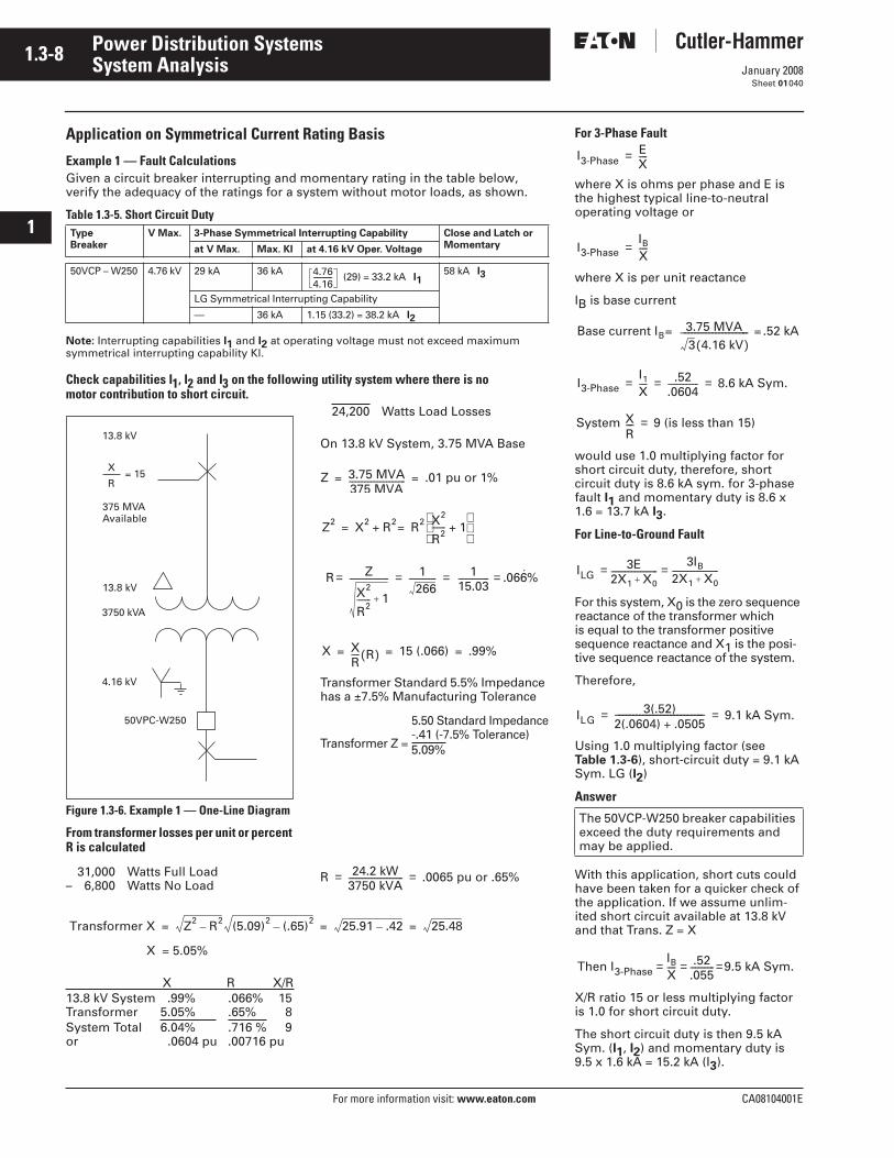
1.3-8
For more information visit: www.eaton.com CA08104001E
January 2008
Power Distribution Systems
i
ii
1
2
3
4
5
6
7
8
9
10
11
12
13
14
15
16
17
18
19
20
21
Sheet 01
System Analysis040
Application on Symmetrical Current Rating Basis
Example 1 — Fault CalculationsGiven a circuit breaker interrupting and momentary rating in the table below, verify the adequacy of the ratings for a system without motor loads, as shown.
Table 1.3-5. Short Circuit Duty
Note: Interrupting capabilities I1 and I2 at operating voltage must not exceed maximum symmetrical interrupting capability Kl.
Check capabilities I1, I2 and I3 on the following utility system where there is no motor contribution to short circuit.
Figure 1.3-6. Example 1 — One-Line Diagram
From transformer losses per unit or percent R is calculated
31,000 Watts Full Load– 6,800 Watts No Load
24,200 Watts Load Losses
On 13.8 kV System, 3.75 MVA Base
Transformer Standard 5.5% Impedance has a ±7.5% Manufacturing Tolerance
5.50 Standard Impedance-.41 (-7.5% Tolerance)
Transformer Z = 5.09%
X = 5.05%
X R X/R13.8 kV System .99% .066% 15Transformer 5.05% .65% 8System Total 6.04% .716 % 9or .0604 pu .00716 pu
TypeBreaker
V Max. 3-Phase Symmetrical Interrupting Capability Close and Latch orMomentaryat V Max. Max. KI at 4.16 kV Oper. Voltage
50VCP – W250 4.76 kV 29 kA 36 kA (29) = 33.2 kA I158 kA I3
LG Symmetrical Interrupting Capability
— 36 kA 1.15 (33.2) = 38.2 kA I2
4.764.16-----------
13.8 kV
375 MVAAvailable
13.8 kV
3750 kVA
4.16 kV
50VPC-W250
= 15X
R Z 3.75 MVA375 MVA--------------------------------- .01 pu or 1%= =
Z2 X2 R2 R2 X2
R2-------- 1+
=+=
R Z
X2
R2-------- 1+
----------------------- 1266
---------------- 115.03------------------ .066%˙= = = =
X XR----- R( ) 15 (.066) .99%= = =
R 24.2 kW3750 kVA-------------------------------- .0065 pu or .65%= =
Transformer X Z2 R2– (5.09)2 (.65)2– 25.91 .42– 25.48= = =
For 3-Phase Fault
where X is ohms per phase and E is the highest typical line-to-neutral operating voltage or
where X is per unit reactance
IB is base current
would use 1.0 multiplying factor for short circuit duty, therefore, short circuit duty is 8.6 kA sym. for 3-phase fault I1 and momentary duty is 8.6 x 1.6 = 13.7 kA I3.
For Line-to-Ground Fault
For this system, X0 is the zero sequence reactance of the transformer which is equal to the transformer positive sequence reactance and X1 is the posi-tive sequence reactance of the system.
Therefore,
Using 1.0 multiplying factor (see Table 1.3-6), short-circuit duty = 9.1 kA Sym. LG (I2)
Answer
With this application, short cuts could have been taken for a quicker check of the application. If we assume unlim-ited short circuit available at 13.8 kV and that Trans. Z = X
X/R ratio 15 or less multiplying factor is 1.0 for short circuit duty.
The short circuit duty is then 9.5 kA Sym. (I1, I2) and momentary duty is 9.5 x 1.6 kA = 15.2 kA (I3).
The 50VCP-W250 breaker capabilities exceed the duty requirements and may be applied.
I3-PhaseEX-----=
I3-PhaseIB
X-----=
Base current IB3.75 MVA3 4.16 kV( )
−−−−−−−−−−−−−−−−−−−− .52 kA= =
I3-PhaseI1
X----- .52
.0604------------------ 8.6 kA Sym.= = =
System XR−− 9 (is less than 15) =
ILG3E
2X1 X0+---------------------------
3IB
2X1 X0+---------------------------==
ILG3(.52)
2(.0604) .0505+−−−−−−−−−−−−−−−−−−−−−−−−−− 9.1 kA Sym.= =
Then I3-PhaseIB
X----- .52
.055-------------- 9.5 kA Sym.= = =
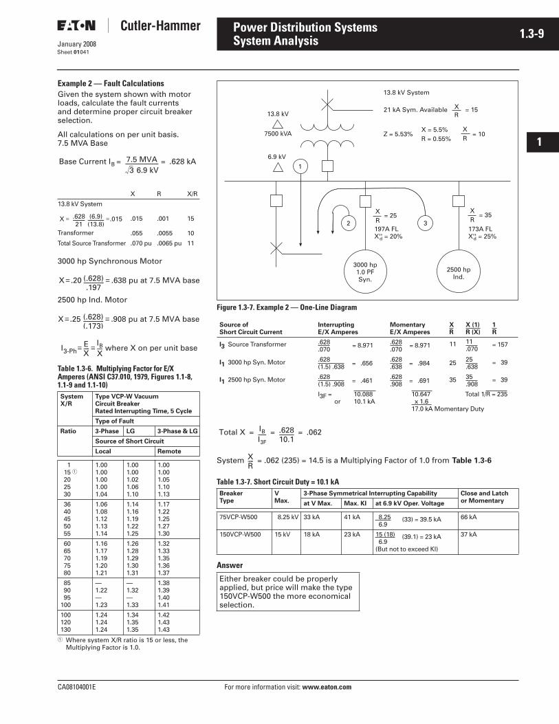
CA08104001E For more information visit: www.eaton.com
1.3-9January 2008
Power Distribution Systems
i
ii
1
2
3
4
5
6
7
8
9
10
11
12
13
14
15
16
17
18
19
20
21
Sheet 01
System Analysis041
Example 2 — Fault CalculationsGiven the system shown with motor loads, calculate the fault currents and determine proper circuit breaker selection.
All calculations on per unit basis. 7.5 MVA Base
3000 hp Synchronous Motor
2500 hp Ind. Motor
Table 1.3-6. Multiplying Factor for E/X Amperes (ANSI C37.010, 1979, Figures 1.1-8, 1.1-9 and 1.1-10)
� Where system X/R ratio is 15 or less, the Multiplying Factor is 1.0.
X R X/R
13.8 kV System
Transformer
.015
.055
.001
.0055
15
10
Total Source Transformer .070 pu .0065 pu 11
SystemX/R
Type VCP-W Vacuum Circuit Breaker Rated Interrupting Time, 5 Cycle
Type of Fault
Ratio 3-Phase LG 3-Phase & LG
Source of Short Circuit
Local Remote
1 15 � 20 25 30
1.001.001.001.001.04
1.001.001.021.061.10
1.001.001.051.101.13
36 40 45 50 55
1.061.081.121.131.14
1.141.161.191.221.25
1.171.221.251.271.30
60 65 70 75 80
1.161.171.191.201.21
1.261.281.291.301.31
1.321.331.351.361.37
85 90 95100
—1.22—1.23
—1.32—1.33
1.381.391.401.41
100120130
1.241.241.24
1.341.351.35
1.421.431.43
Base Current IB7.5 MVA3 6.9 kV
------------------------------- .628 kA= =
X .62821
----------- (6.9)(13.8)--------------- .015= =
X .20 (.628).197
------------------- .638 pu at 7.5 MVA base= =
X .25 (.628)(.173)------------------- .908 pu at 7.5 MVA base= =
I3-PhEX-----
IB
X----- where X on per unit base= =
Figure 1.3-7. Example 2 — One-Line Diagram
System = .062 (235) = 14.5 is a Multiplying Factor of 1.0 from Table 1.3-6
Table 1.3-7. Short Circuit Duty = 10.1 kA
Answer
Source ofShort Circuit Current
InterruptingE/X Amperes
MomentaryE/X Amperes
XR
X (1)R (X)
1R
I3 Source Transformer .628.070
= 8.971 .628.070
= 8.971 11 11.070
= 157
I1 3000 hp Syn. Motor .628(1.5) .638 = .656 .628
.638 = .984 25 25.638
= 39
I1 2500 hp Syn. Motor .628(1.5) .908 = .461 .628
.908 = .691 35 35.908
= 39
I3F = 10.088 or 10.1 kA
10.647 Total 1/R = 235 x 1.6 17.0 kA Momentary Duty
Z = 5.53% = 10
13.8 kV
7500 kVA
6.9 kV
13.8 kV System
3
21 kA Sym. Available = 15XR
X = 5.5%R = 0.55%
XR
XR
= 25XR
= 35
3000 hp1.0 PFSyn.
2500 hpInd.
2197A FLX'' = 20%d
173A FLX'' = 25%d
1
Total X IB
I3F-------- .628
10.1-------------- .062= = =
BreakerType
VMax.
3-Phase Symmetrical Interrupting Capability Close and Latchor Momentaryat V Max. Max. KI at 6.9 kV Oper. Voltage
75VCP-W500 8.25 kV 33 kA 41 kA 8.25 6.9
(33) = 39.5 kA 66 kA
150VCP-W500 15 kV 18 kA 23 kA 15 (18) 6.9
(39.1) = 23 kA
(But not to exceed KI)
37 kA
XR-----
Either breaker could be properly applied, but price will make the type 150VCP-W500 the more economical selection.
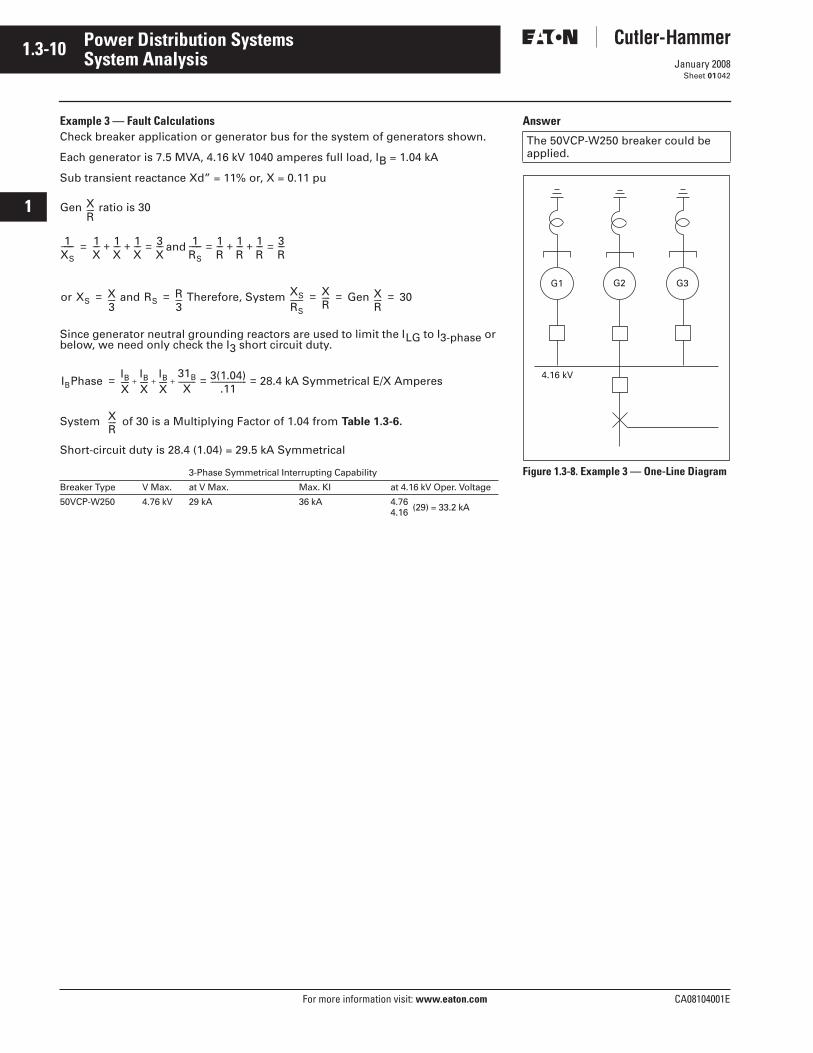
1.3-10
For more information visit: www.eaton.com CA08104001E
January 2008
Power Distribution Systems
i
ii
1
2
3
4
5
6
7
8
9
10
11
12
13
14
15
16
17
18
19
20
21
Sheet 01
System Analysis042
Example 3 — Fault CalculationsCheck breaker application or generator bus for the system of generators shown.
Each generator is 7.5 MVA, 4.16 kV 1040 amperes full load, IB = 1.04 kA
Sub transient reactance Xd” = 11% or, X = 0.11 pu
Since generator neutral grounding reactors are used to limit the ILG to I3-phase or below, we need only check the I3 short circuit duty.
System of 30 is a Multiplying Factor of 1.04 from Table 1.3-6.
Short-circuit duty is 28.4 (1.04) = 29.5 kA Symmetrical
Gen XR----- ratio is 30
3-Phase Symmetrical Interrupting Capability
Breaker Type V Max. at V Max. Max. KI at 4.16 kV Oper. Voltage
50VCP-W250 4.76 kV 29 kA 36 kA 4.764.16 (29) = 33.2 kA
1XS−−−− 1
X−− 1
X−− 1
X−− 3
X−− and 1
RS−−−− 1
R−− 1
R−− 1
R−− 3
R−−=+ +==+ +=
or XSX3----- and RS
R3---- Therefore, System XS
RS--------
XR----- Gen X
R----- 30= = = = =
IBPhaseIBX-----
IBX-----
IBX-----
31B
X----------- 3(1.04)
.11----------------------- 28.4 kA Symmetrical E/X Amperes= =+ + +=
XR-----
Answer
Figure 1.3-8. Example 3 — One-Line Diagram
The 50VCP-W250 breaker could be applied.
G1 G2 G3
4.16 kV
CA08104001E For more information visit: www.eaton.com
1.3-11January 2008
Power Distribution Systems
i
ii
1
2
3
4
5
6
7
8
9
10
11
12
13
14
15
16
17
18
19
20
21
Sheet 01
System Analysis043
Medium Voltage Fuses — Fault CalculationsThere are two basic types of medium voltage fuses. The following definitions are taken from ANSI Standard C37.40.
Expulsion Fuse (Unit)A vented fuse (unit) in which the expulsion effect of the gases produced by internal arcing, either alone or aided by other mechanisms, results in current interruption.
Current-Limiting Fuse (Unit)A fuse unit that, when its current-responsive element is melted by a current within the fuse’s specified current- limiting range, abruptly introduces a high resistance to reduce current magnitude and duration, resulting in subsequent current interruption.
There are two classes of fuses; power and distribution. They are distinguished from each other by the current ratings and minimum melting type characteristics.
The current limiting ability of a current limiting fuse is specified by its threshold ratio, peak let-through current and I2t characteristics.
Interrupting Ratings of FusesModern fuses are rated in amperes rms symmetrical. They also have a listed asymmetrical rms rating which is 1.6 x the symmetrical rating.
Refer to ANSI/IEEE C37.48 for fuse interrupting duty guidelines.
Calculation of the Fuse Required Interrupting Rating:Step 1 — Convert the fault from the utility to percent or per unit on a convenient voltage and kVA base.
Step 2 — Collect the X and R data of all the other circuit elements and convert to a percent or per unit on a conve-nient kVA and voltage base same as that used in Step 1. Use the substran-sient X and R for all generators and motors.
Step 3 — Construct the sequence networks using reactances and connect properly for the type of fault under consideration and reduce to a single equivalent reactance.
Step 4 — Construct the sequence networks using resistances and connect properly for the type of fault under consideration and reduce to a single equivalent resistance.
Step 5 — Calculate the E/XI value, where E is the prefault value of the voltage at the point of fault normally assumed 1.0 in pu. For 3-phase faults E/XI is the fault current to be used in determining the required interrupting capability of the fuse.
Note: It is not necessary to calculate a single phase-to-phase fault current. This current is very nearly /2 x 3-phase fault. The line-to-ground fault may exceed the 3-phase fault for fuses located in generating stations with solidly grounded neutral generators, or in delta-wye transformers with the wye solidly grounded, where the sum of the positive and negative sequence impedances on the high voltage side (delta) is smaller than the impedance of the transformer.
For single line-to-ground fault;
Step 6 — Select a fuse whose published interrupting rating exceeds the calculated fault current.
Figure 1.3-2 should be used where older fuses asymmetrically rated are involved.
The voltage rating of power fuses used on 3-phase systems should equal or exceed the maximum line-to-line voltage rating of the system. Current limiting fuses for 3-phase systems should be so applied that the fuse voltage rating is equal to or less than 1.41 x nominal system voltage.
Low Voltage Power Circuit Breakers — Fault CalculationsThe steps for calculating the fault cur-rent for the selection of a low voltage power circuit breaker are the same as those used for medium voltage circuit breakers except that where the con-nected loads to the low voltage bus
includes induction and synchronous motor loads. The assumption is made that in 208Y/120-volt systems the contribution from motors is 2 times the full load current of step-down trans-former. This corresponds to an assumed 50% motor aggregate impedance on a kVA base equal to the transformer kVA rating or 50% motor load. For 480-, 480Y/277- and 600-volt systems the assumption is made that the contribu-tion from the motors is four times the full load current of the step-down transformer which corresponds to an assumed 25% aggregate motor imped-ance on a kVA base equal to the trans-former kVA rating or 100% motor load.
In low voltage systems which contain generators the subtransient reactance should be used.
If the X/R to the point of fault is greater than 6.6, a derating multiplying factor (MF) must be applied. The X/R ratio is calculated in the same manner as that for medium voltage circuit breakers.
Calculated symmetrical amperes x MF ≤ breaker interrupting rating.
The multiplying factor MF can be calculated by the formula:
If the X/R of system feeding the breaker is not known, use X/R = 15.
For fused breakers by the formula:
If the X/R of the system feeding the breaker is not known, use X/R = 20.
Refer to Table 1.3-8 for the standard ranges of X/R and Power Factors used in testing and rating low voltage break-ers. Refer to Table 1.3-9 for the circuit breaker interrupting rating multiplying factors to be used when the calculated X/R ratio or power factor at the point the breaker is to be applied in the power distribution system falls outside of the Table 1.3-8 X/R or power factors used in testing and rating the circuit breakers. MF is always greater than 1.0.
3
XI XI(+) XI(–) XI(0)+ +=
IfEXI------ 3×=
MF 2 1 2.718 π( ) X/R( )⁄–+[ ]2.29
−−−−−−−−−−−−−−−−−−−−−−−−−−−−−−−−−−−−−−=
MF 1 2 2.718( ) 2π( ) X/R( )⁄–×+1.25
−−−−−−−−−−−−−−−−−−−−−−−−−−−−−−−−−−−−−−−−−=
1.3-12
For more information visit: www.eaton.com CA08104001E
January 2008
Power Distribution Systems
i
ii
1
2
3
4
5
6
7
8
9
10
11
12
13
14
15
16
17
18
19
20
21
Sheet 01
System Analysis044
Molded Case Breakers and Insulated Case Circuit Breakers — Fault CalculationsThe method of fault calculation is the same as that for low voltage power circuit breakers. Again the calculated fault current x MF ≤ breaker interrupt-ing capacity. Because molded case breakers are tested at lower X/R ratios the MFs are different than those for low voltage power circuit breakers.
MF 1 2.718π
X2
R2−−−
⁄–+
1 2.718π
X1
R1−−−
⁄–+
----------------------------------------------------=
X1 R1 test X/R value.=⁄
X2 R2X/R at point where breakeris applied.
=⁄
Low Voltage Circuit Breaker Interrupting Derating FactorsRefer to Table 1.3-8 for the standard ranges of X/R and power factors used in testing and rating low voltage breakers. Refer to Table 1.3-9 for the circuit breaker interrupting rating de-rating factors to be used when the calculated X/R ratio or power factor at the point the breaker is to be applied in the power distribution system falls outside of the Table 1.3-8 X/R or power factors used in testing and rating the circuit breakers.
Normally the short circuit power factor or X/R ratio of a distribution system need not be considered in applying low voltage circuit breakers. This is because the ratings established in the applicable standard are based on power factor values which amply cover most applications.
Established standard values include the following:
Table 1.3-8. Standard Test Power Factors
For distribution systems where the calculated short circuit current X/R ratio differs from the standard values given in the above table, circuit breaker interrupting rating derating factors from Table 1.3-9 table should be applied.
Table 1.3-9. Circuit Breaker Interrupting Rating Derating Factors
Note: These are derating factors applied to the breaker and are the inverse of MF.
InterruptingRating in kA
Power FactorTest Range
X/R TestRange
Molded Case Circuit Breaker10 or LessOver 10 to 20Over 20
.45 – .50
.25 – .30
.15 – .20
1.98 – 1.733.87 – 3.186.6 – 4.9
Low Voltage Power Circuit BreakerAll .15 Maximum 6.6 Minimum
% P.F. X/R Interrupting Rating
Molded Case or Insulated Case Power Circuit Breaker
/ = 10 kA>10 kA
/ = 20 kA >20 kA Unfused Fused
503025
1.73 3.18 3.87
1.000 .847 .805
1.0001.000 .950
1.0001.0001.000
1.0001.0001.000
1.0001.0001.000
201512
4.90 6.59 8.27
.762 .718 .691
.899 .847 .815
1.000 .942 .907
1.0001.000 .962
1.000 .939 .898
10 8.5 7
9.9511.7214.25
.673 .659 .645
.794 .778 .761
.883 .865 .847
.937 .918 .899
.870 .849 .827
5 19.97 .627 .740 .823 .874 .797
< <
CA08104001E For more information visit: www.eaton.com
1.3-13January 2008
Power Distribution Systems
i
ii
1
2
3
4
5
6
7
8
9
10
11
12
13
14
15
16
17
18
19
20
21
Sheet 01
System Analysis045
Short Circuit Calculations — Short Cut Method
Determination of Short Circuit CurrentNote 1: Transformer impedance generally relates to self-ventilated rating (e.g., with OA/FA/FOA transformer use OA base). Note 2: kV refers to line-to-line voltage in kilovolts. Note 3: Z refers to line-to-neutral impedance of system to fault where R + jX = Z. Note 4: When totaling the components of system Z, arithmetic combining of impedances as “ohms Z”. “per unit Z”. etc., is considered a
short cut or approximate method; proper combining of impedances (e.g., source, cables transformers, conductors, etc). should use individual R and X components. This Total Z = Total R + j Total X (See IEEE “Red Book” Standard No. 141).
(a) Per unit = pu impedance kVA base
(b) Percent = % impedance kVA base
(a) Per unit impedance = pu
(b) % impedance = %
(c) Ohms impedance =
(a) — if utility fault capacity given in kVA
Per-unit impedance = pu
(b) — if utility fault capacity given in rms symmetrical short circuit amperes
Per-unit impedance = pu
(a) — motor kVA — (kV) (I) where I = motor nameplate full-load amperes
(b) — if 1.0 power factor synchronous motor kVA = (0.8) (hp)
(c) — if 0.8 power factor synchronous motor kVA = (1.0) (hp)
(d) — if induction motor kVA = (1.0) (hp)
(a) Base current = I Base = or
(b) Per unit
(c) rms Symmetrical current = ISC = (pu ISC) (IBase Amperes)
(d) rms Symmetrical current = Amperes = or
(e) = or
(g) =
(a) Symmetrical short circuit kVA =
(b) =
(a) — from 3-phase transformer — approx. 86% of 3-phase current
(b) — three single-phase transformers (e.g., 75 kVA, Z = 2%) calculate same as one 3-phase unit (i.e., 3 x 75 kVA = 225 kVA, Z = 2%).
(c) — from single-phase transformer — see Page 1.3-15.
(a) — synchronous motor — 5 times motor full load current (impedance 20%)
(b) — induction motor — 4 times motor full-load current (impedance 25%)
(c) — motor loads not individually identified, use contribution from group of motors as follows:— on 208Y/120 volt systems — 2.0 times transformer full-load current— on 240-480-600 volt 3-phase, 3-wire systems — 4.0 times transformer full-load current— on 480Y/277 volt 3-phase, 4-wire systems— In commercial buildings, 2.0 times transformers full-load current (50% motor load)— In industrial plants, 4.0 times transformer full-load current (100% motor load)
2 kVA base 2kVA base 1−−−−−−−−−−−−−−− (pu impedance on kVA base 1)×=
2 kVA base 2kVA base 1−−−−−−−−−−−−−−− (% impedance on kVA base 1)×=
Z percent impedance100
−−−−−−−−−−−−−−−−−−−−−−−−−−− (ohms impedance)kV( )2
−−−−−−−−−−−−−−−−−−−−−−−−−−(kVA base)1000( )
−−−−−−−−−−−−−−−= =
Z (ohms impedance)kV( )2
−−−−−−−−−−−−−−−−−−−−−−−−−−(kVA base)10( )
−−−−−−−−−−−−−−−=
(% impedance) kV( )2 (10)kVA base
−−−−−−−−−−−−−−−−−−−−−−−−−−−−−−−−−−
Z kVA base in studypower-source kVA fault capacity-------------------------------------------------------------------------------------------=
Z kVA base in study(short-circuit current) 3( )(kV of source)----------------------------------------------------------------------------------------------------------------=
3( )
3-phase kVA
3( ) kV( )−−−−−−−−−−−−−−−−− 1-phase kVA
kV line-to-neutral−−−−−−−−−−−−−−−−−−−−−−−−
ISC1.0
puZ−−−−−=
3-phase kVA basepuZ( ) 3( ) kV( )
-------------------------------------------------- 1-phase kVA basepuZ( ) kV( )
--------------------------------------------------
(3-phase kVA base) (100)(%Z) 3( ) kV( )
---------------------------------------------------------------------- 1-phase kVA base (100)(%Z) kV( )
------------------------------------------------------------------
(kV) (1000)3 (ohms Z)
-----------------------------------
kVA basepuZ( )
-------------------------- (kVA base) (100)%Z
---------------------------------------------- kV( )2 1000( )ohms Z
----------------------------------= =
3(line-to-neutral kV)2 1000( )(ohms Z)
-----------------------------------------------------------------------------
1. Select convenient kVA base for system to be studied.
2. Change per unit, or percent, impedance from one kVA base to another:
3. Change ohms, or percent or per-unit, etc.:
4. Change power-source impedance to per-unit or percent impedance on kVA base as selected for this study:
5. Change motor rating to kVA:
6. Determine symmetrical short circuit current:
7. Determine symmetrical short circuit kVA:
8. Determine line-to-line short circuit current:
9. Determine motor contribution (or feedback) as source of fault current: �See IEEE
Standard No. 141
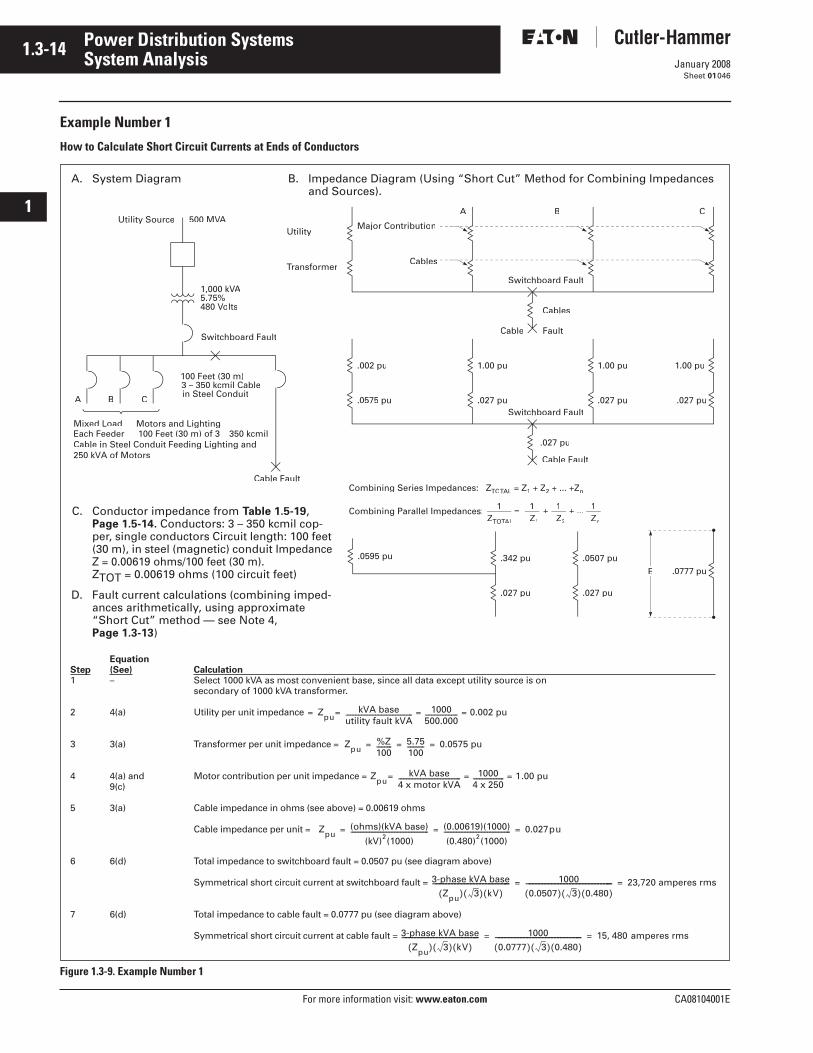
1.3-14
For more information visit: www.eaton.com CA08104001E
January 2008
Power Distribution Systems
i
ii
1
2
3
4
5
6
7
8
9
10
11
12
13
14
15
16
17
18
19
20
21
Sheet 01
System Analysis046
Example Number 1
How to Calculate Short Circuit Currents at Ends of Conductors
Figure 1.3-9. Example Number 1
Utility Source 500 MVAVV
1,000 kVAVV5.75%480 Volts
Switchboard Fault
100 Feet (30 m)3 – 350 kcmil Cablein Steel Conduit
Mixed Load — Motors and LightingEach Feeder — 100 Feet (30 m) of 3 – 350 kcmil Cable in Steel Conduit Feeding Lighting and250 kVA of Motors
Cable Fault
Utility
Transformer
Major Contribution
Cables
Switchboard Fault
Cables
Cable Fault
A B C
.002 pu
Switchboard Fault
.027 pu
Cable Fault
A B C .0575 pu
1.00 pu
.027 pu
1.00 pu
.027 pu
1.00 pu
.027 pu
.342 pu
.027 pu
.0507 pu
.027 pu
E .0777 pu
Combining Series Impedances: ZTO L = 1 + Z2 + ... +Zn
Combining Parallel Impedances:ZTOTAL
1 =Z1
1 +Z2
1 + ...Zn
1
.0595 pu
EquationStep (See) Calculation 1 – Select 1000 kVA as most convenient base, since all data except utility source is on
secondary of 1000 kVA transformer.
2 4(a) Utility per unit impedance
3 3(a) Transformer per unit impedance =
4 4(a) and Motor contribution per unit impedance = 9(c)
5 3(a) Cable impedance in ohms (see above) = 0.00619 ohms
Cable impedance per unit =
6 6(d) Total impedance to switchboard fault = 0.0507 pu (see diagram above)
Symmetrical short circuit current at switchboard fault =
7 6(d) Total impedance to cable fault = 0.0777 pu (see diagram above)
Symmetrical short circuit current at cable fault =
ZpukVA base
utility fault kVA------------------------------------------- 1000
500.000--------------------- 0.002 pu= ===
Zpu%Z100---------- 5.75
100----------- 0.0575 pu= = =
ZpukVA base
4 x motor kVA---------------------------------------- 1000
4 x 250-------------------- 1.00 pu= ==
Zpu(ohms)(kVA base)
(kV)2(1000)-------------------------------------------------- (0.00619)(1000)
(0.480)2(1000)------------------------------------------- 0.027pu= = =
3-phase kVA base
Zpu( ) 3( ) kV( )−−−−−−−−−−−−−−−−−−−−−−−−− 1000
0.0507( ) 3( ) 0.480( )−−−−−−−−−−−−−−−−−−−−−−−−−−−− 23,720 amperes rms= =
3-phase kVA base
Zpu( ) 3( ) kV( )−−−−−−−−−−−−−−−−−−−−−−−−− 1000
0.0777( ) 3( ) 0.480( )−−−−−−−−−−−−−−−−−−−−−−−−−−−− 15 480 amperes rms,= =
A. System Diagram B. Impedance Diagram (Using “Short Cut” Method for Combining Impedances and Sources).
C. Conductor impedance from Table 1.5-19, Page 1.5-14. Conductors: 3 – 350 kcmil cop-per, single conductors Circuit length: 100 feet (30 m), in steel (magnetic) conduit Impedance Z = 0.00619 ohms/100 feet (30 m).ZTOT = 0.00619 ohms (100 circuit feet)
D. Fault current calculations (combining imped-ances arithmetically, using approximate “Short Cut” method — see Note 4, Page 1.3-13)
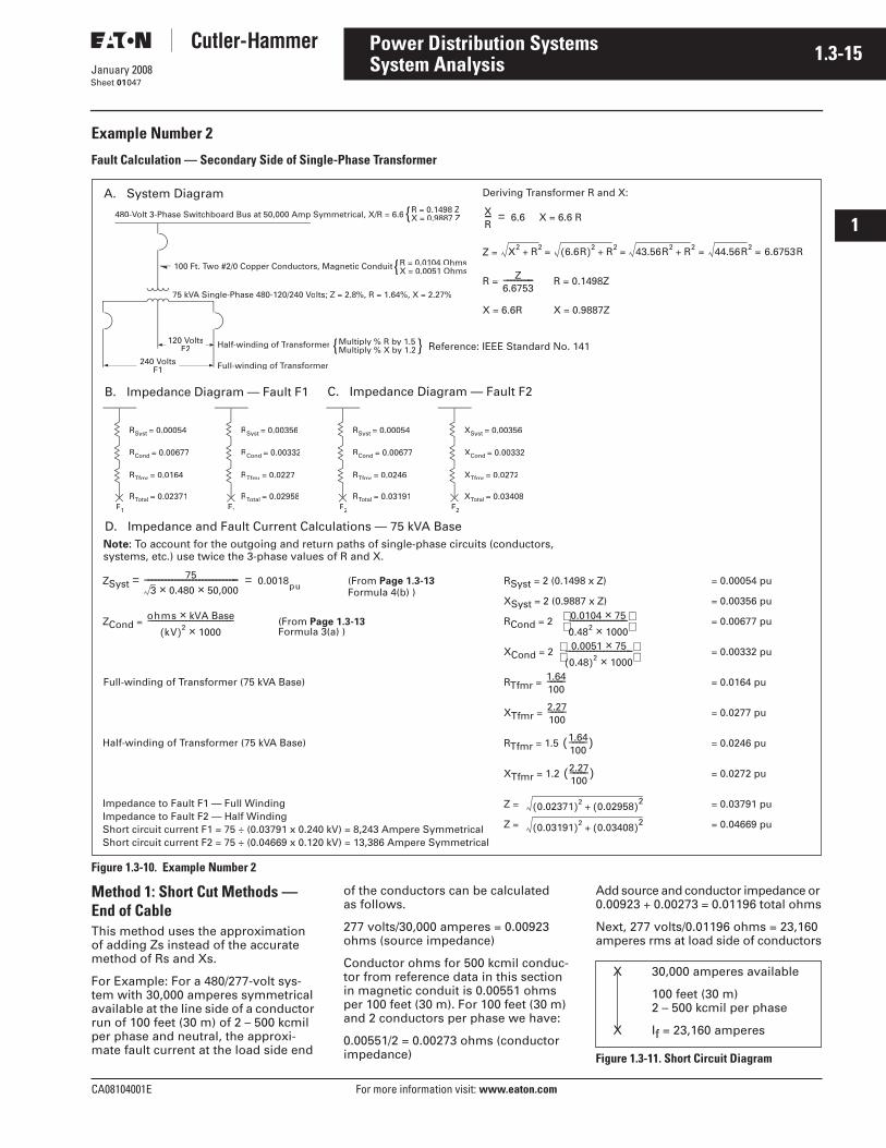
CA08104001E For more information visit: www.eaton.com
1.3-15January 2008
Power Distribution Systems
i
ii
1
2
3
4
5
6
7
8
9
10
11
12
13
14
15
16
17
18
19
20
21
Sheet 01
System Analysis047
Example Number 2
Fault Calculation — Secondary Side of Single-Phase Transformer
Figure 1.3-10. Example Number 2
Method 1: Short Cut Methods — End of CableThis method uses the approximation of adding Zs instead of the accurate method of Rs and Xs.
For Example: For a 480/277-volt sys-tem with 30,000 amperes symmetrical available at the line side of a conductor run of 100 feet (30 m) of 2 – 500 kcmil per phase and neutral, the approxi-mate fault current at the load side end
of the conductors can be calculated as follows.
277 volts/30,000 amperes = 0.00923 ohms (source impedance)
Conductor ohms for 500 kcmil conduc-tor from reference data in this section in magnetic conduit is 0.00551 ohms per 100 feet (30 m). For 100 feet (30 m) and 2 conductors per phase we have:
0.00551/2 = 0.00273 ohms (conductor impedance)
Add source and conductor impedance or 0.00923 + 0.00273 = 0.01196 total ohms
Next, 277 volts/0.01196 ohms = 23,160 amperes rms at load side of conductors
Figure 1.3-11. Short Circuit Diagram
RSyst = 0.00054
RCond = 0.00677
RTfmr = 0.0164
RTotalTT = 0.02371F1
RSyst = 0.00356
RCond = 0.00332
RTfmr = 0.0227
RTotalTT = 0.02958F1
RSyst = 0.00054
RCond = 0.00677
RTfmr = 0.0246
RTotalTT = 0.03191F2
XSyst = 0.00356
XCond = 0.00332
XTfmr = 0.0272
XTotalTT = 0.03408F2
240 VF1
120 VoltsF2 Half-winding of Transformer
Full-winding of Transformer
{Multiply % R by 1.5Multiply % X by 1.2 }
75 kVA Single-Phase 480-120/240VV Volts; Z = 2.8%, R = 1.64%, X = 2.27%
100 Ft. Two #2/0 Copper Conductors, Magnetic Conduit{R = 0.0104 OhmsX = 0.0051 Ohms
480-Volt 3-Phase Switchboard Bus at 50,000 Amp Symmetrical, X/R = 6.6{R = 0.1498 ZX = 0.9887 Z
ZCond = (From Page 1.3-13Formula 3(a) )
ohms kVA Base×kV( )2 1000×
−−−−−−−−−−−−−−−−−−−−−−−−−
A. System Diagram Deriving Transformer R and X:
X = 6.6 R
Z =
R = R = 0.1498Z
X = 6.6R X = 0.9887Z
XR−− 6.6=
X2 R2+ 6.6R( )2 R2+ 43.56R2 R2+ 44.56R2 6.6753R= = = =
Z6.6753−−−−−−−−−
B. Impedance Diagram — Fault F1
D. Impedance and Fault Current Calculations — 75 kVA BaseNote: To account for the outgoing and return paths of single-phase circuits (conductors, systems, etc.) use twice the 3-phase values of R and X.
RSyst = 2 (0.1498 x Z) = 0.00054 pu
XSyst = 2 (0.9887 x Z) = 0.00356 pu
RCond = 2 = 0.00677 pu
XCond = 2 = 0.00332 pu
RTfmr = = 0.0164 pu
XTfmr = = 0.0277 pu
RTfmr = 1.5 = 0.0246 pu
XTfmr = 1.2 = 0.0272 pu
Z = = 0.03791 pu
Z = = 0.04669 pu
0.0104 75×0.482 1000×−−−−−−−−−−−−−−−−−
0.0051 75×0.48( )2 1000×
−−−−−−−−−−−−−−−−−−−−
1.64100−−−−−
2.27100−−−−−
1.64100−−−−−( )
2.27100−−−−−( )
0.02371( )2 0.02958( )2+
0.03191( )2 0.03408( )2+
ZSyst = (From Page 1.3-13Formula 4(b) )
75
3 0.480× 50,000×−−−−−−−−−−−−−−−−−−−−−−−−−−−− 0.0018pu=
Full-winding of Transformer (75 kVA Base)
Half-winding of Transformer (75 kVA Base)
Impedance to Fault F1 — Full WindingImpedance to Fault F2 — Half WindingShort circuit current F1 = 75 ÷ (0.03791 x 0.240 kV) = 8,243 Ampere SymmetricalShort circuit current F2 = 75 ÷ (0.04669 x 0.120 kV) = 13,386 Ampere Symmetrical
C. Impedance Diagram — Fault F2
Reference: IEEE Standard No. 141
X 30,000 amperes available
100 feet (30 m)2 – 500 kcmil per phase
X If = 23,160 amperes
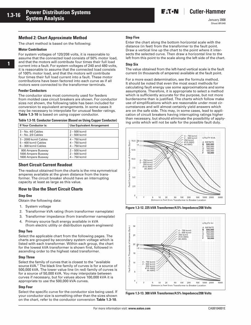
1.3-16
For more information visit: www.eaton.com CA08104001E
January 2008
Power Distribution Systems
i
ii
1
2
3
4
5
6
7
8
9
10
11
12
13
14
15
16
17
18
19
20
21
Sheet 01
System Analysis048
Method 2: Chart Approximate MethodThe chart method is based on the following:
Motor ContributionFor system voltages of 120/208 volts, it is reasonable to assume that the connected load consists of 50% motor load, and that the motors will contribute four times their full load current into a fault. For system voltages of 240 and 480 volts, it is reasonable to assume that the connected load consists of 100% motor load, and that the motors will contribute four times their full load current into a fault. These motor contributions have been factored into each curve as if all motors were connected to the transformer terminals.
Feeder ConductorsThe conductor sizes most commonly used for feeders from molded case circuit breakers are shown. For conductor sizes not shown, the following table has been included for conversion to equivalent arrangements. In some cases it may be necessary to interpolate for unusual feeder ratings. Table 1.3-10 is based on using copper conductor.
Table 1.3-10. Conductor Conversion (Based on Using Copper Conductor)
Short Circuit Current ReadoutThe readout obtained from the charts is the rms symmetrical amperes available at the given distance from the trans-former. The circuit breaker should have an interrupting capacity at least as large as this value.
How to Use the Short Circuit ChartsStep OneObtain the following data:
1. System voltage2. Transformer kVA rating (from transformer nameplate)3. Transformer impedance (from transformer nameplate)4. Primary source fault energy available in kVA
(from electric utility or distribution system engineers)
Step TwoSelect the applicable chart from the following pages. The charts are grouped by secondary system voltage which is listed with each transformer. Within each group, the chart for the lowest kVA transformer is shown first, followed in ascending order to the highest rated transformer.
Step ThreeSelect the family of curves that is closest to the “available source kVA.” The black line family of curves is for a source of 500,000 kVA. The lower value line (in red) family of curves is for a source of 50,000 kVA. You may interpolate between curves if necessary, but for values above 100,000 kVA it is appropriate to use the 500,000 kVA curves.
Step FourSelect the specific curve for the conductor size being used. If your conductor size is something other than the sizes shown on the chart, refer to the conductor conversion Table 1.3-10.
Step FiveEnter the chart along the bottom horizontal scale with the distance (in feet) from the transformer to the fault point. Draw a vertical line up the chart to the point where it inter-sects the selected curve. Then draw a horizontal line to the left from this point to the scale along the left side of the chart.
Step SixThe value obtained from the left-hand vertical scale is the fault current (in thousands of amperes) available at the fault point.
For a more exact determination, see the formula method. It should be noted that even the most exact methods for calculating fault energy use some approximations and some assumptions. Therefore, it is appropriate to select a method which is sufficiently accurate for the purpose, but not more burdensome than is justified. The charts which follow make use of simplifications which are reasonable under most cir-cumstances and will almost certainly yield answers which are on the safe side. This may, in some cases, lead to appli-cation of circuit breakers having interrupting ratings higher than necessary, but should eliminate the possibility of apply-ing units which will not be safe for the possible fault duty.
Figure 1.3-12. 225 kVA Transformer/4.5% Impedance/208 Volts
Figure 1.3-13. 300 kVA Transformer/4.5% Impedance/208 Volts
If Your Conductor is: Use Equivalent Arrangement
3 – No. 4/0 Cables4 – No. 2/0 Cables
2 – 500 kcmil2 – 500 kcmil
3 – 2000 kcmil Cables5 – 400 kcmil Cables6 – 300 kcmil Cables
4 – 750 kcmil4 – 750 kcmil4 – 750 kcmil
800 Ampere Busway1000 Ampere Busway1600 Ampere Busway
2 – 500 kcmil2 – 500 kcmil4 – 750 kcmil
0 2 5 10 20 50 100 200 500 1000 2000 50000
2.5
5.0
7.5
10.0
12.5
Distance in Feet from T
250 kcmilWGWWGW
UTILITY KVAVV
0 2 5 10 20 50 100 200 500 1000 2000 50000
5
10
15
20
25
30
Fau
lt C
urr
ent
in T
ho
usa
nd
s o
f A
mp
eres
(S
ym.)
Distance in Feet from T
B
F
kcmil
#4 AA
KV
F 50,000

CA08104001E For more information visit: www.eaton.com
1.3-17January 2008
Power Distribution Systems
i
ii
1
2
3
4
5
6
7
8
9
10
11
12
13
14
15
16
17
18
19
20
21
Sheet 01
System Analysis049
Figure 1.3-14. 500 kVA Transformer/4.5% Impedance/208 Volts
Figure 1.3-15. 750 kVA Transformer/5.5% Impedance/208 Volts
Figure 1.3-16. 1000 kVA Transformer/5.5% Impedance/208 Volts
Figure 1.3-17. 1500 kVA Transformer/5.5% Impedance/208 Volts
Figure 1.3-18. 2000 kVA Transformer/5.5% Impedance/208 Volts
Figure 1.3-19. 300 kVA Transformer/4.5% Impedance/480 Volts
0 2 5 10 20 50 100 200 500 1000 2000 50000
5
10
15
20
25
30
Fau
lt C
urr
ent
in T
ho
usa
nd
s o
f A
mp
eres
(S
ym.)
Distance in Feet from T
B
F
42
KV
0 2 5 10 20 50 100 200 500 1000 2000 50000
10
20
30
40
50
60
Fau
lt C
urr
ent
in T
ho
usa
nd
s o
f A
mp
eres
(S
ym.)
Distance in Feet from T
B
F
4 – kcmil
–
WGW
AA
F 50,000
0 2 5 10 20 50 100 200 500 1000 2000 50000
10
20
30
40
50
60
Fau
lt C
urr
ent
in T
ho
usa
nd
s o
f A
mp
eres
(S
ym.)
Distance in Feet from T
B
F
WGW
kcmilkcmil
AA
F 50,000
0 2 5 10 20 50 100 200 500 1000 2000 50000
20
40
60
80
100
120
Distance in Feet from T
B
F
#4 AWGAA
WGW
AA
F 50,000
0 2 5 10 20 50 100 200 500 1000 2000 50000
20
40
60
80
100
120
Distance in Feet from T
B
F
–
WGW
AA
F 50,000
0 2 5 10 20 50 100 200 500 1000 2000 50000
2
4
6
8
10
12
Fau
lt C
urr
ent
in T
ho
usa
nd
s o
f A
mp
eres
(S
ym.)
Distance in Feet from T
B
42
AA
F 50,000
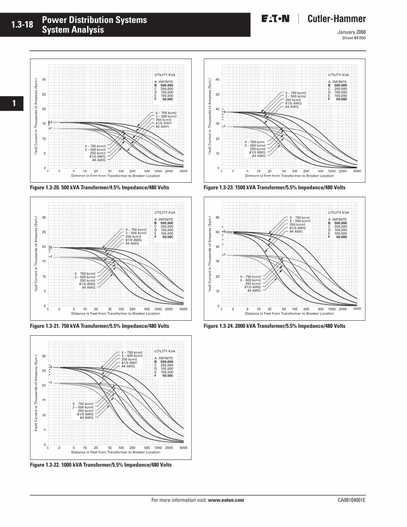
1.3-18
For more information visit: www.eaton.com CA08104001E
January 2008
Power Distribution Systems
i
ii
1
2
3
4
5
6
7
8
9
10
11
12
13
14
15
16
17
18
19
20
21
Sheet 01
System Analysis050
Figure 1.3-20. 500 kVA Transformer/4.5% Impedance/480 Volts
Figure 1.3-21. 750 kVA Transformer/5.5% Impedance/480 Volts
Figure 1.3-22. 1000 kVA Transformer/5.5% Impedance/480 Volts
Figure 1.3-23. 1500 kVA Transformer/5.5% Impedance/480 Volts
Figure 1.3-24. 2000 kVA Transformer/5.5% Impedance/480 Volts
0 2 5 10 20 50 100 200 500 1000 2000 50000
5
10
15
20
25
30
Fau
lt C
urr
ent
in T
ho
usa
nd
s o
f A
mp
eres
(S
ym.)
Distance in Feet from T
B
AA
F 50,000
–
#1/0 AWGAA#4 AWGAA
0 2 5 10 20 50 100 200 500 1000 2000 50000
5
10
15
20
25
30
Fau
lt C
urr
ent
in T
ho
usa
nd
s o
f A
mp
eres
(S
ym.)
Distance in Feet from T
B
F
AA
F 50,000
4 – kcmil
#4 AA
750500
0 2 5 10 20 50 100 200 500 1000 2000 50000
5
10
15
20
25
30
Fau
lt C
urr
ent
in T
ho
usa
nd
s o
f A
mp
eres
(S
ym.)
Distance in Feet from T
B
F
AA
F 50,000
4 – 750 kcmil2
WGW
0 2 5 10 20 50 100 200 500 1000 2000 50000
10
20
30
40
50
60
Fau
lt C
urr
ent
in T
ho
usa
nd
s o
f A
mp
eres
(S
ym.)
Distance in Feet from T
B
F
AA
F 50,000
4 750 kcmil
kcmil
#4 AWGAA
0 2 5 10 20 50 100 200 500 1000 2000 50000
10
20
30
40
50
60
Fau
lt C
urr
ent
in T
ho
usa
nd
s o
f A
mp
eres
(S
ym.)
Distance in Feet from T
B
F
AA
F 50,000
4 – kcmil
WGW
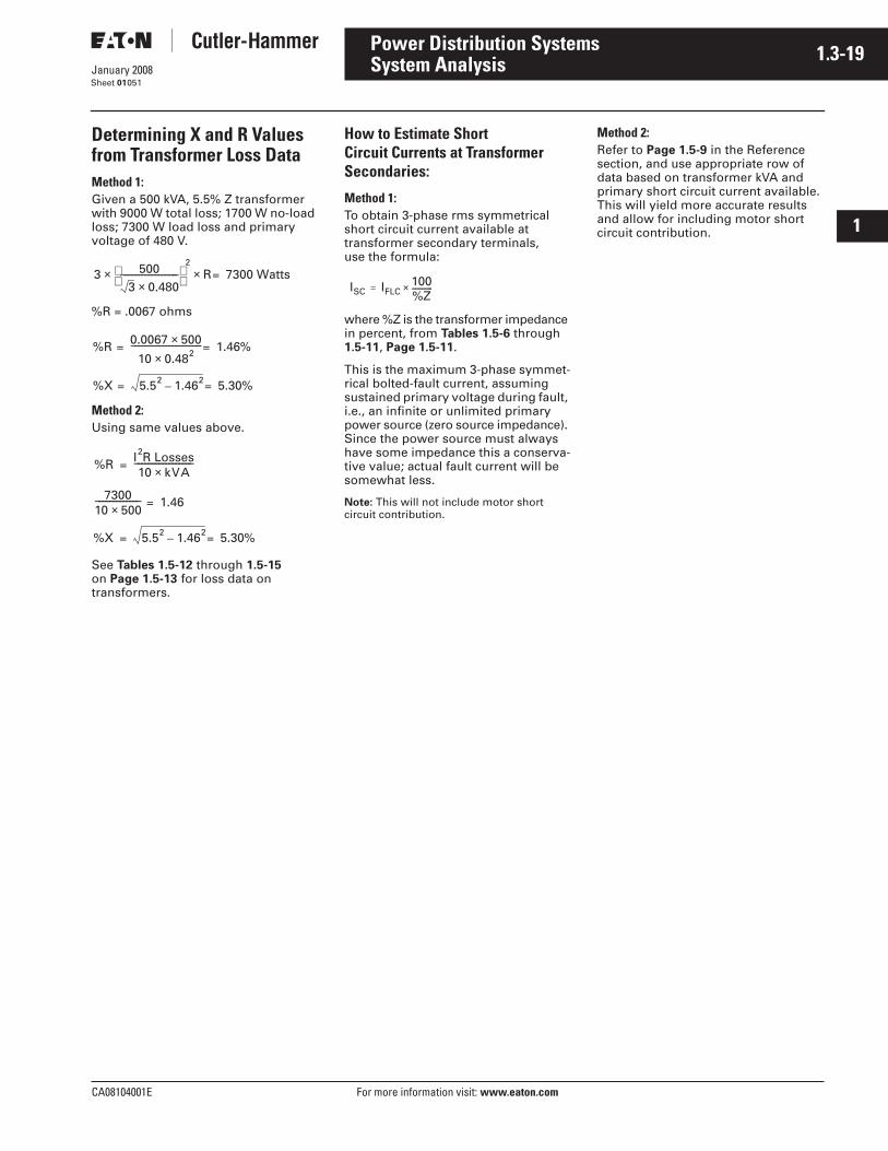
CA08104001E For more information visit: www.eaton.com
1.3-19January 2008
Power Distribution Systems
i
ii
1
2
3
4
5
6
7
8
9
10
11
12
13
14
15
16
17
18
19
20
21
Sheet 01
System Analysis051
Determining X and R Values from Transformer Loss DataMethod 1:Given a 500 kVA, 5.5% Z transformer with 9000 W total loss; 1700 W no-load loss; 7300 W load loss and primary voltage of 480 V.
%R = .0067 ohms
Method 2:Using same values above.
See Tables 1.5-12 through 1.5-15 on Page 1.5-13 for loss data on transformers.
How to Estimate Short Circuit Currents at Transformer Secondaries:
Method 1:To obtain 3-phase rms symmetrical short circuit current available at transformer secondary terminals, use the formula:
where %Z is the transformer impedance in percent, from Tables 1.5-6 through 1.5-11, Page 1.5-11.
This is the maximum 3-phase symmet-rical bolted-fault current, assuming sustained primary voltage during fault, i.e., an infinite or unlimited primary power source (zero source impedance). Since the power source must always have some impedance this a conserva-tive value; actual fault current will be somewhat less.
Note: This will not include motor short circuit contribution.
Method 2:Refer to Page 1.5-9 in the Reference section, and use appropriate row of data based on transformer kVA and primary short circuit current available. This will yield more accurate results and allow for including motor short circuit contribution.
3 5003 0.480×
−−−−−−−−−−−−−−−−−
2
× R 7300 Watts=×
%R 0.0067 500×10 0.482×
−−−−−−−−−−−−−−−−−−−−− 1.46%==
%X 5.52 1.462– 5.30%==
%R I R Losses2
10 kVA×−−−−−−−−−−−−−−−−−=
730010 500×−−−−−−−−−−−−− 1.46=
%X 5.52 1.462– 5.30%==
ISC IFLC100%Z------------×=
1.3-20
For more information visit: www.eaton.com CA08104001E
January 2008
Power Distribution Systems
i
ii
1
2
3
4
5
6
7
8
9
10
11
12
13
14
15
16
17
18
19
20
21
Sheet 01
System Analysis052
Voltage Drop ConsiderationsThe first consideration for voltage drop is that under the steady-state conditions of normal load, the voltage at the utilization equipment must be adequate. Fine-print notes in the NEC recommend sizing feeders and branch circuits so that the maximum voltage drop-in either does not exceed 3%, with the total voltage drop for feeders and branch circuits not to exceed 5%, for efficiency of operation. (Fine print notes in the NEC are not mandatory.)
In addition to steady-state conditions, voltage drop under transient condi-tions, with sudden high-current, short-time loads, must be considered. The most common loads of this type are motor inrush currents during starting. These loads cause a voltage dip on the system as a result of the voltage drop in conductors, transformers and generators under the high current. This voltage dip can have numerous adverse effects on equipment in the system, and equipment and conduc-tors must be designed and sized to minimize these problems. In many cases, reduced-voltage starting of motors to reduce inrush current will be necessary.
Recommended Limits of Voltage VariationGeneral Illumination: Flicker in incandescent lighting from voltage dip can be severe; lumen output drops about three times as much as the voltage dips. That is, a 10% drop in voltage will result in a 30% drop in light output. While the lumen output drop in fluorescent lamps is roughly proportional to voltage drop, if the voltage dips about 25%, the lamp will go out momentarily and then restrike. For high-intensity discharge (HID) lamps such as mercury vapor, high-pressure sodium or metal halide, if the lamp goes out because of an excessive voltage dip, it will not restrike until it has cooled. This will require several minutes. These lighting flicker effects can be annoying, and in the case of HID lamps, sometimes serious. In areas where close work is being done, such as drafting rooms, precision assembly plants, and the like, even a slight variation, if repeated, can be very annoying, and reduce efficiency. Voltage variation in such areas should be held to 2 or 3% under motor-starting or other transient conditions.
Computer Equipment: With the proliferation of data-processing and computer- or microprocessor-controlled manufacturing, the sensitivity of com-puters to voltage has become an important consideration. Severe dips of short duration can cause a computer to “crash” — shut down completely, and other voltage transients caused by starting and stopping motors can cause data-processing errors. While voltage drops must be held to a mini-mum, in many cases computers will require special power-conditioning equipment to operate properly.
Industrial Plants: Where large motors exist, and unit substation transformers are relatively limited in size, voltage dips of as much as 20% may be per-missible in some cases, if they do not occur too frequently. Lighting is often supplied from separate transformers, and is minimally affected by voltage dips in the power systems. However, it is usually best to limit dips to between 5 and 10% at most. One critical consid-eration is that a large voltage dip can cause a dropout (opening) of magnetic motor contactors and control relays. The actual dropout voltage varies con-siderably among starters of different manufacturers. The only standard that exists is that of NEMA, which states that a starter must not drop out at 85% of its nominal coil voltage, allowing only a 15% dip. While most starters will tolerate considerably more volt-age dip before dropping out, limiting dip to 15% is the only way to ensure continuity of operation in all cases.
X-Ray Equipment: Medical x-ray and similar diagnostic equipment, such as CAT-scanners, are extremely sensitive to low voltage. They present a small, steady load to the system until the instant the x-ray tube is “fired.” This presents a brief but extremely high instantaneous momentary load. In some modern x-ray equipment, the firing is repeated rapidly to create multiple images. The voltage regula-tion must be maintained within the manufacturer’s limits, usually 2 to 3%, under these momentary loads, to ensure proper x-ray exposure.
Motor StartingMotor inrush on starting must be limited to minimize voltage dips. Table 1.3-11 on the next page will help select the proper type of motor starter for various motors, and to select generators of adequate size to limit voltage dip. See Section 30 for additional data on reduced voltage motor starting.
Utility SystemsWhere the power is supplied by a utility network, the motor inrush can be assumed to be small compared to the system capacity, and voltage at the source can be assumed to be constant during motor starting. Voltage dip resulting from motor starting can be calculated on the basis of the voltage drop in the conductors between the power source and the motor resulting from the inrush current. Where the utility system is limited, the utility will often specify the maximum permissible inrush current or the maximum hp motor they will permit to be started across-the-line.
Transformer ConsiderationsIf the power source is a transformer, and the inrush kVA or current of the motor being started is small compared to the full-rated kVA or current of the transformer, the transformer voltage dip will be small and may be ignored. As the motor inrush becomes a signifi-cant percentage of the transformer full-load rating, an estimate of the transformer voltage drop must be added to the conductor voltage drop to obtain the total voltage drop to the motor. Accurate voltage drop calcula-tion would be complex and depend upon transformer and conductor resistance, reactance, and impedance, as well as motor inrush current and power factor. However, an approxima-tion can be made on the basis of the low power-factor motor inrush current (30 – 40%) and impedance of the trans-former.
The allowable motor inrush current is determined by the total permissible voltage drop in transformer and con-ductors.
For example, if a 480 V transformer has an impedance of 5%, and the motor inrush current is 25% of the transformer full-load current (FLC), then the worst case voltage drop will be 0.25 x 5%, or 1.25%.
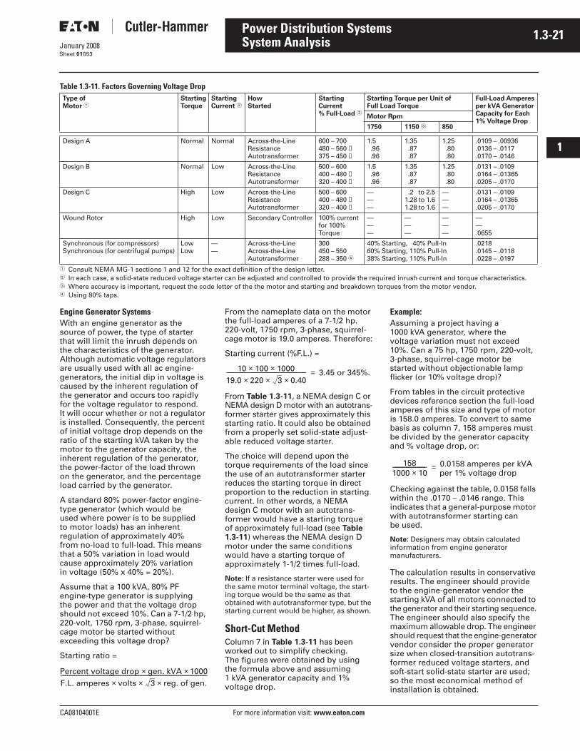
CA08104001E For more information visit: www.eaton.com
1.3-21January 2008
Power Distribution Systems
i
ii
1
2
3
4
5
6
7
8
9
10
11
12
13
14
15
16
17
18
19
20
21
Sheet 01
System Analysis053
Table 1.3-11. Factors Governing Voltage Drop
� Consult NEMA MG-1 sections 1 and 12 for the exact definition of the design letter.� In each case, a solid-state reduced voltage starter can be adjusted and controlled to provide the required inrush current and torque characteristics.� Where accuracy is important, request the code letter of the the motor and starting and breakdown torques from the motor vendor.� Using 80% taps.
Engine Generator SystemsWith an engine generator as the source of power, the type of starter that will limit the inrush depends on the characteristics of the generator. Although automatic voltage regulators are usually used with all ac engine-generators, the initial dip in voltage is caused by the inherent regulation of the generator and occurs too rapidly for the voltage regulator to respond. It will occur whether or not a regulator is installed. Consequently, the percent of initial voltage drop depends on the ratio of the starting kVA taken by the motor to the generator capacity, the inherent regulation of the generator, the power-factor of the load thrown on the generator, and the percentage load carried by the generator.
A standard 80% power-factor engine-type generator (which would be used where power is to be supplied to motor loads) has an inherent regulation of approximately 40% from no-load to full-load. This means that a 50% variation in load would cause approximately 20% variation in voltage (50% x 40% = 20%).
Assume that a 100 kVA, 80% PF engine-type generator is supplying the power and that the voltage drop should not exceed 10%. Can a 7-1/2 hp, 220-volt, 1750 rpm, 3-phase, squirrel-cage motor be started without exceeding this voltage drop?
Starting ratio =
From the nameplate data on the motor the full-load amperes of a 7-1/2 hp. 220-volt, 1750 rpm, 3-phase, squirrel-cage motor is 19.0 amperes. Therefore:
Starting current (%F.L.) =
From Table 1.3-11, a NEMA design C or NEMA design D motor with an autotrans-former starter gives approximately this starting ratio. It could also be obtained from a properly set solid-state adjust-able reduced voltage starter.
The choice will depend upon the torque requirements of the load since the use of an autotransformer starter reduces the starting torque in direct proportion to the reduction in starting current. In other words, a NEMA design C motor with an autotrans-former would have a starting torque of approximately full-load (see Table 1.3-11) whereas the NEMA design D motor under the same conditions would have a starting torque of approximately 1-1/2 times full-load.
Note: If a resistance starter were used for the same motor terminal voltage, the start-ing torque would be the same as that obtained with autotransformer type, but the starting current would be higher, as shown.
Short-Cut MethodColumn 7 in Table 1.3-11 has been worked out to simplify checking. The figures were obtained by using the formula above and assuming 1 kVA generator capacity and 1% voltage drop.
Example:Assuming a project having a 1000 kVA generator, where the voltage variation must not exceed 10%. Can a 75 hp, 1750 rpm, 220-volt, 3-phase, squirrel-cage motor be started without objectionable lamp flicker (or 10% voltage drop)?
From tables in the circuit protective devices reference section the full-load amperes of this size and type of motor is 158.0 amperes. To convert to same basis as column 7, 158 amperes must be divided by the generator capacity and % voltage drop, or:
Checking against the table, 0.0158 falls within the .0170 – .0146 range. Thisindicates that a general-purpose motor with autotransformer starting can be used.
Note: Designers may obtain calculated information from engine generator manufacturers.
The calculation results in conservative results. The engineer should provide to the engine-generator vendor the starting kVA of all motors connected to the generator and their starting sequence. The engineer should also specify the maximum allowable drop. The engineer should request that the engine-generator vendor consider the proper generator size when closed-transition autotrans-former reduced voltage starters, and soft-start solid-state starter are used; so the most economical method of installation is obtained.
Type of Motor �
StartingTorque
StartingCurrent �
HowStarted
StartingCurrent% Full-Load �
Starting Torque per Unit of Full Load Torque
Full-Load Amperesper kVA GeneratorCapacity for Each1% Voltage Drop
Motor Rpm
1750 1150 � 850
Design A Normal Normal Across-the-LineResistanceAutotransformer
600 – 700480 – 560 ➁375 – 450 ➁
1.5 .96 .96
1.35 .87 .87
1.25 .80 .80
.0109 – .00936
.0136 – .0117
.0170 – .0146
Design B Normal Low Across-the-LineResistanceAutotransformer
500 – 600400 – 480 ➁320 – 400 ➁
1.5 .96 .96
1.35 .87 .87
1.25 .80 .80
.0131 – .0109
.0164 – .01365
.0205 – .0170
Design C High Low Across-the-LineResistanceAutotransformer
500 – 600400 – 480 ➁320 – 400 ➁
———
.2 to 2.51.28 to 1.61.28 to 1.6
———
.0131 – .0109
.0164 – .01365
.0205 – .0170
Wound Rotor High Low Secondary Controller 100% currentfor 100%Torque
———
———
———
——.0655
Synchronous (for compressors)Synchronous (for centrifugal pumps)
LowLow
——
Across-the-LineAcross-the-LineAutotransformer
300450 – 550288 – 350 �
40% Starting, 40% Pull-In60% Starting, 110% Pull-In38% Starting, 110% Pull-In
.0218
.0145 – .0118
.0228 – .0197
Percent voltage drop gen. kVA× 1000×F.L. amperes volts× 3× reg. of gen.×−−−−−−−−−−−−−−−−−−−−−−−−−−−−−−−−−−−−−−−−−−−−−−−−−−−−−−−−−−−−−−−−−−
10 100× 1000×19.0 220× 3× 0.40×−−−−−−−−−−−−−−−−−−−−−−−−−−−−−−−−−−−− 3.45 or 345%.=
1581000 10×−−−−−−−−−−−−−−− 0.0158 amperes per kVA
per 1% voltage drop=
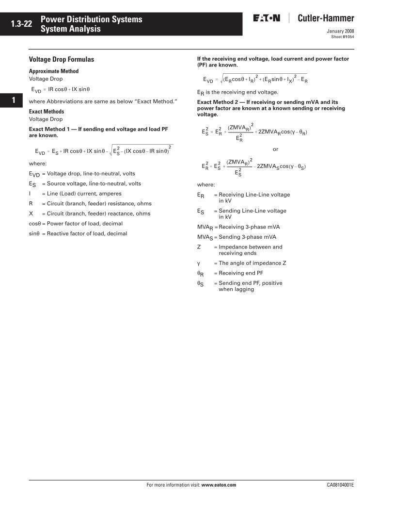
1.3-22
For more information visit: www.eaton.com CA08104001E
January 2008
Power Distribution Systems
i
ii
1
2
3
4
5
6
7
8
9
10
11
12
13
14
15
16
17
18
19
20
21
Sheet 01
System Analysis054
Voltage Drop Formulas
Approximate MethodVoltage Drop
where Abbreviations are same as below “Exact Method.”
Exact MethodsVoltage Drop
Exact Method 1 — If sending end voltage and load PF are known.
where:
EVD = Voltage drop, line-to-neutral, volts
ES = Source voltage, line-to-neutral, volts
I = Line (Load) current, amperes
R = Circuit (branch, feeder) resistance, ohms
X = Circuit (branch, feeder) reactance, ohms
cosθ = Power factor of load, decimal
sinθ = Reactive factor of load, decimal
If the receiving end voltage, load current and power factor (PF) are known.
ER is the receiving end voltage.
Exact Method 2 — If receiving or sending mVA and its power factor are known at a known sending or receiving voltage.
or
where:
ER = Receiving Line-Line voltage in kV
ES = Sending Line-Line voltage in kV
MVAR = Receiving 3-phase mVA
MVAS = Sending 3-phase mVA
Z = Impedance between andreceiving ends
γ = The angle of impedance Z
θR = Receiving end PF
θS = Sending end PF, positive when lagging
EVD IR cosθ IX sinθ+=
EVD ES IR cosθ IX sinθ ES2 IX cosθ IR sinθ–( )–
2–+ +=
EVD ERcosθ IR+( )2 ERsinθ IX+( )
2 ER–+=
ES2 ER
2 ZMVAR( )2
ER2
---------------------------------- 2ZMVARcos γ θR–( )+ +=
ER2 ES
2 ZMVAR( )2
ES2
---------------------------------- 2ZMVAScos γ θS–( )–+=
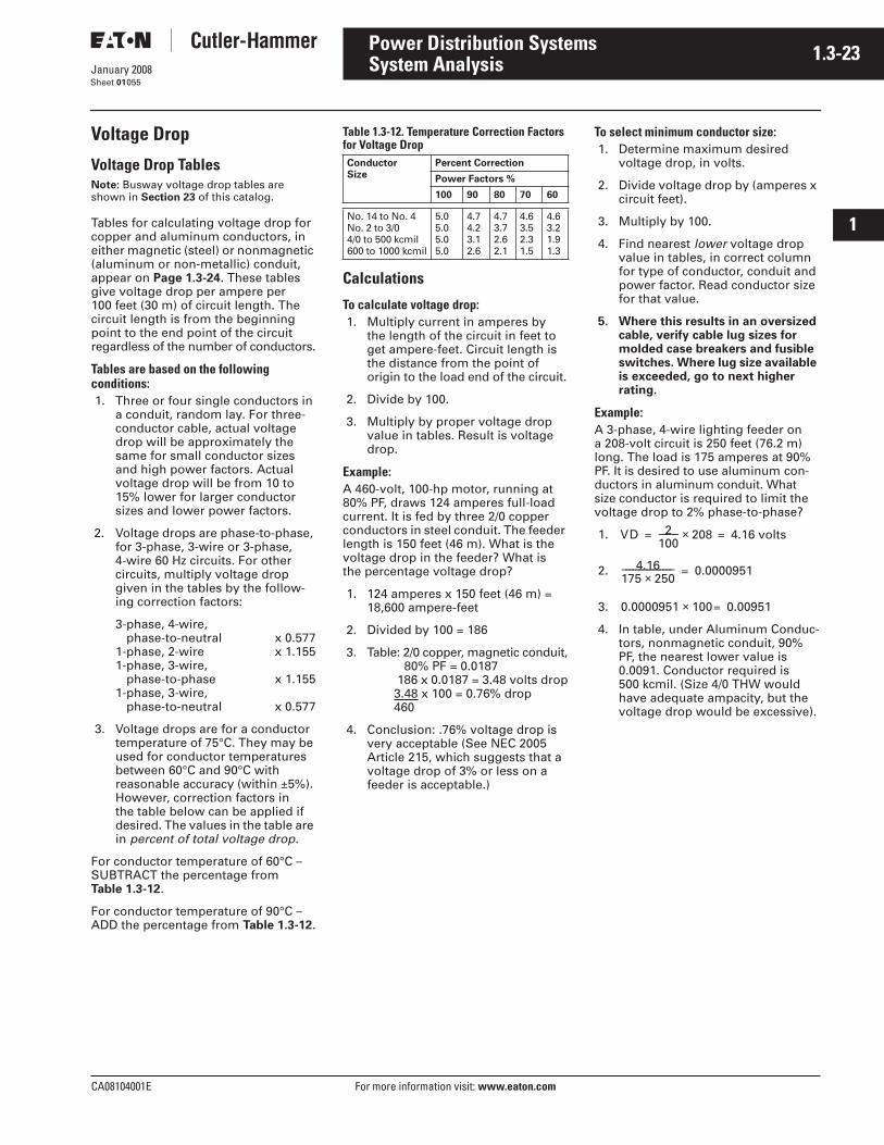
CA08104001E For more information visit: www.eaton.com
1.3-23January 2008
Power Distribution Systems
i
ii
1
2
3
4
5
6
7
8
9
10
11
12
13
14
15
16
17
18
19
20
21
Sheet 01
System Analysis055
Voltage Drop
Voltage Drop TablesNote: Busway voltage drop tables are shown in Section 23 of this catalog.
Tables for calculating voltage drop for copper and aluminum conductors, in either magnetic (steel) or nonmagnetic (aluminum or non-metallic) conduit, appear on Page 1.3-24. These tables give voltage drop per ampere per 100 feet (30 m) of circuit length. The circuit length is from the beginning point to the end point of the circuit regardless of the number of conductors.
Tables are based on the following conditions:1. Three or four single conductors in
a conduit, random lay. For three-conductor cable, actual voltage drop will be approximately the same for small conductor sizes and high power factors. Actual voltage drop will be from 10 to 15% lower for larger conductor sizes and lower power factors.
2. Voltage drops are phase-to-phase, for 3-phase, 3-wire or 3-phase, 4-wire 60 Hz circuits. For other circuits, multiply voltage drop given in the tables by the follow-ing correction factors:
3-phase, 4-wire, phase-to-neutral x 0.577
1-phase, 2-wire x 1.1551-phase, 3-wire,
phase-to-phase x 1.1551-phase, 3-wire,
phase-to-neutral x 0.577
3. Voltage drops are for a conductor temperature of 75°C. They may be used for conductor temperatures between 60°C and 90°C with reasonable accuracy (within ±5%). However, correction factors in the table below can be applied if desired. The values in the table are in percent of total voltage drop.
For conductor temperature of 60°C – SUBTRACT the percentage from Table 1.3-12.
For conductor temperature of 90°C – ADD the percentage from Table 1.3-12.
Table 1.3-12. Temperature Correction Factors for Voltage Drop
Calculations
To calculate voltage drop:1. Multiply current in amperes by
the length of the circuit in feet to get ampere-feet. Circuit length is the distance from the point of origin to the load end of the circuit.
2. Divide by 100.
3. Multiply by proper voltage drop value in tables. Result is voltage drop.
Example:A 460-volt, 100-hp motor, running at 80% PF, draws 124 amperes full-load current. It is fed by three 2/0 copper conductors in steel conduit. The feeder length is 150 feet (46 m). What is the voltage drop in the feeder? What is the percentage voltage drop?
1. 124 amperes x 150 feet (46 m) = 18,600 ampere-feet
2. Divided by 100 = 186
3. Table: 2/0 copper, magnetic conduit, 80% PF = 0.0187 186 x 0.0187 = 3.48 volts drop3.48 x 100 = 0.76% drop460
4. Conclusion: .76% voltage drop is very acceptable (See NEC 2005 Article 215, which suggests that a voltage drop of 3% or less on a feeder is acceptable.)
To select minimum conductor size:1. Determine maximum desired
voltage drop, in volts.
2. Divide voltage drop by (amperes x circuit feet).
3. Multiply by 100.
4. Find nearest lower voltage drop value in tables, in correct column for type of conductor, conduit and power factor. Read conductor size for that value.
5. Where this results in an oversized cable, verify cable lug sizes for molded case breakers and fusible switches. Where lug size available is exceeded, go to next higher rating.
Example:A 3-phase, 4-wire lighting feeder on a 208-volt circuit is 250 feet (76.2 m) long. The load is 175 amperes at 90% PF. It is desired to use aluminum con-ductors in aluminum conduit. What size conductor is required to limit the voltage drop to 2% phase-to-phase?
1.
2.
3.
4. In table, under Aluminum Conduc-tors, nonmagnetic conduit, 90% PF, the nearest lower value is 0.0091. Conductor required is 500 kcmil. (Size 4/0 THW would have adequate ampacity, but the voltage drop would be excessive).
ConductorSize
Percent Correction
Power Factors %
100 90 80 70 60
No. 14 to No. 4No. 2 to 3/04/0 to 500 kcmil600 to 1000 kcmil
5.05.05.05.0
4.74.23.12.6
4.73.72.62.1
4.63.52.31.5
4.63.21.91.3
VD 2100−−−−−− 208 4.16 volts=×=
4.16175 250×−−−−−−−−−−−−−−− 0.0000951=
0.0000951 100 0.00951=×
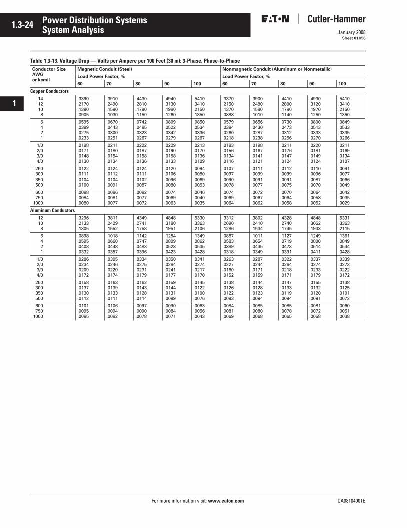
1.3-24
For more information visit: www.eaton.com CA08104001E
January 2008
Power Distribution Systems
i
ii
1
2
3
4
5
6
7
8
9
10
11
12
13
14
15
16
17
18
19
20
21
Sheet 01
System Analysis056
Table 1.3-13. Voltage Drop — Volts per Ampere per 100 Feet (30 m); 3-Phase, Phase-to-PhaseConductor Size AWGor kcmil
Magnetic Conduit (Steel) Nonmagnetic Conduit (Aluminum or Nonmetallic)
Load Power Factor, % Load Power Factor, %
60 70 80 90 100 60 70 80 90 100
Copper Conductors1412108
.3390
.2170
.1390
.0905
.3910
.2490
.1590
.1030
.4430
.2810
.1790
.1150
.4940
.3130
.1980
.1260
.5410
.3410
.2150
.1350
.3370
.2150
.1370
.0888
.3900
.2480
.1580
.1010
.4410
.2800
.1780
.1140
.4930
.3120
.1970
.1250
.5410
.3410
.2150
.1350
6421
.0595
.0399
.0275
.0233
.0670
.0443
.0300
.0251
.0742
.0485
.0323
.0267
.0809
.0522
.0342
.0279
.0850
.0534
.0336
.0267
.0579
.0384
.0260
.0218
.0656
.0430
.0287
.0238
.0730
.0473
.0312
.0256
.0800
.0513
.0333
.0270
.0849
.0533
.0335
.0266
1/02/03/04/0
.0198
.0171
.0148
.0130
.0211
.0180
.0154
.0134
.0222
.0187
.0158
.0136
.0229
.0190
.0158
.0133
.0213
.0170
.0136
.0109
.0183
.0156
.0134
.0116
.0198
.0167
.0141
.0121
.0211
.0176
.0147
.0124
.0220
.0181
.0149
.0124
.0211
.0169
.0134
.0107
250300350500
.0122
.0111
.0104
.0100
.0124
.0112
.0104
.0091
.0124
.0111
.0102
.0087
.0120
.0106
.0096
.0080
.0094
.0080
.0069
.0053
.0107
.0097
.0090
.0078
.0111
.0099
.0091
.0077
.0112
.0099
.0091
.0075
.0110
.0096
.0087
.0070
.0091
.0077
.0066
.0049
600750
1000
.0088
.0084
.0080
.0086
.0081
.0077
.0082
.0077
.0072
.0074
.0069
.0063
.0046
.0040
.0035
.0074
.0069
.0064
.0072
.0067
.0062
.0070
.0064
.0058
.0064
.0058
.0052
.0042
.0035
.0029
Aluminum Conductors12108
.3296
.2133
.1305
.3811
.2429
.1552
.4349
.2741
.1758
.4848
.3180
.1951
.5330
.3363
.2106
.3312
.2090
.1286
.3802
.2410
.1534
.4328
.2740
.1745
.4848
.3052
.1933
.5331
.3363
.2115
6421
.0898
.0595
.0403
.0332
.1018
.0660
.0443
.0357
.1142
.0747
.0483
.0396
.1254
.0809
.0523
.0423
.1349
.0862
.0535
.0428
.0887
.0583
.0389
.0318
.1011
.0654
.0435
.0349
.1127
.0719
.0473
.0391
.1249
.0800
.0514
.0411
.1361
.0849
.0544
.0428
1/02/03/04/0
.0286
.0234
.0209
.0172
.0305
.0246
.0220
.0174
.0334
.0275
.0231
.0179
.0350
.0284
.0241
.0177
.0341
.0274
.0217
.0170
.0263
.0227
.0160
.0152
.0287
.0244
.0171
.0159
.0322
.0264
.0218
.0171
.0337
.0274
.0233
.0179
.0339
.0273
.0222
.0172
250300350500
.0158
.0137
.0130
.0112
.0163
.0139
.0133
.0111
.0162
.0143
.0128
.0114
.0159
.0144
.0131
.0099
.0145
.0122
.0100
.0076
.0138
.0126
.0122
.0093
.0144
.0128
.0123
.0094
.0147
.0133
.0119
.0094
.0155
.0132
.0120
.0091
.0138
.0125
.0101
.0072
600750
1000
.0101
.0095
.0085
.0106
.0094
.0082
.0097
.0090
.0078
.0090
.0084
.0071
.0063
.0056
.0043
.0084
.0081
.0069
.0085
.0080
.0068
.0085
.0078
.0065
.0081
.0072
.0058
.0060
.0051
.0038
CA08104001E For more information visit: www.eaton.com
1.4-1January 2008
Power Distribution Systems
i
ii
1
2
3
4
5
6
7
8
9
10
11
12
13
14
15
16
17
18
19
20
21
Sheet 01
System Application ConsiderationsCapacitors
057
Capacitors and Power Factor
Capacitor General Application ConsiderationsAdditional application information is available in Section 37 regarding capacitors and harmonic filters as follows:
■ Capacitor selection.■ Where to install capacitors in a plant
distribution system.■ Locating capacitors on reduced
voltage and multi-speed starters.■ Harmonic considerations.■ Eliminating harmonic problems.■ National Electrical Code
requirements.
Medium Voltage Capacitor SwitchingCapacitance switching constitutes severe operating duty for a circuit breaker. At the time the breaker opens at near current zero the capacitor is fully charged. After interruption, when the alternating voltage on the source side of the breaker reaches its opposite maximum, the voltage that appears across the contacts of the open breaker is at least twice the normal peak line-to-neutral voltage of the circuit. If a breakdown occurs across the open contact the arc is reestablished. Due to the circuit constants on the supply side of the breaker, the voltage across the open contact can reach three times the normal line-to-neutral voltage. After it is interrupted and with subsequent alternation of the supply side voltage, the voltage across the open contact is even higher.
ANSI Standard C37.06 (indoor oilless circuit breakers) indicates the preferred ratings of Eaton’s Cutler-Hammer Type VCP-W vacuum breaker. For capacitor switching careful attention should be paid to the notes accompanying the table. The definition of the terms are in ANSI Standard C37.04 Article 5.13 (for the latest edition). The application guide ANSI/IEEE Standard C37.012 covers the method of calculation of the quantities covered by C37.06 Standard.
Note that the definitions in C37.04 make the switching of two capacitors banks in close proximity to the switch-gear bus a back-to-back mode of switching. This classification requires a definite purpose circuit breaker (breakers specifically designed for capacitance switching).
We recommend that such application be referred to Eaton.
A breaker specified for capacitor switching should include as applicable:
1. Rated maximum voltage.
2. Rated frequency.
3. Rated open wire line charging switching current.
4. Rated isolated cable charging and shunt capacitor switching current.
5. Rated back-to-back cable charging and back-to-back capacitor switch-ing current.
6. Rated transient overvoltage factor.
7. Rated transient inrush current and its frequency.
8. Rated interrupting time.
9. Rated capacitive current switching life.
10. Grounding of system and capacitor bank.
Loadbreak interrupter switches are permitted by ANSI/IEEE Standard C37.30 to switch capacitance but they must have tested ratings for the purpose. Refer to Cutler-Hammer Type MVS ratings.
Low Voltage Capacitor SwitchingCircuit breakers and switches for use with a capacitor must have a current rating in excess of rated capacitor current to provide for overcurrent from overvoltages at fundamental frequency and harmonic currents. The following percent of the capacitor-rated current should be used as a general guideline:
Fused and unfused switches. . . . 165%
Molded case breaker or equivalent . . . . . . . . . . . . . . . . . 150%
DSII power circuit breakers. . . . . 135%
Magnum DS power circuit breaker . . . . . . . . . . . . . . 135%
Contactors:Open type . . . . . . . . . . . . . . . . . . . 135%
Enclosed type . . . . . . . . . . . . . . . . 150%
The NEC, Section 460-8(c), requires the disconnecting means to be rated not less than 135% of the rated capacitor current (for 600 V and below).
See Section 37 for switching device ampere ratings. They are based on percentage of capacitor-rated current as indicated (above). The interrupting rating of the switch must be selected to match the system fault current available at the point of capacitor appli-cation. Whenever a capacitor bank is purchased with less than the ultimate kvar capacity of the rack or enclosure, the switch rating should be selected based on the ultimate kvar capacity — not the initial installed capacity.
Refer to Section 37 for recommended selection of capacitor switching devices; recommended maximum capacitor ratings for various motor types and voltages; and for required multipliers to determine capacitor kvars required for Power Factor Correction.
1.4-2
For more information visit: www.eaton.com CA08104001E
January 2008
Power Distribution Systems
i
ii
1
2
3
4
5
6
7
8
9
10
11
12
13
14
15
16
17
18
19
20
21
Sheet 01
System Application ConsiderationsCapacitors
058
Motor Power Factor CorrectionSee Section 37 containing suggested maximum capacitor ratings for induction motors switched with the capacitor. The data is general in nature and representative of general purpose induction motors of standard design. The preferable means to select capaci-tor ratings is based on the “maximum recommended kvar” information available from the motor manufacturer. If this is not possible or feasible, the tables can be used.
An important point to remember is that if the capacitor used with the motor is too large, self-excitation may cause a motor-damaging overvoltage when the motor and capacitor combi-nation is disconnected from the line. In addition, high transient torques capable of damaging the motor shaft or coupling can occur if the motor is reconnected to the line while rotating and still generating a voltage of self-excitation.
Definitionskvar — rating of the capacitor in reactive kilovolt-amperes. This value is approximately equal to the motor no-load magnetizing kilovars.
% AR — percent reduction in line current due to the capacitor. A capacitor located on the motor side of the overload relay reduces line current through the relay. Therefore, a different overload relay and/or setting may be necessary. The reduc-tion in line current may be determined by measuring line current with and without the capacitor or by calculation as follows:
If a capacitor is used with a lower kvar rating than listed in tables, the % AR can be calculated as follows:
The tables can also be used for other motor ratings as follows:
A. For standard 60 Hz motors operating at 50 Hz:
kvar = 1.7 – 1.4 of kvar listed% AR= 1.8 – 1.35 of % AR listed
B. For standard 50 Hz motors operating at 50 Hz:
kvar = 1.4 – 1.1 of kvar listed% AR= 1.4 – 1.05 of % AR listed
C. For standard 60 Hz wound-rotor motors:
kvar = 1.1 of kvar listed% AR= 1.05 of % AR listed
Note: For A, B, C, the larger multipliers apply for motors of higher speeds; i.e., 3600 rpm = 1.7 mult., 1800 rpm = 1.65 mult., etc.
To derate a capacitor used on a system voltage lower than the capacitor volt-age rating, such as a 240-volt capacitor used on a 208-volt system, use the following formula:
For the kVAC required to correct the power factor from a given value of COS φ1 to COS φ2, the formula is:
kVAC = KW (tan phase1 – tan phase2)
Capacitors cause a voltage rise. At light load periods the capacitive voltage rise can raise the voltage at the location of the capacitors to an unacceptable level. This voltage rise can be calculated approximately by the formula
MVAR is the capacitor rating and MVASC is the system short circuit capacity.
With the introduction of variable speed drives and other harmonic current generating loads, the capacitor imped-ance value determined must not be resonant with the inductive reactances of the system.
% AR 100 100 (Original PF)(Improved PF)−−−−−−−−−−−−−−−−−−−−−−−−×–=
% AR Listed % AR Actual kvarkvar in Table−−−−−−−−−−−−−−−−−−−−−−×=
Actual kvar =
Nameplate kvar Applied Voltage( )2
Nameplate Voltage( )2----------------------------------------------------------------------×
% VRMVAr
MVASC−−−−−−−−−−−−=
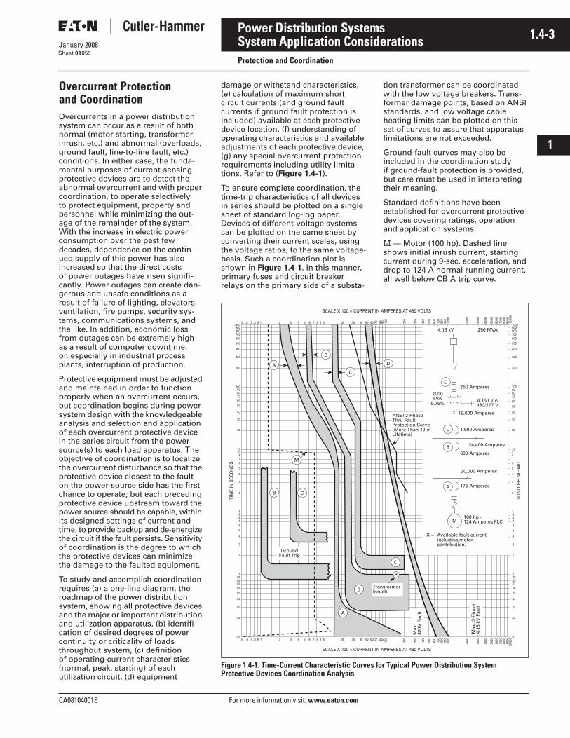
CA08104001E For more information visit: www.eaton.com
1.4-3January 2008
Power Distribution Systems
i
ii
1
2
3
4
5
6
7
8
9
10
11
12
13
14
15
16
17
18
19
20
21
Sheet 01
System Application ConsiderationsProtection and Coordination
059
Overcurrent Protection and CoordinationOvercurrents in a power distribution system can occur as a result of both normal (motor starting, transformer inrush, etc.) and abnormal (overloads, ground fault, line-to-line fault, etc.) conditions. In either case, the funda-mental purposes of current-sensing protective devices are to detect the abnormal overcurrent and with proper coordination, to operate selectively to protect equipment, property and personnel while minimizing the out-age of the remainder of the system. With the increase in electric power consumption over the past few decades, dependence on the contin-ued supply of this power has also increased so that the direct costs of power outages have risen signifi-cantly. Power outages can create dan-gerous and unsafe conditions as a result of failure of lighting, elevators, ventilation, fire pumps, security sys-tems, communications systems, and the like. In addition, economic loss from outages can be extremely high as a result of computer downtime, or, especially in industrial process plants, interruption of production.
Protective equipment must be adjusted and maintained in order to function properly when an overcurrent occurs, but coordination begins during power system design with the knowledgeable analysis and selection and application of each overcurrent protective device in the series circuit from the power source(s) to each load apparatus. The objective of coordination is to localize the overcurrent disturbance so that the protective device closest to the fault on the power-source side has the first chance to operate; but each preceding protective device upstream toward the power source should be capable, within its designed settings of current and time, to provide backup and de-energize the circuit if the fault persists. Sensitivity of coordination is the degree to which the protective devices can minimize the damage to the faulted equipment.
To study and accomplish coordination requires (a) a one-line diagram, the roadmap of the power distribution system, showing all protective devices and the major or important distribution and utilization apparatus, (b) identifi-cation of desired degrees of power continuity or criticality of loads throughout system, (c) definition of operating-current characteristics (normal, peak, starting) of each utilization circuit, (d) equipment
damage or withstand characteristics, (e) calculation of maximum short circuit currents (and ground fault currents if ground fault protection is included) available at each protective device location, (f) understanding of operating characteristics and available adjustments of each protective device, (g) any special overcurrent protection requirements including utility limita-tions. Refer to (Figure 1.4-1).
To ensure complete coordination, the time-trip characteristics of all devices in series should be plotted on a single sheet of standard log-log paper. Devices of different-voltage systems can be plotted on the same sheet by converting their current scales, using the voltage ratios, to the same voltage-basis. Such a coordination plot is shown in Figure 1.4-1. In this manner, primary fuses and circuit breaker relays on the primary side of a substa-
tion transformer can be coordinated with the low voltage breakers. Trans-former damage points, based on ANSI standards, and low voltage cableheating limits can be plotted on this set of curves to assure that apparatus limitations are not exceeded.
Ground-fault curves may also be included in the coordination study if ground-fault protection is provided, but care must be used in interpreting their meaning.
Standard definitions have been established for overcurrent protective devices covering ratings, operation and application systems.
M — Motor (100 hp). Dashed line shows initial inrush current, starting current during 9-sec. acceleration, and drop to 124 A normal running current, all well below CB A trip curve.
Figure 1.4-1. Time-Current Characteristic Curves for Typical Power Distribution System Protective Devices Coordination Analysis
1000
109
76
.9
4
5
.5
.3
.2
10090
30
20
500
300
200
10,0
00
8000
6000
9000
7000
5000
4000
3000
2000
1000
800
600
900
700
500
400
300
200
100
8060 907050403020109875 6431 2.9.8.7.5 .6
600
900800700
400
40
8
50
80
6070
3
1
2
.8
.7
.6
.4
.1.09.08.07.06
.05
.04
.03
.02
.01
10,0
00
8000
6000
9000
7000
5000
4000
3000
2000
1000800
600
900
700
500
400
300
200
1008060 907050403020109875 6431 2.9.8.7.5 .6
1000
109
76
.9
4
5
.5
.3
.2
10090
30
20
500
300
200
600
900800700
400
40
8
50
80
6070
3
1
2
.8
.7
.6
.4
.1
.09
.08
.07
.06
.05
.04
.03
.02
.01
TIME IN
SEC
ON
DS
SCALE X 100 = CURRENT IN AMPERES AT 480 VOLTS
SCALE X 100 = CURRENT IN AMPERES AT 480 VOLTS
TIM
E IN
SEC
ON
DS
250 MVA4.16 kV
250 Amperes1000kVA
5.75%4,160 V ∆480/277 V
19,600 Amperes
1,600 Amperes
24,400 Amperes
600 Amperes
D
C
B
A
M
20,000 Amperes
175 Amperes
100 hp –124 Amperes FLC
X = Available fault currentincluding motorcontribution.
D
ANSI 3-PhaseThru FaultProtection Curve(More Than 10 inLifetime)
C
B
A
CB
A
B
C
TransformerInrush
GroundFault Trip
Max
.48
0V F
ault
Max
. 3-P
has
e4.
16 k
V F
ault
M
1.4-4
For more information visit: www.eaton.com CA08104001E
January 2008
Power Distribution Systems
i
ii
1
2
3
4
5
6
7
8
9
10
11
12
13
14
15
16
17
18
19
20
21
Sheet 01
System Application ConsiderationsProtection and Coordination
060
A — CB (175 A) coordinates selectively with motor M on starting and running and with all upstream devices, except that CB B will trip first on low level ground faults.
B — CB (600 A) coordinates selectively with all upstream and downstream devices, except will trip before A on limited ground faults, since A has no ground fault trips.
C — Main CB (1600 A) coordinates selectively with all downstream devices and with primary fuse D, for all faults on load side of CB.
D — Primary fuse (250 A, 4,160 V) coordinates selectively with all secondary protective devices. Curve converted to 480 V basis. Clears trans-former inrush point (12 x FLC for 0.1 sec.), indicating that fuse will not blow on inrush. Fuse is underneath right-half of ANSI 3-phase withstand curve, indicat-ing fuse will protect transformer for high-magnitude faults up to ANSI rating.
Delta-Wye secondary side short circuit is not reflected to the primary by the relation
for L-L and L-G faults. For line-to-line fault the secondary (low voltage) side fault current is 0.866 x I 3-phase fault current.
However the primary (high voltage) side fault is the same as if the secondary fault was a 3-phase fault. Therefore in coordination studies, the knee of the short-time pickup setting on the sec-ondary breaker should be multiplied by
before it is compared to the minimum melting time of the upstream primary fuse curve. In the example shown, the knee is at 4000 amperes 30 sec., and the 30-sec. trip time should be com-pared to the MMT (minimum melt time) of the fuse curve at 4000 x 1.1547 = 4619 amperes. In this case there is adequate clearance to the fuse curve.
In the example shown, the ANSI 3-phase through fault protection curve must be multiplied by 0.577 and replotted in order to determine the protection given by the primary for a single line to ground fault in the secondary.
Maximum 480 V 3-phase fault indicated on the horizontal current axis.
Maximum 4160 V 3-phase fault indicated, converted to 480 V basis.
The ANSI protection curves are speci-fied in ANSI C57.109 for liquid-filled transformers and C57.12.59 for dry-type transformers.
Illustrative examples such as shown here start the coordination study from the lowest rated device proceeding upstream. In practice the setting or rating of the utility’s protective device sets the upper limit. Even in cases where the customer owns the medium voltage or higher distribution system, the setting or rating of the lowest set protective device at the source deter-mines the settings of the downstream devices and the coordination.
Therefore the coordination study should start at the present setting or rating of the upstream device and work towards the lowest rated device. If this procedure results in unaccept-able settings, the setting or rating of the upstream device should be reviewed. Where the utility is the sole source they should be consulted. Where the owner has its own medium or higher voltage distribution the set-tings or ratings of all upstream devices should be checked.
If perfect coordination is not feasible, then lack of coordination should be limited to the smallest part of the system.
Application data is available for all pro-tective equipment to permit systems to be designed for adequate overcurrent protection and coordination. For circuit breakers of all types, time-current curves permit selection of instantaneous and inverse-time trips. For more complex cir-cuit breakers, with solid state trip units, trip curves include long- and short-time delays, as well as ground-fault tripping, with a wide range of settings and fea-tures to provide selectivity and coordina-tion. For current-limiting circuit breakers, fuses, and circuit breakers with integral fuses, not only are time-current charac-teristic curves available, but also data on current-limiting per-formance and protection for downstream devices.
In a fully rated system, all circuit break-ers must have an interrupting capacity adequate for the maximum available fault current at their point of applica-tion. All breakers are equipped with long-time-delay (and possibly short delay) and instantaneous overcurrent trip devices. A main breaker may have short time-delay tripping to allow a feeder breaker to isolate the fault while power is maintained to all the remaining feeders.
A selective or fully coordinated system permits maximum service continuity. The tripping characteristics of each overcurrent device in the system must be selected and set so that the breaker nearest the fault opens to isolate the faulted circuit, while all other breakers remain closed, continuing power to the entire unfaulted part of the system.
The 2005 National Electrical Code � (NEC) has added specific requirements for designing certain circuits with selective coordination. Article 100 has added, under Coordination (Selective), the following definition: “Localization of an overcurrent condi-tion to restrict outages to the circuit or equipment affected, accomplished by the choice of overcurrent protective devices and their ratings or settings.”� NEC 2005 NFPA 70: National Electrical Code
International Electrical Code Series.
Article 620.62 (Elevators, Dumbwait-ers, Escalators, Moving Walks, Wheelchair Lifts, and Stairway Chair Lifts) requires “Where more than one driving machine disconnecting means is supplied by a single feeder, the over-current protective devices in each dis-connecting means shall be selectively coordinated with any other supply side overcurrent protective device.” A similar requirement under Article 700.27 is as follows; “Emergency system(s) overcurrent devices shall be selectively coordinated with all supply side overcurrent protective devices.” Also Article 701.18, added “Legally required standby system(s) overcurrent devices shall be selec-tively coordinated with all supply side overcurrent devices.”
In addition, for health care facilities, Article 517.26, Application of Other Articles requires that “The essential electrical system shall meet the requirements of Article 700, except as amended by Article 517.”
IPVS
VP−−−− IS×=
10.866−−−−−−−−− or 1.1547
I480V
I4160V
4160480
−−−−−−−− ×=
CA08104001E For more information visit: www.eaton.com
1.4-5January 2008
Power Distribution Systems
i
ii
1
2
3
4
5
6
7
8
9
10
11
12
13
14
15
16
17
18
19
20
21
Sheet 01
System Application ConsiderationsProtection and Coordination
061
All breakers must have an interrupting capacity not less than the maximum available short circuit current at their point of application. A selective system is a fully rated system with tripping devices chosen and adjusted to provide the desired selectivity. The tripping characteristics of each overcurrent device should not overlap, but should maintain a minimum time interval for devices in series (to allow for normal operating tolerances) at all current values. Generally, a maximum of four low voltage circuit breakers can be operated selectively in series, with the feeder or branch breaker down-stream furthest from the source.
Specify true rms sensing devices in order to avoid false trips due to rapid currents or spikes. Specify tripping elements with I2t or I4t feature for improved coordination with other devices having I2t or I4t (such as OPTIM� trip units) characteristics, and fuses.
In general for systems such as shown in the example:
1. The settings or ratings of the pri-mary side fuse and main breaker must not exceed the settings allowed by NEC Article 450.
2. At 12 x IFL the minimum melting time characteristic of the fuse should be higher than 0.1 second.
3.
4. The primary fuse should be to the left of the transformer damage curve as much as possible. The correction factor for a single line-to-ground factor must be applied to the damage curve.
5. The setting of the short-time delay element must be checked against the fuse MMT after it is corrected for line-to-line faults.
6. The maximum fault current must be indicated at the load side of each protective device.
7. The setting of a feeder protective device must comply with Article 240 and Article 430 of the NEC. It also must allow the starting and acceleration of the largest motor on the feeder while carrying all the other loads on the feeder.
Protection of Conductors(Excerpts from NEC 240.4)Conductors, other than flexible cords and fixture wires, shall be protected against overcurrent in accordance with their ampacities as specified in Section 310-15, unless otherwise permitted or required in (A) through (G).
A. Power Loss Hazard. Conductor overload protection shall not be required where the interruption of the circuit would create a hazard, such as in a material handling magnet circuit or fire pump circuit. Short circuit protection shall be provided.
Note: FPN See NFPA 20-2003, standard for the Installation of Stationary Pumps for Fire Protection.
B. Devices Rated 800 Amperes or Less. The next higher standard overcurrent device rating (above the ampacity of the conductors being protected) shall be permit-ted to be used, provided all of the following conditions are met.
1. The conductors being protected are not part of a multi-outlet branch circuit supplying recepta-cles for cord- and plug-connected portable loads.
2. The ampacity of the conductors does not correspond with the standard ampere rating of a fuse or a circuit breaker without overload trip adjustments above its rating (but that shall be permitted to have other trip or rating adjustments).
3. The next higher standard rating selected does not exceed 800 amperes.
C. Devices Rated Over 800 Amperes.Where the overcurrent device is rated over 800 amperes, the ampacity of the conductors it pro-tects shall be equal to or greater than the rating of the overcurrent device as defined in Section 240.6.
D. Small Conductors. Unless specifi-cally permitted in 240.4(E) or 240.4(G), the overcurrent protec-tion shall not exceed 15 amperes for 14 AWG, 20 amperes for 12 AWG, and 30 amperes for 10 AWG copper; or 15 amperes for 12 AWG and 25 amperes for 10 AWG alu-minum and copper-clad aluminum after any correction factors for ambient temperature and number of conductors have been applied.
E. Tap Conductors. Tap conductors shall be permitted to be protected against overcurrent in accordance with the following:
1. 210-19(A)(3) and (A)(4) Household Ranges and Cooking Appliances and Other Loads.
2. 240.5(B)(2) Fixture Wire.
3. 240.21 Location in Circuit.
4. 368.17(B) Reduction in Ampacity Size of Busway.
5. 368.17(C) Feeder or Branch Circuits (busway taps).
6. 430.53(D) Single Motor Taps.
Circuit Breaker Cable Temperature RatingsUL listed circuit breakers rated 125 A or less shall be marked as being suit-able for 60ºC (140ºF), 75ºC (167ºF) only or 60/75ºC (140/167ºF) wire. All Cutler-Hammer breakers rated 125 A or less are marked 60/75ºC. All UL listed circuit
breakers rated over 125 A are suitable for 75ºC conductors. Conductors rated for higher temperatures may be used, but must not be loaded to carry more current than the 75ºC ampacity of that size conductor for equipment marked or rated 75ºC or the 65ºC ampacity of that size conductor for equipment marked or rated 65ºC. However, when applying derated factors, so long as the actual load does not exceed the lower of the derated ampacity or the 75ºC or 60ºC ampacity that applies.
Zone Selective InterlockingTrip elements equipped with zone selective interlocking, trip without intentional time delay unless a restraint signal is received from a protective device downstream. Breakers equipped with this feature reduce the damage at the point of fault if the fault occurs at a location between the zone of protection.
The upstream breaker upon receipt of the restraint signal will not trip until its time-delay setting times out. If the breaker immediately downstream of the fault does not open, then after timing out, the upstream breaker will trip.
Breakers equipped with ground fault trip elements should also be specified to include zone interlocking for the ground fault trip element.
1.4-6
For more information visit: www.eaton.com CA08104001E
January 2008
Power Distribution Systems
i
ii
1
2
3
4
5
6
7
8
9
10
11
12
13
14
15
16
17
18
19
20
21
Sheet 01
System Application ConsiderationsProtection and Coordination
062
Ground Fault ProtectionArticle 230-95 of NEC requires ground-fault protection of equipment shall be provided for solidly grounded wye electrical services of more than 150 volts to ground, but not exceeding 600 volts phase-to-phase for each service disconnect rated 1000 amperes or more.
The rating of the service disconnect shall be considered to be the rating of the largest fuse that can be installed or the highest continuous current trip setting for which the actual overcurrent device installed in a circuit breaker is rated or can be adjusted.
The maximum allowable settings are: 1200 amperes pickup, 1 second or less trip delay at currents of 3000 amperes or greater.
The characteristics of the ground-fault trip elements create coordination problems with downstream devices not equipped with ground fault protection. The National Electrical Code exempts fire pumps and contin-uous industrial processes from this requirement.
It is recommended that in solidly grounded 480/277-volt systems where main breakers are specified to be equipped with ground fault trip elements that the feeder breakers be specified to be equipped with ground fault trip elements as well.
Suggested Ground Fault SettingsFor the main devices:A ground fault pickup setting equal to 20 – 30% of the main breaker rating but not to exceed 1200 amperes, and a time delay equal to the delay of the short time element, but not to exceed 1 second.
For the feeder ground fault setting:A setting equal to 20 – 30% of the feeder ampacity and a time delay to coordinate with the setting of the main (at least 6 cycles below the main).
If the desire to selectively coordinate ground fault devices results in settings which do not offer adequate damage protection against arcing single line-ground faults, the design engineer should decide between coordination and damage limitation.
For low voltage systems with high-magnitude available short circuit currents, common in urban areas and large industrial installations, several solutions are available. High interrupt-ing Series C� molded case breakers, current-limiting circuit breakers, or current-limiting fuses, limiters integral with molded-case circuit breakers (TRI-PAC�) or mounted on power cir-cuit breakers (MDSL) can be used to handle these large fault currents. To provide current limiting, these devices must clear the fault completely within the first half-cycle, limiting the peak current (Ip) and heat energy (I2t) let-through to considerably less than what would have occurred without the device. For a fully fusible system, rule-of-thumb fuse ratios or more accu-rate I2t curves can be used to provide selectivity and coordination. For fuse-breaker combinations, the fuse should be selected (coordinated) so as to per-mit the breaker to handle those over-loads and faults within its capacity; the fuse should operate before or with the breaker only on large faults, approaching the interrupting capacity of the breaker, to minimize fuse blowing. Recently, unfused, truly current-limiting circuit breakers with interrupting ratings adequate for the largest systems (Type Series C, FDC, JDC, KDC, LDC and NDC frames or Type Current Limit-R�) have become available.
Any of these current-limiting devices — fuses, fused breakers, or current-limiting breakers — cannot only clear these large faults safely, but also will limit the Ip and I2t let-through signifi-cantly to prevent damage to apparatus downstream, extending their zone of protection. Without the current limita-tion of the upstream device, the fault current could exceed the withstand capability of the downstream equip-ment. Underwriters Laboratories tests and lists these series combinations. Application information is available for combinations which have been tested and UL�-listed for safe operation downstream from MDSL, TRI-PAC, and Current Limit-R, or Series C breakers of various ratings, under high available fault currents.
Protective devices in electrical distri-bution systems may be properly coor-dinated when the systems are designed and built, but that is no guarantee that they will remain coordinated. System changes and additions, plus power source changes, frequently modify the protection requirements, sometimes causing loss of coordination and even increasing fault currents beyond the ratings of some devices. Consequently, periodic study of protective-device settings and ratings is as important for safety and preventing power outages as is periodic maintenance of the distribution system.
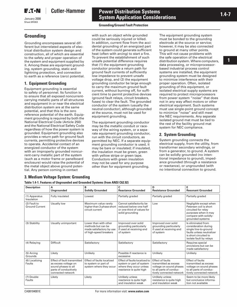
CA08104001E For more information visit: www.eaton.com
1.4-7January 2008
Power Distribution Systems
i
ii
1
2
3
4
5
6
7
8
9
10
11
12
13
14
15
16
17
18
19
20
21
Sheet 01
System Application ConsiderationsGrounding/Ground Fault Protection
063
GroundingGrounding encompasses several dif-ferent but interrelated aspects of elec-trical distribution system design and construction, all of which are essential to the safety and proper operation of the system and equipment supplied by it. Among these are equipment ground-ing, system grounding, static and lightning protection, and connection to earth as a reference (zero) potential.
1. Equipment GroundingEquipment grounding is essential to safety of personnel. Its function is to ensure that all exposed noncurrent-carrying metallic parts of all structures and equipment in or near the electrical distribution system are at the same potential, and that this is the zero reference potential of the earth. Equip-ment grounding is required by both the National Electrical Code (Article 250) and the National Electrical Safety Code regardless of how the power system is grounded. Equipment grounding also provides a return path for ground fault currents, permitting protective devices to operate. Accidental contact of an energized conductor of the system with an improperly grounded noncur-rent-carry metallic part of the system (such as a motor frame or panelboard enclosure) would raise the potential of the metal object above ground poten-tial. Any person coming in contact
with such an object while grounded could be seriously injured or killed. In addition, current flow from the acci-dental grounding of an energized part of the system could generate sufficient heat (often with arcing) to start a fire. To prevent the establishment of such unsafe potential difference requires that (1) the equipment grounding conductor provide a return path for ground fault currents of sufficiently low impedance to prevent unsafe voltage drop, and (2) the equipment grounding conductor be large enough to carry the maximum ground fault current, without burning off, for suffi-cient time to permit protective devices (ground fault relays, circuit breakers, fuses) to clear the fault. The grounded conductor of the system (usually the neutral conductor), although grounded at the source, must not be used for equipment grounding.
The equipment grounding conductor may be the metallic conduit or race-way of the wiring system, or a sepa-rate equipment grounding conductor, run with the circuit conductors, as permitted by NEC. If a separate equip-ment grounding conductor is used, it may be bare or insulated; if insulated, the insulation must be green, green with yellow stripe or green tape. Conductors with green insulation may not be used for any purpose other than for equipment grounding.
The equipment grounding system must be bonded to the grounding electrode at the source or service; however, it may be also connected to ground at many other points. This will not cause problems with the safe operation of the electrical distribution system. Where computers, data processing, or microprocessor-based industrial process control systems are installed, the equipment grounding system must be designed to minimize interference with their proper operation. Often, isolated grounding of this equipment, or isolated electrical supply systems are required to protect microprocessors from power system “noise” that does not in any way affect motors or other electrical equipment. Such systems must use single-point ground concept to minimize “noise” and still meet the NEC requirements. Any separate isolated ground mat must be tied to the rest of the facility ground mat system for NEC compliance.
2. System GroundingSystem grounding connects the electrical supply, from the utility, from transformer secondary windings, or from a generator, to ground. A system can be solidly grounded (no inten-tional impedance to ground), imped-ance grounded (through a resistance or reactance), or ungrounded (with no intentional connection to ground.
3. Medium Voltage System: GroundingTable 1.4-1. Features of Ungrounded and Grounded Systems (from ANSI C62.92)Description A
UngroundedBSolidly Grounded
CReactance Grounded
DResistance Grounded
EResonant Grounded
(1) ApparatusInsulation
Fully insulated Lowest Partially graded Partially graded Partially graded
(2) Fault toGround Current
Usually low Maximum value rarely higher than 3-phase short circuit current
Cannot satisfactorily be reduced below one-half or one-third of values for solid grounding
Low Negligible except when Petersen coil is short circuited for relay purposes when it may compare with solidly-grounded systems
(3) Stability Usually unimportant Lower than with other methods but can be made satisfactory by use of high-speed breakers
Improved over solid grounding particularly if used at receiving end of system
Improved over solid grounding particularly if used at receiving end of system
Is eliminated from consideration during single line-to-ground faults unless neutralizeris short circuited toisolate fault by relays
(4) Relaying Difficult Satisfactory Satisfactory Satisfactory Requires special provisions but can be made satisfactory
(5) Arcing Grounds
Likely Unlikely Possible if reactance is excessive
Unlikely Unlikely
(6) Localizing Faults
Effect of fault transmitted as excess voltage on sound phases to all parts of conductively connected network
Effect of faults localized to system or part of system where they occur
Effect of faults localized to system or part of system where they occur unless reactance is quite high
Effect of faults transmitted as excess voltage on sound phases to all parts of conduc-tively connected network
Effect of faults transmitted as excess voltage on sound phases to all parts of conduc-tively connected network
(7) Double Faults
Likely Likely Unlikely unless reactance is quite high and insulation weak
Unlikely unless resistance is quite high and insulation weak
Seem to be more likely but conclusive informa-tion not available
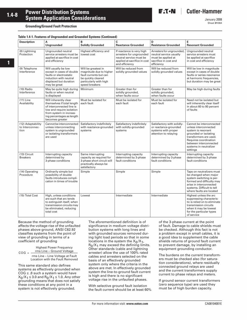
1.4-8
For more information visit: www.eaton.com CA08104001E
January 2008
Power Distribution Systems
i
ii
1
2
3
4
5
6
7
8
9
10
11
12
13
14
15
16
17
18
19
20
21
Sheet 01
System Application ConsiderationsGrounding/Ground Fault Protection
064
Table 1.4-1. Features of Ungrounded and Grounded Systems (Continued)
Because the method of grounding affects the voltage rise of the unfaulted phases above ground, ANSI C62.92 classifies systems from the point of view of grounding in terms of a coefficient of grounding
This same standard also defines systems as effectively grounded when COG ≤ .8 such a system would have X0/X1 ≤ 3.0 and R0/X1 ≤ 1.0. Any other grounding means that does not satisfy these conditions at any point in a system is not effectively grounded.
The aforementioned definition is of significance in medium voltage distri-bution systems with long lines and with grounded sources removed dur-ing light load periods so that in some locations in the system the X0/X1, R0/X1 may exceed the defining limits. Other standards (cable and lightning arrester) allow the use of 100% rated cables and arresters selected on the basis of an effectively grounded system only where the criteria in the above are met. In effectively grounded system the line-to-ground fault current is high and there is no significant voltage rise in the unfaulted phases.
With selective ground fault isolation the fault current should be at least 60%
of the 3-phase current at the point of fault. Damage to cable shields must be checked. Although this fact is not a problem except in small cables, it is a good idea to supplement the cable shields returns of ground fault current to prevent damage, by installing an equipment grounding conductor.
The burdens on the current transform-ers must be checked also (for satura-tion considerations), where residually connected ground relays are used and the current transformers supply current to phase relays and meters.
If ground sensor current transformers (zero sequence type) are used they must be of high burden capacity.
Description AUngrounded
BSolidly Grounded
CReactance Grounded
DResistance Grounded
EResonant Grounded
(8) Lightning Protection
Ungrounded neutral service arresters must be applied at sacrifice in cost and efficiency
Highest efficiency and lowest cost
If reactance is very high arresters for ungrounded neutral service must be applied at sacrifice in cost and efficiency
Arresters for ungrounded, neutral service usually must be applied at sacrifice in cost and efficiency
Ungrounded neutral service arresters must be applied at sacrifice in cost and efficiency
(9) TelephoneInterference
Will usually be low except in cases of double faults or electrostatic induction with neutral displaced but duration may be great
Will be greatest in magnitude due to higher fault currents but can be quickly cleared particularly with high speed breakers
Will be reduced from solidly grounded values
Will be reduced from solidly grounded values
Will be low in magnitude except in cases of double faults or series resonance at harmonic frequencies, but duration may be great
(10) Radio Interference
May be quite high during faults or when neutral is displayed
Minimum Greater than for solidly grounded, when faults occur
Greater than for solidly grounded, when faults occur
May be high during faults
(11) Line Availability
Will inherently clear themselves if total length of interconnected line is low and require isolation from system in increas-ing percentages as length becomes greater
Must be isolated for each fault
Must be isolated for each fault
Must be isolated for each fault
Need not be isolated but will inherently clear itself in about 60 to 80 percent of faults
(12) Adaptability to Interconnec-tion
Cannot be interconnected unless interconnecting system is ungrounded or isolating transformers are used
Satisfactory indefinitely with reactance-grounded systems
Satisfactory indefinitely with solidly-grounded systems
Satisfactory with solidly- or reactance-grounded systems with proper attention to relaying
Cannot be interconnected unless interconnected system is resonant grounded or isolating transformers are used. Requires coordination between interconnected systems in neutralizer settings
(13) Circuit Breakers
Interrupting capacity determined by 3-phase conditions
Same interrupting capacity as required for 3-phase short circuit will practically always be satisfactory
Interrupting capacity determined by 3-phase fault conditions
Interrupting capacity determined by 3-phase fault conditions
Interrupting capacity determined by 3-phase fault conditions
(14) Operating Procedure
Ordinarily simple but possibility of double faults introduces compli-cation in times of trouble
Simple Simple Simple Taps on neutralizers must be changed when major system switching is per-formed and difficulty may arise in interconnected systems. Difficult to tell where faults are located
(15) Total Cost High, unless conditions are such that arc tends to extinguish itself, when transmission circuits may be eliminated, reducing total cost
Lowest Intermediate Intermediate Highest unless the arc suppressing characteris-tic is relied on to eliminate transmission circuits when it may be lowest for the particular types of service
COG
Highest Power Frequencyrms Line – Ground Voltage
rms Line – Line Voltage at FaultLocation with the Fault Removed
---------------------------------------------------------------------------------------------=
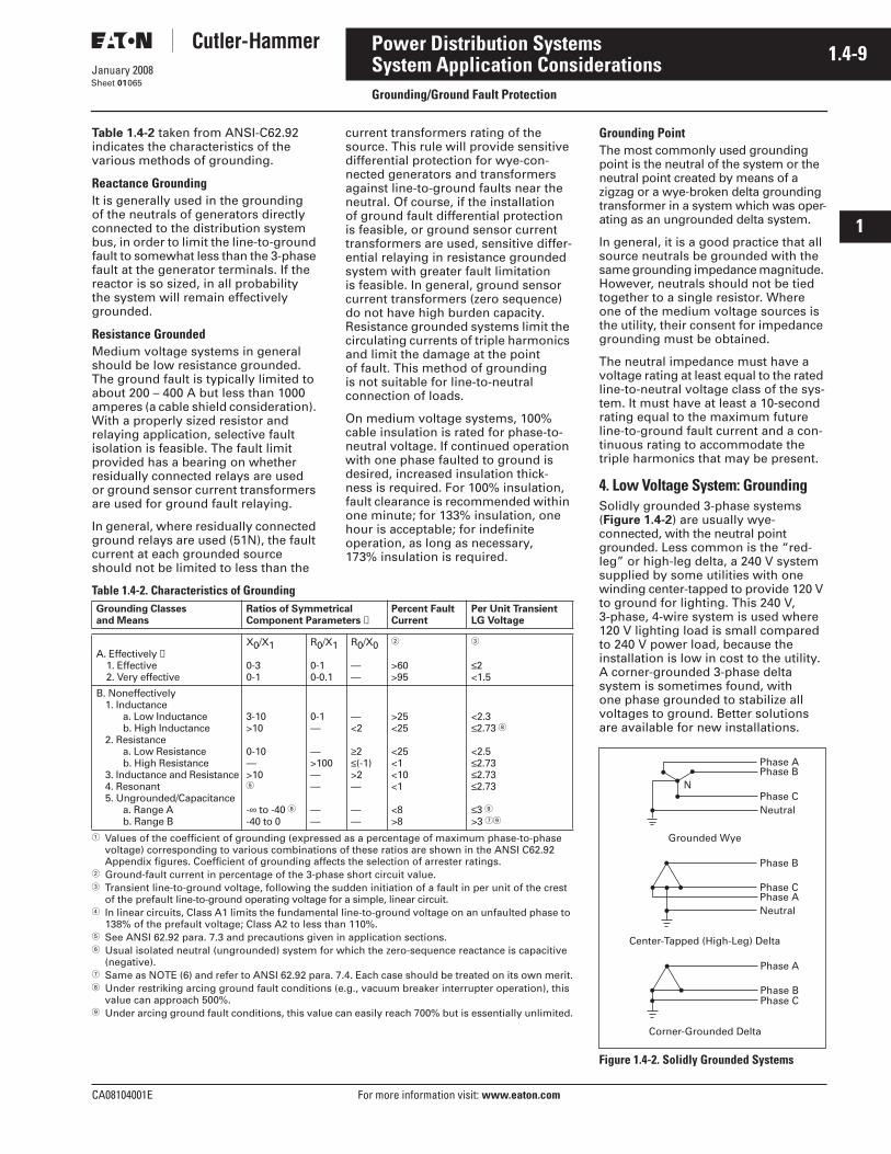
CA08104001E For more information visit: www.eaton.com
1.4-9January 2008
Power Distribution Systems
i
ii
1
2
3
4
5
6
7
8
9
10
11
12
13
14
15
16
17
18
19
20
21
Sheet 01
System Application ConsiderationsGrounding/Ground Fault Protection
065
Table 1.4-2 taken from ANSI-C62.92 indicates the characteristics of the various methods of grounding.
Reactance GroundingIt is generally used in the grounding of the neutrals of generators directly connected to the distribution system bus, in order to limit the line-to-ground fault to somewhat less than the 3-phase fault at the generator terminals. If the reactor is so sized, in all probability the system will remain effectively grounded.
Resistance GroundedMedium voltage systems in general should be low resistance grounded. The ground fault is typically limited to about 200 – 400 A but less than 1000 amperes (a cable shield consideration). With a properly sized resistor and relaying application, selective fault isolation is feasible. The fault limit provided has a bearing on whether residually connected relays are used or ground sensor current transformers are used for ground fault relaying.
In general, where residually connected ground relays are used (51N), the fault current at each grounded source should not be limited to less than the
current transformers rating of the source. This rule will provide sensitive differential protection for wye-con-nected generators and transformers against line-to-ground faults near the neutral. Of course, if the installation of ground fault differential protection is feasible, or ground sensor current transformers are used, sensitive differ-ential relaying in resistance grounded system with greater fault limitation is feasible. In general, ground sensor current transformers (zero sequence) do not have high burden capacity. Resistance grounded systems limit the circulating currents of triple harmonics and limit the damage at the point of fault. This method of grounding is not suitable for line-to-neutral connection of loads.
On medium voltage systems, 100% cable insulation is rated for phase-to-neutral voltage. If continued operation with one phase faulted to ground is desired, increased insulation thick-ness is required. For 100% insulation, fault clearance is recommended within one minute; for 133% insulation, one hour is acceptable; for indefinite operation, as long as necessary, 173% insulation is required.
Table 1.4-2. Characteristics of Grounding
� Values of the coefficient of grounding (expressed as a percentage of maximum phase-to-phase voltage) corresponding to various combinations of these ratios are shown in the ANSI C62.92 Appendix figures. Coefficient of grounding affects the selection of arrester ratings.
� Ground-fault current in percentage of the 3-phase short circuit value.� Transient line-to-ground voltage, following the sudden initiation of a fault in per unit of the crest
of the prefault line-to-ground operating voltage for a simple, linear circuit.� In linear circuits, Class A1 limits the fundamental line-to-ground voltage on an unfaulted phase to
138% of the prefault voltage; Class A2 to less than 110%.� See ANSI 62.92 para. 7.3 and precautions given in application sections.� Usual isolated neutral (ungrounded) system for which the zero-sequence reactance is capacitive
(negative).� Same as NOTE (6) and refer to ANSI 62.92 para. 7.4. Each case should be treated on its own merit.� Under restriking arcing ground fault conditions (e.g., vacuum breaker interrupter operation), this
value can approach 500%. Under arcing ground fault conditions, this value can easily reach 700% but is essentially unlimited.
Grounding Classesand Means
Ratios of SymmetricalComponent Parameters ➀
Percent FaultCurrent
Per Unit TransientLG Voltage
A. Effectively ➃1. Effective2. Very effective
X0/X1
0-30-1
R0/X1
0-10-0.1
R0/X0
——
�
>60>95
�
≤2<1.5
B. Noneffectively1. Inductance
a. Low Inductanceb. High Inductance
2. Resistancea. Low Resistanceb. High Resistance
3. Inductance and Resistance4. Resonant5. Ungrounded/Capacitance
a. Range Ab. Range B
3-10>10
0-10—>10�
-∞ to -40 �-40 to 0
0-1—
—>100——
——
—<2
≥2≤(-1)>2—
——
>25<25
<25<1<10<1
<8>8
<2.3≤2.73 �
<2.5≤2.73≤2.73≤2.73
≤3 >3 �
Grounding PointThe most commonly used grounding point is the neutral of the system or the neutral point created by means of a zigzag or a wye-broken delta grounding transformer in a system which was oper-ating as an ungrounded delta system.
In general, it is a good practice that all source neutrals be grounded with the same grounding impedance magnitude. However, neutrals should not be tied together to a single resistor. Where one of the medium voltage sources is the utility, their consent for impedance grounding must be obtained.
The neutral impedance must have a voltage rating at least equal to the rated line-to-neutral voltage class of the sys-tem. It must have at least a 10-second rating equal to the maximum future line-to-ground fault current and a con-tinuous rating to accommodate the triple harmonics that may be present.
4. Low Voltage System: GroundingSolidly grounded 3-phase systems (Figure 1.4-2) are usually wye-connected, with the neutral point grounded. Less common is the “red-leg” or high-leg delta, a 240 V system supplied by some utilities with one winding center-tapped to provide 120 V to ground for lighting. This 240 V, 3-phase, 4-wire system is used where 120 V lighting load is small compared to 240 V power load, because the installation is low in cost to the utility. A corner-grounded 3-phase delta system is sometimes found, with one phase grounded to stabilize all voltages to ground. Better solutions are available for new installations.
Figure 1.4-2. Solidly Grounded Systems
•• • •
•
Phase B
Phase CPhase ANeutral
Center-Tapped (High-Leg) Delta
Grounded Wye
•
•• •• Phase C
Phase APhase B
Neutral
N
• Phase A
Phase BPhase C•• •
Corner-Grounded Delta
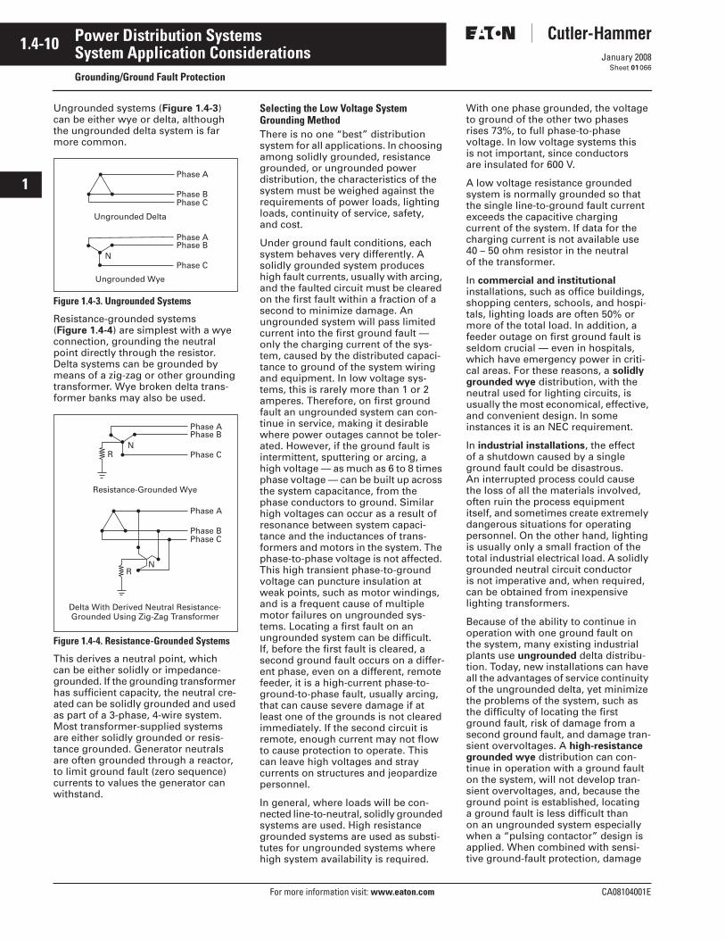
1.4-10
For more information visit: www.eaton.com CA08104001E
January 2008
Power Distribution Systems
i
ii
1
2
3
4
5
6
7
8
9
10
11
12
13
14
15
16
17
18
19
20
21
Sheet 01
System Application ConsiderationsGrounding/Ground Fault Protection
066
Ungrounded systems (Figure 1.4-3) can be either wye or delta, although the ungrounded delta system is far more common.
Figure 1.4-3. Ungrounded Systems
Resistance-grounded systems (Figure 1.4-4) are simplest with a wye connection, grounding the neutral point directly through the resistor. Delta systems can be grounded by means of a zig-zag or other grounding transformer. Wye broken delta trans-former banks may also be used.
Figure 1.4-4. Resistance-Grounded Systems
This derives a neutral point, which can be either solidly or impedance-grounded. If the grounding transformer has sufficient capacity, the neutral cre-ated can be solidly grounded and used as part of a 3-phase, 4-wire system. Most transformer-supplied systems are either solidly grounded or resis-tance grounded. Generator neutrals are often grounded through a reactor, to limit ground fault (zero sequence) currents to values the generator can withstand.
Selecting the Low Voltage System Grounding MethodThere is no one “best” distribution system for all applications. In choosing among solidly grounded, resistance grounded, or ungrounded power distribution, the characteristics of the system must be weighed against the requirements of power loads, lighting loads, continuity of service, safety, and cost.
Under ground fault conditions, each system behaves very differently. A solidly grounded system produces high fault currents, usually with arcing, and the faulted circuit must be cleared on the first fault within a fraction of a second to minimize damage. An ungrounded system will pass limited current into the first ground fault —only the charging current of the sys-tem, caused by the distributed capaci-tance to ground of the system wiring and equipment. In low voltage sys-tems, this is rarely more than 1 or 2 amperes. Therefore, on first ground fault an ungrounded system can con-tinue in service, making it desirable where power outages cannot be toler-ated. However, if the ground fault is intermittent, sputtering or arcing, a high voltage — as much as 6 to 8 times phase voltage — can be built up across the system capacitance, from the phase conductors to ground. Similar high voltages can occur as a result of resonance between system capaci-tance and the inductances of trans-formers and motors in the system. The phase-to-phase voltage is not affected. This high transient phase-to-ground voltage can puncture insulation at weak points, such as motor windings, and is a frequent cause of multiple motor failures on ungrounded sys-tems. Locating a first fault on an ungrounded system can be difficult. If, before the first fault is cleared, a second ground fault occurs on a differ-ent phase, even on a different, remote feeder, it is a high-current phase-to-ground-to-phase fault, usually arcing, that can cause severe damage if at least one of the grounds is not cleared immediately. If the second circuit is remote, enough current may not flow to cause protection to operate. This can leave high voltages and stray currents on structures and jeopardize personnel.
In general, where loads will be con-nected line-to-neutral, solidly grounded systems are used. High resistance grounded systems are used as substi-tutes for ungrounded systems where high system availability is required.
With one phase grounded, the voltage to ground of the other two phases rises 73%, to full phase-to-phase voltage. In low voltage systems this is not important, since conductors are insulated for 600 V.
A low voltage resistance grounded system is normally grounded so that the single line-to-ground fault current exceeds the capacitive charging current of the system. If data for the charging current is not available use 40 – 50 ohm resistor in the neutral of the transformer.
In commercial and institutional installations, such as office buildings, shopping centers, schools, and hospi-tals, lighting loads are often 50% or more of the total load. In addition, a feeder outage on first ground fault is seldom crucial — even in hospitals, which have emergency power in criti-cal areas. For these reasons, a solidly grounded wye distribution, with the neutral used for lighting circuits, is usually the most economical, effective, and convenient design. In some instances it is an NEC requirement.
In industrial installations, the effect of a shutdown caused by a single ground fault could be disastrous. An interrupted process could cause the loss of all the materials involved, often ruin the process equipment itself, and sometimes create extremely dangerous situations for operating personnel. On the other hand, lighting is usually only a small fraction of the total industrial electrical load. A solidly grounded neutral circuit conductor is not imperative and, when required, can be obtained from inexpensive lighting transformers.
Because of the ability to continue in operation with one ground fault on the system, many existing industrial plants use ungrounded delta distribu-tion. Today, new installations can have all the advantages of service continuity of the ungrounded delta, yet minimize the problems of the system, such as the difficulty of locating the first ground fault, risk of damage from a second ground fault, and damage tran-sient overvoltages. A high-resistance grounded wye distribution can con-tinue in operation with a ground fault on the system, will not develop tran-sient overvoltages, and, because the ground point is established, locating a ground fault is less difficult than on an ungrounded system especially when a “pulsing contactor” design is applied. When combined with sensi-tive ground-fault protection, damage
Phase B
• Phase A
Phase C• •
Ungrounded Delta
Ungrounded Wye
•• •• Phase C
Phase APhase B
N
•
Resistance-Grounded Wye
• •• Phase C
Phase APhase B
RN
• • Phase A
••
•
•Phase BPhase C
• •
Delta With Derived Neutral Resistance-Grounded Using Zig-Zag Transformer
•R
N
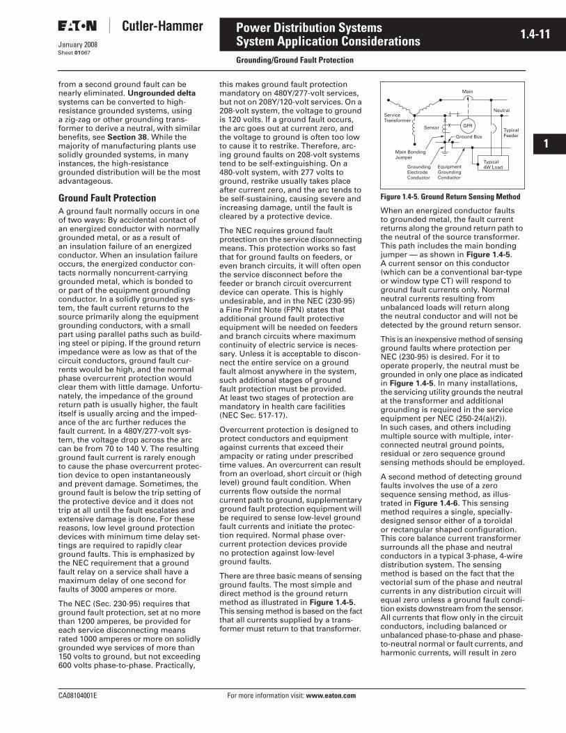
CA08104001E For more information visit: www.eaton.com
1.4-11January 2008
Power Distribution Systems
i
ii
1
2
3
4
5
6
7
8
9
10
11
12
13
14
15
16
17
18
19
20
21
Sheet 01
System Application ConsiderationsGrounding/Ground Fault Protection
067
from a second ground fault can be nearly eliminated. Ungrounded delta systems can be converted to high-resistance grounded systems, using a zig-zag or other grounding trans-former to derive a neutral, with similar benefits, see Section 38. While the majority of manufacturing plants use solidly grounded systems, in many instances, the high-resistance grounded distribution will be the most advantageous.
Ground Fault ProtectionA ground fault normally occurs in one of two ways: By accidental contact of an energized conductor with normally grounded metal, or as a result of an insulation failure of an energized conductor. When an insulation failure occurs, the energized conductor con-tacts normally noncurrent-carrying grounded metal, which is bonded to or part of the equipment grounding conductor. In a solidly grounded sys-tem, the fault current returns to the source primarily along the equipment grounding conductors, with a small part using parallel paths such as build-ing steel or piping. If the ground return impedance were as low as that of the circuit conductors, ground fault cur-rents would be high, and the normal phase overcurrent protection would clear them with little damage. Unfortu-nately, the impedance of the ground return path is usually higher, the fault itself is usually arcing and the imped-ance of the arc further reduces the fault current. In a 480Y/277-volt sys-tem, the voltage drop across the arc can be from 70 to 140 V. The resulting ground fault current is rarely enough to cause the phase overcurrent protec-tion device to open instantaneously and prevent damage. Sometimes, the ground fault is below the trip setting of the protective device and it does not trip at all until the fault escalates and extensive damage is done. For these reasons, low level ground protection devices with minimum time delay set-tings are required to rapidly clear ground faults. This is emphasized by the NEC requirement that a ground fault relay on a service shall have a maximum delay of one second for faults of 3000 amperes or more.
The NEC (Sec. 230-95) requires that ground fault protection, set at no more than 1200 amperes, be provided for each service disconnecting means rated 1000 amperes or more on solidly grounded wye services of more than 150 volts to ground, but not exceeding 600 volts phase-to-phase. Practically,
this makes ground fault protection mandatory on 480Y/277-volt services, but not on 208Y/120-volt services. On a 208-volt system, the voltage to ground is 120 volts. If a ground fault occurs, the arc goes out at current zero, and the voltage to ground is often too low to cause it to restrike. Therefore, arc-ing ground faults on 208-volt systems tend to be self-extinguishing. On a 480-volt system, with 277 volts to ground, restrike usually takes place after current zero, and the arc tends to be self-sustaining, causing severe and increasing damage, until the fault is cleared by a protective device.
The NEC requires ground fault protection on the service disconnecting means. This protection works so fast that for ground faults on feeders, or even branch circuits, it will often open the service disconnect before the feeder or branch circuit overcurrent device can operate. This is highly undesirable, and in the NEC (230-95) a Fine Print Note (FPN) states that additional ground fault protective equipment will be needed on feeders and branch circuits where maximum continuity of electric service is neces-sary. Unless it is acceptable to discon-nect the entire service on a ground fault almost anywhere in the system, such additional stages of ground fault protection must be provided. At least two stages of protection are mandatory in health care facilities (NEC Sec. 517-17).
Overcurrent protection is designed to protect conductors and equipment against currents that exceed their ampacity or rating under prescribed time values. An overcurrent can result from an overload, short circuit or (high level) ground fault condition. When currents flow outside the normal current path to ground, supplementary ground fault protection equipment will be required to sense low-level ground fault currents and initiate the protec-tion required. Normal phase over-current protection devices provide no protection against low-level ground faults.
There are three basic means of sensing ground faults. The most simple and direct method is the ground return method as illustrated in Figure 1.4-5. This sensing method is based on the fact that all currents supplied by a trans-former must return to that transformer.
Figure 1.4-5. Ground Return Sensing Method
When an energized conductor faults to grounded metal, the fault current returns along the ground return path to the neutral of the source transformer. This path includes the main bonding jumper — as shown in Figure 1.4-5. A current sensor on this conductor (which can be a conventional bar-type or window type CT) will respond to ground fault currents only. Normal neutral currents resulting from unbalanced loads will return along the neutral conductor and will not be detected by the ground return sensor.
This is an inexpensive method of sensing ground faults where protection per NEC (230-95) is desired. For it to operate properly, the neutral must be grounded in only one place as indicated in Figure 1.4-5. In many installations, the servicing utility grounds the neutral at the transformer and additional grounding is required in the service equipment per NEC (250-24(a)(2)). In such cases, and others including multiple source with multiple, inter-connected neutral ground points, residual or zero sequence ground sensing methods should be employed.
A second method of detecting ground faults involves the use of a zero sequence sensing method, as illus-trated in Figure 1.4-6. This sensing method requires a single, specially-designed sensor either of a toroidal or rectangular shaped configuration. This core balance current transformer surrounds all the phase and neutral conductors in a typical 3-phase, 4-wire distribution system. The sensing method is based on the fact that the vectorial sum of the phase and neutral currents in any distribution circuit will equal zero unless a ground fault condi-tion exists downstream from the sensor. All currents that flow only in the circuit conductors, including balanced or unbalanced phase-to-phase and phase-to-neutral normal or fault currents, and harmonic currents, will result in zero
Main
GFR
Neutral
TypicalFeeder
Sensor
Main BondingJumper
EquipmentGroundingConductor
GroundingElectrodeConductor
Typical4W Load
ServiceTransformer
Ground Bus
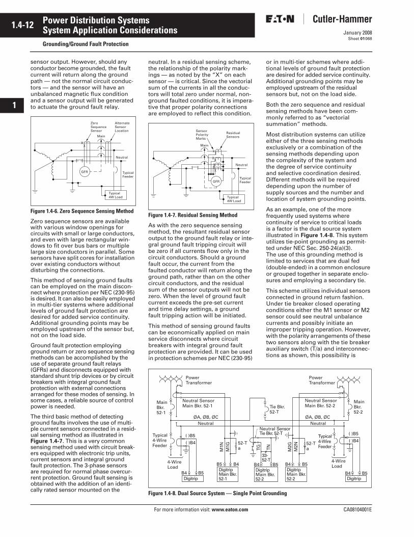
1.4-12
For more information visit: www.eaton.com CA08104001E
January 2008
Power Distribution Systems
i
ii
1
2
3
4
5
6
7
8
9
10
11
12
13
14
15
16
17
18
19
20
21
Sheet 01
System Application ConsiderationsGrounding/Ground Fault Protection
068
sensor output. However, should any conductor become grounded, the fault current will return along the ground path — not the normal circuit conduc-tors — and the sensor will have an unbalanced magnetic flux condition and a sensor output will be generated to actuate the ground fault relay.
Figure 1.4-6. Zero Sequence Sensing Method
Zero sequence sensors are available with various window openings for circuits with small or large conductors, and even with large rectangular win-dows to fit over bus bars or multiple large size conductors in parallel. Some sensors have split cores for installation over existing conductors without disturbing the connections.
This method of sensing ground faults can be employed on the main discon-nect where protection per NEC (230-95) is desired. It can also be easily employed in multi-tier systems where additional levels of ground fault protection are desired for added service continuity. Additional grounding points may be employed upstream of the sensor but, not on the load side.
Ground fault protection employing ground return or zero sequence sensing methods can be accomplished by the use of separate ground fault relays (GFRs) and disconnects equipped with standard shunt trip devices or by circuit breakers with integral ground fault protection with external connections arranged for these modes of sensing. In some cases, a reliable source of control power is needed.
The third basic method of detecting ground faults involves the use of multi-ple current sensors connected in a resid-ual sensing method as illustrated in Figure 1.4-7. This is a very common sensing method used with circuit break-ers equipped with electronic trip units, current sensors and integral ground fault protection. The 3-phase sensors are required for normal phase overcur-rent protection. Ground fault sensing is obtained with the addition of an identi-cally rated sensor mounted on the
ZeroSequenceSensor
Main
Neutral
TypicalFeeder
AlternateSensorLocation
Typical4W Load
GFR
neutral. In a residual sensing scheme, the relationship of the polarity mark-ings — as noted by the “X” on each sensor — is critical. Since the vectorial sum of the currents in all the conduc-tors will total zero under normal, non-ground faulted conditions, it is impera-tive that proper polarity connections are employed to reflect this condition.
Figure 1.4-7. Residual Sensing Method
As with the zero sequence sensing method, the resultant residual sensor output to the ground fault relay or inte-gral ground fault tripping circuit will be zero if all currents flow only in the circuit conductors. Should a ground fault occur, the current from the faulted conductor will return along the ground path, rather than on the other circuit conductors, and the residual sum of the sensor outputs will not be zero. When the level of ground fault current exceeds the pre-set current and time delay settings, a ground fault tripping action will be initiated.
This method of sensing ground faults can be economically applied on main service disconnects where circuit breakers with integral ground fault protection are provided. It can be used in protection schemes per NEC (230-95)
or in multi-tier schemes where addi-tional levels of ground fault protection are desired for added service continuity. Additional grounding points may be employed upstream of the residual sensors but, not on the load side.
Both the zero sequence and residual sensing methods have been com-monly referred to as “vectorial summation” methods.
Most distribution systems can utilize either of the three sensing methods exclusively or a combination of the sensing methods depending upon the complexity of the system and the degree of service continuity and selective coordination desired. Different methods will be required depending upon the number of supply sources and the number and location of system grounding points.
As an example, one of the more frequently used systems where continuity of service to critical loads is a factor is the dual source system illustrated in Figure 1.4-8. This system utilizes tie-point grounding as permit-ted under NEC Sec. 250-24(a)(3). The use of this grounding method is limited to services that are dual fed (double-ended) in a common enclosure or grouped together in separate enclo-sures and employing a secondary tie.
This scheme utilizes individual sensors connected in ground return fashion. Under tie breaker closed operating conditions either the M1 sensor or M2 sensor could see neutral unbalance currents and possibly initiate an improper tripping operation. However, with the polarity arrangements of these two sensors along with the tie breaker auxiliary switch (T/a) and interconnec-tions as shown, this possibility is
Figure 1.4-8. Dual Source System — Single Point Grounding
GFR
Typical4W Load
SensorPolarityMarks
Neutral
TypicalFeeder
Main
ResidualSensors
Typical4-WireFeeder
4-WireLoad
Neutral ØA, ØB, ØC
Power Transformer
Power Transformer
4-Wire Load
Typical 4-WireFeeder
Neutral ØA, ØB, ØC
33-52-T
52-T a
52-Ta
Tie Bkr. 52-T
Neutral Sensor Main Bkr. 52-2
Neutral SensorTie Bkr. 52-T
Neutral SensorMain Bkr. 52-1
DigitripMain Bkr. 52-1
MainBkr.52-2
Main Bkr.52-1
Digitrip
DigitripMain Bkr. 52-2 Digitrip
B4 B5
B5 B4 B4 B5 B4 B5
B4 B5
( )B4
( )B5
M1N
M1G
M2G
M2N
TG TN
( )B4
( )B5
DigitripMain Bkr. 52-2
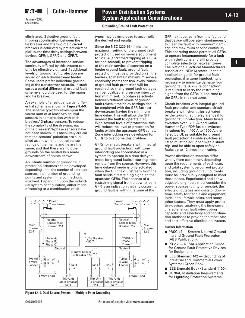
CA08104001E For more information visit: www.eaton.com
1.4-13January 2008
Power Distribution Systems
i
ii
1
2
3
4
5
6
7
8
9
10
11
12
13
14
15
16
17
18
19
20
21
Sheet 01
System Application ConsiderationsGrounding/Ground Fault Protection
069
eliminated. Selective ground fault tripping coordination between thetie breaker and the two main circuit breakers is achieved by pre-set current pickup and time delay settings between devices GFR/1, GFR/2 and GFR/T.
The advantages of increased service continuity offered by this system can only be effectively utilized if additional levels of ground fault protection are added on each downstream feeder. Some users prefer individual ground-ing of the transformer neutrals. In such cases a partial differential ground fault scheme should be used for the mains and tie breaker.
An example of a residual partial differ-ential scheme is shown in Figure 1.4-9. The scheme typically relies upon the vector sum of at least two neutral sensors in combination with each breakers’ 3-phase sensors. To reduce the complexity of the drawing, each of the breakers’ 3-phase sensors have not been shown. It is absolutely critical that the sensors’ polarities are sup-plied as shown, the neutral sensor ratings of the mains and tie are the same, and that there are no other grounds on the neutral bus made downstream of points shown.
An infinite number of ground fault protection schemes can be developed depending upon the number of alternate sources, the number of grounding points and system interconnections involved. Depending upon the individ-ual system configuration, either mode of sensing or a combination of all
types may be employed to accomplish the desired end results.
Since the NEC (230-95) limits the maximum setting of the ground fault protection used on service equipment to 1200 A (and timed tripping at 3000 A for one second), to prevent tripping of the main service disconnect on a feeder ground fault, ground fault protection must be provided on all the feeders. To maintain maximum service continuity, more than two levels (zones) of ground fault protection will be required, so that ground fault outages can be localized and service interrup-tion minimized. To obtain selectivity between different levels of ground fault relays, time delay settings should be employed with the GFR furthest downstream having the minimum time delay. This will allow the GFR nearest the fault to operate first. With several levels of protection, this will reduce the level of protection for faults within the upstream GFR zones. Zone interlocking was developed for GFRs to overcome this problem.
GFRs (or circuit breakers with integral ground fault protection) with zone interlocking are coordinated in a system to operate in a time delayed mode for ground faults occurring most remote from the source. However, this time delayed mode is only actuated when the GFR next upstream from the fault sends a restraining signal to the upstream GFRs. The absence of a restraining signal from a downstream GFR is an indication that any occurring ground fault is within the zone of the
Figure 1.4-9. Dual Source System — Multiple Point Grounding
Trip UnitMain Breaker
52-1
Trip UnitTie Breaker
52-T
PowerTransformer
52-Ta
52-2a
Neutral SensorTie Breaker 52-T
XX
Typical4-Wire Feeder Tr
ip U
nit
4-Wire Load
XX
52-1a
Neutral Neutral
Tie Breaker52-T
NeutralSensor MainBreaker 52-1
XX
XX
MainBreaker52-1
Phase A,Phase B,Phase C
Trip UnitMain Breaker
52-2
Typical4-Wire Feeder Tr
ip U
nit
4-Wire Load
XX
Phase A,Phase B,Phase C
PowerTransformer
NeutralSensor MainBreaker 52-2 Main
Breaker52-2
GFR next upstream from the fault and that device will operate instantaneously to clear the fault with minimum dam-age and maximum service continuity. This operating mode permits all GFRs to operate instantaneously for a fault within their zone and still provide complete selectivity between zones. The National Electrical Manufacturers Association (NEMA) states, in their application guide for ground fault protection, that zone interlocking is necessary to minimize damage from ground faults. A 2-wire connection is required to carry the restraining signal from the GFRs in one zone to the GFRs in the next zone.
Circuit breakers with integral ground fault protection and standard circuit breakers with shunt trips activated by the ground fault relay are ideal for ground fault protection. Many fused switches over 1200 A, and Cutler-Hammer Type FDP fusible switches in ratings from 400 A to 1200 A, are listed by UL as suitable for ground fault protection. Fusible switches so listed must be equipped with a shunt trip, and be able to open safely on faults up to 12 times their rating.
Power distribution systems differ widely from each other, depending upon the requirements of each user, and total system overcurrent protec-tion, including ground fault currents, must be individually designed to meet these needs. Experienced and knowl-edgeable engineers must consider the power sources (utility or on-site), the effects of outages and costs of down-time, safety for people and equipment, initial and lifecycle costs, and many other factors. They must apply protec-tive devices, analyzing the time-current characteristics, fault interrupting capacity, and selectivity and coordina-tion methods to provide the most safe and cost-effective distribution system.
Further Information■ PRSC-4E — System Neutral Ground-
ing and Ground Fault Protection (ABB Publication).
■ PB 2.2 — NEMA Application Guide for Ground Fault Protective Devices for Equipment.
■ IEEE Standard 142 — Grounding of Industrial and Commercial Power Systems (Green Book).
■ IEEE Emerald Book (Standard 1100).■ UL 96A, Installation Requirements
for Lightning Protection Systems.
1.4-14
For more information visit: www.eaton.com CA08104001E
January 2008
Power Distribution Systems
i
ii
1
2
3
4
5
6
7
8
9
10
11
12
13
14
15
16
17
18
19
20
21
Sheet 01
System Application ConsiderationsGrounding/Ground Fault Protection
070
Lightning and Surge ProtectionPhysical protection of buildings from direct damage from lightning is beyond the scope of this section. Requirements will vary with geo-graphic location, building type and environment, and many other factors (see IEEE/ANSI Standard 142, Ground-ing of Industrial and Commercial Power Systems). Any lightning protec-tion system must be grounded, and the lightning protection ground must be bonded to the electrical equipment grounding system.
Grounding ElectrodesAt some point, the equipment and system grounds must be connected to the earth by means of a grounding electrode system.
Outdoor substations usually use a ground grid, consisting of a number of ground rods driven into the earth and bonded together by buried copper conductors. The required grounding electrode system for a building is spelled out in the NEC Article 250.
The preferred grounding electrode is a metal underground water pipe in direct contact with the earth for at least 10 feet (3 m). However, because under-ground water piping is often plastic outside the building, or may later be replaced by plastic piping, the NEC requires this electrode to be supple-mented by and bonded to at least one other grounding electrode, such as the effectively grounded metal frame of the building, a concrete-encased electrode, a copper conductor ground ring encircling the building, or a made electrode such as one or more driven ground rods or a buried plate. Where any of these electrodes are present, they must be bonded together into one grounding electrode system.
One of the most effective grounding electrodes is the concrete-encased electrode, sometimes called the Ufer ground, named after the man who developed it. It consists of at least 20 feet (6 m) of steel reinforcing bars or rods not less than 1/2 inches (12.7 mm) in diameter, or at least 20 feet (6 m) of bare copper conductor, size No. 4 AWG or larger, encased in at least 2 inches (50.8 mm) of concrete. It must be located within and near the bottom of a concrete foundation or footing that is in direct contact with the earth. Tests have shown this electrode to provide a low-resistance earth ground even in poor soil conditions.
The electrical distribution system and equipment ground must be connected to this grounding electrode system by a grounding electrode conductor. All other grounding electrodes, such as those for the lightning protection sys-tem, the telephone system, television antenna and cable TV system grounds, and computer systems, must be bonded to this grounding electrode system.
Medium Voltage Equipment Surge Protection Considerations
TransformersIf the voltage withstand/BIL rating of the transformer is less than that of the switchgear feeding the transformer, surge protection is recommended at the transformer terminals, in line with established practices. In addition, con-sideration should be given to utilizing surge arresters and/or surge capaci-tors for transformers having equal or greater withstand/BIL ratings than that of the switchgear feeding the trans-former for distribution systems where reflected voltage waves and/or reso-nant conditions may occur. Typically incoming voltage surges are reflected at the transformer primary terminals (because of the change in impedance) resulting in voltages at the ends of the transformer primary terminals/wind-ings of up to two (2) times the incom-ing voltage wave. System capacitance and inductance values combined with the transformer impedance values can cause resonant conditions resulting in amplified reflected waves. Surge arresters/capacitors when required, should be located as close to the trans-former primary terminals as practical.
MotorsSurge capacitors and, where appropri-ate, surge arresters should be applied at the motor terminals.
GeneratorsSurge capacitors and station class surge arresters at the machine terminals.
Further Information■ IEEE/ANSI Standard 142 — Ground-
ing Industrial and Commercial Power Systems (Green Book).
■ IEEE Standard 241 — Electric Power Systems in Commercial Buildings (Gray Book).
■ IEEE Standard 141 — Electric Power Distribution for Industrial Plants (Red Book).
CA08104001E For more information visit: www.eaton.com
1.4-15January 2008
Power Distribution Systems
i
ii
1
2
3
4
5
6
7
8
9
10
11
12
13
14
15
16
17
18
19
20
21
Sheet 01
System Application ConsiderationsPower Quality
071
Power Quality TermsTechnical Overview
IntroductionSensitive electronic loads deployed today by users require strict require-ments for the quality of power delivered to loads.
For electronic equipment, power disturbances are defined in terms of amplitude and duration by the elec-tronic equipment operating envelope. Electronic loads may be damaged and disrupted, with shortened life expectancy, by disturbances.
The proliferation of computers, variable frequency motor drives, UPS systems and other electronically controlled equipment is placing a greater demand on power producers for a disturbance-free source of power. Not only do these types of equipment require quality power for proper operation; many times, these types of equipment are also the sources of power disturbances that corrupt the quality of power in a given facility.
Power Quality is defined according to IEEE Standard 1100 as the concept of powering and grounding electronic equipment in a manner that is suitable to the operation of that equipment. IEEE Standard 1159 notes that “within the industry, alternate definitions or interpretations of power quality have been used, reflecting different points of view.”
In addressing power quality problems at an existing site, or in the design stages of a new building, engineers need to specify different services or mitigating technologies. The lowest cost and highest value solution is to selectively apply a combination of dif-ferent products and services as follows:
Key Services/Technologies in the “Power Quality” Industry:
■ Power quality surveys, analysis and studies.
■ Power monitoring.■ Grounding products and services.■ Surge protection.■ Voltage regulation.■ Harmonic solutions.■ Lightning protection (ground rods,
hardware, etc.).■ Uninterruptible Power Supply (UPS)
or Motor-Generator (M-G) set.
Defining the ProblemPower quality problems can be resolved in three ways: by reducing the variations in the power supply (power distur-bances), by improving the load equip-ment’s tolerance to those variations, or by inserting some interface equipment (known as power conditioning equip-ment) between the electrical supply and the sensitive load(s) to improve the compatibility of the two. Practicality and cost usually determine the extent to which each option is used.
Many methods are used to define power quality problems. For example, one option is a thorough on-site investigation which includes inspecting wiring and grounding for errors, monitoring the power supply for power disturbances, investigating equipment sensitivity to power distur-bances, and determining the load disruption and consequential effects (costs), if any. In this way, the power quality problem can be defined, alternative solutions developed, and optimal solution chosen.
Before applying power-conditioning equipment to solve power quality problems, the site should be checked for wiring and grounding problems. Sometimes, correcting a relatively inexpensive wiring error, such as a loose connection or a reversed neutral and ground wire, can avoid a more expensive power conditioning solution.
Sometimes this approach is not practical because of limitations in time; expense is not justified for smaller installations; monitoring for power disturbances may be needed over an extended period of time to capture infrequent disturbances; the exact sensitivities of the load equipment may be unknown and difficult to determine; and finally, the investigative approach tends to solve only observed problems. Thus unobserved or potential problems may not be considered in the solution. For instance, when planning a new facility, there is no site to investigate. Therefore, power quality solutions are often implemented to solve potential or perceived problems on a preventive basis instead of a thorough on-site investigation.
Another option is to buy power condi-tioning equipment to correct any and all perceived power quality problems without any on-site investigation.
Power Quality TermsPower Disturbance: Any deviation from the nominal value (or from some selected thresholds based on load tolerance) of the input ac power characteristics.
Total Harmonic Distortion or Distortion Factor: The ratio of the root-mean-square of the harmonic content to the root-mean-square of the fundamental quantity, expressed as a percentage of the fundamental.
Crest Factor: Ratio between the peak value (crest) and rms value of a periodic waveform.
Apparent (Total) Power Factor: The ratio of the total power input in watts to the total volt-ampere input.
Sag: An rms reduction in the ac voltage, at the power frequency, for the duration from a half-cycle to a few seconds. An undervoltage would have a duration greater than several seconds.
Interruption: The complete loss of voltage for a time period.
Transient: A sub-cycle disturbance in the ac waveform that is evidenced by a sharp brief discontinuity of the waveform. May be of either polarity and may be additive to or subtractive from the nominal waveform.
Surge or Impulse: See transient.
Noise: Unwanted electrical signals that produce undesirable effects in the circuits of control systems in which they occur.
Common-Mode Noise: The noise volt-age that appears equally and in phase from each current-carrying conductor to ground.
Normal-Mode Noise: Noise signals measurable between or among active circuit conductors feeding the subject load, but not between the equipment grounding conductor or associated signal reference structure and the active circuit conductors.
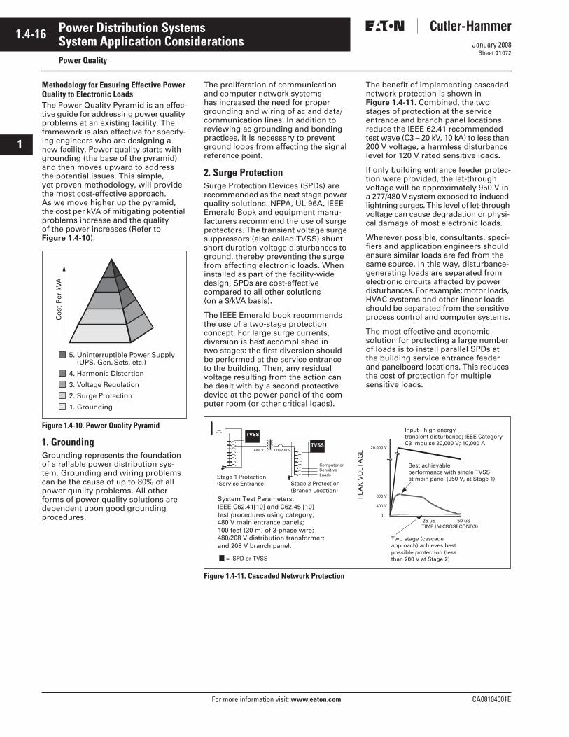
1.4-16
For more information visit: www.eaton.com CA08104001E
January 2008
Power Distribution Systems
i
ii
1
2
3
4
5
6
7
8
9
10
11
12
13
14
15
16
17
18
19
20
21
Sheet 01
System Application ConsiderationsPower Quality
072
Methodology for Ensuring Effective Power Quality to Electronic LoadsThe Power Quality Pyramid is an effec-tive guide for addressing power quality problems at an existing facility. The framework is also effective for specify-ing engineers who are designing a new facility. Power quality starts with grounding (the base of the pyramid) and then moves upward to address the potential issues. This simple, yet proven methodology, will provide the most cost-effective approach. As we move higher up the pyramid, the cost per kVA of mitigating potential problems increase and the quality of the power increases (Refer to Figure 1.4-10).
Figure 1.4-10. Power Quality Pyramid
1. GroundingGrounding represents the foundation of a reliable power distribution sys-tem. Grounding and wiring problems can be the cause of up to 80% of all power quality problems. All other forms of power quality solutions are dependent upon good grounding procedures.
5. Uninterruptible Power Supply(UPS, Gen. Sets, etc.)
4. Harmonic Distortion
3. Voltage Regulation
2. Surge Protection
1. Grounding
Co
st P
er k
VA
The proliferation of communication and computer network systems has increased the need for proper grounding and wiring of ac and data/communication lines. In addition to reviewing ac grounding and bonding practices, it is necessary to prevent ground loops from affecting the signal reference point.
2. Surge ProtectionSurge Protection Devices (SPDs) are recommended as the next stage power quality solutions. NFPA, UL 96A, IEEE Emerald Book and equipment manu-facturers recommend the use of surge protectors. The transient voltage surge suppressors (also called TVSS) shunt short duration voltage disturbances to ground, thereby preventing the surge from affecting electronic loads. When installed as part of the facility-wide design, SPDs are cost-effective compared to all other solutions (on a $/kVA basis).
The IEEE Emerald book recommends the use of a two-stage protection concept. For large surge currents, diversion is best accomplished in two stages: the first diversion should be performed at the service entrance to the building. Then, any residual voltage resulting from the action can be dealt with by a second protective device at the power panel of the com-puter room (or other critical loads).
The benefit of implementing cascaded network protection is shown in Figure 1.4-11. Combined, the two stages of protection at the service entrance and branch panel locations reduce the IEEE 62.41 recommended test wave (C3 – 20 kV, 10 kA) to less than 200 V voltage, a harmless disturbance level for 120 V rated sensitive loads.
If only building entrance feeder protec-tion were provided, the let-through voltage will be approximately 950 V in a 277/480 V system exposed to induced lightning surges. This level of let-through voltage can cause degradation or physi-cal damage of most electronic loads.
Wherever possible, consultants, speci-fiers and application engineers should ensure similar loads are fed from the same source. In this way, disturbance-generating loads are separated from electronic circuits affected by power disturbances. For example; motor loads, HVAC systems and other linear loads should be separated from the sensitive process control and computer systems.
The most effective and economic solution for protecting a large number of loads is to install parallel SPDs at the building service entrance feeder and panelboard locations. This reduces the cost of protection for multiplesensitive loads.
Figure 1.4-11. Cascaded Network Protection
Input - high energytransient disturbance; IEEE CategoryC3 Impulse 20,000 V; 10,000 A
Two stage (cascadeapproach) achieves bestpossible protection (lessthan 200 V at Stage 2)
Best achievableperformance with single TVSSat main panel (950 V, at Stage 1)
25 uS 50 uS TIME (MICROSECONDS)
20,000 V
800 V
400 V
0
CP
TVSS
TVSS
480 V 120/208 V
Stage 1 Protection(Service Entrance) Stage 2 Protection
(Branch Location)
Computer orSensitiveLoads
System Test Parameters:IEEE C62.41[10] and C62.45 [10]test procedures using category;480 V main entrance panels;100 feet (30 m) of 3-phase wire;480/208 V distribution transformer; and 208 V branch panel.
= SPD or TVSS
PE
AK
VO
LTA
GE
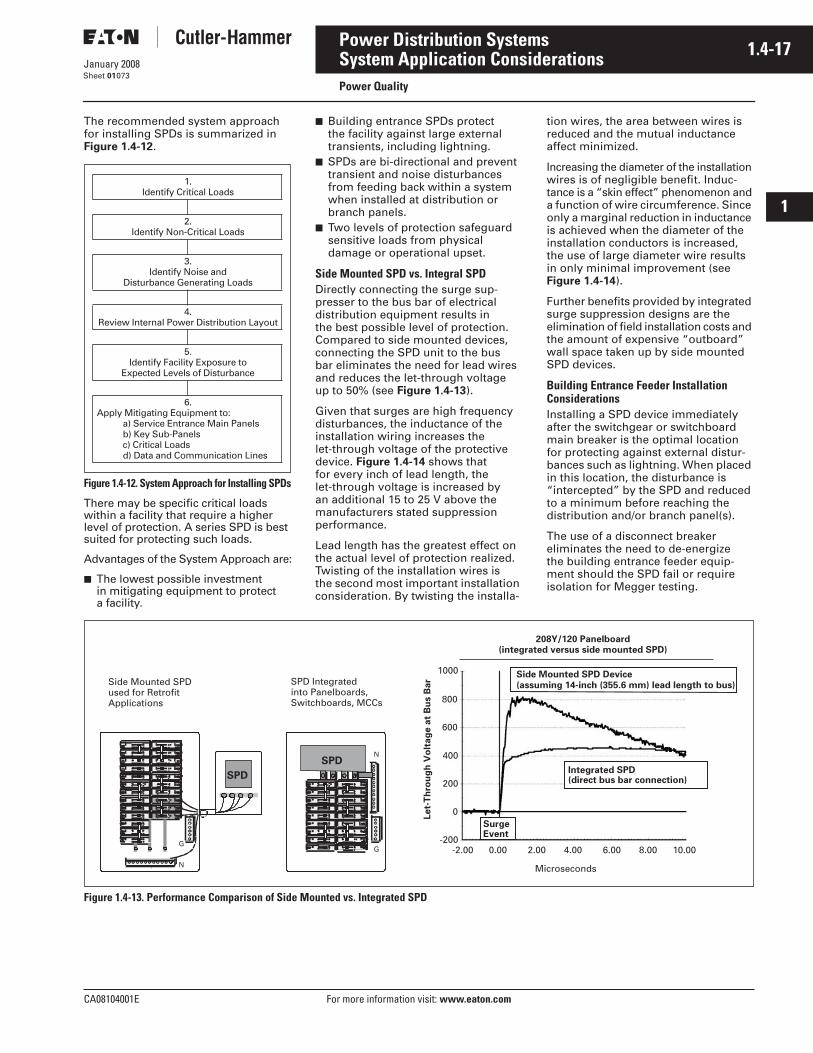
CA08104001E For more information visit: www.eaton.com
1.4-17January 2008
Power Distribution Systems
i
ii
1
2
3
4
5
6
7
8
9
10
11
12
13
14
15
16
17
18
19
20
21
Sheet 01
System Application ConsiderationsPower Quality
073
The recommended system approach for installing SPDs is summarized in Figure 1.4-12.
Figure 1.4-12. System Approach for Installing SPDs
There may be specific critical loads within a facility that require a higher level of protection. A series SPD is best suited for protecting such loads.
Advantages of the System Approach are:
■ The lowest possible investment in mitigating equipment to protect a facility.
■ Building entrance SPDs protect the facility against large external transients, including lightning.
■ SPDs are bi-directional and prevent transient and noise disturbances from feeding back within a system when installed at distribution or branch panels.
■ Two levels of protection safeguard sensitive loads from physical damage or operational upset.
Side Mounted SPD vs. Integral SPDDirectly connecting the surge sup-presser to the bus bar of electrical distribution equipment results in the best possible level of protection. Compared to side mounted devices, connecting the SPD unit to the bus bar eliminates the need for lead wires and reduces the let-through voltage up to 50% (see Figure 1.4-13).
Given that surges are high frequency disturbances, the inductance of the installation wiring increases the let-through voltage of the protective device. Figure 1.4-14 shows that for every inch of lead length, the let-through voltage is increased by an additional 15 to 25 V above the manufacturers stated suppression performance.
Lead length has the greatest effect on the actual level of protection realized. Twisting of the installation wires is the second most important installation consideration. By twisting the installa-
tion wires, the area between wires is reduced and the mutual inductance affect minimized.
Increasing the diameter of the installation wires is of negligible benefit. Induc-tance is a “skin effect” phenomenon and a function of wire circumference. Since only a marginal reduction in inductance is achieved when the diameter of the installation conductors is increased, the use of large diameter wire results in only minimal improvement (see Figure 1.4-14).
Further benefits provided by integrated surge suppression designs are the elimination of field installation costs and the amount of expensive “outboard” wall space taken up by side mounted SPD devices.
Building Entrance Feeder Installation ConsiderationsInstalling a SPD device immediately after the switchgear or switchboard main breaker is the optimal location for protecting against external distur-bances such as lightning. When placed in this location, the disturbance is “intercepted” by the SPD and reduced to a minimum before reaching the distribution and/or branch panel(s).
The use of a disconnect breaker eliminates the need to de-energize the building entrance feeder equip-ment should the SPD fail or require isolation for Megger testing.
Figure 1.4-13. Performance Comparison of Side Mounted vs. Integrated SPD
1.Identify Critical Loads
2.Identify Non-Critical Loads
3.Identify Noise and
Disturbance Generating Loads
4.Review Internal Power Distribution Layout
5.Identify Facility Exposure to
Expected Levels of Disturbance
6.Apply Mitigating Equipment to:
a) Service Entrance Main Panelsb) Key Sub-Panelsc) Critical Loadsd) Data and Communication Lines
\
G R O U N D
G
N
G R O U N D
G
NSPD
208Y/120 Panelboard(integrated versus side mounted SPD)
Side Mounted SPD Device
(assuming 14-inch (355.6 mm) lead length to bus)
Integrated SPD(direct bus bar connection)
SurgeEvent
Microseconds
SPD
Side Mounted SPDused for RetrofitApplications
SPD Integrated into Panelboards,Switchboards, MCCs
1000
800
600
400
200
0
-200-2.00 0.00 2.00 4.00 6.00 8.00 10.00
Let-
Th
rou
gh
Vo
ltag
e a
t B
us B
ar
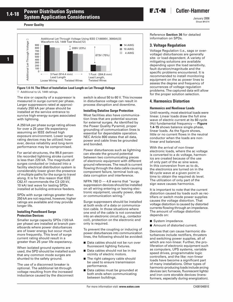
1.4-18
For more information visit: www.eaton.com CA08104001E
January 2008
Power Distribution Systems
i
ii
1
2
3
4
5
6
7
8
9
10
11
12
13
14
15
16
17
18
19
20
21
Sheet 01
System Application ConsiderationsPower Quality
074
Figure 1.4-14. The Effect of Installation Lead Length on Let-Through Voltage� Additional to UL 1449 ratings.
The size or capacity of a suppressor is measured in surge current per phase. Larger suppressors rated at approxi-mately 250 kA per phase should be installed at the service entrance to survive high-energy surges associated with lightning.
A 250 kA per phase surge rating allows for over a 25 year life expectancy assuming an IEEE defined high exposure environment. Lower surge rating devices may be utilized; how-ever, device reliability and long-term performance may be compromised.
For aerial structures, the 99.8 percen-tile recorded lightning stroke current is less than 220 kA. The magnitude of surges conducted or induced into a facility electrical distribution system is considerably lower given the presence of multiple paths for the surge to travel along. It is for this reason that IEEE C62.41 recommends the C3 (20 kV, 10 kA) test wave for testing SPDs installed at building entrance feeders.
SPDs with surge ratings greater than 250 kA are not required, however, higher ratings are available and may provide longer life.
Installing Panelboard Surge Protection DevicesSmaller surge capacity SPDs (120 kA per phase) are installed at branch pan-elboards where power disturbances are of lower energy but occur much more frequently. This level of surge current rating should result in a greater than 25 year life expectancy.
When isolated ground systems are used, the SPD should be installed such that any common mode surges are shunted to the safety ground.
The use of a disconnect breaker is optional. The additional let-through voltage resulting from the increased inductance caused by the disconnect
switch is about 50 to 60 V. This increase in disturbance voltage can result in process disruption and downtime.
Installing Dataline Surge ProtectionMost facilities also have communica-tion lines that are potential sources for external surges. As identified by the Power Quality Pyramid, proper grounding of communication lines is essential for dependable operation. NEC Article 800 states that all data, power and cable lines be grounded and bonded.
Power disturbances such as lightning can elevate the ground potential between two communicating pieces of electronic equipment with different ground references. The result is current flowing through the data cable causing component failure, terminal lock-up, data corruption and interference.
NFPA 780 D — 4.8 warns that “surge suppression devices should be installed on all wiring entering or leaving elec-tronic equipment, usually power, data or communication wiring.”
Surge suppressers should be installed at both ends of a data or communica-tion cable. In those situations where one end of the cable is not connected into an electronic circuit (e.g., contactor coil), protection on the electronic end only is required.
To prevent the coupling or inducing of power disturbances into communication lines, the following should be avoided:
■ Data cables should not be run over fluorescent lighting fixtures.
■ Data cables should not be in the vicinity of electric motors.
■ The right category cable should be used to ensure transmission performance.
■ Data cables must be grounded at both ends when communicating between buildings.
14 AWG 10 AWG
4 AWG
0100200300400500600700800900
209V (23%)
673V (75%)
Ad
dit
ion
al L
et-T
hro
ug
h V
olt
age
➀
Loose Wiring Twisted Wires
3 Feet (914.4 mm) Lead Length
1 Foot (304.8 mm) Lead Length, Twisted Wires
Additional Let-Through Voltage Using IEEE C1(6000V, 3000A)[3]Waveform (UL 1449 Test Wave)[12]
Reference Section 36 for detailed information on SPDs.
3. Voltage RegulationVoltage Regulation (i.e., sags or over-voltage) disturbances are generally site- or load-dependent. A variety of mitigating solutions are available depending upon the load sensitivity, fault duration/magnitude and the specific problems encountered. It is recommended to install monitoring equipment on the ac power lines to assess the degree and frequency of occurrences of voltage regulation problems. The captured data will allow for the proper solution selection.
4. Harmonics Distortion
Harmonics and Nonlinear LoadsUntil recently, most electrical loads were linear. Linear loads draw the full sine wave of electric current at its 60 cycle (Hz) fundamental frequency — Figure 1.4-15 shows balance single-phase, linear loads. As the figure shows, little or no current flows in the neutral conductor when the loads are non-linear and balanced.
With the arrival of non-linear electronic loads, where the ac voltage is converted to a dc voltage, harmon-ics are created because of the use of only part of the ac sine wave. In this conversion from ac to dc, the electronics are turned on in the 60 cycle wave at a given point in time to obtain the required dc level. The utilization of only part of the sign wave causes harmonics.
It is important to note that the current distortion caused by loads such as rec-tifiers or switch mode power supplies causes the voltage distortion. That voltage distortion is caused by distorted currents flowing through an impedance. The amount of voltage distortion depends on:
■ System impedance.■ Amount of distorted current.
Devices that can cause harmonic dis-turbances include rectifiers, thrusters and switching power supplies, all of which are non-linear. Further, the pro-liferation of electronic equipment such as computers, UPS systems, variable speed drives, programmable logic controllers, and the like: non-linear loads have become a significant part of many installations. Other types of harmonic-producing loads include arcing devices (arc furnaces, fluorescent lights) and iron core storable devices (trans-formers, especially during energization).
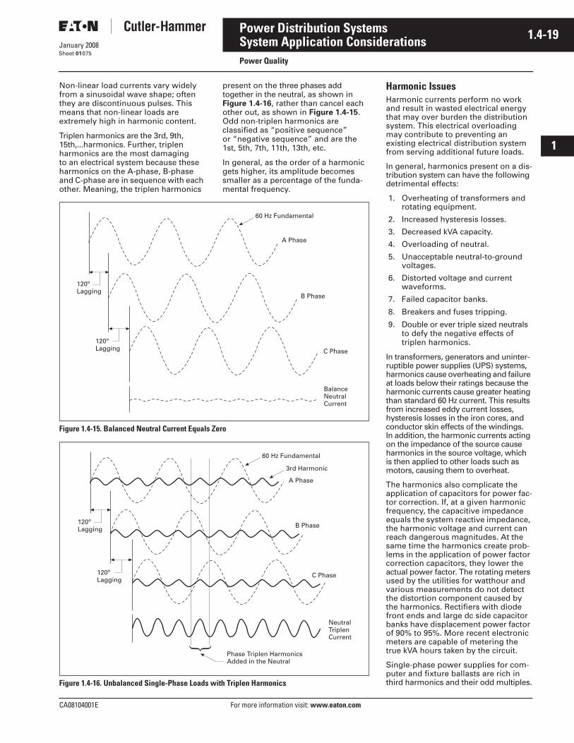
CA08104001E For more information visit: www.eaton.com
1.4-19January 2008
Power Distribution Systems
i
ii
1
2
3
4
5
6
7
8
9
10
11
12
13
14
15
16
17
18
19
20
21
Sheet 01
System Application ConsiderationsPower Quality
075
Non-linear load currents vary widely from a sinusoidal wave shape; often they are discontinuous pulses. This means that non-linear loads are extremely high in harmonic content.
Triplen harmonics are the 3rd, 9th, 15th,...harmonics. Further, triplen harmonics are the most damaging to an electrical system because these harmonics on the A-phase, B-phase and C-phase are in sequence with each other. Meaning, the triplen harmonics
present on the three phases add together in the neutral, as shown in Figure 1.4-16, rather than cancel each other out, as shown in Figure 1.4-15. Odd non-triplen harmonics are classified as “positive sequence” or “negative sequence” and are the 1st, 5th, 7th, 11th, 13th, etc.
In general, as the order of a harmonic gets higher, its amplitude becomes smaller as a percentage of the funda-mental frequency.
Figure 1.4-15. Balanced Neutral Current Equals Zero
Figure 1.4-16. Unbalanced Single-Phase Loads with Triplen Harmonics
A Phase
B Phase
C Phase
60 Hz Fundamental
BalanceNeutralCurrent
120ºLagging
120ºLagging
A Phase
B Phase
C Phase
60 Hz Fundamental
NeutralTriplenCurrent
120ºLagging
120ºLagging
3rd Harmonic
Phase Triplen HarmonicsAdded in the Neutral
Harmonic IssuesHarmonic currents perform no work and result in wasted electrical energy that may over burden the distribution system. This electrical overloading may contribute to preventing an existing electrical distribution system from serving additional future loads.
In general, harmonics present on a dis-tribution system can have the following detrimental effects:
1. Overheating of transformers and rotating equipment.
2. Increased hysteresis losses.
3. Decreased kVA capacity.
4. Overloading of neutral.
5. Unacceptable neutral-to-ground voltages.
6. Distorted voltage and current waveforms.
7. Failed capacitor banks.
8. Breakers and fuses tripping.
9. Double or ever triple sized neutrals to defy the negative effects of triplen harmonics.
In transformers, generators and uninter-ruptible power supplies (UPS) systems, harmonics cause overheating and failure at loads below their ratings because the harmonic currents cause greater heating than standard 60 Hz current. This results from increased eddy current losses, hysteresis losses in the iron cores, and conductor skin effects of the windings. In addition, the harmonic currents acting on the impedance of the source cause harmonics in the source voltage, which is then applied to other loads such as motors, causing them to overheat.
The harmonics also complicate the application of capacitors for power fac-tor correction. If, at a given harmonic frequency, the capacitive impedance equals the system reactive impedance, the harmonic voltage and current can reach dangerous magnitudes. At the same time the harmonics create prob-lems in the application of power factor correction capacitors, they lower the actual power factor. The rotating meters used by the utilities for watthour and various measurements do not detect the distortion component caused by the harmonics. Rectifiers with diode front ends and large dc side capacitor banks have displacement power factor of 90% to 95%. More recent electronic meters are capable of metering the true kVA hours taken by the circuit.
Single-phase power supplies for com-puter and fixture ballasts are rich in third harmonics and their odd multiples.
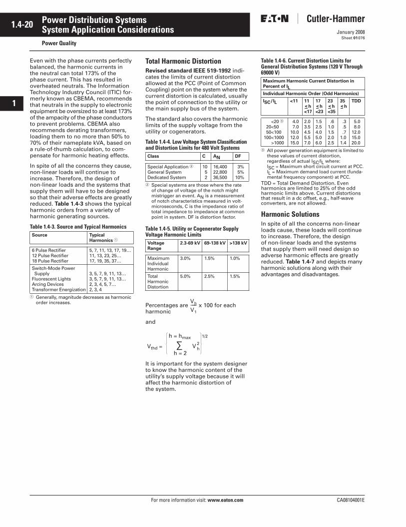
1.4-20
For more information visit: www.eaton.com CA08104001E
January 2008
Power Distribution Systems
i
ii
1
2
3
4
5
6
7
8
9
10
11
12
13
14
15
16
17
18
19
20
21
Sheet 01
System Application ConsiderationsPower Quality
076
Even with the phase currents perfectly balanced, the harmonic currents in the neutral can total 173% of the phase current. This has resulted in overheated neutrals. The Information Technology Industry Council (ITIC) for-merly known as CBEMA, recommends that neutrals in the supply to electronic equipment be oversized to at least 173% of the ampacity of the phase conductors to prevent problems. CBEMA also recommends derating transformers, loading them to no more than 50% to 70% of their nameplate kVA, based on a rule-of-thumb calculation, to com-pensate for harmonic heating effects.
In spite of all the concerns they cause, non-linear loads will continue to increase. Therefore, the design of non-linear loads and the systems that supply them will have to be designed so that their adverse effects are greatly reduced. Table 1.4-3 shows the typical harmonic orders from a variety of harmonic generating sources.
Table 1.4-3. Source and Typical Harmonics
� Generally, magnitude decreases as harmonic order increases.
Total Harmonic DistortionRevised standard IEEE 519-1992 indi-cates the limits of current distortion allowed at the PCC (Point of Common Coupling) point on the system where the current distortion is calculated, usually the point of connection to the utility or the main supply bus of the system.
The standard also covers the harmonic limits of the supply voltage from the utility or cogenerators.
Table 1.4-4. Low Voltage System Classification and Distortion Limits for 480 Volt Systems
� Special systems are those where the rate of change of voltage of the notch might mistrigger an event. AN is a measurement of notch characteristics measured in volt-microseconds, C is the impedance ratio of total impedance to impedance at common point in system. DF is distortion factor.
Table 1.4-5. Utility or Cogenerator Supply Voltage Harmonic Limits
Percentages are x 100 for each harmonic
and
It is important for the system designer to know the harmonic content of the utility’s supply voltage because it will affect the harmonic distortion of the system.
Table 1.4-6. Current Distortion Limits for General Distribution Systems (120 V Through 69000 V)
� All power generation equipment is limited to these values of current distortion, regardless of actual ISC/IL where:ISC = Maximum short circuit current at PCC.IL = Maximum demand load current (funda-mental frequency component) at PCC.
TDD = Total Demand Distortion. Even harmonics are limited to 25% of the odd harmonic limits above. Current distortions that result in a dc offset, e.g., half-wave converters, are not allowed.
Harmonic SolutionsIn spite of all the concerns non-linear loads cause, these loads will continue to increase. Therefore, the design of non-linear loads and the systems that supply them will need design so adverse harmonic effects are greatly reduced. Table 1.4-7 and depicts many harmonic solutions along with their advantages and disadvantages.
Source Typical Harmonics �
6 Pulse Rectifier12 Pulse Rectifier18 Pulse Rectifier
5, 7, 11, 13, 17, 19…11, 13, 23, 25…17, 19, 35, 37…
Switch-Mode Power SupplyFluorescent LightsArcing DevicesTransformer Energization
3, 5, 7, 9, 11, 13…3, 5, 7, 9, 11, 13…2, 3, 4, 5, 7…2, 3, 4
Class C AN DF
Special Application �General SystemDedicated System
10 5 2
16,40022,80036,500
3% 5%10%
Voltage Range
2.3-69 kV 69-138 kV >138 kV
MaximumIndividualHarmonic
3.0% 1.5% 1.0%
TotalHarmonicDistortion
5.0% 2.5% 1.5%
Vh
V1
−−−−
Vthd =
h = hmax
h = 2V 2
h
1/2
∑
Maximum Harmonic Current Distortion in Percent of IL
Individual Harmonic Order (Odd Harmonics)
ISC/IL <11 11h
<17
17h
<23
23h
<35
35h
TDD
<20 �20<5050<100
100<1000>1000
4.0 7.010.012.015.0
2.03.54.55.57.0
1.52.54.05.06.0
.61.01.52.02.5
.3 .5 .71.01.4
5.0 8.012.015.020.0
< < < <
CA08104001E For more information visit: www.eaton.com
1.4-21January 2008
Power Distribution Systems
i
ii
1
2
3
4
5
6
7
8
9
10
11
12
13
14
15
16
17
18
19
20
21
Sheet 01
System Application ConsiderationsPower Quality
077
Table 1.4-7. Harmonic Solutions for Given LoadsLoad Type
Solutions Advantages Disadvantages
Drives and Rectifiers —Includes 3-Phase UPS Loads
Line Reactors ■ Inexpensive.■ For 6-pulse standard drive/rectifier, can
reduce harmonic current distortion from80% down to about 35 – 40%.
■ May require additional compensation.
K-Rated/Drive Isolation Transformer
■ Offers series reactance (similar to line reactors) and provides isolation for some transients.
■ No advantage over reactors for reducing harmonics unless in pairs for shifting phases.
dc Choke ■ Slightly better than ac line reactors for 5th and 7th harmonics.
■ Not always an option for drives.■ Less protection for input semiconductors.
12-Pulse Convertor ■ 85% reduction versus standard 6-pulse drives.
■ Cost difference approaches 18-pulse drive and blocking filters, which guarantee IEEE 519 compliance.
Harmonic Mitigating Transformers/Phase Shifting
■ Substantial (50% – 80%) reduction in harmonics when used in tandem.
■ Harmonic cancellation highly dependent on load balance.
■ Must have even multiples of matched loads.
Tuned Filters ■ Bus connected — accommodates load diversity.
■ Provides PF correction.
■ Requires allocation analysis.■ Sized only to the requirements of that system.
Must be resized if system changes.
Broadband Filters ■ Makes 6-pulse into the equivalent of 18-pulse.
■ Higher cost.■ Requires one filter per drive.
18-Pulse Converter ■ Excellent harmonic control for drives above 100 hp.
■ IEEE 519 compliant.
■ High cost.
Active Filters ■ Handles load/harmonic diversity.■ Complete solution up to 50th harmonic.
■ High cost.
Computers/Switch-Mode Power Supplies
Neutral Blocking Filter ■ Eliminates the 3rd harmonic from load.■ Relieves system capacity.■ Possible energy savings.
■ High cost.■ May increase voltage distortion.
Harmonic Mitigating Transformers
■ 3rd harmonic recalculated back to the load.■ When used as phase-shifted transformers,
reduces other harmonics.■ Reduces voltage “flat-topping”.
■ Requires fully rated circuits and oversized neutrals to the loads.
Oversized Neutral/Derated Transformer
■ Tolerate harmonics rather than correct.■ Typically least expensive.
■ Upstream and downstream equipment fully rated for harmonics.
K-Rated Transformer ■ Tolerate harmonics rather than correct. ■ Does not reduce system harmonics.
Fluorescent Lighting
Harmonic Mitigating Transformers
■ 3rd harmonic recalculated back to the load.■ When used as phase-shifted transformers,
reduces other harmonics.■ Reduces voltage “flat-topping”.
■ Requires fully rated circuits and oversized neutrals to the loads.
K-Rated Transformer ■ Tolerate harmonics rather than correct them. ■ Does not reduce system harmonics.
Low Distortion Ballasts ■ Reduce harmonics at the source. ■ Additional cost and typically more expensive than “system” solutions.
Welding/Arcing Loads
Active Filters ■ Fast response and broadband harmonic correction.
■ Reduces voltage flicker.
■ High cost.
Tuned Filters ■ SCR controlled tuned filters simulates an active filter response.
■ SCR controlled units are high cost but fixed filters are reasonable.
System Solutions
Tuned Filters ■ Provides PF correction.■ Lower cost compared to other systems.
■ System analysis required to verify application.Must be resized if system changes.
Harmonic Mitigating Transformers
■ Excellent choice for new design or upgrade.
■ No PF correction benefit.
Active Filters ■ Ideal solution and handles system diversity.
■ Highest cost.
1.4-22
For more information visit: www.eaton.com CA08104001E
January 2008
Power Distribution Systems
i
ii
1
2
3
4
5
6
7
8
9
10
11
12
13
14
15
16
17
18
19
20
21
Sheet 01
Uninterruptible Power Systems (UPS)078
5. Uninterruptible Power Systems (UPS)The advent of solid-state semiconduc-tors over 40 years ago, and their subsequent evolution to transistors, and the miniaturization of electronics into microprocessor over 25 years ago, has created numerous computation machines that assist us in every con-ceivable manner. These machines, and their clever configurations, whether they take the form of comput-ers, appliance controls, fax machines, phone systems, computers of all sizes, server systems and server farms, emergency call centers, data processing at banks, credit companies, private company communication net-works, government institutions, and defense agencies all rely on a narrow range of nominal ac power in order for these devices to work properly. Indeed, many other types of equip-ment also require that the ac electrical power source be at or close to nominal voltage and frequency. Disturbances of the power translate into failed processes, lost data, decreased efficiency and lost revenue.
The normal power source supplied by the local utility or provider is not stable enough over time to continuously serve these loads without interruption. It is possible that a facility outside a major metropolitan area served by the utility grid will experience outages of some nature 15 – 20 times in one year. Certain outages are caused by the weather, and others by the failure of the utility supply system due to equipment failures or construction interruptions. Some outages are only several cycles in duration, while others may be for hours at a time.
In a broader sense, other problems exist in the area of power quality, and many of those issues also contribute to the failure of the supply to provide that narrow range of power to the sensitive loads mentioned above. Power Quality problems take the form of any of the following: power failure, power sag, power surge, undervoltage, overvoltage, line noise, frequency variations, switching transients, and harmonic distortion. Regardless of the reason for outages and power quality problems, the sensi-tive loads can not function normally without a backup power source and in many cases the loads must be isolated from the instabilities of the utility sup-ply and power quality problems and given clean reliable power on a contin-uous basis, or be able to switch over to reliable clean electrical power quickly.
Uninterruptible Power Supply (UPS) systems have evolved to serve the needs of sensitive equipment and can supply a stable source of electrical power, or switch to backup to allow for an orderly shutdown of the loads without appreciable loss of data or process. In the early days of main-frame computers, motor-generator sets provide isolation and clean power to the computers. They did not have deep reserves, but provided extensive ride-through capability while other sources of power (usually standby emergency engine generator sets) were brought to bear to serve the motor-generator sets while the normal source of power was unstable or unavailable.
UPS systems have evolved along the lines of rotary types and static types of systems, and they come in many con-figurations, and even hybrid designs having characteristics of both types. The discussion that follows attempts to compare and contrast the two types of UPS systems, and give basic guidance on selection criteria. This discussion will focus on the medium, large and very large UPS systems required by users who need more than 10 kVA of clean reliable power.
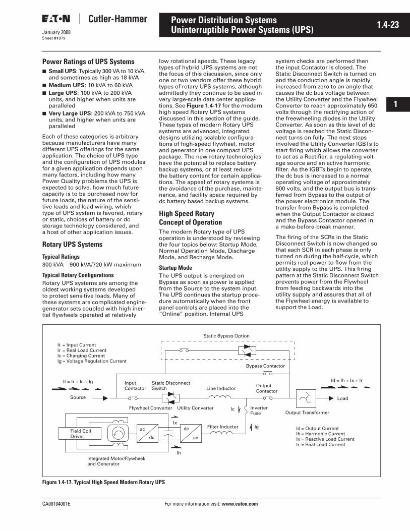
CA08104001E For more information visit: www.eaton.com
1.4-23January 2008
Power Distribution Systems
i
ii
1
2
3
4
5
6
7
8
9
10
11
12
13
14
15
16
17
18
19
20
21
Sheet 01
Uninterruptible Power Systems (UPS)079
Power Ratings of UPS Systems■ Small UPS: Typically 300 VA to 10 kVA,
and sometimes as high as 18 kVA■ Medium UPS: 10 kVA to 60 kVA■ Large UPS: 100 kVA to 200 kVA
units, and higher when units are paralleled
■ Very Large UPS: 200 kVA to 750 kVA units, and higher when units are paralleled
Each of these categories is arbitrary because manufacturers have many different UPS offerings for the same application. The choice of UPS type and the configuration of UPS modules for a given application depends upon many factors, including how many Power Quality problems the UPS is expected to solve, how much future capacity is to be purchased now for future loads, the nature of the sensi-tive loads and load wiring, which type of UPS system is favored, rotary or static, choices of battery or dc storage technology considered, and a host of other application issues.
Rotary UPS Systems
Typical Ratings300 kVA – 900 kVA/720 kW maximum
Typical Rotary ConfigurationsRotary UPS systems are among the oldest working systems developed to protect sensitive loads. Many of these systems are complicated engine-generator sets coupled with high iner-tial flywheels operated at relatively
low rotational speeds. These legacy types of hybrid UPS systems are not the focus of this discussion, since only one or two vendors offer these hybrid types of rotary UPS systems, although admittedly they continue to be used in very large-scale data center applica-tions. See Figure 1.4-17 for the modern high speed Rotary UPS systems discussed in this section of the guide. These types of modern Rotary UPS systems are advanced, integrated designs utilizing scalable configura-tions of high-speed flywheel, motor and generator in one compact UPS package. The new rotary technologies have the potential to replace battery backup systems, or at least reduce the battery content for certain applica-tions. The appeal of rotary systems is the avoidance of the purchase, mainte-nance, and facility space required by dc battery based backup systems.
High Speed Rotary Concept of OperationThe modern Rotary type of UPS operation is understood by reviewing the four topics below: Startup Mode, Normal Operation Mode, Discharge Mode, and Recharge Mode.
Startup ModeThe UPS output is energized on Bypass as soon as power is applied from the Source to the system input. The UPS continues the startup proce-dure automatically when the front panel controls are placed into the “Online” position. Internal UPS
system checks are performed then the input Contactor is closed. The Static Disconnect Switch is turned on and the conduction angle is rapidly increased from zero to an angle that causes the dc bus voltage between the Utility Converter and the Flywheel Converter to reach approximately 650 volts through the rectifying action of the freewheeling diodes in the Utility Converter. As soon as this level of dc voltage is reached the Static Discon-nect turns on fully. The next steps involved the Utility Converter IGBTs to start firing which allows the converter to act as a Rectifier, a regulating volt-age source and an active harmonic filter. As the IGBTs begin to operate, the dc bus is increased to a normal operating voltage of approximately 800 volts, and the output bus is trans-ferred from Bypass to the output of the power electronics module. The transfer from Bypass is completed when the Output Contactor is closed and the Bypass Contactor opened in a make-before-break manner.
The firing of the SCRs in the Static Disconnect Switch is now changed so that each SCR in each phase is only turned on during the half-cycle, which permits real power to flow from the utility supply to the UPS. This firing pattern at the Static Disconnect Switch prevents power from the Flywheel from feeding backwards into the utility supply and assures that all of the Flywheel energy is available to support the Load.
Figure 1.4-17. Typical High Speed Modern Rotary UPS
It = Ir + Ic + Ig
Id = Output CurrentIh = Harmonic CurrentIx = Reactive Load CurrentIr = Real Load Current
Source
Field CoilDriver
Integrated Motor/Flywheel/and Generator
ac
dc
dc
ac
Ih
Ix
Flywheel Converter Utility Converter Ic
IgFilter Inductor
InverterFuse
Line Inductor OutputContactor
InputContactor
Static DisconnectSwitch
Bypass Contactor
Static Bypass Option
Load
Output Transformer
Id = Ih + Ix + Ir
It = Input CurrentIr = Real Load CurrentIc = Charging CurrentIg = Voltage Regulation Current
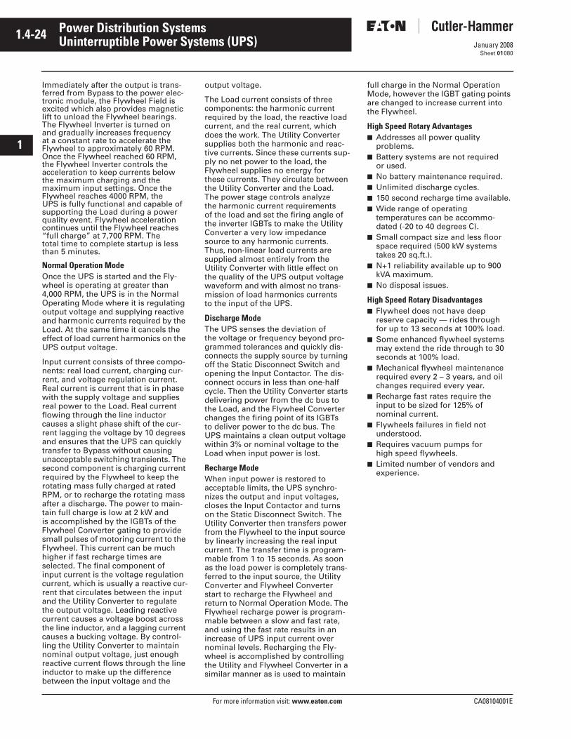
1.4-24
For more information visit: www.eaton.com CA08104001E
January 2008
Power Distribution Systems
i
ii
1
2
3
4
5
6
7
8
9
10
11
12
13
14
15
16
17
18
19
20
21
Sheet 01
Uninterruptible Power Systems (UPS)080
Immediately after the output is trans-ferred from Bypass to the power elec-tronic module, the Flywheel Field is excited which also provides magnetic lift to unload the Flywheel bearings. The Flywheel Inverter is turned on and gradually increases frequency at a constant rate to accelerate the Flywheel to approximately 60 RPM. Once the Flywheel reached 60 RPM, the Flywheel Inverter controls the acceleration to keep currents below the maximum charging and the maximum input settings. Once the Flywheel reaches 4000 RPM, the UPS is fully functional and capable of supporting the Load during a power quality event. Flywheel acceleration continues until the Flywheel reaches “full charge” at 7,700 RPM. The total time to complete startup is less than 5 minutes.
Normal Operation ModeOnce the UPS is started and the Fly-wheel is operating at greater than 4,000 RPM, the UPS is in the Normal Operating Mode where it is regulating output voltage and supplying reactive and harmonic currents required by the Load. At the same time it cancels the effect of load current harmonics on the UPS output voltage.
Input current consists of three compo-nents: real load current, charging cur-rent, and voltage regulation current. Real current is current that is in phase with the supply voltage and supplies real power to the Load. Real current flowing through the line inductor causes a slight phase shift of the cur-rent lagging the voltage by 10 degrees and ensures that the UPS can quickly transfer to Bypass without causing unacceptable switching transients. The second component is charging current required by the Flywheel to keep the rotating mass fully charged at rated RPM, or to recharge the rotating mass after a discharge. The power to main-tain full charge is low at 2 kW and is accomplished by the IGBTs of the Flywheel Converter gating to provide small pulses of motoring current to the Flywheel. This current can be much higher if fast recharge times are selected. The final component of input current is the voltage regulation current, which is usually a reactive cur-rent that circulates between the input and the Utility Converter to regulate the output voltage. Leading reactive current causes a voltage boost across the line inductor, and a lagging current causes a bucking voltage. By control-ling the Utility Converter to maintain nominal output voltage, just enough reactive current flows through the line inductor to make up the difference between the input voltage and the
output voltage.
The Load current consists of three components: the harmonic current required by the load, the reactive load current, and the real current, which does the work. The Utility Converter supplies both the harmonic and reac-tive currents. Since these currents sup-ply no net power to the load, the Flywheel supplies no energy for these currents. They circulate between the Utility Converter and the Load. The power stage controls analyze the harmonic current requirements of the load and set the firing angle of the inverter IGBTs to make the Utility Converter a very low impedance source to any harmonic currents. Thus, non-linear load currents are supplied almost entirely from the Utility Converter with little effect on the quality of the UPS output voltage waveform and with almost no trans-mission of load harmonics currents to the input of the UPS.
Discharge ModeThe UPS senses the deviation of the voltage or frequency beyond pro-grammed tolerances and quickly dis-connects the supply source by turning off the Static Disconnect Switch and opening the Input Contactor. The dis-connect occurs in less than one-half cycle. Then the Utility Converter starts delivering power from the dc bus to the Load, and the Flywheel Converter changes the firing point of its IGBTs to deliver power to the dc bus. The UPS maintains a clean output voltage within 3% or nominal voltage to the Load when input power is lost.
Recharge ModeWhen input power is restored to acceptable limits, the UPS synchro-nizes the output and input voltages, closes the Input Contactor and turns on the Static Disconnect Switch. The Utility Converter then transfers power from the Flywheel to the input source by linearly increasing the real input current. The transfer time is program-mable from 1 to 15 seconds. As soon as the load power is completely trans-ferred to the input source, the Utility Converter and Flywheel Converter start to recharge the Flywheel and return to Normal Operation Mode. The Flywheel recharge power is program-mable between a slow and fast rate, and using the fast rate results in an increase of UPS input current over nominal levels. Recharging the Fly-wheel is accomplished by controlling the Utility and Flywheel Converter in a similar manner as is used to maintain
full charge in the Normal Operation Mode, however the IGBT gating points are changed to increase current into the Flywheel.
High Speed Rotary Advantages■ Addresses all power quality
problems.■ Battery systems are not required
or used.■ No battery maintenance required.■ Unlimited discharge cycles.■ 150 second recharge time available.■ Wide range of operating
temperatures can be accommo-dated (-20 to 40 degrees C).
■ Small compact size and less floor space required (500 kW systems takes 20 sq.ft.).
■ N+1 reliability available up to 900 kVA maximum.
■ No disposal issues.
High Speed Rotary Disadvantages■ Flywheel does not have deep
reserve capacity — rides through for up to 13 seconds at 100% load.
■ Some enhanced flywheel systems may extend the ride through to 30 seconds at 100% load.
■ Mechanical flywheel maintenance required every 2 – 3 years, and oil changes required every year.
■ Recharge fast rates require the input to be sized for 125% of nominal current.
■ Flywheels failures in field not understood.
■ Requires vacuum pumps for high speed flywheels.
■ Limited number of vendors and experience.
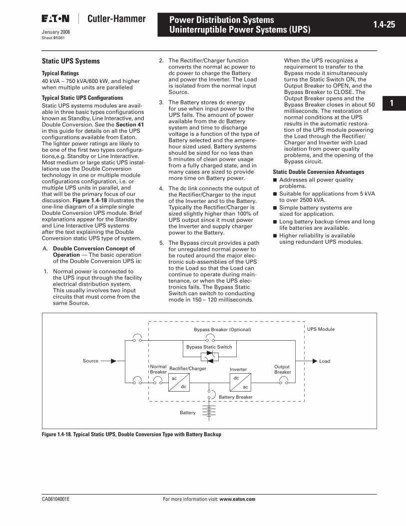
CA08104001E For more information visit: www.eaton.com
1.4-25January 2008
Power Distribution Systems
i
ii
1
2
3
4
5
6
7
8
9
10
11
12
13
14
15
16
17
18
19
20
21
Sheet 01
Uninterruptible Power Systems (UPS)081
Static UPS Systems
Typical Ratings40 kVA – 750 kVA/600 kW, and higher when multiple units are paralleled
Typical Static UPS ConfigurationsStatic UPS systems modules are avail-able in three basic types configurations known as Standby, Line Interactive, and Double Conversion. See the Section 41 in this guide for details on all the UPS configurations available from Eaton. The lighter power ratings are likely to be one of the first two types configura-tions,e.g. Standby or Line Interactive. Most medium or large static UPS instal-lations use the Double Conversion technology in one or multiple module configurations configuration, i.e. or multiple UPS units in parallel, and that will be the primary focus of our discussion. Figure 1.4-18 illustrates the one-line diagram of a simple single Double Conversion UPS module. Brief explanations appear for the Standby and Line Interactive UPS systems after the text explaining the Double Conversion static UPS type of system.
A. Double Conversion Concept of Operation — The basic operation of the Double Conversion UPS is:
1. Normal power is connected to the UPS input through the facility electrical distribution system. This usually involves two input circuits that must come from the same Source.
2. The Rectifier/Charger function converts the normal ac power to dc power to charge the Battery and power the Inverter. The Load is isolated from the normal input Source.
3. The Battery stores dc energy for use when input power to the UPS fails. The amount of power available from the dc Battery system and time to discharge voltage is a function of the type of Battery selected and the ampere-hour sized used. Battery systems should be sized for no less than 5 minutes of clean power usage from a fully charged state, and in many cases are sized to provide more time on Battery power.
4. The dc link connects the output of the Rectifier/Charger to the input of the Inverter and to the Battery. Typically the Rectifier/Charger is sized slightly higher than 100% of UPS output since it must power the Inverter and supply charger power to the Battery.
5. The Bypass circuit provides a path for unregulated normal power to be routed around the major elec-tronic sub-assemblies of the UPS to the Load so that the Load can continue to operate during main-tenance, or when the UPS elec-tronics fails. The Bypass Static Switch can switch to conducting mode in 150 – 120 milliseconds.
When the UPS recognizes a requirement to transfer to the Bypass mode it simultaneously turns the Static Switch ON, the Output Breaker to OPEN, and the Bypass Breaker to CLOSE. The Output Breaker opens and the Bypass Breaker closes in about 50 milliseconds. The restoration of normal conditions at the UPS results in the automatic restora-tion of the UPS module powering the Load through the Rectifier/Charger and Inverter with Load isolation from power quality problems, and the opening of the Bypass circuit.
Static Double Conversion Advantages■ Addresses all power quality
problems.■ Suitable for applications from 5 kVA
to over 2500 kVA.■ Simple battery systems are
sized for application.■ Long battery backup times and long
life batteries are available.■ Higher reliability is available
using redundant UPS modules.
Figure 1.4-18. Typical Static UPS, Double Conversion Type with Battery Backup
Source
Battery
ac
dc
dc
ac
Inverter OutputBreaker
NormalBreaker
Bypass Static Switch
UPS Module
Load
Rectifier/Charger
Battery Breaker
Bypass Breaker (Optional)
1.4-26
For more information visit: www.eaton.com CA08104001E
January 2008
Power Distribution Systems
i
ii
1
2
3
4
5
6
7
8
9
10
11
12
13
14
15
16
17
18
19
20
21
Sheet 01
Uninterruptible Power Systems (UPS)082
Static Double Conversion Disadvantages■ Battery systems, battery maintenance,
and battery replacement are required.■ Large space requirement for
battery systems (higher life takes more space, e.g., 500 kW takes 80 to 200 sq.ft. depending upon the type of battery used, VRLA 10 year, VRLA 20 year or flooded).
■ Limited discharge cycles of battery system.
■ Narrow temperature range for application.
■ Efficiencies are in the 90 – 94% range, which is lower than some line interactive configurations.
■ Bypass mode places load at risk unless bypass has UPS backup.
■ Redundancy of UPS modules results in higher costs.
■ Output faults are cleared by the bypass circuit.
■ Output rating of the UPS is 150% for 30 seconds.
■ Battery disposal and safety issues exist.
B. Standby UPS Concept of Operation — The basic operation of the Standby UPS is:
1. The Standby UPS topology is similar to the Double Conversion type, but the operation of the UPS is different in significant ways. Normal power is connected to the UPS input through the facility electrical distribution system. This usually involves two input circuits that must come from the same Source. See Figure 1.4-19 for details.
2. The Rectifier/Charger function converts the normal ac power to dc power to charge the Battery only and does not simultaneously power the Inverter. The Load is connected to the input source through the Bypass static switch. The Inverter is in the standby mode ready to serve the load from Battery power if the input power source fails.
3. The Battery stores dc energy for use by the Inverter when input power to the UPS fails. The amount of power available from the dc Battery system and time to discharge voltage is a function of the type of Battery selected and the ampere-hour sized used. Battery systems should be sized for the anticipated outage.
4. The dc link connects the output of the Rectifier/Charger to the input of the Inverter and to the Battery. Typically the Rectifier/Charger is sized only to supply charger power to the Battery, and is rated far lower than in the Double Conversion UPS.
5. The Bypass circuit provides a direct connection of input source to the Load. The Load operates from unregulated power. The Bypass Static Switch can switch to non-conducting mode in 150 – 120 milliseconds. When the UPS recognizes the loss of normal input power it transfers to Battery /Inverter mode by simultaneously turning the Inverter ON and the Static Switch OFF.
Static Standby UPS Advantages■ Lower costs than double conversion.■ Rectifier and charger are
economically sized.■ Efficient design.■ Batteries are sized for the
application.
Static Standby UPS Disadvantages■ Impractical over 2 kVA.■ Little to no isolation of load from
power quality disturbances.■ Standby power is from battery
alone.■ Battery systems, battery mainte-
nance, and battery replacement are required.
■ Limited discharge cycles of battery system.
■ Narrow temperature range for application.
■ Output faults are cleared by the bypass circuit.
■ Battery disposal and safety issues exist.
C. Static Line Interactive UPS Concept of Operation — The basic operation of the Line Interactive UPS is:
1. The Line Interactive type of UPS has a different topology than the Static Double Conversion and Standby systems. The normal input power is connected to the Load in Parallel with a Battery and bi-directional Inverter/Charger assembly. The input source usu-ally terminates at a line inductor and the output of the inductor is connected to the Load in parallel with the Battery and Inverter/Charger circuit. See Figure 1.4-20 for further details.
2. The traditional Rectifier circuit is eliminated and this results in a smaller footprint and weight reduction. However, line condi-tioning is compromised.
3. When the input power fails, the Battery/Inverter Charger circuit reverses power and supplies the Load with regulated power.
Static Line Interactive UPS Advantages■ Slight improvement of power condi-
tioning over Standby UPS systems.■ Small footprints and weights.■ Efficient design.■ Batteries are sized for the
application.
Static Line Interactive UPS Disadvantages■ Impractical over 5 kVA.■ Not as good conditioning as
double conversion.■ Standby power is from battery alone.■ Battery systems, battery mainte-
nance, and battery replacement are required.
■ Limited discharge cycles for the battery system.
■ Narrow temperature range for application.
■ Battery disposal and safety issues exist.

CA08104001E For more information visit: www.eaton.com
1.4-27January 2008
Power Distribution Systems
i
ii
1
2
3
4
5
6
7
8
9
10
11
12
13
14
15
16
17
18
19
20
21
Sheet 01
Uninterruptible Power Systems (UPS)083
Figure 1.4-19. Typical Static UPS, Standby Type with Battery Backup
Figure 1.4-20. Typical Static UPS, Line Interactive Type with Battery Backup
Source
ac
dc
dc
ac
UPS Module
Normal Breaker
Rectifier/Charger Inverter
Bypass Static Switch
Battery Breaker
OutputBreaker
Battery
Load
Source
dc
ac
UPS Module
Bidirectional Inverter/Charger
Battery
Load
Inductor
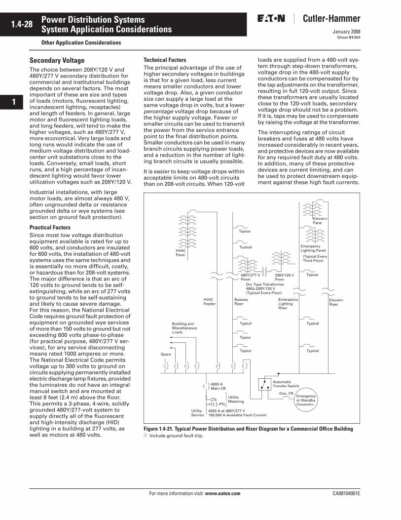
1.4-28
For more information visit: www.eaton.com CA08104001E
January 2008
Power Distribution Systems
i
ii
1
2
3
4
5
6
7
8
9
10
11
12
13
14
15
16
17
18
19
20
21
Sheet 01
System Application ConsiderationsOther Application Considerations
084
Secondary VoltageThe choice between 208Y/120 V and 480Y/277 V secondary distribution for commercial and institutional buildings depends on several factors. The most important of these are size and types of loads (motors, fluorescent lighting, incandescent lighting, receptacles) and length of feeders. In general, large motor and fluorescent lighting loads, and long feeders, will tend to make the higher voltages, such as 480Y/277 V, more economical. Very large loads and long runs would indicate the use of medium voltage distribution and load-center unit substations close to the loads. Conversely, small loads, short runs, and a high percentage of incan-descent lighting would favor lower utilization voltages such as 208Y/120 V.
Industrial installations, with large motor loads, are almost always 480 V, often ungrounded delta or resistance grounded delta or wye systems (see section on ground fault protection).
Practical FactorsSince most low voltage distribution equipment available is rated for up to 600 volts, and conductors are insulated for 600 volts, the installation of 480-volt systems uses the same techniques and is essentially no more difficult, costly, or hazardous than for 208-volt systems. The major difference is that an arc of 120 volts to ground tends to be self-extinguishing, while an arc of 277 volts to ground tends to be self-sustaining and likely to cause severe damage. For this reason, the National Electrical Code requires ground fault protection of equipment on grounded wye services of more than 150 volts to ground but not exceeding 600 volts phase-to-phase (for practical purpose, 480Y/277 V ser-vices), for any service disconnecting means rated 1000 amperes or more. The National Electrical Code permits voltage up to 300 volts to ground on circuits supplying permanently installed electric discharge lamp fixtures, provided the luminaires do not have an integral manual switch and are mounted at least 8 feet (2.4 m) above the floor. This permits a 3-phase, 4-wire, solidly grounded 480Y/277-volt system to supply directly all of the fluorescent and high-intensity discharge (HID) lighting in a building at 277 volts, as well as motors at 480 volts.
Technical FactorsThe principal advantage of the use of higher secondary voltages in buildings is that for a given load, less current means smaller conductors and lower voltage drop. Also, a given conductor size can supply a large load at the same voltage drop in volts, but a lower percentage voltage drop because of the higher supply voltage. Fewer or smaller circuits can be used to transmit the power from the service entrance point to the final distribution points. Smaller conductors can be used in many branch circuits supplying power loads, and a reduction in the number of light-ing branch circuits is usually possible.
It is easier to keep voltage drops within acceptable limits on 480-volt circuits than on 208-volt circuits. When 120-volt
loads are supplied from a 480-volt sys-tem through step-down transformers, voltage drop in the 480-volt supply conductors can be compensated for by the tap adjustments on the transformer, resulting in full 120-volt output. Since these transformers are usually located close to the 120-volt loads, secondary voltage drop should not be a problem. If it is, taps may be used to compensate by raising the voltage at the transformer.
The interrupting ratings of circuit breakers and fuses at 480 volts have increased considerably in recent years, and protective devices are now available for any required fault duty at 480 volts. In addition, many of these protective devices are current limiting, and can be used to protect downstream equip-ment against these high fault currents.
Figure 1.4-21. Typical Power Distribution and Riser Diagram for a Commercial Office Building� Include ground fault trip.
➀
➀
Spare
Building andMiscellaneousLoads
4000 AMain CB
AutomaticTransferTT Switch
TypicaTT l
Gen. CB
V100,000 A Available Fault CurrentAA
UtilitygCTsTT
s
UtilityService
HVACVVFeeder
BuswayRiser
ElevatorRiser
ElevatorPanel
(Typical EveryTTThird Floor)
480Y/277Panel
208Y/120 VPanel
EmergencyLightingRiser
HVACVVPanel
Dry Ty480∆-208Y/120 V(Typical Every Floor)TT
EmergencyLighting Panel
TypicaTT l
TypicaTT l
Typical
TypicalTT
TypicalTT
Typical
Typical
Emergencyor StandbyGenerator
➀ ➀ ➀ ➀ ➀ ➀
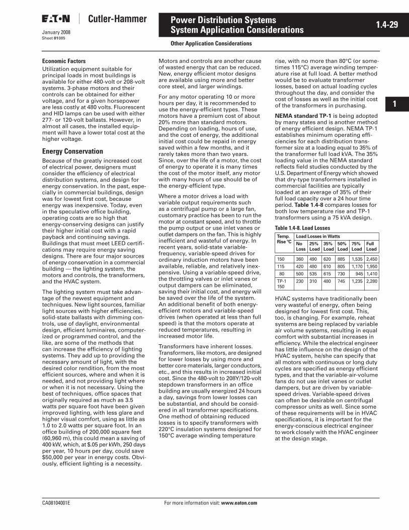
CA08104001E For more information visit: www.eaton.com
1.4-29January 2008
Power Distribution Systems
i
ii
1
2
3
4
5
6
7
8
9
10
11
12
13
14
15
16
17
18
19
20
21
Sheet 01
System Application ConsiderationsOther Application Considerations
085
Economic FactorsUtilization equipment suitable for principal loads in most buildings is available for either 480-volt or 208-volt systems. 3-phase motors and their controls can be obtained for either voltage, and for a given horsepower are less costly at 480 volts. Fluorescent and HID lamps can be used with either 277- or 120-volt ballasts. However, in almost all cases, the installed equip-ment will have a lower total cost at the higher voltage.
Energy ConservationBecause of the greatly increased cost of electrical power, designers must consider the efficiency of electrical distribution systems, and design for energy conservation. In the past, espe-cially in commercial buildings, design was for lowest first cost, because energy was inexpensive. Today, even in the speculative office building, operating costs are so high that energy-conserving designs can justify their higher initial cost with a rapid payback and continuing savings. Buildings that must meet LEED certifi-cations may require energy saving designs. There are four major sources of energy conservation in a commercial building — the lighting system, the motors and controls, the transformers, and the HVAC system.
The lighting system must take advan-tage of the newest equipment and techniques. New light sources, familiar light sources with higher efficiencies, solid-state ballasts with dimming con-trols, use of daylight, environmental design, efficient luminaires, computer-ized or programmed control, and the like, are some of the methods that can increase the efficiency of lighting systems. They add up to providing the necessary amount of light, with the desired color rendition, from the most efficient sources, where and when it is needed, and not providing light where or when it is not necessary. Using the best of techniques, office spaces that originally required as much as 3.5 watts per square foot have been given improved lighting, with less glare and higher visual comfort, using as little as 1.0 to 2.0 watts per square foot. In an office building of 200,000 square feet (60,960 m), this could mean a saving of 400 kW, which, at $.05 per kWh, 250 days per year, 10 hours per day, could save $50,000 per year in energy costs. Obvi-ously, efficient lighting is a necessity.
Motors and controls are another cause of wasted energy that can be reduced. New, energy efficient motor designs are available using more and better core steel, and larger windings.
For any motor operating 10 or more hours per day, it is recommended to use the energy-efficient types. These motors have a premium cost of about 20% more than standard motors. Depending on loading, hours of use, and the cost of energy, the additional initial cost could be repaid in energy saved within a few months, and it rarely takes more than two years. Since, over the life of a motor, the cost of energy to operate it is many times the cost of the motor itself, any motor with many hours of use should be of the energy-efficient type.
Where a motor drives a load with variable output requirements such as a centrifugal pump or a large fan, customary practice has been to run the motor at constant speed, and to throttle the pump output or use inlet vanes or outlet dampers on the fan. This is highly inefficient and wasteful of energy. In recent years, solid-state variable-frequency, variable-speed drives for ordinary induction motors have been available, reliable, and relatively inex-pensive. Using a variable-speed drive, the throttling valves or inlet vanes or output dampers can be eliminated, saving their initial cost, and energy will be saved over the life of the system. An additional benefit of both energy-efficient motors and variable-speed drives (when operated at less than full speed) is that the motors operate at reduced temperatures, resulting in increased motor life.
Transformers have inherent losses. Transformers, like motors, are designed for lower losses by using more and better core materials, larger conductors, etc., and this results in increased initial cost. Since the 480-volt to 208Y/120-volt stepdown transformers in an office building are usually energized 24 hours a day, savings from lower losses can be substantial, and should be consid-ered in all transformer specifications. One method of obtaining reduced losses is to specify transformers with 220°C insulation systems designed for 150°C average winding temperature
rise, with no more than 80°C (or some-times 115°C) average winding temper-ature rise at full load. A better method would be to evaluate transformer losses, based on actual loading cycles throughout the day, and consider the cost of losses as well as the initial cost of the transformers in purchasing.
NEMA standard TP-1 is being adopted by many states and is another method of energy efficient design. NEMA TP-1 establishes minimum operating effi-ciencies for each distribution trans-former size at a loading equal to 35% of the transformer full load kVA. The 35% loading value in the NEMA standard reflects field studies conducted by the U.S. Department of Energy which showed that dry-type transformers installed in commercial facilities are typically loaded at an average of 35% of their full load capacity over a 24 hour time period. Table 1.4-8 compares losses for both low temperature rise and TP-1 transformers using a 75 kVA design.
Table 1.4-8. Load Losses
HVAC systems have traditionally been very wasteful of energy, often being designed for lowest first cost. This, too, is changing. For example, reheat systems are being replaced by variable air volume systems, resulting in equal comfort with substantial increases in efficiency. While the electrical engineer has little influence on the design of the HVAC system, he/she can specify that all motors with continuous or long duty cycles are specified as energy efficient types, and that the variable-air-volume fans do not use inlet vanes or outlet dampers, but are driven by variable-speed drives. Variable-speed drives can often be desirable on centrifugal compressor units as well. Since some of these requirements will be in HVAC specifications, it is important for the energy-conscious electrical engineer to work closely with the HVAC engineer at the design stage.
Temp. Rise ºC
Load Losses in Watts
NoLoss
25%Load
35%Load
50%Load
75% Load
Full Load
150 360 490 620 885 1,535 2,450
115 420 480 610 805 1,170 1,950
80 500 535 615 730 945 1,410
TP-1 150
230 310 480 745 1,235 2,280
1.4-30
For more information visit: www.eaton.com CA08104001E
January 2008
Power Distribution Systems
i
ii
1
2
3
4
5
6
7
8
9
10
11
12
13
14
15
16
17
18
19
20
21
Sheet 01
System Application ConsiderationsOther Application Considerations
086
Building Control SystemsIn order to obtain the maximum benefit from these energy-saving lighting, power, and HVAC systems, they must be controlled to perform their functions most efficiently. Constant monitoring would be required for manual operation, so some form of automatic control is required. The simplest of these energy-saving controls, often very effective, is a time clock to turn various systems on and off. Where flexible control is required, programmable controllers may be used. These range from simple devices, similar to multi-function time clocks, up to full micro-processor-based, fully programmable devices, really small computers. For complete control of all building systems, computers with specialized software can be used. Computers can not only control lighting and HVAC systems, and provide peak demand control, to minimize the cost of energy, but they can perform many other functions. Fire detection and alarm systems can operate through the computer, which can also perform auxiliary functions such as elevator control and building communication in case of fire. Build-ing security systems, such as closed-circuit television monitoring, door alarms, intruder sensing, can be performed by the same building computer system.
The time clocks, programmable controllers, and computers can obtain data from external sensors and control the lighting, motors, and other equipment by means of hard wiring-separate wires to and from each piece of equipment. In the more complex systems, this would result in a tremendous number of control wires, so other methods are frequently used. A single pair of wires, with elec-tronic digital multiplexing, can control or obtain data from many different points. Sometimes, coaxial cable is used with advanced signaling equip-ment. Some systems dispense with control wiring completely, sending and receiving digital signals over the power wiring. The newest systems may use fiber-optic cables to carry tremendous quantities of data, free from electromagnetic interference. The method used will depend on the type, number, and complexity of functions to be performed.
Because building design and control for maximum energy saving is impor-tant and complex, and frequently involves many functions and several systems, it is necessary for the design engineer to make a thorough building and environmental study, and to weigh the costs and advantages of many systems. The result of good design can be economical, efficient operation. Poor design can be wasteful, and extremely costly.
CogenerationCogeneration is another outgrowth of the high cost of energy. Cogeneration is the production of electric power concurrently with the production of steam, hot water, and similar energy uses. The electric power can be the main product, and steam or hot water the by-product, as in most commercial installations, or the steam or hot water can be the most required product, and electric power a by-product, as in many industrial installations. In some industries, cogeneration has been common practice for many years, but until recently it has not been economi-cally feasible for most commercial installations. This has been changed by the high cost of purchased energy, plus a federal law (Public Utility Regu-latory Policies Act, known as PURPA) that requires public utilities to purchase any excess power generated by the cogeneration plant. In many cases, practical commercial cogeneration systems have been built that provide some or all of the electric power required, plus hot water, steam, and sometimes steam absorption-type air conditioning. Such cogeneration systems are now operating success-fully in hospitals, shopping centers, high-rise apartment buildings and even commercial office buildings.
Where a cogeneration system is being considered, the electrical distribution system becomes more complex. The interface with the utility company is criti-cal, requiring careful relaying to protect both the utility and the cogeneration system. Many utilities have stringent requirements that must be incorporated into the system. Proper generator con-trol and protection is necessary, as well. An on-site electrical generating plant tied to an electrical utility, is a sophisti-cated engineering design.
Utilities require that when the protective device at their substation opens that the device connecting a cogenerator to the utility open also.
One reason is that most cogenerators are connected to feeders serving other customers. Utilities desire to reclose the feeder after a transient fault is cleared. Reclosing in most cases will damage the cogenerator if it had remained connected to their system.
Islanding is another reason why the utility insists on the disconnection of the cogenerator. Islanding is the event that after a fault in the utility’s system is cleared by the operation of the protective devices, a part of the system may continue to be supplied by cogeneration. Such a condition is dangerous to the utility’s operation during restoration work.
Major cogenerators are connected to the subtransmission or the transmission system of a utility. Major cogenerators have buy-sell agreements. In such cases utilities use a trip transfer scheme to trip the cogenerator breaker.
Guidelines that are given in ANSI Guide Standard 1001 are a good starting point, but the entire design should be coordinated with the utility.
Emergency PowerMost areas have requirements for emergency and standby power systems. The National Electrical Code does not specifically call for any emergency or standby power, but does have require-ments for those systems when they are legally mandated and classed as emergency (Article 700), legally required standby (Article 701) by municipal, state, federal, or other codes, or by any governmental agency having jurisdic-tion. Optional standby systems, not legally required, are also covered in the NEC (Article 702).
Emergency systems are intended to supply power and illumination essen-tial for safety to human life, when the normal supply fails. NEC requirements are stringent, requiring periodic testing under load and automatic transfer to emergency power supply on loss of normal supply. See Figure 1.4-22 on Page 1.4-31. All wiring from emergency source to emergency loads must be kept separate from all other wiring and equipment, in its own distribution and raceway system, except in transfer equipment enclosures and similar locations. The most common power source for large emergency loads is an engine-generator set, but the NEC also permits the emergency supply (subject to local code requirements) to be storage
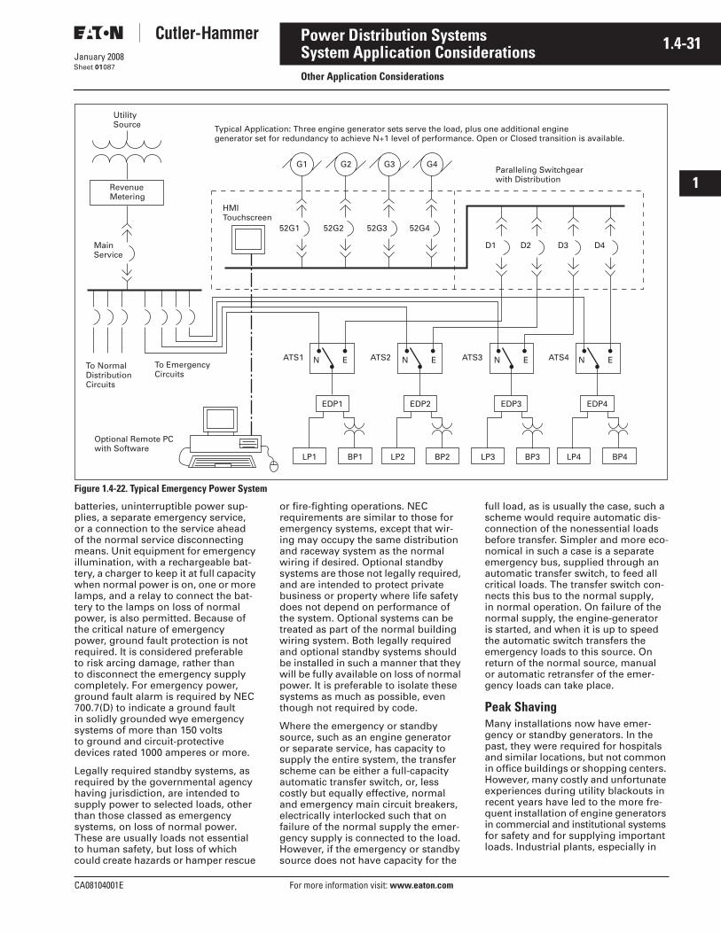
CA08104001E For more information visit: www.eaton.com
1.4-31January 2008
Power Distribution Systems
i
ii
1
2
3
4
5
6
7
8
9
10
11
12
13
14
15
16
17
18
19
20
21
Sheet 01
System Application ConsiderationsOther Application Considerations
087
Figure 1.4-22. Typical Emergency Power System
batteries, uninterruptible power sup-plies, a separate emergency service, or a connection to the service ahead of the normal service disconnecting means. Unit equipment for emergency illumination, with a rechargeable bat-tery, a charger to keep it at full capacity when normal power is on, one or more lamps, and a relay to connect the bat-tery to the lamps on loss of normal power, is also permitted. Because of the critical nature of emergency power, ground fault protection is not required. It is considered preferable to risk arcing damage, rather than to disconnect the emergency supply completely. For emergency power, ground fault alarm is required by NEC 700.7(D) to indicate a ground fault in solidly grounded wye emergency systems of more than 150 volts to ground and circuit-protective devices rated 1000 amperes or more.
Legally required standby systems, as required by the governmental agency having jurisdiction, are intended to supply power to selected loads, other than those classed as emergency systems, on loss of normal power. These are usually loads not essential to human safety, but loss of which could create hazards or hamper rescue
or fire-fighting operations. NEC requirements are similar to those for emergency systems, except that wir-ing may occupy the same distribution and raceway system as the normal wiring if desired. Optional standby systems are those not legally required, and are intended to protect private business or property where life safety does not depend on performance of the system. Optional systems can be treated as part of the normal building wiring system. Both legally required and optional standby systems should be installed in such a manner that they will be fully available on loss of normal power. It is preferable to isolate these systems as much as possible, even though not required by code.
Where the emergency or standby source, such as an engine generator or separate service, has capacity to supply the entire system, the transfer scheme can be either a full-capacity automatic transfer switch, or, less costly but equally effective, normal and emergency main circuit breakers, electrically interlocked such that on failure of the normal supply the emer-gency supply is connected to the load. However, if the emergency or standby source does not have capacity for the
full load, as is usually the case, such a scheme would require automatic dis-connection of the nonessential loads before transfer. Simpler and more eco-nomical in such a case is a separate emergency bus, supplied through an automatic transfer switch, to feed all critical loads. The transfer switch con-nects this bus to the normal supply, in normal operation. On failure of the normal supply, the engine-generator is started, and when it is up to speed the automatic switch transfers the emergency loads to this source. On return of the normal source, manual or automatic retransfer of the emer-gency loads can take place.
Peak ShavingMany installations now have emer-gency or standby generators. In the past, they were required for hospitals and similar locations, but not common in office buildings or shopping centers. However, many costly and unfortunate experiences during utility blackouts in recent years have led to the more fre-quent installation of engine generators in commercial and institutional systems for safety and for supplying important loads. Industrial plants, especially in
To NormalDistributionCircuits
Optional Remote PCwith Software
N
LP1
ATS4
BP1 LP2 BP2 LP3 BP3 LP4 BP4
EDP1 EDP2 EDP3 EDP4
ATS3ATS2ATS1 E N E N E N ETo EmergencyCircuits
D1 D2 D3 D4
52G1 52G2 52G3 52G4
G1 G2 G3 G4
MainService
HMITouchscreen
RevenueMetering
UtilitySource
Paralleling Switchgearwith Distribution
Typical Application: Three engine generator sets serve the load, plus one additional enginegenerator set for redundancy to achieve N+1 level of performance. Open or Closed transition is available.
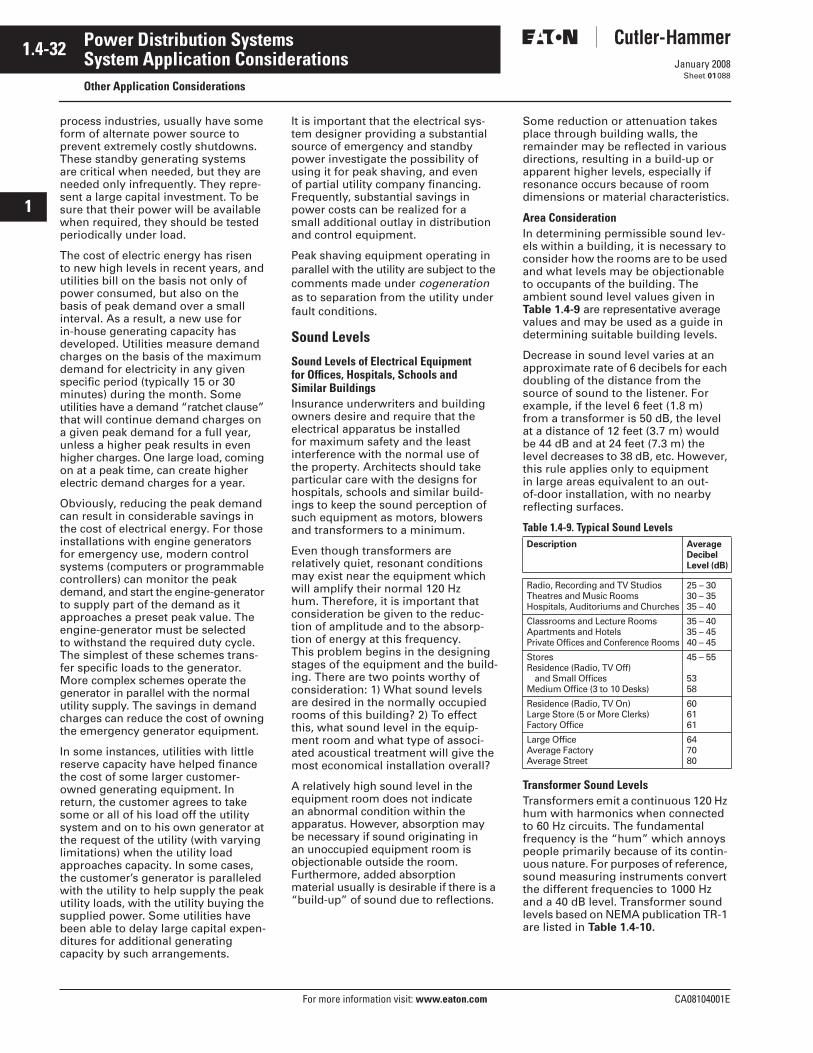
1.4-32
For more information visit: www.eaton.com CA08104001E
January 2008
Power Distribution Systems
i
ii
1
2
3
4
5
6
7
8
9
10
11
12
13
14
15
16
17
18
19
20
21
Sheet 01
System Application ConsiderationsOther Application Considerations
088
process industries, usually have some form of alternate power source to prevent extremely costly shutdowns. These standby generating systems are critical when needed, but they are needed only infrequently. They repre-sent a large capital investment. To be sure that their power will be available when required, they should be tested periodically under load.
The cost of electric energy has risen to new high levels in recent years, and utilities bill on the basis not only of power consumed, but also on the basis of peak demand over a small interval. As a result, a new use for in-house generating capacity has developed. Utilities measure demand charges on the basis of the maximum demand for electricity in any given specific period (typically 15 or 30 minutes) during the month. Some utilities have a demand “ratchet clause” that will continue demand charges on a given peak demand for a full year, unless a higher peak results in even higher charges. One large load, coming on at a peak time, can create higher electric demand charges for a year.
Obviously, reducing the peak demand can result in considerable savings in the cost of electrical energy. For those installations with engine generators for emergency use, modern control systems (computers or programmable controllers) can monitor the peak demand, and start the engine-generator to supply part of the demand as it approaches a preset peak value. The engine-generator must be selected to withstand the required duty cycle. The simplest of these schemes trans-fer specific loads to the generator. More complex schemes operate the generator in parallel with the normal utility supply. The savings in demand charges can reduce the cost of owning the emergency generator equipment.
In some instances, utilities with little reserve capacity have helped finance the cost of some larger customer-owned generating equipment. In return, the customer agrees to take some or all of his load off the utility system and on to his own generator at the request of the utility (with varying limitations) when the utility load approaches capacity. In some cases, the customer’s generator is paralleled with the utility to help supply the peak utility loads, with the utility buying the supplied power. Some utilities have been able to delay large capital expen-ditures for additional generating capacity by such arrangements.
It is important that the electrical sys-tem designer providing a substantial source of emergency and standby power investigate the possibility of using it for peak shaving, and even of partial utility company financing. Frequently, substantial savings in power costs can be realized for a small additional outlay in distribution and control equipment.
Peak shaving equipment operating in parallel with the utility are subject to the comments made under cogeneration as to separation from the utility under fault conditions.
Sound Levels
Sound Levels of Electrical Equipment for Offices, Hospitals, Schools and Similar BuildingsInsurance underwriters and building owners desire and require that the electrical apparatus be installed for maximum safety and the least interference with the normal use of the property. Architects should take particular care with the designs for hospitals, schools and similar build-ings to keep the sound perception of such equipment as motors, blowers and transformers to a minimum.
Even though transformers are relatively quiet, resonant conditions may exist near the equipment which will amplify their normal 120 Hz hum. Therefore, it is important that consideration be given to the reduc-tion of amplitude and to the absorp-tion of energy at this frequency. This problem begins in the designing stages of the equipment and the build-ing. There are two points worthy of consideration: 1) What sound levels are desired in the normally occupied rooms of this building? 2) To effect this, what sound level in the equip-ment room and what type of associ-ated acoustical treatment will give the most economical installation overall?
A relatively high sound level in the equipment room does not indicate an abnormal condition within the apparatus. However, absorption may be necessary if sound originating in an unoccupied equipment room is objectionable outside the room. Furthermore, added absorption material usually is desirable if there is a “build-up” of sound due to reflections.
Some reduction or attenuation takes place through building walls, the remainder may be reflected in various directions, resulting in a build-up or apparent higher levels, especially if resonance occurs because of room dimensions or material characteristics.
Area ConsiderationIn determining permissible sound lev-els within a building, it is necessary to consider how the rooms are to be used and what levels may be objectionable to occupants of the building. The ambient sound level values given in Table 1.4-9 are representative average values and may be used as a guide in determining suitable building levels.
Decrease in sound level varies at an approximate rate of 6 decibels for each doubling of the distance from the source of sound to the listener. For example, if the level 6 feet (1.8 m) from a transformer is 50 dB, the level at a distance of 12 feet (3.7 m) would be 44 dB and at 24 feet (7.3 m) the level decreases to 38 dB, etc. However, this rule applies only to equipment in large areas equivalent to an out-of-door installation, with no nearby reflecting surfaces.
Table 1.4-9. Typical Sound Levels
Transformer Sound LevelsTransformers emit a continuous 120 Hz hum with harmonics when connected to 60 Hz circuits. The fundamental frequency is the “hum” which annoys people primarily because of its contin-uous nature. For purposes of reference, sound measuring instruments convert the different frequencies to 1000 Hz and a 40 dB level. Transformer sound levels based on NEMA publication TR-1 are listed in Table 1.4-10.
Description AverageDecibelLevel (dB)
Radio, Recording and TV StudiosTheatres and Music RoomsHospitals, Auditoriums and Churches
25 – 3030 – 3535 – 40
Classrooms and Lecture RoomsApartments and HotelsPrivate Offices and Conference Rooms
35 – 4035 – 4540 – 45
StoresResidence (Radio, TV Off)
and Small OfficesMedium Office (3 to 10 Desks)
45 – 55
5358
Residence (Radio, TV On)Large Store (5 or More Clerks)Factory Office
606161
Large OfficeAverage FactoryAverage Street
647080
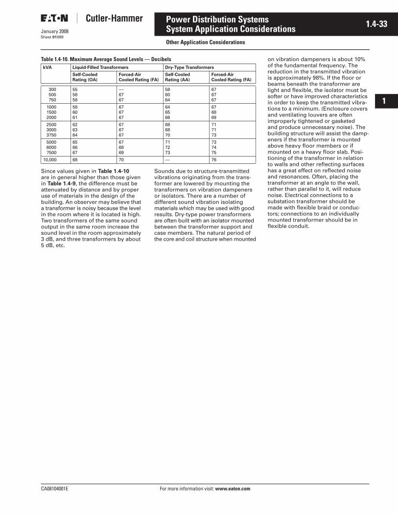
CA08104001E For more information visit: www.eaton.com
1.4-33January 2008
Power Distribution Systems
i
ii
1
2
3
4
5
6
7
8
9
10
11
12
13
14
15
16
17
18
19
20
21
Sheet 01
System Application ConsiderationsOther Application Considerations
089
Table 1.4-10. Maximum Average Sound Levels — Decibels
Since values given in Table 1.4-10 are in general higher than those given in Table 1.4-9, the difference must be attenuated by distance and by proper use of materials in the design of the building. An observer may believe that a transformer is noisy because the level in the room where it is located is high. Two transformers of the same sound output in the same room increase the sound level in the room approximately 3 dB, and three transformers by about 5 dB, etc.
Sounds due to structure-transmitted vibrations originating from the trans-former are lowered by mounting the transformers on vibration dampeners or isolators. There are a number of different sound vibration isolating materials which may be used with good results. Dry-type power transformers are often built with an isolator mounted between the transformer support and case members. The natural period of the core and coil structure when mounted
kVA Liquid-Filled Transformers Dry-Type Transformers
Self-CooledRating (OA)
Forced-AirCooled Rating (FA)
Self-CooledRating (AA)
Forced-AirCooled Rating (FA)
300 500 750
555658
—6767
586064
676767
1000 1500 2000
586061
676767
646566
676869
2500 3000 3750
626364
676767
686870
717173
5000 6000 7500
656667
676869
717273
737475
10,000 68 70 — 76
on vibration dampeners is about 10% of the fundamental frequency. The reduction in the transmitted vibration is approximately 98%. If the floor or beams beneath the transformer are light and flexible, the isolator must be softer or have improved characteristics in order to keep the transmitted vibra-tions to a minimum. (Enclosure covers and ventilating louvers are often improperly tightened or gasketed and produce unnecessary noise). The building structure will assist the damp-eners if the transformer is mounted above heavy floor members or if mounted on a heavy floor slab. Posi-tioning of the transformer in relation to walls and other reflecting surfaces has a great effect on reflected noise and resonances. Often, placing the transformer at an angle to the wall, rather than parallel to it, will reduce noise. Electrical connections to a substation transformer should be made with flexible braid or conduc-tors; connections to an individually mounted transformer should be in flexible conduit.

1.4-34
For more information visit: www.eaton.com CA08104001E
January 2008
Power Distribution Systems
i
ii
1
2
3
4
5
6
7
8
9
10
11
12
13
14
15
16
17
18
19
20
21
Sheet 01090
This page intentionally left blank.
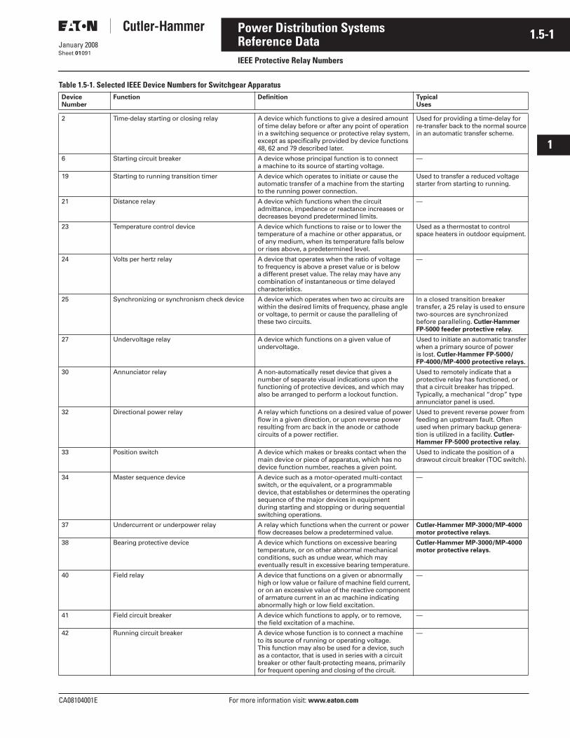
CA08104001E For more information visit: www.eaton.com
1.5-1January 2008
Power Distribution Systems
i
ii
1
2
3
4
5
6
7
8
9
10
11
12
13
14
15
16
17
18
19
20
21
Sheet 01
Reference DataIEEE Protective Relay Numbers
091
Table 1.5-1. Selected IEEE Device Numbers for Switchgear ApparatusDevice Number
Function Definition Typical Uses
2 Time-delay starting or closing relay A device which functions to give a desired amount of time delay before or after any point of operation in a switching sequence or protective relay system, except as specifically provided by device functions 48, 62 and 79 described later.
Used for providing a time-delay forre-transfer back to the normal sourcein an automatic transfer scheme.
6 Starting circuit breaker A device whose principal function is to connect a machine to its source of starting voltage.
—
19 Starting to running transition timer A device which operates to initiate or cause theautomatic transfer of a machine from the starting to the running power connection.
Used to transfer a reduced voltagestarter from starting to running.
21 Distance relay A device which functions when the circuit admittance, impedance or reactance increases ordecreases beyond predetermined limits.
—
23 Temperature control device A device which functions to raise or to lower the temperature of a machine or other apparatus, orof any medium, when its temperature falls below or rises above, a predetermined level.
Used as a thermostat to controlspace heaters in outdoor equipment.
24 Volts per hertz relay A device that operates when the ratio of voltage to frequency is above a preset value or is below a different preset value. The relay may have any combination of instantaneous or time delayedcharacteristics.
—
25 Synchronizing or synchronism check device A device which operates when two ac circuits arewithin the desired limits of frequency, phase angleor voltage, to permit or cause the paralleling ofthese two circuits.
In a closed transition breaker transfer, a 25 relay is used to ensure two-sources are synchronized before paralleling. Cutler-Hammer FP-5000 feeder protective relay.
27 Undervoltage relay A device which functions on a given value of undervoltage.
Used to initiate an automatic transferwhen a primary source of power is lost. Cutler-Hammer FP-5000/FP-4000/MP-4000 protective relays.
30 Annunciator relay A non-automatically reset device that gives a number of separate visual indications upon the functioning of protective devices, and which mayalso be arranged to perform a lockout function.
Used to remotely indicate that a protective relay has functioned, or that a circuit breaker has tripped. Typically, a mechanical “drop” typeannunciator panel is used.
32 Directional power relay A relay which functions on a desired value of powerflow in a given direction, or upon reverse power resulting from arc back in the anode or cathode circuits of a power rectifier.
Used to prevent reverse power from feeding an upstream fault. Often used when primary backup genera-tion is utilized in a facility. Cutler-Hammer FP-5000 protective relay.
33 Position switch A device which makes or breaks contact when themain device or piece of apparatus, which has no device function number, reaches a given point.
Used to indicate the position of a drawout circuit breaker (TOC switch).
34 Master sequence device A device such as a motor-operated multi-contact switch, or the equivalent, or a programmable device, that establishes or determines the operating sequence of the major devices in equipment during starting and stopping or during sequential switching operations.
—
37 Undercurrent or underpower relay A relay which functions when the current or powerflow decreases below a predetermined value.
Cutler-Hammer MP-3000/MP-4000 motor protective relays.
38 Bearing protective device A device which functions on excessive bearingtemperature, or on other abnormal mechanical conditions, such as undue wear, which may eventually result in excessive bearing temperature.
Cutler-Hammer MP-3000/MP-4000 motor protective relays.
40 Field relay A device that functions on a given or abnormally high or low value or failure of machine field current, or on an excessive value of the reactive component of armature current in an ac machine indicating abnormally high or low field excitation.
—
41 Field circuit breaker A device which functions to apply, or to remove,the field excitation of a machine.
—
42 Running circuit breaker A device whose function is to connect a machine to its source of running or operating voltage. This function may also be used for a device, such as a contactor, that is used in series with a circuit breaker or other fault-protecting means, primarily for frequent opening and closing of the circuit.
—
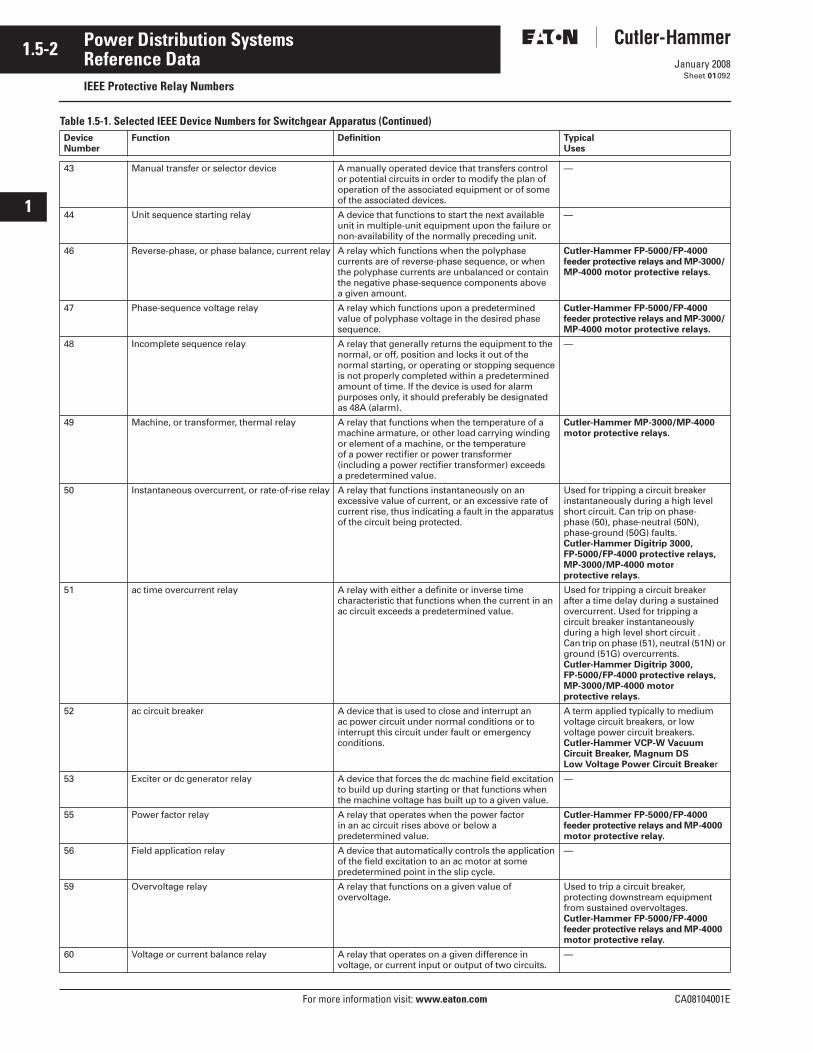
1.5-2
For more information visit: www.eaton.com CA08104001E
January 2008
Power Distribution Systems
i
ii
1
2
3
4
5
6
7
8
9
10
11
12
13
14
15
16
17
18
19
20
21
Sheet 01
Reference DataIEEE Protective Relay Numbers
092
Table 1.5-1. Selected IEEE Device Numbers for Switchgear Apparatus (Continued)Device Number
Function Definition Typical Uses
43 Manual transfer or selector device A manually operated device that transfers control or potential circuits in order to modify the plan of operation of the associated equipment or of some of the associated devices.
—
44 Unit sequence starting relay A device that functions to start the next available unit in multiple-unit equipment upon the failure or non-availability of the normally preceding unit.
—
46 Reverse-phase, or phase balance, current relay A relay which functions when the polyphasecurrents are of reverse-phase sequence, or when the polyphase currents are unbalanced or containthe negative phase-sequence components above a given amount.
Cutler-Hammer FP-5000/FP-4000 feeder protective relays and MP-3000/MP-4000 motor protective relays.
47 Phase-sequence voltage relay A relay which functions upon a predetermined value of polyphase voltage in the desired phase sequence.
Cutler-Hammer FP-5000/FP-4000 feeder protective relays and MP-3000/MP-4000 motor protective relays.
48 Incomplete sequence relay A relay that generally returns the equipment to thenormal, or off, position and locks it out of the normal starting, or operating or stopping sequenceis not properly completed within a predeterminedamount of time. If the device is used for alarm purposes only, it should preferably be designatedas 48A (alarm).
—
49 Machine, or transformer, thermal relay A relay that functions when the temperature of a machine armature, or other load carrying windingor element of a machine, or the temperature of a power rectifier or power transformer (including a power rectifier transformer) exceeds a predetermined value.
Cutler-Hammer MP-3000/MP-4000 motor protective relays.
50 Instantaneous overcurrent, or rate-of-rise relay A relay that functions instantaneously on an excessive value of current, or an excessive rate of current rise, thus indicating a fault in the apparatus of the circuit being protected.
Used for tripping a circuit breakerinstantaneously during a high levelshort circuit. Can trip on phase-phase (50), phase-neutral (50N), phase-ground (50G) faults. Cutler-Hammer Digitrip 3000, FP-5000/FP-4000 protective relays, MP-3000/MP-4000 motor protective relays.
51 ac time overcurrent relay A relay with either a definite or inverse time characteristic that functions when the current in anac circuit exceeds a predetermined value.
Used for tripping a circuit breaker after a time delay during a sustainedovercurrent. Used for tripping a circuit breaker instantaneously during a high level short circuit . Can trip on phase (51), neutral (51N) or ground (51G) overcurrents. Cutler-Hammer Digitrip 3000, FP-5000/FP-4000 protective relays, MP-3000/MP-4000 motor protective relays.
52 ac circuit breaker A device that is used to close and interrupt an ac power circuit under normal conditions or to interrupt this circuit under fault or emergency conditions.
A term applied typically to mediumvoltage circuit breakers, or low voltage power circuit breakers.Cutler-Hammer VCP-W Vacuum Circuit Breaker, Magnum DS Low Voltage Power Circuit Breaker
53 Exciter or dc generator relay A device that forces the dc machine field excitation to build up during starting or that functions when the machine voltage has built up to a given value.
—
55 Power factor relay A relay that operates when the power factor in an ac circuit rises above or below a predetermined value.
Cutler-Hammer FP-5000/FP-4000 feeder protective relays and MP-4000 motor protective relay.
56 Field application relay A device that automatically controls the application of the field excitation to an ac motor at some predetermined point in the slip cycle.
—
59 Overvoltage relay A relay that functions on a given value of overvoltage.
Used to trip a circuit breaker, protecting downstream equipment from sustained overvoltages. Cutler-Hammer FP-5000/FP-4000 feeder protective relays and MP-4000 motor protective relay.
60 Voltage or current balance relay A relay that operates on a given difference in voltage, or current input or output of two circuits.
—
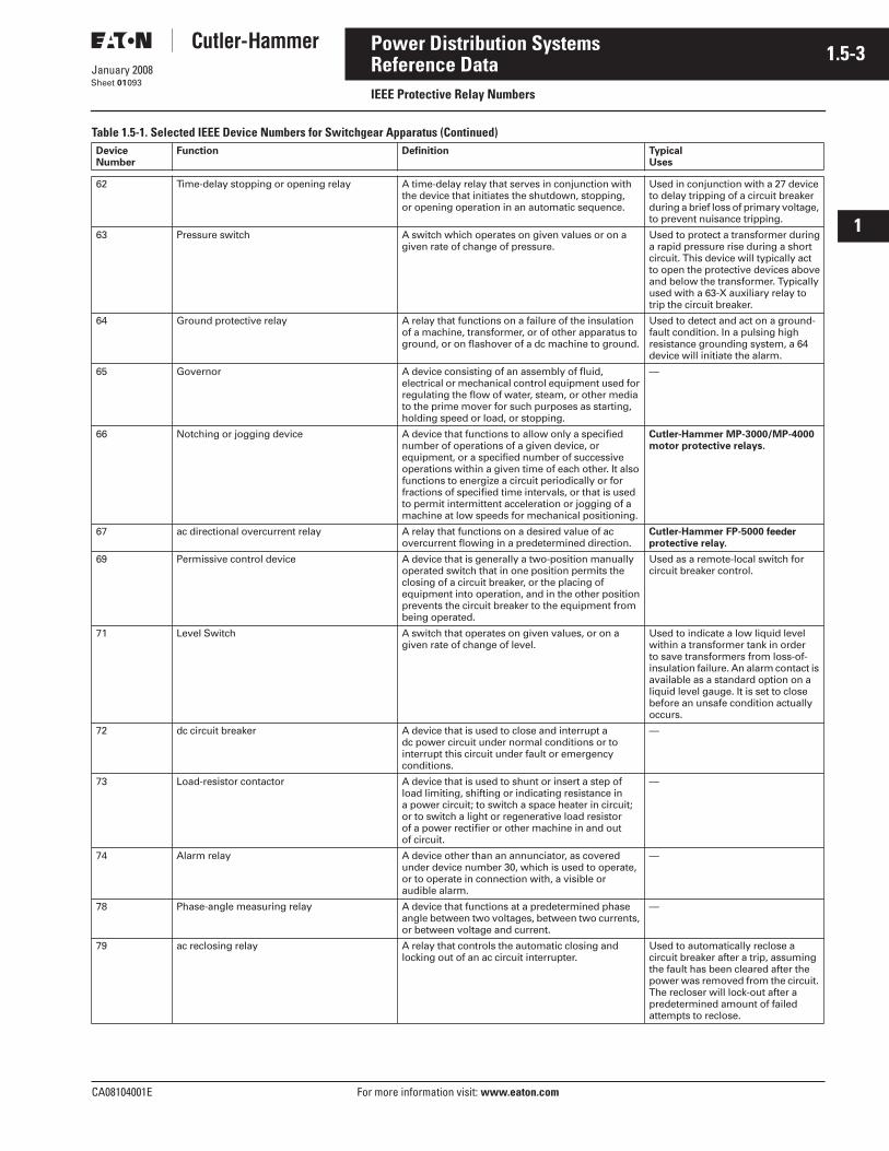
CA08104001E For more information visit: www.eaton.com
1.5-3January 2008
Power Distribution Systems
i
ii
1
2
3
4
5
6
7
8
9
10
11
12
13
14
15
16
17
18
19
20
21
Sheet 01
Reference DataIEEE Protective Relay Numbers
093
Table 1.5-1. Selected IEEE Device Numbers for Switchgear Apparatus (Continued)Device Number
Function Definition Typical Uses
62 Time-delay stopping or opening relay A time-delay relay that serves in conjunction with the device that initiates the shutdown, stopping, or opening operation in an automatic sequence.
Used in conjunction with a 27 device to delay tripping of a circuit breakerduring a brief loss of primary voltage, to prevent nuisance tripping.
63 Pressure switch A switch which operates on given values or on a given rate of change of pressure.
Used to protect a transformer duringa rapid pressure rise during a shortcircuit. This device will typically act to open the protective devices aboveand below the transformer. Typicallyused with a 63-X auxiliary relay totrip the circuit breaker.
64 Ground protective relay A relay that functions on a failure of the insulationof a machine, transformer, or of other apparatus to ground, or on flashover of a dc machine to ground.
Used to detect and act on a ground-fault condition. In a pulsing high resistance grounding system, a 64 device will initiate the alarm.
65 Governor A device consisting of an assembly of fluid, electrical or mechanical control equipment used for regulating the flow of water, steam, or other media to the prime mover for such purposes as starting, holding speed or load, or stopping.
—
66 Notching or jogging device A device that functions to allow only a specified number of operations of a given device, orequipment, or a specified number of successive operations within a given time of each other. It also functions to energize a circuit periodically or forfractions of specified time intervals, or that is usedto permit intermittent acceleration or jogging of a machine at low speeds for mechanical positioning.
Cutler-Hammer MP-3000/MP-4000 motor protective relays.
67 ac directional overcurrent relay A relay that functions on a desired value of acovercurrent flowing in a predetermined direction.
Cutler-Hammer FP-5000 feederprotective relay.
69 Permissive control device A device that is generally a two-position manuallyoperated switch that in one position permits the closing of a circuit breaker, or the placing of equipment into operation, and in the other positionprevents the circuit breaker to the equipment from being operated.
Used as a remote-local switch for circuit breaker control.
71 Level Switch A switch that operates on given values, or on a given rate of change of level.
Used to indicate a low liquid level within a transformer tank in order to save transformers from loss-of-insulation failure. An alarm contact is available as a standard option on a liquid level gauge. It is set to close before an unsafe condition actually occurs.
72 dc circuit breaker A device that is used to close and interrupt a dc power circuit under normal conditions or to interrupt this circuit under fault or emergencyconditions.
—
73 Load-resistor contactor A device that is used to shunt or insert a step of load limiting, shifting or indicating resistance in a power circuit; to switch a space heater in circuit; or to switch a light or regenerative load resistor of a power rectifier or other machine in and out of circuit.
—
74 Alarm relay A device other than an annunciator, as covered under device number 30, which is used to operate, or to operate in connection with, a visible or audible alarm.
—
78 Phase-angle measuring relay A device that functions at a predetermined phase angle between two voltages, between two currents, or between voltage and current.
—
79 ac reclosing relay A relay that controls the automatic closing and locking out of an ac circuit interrupter.
Used to automatically reclose a circuit breaker after a trip, assumingthe fault has been cleared after the power was removed from the circuit. The recloser will lock-out after a predetermined amount of failedattempts to reclose.
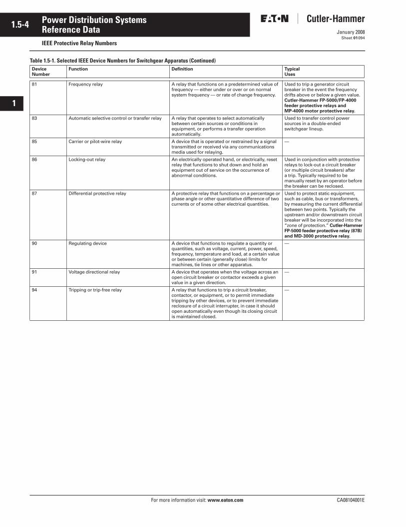
1.5-4
For more information visit: www.eaton.com CA08104001E
January 2008
Power Distribution Systems
i
ii
1
2
3
4
5
6
7
8
9
10
11
12
13
14
15
16
17
18
19
20
21
Sheet 01
Reference DataIEEE Protective Relay Numbers
094
Table 1.5-1. Selected IEEE Device Numbers for Switchgear Apparatus (Continued)Device Number
Function Definition Typical Uses
81 Frequency relay A relay that functions on a predetermined value of frequency — either under or over or on normal system frequency — or rate of change frequency.
Used to trip a generator circuit breaker in the event the frequency drifts above or below a given value.Cutler-Hammer FP-5000/FP-4000 feeder protective relays and MP-4000 motor protective relay.
83 Automatic selective control or transfer relay A relay that operates to select automatically between certain sources or conditions in equipment, or performs a transfer operation automatically.
Used to transfer control power sources in a double-ended switchgear lineup.
85 Carrier or pilot-wire relay A device that is operated or restrained by a signal transmitted or received via any communications media used for relaying.
—
86 Locking-out relay An electrically operated hand, or electrically, resetrelay that functions to shut down and hold an equipment out of service on the occurrence of abnormal conditions.
Used in conjunction with protectiverelays to lock-out a circuit breaker(or multiple circuit breakers) after a trip. Typically required to be manually reset by an operator before the breaker can be reclosed.
87 Differential protective relay A protective relay that functions on a percentage or phase angle or other quantitative difference of twocurrents or of some other electrical quantities.
Used to protect static equipment,such as cable, bus or transformers,by measuring the current differentialbetween two points. Typically the upstream and/or downstream circuitbreaker will be incorporated into the“zone of protection.” Cutler-HammerFP-5000 feeder protective relay (87B) and MD-3000 protective relay.
90 Regulating device A device that functions to regulate a quantity or quantities, such as voltage, current, power, speed, frequency, temperature and load, at a certain value or between certain (generally close) limits for machines, tie lines or other apparatus.
—
91 Voltage directional relay A device that operates when the voltage across an open circuit breaker or contactor exceeds a given value in a given direction.
—
94 Tripping or trip-free relay A relay that functions to trip a circuit breaker, contactor, or equipment, or to permit immediate tripping by other devices, or to prevent immediate reclosure of a circuit interrupter, in case it should open automatically even though its closing circuitis maintained closed.
—
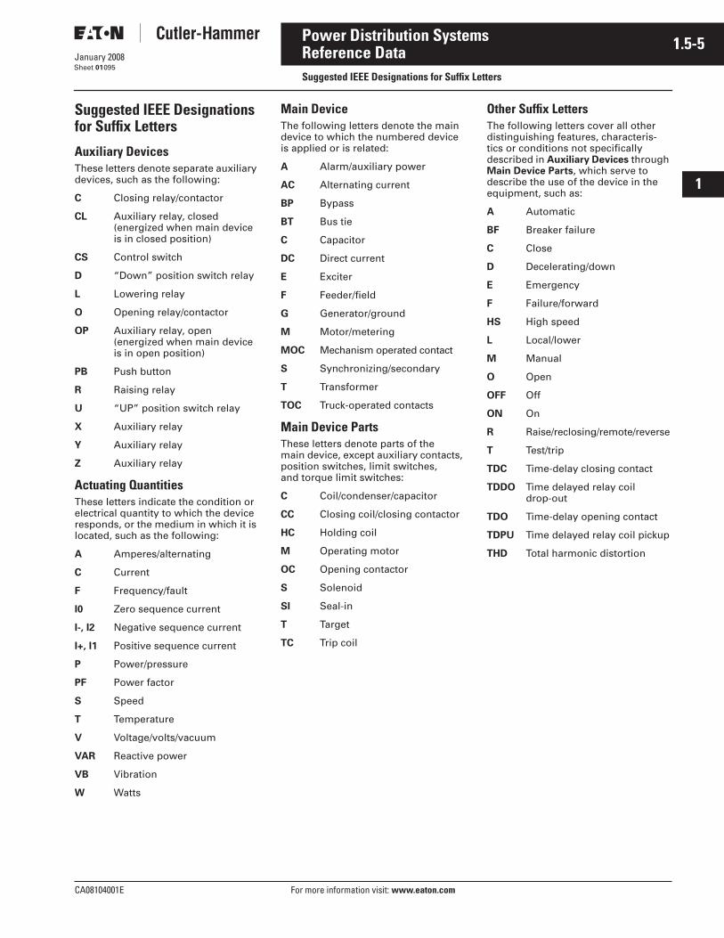
CA08104001E For more information visit: www.eaton.com
1.5-5January 2008
Power Distribution Systems
i
ii
1
2
3
4
5
6
7
8
9
10
11
12
13
14
15
16
17
18
19
20
21
Sheet 01
Reference DataSuggested IEEE Designations for Suffix Letters
095
Suggested IEEE Designations for Suffix Letters
Auxiliary DevicesThese letters denote separate auxiliary devices, such as the following:
C Closing relay/contactor
CL Auxiliary relay, closed (energized when main device is in closed position)
CS Control switch
D “Down” position switch relay
L Lowering relay
O Opening relay/contactor
OP Auxiliary relay, open (energized when main device is in open position)
PB Push button
R Raising relay
U “UP” position switch relay
X Auxiliary relay
Y Auxiliary relay
Z Auxiliary relay
Actuating QuantitiesThese letters indicate the condition or electrical quantity to which the device responds, or the medium in which it is located, such as the following:
A Amperes/alternating
C Current
F Frequency/fault
I0 Zero sequence current
I-, I2 Negative sequence current
I+, I1 Positive sequence current
P Power/pressure
PF Power factor
S Speed
T Temperature
V Voltage/volts/vacuum
VAR Reactive power
VB Vibration
W Watts
Main DeviceThe following letters denote the main device to which the numbered device is applied or is related:
A Alarm/auxiliary power
AC Alternating current
BP Bypass
BT Bus tie
C Capacitor
DC Direct current
E Exciter
F Feeder/field
G Generator/ground
M Motor/metering
MOC Mechanism operated contact
S Synchronizing/secondary
T Transformer
TOC Truck-operated contacts
Main Device PartsThese letters denote parts of the main device, except auxiliary contacts, position switches, limit switches, and torque limit switches:
C Coil/condenser/capacitor
CC Closing coil/closing contactor
HC Holding coil
M Operating motor
OC Opening contactor
S Solenoid
SI Seal-in
T Target
TC Trip coil
Other Suffix LettersThe following letters cover all other distinguishing features, characteris-tics or conditions not specifically described in Auxiliary Devices through Main Device Parts, which serve to describe the use of the device in the equipment, such as:
A Automatic
BF Breaker failure
C Close
D Decelerating/down
E Emergency
F Failure/forward
HS High speed
L Local/lower
M Manual
O Open
OFF Off
ON On
R Raise/reclosing/remote/reverse
T Test/trip
TDC Time-delay closing contact
TDDO Time delayed relay coil drop-out
TDO Time-delay opening contact
TDPU Time delayed relay coil pickup
THD Total harmonic distortion
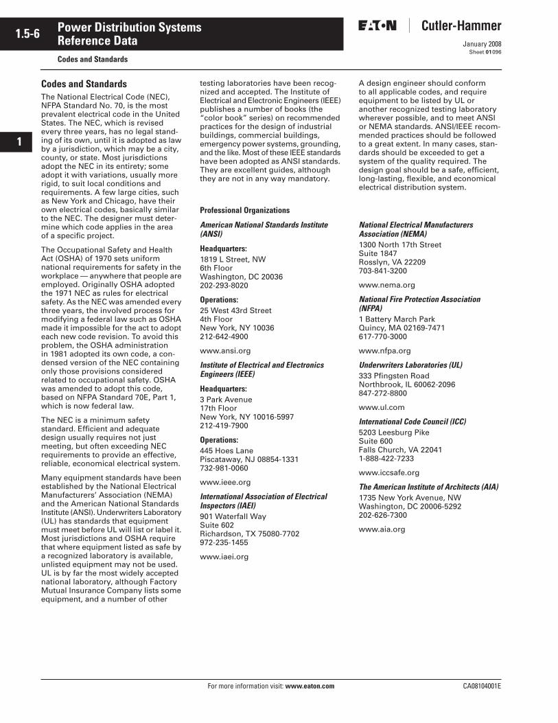
1.5-6
For more information visit: www.eaton.com CA08104001E
January 2008
Power Distribution Systems
i
ii
1
2
3
4
5
6
7
8
9
10
11
12
13
14
15
16
17
18
19
20
21
Sheet 01
Reference DataCodes and Standards
096
Codes and StandardsThe National Electrical Code (NEC), NFPA Standard No. 70, is the most prevalent electrical code in the United States. The NEC, which is revised every three years, has no legal stand-ing of its own, until it is adopted as law by a jurisdiction, which may be a city, county, or state. Most jurisdictions adopt the NEC in its entirety; some adopt it with variations, usually more rigid, to suit local conditions and requirements. A few large cities, such as New York and Chicago, have their own electrical codes, basically similar to the NEC. The designer must deter-mine which code applies in the area of a specific project.
The Occupational Safety and Health Act (OSHA) of 1970 sets uniform national requirements for safety in the workplace — anywhere that people are employed. Originally OSHA adopted the 1971 NEC as rules for electrical safety. As the NEC was amended every three years, the involved process for modifying a federal law such as OSHA made it impossible for the act to adopt each new code revision. To avoid this problem, the OSHA administration in 1981 adopted its own code, a con-densed version of the NEC containing only those provisions considered related to occupational safety. OSHA was amended to adopt this code, based on NFPA Standard 70E, Part 1, which is now federal law.
The NEC is a minimum safety standard. Efficient and adequate design usually requires not just meeting, but often exceeding NEC requirements to provide an effective, reliable, economical electrical system.
Many equipment standards have been established by the National Electrical Manufacturers’ Association (NEMA) and the American National Standards Institute (ANSI). Underwriters Laboratory (UL) has standards that equipment must meet before UL will list or label it. Most jurisdictions and OSHA require that where equipment listed as safe by a recognized laboratory is available, unlisted equipment may not be used. UL is by far the most widely accepted national laboratory, although Factory Mutual Insurance Company lists some equipment, and a number of other
testing laboratories have been recog-nized and accepted. The Institute of Electrical and Electronic Engineers (IEEE) publishes a number of books (the “color book” series) on recommended practices for the design of industrial buildings, commercial buildings, emergency power systems, grounding, and the like. Most of these IEEE standards have been adopted as ANSI standards. They are excellent guides, although they are not in any way mandatory.
A design engineer should conform to all applicable codes, and require equipment to be listed by UL or another recognized testing laboratory wherever possible, and to meet ANSI or NEMA standards. ANSI/IEEE recom-mended practices should be followed to a great extent. In many cases, stan-dards should be exceeded to get a system of the quality required. The design goal should be a safe, efficient, long-lasting, flexible, and economical electrical distribution system.
Professional Organizations
American National Standards Institute(ANSI)
Headquarters:1819 L Street, NW6th FloorWashington, DC 20036202-293-8020
Operations:25 West 43rd Street4th FloorNew York, NY 10036212-642-4900
www.ansi.org
Institute of Electrical and Electronics Engineers (IEEE)
Headquarters:3 Park Avenue17th FloorNew York, NY 10016-5997212-419-7900
Operations:445 Hoes LanePiscataway, NJ 08854-1331732-981-0060
www.ieee.org
International Association of Electrical Inspectors (IAEI)901 Waterfall WaySuite 602Richardson, TX 75080-7702972-235-1455
www.iaei.org
National Electrical Manufacturers Association (NEMA)1300 North 17th StreetSuite 1847Rosslyn, VA 22209703-841-3200
www.nema.org
National Fire Protection Association(NFPA)1 Battery March ParkQuincy, MA 02169-7471617-770-3000
www.nfpa.org
Underwriters Laboratories (UL)333 Pfingsten RoadNorthbrook, IL 60062-2096847-272-8800
www.ul.com
International Code Council (ICC)5203 Leesburg PikeSuite 600Falls Church, VA 220411-888-422-7233
www.iccsafe.org
The American Institute of Architects (AIA)1735 New York Avenue, NWWashington, DC 20006-5292202-626-7300
www.aia.org
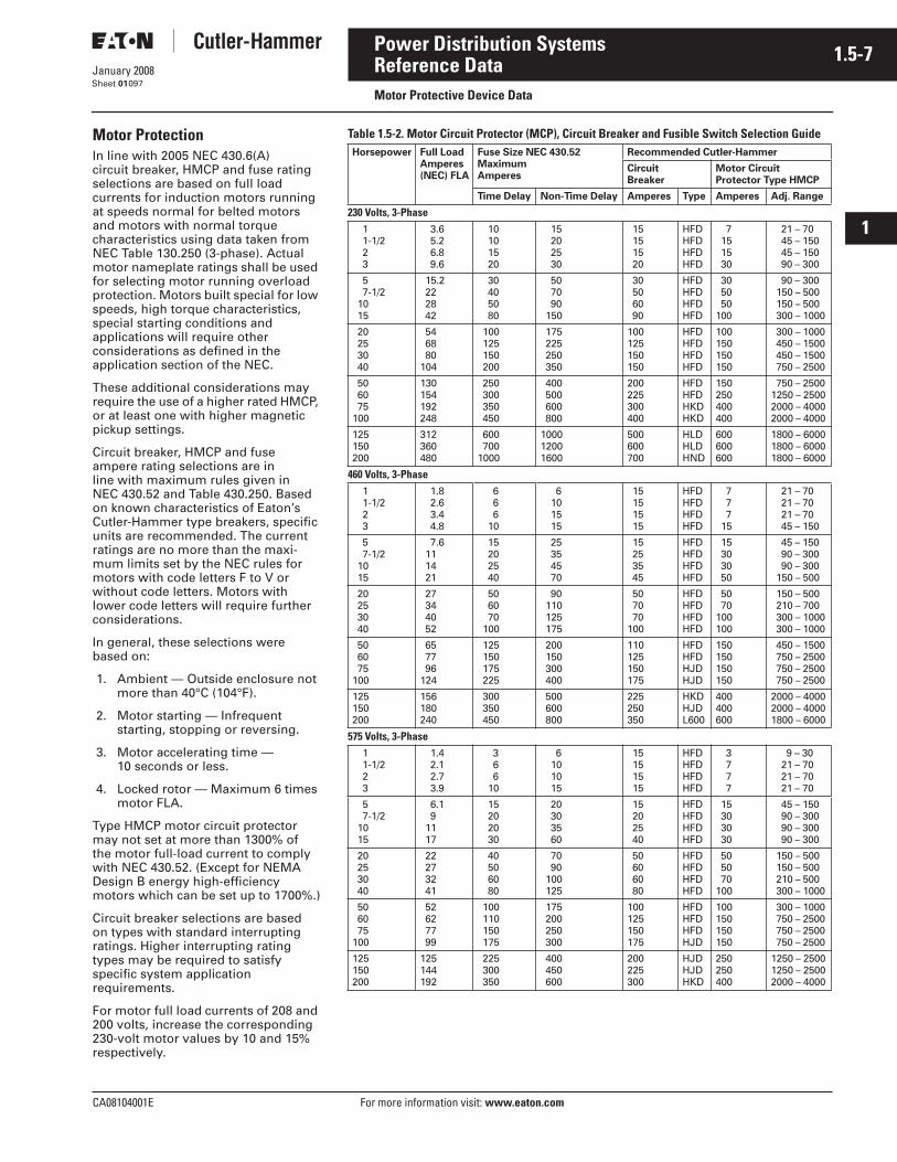
CA08104001E For more information visit: www.eaton.com
1.5-7January 2008
Power Distribution Systems
i
ii
1
2
3
4
5
6
7
8
9
10
11
12
13
14
15
16
17
18
19
20
21
Sheet 01
Reference DataMotor Protective Device Data
097
Motor ProtectionIn line with 2005 NEC 430.6(A) circuit breaker, HMCP and fuse rating selections are based on full load currents for induction motors running at speeds normal for belted motors and motors with normal torque characteristics using data taken from NEC Table 130.250 (3-phase). Actual motor nameplate ratings shall be used for selecting motor running overload protection. Motors built special for low speeds, high torque characteristics, special starting conditions and applications will require other considerations as defined in the application section of the NEC.
These additional considerations may require the use of a higher rated HMCP, or at least one with higher magnetic pickup settings.
Circuit breaker, HMCP and fuse ampere rating selections are in line with maximum rules given in NEC 430.52 and Table 430.250. Based on known characteristics of Eaton’s Cutler-Hammer type breakers, specific units are recommended. The current ratings are no more than the maxi-mum limits set by the NEC rules for motors with code letters F to V or without code letters. Motors with lower code letters will require further considerations.
In general, these selections were based on:
1. Ambient — Outside enclosure not more than 40°C (104°F).
2. Motor starting — Infrequent starting, stopping or reversing.
3. Motor accelerating time — 10 seconds or less.
4. Locked rotor — Maximum 6 times motor FLA.
Type HMCP motor circuit protector may not set at more than 1300% of the motor full-load current to comply with NEC 430.52. (Except for NEMA Design B energy high-efficiency motors which can be set up to 1700%.)
Circuit breaker selections are based on types with standard interrupting ratings. Higher interrupting rating types may be required to satisfy specific system application requirements.
For motor full load currents of 208 and 200 volts, increase the corresponding 230-volt motor values by 10 and 15% respectively.
Table 1.5-2. Motor Circuit Protector (MCP), Circuit Breaker and Fusible Switch Selection GuideHorsepower Full Load
Amperes(NEC) FLA
Fuse Size NEC 430.52Maximum Amperes
Recommended Cutler-Hammer
Circuit Breaker
Motor Circuit Protector Type HMCP
Time Delay Non-Time Delay Amperes Type Amperes Adj. Range
230 Volts, 3-Phase 1 1-1/2 2 3
3.6 5.2 6.8 9.6
10 10 15 20
15 20 25 30
15 15 15 20
HFDHFDHFDHFD
7 15 15 30
21 – 70 45 – 150 45 – 150 90 – 300
5 7-1/2 10 15
15.2 22 28 42
30 40 50 80
50 70 90 150
30 50 60 90
HFDHFDHFDHFD
30 50 50100
90 – 300 150 – 500 150 – 500 300 – 1000
20 25 30 40
54 68 80104
100 125 150 200
175 225 250 350
100125150150
HFDHFDHFDHFD
100150150150
300 – 1000 450 – 1500 450 – 1500 750 – 2500
50 60 75100
130154192248
250 300 350 450
400 500 600 800
200225300400
HFDHFDHKDHKD
150250400400
750 – 25001250 – 25002000 – 40002000 – 4000
125150200
312360480
600 7001000
100012001600
500600700
HLDHLDHND
600600600
1800 – 60001800 – 60001800 – 6000
460 Volts, 3-Phase 1 1-1/2 2 3
1.8 2.6 3.4 4.8
6 6 6 10
6 10 15 15
15 15 15 15
HFDHFDHFDHFD
7 7 7 15
21 – 70 21 – 70 21 – 70 45 – 150
5 7-1/2 10 15
7.6 11 14 21
15 20 25 40
25 35 45 70
15 25 35 45
HFDHFDHFDHFD
15 30 30 50
45 – 150 90 – 300 90 – 300 150 – 500
20 25 30 40
27 34 40 52
50 60 70 100
90 110 125 175
50 70 70100
HFDHFDHFDHFD
50 70100100
150 – 500 210 – 700 300 – 1000 300 – 1000
50 60 75100
65 77 96124
125 150 175 225
200 150 300 400
110125150175
HFDHFDHJDHJD
150150150150
450 – 1500 750 – 2500 750 – 2500 750 – 2500
125150200
156180240
300 350 450
500 600 800
225250350
HKDHJDL600
400400600
2000 – 40002000 – 40001800 – 6000
575 Volts, 3-Phase 1 1-1/2 2 3
1.4 2.1 2.7 3.9
3 6 6 10
6 10 10 15
15 15 15 15
HFDHFDHFDHFD
3 7 7 7
9 – 30 21 – 70 21 – 70 21 – 70
5 7-1/2 10 15
6.1 9 11 17
15 20 20 30
20 30 35 60
15 20 25 40
HFDHFDHFDHFD
15 30 30 30
45 – 150 90 – 300 90 – 300 90 – 300
20 25 30 40
22 27 32 41
40 50 60 80
70 90 100 125
50 60 60 80
HFDHFDHFDHFD
50 50 70100
150 – 500 150 – 500 210 – 500 300 – 1000
50 60 75100
52 62 77 99
100 110 150 175
175 200 250 300
100125150175
HFDHFDHFDHJD
100150150150
300 – 1000 750 – 2500 750 – 2500 750 – 2500
125150200
125144192
225 300 350
400 450 600
200225300
HJDHJDHKD
250250400
1250 – 25001250 – 25002000 – 4000
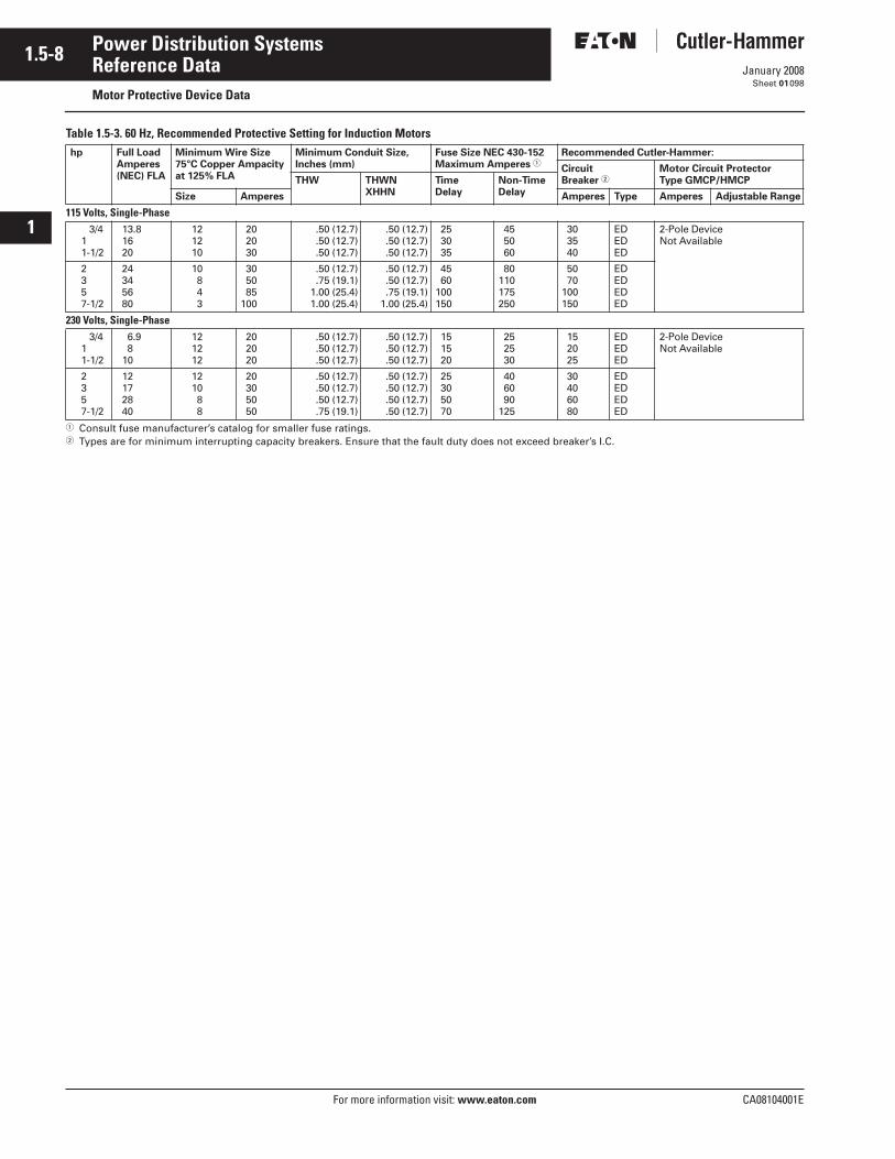
1.5-8
For more information visit: www.eaton.com CA08104001E
January 2008
Power Distribution Systems
i
ii
1
2
3
4
5
6
7
8
9
10
11
12
13
14
15
16
17
18
19
20
21
Sheet 01
Reference DataMotor Protective Device Data
098
Table 1.5-3. 60 Hz, Recommended Protective Setting for Induction Motors
� Consult fuse manufacturer’s catalog for smaller fuse ratings.� Types are for minimum interrupting capacity breakers. Ensure that the fault duty does not exceed breaker’s I.C.
hp Full LoadAmperes(NEC) FLA
Minimum Wire Size75°C Copper Ampacityat 125% FLA
Minimum Conduit Size,Inches (mm)
Fuse Size NEC 430-152Maximum Amperes �
Recommended Cutler-Hammer:
CircuitBreaker �
Motor Circuit Protector Type GMCP/HMCPTHW THWN
XHHNTimeDelay
Non-TimeDelaySize Amperes Amperes Type Amperes Adjustable Range
115 Volts, Single-Phase 3/4 1 1-1/2
13.8 16 20
12 12 10
20 20 30
.50 (12.7) .50 (12.7) .50 (12.7)
.50 (12.7)
.50 (12.7)
.50 (12.7)
25 30 35
45 50 60
30 35 40
EDEDED
2-Pole DeviceNot Available
2 3 5 7-1/2
24 34 56 80
10 8 4 3
30 50 85100
.50 (12.7) .75 (19.1)1.00 (25.4)1.00 (25.4)
.50 (12.7)
.50 (12.7)
.75 (19.1)1.00 (25.4)
45 60100150
80110175250
50 70100150
EDEDEDED
230 Volts, Single-Phase 3/4 1 1-1/2
6.9 8 10
12 12 12
20 20 20
.50 (12.7) .50 (12.7) .50 (12.7)
.50 (12.7)
.50 (12.7)
.50 (12.7)
15 15 20
25 25 30
15 20 25
EDEDED
2-Pole DeviceNot Available
2 3 5 7-1/2
12 17 28 40
12 10 8 8
20 30 50 50
.50 (12.7) .50 (12.7) .50 (12.7) .75 (19.1)
.50 (12.7)
.50 (12.7)
.50 (12.7)
.50 (12.7)
25 30 50 70
40 60 90125
30 40 60 80
EDEDEDED
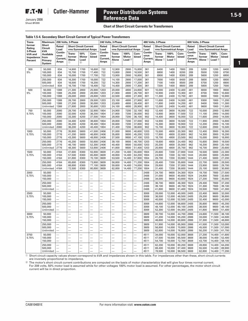
CA08104001E For more information visit: www.eaton.com
1.5-9January 2008
Power Distribution Systems
i
ii
1
2
3
4
5
6
7
8
9
10
11
12
13
14
15
16
17
18
19
20
21
Sheet 01
Reference DataChart of Short Circuit Currents for Transformers
099
Table 1.5-4. Secondary Short Circuit Current of Typical Power Transformers
� Short circuit capacity values shown correspond to kVA and impedances shown in this table. For impedances other than these, short circuit currents are inversely proportional to impedance.
� The motor’s short circuit current contributions are computed on the basis of motor characteristics that will give four times normal current. For 208 volts, 50% motor load is assumed while for other voltages 100% motor load is assumed. For other percentages, the motor short circuit current will be in direct proportion.
Trans-
former
Rating
3-Phase
kVA and
Impedance
Percent
Maximum
Short
Circuit
kVA
Available
from
Primary
System
208 Volts, 3-Phase 240 Volts, 3-Phase 480 Volts, 3-Phase 600 Volts, 3-Phase
Rated
Load
Contin-
uous
Current,
Amps
Short Circuit Current
rms Symmetrical Amps
Rated
Load
Contin-
uous
Current,
Amps
Short Circuit Current
rms Symmetrical Amps
Rated
Load
Contin-
uous
Current,
Amps
Short Circuit Current
rms Symmetrical Amps
Rated
Load
Contin-
uous
Current,
Amps
Short Circuit Current
rms Symmetrical Amps
Trans-
former
Alone �
50%
Motor
Load �
Com-
bined
Trans-
former
Alone �
100%
Motor
Load �
Com-
bined
Trans-
former
Alone �
100%
Motor
Load �
Com-
bined
Trans-
former
Alone �
100%
Motor
Load �
Com-
bined
3005%
50,000100,000150,000
834 834 834
14,90015,70016,000
170017001700
16,60017,40017,700
722 722 722
12,90013,60013,900
2900 2900 2900
15,80016,50016,800
361 361 361
6400 6800 6900
1400 1400 1400
7800 8200 8300
289 289 289
5200 5500 5600
1200 1200 1200
6400 6700 6800
250,000500,000Unlimited
834 834 834
16,30016,50016,700
170017001700
18,00018,20018,400
722 722 722
14,10014,30014,400
2900 2900 2900
17,00017,20017,300
361 361 361
7000 7100 7200
1400 1400 1400
8400 8500 8600
289 289 289
5600 5700 5800
1200 1200 1200
6800 6900 7000
5005%
50,000100,000150,000
138813881388
21,30025,20026,000
280028002800
25,90028,00028,800
120312031203
20,00021,90022,500
4800 4800 4800
24,80026,70027,300
601 601 601
10,00010,90011,300
2400 2400 2400
12,40013,30013,700
481 481 481
8000 8700 9000
1900 1900 1900
990010,60010,900
250,000500,000Unlimited
138813881388
26,70027,20027,800
280028002800
29,50030,00030,600
120312031203
23,10023,60024,100
4800 4800 4800
27,90028,40028,900
601 601 601
11,60011,80012,000
2400 2400 2400
14,00014,20014,400
481 481 481
9300 9400 9600
1900 1900 1900
11,20011,30011,500
7505.75%
50,000100,000150,000
208020802080
28,70032,00033,300
420042004200
32,90036,20037,500
180418041804
24,90027,80028,900
7200 7200 7200
32,10035,00036,100
902 902 902
12,40013,90014,400
3600 3600 3600
16,00017,50018,000
722 722 722
10,00011,10011,600
2900 2900 2900
12,90014,00014,500
250,000500,000Unlimited
208020802080
34,40035,20036,200
420042004200
38,60039,40040,400
180418041804
29,80030,60031,400
7200 7200 7200
37,00037,80038,600
902 902 902
14,90015,30015,700
3600 3600 3600
18,50018,90019,300
722 722 722
11,90012,20012,600
2900 2900 2900
14,80015,10015,500
10005.75%
50,000100,000150,000
277627762776
35,90041,20043,300
560056005600
41,50046,80048,900
240624062406
31,00035,60037,500
9800 9800 9800
40,60045,20047,100
120312031203
15,50017,80018,700
4800 4800 4800
20,30022,60023,500
962 962 962
12,40014,30015,000
3900 3900 3900
16,30018,20018,900
250,000500,000Unlimited
277627762776
45,20046,70048,300
560056005600
50,80052,30053,900
240624062406
39,10040,40041,800
9800 9800 9800
48,70050,00051,400
120312031203
19,60020,20020,900
4800 4800 4800
24,40025,00025,700
962 962 962
15,60016,20016,700
3900 3900 3900
19,50020,10020,600
15005.75%
50,000100,000150,000
416441644164
47,60057,50061,800
830083008300
55,90065,80070,100
360936093609
41,20049,80053,500
14,40014,40014,400
55,60064,20057,900
180418041804
20,60024,90026,700
7200 7200 7200
27,80032,10033,900
144414441444
16,50020,00021,400
5800 5800 5800
22,30025,80027,200
250,000500,000Unlimited
416441644164
65,60068,80072,500
830083008300
73,90077,10080,800
360936093609
56,80059,60062,800
14,40014,40014,400
71,20074,00077,200
180418041804
28,40029,80031,400
7200 7200 7200
35,60037,00038,600
144414441444
22,70023,90025,100
5800 5800 5800
28,50029,70030,900
20005.75%
50,000100,000150,000
———
———
———
———
———
———
———
———
240624062406
24,70031,00034,000
9600 9600 9600
34,30040,60043,600
192419241924
19,70024,80027,200
7800 7800 7800
27,50032,60035,000
250,000500,000Unlimited
———
———
———
———
———
———
———
———
240624062406
36,70039,10041,800
9600 9600 9600
46,30048,70051,400
192419241924
29,40031,30033,500
7800 7800 7800
37,20039,10041,300
25005.75%
50,000100,000150,000
———
———
———
———
———
———
———
———
300830083008
28,00036,50040,500
12,00012,00012,000
40,00048,50052,500
240524052405
22,40029,20032,400
9600 9600 9600
32,00038,80042,000
250,000500,000Unlimited
———
———
———
———
———
———
———
———
300830083008
44,60048,10052,300
12,00012,00012,000
56,60060,10064,300
240524052405
35,60038,50041,800
9600 9600 9600
45,20048,10051,400
30005.75%
50,000100,000150,000
———
———
———
———
———
———
———
———
360936093609
30,70041,20046,600
14,00014,00014,000
44,70055,20060,600
288628862886
24,60033,00037,300
11,50011,50011,500
36,10044,50048,800
250,000500,000Unlimited
———
———
———
———
———
———
———
———
360936093609
51,90056,80062,800
14,00014,00014,000
65,90070,80076,800
288628862886
41,50045,50050,200
11,50011,50011,500
53,00057,00061,700
37505.75%
50,000100,000150,000
———
———
———
———
———
———
———
———
451145114511
34,00047,50054,700
18,00018,00018,000
52,00065,50072,700
360836083608
27,20038,00043,700
14,40014,40014,400
41,60052,40058,100
250,000500,000Unlimited
———
———
———
———
———
———
———
———
451145114511
62,20069,40078,500
18,00018,00018,000
80,20087,40096,500
360836083608
49,80055,50062,800
14,40014,40014,400
64,20069,90077,200

1.5-10
For more information visit: www.eaton.com CA08104001E
January 2008
Power Distribution Systems
i
ii
1
2
3
4
5
6
7
8
9
10
11
12
13
14
15
16
17
18
19
20
21
Sheet 01
Reference DataTransformer Full Load Amperes and Impedances
100
Table 1.5-5. Transformer Full-Load Current, 3-Phase, Self-Cooled RatingsVoltage, Line-to-Line
kVA 208 240 480 600 2,400 4,160 7,200 12,000 12,470 13,200 13,800 22,900 34,400
30 45 75
83.3 125 208
72.2 108 180
36.1 54.1 90.2
28.9 43.3 72.2
7.22 10.8 18.0
4.16 6.25 10.4
2.41 3.61 6.01
1.44 2.17 3.61
1.39 2.08 3.47
1.31 1.97 3.28
1.26 1.88 3.14
0.75 1.13 1.89
0.50 0.76 1.26
112-1/2 150 225
312 416 625
271 361 541
135 180 271
108 144 217
27.1 36.1 54.1
15.6 20.8 31.2
9.02 12.0 18.0
5.41 7.22 10.8
5.21 6.94 10.4
4.92 6.56 9.84
4.71 6.28 9.41
2.84 3.78 5.67
1.89 2.52 3.78
300 500 750
83313882082
72212031804
361 601 902
289 481 722
72.2 120 180
41.6 69.4 104
24.1 40.1 60.1
14.4 24.1 36.1
13.9 23.1 34.7
13.1 21.9 32.8
12.6 20.9 31.4
7.56 12.6 18.9
5.04 8.39 12.6
1000 1500 2000
27764164—
240636084811
120318042406
96214431925
241 361 481
139 208 278
80.2120160
48.1 72.2 96.2
46.3 69.4 92.6
43.7 65.6 87.5
41.8 62.8 83.7
25.2 37.8 50.4
16.8 25.2 33.6
2500 3000 3750
———
———
300736094511
240628873608
601 722 902
347 416 520
200241301
120144180
116139174
109131164
105126157
63.0 75.6 94.5
42.0 50.4 62.9
5000 750010,000
———
———
———
4811——
120318042406
69410411388
401601802
241361481
231347463
219328437
209314418
126189252
83.9126168

CA08104001E For more information visit: www.eaton.com
1.5-11January 2008
Power Distribution Systems
i
ii
1
2
3
4
5
6
7
8
9
10
11
12
13
14
15
16
17
18
19
20
21
Sheet 01
Reference DataImpedances Data
101
Approximate Impedance DataTable 1.5-6. Typical Impedances — 3-Phase Transformers Liquid-Filled �
� Values are typical. For guaranteed values, refer to transformer manufacturer.
Table 1.5-7. 15 kV Class Primary — Oil Liquid-Filled Substation Transformers
Table 1.5-8. 15 kV Class Primary — Dry-Type Substation Transformers
kVA Liquid-Filled
Network Padmount
37.5 45 50
———
———
75 112.5 150
———
3.43.22.4
225 300 500
—5.005.00
3.33.44.6
75010001500
5.005.007.00
5.755.755.75
200025003000
7.007.00—
5.755.756.50
37505000
——
6.506.50
kVA %Z %R %X X/R
65°C Rise 112.5 150 225
5.005.005.00
1.711.881.84
4.704.634.65
2.752.472.52
300 500 750
5.005.005.75
1.351.501.41
4.814.775.57
3.573.183.96
100015002000
5.755.755.75
1.331.120.93
5.595.645.67
4.215.046.10
2500 5.75 0.86 5.69 6.61
kVA %Z %R %X X/R
150°C Rise 300 500 750
4.505.755.75
2.872.662.47
3.475.105.19
1.21 1.92 2.11
100015002000
5.755.755.75
2.161.871.93
5.335.445.42
2.47 2.90 2.81
2500 5.75 1.74 5.48 3.15
80°C Rise 300 500 750
4.505.755.75
1.931.441.28
4.065.575.61
2.10 3.87 4.38
100015002000
5.755.755.75
0.930.870.66
5.675.685.71
6.10 6.51 8.72
2500 5.75 0.56 5.72 10.22
Table 1.5-9. 600 Volt Primary Class 3-Phase NEMA TP-1 Energy Efficient Dry-Type Distribution Transformers, Aluminum Wound
Note: Values are typical. Measurements at temperature rise +20ºC.
Table 1.5-10. 600 Volt Primary Class NEMA Type TP-1 Dry-Type Transformers
Table 1.5-11. 600 Volt Primary Class 3-Phase NEMA TP-1 Energy Efficient Dry-Type Distribution Transformers, Copper Wound
Note: Values are typical. Measurements at temperature rise +20ºC.
kVA %Z %R %X X/R
150°C Rise Aluminum 15 30 45
4.74.65.2
4.53.43.7
1.53.13.7
0.320.920.99
75112.5150
5.05.74.9
3.02.92.5
4.04.94.2
1.341.671.65
225300500
5.35.17.7
2.42.21.7
4.74.67.5
2.002.114.39
750 8.0 1.4 7.8 5.43
115°C Rise Aluminum 15 30 45
4.34.04.6
4.13.62.7
1.11.83.8
0.271.501.39
75112.5150
5.55.65.1
2.72.72.2
4.85.04.6
1.791.862.11
225300500
6.65.36.5
2.12.11.1
6.34.96.4
3.012.385.80
80°C Rise Aluminum 15 30 45
3.03.43.3
2.42.41.6
1.82.52.9
0.761.061.77
75112.5150
4.34.24.8
1.91.91.4
3.93.84.6
1.992.033.2
225300500
5.56.15.3
1.41.40.8
5.35.95.3
3.764.136.45
kVA Temperature Rise Impedance
300300300
80115150
3.16 at 100ºC3.03 at 135ºC7.06 at 170ºC
500500
115150
5.97 at 135ºC6.04 at 170ºC
750750
115150
7.21 at 135ºCNo Test
kVA %Z %R %X X/R
150°C Rise Copper 15 30 45
4.73.84.7
4.03.03.4
2.42.33.2
0.62 0.78 0.96
75112.5150
4.45.04.3
2.72.32.5
3.44.43.5
1.25 1.94 1.40
225300500
6.45.77.1
2.12.01.1
6.15.37.0
2.94 2.65 6.36
750 8.2 0.8 8.1 10.13
115°C Rise Copper 15 30 45
4.74.14.3
3.92.62.2
2.73.23.7
0.71 1.25 1.71
75112.5150
5.05.34.1
2.82.11.6
4.14.93.7
1.45 2.36 2.26
225300500
6.45.16.9
1.81.81.0
6.24.86.7
3.45 2.63 6.70
80°C Rise Copper 15 30 45
2.13.04.2
1.72.11.9
1.32.23.8
0.80 1.04 1.97
75112.5150
3.94.04.2
1.51.51.6
3.63.73.9
2.31 2.58 2.38
225300500
3.86.25.2
1.11.00.6
3.66.15.2
3.21 6.41 8.09
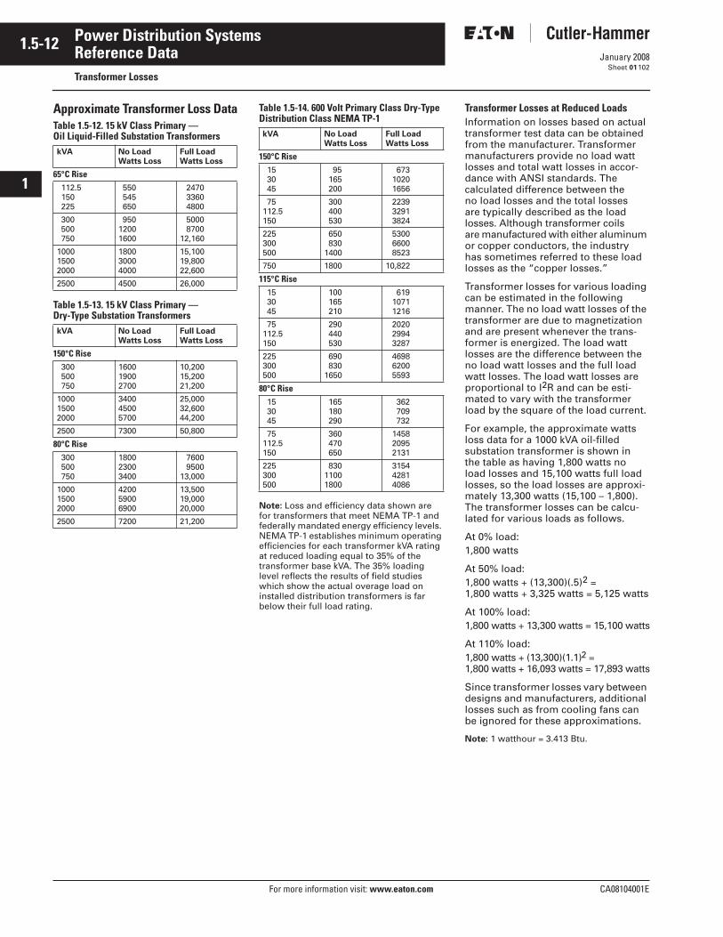
1.5-12
For more information visit: www.eaton.com CA08104001E
January 2008
Power Distribution Systems
i
ii
1
2
3
4
5
6
7
8
9
10
11
12
13
14
15
16
17
18
19
20
21
Sheet 01
Reference DataTransformer Losses
102
Approximate Transformer Loss DataTable 1.5-12. 15 kV Class Primary —Oil Liquid-Filled Substation Transformers
Table 1.5-13. 15 kV Class Primary —Dry-Type Substation Transformers
Table 1.5-14. 600 Volt Primary Class Dry-Type Distribution Class NEMA TP-1
Note: Loss and efficiency data shown are for transformers that meet NEMA TP-1 and federally mandated energy efficiency levels. NEMA TP-1 establishes minimum operating efficiencies for each transformer kVA rating at reduced loading equal to 35% of the transformer base kVA. The 35% loading level reflects the results of field studies which show the actual overage load on installed distribution transformers is far below their full load rating.
Transformer Losses at Reduced LoadsInformation on losses based on actual transformer test data can be obtained from the manufacturer. Transformer manufacturers provide no load watt losses and total watt losses in accor-dance with ANSI standards. The calculated difference between the no load losses and the total losses are typically described as the load losses. Although transformer coils are manufactured with either aluminum or copper conductors, the industry has sometimes referred to these load losses as the “copper losses.”
Transformer losses for various loading can be estimated in the following manner. The no load watt losses of the transformer are due to magnetization and are present whenever the trans-former is energized. The load watt losses are the difference between the no load watt losses and the full load watt losses. The load watt losses are proportional to I2R and can be esti-mated to vary with the transformer load by the square of the load current.
For example, the approximate watts loss data for a 1000 kVA oil-filled substation transformer is shown in the table as having 1,800 watts no load losses and 15,100 watts full load losses, so the load losses are approxi-mately 13,300 watts (15,100 – 1,800). The transformer losses can be calcu-lated for various loads as follows.
At 0% load: 1,800 watts
At 50% load: 1,800 watts + (13,300)(.5)2 = 1,800 watts + 3,325 watts = 5,125 watts
At 100% load: 1,800 watts + 13,300 watts = 15,100 watts
At 110% load: 1,800 watts + (13,300)(1.1)2 = 1,800 watts + 16,093 watts = 17,893 watts
Since transformer losses vary between designs and manufacturers, additional losses such as from cooling fans can be ignored for these approximations.
Note: 1 watthour = 3.413 Btu.
kVA No LoadWatts Loss
Full LoadWatts Loss
65°C Rise 112.5 150 225
550 545 650
2470 3360 4800
300 500 750
95012001600
5000 870012,160
100015002000
180030004000
15,10019,80022,600
2500 4500 26,000
kVA No LoadWatts Loss
Full LoadWatts Loss
150°C Rise 300 500 750
160019002700
10,20015,20021,200
100015002000
340045005700
25,00032,60044,200
2500 7300 50,800
80°C Rise 300 500 750
180023003400
7600 950013,000
100015002000
420059006900
13,50019,00020,000
2500 7200 21,200
kVA No LoadWatts Loss
Full LoadWatts Loss
150°C Rise 15 30 45
95 165 200
673 1020 1656
75112.5150
300 400 530
2239 3291 3824
225300500
650 8301400
5300 6600 8523
750 1800 10,822
115°C Rise 15 30 45
100 165 210
619 1071 1216
75112.5150
290 440 530
2020 2994 3287
225300500
690 8301650
4698 6200 5593
80°C Rise 15 30 45
165 180 290
362 709 732
75112.5150
360 470 650
1458 2095 2131
225300500
83011001800
3154 4281 4086
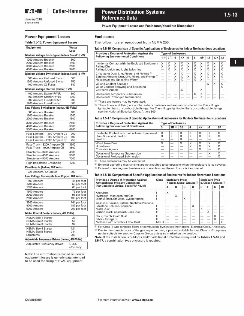
CA08104001E For more information visit: www.eaton.com
1.5-13January 2008
Power Distribution Systems
i
ii
1
2
3
4
5
6
7
8
9
10
11
12
13
14
15
16
17
18
19
20
21
Sheet 01
Reference DataPower Equipment Losses and Enclosures/Knockout Dimensions
103
Power Equipment LossesTable 1.5-15. Power Equipment Losses
Note: The information provided on power equipment losses is generic data intended to be used for sizing of HVAC equipment.
Equipment WattsLoss
Medium Voltage Switchgear (Indoor, 5 and 15 kV)1200 Ampere Breaker2000 Ampere Breaker3000 Ampere Breaker4000 Ampere Breaker
600140021003700
Medium Voltage Switchgear (Indoor, 5 and 15 kV) 600 Ampere Unfused Switch1200 Ampere Unfused Switch 100 Ampere CL Fuses
500 750 840
Medium Voltage Starters (Indoor, 5 kV) 400 Ampere Starter FVNR 800 Ampere Starter FVNR 600 Ampere Fused Switch1200 Ampere Fused Switch
6001000 500 800
Low Voltage Switchgear (Indoor, 480 Volts) 800 Ampere Breaker1600 Ampere Breaker2000 Ampere Breaker
40010001500
3200 Ampere Breaker4000 Ampere Breaker5000 Ampere Breaker
240030004700
Fuse Limiters – 800 Ampere CBFuse Limiters – 1600 Ampere CBFuse Limiters – 2000 Ampere CB
200 500 750
Fuse Truck – 3200 Ampere CBFuse Truck – 4000 Ampere CB
36004500
Structures – 3200 AmpereStructures – 4000 AmpereStructures – 5000 Ampere
400050007000
High Resistance Grounding 1200
Panelboards (Indoor, 480 Volts) 225 Ampere, 42 Circuit 300
Low Voltage Busway (Indoor, Copper, 480 Volts) 800 Ampere1200 Ampere1350 Ampere
44 per foot 60 per foot 66 per foot
1600 Ampere2000 Ampere2500 Ampere
72 per foot 91 per foot 103 per foot
3200 Ampere4000 Ampere5000 Ampere
144 per foot 182 per foot 203 per foot
Motor Control Centers (Indoor, 480 Volts)NEMA Size 1 StarterNEMA Size 2 StarterNEMA Size 3 Starter
39 56 92
NEMA Size 4 StarterNEMA Size 5 StarterStructures
124 244 200
Adjustable Frequency Drives (Indoor, 480 Volts)Adjustable Frequency Drives > 96%
efficiency
EnclosuresThe following are reproduced from NEMA 250.
Table 1.5-16. Comparison of Specific Applications of Enclosures for Indoor Nonhazardous Locations
� These enclosures may be ventilated.� These fibers and flying are nonhazardous materials and are not considered the Class III type
ignitable fibers or combustible flyings. For Class III type ignitable fibers or combustible flyings see the National Electrical Code, Article 500.
Table 1.5-17. Comparison of Specific Applications of Enclosures for Outdoor Nonhazardous Locations
� These enclosures may be ventilated.� External operating mechanisms are not required to be operable when the enclosure is ice covered.� External operating mechanisms are operable when the enclosure is ice covered.
Table 1.5-18. Comparison of Specific Applications of Enclosures for Indoor Hazardous Locations
� For Class III type ignitable fibers or combustible flyings see the National Electrical Code, Article 500.� Due to the characteristics of the gas, vapor, or dust, a product suitable for one Class or Group may
not be suitable for another Class or Group unless so marked on the product.Note: If the installation is outdoors and/or additional protection is required by Tables 1.5-16 and 1.5-17, a combination-type enclosure is required.
Provides a Degree of Protection Against the Following Environmental Conditions
Type of Enclosures
1 � 2 � 4 4X 5 6 6P 12 12K 13
Incidental Contact with the Enclosed EquipmentFalling DirtFalling Liquids and Light Splashing
XX—
XXX
XXX
XXX
XXX
XXX
XXX
XXX
XXX
XXX
Circulating Dust, Lint, Fibers, and Flyings �Settling Airborne Dust, Lint, Fibers, and Flyings �Hosedown and Splashing Water
———
———
XXX
XXX
—X—
XXX
XXX
XX—
XX—
XX—
Oil and Coolant SeepageOil or Coolant Spraying and SplashingCorrosive Agents
———
———
———
——X
———
———
——X
X——
X——
XX—
Occasional Temporary SubmersionOccasional Prolonged Submersion
——
——
——
——
——
X—
XX
——
——
——
Provides a Degree of Protection Against the Following Environmental Conditions
Type of Enclosures
3 3R � 3S 4 4X 6 6P
Incidental Contact with the Enclosed EquipmentRain, Snow and Sleet �Sleet �
XX—
XX—
XXX
XX—
XX—
XX—
XX—
Windblown DustHosedownCorrosive Agents
X——
———
X——
XX—
XXX
XX—
XXX
Occasional Temporary SubmersionOccasional Prolonged Submersion
——
——
——
——
——
X—
XX
Provides a Degree of Protection AgainstAtmospheres Typically Containing (For Complete Listing, See NFPA 497M)
Class Enclosure Types7 and 8, Class I Groups �
Enclosure Type9, Class II Groups �
A B C D E F G 10
AcetyleneHydrogen, Manufactured GasDiethyl Ether, Ethylene, Cyclopropane
III
X——
—X—
——X
———
———
———
———
———
Gasoline, Hexane, Butane, Naphtha, Propane, Acetone, Toluene, IsopreneMetal DustCarbon Black, Coal Dust, Coke Dust
IIIII
———
———
———
X——
—X—
——X
———
———
Flour, Starch, Grain DustFibers, Flyings �
Methane with or without Coal Dust
IIIIIMSHA
———
———
———
———
———
———
XX—
——X
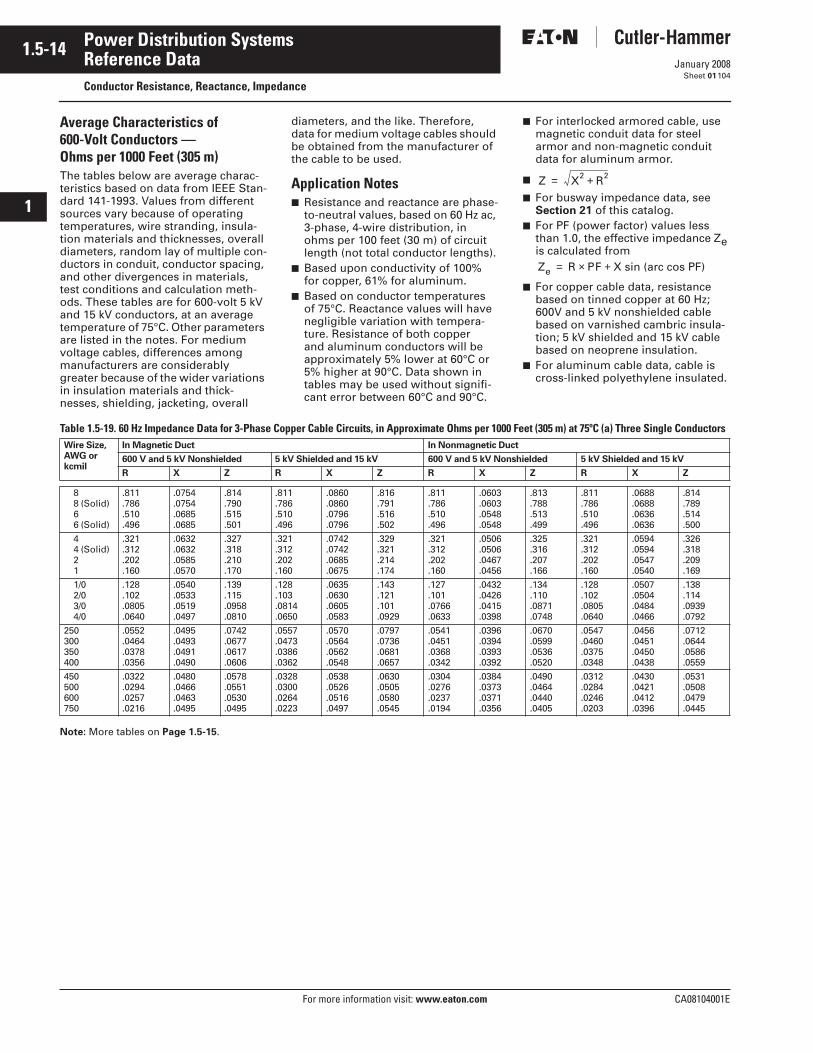
1.5-14
For more information visit: www.eaton.com CA08104001E
January 2008
Power Distribution Systems
i
ii
1
2
3
4
5
6
7
8
9
10
11
12
13
14
15
16
17
18
19
20
21
Sheet 01
Reference DataConductor Resistance, Reactance, Impedance
104
Average Characteristics of 600-Volt Conductors — Ohms per 1000 Feet (305 m)The tables below are average charac-teristics based on data from IEEE Stan-dard 141-1993. Values from different sources vary because of operating temperatures, wire stranding, insula-tion materials and thicknesses, overall diameters, random lay of multiple con-ductors in conduit, conductor spacing, and other divergences in materials, test conditions and calculation meth-ods. These tables are for 600-volt 5 kV and 15 kV conductors, at an average temperature of 75°C. Other parameters are listed in the notes. For medium voltage cables, differences among manufacturers are considerably greater because of the wider variations in insulation materials and thick-nesses, shielding, jacketing, overall
diameters, and the like. Therefore, data for medium voltage cables should be obtained from the manufacturer of the cable to be used.
Application Notes■ Resistance and reactance are phase-
to-neutral values, based on 60 Hz ac, 3-phase, 4-wire distribution, in ohms per 100 feet (30 m) of circuit length (not total conductor lengths).
■ Based upon conductivity of 100% for copper, 61% for aluminum.
■ Based on conductor temperatures of 75°C. Reactance values will have negligible variation with tempera-ture. Resistance of both copper and aluminum conductors will be approximately 5% lower at 60°C or 5% higher at 90°C. Data shown in tables may be used without signifi-cant error between 60°C and 90°C.
■ For interlocked armored cable, use magnetic conduit data for steel armor and non-magnetic conduit data for aluminum armor.
■
■ For busway impedance data, see Section 21 of this catalog.
■ For PF (power factor) values less than 1.0, the effective impedance Ze is calculated from
■ For copper cable data, resistance based on tinned copper at 60 Hz; 600V and 5 kV nonshielded cable based on varnished cambric insula-tion; 5 kV shielded and 15 kV cable based on neoprene insulation.
■ For aluminum cable data, cable is cross-linked polyethylene insulated.
Table 1.5-19. 60 Hz Impedance Data for 3-Phase Copper Cable Circuits, in Approximate Ohms per 1000 Feet (305 m) at 75ºC (a) Three Single Conductors
Note: More tables on Page 1.5-15.
Z X2 R2+=
Ze R PF X sin (arc cos PF)+×=
Wire Size, AWG or kcmil
In Magnetic Duct In Nonmagnetic Duct
600 V and 5 kV Nonshielded 5 kV Shielded and 15 kV 600 V and 5 kV Nonshielded 5 kV Shielded and 15 kV
R X Z R X Z R X Z R X Z
8 8 (Solid) 6 6 (Solid)
.811
.786
.510
.496
.0754
.0754
.0685
.0685
.814
.790
.515
.501
.811
.786
.510
.496
.0860
.0860
.0796
.0796
.816
.791
.516
.502
.811
.786
.510
.496
.0603
.0603
.0548
.0548
.813
.788
.513
.499
.811
.786
.510
.496
.0688
.0688
.0636
.0636
.814
.789
.514
.500
4 4 (Solid) 2 1
.321
.312
.202
.160
.0632
.0632
.0585
.0570
.327
.318
.210
.170
.321
.312
.202
.160
.0742
.0742
.0685
.0675
.329
.321
.214
.174
.321
.312
.202
.160
.0506
.0506
.0467
.0456
.325
.316
.207
.166
.321
.312
.202
.160
.0594
.0594
.0547
.0540
.326
.318
.209
.169
1/0 2/0 3/0 4/0
.128
.102
.0805
.0640
.0540
.0533
.0519
.0497
.139
.115
.0958
.0810
.128
.103
.0814
.0650
.0635
.0630
.0605
.0583
.143
.121
.101
.0929
.127
.101
.0766
.0633
.0432
.0426
.0415
.0398
.134
.110
.0871
.0748
.128
.102
.0805
.0640
.0507
.0504
.0484
.0466
.138
.114
.0939
.0792
250300350400
.0552
.0464
.0378
.0356
.0495
.0493
.0491
.0490
.0742
.0677
.0617
.0606
.0557
.0473
.0386
.0362
.0570
.0564
.0562
.0548
.0797
.0736
.0681
.0657
.0541
.0451
.0368
.0342
.0396
.0394
.0393
.0392
.0670
.0599
.0536
.0520
.0547
.0460
.0375
.0348
.0456
.0451
.0450
.0438
.0712
.0644
.0586
.0559
450500600750
.0322
.0294
.0257
.0216
.0480
.0466
.0463
.0495
.0578
.0551
.0530
.0495
.0328
.0300
.0264
.0223
.0538
.0526
.0516
.0497
.0630
.0505
.0580
.0545
.0304
.0276
.0237
.0194
.0384
.0373
.0371
.0356
.0490
.0464
.0440
.0405
.0312
.0284
.0246
.0203
.0430
.0421
.0412
.0396
.0531
.0508
.0479
.0445
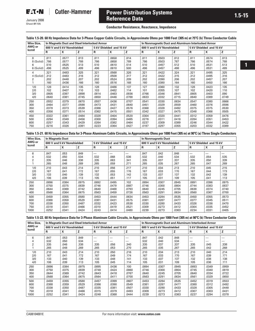
CA08104001E For more information visit: www.eaton.com
1.5-15January 2008
Power Distribution Systems
i
ii
1
2
3
4
5
6
7
8
9
10
11
12
13
14
15
16
17
18
19
20
21
Sheet 01
Reference DataConductor Resistance, Reactance, Impedance
105
Table 1.5-20. 60 Hz Impedance Data for 3-Phase Copper Cable Circuits, in Approximate Ohms per 1000 Feet (305 m) at 75ºC (b) Three Conductor Cable
Table 1.5-21. 60 Hz Impedance Data for 3-Phase Aluminum Cable Circuits, in Approximate Ohms per 1000 Feet (305 m) at 90ºC (a) Three Single Conductors
Table 1.5-22. 60 Hz Impedance Data for 3-Phase Aluminum Cable Circuits, in Approximate Ohms per 1000 Feet (305 m) at 90ºC (b) Three Conductor Cable
Wire Size, AWG or kcmil
In Magnetic Duct and Steel Interlocked Armor In Nonmagnetic Duct and Aluminum Interlocked Armor
600 V and 5 kV Nonshielded 5 kV Shielded and 15 kV 600 V and 5 kV Nonshielded 5 kV Shielded and 15 kV
R X Z R X Z R X Z R X Z
8 8 (Solid) 6 6 (Solid)
.811
.786
.510
.496
.0577
.0577
.0525
.0525
.813
.788
.513
.499
.811
.786
.510
.496
.0658
.0658
.0610
.0610
.814
.789
.514
.500
.811
.786
.510
.496
.0503
.0503
.0457
.0457
.812
.787
.512
.498
.811
.786
.510
.496
.0574
.0574
.0531
.0531
.813
.788
.513
.499
4 4 (Solid) 2 1
.321
.312
.202
.160
.0483
.0483
.0448
.0436
.325
.316
.207
.166
.321
.312
.202
.160
.0568
.0508
.0524
.0516
.326
.317
.209
.168
.321
.312
.202
.160
.0422
.0422
.0390
.0380
.324
.315
.206
.164
.321
.312
.202
.160
.0495
.0495
.0457
.0450
.325
.316
.207
.166
1/0 2/0 3/0 4/0
.128
.102
.0805
.0640
.0414
.0407
.0397
.0381
.135
.110
.0898
.0745
.128
.103
.0814
.0650
.0486
.0482
.0463
.0446
.137
.114
.0936
.0788
.127
.101
.0766
.0633
.0360
.0355
.0346
.0332
.132
.107
.0841
.0715
.128
.102
.0805
.0640
.0423
.0420
.0403
.0389
.135
.110
.090
.0749
250 300 350 400
.0552
.0464
.0378
.0356
.0379
.0377
.0373
.0371
.0670
.0598
.0539
.0514
.0557
.0473
.0386
.0362
.0436
.0431
.0427
.0415
.0707
.0640
.0576
.0551
.0541
.0451
.0368
.0342
.0330
.0329
.0328
.0327
.0634
.0559
.0492
.0475
.0547
.0460
.0375
.0348
.0380
.0376
.0375
.0366
.0666
.0596
.0530
.0505
450 500 600 750
.0322
.0294
.0257
.0216
.0361
.0349
.0343
.0326
.0484
.0456
.0429
.0391
.0328
.0300
.0264
.0223
.0404
.0394
.0382
.0364
.0520
.0495
.0464
.0427
.0304
.0276
.0237
.0197
.0320
.0311
.0309
.0297
.0441
.0416
.0389
.0355
.0312
.0284
.0246
.0203
.0359
.0351
.0344
.0332
.0476
.0453
.0422
.0389
Wire Size, AWG or kcmil
In Magnetic Duct In Nonmagnetic Duct
600 V and 5 kV Nonshielded 5 kV Shielded and 15 kV 600 V and 5 kV Nonshielded 5 kV Shielded and 15 kV
R X Z R X Z R X Z R X Z
6 4 2 1
.847
.532
.335
.265
.053
.050
.046
.048
.849
.534
.338
.269
—.532.335.265
—.068.063.059
—.536.341.271
.847
.532
.335
.265
.042
.040
.037
.035
.848
.534
.337
.267
—.532.335.265
—.054.050.047
—.535.339.269
1/0 2/0 3/0 4/0
.210
.167
.133
.106
.043
.041
.040
.039
.214
.172
.139
.113
.210
.167
.132
.105
.056
.055
.053
.051
.217
.176
.142
.117
.210
.167
.133
.105
.034
.033
.037
.031
.213
.170
.137
.109
.210
.167
.132
.105
.045
.044
.042
.041
.215
.173
.139
.113
250 300 350 400
.0896
.0750
.0644
.0568
.0384
.0375
.0369
.0364
.0975
.0839
.0742
.0675
.0892
.0746
.0640
.0563
.0495
.0479
.0468
.0459
.102
.0887
.0793
.0726
.0894
.0746
.0640
.0563
.0307
.0300
.0245
.0291
.0945
.0804
.0705
.0634
.0891
.0744
.0638
.0560
.0396
.0383
.0374
.0367
.0975
.0837
.0740
.0700
500 600 700 7501000
.0459
.0388
.0338
.0318
.0252
.0355
.0359
.0350
.0341
.0341
.0580
.0529
.0487
.0466
.0424
.0453
.0381
.0332
.0310
.0243
.0444
.0431
.0423
.0419
.0414
.0634
.0575
.0538
.0521
.0480
.0453
.0381
.0330
.0309
.0239
.0284
.0287
.0280
.0273
.0273
.0535
.0477
.0433
.0412
.0363
.0450
.0377
.0326
.0304
.0234
.0355
.0345
.0338
.0335
.0331
.0573
.0511
.0470
.0452
.0405
Wire Size, AWG or kcmil
In Magnetic Duct and Steel Interlocked Armor In Nonmagnetic Duct and Aluminum Interlocked Armor
600 V and 5 kV Nonshielded 5 kV Shielded and 15 kV 600 V and 5 kV Nonshielded 5 kV Shielded and 15 kV
R X Z R X Z R X Z R X Z
6 4 2 1
.847
.532
.335
.265
.053
.050
.046
.048
.849
.534
.338
.269
——.335.265
——.056.053
——.340.270
.847
.532
.335
.265
.042
.040
.037
.035
.848
.534
.337
.267
——.335.265
——.045.042
——.338.268
1/0 2/0 3/0 4/0
.210
.167
.133
.106
.043
.041
.040
.039
.214
.172
.139
.113
.210
.167
.133
.105
.050
.049
.048
.045
.216
.174
.141
.114
.210
.167
.133
.105
.034
.033
.037
.031
.213
.170
.137
.109
.210
.167
.132
.105
.040
.039
.038
.036
.214
.171
.138
.111
250 300 350 400
.0896
.0750
.0644
.0568
.0384
.0375
.0369
.0364
.0975
.0839
.0742
.0675
.0895
.0748
.0643
.0564
.0436
.0424
.0418
.0411
.100
.0860
.0767
.0700
.0894
.0746
.0640
.0563
.0307
.0300
.0245
.0291
.0945
.0804
.0705
.0634
.0893
.0745
.0640
.0561
.0349
.0340
.0334
.0329
.0959
.0819
.0722
.0650
500 600 700 7501000
.0459
.0388
.0338
.0318
.0252
.0355
.0359
.0350
.0341
.0341
.0580
.0529
.0487
.0466
.0424
.0457
.0386
.0335
.0315
.0248
.0399
.0390
.0381
.0379
.0368
.0607
.0549
.0507
.0493
.0444
.0453
.0381
.0330
.0309
.0239
.0284
.0287
.0280
.0273
.0273
.0535
.0477
.0433
.0412
.0363
.0452
.0380
.0328
.0307
.0237
.0319
.0312
.0305
.0303
.0294
.0553
.0492
.0448
.0431
.0378
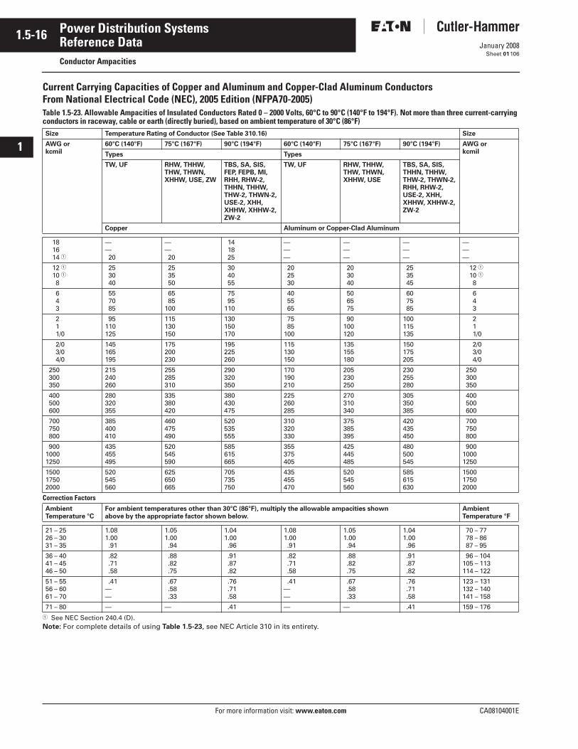
1.5-16
For more information visit: www.eaton.com CA08104001E
January 2008
Power Distribution Systems
i
ii
1
2
3
4
5
6
7
8
9
10
11
12
13
14
15
16
17
18
19
20
21
Sheet 01
Reference DataConductor Ampacities
106
Current Carrying Capacities of Copper and Aluminum and Copper-Clad Aluminum Conductors From National Electrical Code (NEC), 2005 Edition (NFPA70-2005)Table 1.5-23. Allowable Ampacities of Insulated Conductors Rated 0 – 2000 Volts, 60°C to 90°C (140°F to 194°F). Not more than three current-carrying conductors in raceway, cable or earth (directly buried), based on ambient temperature of 30°C (86°F)
� See NEC Section 240.4 (D).Note: For complete details of using Table 1.5-23, see NEC Article 310 in its entirety.
Size Temperature Rating of Conductor (See Table 310.16) Size
AWG orkcmil
60°C (140°F) 75°C (167°F) 90°C (194°F) 60°C (140°F) 75°C (167°F) 90°C (194°F) AWG orkcmilTypes Types
TW, UF RHW, THHW,THW, THWN,XHHW, USE, ZW
TBS, SA, SIS, FEP, FEPB, MI,RHH, RHW-2,THHN, THHW,THW-2, THWN-2,USE-2, XHH,XHHW, XHHW-2, ZW-2
TW, UF RHW, THHW,THW, THWN,XHHW, USE
TBS, SA, SIS,THHN, THHW,THW-2, THWN-2,RHH, RHW-2,USE-2, XHH, XHHW, XHHW-2, ZW-2
Copper Aluminum or Copper-Clad Aluminum
18 16 14 �
—— 20
—— 20
14 18 25
———
———
———
———
12 � 10 � 8
25 30 40
25 35 50
30 40 55
20 25 30
20 30 40
25 35 45
12 � 10 � 8
6 4 3
55 70 85
65 85100
75 95110
40 55 65
50 65 75
60 75 85
6 4 3
2 1 1/0
95110125
115130150
130150170
75 85100
90100120
100115135
2 1 1/0
2/0 3/0 4/0
145165195
175200230
195225260
115130150
135155180
150175205
2/0 3/0 4/0
250 300 350
215240260
255285310
290320350
170190210
205230250
230255280
250 300 350
400 500 600
280320355
335380420
380430475
225260285
270310340
305350385
400 500 600
700 750 800
385400410
460475490
520535555
310320330
375385395
420435450
700 750 800
90010001250
435455495
520545590
585615665
355375405
425445485
480500545
90010001250
150017502000
520545560
625650665
705735750
435455470
520545560
585615630
150017502000
Correction FactorsAmbient Temperature °C
For ambient temperatures other than 30°C (86°F), multiply the allowable ampacities shown above by the appropriate factor shown below.
Ambient Temperature °F
21 – 2526 – 3031 – 35
1.081.00 .91
1.051.00 .94
1.041.00 .96
1.081.00 .91
1.051.00 .94
1.041.00 .96
70 – 77 78 – 86 87 – 95
36 – 4041 – 4546 – 50
.82 .71 .58
.88 .82 .75
.91 .87 .82
.82 .71 .58
.88 .82 .75
.91 .87 .82
96 – 104105 – 113114 – 122
51 – 5556 – 6061 – 70
.41——
.67 .58 .33
.76 .71 .58
.41——
.67 .58 .33
.76 .71 .58
123 – 131132 – 140141 – 158
71 – 80 — — .41 — — .41 159 – 176
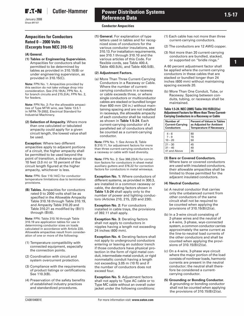
CA08104001E For more information visit: www.eaton.com
1.5-17January 2008
Power Distribution Systems
i
ii
1
2
3
4
5
6
7
8
9
10
11
12
13
14
15
16
17
18
19
20
21
Sheet 01
Reference DataConductor Ampacities
107
Ampacities for Conductors Rated 0 – 2000 Volts(Excerpts from NEC 310-15)
(A) General.(1) Tables or Engineering Supervision.
Ampacities for conductors shall be permitted to be determined by tables as provided in 310.15(B) or under engineering supervision, as provided in 310.15(C).
Note: FPN No. 1: Ampacities provided by this section do not take voltage drop into consideration. See 210.19(A), FPN No. 4,for branch circuits and 215.2(A), FPN No. 2, for feeders.
Note: FPN No. 2: For the allowable ampaci-ties of Type MTW wire, see Table 13.5.1 in NFPA 79-2002, Electrical Standard for Industrial Machinery.
(2) Selection of Ampacity. Where more than one calculated or tabulated ampacity could apply for a given circuit length, the lowest value shall be used.
Exception: Where two different ampacities apply to adjacent portions of a circuit, the higher ampacity shall be permitted to be used beyond the point of transition, a distance equal to 10 feet (3.0 m) or 10 percent of the circuit length figured at the higher ampacity, whichever is less.
Note: FPN: See 110.14(C) for conductor temperature limitations due to termination provisions.
(B) Tables. Ampacities for conductors rated 0 to 2000 volts shall be as specified in the Allowable Ampacity Table 310.16 through Table 310.19, and Ampacity Table 310.20 and Table 310.21 as modified by (B)(1) through (B)(6).
Note: FPN: Table 310.16 through Table 310.19 are application tables for use in determining conductor sizes on loads calculated in accordance with Article 220. Allowable ampacities result from consider-ation of one or more of the following:
(1) Temperature compatibility with connected equipment, especially the connection points.
(2) Coordination with circuit and system overcurrent protection.
(3) Compliance with the requirements of product listings or certifications. See 110.3(B).
(4) Preservation of the safety benefits of established industry practices and standardized procedures.
(1) General. For explanation of type letters used in tables and for recog-nized sizes of conductors for the various conductor insulations, see 310.13. For installation requirements, see 310.1 through 310.10 and the various articles of this Code. For flexible cords, see Table 400.4, Table 400.5(A), and Table 400.5(B).
(2) Adjustment Factors.
(a) More Than Three Current-Carrying Conductors in a Raceway or Cable. Where the number of current-carrying conductors in a raceway or cable exceeds three, or where single conductors or multiconductor cables are stacked or bundled longer than 600 mm (24 in.) without main-taining spacing and are not installed in raceways, the allowable ampacity of each conductor shall be reduced as shown in Table 1.5-24. Each current-carrying conductor of a paralleled set of conductors shall be counted as a current-carrying conductor.
Note: FPN No. 1: See Annex B, Table B.310.11, for adjustment factors for more than three current-carrying conductors in a raceway or cable with load diversity.
Note: FPN No. 2: See 366.23(A) for correc-tion factors for conductors in sheet metal auxiliary gutters and 376.22 for correction factors for conductors in metal wireways.
Exception No. 1: Where conductors of different systems, as provided in 300.3, are installed in a common raceway or cable, the derating factors shown in Table 1.5-24 shall apply only to the number of power and lighting conduc-tors (Articles 210, 215, 220 and 230).
Exception No. 2: For conductors installed in cable trays, the provisions of 392.11 shall apply.
Exception No. 3: Derating factors shall not apply to conductors in nipples having a length not exceeding 24 inches (600 mm).
Exception No. 4: Derating factors shall not apply to underground conductors entering or leaving an outdoor trench if those conductors have physical pro-tection in the form of rigid metal con-duit, intermediate metal conduit, or rigid nonmetallic conduit having a length not exceeding 3.05 m (10 ft) and if the number of conductors does not exceed four.
Exception No. 5: Adjustment factors shall not apply to Type AC cable or to Type MC cable without an overall outer jacket under the following conditions:
(1) Each cable has not more than three current-carrying conductors.
(2) The conductors are 12 AWG copper.
(3) Not more than 20 current-carrying conductors are bundled, stacked, or supported on “bridle rings.”
A 60 percent adjustment factor shall be applied where the current-carrying conductors in these cables that are stacked or bundled longer than 24 inches (600 mm) without maintaining spacing exceeds 20.
(b) More Than One Conduit, Tube, or Raceway. Spacing between con-duits, tubing, or raceways shall be maintained.
Table 1.5-24. NEC (2005) Table 310.15(B)(2)(a) Adjustment Factors for More than Three Current-Carrying Conductors in a Raceway or Cable
(3) Bare or Covered Conductors. Where bare or covered conductors are used with insulated conductors, their allowable ampacities shall be limited to those permitted for the adjacent insulated conductors.
(4) Neutral Conductor.
(a) A neutral conductor that carries only the unbalanced current from other conductors of the same circuit shall not be required to be counted when applying the provisions of 310.15(B)(2)(a).
(b) In a 3-wire circuit consisting of 2-phase wires and the neutral of a 4-wire, 3-phase, wye-connected system, a common conductor carries approximately the same current as the line-to-neutral load currents of the other conductors and shall be counted when applying the provi-sions of 310.15(B)(2)(a).
(c) On a 4-wire, 3-phase wye circuit where the major portion of the load consists of nonlinear loads, harmonic currents are present in the neutral conductor; the neutral shall there-fore be considered a current-carrying conductor.
(5) Grounding or Bonding Conductor. A grounding or bonding conductor shall not be counted when applying the provisions of 310.15(B)(2)(a).
Number ofCurrent-Carrying Conductors
Percent of Values in Tables as Adjusted for Ambient Temperature if Necessary
4 – 6 7 – 910 – 20
807050
21 – 3031 – 4041 and Above
454035
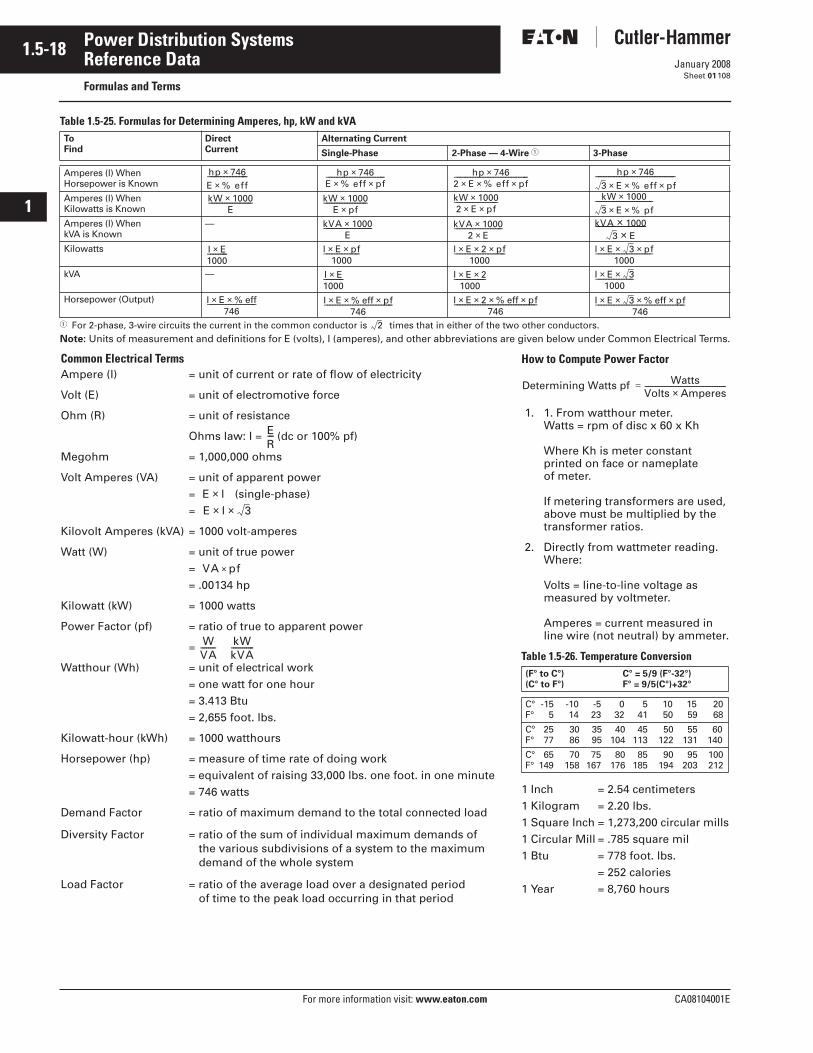
1.5-18
For more information visit: www.eaton.com CA08104001E
January 2008
Power Distribution Systems
i
ii
1
2
3
4
5
6
7
8
9
10
11
12
13
14
15
16
17
18
19
20
21
Sheet 01
Reference DataFormulas and Terms
108
Table 1.5-25. Formulas for Determining Amperes, hp, kW and kVA
� For 2-phase, 3-wire circuits the current in the common conductor is times that in either of the two other conductors.Note: Units of measurement and definitions for E (volts), I (amperes), and other abbreviations are given below under Common Electrical Terms.
To Find
Direct Current
Alternating Current
Single-Phase 2-Phase — 4-Wire � 3-Phase
Amperes (l) WhenHorsepower is Known
Amperes (l) WhenKilowatts is Known
Amperes (l) WhenkVA is Known
—
Kilowatts
kVA —
Horsepower (Output)
hp 746×E % eff×−−−−−−−−−−−−− hp 746×
E % eff× pf×−−−−−−−−−−−−−−−−−−−−−−− hp 746×
2 E× % eff× pf×−−−−−−−−−−−−−−−−−−−−−−−−−−−−− hp 746×
3 E× % eff× pf×−−−−−−−−−−−−−−−−−−−−−−−−−−−−−−−
kW 1000×E
−−−−−−−−−−−−−−−−− kW 1000×E pf×
−−−−−−−−−−−−−−−−− kW 1000×2 E× pf×
−−−−−−−−−−−−−−−−− kW 1000×3 E× % pf×
−−−−−−−−−−−−−−−−−−−−−−
kVA 1000×E
−−−−−−−−−−−−−−−−−−− kVA 1000×2 E×
−−−−−−−−−−−−−−−−−−− kVA 1000×3 E×
−−−−−−−−−−−−−−−−
I E×1000−−−−−−−− l E× pf×
1000−−−−−−−−−−−−−− l E 2×× pf×
1000−−−−−−−−−−−−−−−−−−−− l E 3×× pf×
1000−−−−−−−−−−−−−−−−−−−−−−
I E×1000−−−−−−−− I E 2××
1000−−−−−−−−−−−− I E 3××
1000−−−−−−−−−−−−−−−
I E× % eff×746
−−−−−−−−−−−−−−−−−−− I E× % eff pf××746
−−−−−−−−−−−−−−−−−−−−−−−−−−− I E 2×× % eff pf××746
−−−−−−−−−−−−−−−−−−−−−−−−−−−−−−−− I E 3×× % eff pf××746
−−−−−−−−−−−−−−−−−−−−−−−−−−−−−−−−−−−
2
Common Electrical TermsAmpere (l) = unit of current or rate of flow of electricity
Volt (E) = unit of electromotive force
Ohm (R) = unit of resistance
Ohms law: I = (dc or 100% pf)
Megohm = 1,000,000 ohms
Volt Amperes (VA) = unit of apparent power= (single-phase)=
Kilovolt Amperes (kVA) = 1000 volt-amperes
Watt (W) = unit of true power= = .00134 hp
Kilowatt (kW) = 1000 watts
Power Factor (pf) = ratio of true to apparent power
=
Watthour (Wh) = unit of electrical work= one watt for one hour= 3.413 Btu= 2,655 foot. lbs.
Kilowatt-hour (kWh) = 1000 watthours
Horsepower (hp) = measure of time rate of doing work= equivalent of raising 33,000 lbs. one foot. in one minute= 746 watts
Demand Factor = ratio of maximum demand to the total connected load
Diversity Factor = ratio of the sum of individual maximum demands of the various subdivisions of a system to the maximum demand of the whole system
Load Factor = ratio of the average load over a designated period of time to the peak load occurring in that period
ER−−
E l×E l× 3×
VA pf×
WVA-------- kW
kVA------------
How to Compute Power Factor
1. 1. From watthour meter.Watts = rpm of disc x 60 x Kh
Where Kh is meter constant printed on face or nameplate of meter.
If metering transformers are used, above must be multiplied by the transformer ratios.
2. Directly from wattmeter reading.Where:
Volts = line-to-line voltage as measured by voltmeter.
Amperes = current measured in line wire (not neutral) by ammeter.
Table 1.5-26. Temperature Conversion
1 Inch = 2.54 centimeters1 Kilogram = 2.20 lbs.1 Square Inch = 1,273,200 circular mills1 Circular Mill = .785 square mil1 Btu = 778 foot. lbs.
= 252 calories1 Year = 8,760 hours
(F° to C°) C° = 5/9 (F°-32°)(C° to F°) F° = 9/5(C°)+32°
C° -15 -10 -5 0 5 10 15 20F° 5 14 23 32 41 50 59 68
Cº 25 30 35 40 45 50 55 60F° 77 86 95 104 113 122 131 140
C° 65 70 75 80 85 90 95 100F° 149 158 167 176 185 194 203 212
Determining Watts pf WattsVolts Amperes×----------------------------------------------=
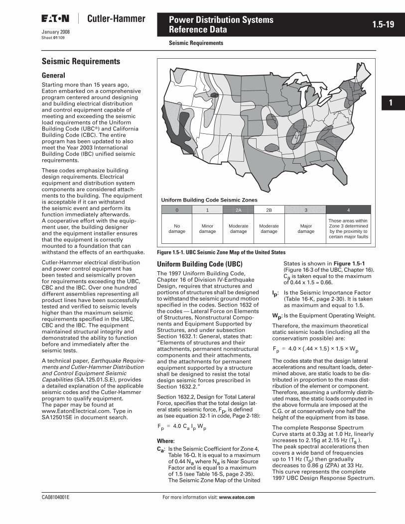
CA08104001E For more information visit: www.eaton.com
1.5-19January 2008
Power Distribution Systems
i
ii
1
2
3
4
5
6
7
8
9
10
11
12
13
14
15
16
17
18
19
20
21
Sheet 01
Reference DataSeismic Requirements
109
Seismic Requirements
GeneralStarting more than 15 years ago, Eaton embarked on a comprehensive program centered around designing and building electrical distribution and control equipment capable of meeting and exceeding the seismic load requirements of the Uniform Building Code (UBC�) and California Building Code (CBC). The entire program has been updated to also meet the Year 2003 International Building Code (IBC) unified seismic requirements.
These codes emphasize building design requirements. Electrical equipment and distribution system components are considered attach-ments to the building. The equipment is acceptable if it can withstand the seismic event and perform its function immediately afterwards. A cooperative effort with the equip-ment user, the building designer and the equipment installer ensures that the equipment is correctly mounted to a foundation that can withstand the effects of an earthquake.
Cutler-Hammer electrical distribution and power control equipment has been tested and seismically proven for requirements exceeding the UBC, CBC and the IBC. Over one hundred different assemblies representing all product lines have been successfully tested and verified to seismic levels higher than the maximum seismic requirements specified in the UBC, CBC and the IBC. The equipment maintained structural integrity and demonstrated the ability to function before and immediately after the seismic tests.
A technical paper, Earthquake Require-ments and Cutler-Hammer Distribution and Control Equipment Seismic Capabilities (SA.125.01.S.E), provides a detailed explanation of the applicable seismic codes and the Cutler-Hammer program to qualify equipment. The paper may be found at www.EatonElectrical.com. Type in SA12501SE in document search.
Figure 1.5-1. UBC Seismic Zone Map of the United States
Uniform Building Code (UBC)The 1997 Uniform Building Code, Chapter 16 of Division IV-Earthquake Design, requires that structures and portions of structures shall be designed to withstand the seismic ground motion specified in the codes. Section 1632 of the codes — Lateral Force on Elements of Structures, Nonstructural Compo-nents and Equipment Supported by Structures, and under subsection Section 1632.1: General, states that: “Elements of structures and their attachments, permanent nonstructural components and their attachments, and the attachments for permanent equipment supported by a structure shall be designed to resist the total design seismic forces prescribed in Section 1632.2.”
Section 1632.2, Design for Total Lateral Force, specifies that the total design lat-eral static seismic force, Fp, is defined as (see equation 32-1 in code, Page 2-18):
Where:Ca: Is the Seismic Coefficient for Zone 4,
Table 16-Q. It is equal to a maximumof 0.44 Na where Na is Near SourceFactor and is equal to a maximum of 1.5 (see Table 16-S, page 2-35). The Seismic Zone Map of the United
States is shown in Figure 1.5-1 (Figure 16-3 of the UBC, Chapter 16). Ca is taken equal to the maximum of 0.44 x 1.5 = 0.66.
Ip: Is the Seismic Importance Factor (Table 16-K, page 2-30). It is taken as maximum and equal to 1.5.
Wp: Is the Equipment Operating Weight.
Therefore, the maximum theoretical static seismic loads (including all the conservatism possible) are:
The codes state that the design lateral accelerations and resultant loads, deter-mined above, are static loads to be dis-tributed in proportion to the mass dist-ribution of the element or component. Therefore, assuming a uniformly distrib-uted mass, the static loads computed in the above formula are imposed at the C.G. or at conservatively one half the height of the equipment from its base.
The complete Response Spectrum Curve starts at 0.33g at 1.0 Hz, linearly increases to 2.15g at 2.15 Hz (Ts ). The peak spectral accelerations then covers a wide band of frequencies up to 11 Hz (To) then gradually decreases to 0.86 g (ZPA) at 33 Hz. This curve represents the complete 1997 UBC Design Response Spectrum.
Uniform Building Code Seismic Zones
0
Nodamage
1
Minordamage
2A
Moderatedamage
2B
Moderatedamage
3
Majordamage
4
Those areas within Zone 3 determinedby the proximity tocertain major faults
Fp 4.0 Ca Ip Wp=
Fp 4.0 .44 1.5×( ) 1.5 Wp×××=
1.5-20
For more information visit: www.eaton.com CA08104001E
January 2008
Power Distribution Systems
i
ii
1
2
3
4
5
6
7
8
9
10
11
12
13
14
15
16
17
18
19
20
21
Sheet 01
Reference DataSeismic Requirements
110
California Building CodeCalifornia Building Code adopted the 1997 UBC as the CBC-Title 24. The seis-mic requirements are basically the same as described in the UBC. When consider-ing the maximum seismic requirements, the UBC and CBC are basically identical.
Again, as in the UBC, the Response Spectrum Curve starts at 0.33g at 1.0 Hz, linearly increases to 2.15g at 2.15 Hz (Ts). The peak spectral accelerations then cover a wide band of frequencies up to 11 Hz (To) then gradually decreasesto 0.86g (ZPA) at 33 Hz.
ANSI C37.81The seismic requirements for Class 1E switchgear in nuclear power plants are defined in ANSI C37.81. Eaton elected to test the equipment to 2/3 of the nuclear requirements.
Year 2003 International Building Code (IBC)On December 9, 1994, the International Code Council (ICC) was established as a nonprofit organization dedicated to developing a single set of comprehen-sive and coordinated national codes.
The ICC founders — the Building Offi-cials and Code Administrators (BOCA), the International Conference of Build-ing Officials (ICBO), and the Southern Building Code Congress International (SBCCI�) — created the ICC in response to technical disparities among the three nationally recognized model codes now in use in the U.S. The ICC offers a single, complete set of con-struction codes without regional limi-tations — the International IBC Codes.
According to Chapter 16, Structure Design, the seismic requirements of electrical equipment in buildings may be computed in two steps. The first step is to determine the maximum ground motion to be considered at the site. The second step is to evaluate the equipment mounting and attachments inside the building or structure. The two sets are then evaluated to determine appropriate seismic test requirements. The ground motion, the in-structure seismic requirements of the equipment, and the seismic response spectrum requirements are discussed below.
A. Ground MotionAccording to the code, the first and most important step in the process is to determine the Maximum Considered Earthquake Spectral Response Accel-eration at short periods of 0.2 seconds (SS) and at a period of 1.0 second (S1). These values are determined from a set of 24 Spectral Acceleration Maps which include numerous contour lines indicating the severity of the earthquake requirements at a particular location in the country.
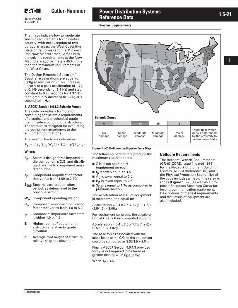
CA08104001E For more information visit: www.eaton.com
1.5-21January 2008
Power Distribution Systems
i
ii
1
2
3
4
5
6
7
8
9
10
11
12
13
14
15
16
17
18
19
20
21
Sheet 01
Reference DataSeismic Requirements
111
The maps indicate low to moderate seismic requirements for the entire country, with the exception of two particular areas; the West Coast (the State of California) and the Midwest (the New Madrid areas). Areas with the seismic requirements at the New Madrid are approximately 40% higher than the maximum requirements of the West Coast.
The Design Response Spectrum/Spectral accelerations are equal to 0.68g at zero period (ZPA), increase linearly to a peak acceleration of 1.7g at 0.146 seconds (or 6.9 Hz) and stay constant to 0.73 seconds (or 1.37 Hz) then gradually decrease to 1.24g at 1 second (or 1 Hz).
B. ASCE7 Section 9.6.1.3 Seismic ForcesThe code provides a formula for computing the seismic requirements of electrical and mechanical equip-ment inside a building or a structure. The formula is designed for evaluating the equipment attachment to the equipment foundations.
The seismic loads are defined as:
Where:
Fp: Seismic design force imposed at the component’s C.G. and distrib-uted relative to component mass distribution.
ap: Component amplification factor that varies from 1.00 to 2.50.
SDS: Spectral acceleration, short period, as determined in the previous section.
Wp: Component operating weight.
Rp: Component response modification factor that varies from 1.0 to 5.0.
Ip: Component importance factor that is either 1.0 or 1.5.
Z: Highest point of equipment in a structure relative to grade elevation.
h: Average roof height of structure relative to grade elevation.
Fp .4ap SDS Wp 1 2 Z h⁄+( ) Rp Ip⁄( )⁄=Figure 1.5-2. Bellcore Earthquake Zone Map
The following parameters produce the maximum required force:
■ Z is taken equal to H (equipment on roof).
■ Ip is taken equal to 1.5.■ Ap is taken equal to 2.5.■ Rp is taken equal to 2.5.■ SDS is equal to 1.7g as computed in
previous section.
The acceleration at C.G. of equipment is then computed equal to:
Acceleration = 0.4 x 2.5 x 1.7g (1 + 2) / (2.5/1.5) = 3.06g
For equipment on grade, the accelera-tion at C.G. is then computed equal to:
Acceleration = 0.4 x 2.5 x 1.7g (1 + 0) / (2.5 /1.5) = 1.02g
The base forces associated with the static loads at the C.G. of the equipment could be computed as 3.06/1.5 = 2.04g.
Finally ASCE7 Section 9.6.1.3 provides for FP is not required to be taken as greater than FP = 1.6 SDS IP WP
When IP = 1.5
Bellcore RequirementsThe Bellcore Generic Requirements (GR-63-CORE, Issue 1, dated 1995) for the Network Equipment-Building System (NEBS) (Reference 10), and the Physical Protection Section 5.4 of the code includes a map of the seismic zones (Figure 1.5-2), as well as a pro-posed Response Spectrum Curve for testing communication equipment. Descriptions of the test requirements and test levels of equipment are also included.
Seismic Zones
0
Nodamage
1
Minordamage
2A
Moderatedamage
2B
Moderatedamage
3
Majordamage
4
Those areas within Zone 3 determinedby the proximity tocertain major faults
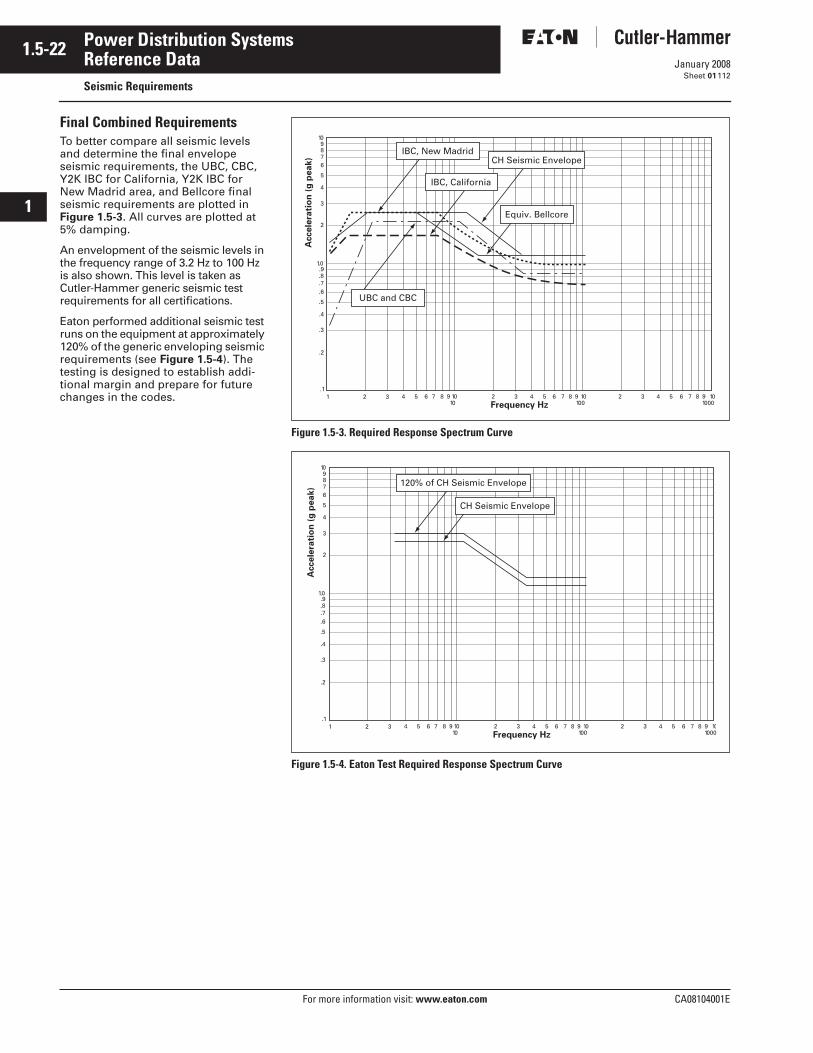
1.5-22
For more information visit: www.eaton.com CA08104001E
January 2008
Power Distribution Systems
i
ii
1
2
3
4
5
6
7
8
9
10
11
12
13
14
15
16
17
18
19
20
21
Sheet 01
Reference DataSeismic Requirements
112
Final Combined RequirementsTo better compare all seismic levels and determine the final envelope seismic requirements, the UBC, CBC, Y2K IBC for California, Y2K IBC for New Madrid area, and Bellcore final seismic requirements are plotted in Figure 1.5-3. All curves are plotted at 5% damping.
An envelopment of the seismic levels in the frequency range of 3.2 Hz to 100 Hz is also shown. This level is taken as Cutler-Hammer generic seismic test requirements for all certifications.
Eaton performed additional seismic test runs on the equipment at approximately 120% of the generic enveloping seismic requirements (see Figure 1.5-4). The testing is designed to establish addi-tional margin and prepare for future changes in the codes.
Figure 1.5-3. Required Response Spectrum Curve
Figure 1.5-4. Eaton Test Required Response Spectrum Curve
IBC, New Madrid
UBC and CBC
IBC, California
Equiv. Bellcore
1.1
.2
.3
.4
.5
.6
.7
.8
.9
2
3
4
5
6789
10
1. 0
2 3 4 5 6 7 8 9 10 2 3 4 5 6 7 8 9 10100
3 4 5 6 7 8 9 102
Frequency Hz
Accele
rati
on
(g
peak)
10 1000
CH Seismic Envelope
120% of CH Seismic Envelope
CH Seismic Envelope
1.1
.2
.3
.4
.5
.6
.7
.8
.9
2
3
4
5
6789
10
1. 0
2 3 4 5 6 7 8 9 10 2 3 4 5 6 7 8 9 10100
3 4 5 6 7 8 9 102
Frequency Hz
Accele
rati
on
(g
peak)
10 1000
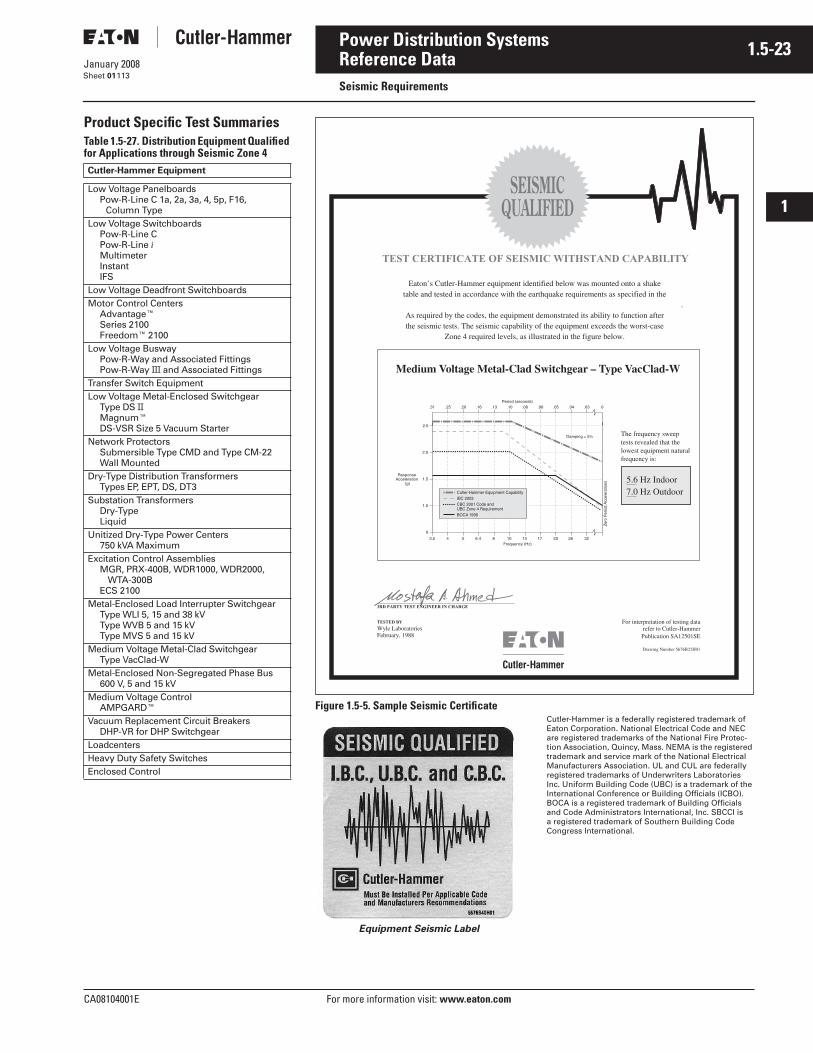
CA08104001E For more information visit: www.eaton.com
1.5-23January 2008
Power Distribution Systems
i
ii
1
2
3
4
5
6
7
8
9
10
11
12
13
14
15
16
17
18
19
20
21
Sheet 01
Reference DataSeismic Requirements
113
Product Specific Test SummariesTable 1.5-27. Distribution Equipment Qualified for Applications through Seismic Zone 4Cutler-Hammer Equipment
Low Voltage PanelboardsPow-R-Line C 1a, 2a, 3a, 4, 5p, F16,
Column TypeLow Voltage Switchboards
Pow-R-Line CPow-R-Line iMultimeterInstantIFS
Low Voltage Deadfront SwitchboardsMotor Control Centers
Advantage�Series 2100Freedom� 2100
Low Voltage BuswayPow-R-Way and Associated FittingsPow-R-Way III and Associated Fittings
Transfer Switch EquipmentLow Voltage Metal-Enclosed Switchgear
Type DS IIMagnum�DS-VSR Size 5 Vacuum Starter
Network ProtectorsSubmersible Type CMD and Type CM-22Wall Mounted
Dry-Type Distribution TransformersTypes EP, EPT, DS, DT3
Substation TransformersDry-TypeLiquid
Unitized Dry-Type Power Centers750 kVA Maximum
Excitation Control AssembliesMGR, PRX-400B, WDR1000, WDR2000,
WTA-300BECS 2100
Metal-Enclosed Load Interrupter SwitchgearType WLI 5, 15 and 38 kVType WVB 5 and 15 kVType MVS 5 and 15 kV
Medium Voltage Metal-Clad SwitchgearType VacClad-W
Metal-Enclosed Non-Segregated Phase Bus600 V, 5 and 15 kV
Medium Voltage ControlAMPGARD�
Vacuum Replacement Circuit BreakersDHP-VR for DHP Switchgear
LoadcentersHeavy Duty Safety SwitchesEnclosed Control
Figure 1.5-5. Sample Seismic Certificate
Equipment Seismic Label
Cutler-Hammer is a federally registered trademark of Eaton Corporation. National Electrical Code and NEC are registered trademarks of the National Fire Protec-tion Association, Quincy, Mass. NEMA is the registered trademark and service mark of the National Electrical Manufacturers Association. UL and CUL are federally registered trademarks of Underwriters Laboratories Inc. Uniform Building Code (UBC) is a trademark of the International Conference or Building Officials (ICBO). BOCA is a registered trademark of Building Officials and Code Administrators International, Inc. SBCCI is a registered trademark of Southern Building Code Congress International.

1.5-24
For more information visit: www.eaton.com CA08104001E
January 2008
Power Distribution Systems
i
ii
1
2
3
4
5
6
7
8
9
10
11
12
13
14
15
16
17
18
19
20
21
Sheet 01114
This page intentionally left blank.