Cutler-Hammer - Electrical Part Manual S · safety procedures. cutler-hammer is not liable for the...
76
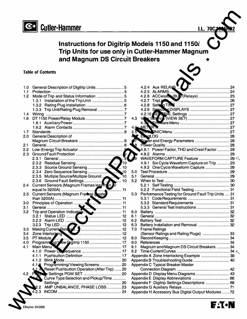
l I Cutler-Hammer I.L. 70C1036H02 Instructions for Digitrip Models 1150 and 1150i Trip Units for use only in Cutler-Hammer Magnum and Magnum DS Circuit Breakers Table of Contents 1.0 General Description of Digitrip Units ........ ............. .... 5 1.1 Protection . .......................... ................... ................... 5 1.2 Mode of Trip and Status Information ............ ............. 5 1.3.1 Installation of the Trip Unit ............. ................ 5 1.3.2 Rating Plug Installation .................................. 6 1.3.3 Trip Unit/Rating Plug Removal . . ..................... 7 1.4 Wiring ...................................................................... 7 1.6 DT 1150 Power/Relay Module ................................... 7 1.6.1 Auxilia Power .............................................. 7 1.6.2 Alarm Contacts .............................................. 7 1.7 Standards . . . . ............. .. .......... .... ............... ................. 8 2.0 General Description of Magnum Circuit Breake ......... . ........ ....................... 8 2.1 General ....... .. ........................... . ....... ......................... 8 2.2 Low-Energy Trip Actuator ...... .. .. . ......................... . .... 9 2.3 Ground Fault Protection ...................... ..................... 9 2.3.1 General ................................. ........... .... .......... 9 2.3.2 Residual Sensing ................ ... . . . ................... 10 2.3.3 Source Ground Sensing . .. . ........................... 10 2.3.4 Zero Sequence Sensing ............................... 10 2.3.5 Multiple Source/Multiple Ground .................. 10 2.3.6 Ground Fault Settings .................................. 10 2.4 Current Sensors (Magnum Frames less than or equal to 3200A) .......... .......... .......................... ........ 11 2.5 Current Senso (Magnum Frames greater than 3200A) ............................. . ......................... . . . . . 11 3.0 Principles of Operation ........................................... 1 1 3.1 General .............................. . . . ........... ........ . . . ............ 11 3.2 Trip and Operation Indicato ......... . . . . ............ . . . ...... 1 1 3.2.1 Status LED ...................................... ............ 12 3.2.2 Alarm LED . .. ............... .. ........................... .... 12 3.2.3 Trip LED ............................. ......... . .......... . .... . 12 3.3 Making Current Release ....... .............. .............. ...... 12 3.4 Zone Interlocking ............. . .. . . ...... .. .. ... . . .. . . .. .. . . . . . ...... 12 3.5 PT Module ................... ............. . ..... ............... ......... 12 4.0 Programming/View Digitrip 1150 ............... . ............. 17 4.1 Main Menu ................... ....................... ............ ....... 17 4.1.0 Power Up Sequence .. ................ .................. 17 4.1.1 Pushbutton Definition ................................... 17 4.1.2 Blink Mode .............. . .......... ............. ............. 4 4.1.3 ProgramminViewing Screens .................... 4 4.1.4 Reset Pushbutton Operation (After Trip) ...... 4 4.2 Program Settings PG M SET ...................... . . . ......... 20 4.2.1 Cue Type Selection and Pickupffime .......... .. Settings ... .................................................... 4 4.2 .2 AMP UNBALANCE, PHASE LOSS ............. 23 4.2.3 INCOM .............. ....................... . ............... .... 24 Effective 03/2000 4.2.4 Aux RELAYS . . . ...... .. .. . ....... .. ........................ 24 4.2.5 ALARMS ...................................................... 24 4.2.6 ACCesso BUS (Relays) ................... ......... 25 4.2.7 TripUnk ...................... ... ............................... : 4.2.8 Setting TIME ................................................ 27 4.2.9 Selecting DISPLAYS ... ... ..................... ........ 27 4.2.1 0 GENERAL Settings ............ ......................... 27 4.3 View Settings (VIEW SET) ..................................... 27 4.3.1 Firmware Menu .............. ... .. ...... .... ............... 27 4.4 METER ... ................................................................ 27 4.5 HARMONIC Menu .. ............... ...... .. .. . . ..................... 27 4.6 EventLOG ............................. . .................... . ............ 28 4.7 Power and Energy Parameters . ............... ............. .. 28 4.8 Power Quality ......................................................... 28 4.8.1 Power Factor, THO and Crest Factor ........... 28 4.8.2 Alarms ....... .......... . ..... ...... ........... ................. 29 4.9 WAVEFORM CAPTURE Feature ...................... ..... = 4.9.1 Six Cycle Waveform Capture on Trip .. . ........ 29 4.9.2 One Cycle Waveform Capture ...................... = 5.0 Test Procedure ............................. .......................... = 5.1 Genel ...................................................... . ......... ... = 5.2 When to Test .......................................................... > 5.2.1 Self Testing .................................................. > 5.2.2 Functional Field Testing ............... ........ ........ 31 5.3 Perfoance Testing for Ground Fault Trip Units . . .. 31 5.3.1 Code Requirements ......................... .... ..... ... 31 5.3.2 Standard Requirements ............................... 31 5.3.3 General Test Instructions ..... . ....................... 31 6.0 Batte .......................... .......... .. .... .... ......... ............ 6. 1 General ................................................................... 6.2 Baery Test ................................ .................. .......... 6.3 Battery Installation and Removal ....................... ..... 7.0 Frame Ratings (Sensor Ratings and Rating Plugs) ........................ ! 8.0 Record Keeping ..... ................................................. " 9.0 References ............................................................. " 9.1 Magnum and Magnum OS Circuit Breakers ........... " 9.2 Time-Curnt Cues ............................................... " � Appendix A Zone Interlocking Example .................... ..... ' Appendix B Troubleshooting Guide ............................ .... ( Appendix C Typical Breaker Master Connection Diagram ............................................... * Appendix D Display Menu Diagrams .... ................ .......... + Appendix E Display Abbreviations .. ............ ............ .. ..... B Appendix F Digitrip Seings Descriptions ..................... D Appendix G Auxiliary Relays .......... ...... . ......................... 71 Appendix H Accesso Bus Digital Output Modules ...... 72 www . ElectricalPartManuals . com
Transcript of Cutler-Hammer - Electrical Part Manual S · safety procedures. cutler-hammer is not liable for the...
ltCCJI Cutler-Hammer I.L. 70C1036H02
Instructions for Digitrip Models 1150 and 1150i Trip Units for use only in Cutler-Hammer Magnum and Magnum DS Circuit Breakers
Table of Contents
1.0 General Description of Digitrip Units ........ ................. 5 1.1 Protection . ................................................................ 5 1.2 Mode of Trip and Status Information ......................... 5
1.3.1 Installation of the Trip Unit ............................. 5 1.3.2 Rating Plug Installation .................................. 6 1.3.3 Trip Unit/Rating Plug Removal ....................... 7
1.4 Wiring ...................................................................... 7 1.6 DT 1150 Power/Relay Module ................................... 7
1.6.1 Auxiliary Power .............................................. 7 1.6.2 Alarm Contacts .............................................. 7
1.7 Standards . .. ............... ............................................... 8 2.0 General Description of
Magnum Circuit Breakers ......... . ............................... 8 2.1 General ............................................ ......................... 8 2.2 Low-Energy Trip Actuator ....... .................................. 9 2.3 Ground Fault Protection ...................... ..................... 9
2.3.1 General .......................................................... 9 2.3.2 Residual Sensing ................... .. .................... 10 2.3.3 Source Ground Sensing .... ........................... 10 2.3.4 Zero Sequence Sensing ............................... 10 2.3.5 Multiple Source/Multiple Ground .................. 10 2.3.6 Ground Fault Settings .................................. 10
2.4 Current Sensors (Magnum Frames less than or equal to 3200A) .................... .................................. 11
2.5 Current Sensors (Magnum Frames greater than 3200A) .............................. .............................. 11
3.0 Principles of Operation ........................................... 11 3.1 General .............................. .. ....................... ............ 11 3.2 Trip and Operation Indicators ......... . .. ...................... 11
3.2.1 Status LED .................................................. 12 3.2.2 Alarm LED . . ................. ................................ 12 3.2.3 Trip LED ....................................... . . .............. 12
3.3 Making Current Release ....... .................................. 12 3.4 Zone Interlocking ............. .... ........ .... . . . . ..... . ............. 12 3.5 PT Module ................... ................................. .......... 12 4.0 Programming/View Digitrip 1150 ............................. 17 4.1 Main Menu ............................................................. 17
4.1.0 Power Up Sequence .................................... 17 4.1.1 Pushbutton Definition ................................... 17 4.1.2 Blink Mode ...................................... ............. 20 4.1.3 Programming/Viewing Screens .................... 20 4.1.4 Reset Pushbutton Operation (After Trip) ...... 20
4.2 Program Settings PG M SET .................................. 20 4.2.1 Curve Type Selection and Pickupffime .......... ..
Settings ....................................................... 20 4.2.2 AMP UNBALANCE, PHASE LOSS ............. 23 4.2.3 INCOM ......................................................... 24
Effective 03/2000
4.2.4 Aux RELAYS .......... ........... . . ........................ 24 4.2.5 ALARMS ...................................................... 24 4.2.6 ACCessory BUS (Relays) ............................ 25 4.2.7 TripUnk ................... . .. .. . ............................... 26 4.2.8 Setting TIME ................................................ 27 4.2.9 Selecting DISPLAYS ........................... ........ 27 4.2.1 0 GENERAL Settings ............ ......................... 27
4.3 View Settings (VIEW SET) ..................................... 27 4.3.1 Firmware Menu ................. . . ......................... 27
4.4 METER ................................................................... 27 4.5 HARMONIC Menu . . ............... ....... . ......................... 27 4.6 EventLOG ............................. .................................. 28 4.7 Power and Energy Parameters ................ ............... 28 4.8 Power Quality ......................................................... 28
4.8.1 Power Factor, THO and Crest Factor ........... 28 4.8.2 Alarms ......................................................... 29
4.9 WAVEFORM CAPTURE Feature ...................... ..... 29 4.9.1 Six Cycle Waveform Capture on Trip ........... 29 4.9.2 One Cycle Waveform Capture ...................... 29
5.0 Test Procedure .................. ........... . . ........................ 29 5.1 General ...................................................... .......... ... 29 5.2 When to Test .......................................................... 30
5.2.1 Self Testing .................................................. 30 5.2.2 Functional Field Testing ....................... ........ 31
5.3 Performance Testing for Ground Fault Trip Units .... 31 5.3.1 Code Requirements ..................................... 31 5.3.2 Standard Requirements ............................... 31 5.3.3 General Test Instructions ..... ........................ 31
6.0 Battery ................................... . . .............................. 32 6. 1 General ................................................................... 32 6.2 Battery Test ................................................. . .......... 32 6.3 Battery Installation and Removal ....................... ..... 32 7.0 Frame Ratings
(Sensor Ratings and Rating Plugs) ........................ 33 8.0 Record Keeping .... . ................................................. 34 9.0 References .................. ........................................... 34 9.1 Magnum and Magnum OS Circuit Breakers ........... 34 9.2 Time-Current Curves ............................................... 34 � Appendix A Zone Interlocking Example .................... ..... 39 Appendix B Troubleshooting Guide ........................... ..... 40 Appendix C Typical Breaker Master
Connection Diagram ....................................... ........ 42 Appendix D Display Menu Diagrams ..... ......................... 43 Appendix E Display Abbreviations ................................. 66 Appendix F Digitrip Settings Descriptions ..................... 68 Appendix G Auxiliary Relays .......................................... 71 Appendix H Accessory Bus Digital Output Modules ...... 72
www . El
ectric
alPar
tMan
uals
. com

Page 2
.24 Character LED Display
LSIG Mimic Curve
Test Kit and Triplink Connector
Aux Power Module Input
I.L. 70C1036H02
INCOM Transmit LED (red)
Accessory Bus Transmit LED (green)
Real Time LED Indicators
Figure 1. 1 Digitrip 1150 Catalog# 11 LSIG Trip Unit with Rating Plug
A wARNING
DO NOT ATTEMPT TO INSTALL OR PERFORM MAINTENANCE ON EQUIPMENT WHILE IT IS ENERGIZED. DEATH OR SEVERE PERSONAL INJURY CAN RESULT FROM CONTACT WITH ENERGIZED EQUIPMENT. ALWAYS VERIFY THAT NO VOLTAGE IS PRESENT BEFORE PROCEEDING. ALWAYS FOLLOW SAFET Y PROCEDURES. CUTLER-HAMMER IS NO T LIABLE FOR THE MISAPPLICATION OR MISINSTALLATION OF ITS PRODUCTS.
A wARNING
OBSERVE ALL RECOMMENDATIONS, NOTES, CAUTIONS, AND WARNINGS RELATING TO THE SAFETY OF PERSONNEL AND EQUIPMENT. OBSERVE AND COMPLY WITH ALL GENERAL AND LOCAL HEALTH AND SAFETY LAWS, CODES, AND PROCEDURES.
NOTE: The recommendations and information contained herein are based on experience and judgement, but should not be considered to be all inclusive or to cover every application or circumstance which may arise.
Ellective 03/2000 www . El
ectric
alPar
tMan
uals
. com
I.L. 70C1036H02
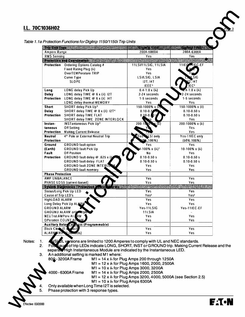
Table 1 . 1 a Protection Functions for Digitrip 1150/1 150i Trip Units
Protection Ordering Options Catalog# 11LSI/11LSIG, 11LSIA Fixed Rating Plug {In) Yes OverTEMPerature TRIP Yes Curve Type LSI/LSIG, LSIA
SLOPE l2T, 14T IEEES
Long LONG delay Pick Up 0.4-1.0 X (/n) Delay LONG delay TIME@ 6 x (/r) 12T 2-24 seconds Protection LONG delay TIME@ 6 x (lr) 14T 1-5 seconds
thermal MEMORY Yes Short SHORT delay Pick Up3 150-1000% X (/r) Delay SHORT delay TIME @ 8 x (/r) 12P 0.10-0.50 s Protection SHORT delay TIME FLAT 0.10-0.50 s
SHORT dela TIME ZONE INTE R CK Yes lnstan- INSTantaneous Pick Up3 200-1000% X (In) taneous Off Setting Yes Protection Ma Current Release Neutral 4'h Pole or External Neutral Trip ly Protection Ground GROUND fault option Yes (Earth) GROUND fault Pick Up 24-100% X {In)' Fault Off Position No Protection GROUND fault delay@ .625 x (In) 12T 0.10-0.50 s
GROUND fault delay FLAT 0.10-0.50 s GROUND fault ZONE INTE RLOCK Yes
UNO Yes
Yes
ick Up LED Cause of LED's Yes2 HighLOAD ALARM Yes Long Delay Pick Up ALARM Yes GROUND ALARM Yes-11LSIG
11LSIA Yes Yes
Yes Yes
111EC/111EC-EF Yes Yes
LSI/LSIG 12T, 14T
IEC5 0.4-1.0 x (In)
2-24 seconds 1-5 seconds
y 150-1000% X (/r)
0.10-0.50 s 0.10-0.50 s
Yes 200-1000% X (In)
Yes 10-100% X {In)
Yes 0.10-0.50 s 0.10-0.50 s
Yes y
Yes
Yesz Yes Yes
Yes-111EC-EF
Yes Yes
Yes Yes
Notes: 1. ANSI/UL versions are l imited to 1200 Amperes to comply with UL and NEC standards.
Page 3
2. Four cause of trip LEOs indicate LONG, SHORT, INST or G ROUND trip. Making Current Release and the separate High Instantaneous Module are indicated by the Instantaneous LED.
3 . A n additional setting is marked M 1 where: 800 - 3200A Frame M1 = 14 x In for Plug Amps 200 through 1250A
M1 = 12 x In for Plug Amps 1600, 2000, 2500A M1 = 10 x In for Plug Amps 3000, 3200A
4000 -6300A Frame M1 = 14 x In for Plug Amps 2000, 2500A M1 = 12 x In for Plug Amps 3200, 4000, 5000A (see Section 2.5) M1 = 10 x In for Plug Amps 6300A
4. Only available when Long T ime 12T is selected. 5. Phase protection with 3 response types.
Effective 03/2000 www . El
ectric
alPar
tMan
uals
. com
Page 4
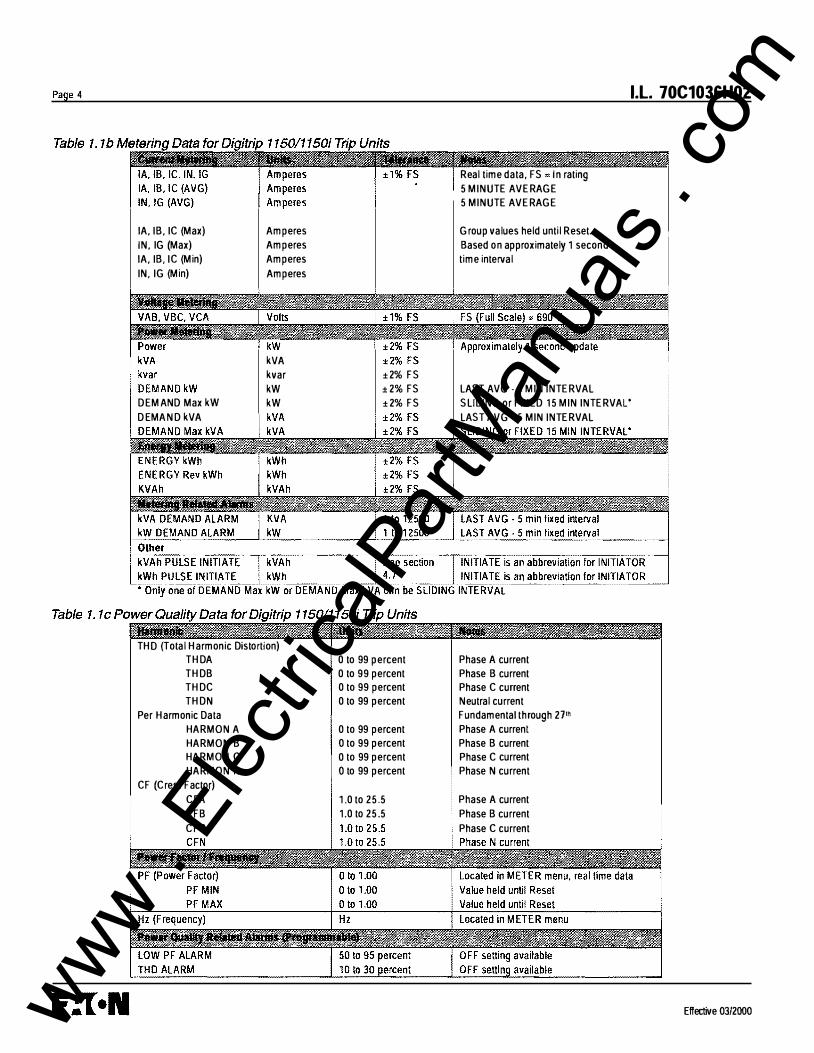
lA, IB, IC (Max) IN, IG (Max) lA, IB, IC (Min) IN,IG (Min)
DEM AND Max kW D EMAND kVA
Amperes Amperes Amperes Amperes
kVA kvar kW kW
THO (Total Harmonic Distortion) THDA THDB THDC THDN
Per Harmonic Data HARMON A HARMON B HARMON C HARMON N
C F (Crest Factor) CFA CFB CFC
±2% FS ±2% FS ±2% FS
0 to 99 percent 0 to 99 percent 0 to 99 percent 0 to 99 percent
0 to 99 percent 0 to 99 percent 0 to 99 percent 0 to 99 percent
1.0 to 25.5 1.0 to 25.5
I.L. 70C1036H02
Real time data, FS In rating 5 MINUTE AVERAGE 5 MINUTE AVERAGE
Group values held until Reset. Based on approximately 1 second time interval
LAST AVG · 5 MIN INTERVAL SLIDING or FIXED 15 MIN INTERVAL' LAST AVG- 5 MIN INTERVAL
Phase A current Phase B current Phase C current Neutral current Fundamental through 271h Phase A current Phase B current Phase C current Phase N current
Phase A current Phase B current Phase C current
Effective 03/2000 www . El
ectric
alPar
tMan
uals
. com
I .L. 70C1036H02
If you have any questions or need further information or instructions, please contact your local representative or the Customer Support Center at 1-800-356-1234.
1.0 GENERAL DESCRIPTION OF DIGITRIP TRIP UNITS
The Digitrip Trip Units are breaker subsystems that provide the protective functions of a circuit breaker. The trip unit is in a removable sealed housing, installed in the breaker, and can be replaced in the field by the end user.
This instruction book specifically covers the application of Digitrip Trip Units, as illustrated in Figure 1.1, installed in Magnum and Magnum DS Breakers. Throughout this Instructional Leaflet, the use of the term "Magnum Breakers" refers to both the Magnum and Magnum DS lowvoltage, AC power circuit breakers.
The Magnum Digitrip line of trip units consists of the 1150 which conforms to UL standards, and model 1150i conforming to IEC standards. Throughout this Instructional Leaflet, the use of the term Digitrip 1150 trip units refers to both models unless otherwise stated. There are three possible styles of the DT 1150 (11 LSI, 11 LSIG, 11 LSIA) and two styles of the DT 1150i (111EC and 111EC-EF).
The Digitrip 1150 trip units may be applied to either 50 or 60 Hz systems.
Digitrip DT1150 family of trip units incorporate two microprocessors in their design. One processor is devoted totally to the task of current protection functions. This processor provides true RMS current sensing for the proper coordination with the thermal characteristics of conductors and equipment. T he Digitrip analyzes the secondary current signals from the circuit breaker current sensors and, when preset current levels and time delay settings are exceeded, sends an initiating trip signal to the Trip Actuator of the circuit breaker. The current sensors provide operating power to the trip unit. As current begins to flow through the breaker, the sensors generate a secondary current which powers the trip unit.
The second microprocessor provides the display, communications, metering, harmonic calculations, alarming and auxiliary relay functions. These additional features require that auxiliary power be provided to the circuit breaker.
1.1 Protection
Each Digitrip DT1150 Trip Unit is completely self-contained and requires no external control power to operate its basic over current protection functions. It operates from current signal levels derived through current sensors mounted in the circuit breaker. The types of protection available for each model are shown in Table 1.1 .
Effective 03/ZOOO
Page 5
The Digitrip 1150 family of trip units provides five phase and two ground (time-current) curve-shaping adjustments. To satisfy the protection needs of any specific installation, the exact selection of the available protection function is adjustable. The short delay and ground fault adjustments include either a FLAT or 12T response. A pictorial representation of the applicable time-current curves for the selected protection functions is provided, for user reference, on the face of the trip unit as shown in Figure 1.1.
NOTE: The Digitrip 1150 (11 LSI style) and Digitrip 1150i (111EC) are the two styles that can be used on 3-pole or 4-pole circuit breakers for the protection of the neutral circuit. For a 3-pole breaker an external sensor of the same rating as the phase sensor needs wired to the circuit breaker. Only these two styles can provide neutral protection, although all styles can provide neutral metering and alarming (one exception is that there is no metering for source or zero sequence Ground Fault application). These styles also have a protection setting called Neutral Ratio. The 1 00% setting is the default and is used when phase and neutral conductors are of the same ampacity. The 50% setting is for a half sized neutral conductor and essentually shifts the Long Time thermal curve to the left making it more sensitive. Refer to the National Electric Code (N EC) for the appropriate application for 4-pole breakers.
1.2 Mode of Trip and Status Information
On all DT1150 units, a green light emitting diode (LED), labeled Status, blinks approximately once each second to indicate that the trip unit is operating normally. This Status LED will blink at a faster rate if the Digitrip is in a pick-up, or overload, mode.
Red LEOs on the face of the 1150 family of trip units flash to indicate the cause, or trip mode, for an automatic trip operation (for example, ground fault, overload, or short circuit trip). A battery in the Digitrip unit maintains the trip indication until the Reset button is pushed. The battery is satisfactory if its LED lights green when the Battery Test button is pushed (see Section 6).
NOTE: The Digitrip 1150 family provides all protection functions regardless of the status of the battery. The battery is only needed to maintain the automatic trip indication when auxiliary power is not available.
1.3 Installation and Removal
1.3 .1 Installation of the Trip Unit
Align the Digitrip unit with the molded guide ears on the platform and spring clips of the Magnum Circuit Breaker. Before plugging into the black edge connector, align the
www . El
ectric
alPar
tMan
uals
. com

Page 6
Display WindO'Ii
Connector J5 Connector K4 (3 Point)
111 0<1111"7�+-+- Connector K 1 (9 Point)
I .L. 70C1036H02
Figure 1.2 Installation of the Digitrip Unit into a Magnum Breaker (Side View)
long pins on the bottom of the Digitrip into the white, 1 1 , connector. See Figure 1 . 2. Press the unit into breaker until the PC board edge engages into the connector and the spring clips engage over the Digitrip's housing.
1.3.2 Rating Plug Installation
A wARNING
DO NOT ENERGIZE THE MAGNUM BREAKER WITH THE DIGITRIP REMOVED OR DISCONNECTED FROM ITS CONNECTOR.DAMAGE TO INTERNAL CURRENT
TRANSFORMERS MAY OCCUR DUE TO AN OPEN CIRCUIT CONDITION.
IF A RATING PLUG IS NOT INSTALLED IN THE TRIP UNIT, THE UNIT W ILL INITIATE A TRIP WHEN IT IS ENERGIZED.IN ADDI"riON THE INSTANTANEOUS LED WILL LIGHT ON A PLUG TRIP.
Insert the rating plug into the cavity on the right-hand side of the trip unit. Align the three pins on the plug with the sockets in the cavity. The plug should fit with a slight insertion force.
Effective 03/2000 www . El
ectric
alPar
tMan
uals
. com
I.L. 70C1036H02
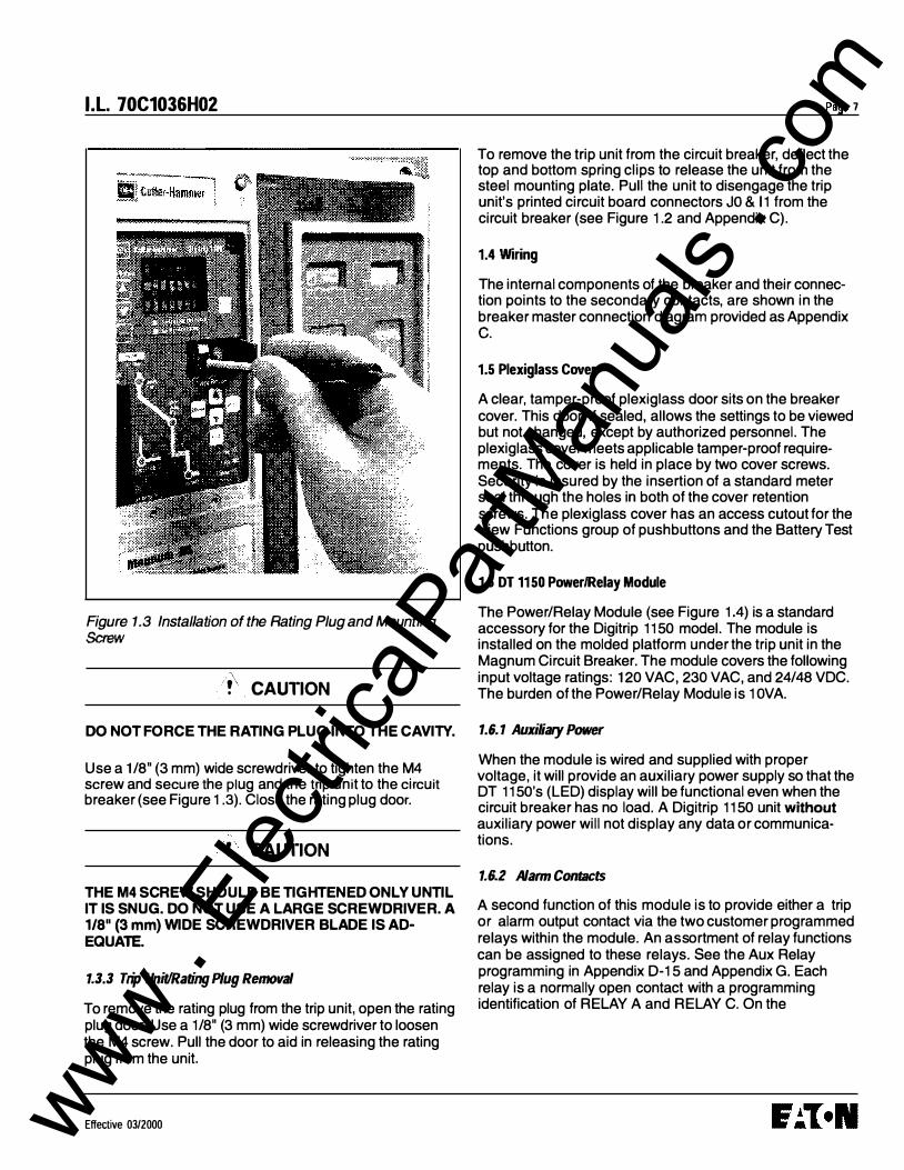
Figure 1.3 Installation of the Rating Plug and Mounting Screw
/(.CAUTION DO NOT FORCE THE RATING PLUG INTO THE CAVITY.
Use a 1/8" (3 mm) wide screwdriver to tighten the M4 screw and secure the plug and the trip unit to the circuit breaker (see Figure 1.3). Close the rating plug door.
!. CAUTION THE M4 SCREW SHOULD BE TIGHTENED ONLY UNTIL IT IS SNUG. DO NOT USE A LARGE SCREWDRIVER. A 1/8" (3 mm) WIDE SCREWDRIVER BLADE IS ADEQUATE.
1.3.3 Trip Unit/Rating Plug Removal
To remove the rating plug from the trip unit, open the rating plug door. Use a 1/8" (3 mm) wide screwdriver to loosen the M4 screw. Pull the door to aid in releasing the rating plug from the unit
E ffective 03/2000
Page 7
To remove the trip unit from the circuit breaker, deflect the top and bottom spring clips to release the unit from the steel mounting plate. Pull the unit to disengage the trip unit's printed circuit board connectors JO & 11 from the circuit breaker (see Figure 1.2 and Appendix C).
1.4 Wiring
The internal components of the breaker and their connection points to the secondary contacts, are shown in the breaker master connection diagram provided as Appendix c.
1.5 Plexiglass Cover
A clear, tamper-proof plexiglass door sits on the breaker cover. This door, if sealed, allows the settings to be viewed but not changed, except by authorized personnel. The plexiglass cover meets applicable tamper-proof requirements. The cover is held in place by two cover screws. Security is insured by the insertion of a standard meter seal through the holes in both of the cover retention screws. The plexiglass cover has an access cutout for the View Functions group of pushbuttons and the Battery Test pushbutton.
1.6 DT 1150 Power/Relay Module
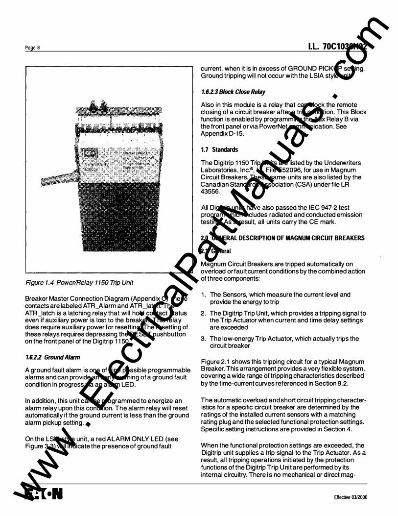
The Power/Relay Module (see Figure 1.4) is a standard accessory for the Digitrip 1150 model. The module is installed on the molded platform under the trip unit in the Magnum Circuit Breaker. The module covers the following input voltage ratings: 120 VAC, 230 VAC, and 24/48 VDC. The burden of the Power/Relay Module is 1 OVA.
1.6.1 Auxiliary Power When the module is wired and supplied with proper voltage, it will provide an auxiliary power supply so that the DT 1150's (LED) display will be functional even when the circuit breaker has no load. A Digitrip 1150 unit without auxiliary power will not display any data or communications.
1.6.2 Alarm Contacts
A second function of this module is to provide either a trip or alarm output contact via the two customer programmed relays within the module. An assortment of relay functions can be assigned to these relays. See the Aux Relay programming in Appendix D-15 and Appendix G. Each relay is a normally open contact with a programming identification of RELAY A and RELAY C. On the
www . El
ectric
alPar
tMan
uals
. com
Page 8
Figure 1.4 Power/Relay 1150 Trip Unit
Breaker Master Connection Diagram (Appendix C) these contacts are labeled ATR_Aiarm and ATR_Iatch. The ATR_Iatch is a latching relay that will hold contact status even if auxiliary power is lost to the breaker. This relay does require auxiliary power for resetting. The resetting of these relays requires depressing the R ESET pushbutton on the front panel of the Digitrip 1 1 50.
1.6.2.2 Ground Alarm A ground fault alarm is one of nine possible programmable alarms and can provide an early warning of a ground fault condition in progress via an alarm LED.
In addition, this unit can be programmed to energ ize an alarm relay upon this condition. The alarm relay will reset automatically if the ground current is less than the ground alarm pickup setting.
On the LSIA style unit, a red ALARM ONLY LED (see Figure 3.3) will indicate the presence of ground fault
l.l. 70C1036H02
current, when it is in excess of GROUND PICKUP setting. Ground tripping will not occur with the LSIA style unit.
1.6.2.3 Block Close Relay
Also in this module is a relay that can block the remote closing of a circuit breaker after a trip condition. This Block function is enabled by programming the Aux Relay B via the front panel or via PowerNet communication. See Appendix D-1 5.
1. 7 Standards
The Digitrip 1 1 50 Trip Units are listed by the Underwriters Laboratories, Inc.®, UL File E52096, for use in Magnum Circuit Breakers. These same units are also listed by the Canadian Standards Association (CSA) under file LR 43556.
All Digitrip un its have also passed the IEC 947-2 test program which includes radiated and conducted emission testing. As a result, all units carry the CE mark.
2.0 GENERAL DESCRIPTION OF MAGNUM CIRCUIT BREAKERS
2.1 General
Magnum Circuit Breakers are tripped automatically on overload or fault current conditions by the combined action of three components:
1 . The Sensors, which measure the current level and provide the energy to trip
2. The Digitrip Trip Unit, which provides a tripping signal to the Trip Actuator when current and time delay settings are exceeded
3. The low-energy Trip Actuator, which actually trips the circuit breaker
Figure 2 . 1 shows this tripping circuit for a typical Magnum Breaker. This arrangement provides a very flexible system, covering a wide range of tripping characteristics described by the time-current curves referenced in Section 9.2.
The automatic overload and short circuit tripping characteristics for a specific circuit breaker are determined by the ratings of the installed current sensors with a matching rating plug and the selected functional protection settings. Specific sett ing instructions are provided in Section 4.
When the functional protection settings are exceeded, the Digitrip unit supplies a trip signal to the Trip Actuator. As a result, all tripping operations initiated by the protection functions of the Digitrip Trip U nit are performed by its internal circuitry. There i s no mechanical or direct mag-
Effective 03/2000 www . El
ectric
alPar
tMan
uals
. com

I.L. 70C1036H02
netic action between the primary current and the mechanical tripping parts of the breaker, thus external control power is not required for overload or fault current tripping.
A wARNING
IMPROPER POLARITY CONNECTIONS ON THE TRIP ACTUATOR COIL WILL DEFEAT THE OVERLOAD AND SHORT CIRCUIT PROTECTION, WHICH COULD RESULT IN PERSONAL INJURY.
OBSERVE POLARITY MARKINGS ON THE TRIP ACTUATOR LEADS AND CONNECT THEM PROPERLY USING ·rHE INSTRUCTIONS PROVIDED.
2.2 low-Energy Trip Actuator
The mechanical force required to initiate the tripping action of a Magnum Circuit Breaker is provided by a special lowenergy Trip Actuator. The Trip Actuator is located under the black molded platform on which the Digitrip unit is supported. The Trip Actuator contains a permanent magnet assembly, moving and stationary core assemblies, a spring and a coil. Nominal coil resistance is 25 ohms and the black lead is positive. The circuit breaker mechanism assembly contains a mechanism-actuated reset lever and
Top End
a trip lever to actuate the tripping action of the circuit breaker.
Page 9
When the Trip Actuator is reset by the operating mechanism, the moving core assembly is held in readiness against the force of the compressed spring by the permanent magnet. When a tripping action is initiated, the lowenergy Trip Actuator coil receives a tripping pulse from the Digitrip unit. This pulse overcomes the holding effect of the permanent magnet, and the moving core is released to trigger the tripping operation via the trip lever.
2.3 Ground Fault Protection
Only the Digitrip 1150 cat# 11 LSIG and Digitrip 1150i cat# 111EC-EF provide ground fault protection.
2.3.1 General
When the Digitrip 1150 family includes ground fault protection features, the distribution system characteristics (for example, system grounding, number of sources, number and location of ground points, and the like) must be considered along with the manner and location in which
� ���--- , I I I I I I I I
,-.... /11\ .. �--···�--� · ··· 0 �--<
I Polarity I Marks I I I I I I I I I I I
Bottom End
Figure 2. 1 Tripping Circuit for a Typical Magnum Breaker (Partial)
Effective 0312000
' I � I : Digitrip I I I I I I I I I _I
www . El
ectric
alPar
tMan
uals
. com

Page 10
the circuit breaker is applied to the system. These elements are discussed in Sections 2.3.3 through 2 .3.6.
The Digitrip 1 1 50 family uses three modes of sensing to detect ground fault currents: residual, source ground, and zero sequence (see Table 2.1 ). The breaker secondary contact i nputs B-6 and B-7 are used to configure the trip unit. A jumper from B-6 to B-7 programs the trip unit for either a source ground or zero sequence configuration. Removing the jumper will program the unit for a residual ground fault scheme. This j umper resides on the stationary side of the switchgear assembly. In all three schemes, the proper current sensor input is required on the external sensor input terminals B-4, B-5 of the breaker secondary contacts.
Table 2. 1 Digitrip Sensing Modes
Ground (Earth) Breaker Digitrip Gf I Faul Secondary Applicable Figure Sensing •
Sensing Melhod Contacts Req'd Breakers Reference Element Used
i Residual No Jumper 3 or 4 pole 2.2, 2.3, 2.5. 2.9 element R5
Source Ground Jumper B6 to B7 3 pole only 2.7 element R4 i
Zero Sequence Jumper 86 to B7 3 pole only 2.8 element R4
Note• Th1s mtormalion applies to Trip Umts with Ground
2.3.2 Residual Sensing
Residual Sensing is the standard mode of ground fault sensing in Magnum Circuit Breakers. This mode utilizes one current sensor on each phase conductor and one on the neutral for a 4-wire system (shown in Figures 2.2 and 2.3). If the system neutral is grounded, and no phase to neutral loads are used, the Digitrip 1 1 50 with ground includes all of the components necessary for ground fault protection. This mode of sensing vectorially sums the outputs of the three or four individual current sensors. For separately-mounted neutrals, as long as the vectorial sum is zero, then no ground fault exists. The neutral sensor must have characteristics and a ratio which matches the three internally-mounted phase current sensors. Available types of neutral sensors are shown in Figure 2.4. Residual ground fault sensing features are adaptable to main and feeder breaker applications.
'
I!\ CAUTION
IF THE SENSOR CONNECTIONS ARE INCORRECT, A NUISANCE TRIP MAY OCCUR. ALWAYS OBSERVE THE POLARITY MARKINGS ON THE INSTALLATION DRAWINGS. TO INSURE CORRECT GROUND FAULT EQUIP-
I.L. 70C1036H02
MENT PERFORMANCE, CONDUCT FIELD TESTS TO COMPLY WITH NEC REQUIREMENTS UNDER ARTICLE 230-95(C).
2.3.3 Source Ground Sensing
Depending upon the installation requirements, alternate ground fault sensing schemes may be dictated (see Figures 2.6 and 2.7). The ground return method is usually applied when ground fault protection is desi red only on the main circuit breaker in a simple radial system. This method is also applicable to double-ended systems where a midpoint grounding electrode is employed. For this mode of sensing, a single current sensor mounted on the equipment-bonding jumper directly measures the total ground current flowing in the grounding electrode conductor and all other equipment-grounding conductors.
In the CURRENT (protection) submenu, there is a setting (EXT GND CT RATIO) that enables the presentation of ground pickup in amperes and the display of ground current in amperes when an External Ground CT is employed. This screen is presented when j umper B-6 to B-7 is present on a trip unit equipped with G ROUND. External Ground CT ratios of 1 0, 1 00, 200, 400, 800, 1 000 A:1 and "none" settings are selectable, with "none" defaulting to the plug (In) rating. With the correct ratio selected the GF pickup settings are adjustable in amperes.
2.3.4 Zero Sequence Sensing
Zero Sequence Sensing, also referred to as vectorial summation (see Figure 2 .8), is applicable to mains, feeders, and special schemes involving zone protection . Zero Sequence current transformers (4 1 /2" x 1 3 1 /2" [1 1 4 mm x 342 mm] rectangular inside dimensions) are available with 1 00:1 and 1 000: 1 ratios. The EXT GND CT RATIO setting described above is applicable for zero sequence.
2.3.5 Multiple Source/Multiple Ground
A Multiple Source/Multiple Ground scheme is shown in Figure 2.9. In this figure, a ground fault is s hown which has two possible return paths, via the neutral , back to its source. The three neutral sensors are interconnected to sense and detect both ground fault and neutral currents.
Call Cutler-Hammer for more details on this scheme.
Effective 03/2000 www . El
ectric
alPar
tMan
uals
. com
I.L. 70C1036H02
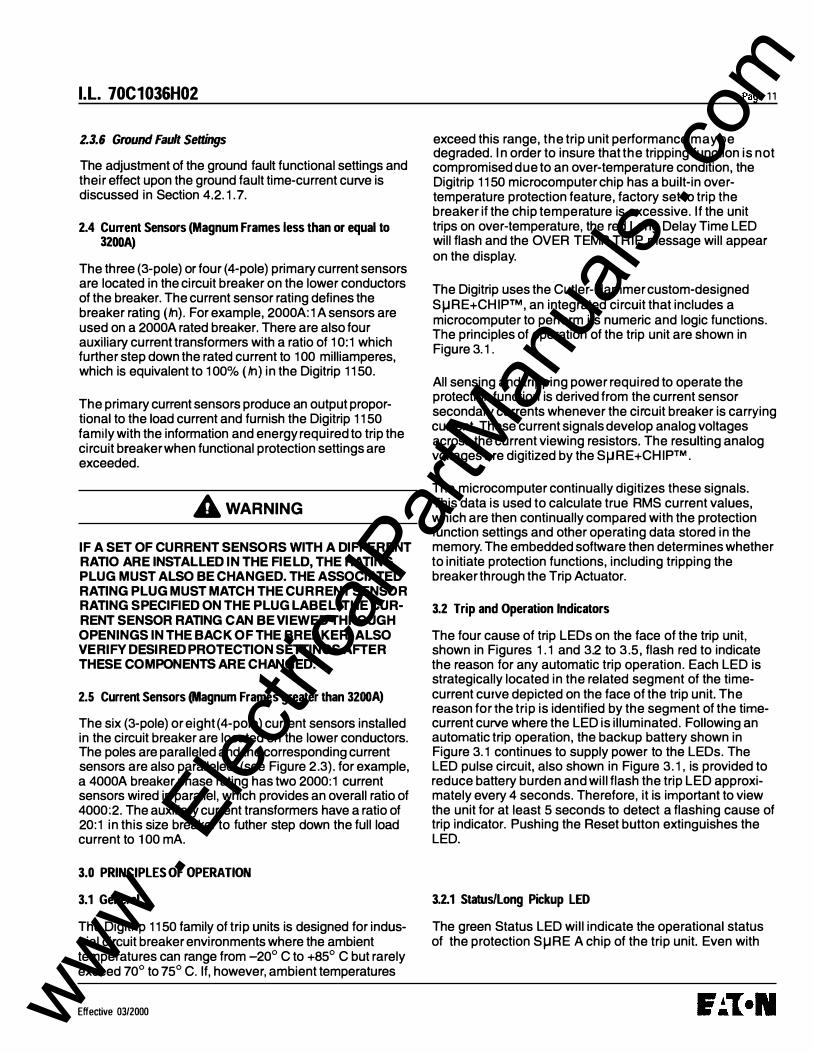
2.3.6 Ground Fault Settings
The adjustment of the ground fault functional settings and their effect upon the ground fault time-current curve is discussed in Section 4.2. 1. 7.
2.4 Current Sensors (Magnum Frames less than or equal to 3200A)
The three (3-pole) or four (4-pole) primary current sensors are located in the circuit breaker on the lower conductors of the breaker. The current sensor rating defines the breaker rating (In). For example, 2000A: 1A sensors are used on a 2000A rated breaker. There are also four auxiliary current transformers with a ratio of 1 0:1 which further step down the rated current to 1 00 milliamperes, which is equivalent to 100% (In) in the Digitrip 1150.
The primary current sensors produce an output proportional to the load current and furnish the Digitrip 1150 family with the information and energy required to trip the circuit breaker when functional protection settings are exceeded.
A wARNING
IF A SET OF CURRENT SENSORS WITH A DIFFERENT RATIO ARE INSTALLED IN THE FIELD, THE RATING PLUG MUST ALSO BE CHA NGED. THE A SSOCIATED RATING PLUG MUST MATCH THE CURRENT SENSOR RATING SPECIFIED ON THE PLUG LABEL. THE CURRENT SENSOR RATING CAN BE VIEWED THROUGH OPENINGS IN THE BACK OF THE BREAKER. ALSO VERIFY DESIRED PROTECTION SETTINGS AFTER THESE COMPONENTS ARE CHANGED.
2.5 Current Sensors (Magnum Frames greater than 3200A)
The six (3-pole) or eight (4-pole) current sensors installed in the circuit breaker are located on the lower conductors. The poles are paralleled and the corresponding current sensors are also paralleled (see Figure 2.3). for example, a 4000A breaker phase rating has two 2000:1 current sensors wired in parallel, which provides an overall ratio of 4000:2. The auxiliary current transformers have a ratio of 20:1 in this size breaker to futher step down the full load current to 100 mA.
3.0 PRINCIPLES OF OPERATION
3.1 General
The Digitrip 1150 family of trip units is designed for industrial circuit breaker environments where the ambient temperatures can range from -20° C to +85° C but rarely exceed 70° to 75° C. If, however, ambient temperatures
Effective 03/2000
Page 11
exceed this range, the trip unit performance may be degraded. In order to insure that the tripping function is not compromised due to an over-temperature condition, the Digitrip 1150 microcomputer chip has a built-in overtemperature protection feature, factory set to trip the breaker it the chip temperature is excessive. If the unit trips on over-temperature, the red Long Delay Time LED will flash and the OVER TEMP TRIP message will appear on the display.
The Digitrip uses the Cutler-Hammer custom-designed S�RE+CHIP™, an integrated circuit that includes a microcomputer to perform its numeric and logic functions. The principles of operation of the trip unit are shown in Figure 3. 1.
All sensing and tripping power required to operate the protection function is derived from the current sensor secondary currents whenever the circuit breaker is carrying current. These current signals develop analog voltages across the current viewing resistors. The resulting analog voltages are digitized by the S�RE+CHIP™.
The microcomputer continually digitizes these signals. This data is used to calculate true RMS current values, which are then continually compared with the protection function settings and other operating data stored in the memory. The embedded software then determines whether to initiate protection functions, including tripping the breaker through the Trip Actuator.
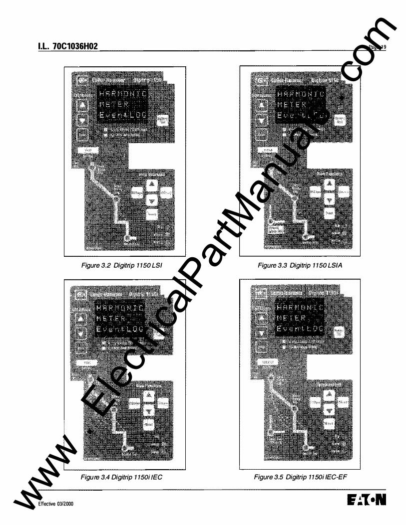
3.2 Trip and Operation Indicators
The four cause of trip LEOs on the face of the trip unit, shown in Figures 1. 1 and 3.2 to 3.5, flash red to indicate the reason for any automatic trip operation. Each LED is strategically located in the related segment of the timecurrent curve depicted on the face of the trip unit. The reason for the trip is identified by the segment of the timecurrent curve where the LED is illuminated. Following an automatic trip operation, the backup battery shown in Figure 3. 1 continues to supply power to the LEOs. The LED pulse circuit, also shown in Figure 3. 1, is provided to reduce battery burden and will flash the trip LED approximately every 4 seconds. Therefore, it is important to view the unit tor at least 5 seconds to detect a flashing cause of trip indicator. Pushing the Reset button extinguishes the LED.
3.2.1 Status/Long Pickup LED
The green Status LED will indicate the operational status of the protection S�RE A chip of the trip unit. Even with
www . El
ectric
alPar
tMan
uals
. com

Page 1 2
no external power present, i f the load current through the circuit breaker exceeds approximately 1 2 percent (3 phase power) of the current sensor rating, the LED will flash on and off once each second indicating that the trip unit is energized and operating properly. (See Figure 3.1 )
In an overload (Long Pickup) condition this status LED flashes at approximately 4 times per second while the overload persists.
3.2.2 Alarm LED
In addition to the green status LED, a yellow alarm LED is provided to i ndicate real time alarm conditions existing on the power system. See Appendix D-1 6 for the programing of these alarms. Also, if an unusual condition is detected within the Digitrip's hardwire or firmware, this LED will l ight along with an ALARM message.
3.2.3 Trip LED
The trip LED is i l luminated upon any trip condition. It is also a real time display and incorporates the breaker's auxiliary switch input for its logic. Pushing the Reset pushbutton or closing the breaker wi ll clear this LED.
3.3 Making Current Release
All Digitrip 1 1 50 Trip Units have a Making Current Release function. This safety feature prevents the circuit breaker from being closed and latched-in on a faulted circuit. This is a nonadjustable sensing circuit. It is preset to trip at an instantaneous current numerically equivalent to 25 x ( /n). (Note that currents of -1 1 x (In) with maximum asymmetry also reach this threshold.)
The Making Current Release is enabled only for the first two cycles following an initial circuit breaker closing operation. The Making Current Release will trip the circuit breaker instantaneously and flash the Instantaneous LED as well as indicating "Making Current Trip" on the display panel.
3.4 Zone lnter1ocking
;!' CAUTION
IF ZONE INTERLOCKING IS NOT TO BE USED AND ONLY STANDARD TIME-DELAY COORDINATION IS INTENDED), JUMPER TERMINAL BS TO B9 ON THE BREAKER SECONDARY CONNECTOR.
Zone Selective Interlocking (or Zone Interlocking) is available on the Digitrip 1 1 50 for the Short Delay and
I .L. 70C1 036H02
G round Fault protection functions (see Figure 3.1 ). The zone interlocking signal is wired via a single set of wires labeled Zone In (Zin) and Zone Out (Zout) along with a Zone Common wire. The Zone Selective Interlocking function combines the interlocking of Short Delay and Ground Fault. A zone out signal is issued if the ground fault pickup is exceeded or if the short delay pickup is exceeded or if the value of 2 x (/r) is exceeded. Zone Selective Interlocking provides the fastest possible tripping for faults within the zone of protection of the breaker and yet also provides positive coordination among all b reakers in the system (mains, ties, feeders, and downstream breakers) to limit a power outage to only the affected parts of the system. When Zone Interlocking is employed, a fault within the zone of protection of the breaker will cause the Digitrip 1 1 50 to:
• Trip the affected breaker immediately and, at the same time,
• Issue a signal to upstream Digitrip units to restrain from tripping immediately. The restraining signal causes the upstream breakers to follow their set coordination times, so that the service is only locally disrupted while the fault is cleared i n the shortest time possible.
For an example of how Zone Selective I nterlocking may be used , see Appendix A of this Instructional Leaflet.
3.5 PT Module
The PT Module is i nternally wired in the breaker to the l ine side breaker terminals. It provides signal data to calculate voltage, power, energy and related data. The PT module is a three phase, three wire input and three wire output step down transformer with a wye to wye hookup.
/!\ CAUTION
A DIELECTRIC DISCONNECT PLUG LOCATED ON THE LEFT SIDE OF THE BREAKER IS PROVIDED WITH THIS MODULE AND IS TO BE REMOVED WHEN DIELECTRIC T ESTING OF THE BREAKER IS CONDUCTED. FAILURE TO REMOVE PLUG WHEN TESTING CAN RESULT IN DAMAGE TO TRIP UNIT AND PT MODULE.
Effective 03/2000 www . El
ectric
alPar
tMan
uals
. com

I .L. 70C1036H02
Source L, L,
t,
Load
Notes: G) In this scheme, all breaker secondary currents (at !he 100 rnA level) are summed together at the
pc board donut transformer to sense grouna fault v1a element R5. ® No Jumper on secondary contacts B-6, B-7. (j) Neutral input (if 4-wlre) Is via contacts B-4, 6-5. Neutral current 1nput to secondary contacts Is tA,
equivalent to 1 per unit ground.
I '
--'
Figure 2.2 3-Pole, 4-Wire Breaker with Neutral Sensor Connections for 3200A Frame Using Residual GF Sensing
Source l"1 LNl LA. La· lc1 ln lel Lo ®
2000:1
Notes:
it,-t, ttt, t, ·�_L_-<��
2000:1 Load
<DIn this scheme, all breaker secondary currents (at the 100 mA level) are summed together at the PC board donut transformer to sense ground fault via element R5.
®In this scheme, the current sensors In the breaker poles are parallel-wired to achieve a 4000 amp breaker ratmg. Other available ratings in this double-wide configuration are 6300A, SOOOA, 3200A, 2500A, and 2000A.
®Shown is ABCABC bus configuration.
Figure 2.3 Neutral Sensor Connections for 4000A Frame Using Residual Ground Fault Sensing
Effective 03/2000
Page 13
www . El
ectric
alPar
tMan
uals
. com

Page 1 4
ALL SEC!JUt.IDARV CURRE.NTS 100 A�P NOI'-\!NAL AT FULL �CAL.[
1NSV\AT10"4 LEVEt.. Q.6 KV, B!L �V f�..ol\ WQ,V�
CONTINGUS Tl-iE�NAL Cl;RRENT FACTOR 1.33 3C.° C. O.MI:; .
Figure 2.4 Digitrip Neutral Sensor Types
SoU'C& L, l, L, lc
: �t-t��t� 1 <���-- -----�····�� r* -�<�-tr�.f�
10:1 AUX. CT
load
Noles: (j) In th1s scheme, all breaker secondary currents (at 1he 100 mA level) ere summed together at the PC board
donut transfonner11:> serse ground fautt via element R5.
@ Do not jumper secondary rontacts fH!, B-7. Thia will defeat au ground tauH protection in application lor 4 pole breaker.
® Ground fault style trip und is install!l(l.
Figure 2.5 4-Pole-3200A Frame Using Residual Ground Fault (Earth-Fault) Sensing
I.L. 70C1036H02
Effective 03/2000 www . El
ectric
alPar
tMan
uals
. com

I.L. 70C1036H02
Source
L,
t, « 1 R/1 *-<
® �<1-§-�?t----··········�-----��------- ···········�-�----��1 '-<' 8-6
B-5
Notes:
Load Ground Retum Electrode Conductor
ryp1cal Appl ication - Main
G) lr'l this S<:heme, the residua l sensing element R5 is not used. The ground current is d1rect true gr ound current and Is sensed directly via element R4.
<Z1 A ju rnoer js required on B-6, B-7 (secondary contacls) lo prograrn Uoe Digilrip 1150 Ia use element R4 and input on B-4. B-5 directly for source ground sensing.
@ Thla scheme i• not applicabl• to 4-pole break.,., No secondary contacts (B..ol and B-5) are available on 4-pole breakers. Do not jumper B-6, B-7 In 4-pote applications.
Figure 2.6 Source Ground Fault Sensing Scheme for 3200A Frame
<
Digllrip wilhGF
R,
R,
G) @ tn'"�---t----�--�--�------------�'"'':�----<<1��
9
� Load Ground Return Electrode Conductor
Notes:
20:1 AUX.
CD In this sd"ieme. the current S911SOr& in the breaker poles are parallel-wired to achieve a 4000 Amp breaker rating . The ground fault is sensed directly via element R4•
� A jumoor ,s �l!:!N on B-6, B-7 secondary contacts to program the Digilrip 1150 to use element R4 directly lor source ground sensing. If the b reaker is removed from cell (B·S, 8·7). jumper disconnected, Residual Ground setting will apply.
® Source ground sensor input is via B-4, B-5. Source ground current input to secondary contacts is 2A, equivalent to 1 per unit ground. Two standard lA secondary sensors with primary in series and seco ndaries para llel may be used.
(j) The scheme is not applicable to 4--pole br&akars. No secondaty contacts (B-4 and B-5) are availab•e on 4-pole breakers. Do not jumpor B-6� B-7 in 4-pole applications.
Figure 2. 7 Source Ground Fault Sensing Scheme for 4000A Frame
Effective 03/2000
Page 15
www . El
ectric
alPar
tMan
uals
. com

Page 16
Source
Noms
(j) This scheme uses a large zero sequence CT to magnetica,'y sum the CU'Ten!s and the output is se�sed via element R.4.
(6) A jumper is required on 8-8. B-7 to prograrn the Otgitrip to use element R4, If the breoker is removed from cell (B-6.8-7) jumper disconnected. Residual Ground seHings will apply.
@ The scheme is not applicable to 4-pole breakers
Figure 2.8 Zero Sequence Sensing Scheme for 32DOA Frame
N
, .. L ' 1,12
'
Notes:
N
.. ,',..,_,_1�,., ��� S:n
5
som Wired in a Loop Configuration
Ground Fault
'� Breaker M2trips smce this is the only breaker seeing the IG fault via element R5,
No jumper on B-6, 8-7 terminals all breakers are programmed lor standard Residual Ground Fault protection,
AUX CTs not shown, W lfing needed at system level is shown as a dotted line,
Capital letters represent primary current. Lowercase letters represent secondary current.
The three breakers (M1, M2, and T) must all have the same break er/sensor rating,
Figure 2.9 Multiple Source/Multiple Ground Scheme
I.L. 70C1036H02
Effective 03/2000 www . El
ectric
alPar
tMan
uals
. com

I.L. 70C1036H02
Disconnect Plug
Figure 2. 1 0 PT Module with Dielectric Disconnect Plug
4.0 PROGRAMMINGNIEWING DIGITRIP 1150 via FRONT PANEL
4.1 Main Menu
4.1.0 Power Up Sequence
When the Digitrip 1150/1150i unit is first powered-up, two different display messages are possible. If the Digitrip has been previously commissioned with customer-made settings, the display will alternate between "Cutler-Hammer DT 1150" and "Customer Settings in Use" messages. Following this the display will enter into the main menu. See Appendix D-1.
If Digitrip settings have not been saved previously the trip unit is using the factory default values. On power up, the Digitrip will then display "CHANGE FACTORY SETUP?". This message will stay on the screen until the user presses ESCape or the SELect pushbutton or until an alarm or trip condition is detected.
The ESCape pushbutton action will keep the factory settings and then will enter the main menu. The factory settings are listed in Appendix D-23 and are not valid for most applications. The appropriate settings need to be defined by a qualified application engineer to provide best overall protection and coordination for the power system.
Effective 03/2000
Page 17
A SELect pushbutton action will provide direct entry into PROGRAM SETTING menu. The first item presented is the Current CUR VE type. LSIG or IEEE or (IEC) current curve types are possible selections depending on trip unit style. Pressing SELect again will select the curve presented in the window center and then step into the individual elements that need programmed. The VIEW up and down arrow selects the function while the EDIT up and down arrow changes value. After they are set they need to be saved by depressing the SAVE pushbutton. The saving will place the customer settings in use. Verify the new settings. See Appendix D-13 for program curve and D-19 for saving and D-5 for view setting menu.
4. 1. 1 Pushbutton Definition
View Functions
The "View Functions" group of push buttons is located in the lower right hand side of the unit and includes the View Up (up arrow), View Down (down arrow), ESCape, SELect, and Reset buttons.
View Up I View Down- View Up and View Down allow the user to scroll through any available menu or submenu in the Digitrip 1150 display.
SELect- The SELect pushbutton selects the submenu for the blinking selection located in the middle of the display.
ESCape- The ESCape pushbutton brings the user up to the previous menu in the display. Multiple ESC pushbutton operation will display Main Menu screen.
Reset- The Reset pushbutton will reset LEOs and screen data. (See Reset Sequence)
Edit Values
The "Edit Values" group located in the upper left hand corner of the Digitrip 1150 unit consists of 3 push buttons: Edit Up (indicated by an up arrow), Edit Down (down arrow) and Save. The Edit Values push buttons are covered by a Plexiglass cover which can be sealed.
Edit Up I Edit Down- Edit Up and Edit Down allow the user to scroll up or down, respectively, through available setting values while in any Program Settings submenu.
Save- The Save pushbutton allows the user to save a group of selected programmable settings from any submenu in the PGM SET menu. Save is also used in the TEST Menu. When prompted, pressing Save will begin the selected test.
www . El
ectric
alPar
tMan
uals
. com

Ill . .... � iii
i I
� c:: � !A .....
tl !Q' � ..... .... � !!! � tl iii' (Q iil 3 ! ::::r OJ � Ill � .... s(i) ht �
(Line/Upper) N A 8 C
���� POW E A/RELAY
Module
cr Current Sensors 311 I I I
y y y y (load/lower)
II
1 Residual Ground
Detection
AUX CTs
Typical Phase and___..-Y' Ground Sensing Resistors
lnte rna! Power Sup ply
m PT Module
Making Current Release Circuitry
(See Section 3.3)
�- � Trip
8�-LRE+CHIP™ A
Protection
+3V Battery �_._____....., 4 bit LED Latch Pulse Chip Circuit
Cause of �Trip LEDs
Zone Interlocks ZtN Zour
Key Pad
Accessory Bus
p::::c= . .. ,.. I n ,-. .-. ,-, ,-, .-, ,-. ,-. ... 0 ·=- ·=· •:J ·=· ·=- •:J ·=·
COM Transceiver
Aux Relay Drivers
;9 ., "' � ""
-. r � (') ..... 0 w en ::c 0 N
www . El
ectric
alPar
tMan
uals
. com
I.L. 70C1036H02 Page 1 9
Figure 3.2 Digitrip 1 150 LSI Figure 3.3 Digitrip 1 150 LSIA
Figure 3.4 Digitrip 1 150i /EC Figure 3.5 Digitrip 1150i IEC-EF
Effective 0312.000 www . El
ectric
alPar
tMan
uals
. com

Page 20
Battery Test
The Battery Test pushbutton is located on the right side of the Digitrip 1 1 50 unit, just above the rating plug door. Battery Test will light the green LED located above the pushbutton to ensure proper voltage in the battery.
4.1.2 Blink mode
Middle Blinking
The middle display, if blinking, indicates that the menu item is selectable or that a submenu exists when a selection brings up another menu with middle text bl inking.
4. 1.3 Programming/Viewing Screens
The View Functions control screen viewing, while Edit Functions apply to programming and storing settings. ALWAYS VERIFY PROGRAMMED SETTINGS B Y ENTERING VIEW SETTINGS AFTER SAVING. All screens are viewable depending on the programmed settings and/or Digitrip 1 1 50 model. I n particular, the METER submenu may be programmed to include anywhere from one to 22 viewable screens when METER is selected, based on the settings chosen in the PGM SEnDISPLAY screens. Similarly, certain screens are only viewable based on availability. For example, in the PGM SEnAuxRLY menu, the selected relay determines the programmable groups displayed. See Appendix D.
Depending on the Digitrip 1 1 50 model, certain menus or screens are not viewable or programmable. When using the LSI factory style unit, viewing and programming menu screens involving Ground or Earth settings are not accessible. When using the LSIG factory style unit, viewing and programming screens involving Neutral Protection are net displayed.
4. 1.4 Reset Pushbutton Operation
4. 1.4. 1 Trip Events
A Reset pushbutton operation does the following after a trip:
a. Clears the cause of trip flashing LEOs (4) after a trip event b. Clears the Trip LED c. Clears Display data
Note: After a Trip Event 1 . Observe any Trip LED flashing on Mimic Curve. 2. Observe message on LED display. 3. Push View Down pushbutton to observe
l .l. 70C1036H02
timestamp of event and view down to observe trip current data. This data, along with timestamp will also be stored in Event Log. 4. After any trip condition , the trip unit should be reset by pressing the Reset Pushbutton. Reclose breaker as desired.
See Appendix D-4 for possible Trip Events and screen data displayed after a trip by using the View Down (down arrow) pushbutton.
4. 1.4.2 Alarm Events
Alarms are tracked in real time and a Reset pushbutton may momentarily clear the alarm but the Alarm LED and Alarm message wil l reappear if condition is sti l l present.
The ESCape pushbutton activation will remove the alarm message from the display and return to normal menu viewing mode, but the yellow alarm LED will remain lit, as the alarm is in the system. See Appendix D-22.
Note: A way to clear an alarm if desired, after reviewing the alarm and its associated data, is to enter the PGM SET Menu followed by the ALARM submenu. The user can then revise or turn off the associated alarm set point value.
See Appendix D-4 for possible Alarm Events and D-22 for multiple Alarm conditions.
4. 1 .4.3 Data resets in Meter screen
A Reset pushbutton operation will reset data values or group of values if the Reset pushbutton is depressed when screen value is displayed. See Appendix D-3 Meter Menu.
4.2 Program Settings PGM SET
4.2.1 Curve Type Selection and Pickupffime Settings
4.2. 1.0 General
Before placing any circuit breaker i n operation , set each trip unit protection setting to the values specified by the engineer responsible for the i nstallation. Each setting is programmed using the front panel pushbuttons and Save when the desi red settings are selected. A few settings are i nterdependent (the LONG PU (lr) rating will indirectly affect the SHORT PU value). Therefore, always verify these settings after programming by entering View Settings Menu.
The installed rating plug must match the current sensors which establish the maximum continuous current rating of
Effective 0312000 www . El
ectric
alPar
tMan
uals
. com
I.L. 70C1036H02
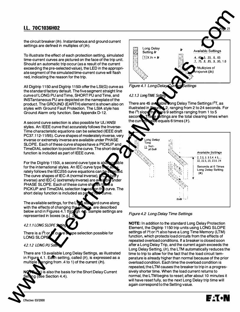
the circuit breaker (In) . Instantaneous and ground current settings are defined in multiples of (In).
To illustrate the effect of each protection setting, simulated time-current curves are pictured on the face of the trip unit Should an automatic trip occur (as a result of the current exceeding the pre-selected value), the LED in the appropriate segment of the simulated time-current curve will flash red, indicating the reason for the trip.
All Digitrip 1 1 50 and Digitrip 1 1 50i offer the LSI(G) curve as the standard factory default The five segment straight line curve of LONG PU and Time, SHORT PU and Time, and INSTantaneous PU are depicted on the nameplate of the product The GROUND (EARTH) element is shown also on styles with Ground Fault Protection. The LSIA style has Ground Alarm only function. See Appendix D-1 2.
A second curve selection is also possible for UUANSI styles. An I EEE curve that accurately follows the InverseTime characteristic equations can be selected (IEEE draft PC37.1 1 2-1 1/95). Curve shapes of moderately inverse, very inverse or extremely inverse are available under PHASE SLOPE. Each of these curve shapes have a PICKU P and TimeDIAL selection to position the curve. The short delay function is included as part of I EEE curve.
For the Digitrip 1 1 50i , a second curve type is also possible for the international styles. An IEC curve type that accurately fol lows the I EC255 curve equations can be selected. The curve shapes of IEC-A (normal inverse), IEC-B (very inverse) and IEC-C (extremely inverse) are available under PHASE SLOPE. Each of these curve shapes have a PICKUP and TimeDIAL selection to position the curve. The short delay function is included as part of I EC curve.
The available settings, for the LSIG standard curve along with the effects of changing the settings, are described below and i n Figures 4.1 through 4.8. Sample settings are represented in boxes (e.g.[]] ) 4.2. 1. 1 LONG SLOPE Setting
There is a 12t or 14-t curve shape selection possible for LONG SLOPE.
4.2. 1.2 LONG PU Setting
There are 1 3 available Long Delay Settings, as illustrated in Figure 4. 1 . Each setting, called (lr) , is expressed as a multiple (ranging from .4 to 1 ) of the current (hl).
NOTE: (/r) is also the basis for the Short Delay Current Setting (see Section 4.4).
Effective 0312000
Long Delay Setting lr rn x /n = lr
lr
Page 21
lr �vailab�_ Settin1!�
.45, .5, .55, .6, .65 .75, .8, .85, .9, .95, 1 .0
Figure 4. 1 Long Delay Current Settings
4.2. 1.3 LongTIME Setting
There are 45 available Long Delay Time Settings 12T, as il lustrated in Figure 4.2, ranging from 2 to 24 seconds. For the 14t slope there are 9 settings ranging from 1 to 5 seconds. These settings are the total clearing times when the current value equals 6 times (lr).
Figure 4.2 Long Delay Time Settings
Seconds at 6 Times Long Delay Setting {lr)
NOTE: I n addition to the standard Long Delay Protection Element, the Digitrip 1 1 50 trip units using LONG SLOPE settings of l2t or 1"1: also have a Long Time Memory (LTM) function, which protects load ci rcuits from the effects of repeated overload conditions. If a breaker i s closed soon after a Long Delay Trip, and the current again exceeds the Long Delay Setting, (lr), the LTM automatically reduces the time to trip to allow for the fact that the load circuit temperature is already higher than normal because of the prior overload condition. Each time the overload condition is repeated, the LTM causes the breaker to trip i n a progressively shorter time. When the load current returns to normal, the LTM begins to reset; after about 1 0 minutes it will have reset ful ly, so the next Long Delay trip time will again correspond to the Setting value.
www . El
ectric
alPar
tMan
uals
. com

Page 22
NOTE: In certain applications, it may be desirable to disable the LTM function by disabling this function in Program Settings.
The action of the L TM must be considered when performing multiple Long Delay Time tests (see Section 5.4) .
4.2. 1.4 SHORT PU Setting
There are 1 9 available Short Delay Current Settings, as illustrated in Figure 4.4. Eighteen settings are in the range from 1 .5 to 1 0 times (k) . (REMEMBER: (k) is the Long Delay Current Setting.) The maximum value M 1 depends on the sensor rating of the circuit breaker and is listed in Note 4 of Table 1 . 1 .
Short De lay Setting 1 .5, 2 , 2 .5 , . . .
9, 9 .5 , 1 0
In M u ltiples of Long D e lay Setting
( /r)
Additional M 1 Valu e is Specified on Ratin g Plug
Figure 4.4 Short Delay Current Settings
4.2. 1.5 SHORT TIME Setting
As illustrated i n Figure 4.5, there are two different Short Delay Slopes: fixed and Ft. The shape selected depends on the type of selective coordination chosen. The l2t response curve will provide a longer time delay for current below 8 x /r than will the FLAT response curve.
Nine FLAT and nine 12t response time delay settings are available. The 12t response is applicable to currents less than 8 times the ampere rating of the installed rating plug (/r) . For currents greater than 8 x (k) the !2t response reverts to the FLAT response.
NOTE: Also see Section 3.4, Zone Interlocking.
4.2. 1.6 INST PU Setting
There are at least 1 8 available Instantaneous Current Settings, as illustrated in Figure 4.6. The value that M1 has depends upon the sensor rating of the circuit b reaker and is specified both on the rating plug label and on the applicable time-current curves referenced in Section 9.2. The Instantaneous Pickup is based on the plug (In) rating.
Short Delay Time
[!Sec.
I.L. 70C1036H02
.1 ' . 1 5 , .2, .25, .3, .35 , .4 , .45, .5
Seconds with FLAT SH ORT SLO PE
121 SLOPE Returns to FLAT Response at Currents H igher than Bx /r -·r .1 . . 1 5 . . 2 . . 25 • . 3 • . 35.
. � 1 .4 , .45, .5 I I I 1 , . Seconds with
<t· ·:··�cp·:::c,,.,..,., .·� 121 SH ORT SLOP E
'l:lW.c.. CC''""""', ' ' 1
Sx lr
I 1 I
I I " -
Figure 4.5 Short Delay Time Settings
, _ _ _ I
> (
/ I_ - - - -"
M1 value is specified on rating plug .
Available Settings
2 , 2 .5 , 3, .. . 9, 9 .5 , 1 0 . . . M 1 ,0 FF
In M u ltiples of Rating P lug A m pe res (In)
Figure 4. 6 Instantaneous Current Settings
Effective 03/2000 www . El
ectric
alPar
tMan
uals
. com

I.L. 70C1036H02
4.2. 1. 7 GND PU Setting
The Ground Fault Current Settings are labeled with values from .24 to 1.0x (hl) in 0.0 1 increments (see Figure 4.7). The ANSI/UL models are limited to 1200A, as shown in Table 1 . 1 . The I EC-EF model Earth Pickup range is 0.10 to 1 .0x (In) with no 1200A limitation. External control power is required to insure earth fault tripping for fault currents and earth fault setting less than .24 per unit.
G nd -Fault Settin g �x /n
Available Setti ngs . 24 , . . . 1 .0
Figure 4. 7 Ground Fault Current Settings
4.2. 1 .8 GROUND TIME Setting
As illustrated in Figure 4.8 , there are two different Ground Fault Slopes: fixed time (FLAT) or l2t response. The shape selected depends on the type of selective coordination chosen. The Ft response will provide a longer time delay for current below 0.625 x In than will the FLAT response.
Nine Ground Time Settings for both FLAT and l2t responses for currents less than 0.625 times the ampere rating of the installed rating plug (hl). For currents greater than 0.625 x (hl) the 12t response reverts to the FLAT response.
NOTE: Also see Section 3.4, Zone Interlocking.
In addition to standard Ground Fault protection, the Digitrip 1150 Trip Unit also has a GROUND FAULT M EMORY function which serves to protect loads in the event of a sputtering arc to ground. Without this function, the trip unit resets each time the arc sputters, and times out all over again, so that a sputtering fault may not be detected. With
Effective 03/2000
Page 23
the G ROUND FAULT MEMORY function, the trip unit "remembers" the sputtering ground current for up to ten (1 0) times the Ground Fault Time Setting. After that time, it resets automatically. The GROUND FAULT MEMORY function resets quickly; on the 0.1 second setting, for example, the function will reset in 1.0 second.
! "" ! I I 1 I I I
G n d. Fault Time []]sec .
I 1 � �·] I I ·� I '
Available Time S ettings . 1 ' . 1 5, .2, ... .4, .45, .5
S econds with FLAT or 12T G R O U N D S L O P E
12t S LO P E
Returns to FLAT Response a t App roxim ately 0.625 In
Figure 4.8 Ground Fault Time Delay Settings
4.2.2 AMP UNBALANCE, PHASE LOSS
4.2.2. 1 Amp Unbalance
The Amp Unbalance trip function can be selected in the Program Settings - Program Curve menu (see Appendix D-12). It is set to OFF as a factory default. The pickup unbalance is adjustable from 5 % to 25%. Once selected, an associated time delay is adjustable from o to 240 seconds with initial factory default of 1 o seconds. A difference between Max phase and Min phase higher than
www . El
ectric
alPar
tMan
uals
. com

Page 24
the Amp Unbalance % settings will trip with an AMPERES OUT OF BALANCE message and red Trip LED il luminated in the right corner of the Digit rip front panel. This function does require external control power to the Digitrip unit. To avoid unnecessary operation of this function the breaker must be carrying 55% of the /r rating on at least one phase before it will trip via Amp U nbalance.
4.2.2.2 Phase Loss
The phase loss trip function can be selected in the Program Settings - Program Curve Menu (see Appendix D-1 2). It is set to OFF initially as a factory default. By selecting a Time Delay of 1 to 30 seconds, SAVING will be enabled. If there exists a 75% difference between the Max phase and Min phase current and if maintained for the selected time delay, the breaker will trip with a PHASE LOSS TRIP message and red Trip LED i l luminated in the right corner of the Digitrip front panel. This function does require external power to the Digitrip unit. To avoid unnecessary operation of this function the breaker must be carrying 55% of the lr rating on at least one phase before it will trip via Phase Loss.
4.2.3 INCOM
INCOM programming allows for five different setting options. These include address (001 - FFE in hexadecimal form), baud rate (9600 or 1 200), and enabling or disabling external communications trip (EXT COMM TRIP) and external communications close (EXT COMM CLOSE). The latter two settings will allow or disallow remote control of the circuit breaker via the computer.
The fifth setting is the Digitrip 91 0 communications mode. When enabled, the trip unit wil l adopt the Digitrip 91 0 communications protocol. This means that while the trip unit continues to execute all Digitrip 1 1 50 functionality, the unit only transmits those messages pertaining to the Digitrip 91 0 and will be identified as a 9 1 0 unit to a communicating master device.
4.2. 3. 1 Assemblies Electronic Monitor (AEM) and Breaker Interface Monitor (BIM)
An Assemblies Electronic Monitor (AEM) can be applied in the same assembly with the circuit breakers or at a location remote from the breakers to monitor the information from any of the Digitrip 1 1 50 Trip Units. The connections in the network are made by twisted pairs of wires. The AEM must use the Digitrip 91 0 communication setting. Its valid addresses are 001 through 050 decimal.
I.L. 70C1036H02
The Breaker Interface Monitor (BIM) can also be used to monitor the Digitrip 1 1 50 trip unit. However, with BIM Firmware version 2.XX or earlier, the trip unit must be configured to be in the Digitrip 910 communications mode. Its range of acceptable addresses are 001 through 031 hexadecimal.
4.2.3.2 Remote Master Computer and AEM
When desired, Digitrip 1 1 50 Trip Units can communicate with both an Assemblies Electronic Monitor (AEM) and a remote master computer ( IBM PC compatible with Cutler Hammer Inc. CONI card or MIND.
4.2.3. 3 1NCOM Network Interconnections
INCOM sends bursts of data on a 92 to 1 1 5.2 kHz carrier at rates up to 9600 baud over twisted pair conductors to interconnect the many devices comprising the network.
The Digitrip 1 1 50 will light the red LED shown in Figure 1 . 1 when transmitting on INCOM.
Recommended cable specifications:
• Cutler-Hammer Inc. cable catalog #IMPCABLE, Style #2A95705G01
• Belden 9463 cable family • Identical Commscope or Quabbin cables
These bursts of data can be captured and used in a variety of ways depending upon the manner in which the master computer software program is written . For example, all the settings (protection and alarm) can be programmed and viewed via the master computer. Another example is that the data for the individual phase current values are available on the network, but the software must select the appropriate data, decode it and display it in a useful manner. Following an over-current trip operation, the sequence of coded data varies slightly. The cause of trip and the value and phase (or ground) current responsible for the trip are available on the network.
4.2.4 Aux ReLaY
The programmable Auxiliary Relays in the Digitrip 1 1 50 consist of Relay A (Alarming), Relay B (Blocking), and Relay C (Latching). If at least one relay function is enabled, an asterisk will appear beside the relay letter in the menu. More than one relay function can be assigned to a physical relay except for the pulse initiator selection. The selection of Relay A, B or C results in further selection of two "groups" of settings. Relay A, when selected, gives the option to enable or disable the pulse initiator and enable kVAh or kWh settings. When PULSE INITIATE is
Effective 03/2000 www . El
ectric
alPar
tMan
uals
. com

I.L. 70C1036H02
Notes:
Typical IBM / C o m p atible C o m p uter
®
Assemblies Electronic or M o n itor (AEM2)
S e e View A
B reaker Interlace Mo nitor ( B I M )
3 D igit IN C O M Address
Page 25
<D R e fe r to M aste r C ircuit Breaker Connection D ia g rams in Appendix C.
® M o d u lar te le phone connector, Type RJ 1 1 , s u p p lied by user.
@ G ro u n d sh ie ld ing at co m pu te r a n d A E M o r B I M as s h ow n . W h e re devices a re d a isy-c h a i n e d , interconnect shielding, but do not g round the conn ecti o n .
@ 1 00 o h m 1 /2 watt carbon term inating resistor requ ired at last b reaker. See T.D . 1 7-51 3 .
® S e e A p p e n d ix D - 1 1 for p rog ram m i ng INC O M functio n.
Figure 4.9 INCOM Network with Remote Master Computer and AEM or BIM
ENABLED, all groups for Relay A are skipped. When DISABLED, Groups 1, 2 may be programmed and saved for Relay A. Relays B and C do not have a PULSE I NITIATE option and are only programmable for Group 1. (See Appendix D-15 and Appendix G.)
4.2.5 ALARMS
Alarm programming functions the same way as other options. Ten alarm settings exist. A listing of these options and their settings can be found in Appendix D-16.
The selection of ALARM TO EventLOG setting will enable both alarm events as well as trip events to be timestamped and placed in the three-position EventLOG.
4.2.6 ACCessory BUS (RELAYS)
An Accessory Bus Digital Output Module is a separate device that is programmed via the Digitrip 1150. Available
Effective 03/2000
module addresses are 1 through 4. Each module has four form C relay contacts numbered 1 through 4. Programmable relay functions (RLY FUNC) for each relay include AUX, ALRM, BELL, DEAD, WATCH and OFF. These options may be saved for any combination of relay functions and addresses. The Digitrip 1150 acts as a master to its Accessory Bus network and will light a green LED located in the upper right corner of the trip unit when transmitting. See Figure 1.1 and also Appendix H.
The AUX function can be used as a breaker auxiliary switch in application. BELL can be used as a breaker bell alarm trip function. ALRM (alarm) will drive the Accessory Bus relay in the same way as the assignment of Relay A. The one exception is the Accessory Bus relay will not function as a Pulse Initiator. The WATCH (watchdog) function, when programmed, can provide a status monitor of the Digitrip 1150 energizing the programmed relay when the internal diagnostics of the Digitrip are normal and will drop out if an abnormal condition exists within the Digitrip
www . El
ectric
alPar
tMan
uals
. com
Page 26
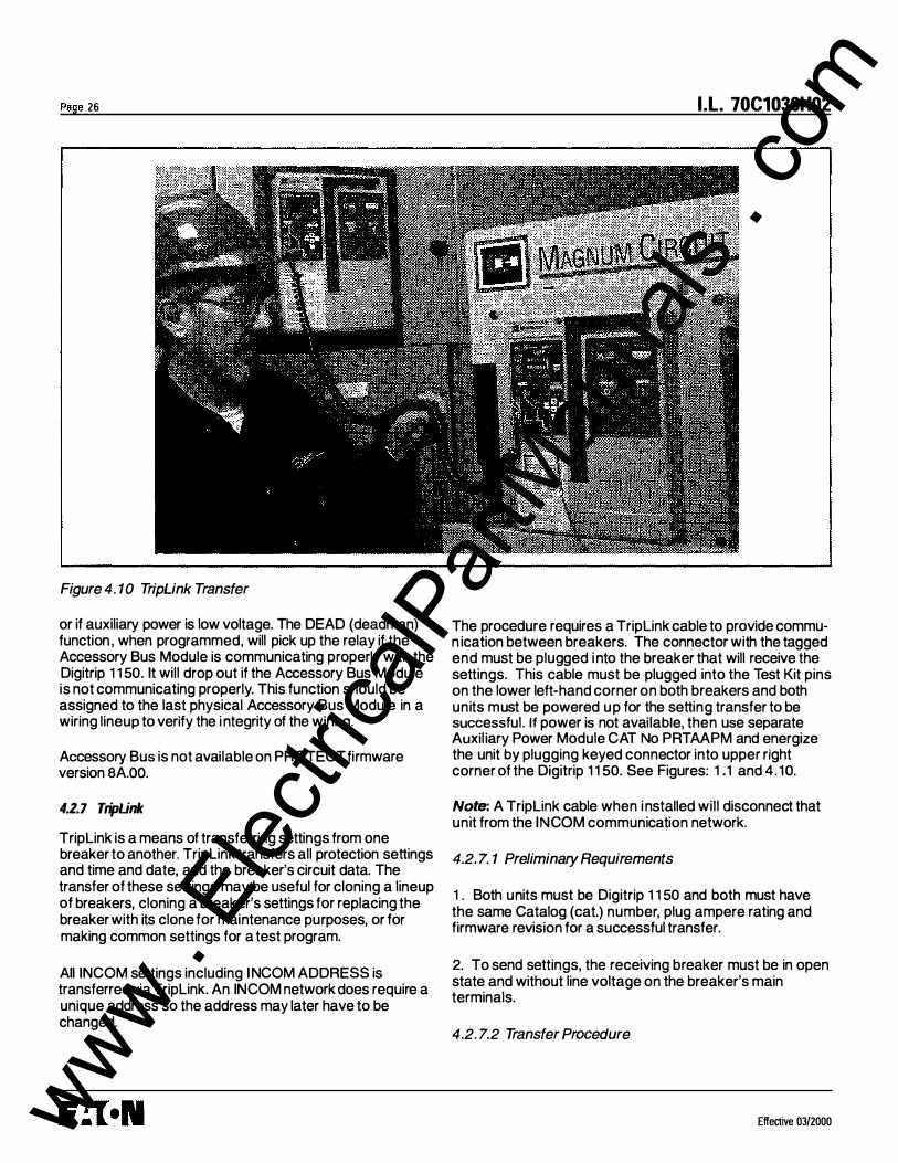
Figure 4. 10 TripLink Transfer
or if auxiliary power is low voltage. The DEAD (deadman) function , when programmed, will pick up the relay if the Accessory Bus Module is communicating properly with the Digitrip 1 1 50. It will drop out if the Accessory Bus Module is not communicating properly. This function should be assigned to the last physical Accessory Bus Module in a wiring lineup to verify the i ntegrity of the wiring.
Accessory Bus is not available on PROTECT firmware version BA.OO.
4.2.7 TripUnk
Triplink is a means of transferring settings from one breaker to another. Triplink transfers all protection settings and time and date, and the breaker's circuit data. The transfer of these settings may be useful for cloning a lineup of breakers, cloning a breaker's settings for replacing the breaker with its clone for maintenance purposes, or for making common settings for a test program.
AII INCOM settings including INCOM ADDRESS is transferred via Triplink. An IN COM network does require a unique address so the address may later have to be changed.
I .L. 70C1036H02
The procedure requires a Triplink cable to provide commun ication between breakers. The connector with the tagged end must be plugged i nto the breaker that will receive the settings. This cable must be plugged into the Test Kit pins on the lower left-hand corner on both breakers and both units must be powered up for the setting transfer to be successful. If power is not available, then use separate Auxil iary Power Module CAT No PRTAAPM and energize the unit by plugging keyed connector into upper right corner of the Digitrip 1 1 50. See Figures: 1 .1 and 4 . 10.
Note: A Triplink cable when i nstalled will disconnect that unit from the INCOM communication network.
4.2. 7. 1 Preliminary Requirements
1 . Both units must be Digitrip 1 1 50 and both must have the same Catalog (cat.) number, plug ampere rating and firmware revision for a successful transfer.
2. To send settings, the receiving breaker must be in open state and without line voltage on the breaker's main terminals.
4.2. 7.2 Transfer Procedure
Effective 03/2000 www . El
ectric
alPar
tMan
uals
. com

I.L. 70C1036H02
Note: It is important to realize that the transfer must be performed from the RECEIVING breaker. (The breaker with the Tag.)
In the Program Triplink menu, if all preliminary requirements are met, the Digitrip 1150 display on the receiving breaker will read "THIS UNIT TO RECEIVE." Otherwise, an error message will appear reading "Triplink CON FIG ERROR" and the display will return to Program Settings menu.
I f the breakers meet the preliminary requirements, the user will be prompted to "PRESS SAVE TO LEARN." When Save is pressed, settings will transfer and a "LOADI NG" message will appear on the display screen. Transfer will be confirmed if successful with a "Triplink TRANSFER COMPLETE" message. Otherwise, "Triplink TRANSFER ERROR" will appear on the display.
In the event of Triplink Configuration Error, check all preliminary requirements as well as the Triplink cable connections. Also ensure that transfer is being initiated and performed on the receiving breaker.
4.2.8 Setting TllfE
In the Digitrip 1150, dates are displayed in DD-MmmYY format (for example , 12-Mar98) and time is displayed in military-style format with hours from 0 to 23. The first screen in PGM SEl\TIME is a view-only screen showing the current time setting for the unit. The View Down button changes screens to the DAY programming screen where the two digit date can be adjusted with the Edit Up or Edit Down pushbuttons. View Down then moves through the programmable three-character MONTH abbreviation, two digit YEAR selection, two digit HOURS, and two digit MINUTES which are all programmed with the Edit Up and/ or Edit Down push buttons. Seconds are not programmable and begin at 00 when time settings are saved. Using View Up in the menu will move the user through the settings in reverse order as described above.
4.2.9 Selecting DISPLAYS
Display programming options control the screens displayed in the Meter Menu. Program Display is located in the PGM SEl\DISPLAY submenu. This submenu lists twenty-two programmable screens. The first screen sets metering for A, B, and C phase currents to AUTO or MANUAL. The remaining twenty-one screens meter current, power and energy and can be set to on or off, depending on user preference. Any settings turned to OFF will not be displayed when METER is selected from the Main Menu.
Effective 03/2000
Page 27
4.2.10 General
4.2. 10. 1 Sliding Demand A sliding demand calculation can be chosen for either the Max kW demand or the Max kVA demand. If neither is required, the user can choose "OFF" by pressing the up/ down Edit Value keys.
4.2. 10.2 Waveform Capture The waveform capture function can be enabled on a 1 , 5 , or 1 0 minute basis. It can also be disabled by selecting "OFF" with the Edit Value keys. If the THD alarm setting has been enabled in the Alarms menu, the waveform capture function will automatically be set to 1 minute and the waveform capture OFF setting will not be available.
4.3 View Settings (VIEW SET)
The VIEW SET menu will allow the user to view all of the settings presented in the PGM SET menus with the exception of the Triplink function. The user cannot edit or change settings in these menus.
4.3.1 Firmware Menu
The Firmware menu enables the user to view the version and revision of the trip unit firmware. The protection firmware is displayed as PROTECT while DISPLAY firmware can be viewed by pressing the up/down View function keys.
4.4 Meter Menu
The METER menu initially will show 6 screens of data via the factory display setup. They are phase current, neutral and ground currents (if supplied) , phase voltages, forward power, power factor and frequency, and energy values. However, the program DISPLAY menu can be used to present metered data relevant to a specific customer application. There are 22 data screens selectable as listed in Appendix D-14 and D-3.
The Demand and the average, minimum and maximum current screens alternate between the data and additional information concerning the measured parameter. The min and max phase currents are actually reset as a group. See Appendix D-3. The OP COUNT screen displays breaker operation where a open/close is registered as one count. The OP COUNT can be reset also when this screen is active.
4.5 Hannonic Menu
The Digitrip 1150 HARMONIC Menu provides capabilities to calculate and display the Total Harmonic Distortion (THD) for phase currents lA, IB and IC as well as IN if available. www .
Elec
tricalP
artM
anua
ls . c
om
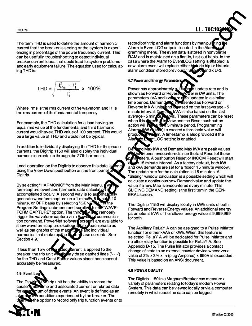
Page 28
The term THO is used to define the amount of harmonic current that the breaker is seeing or the system is experiencing in percentage of the power frequency current. This can be useful in troubleshooting to detect individual breaker current loads that could lead to system problems and early equipment failure. The equation used for calcu lating THO is:
.I 12 !2 THO = .// __.:_:rm:.:..:s:__--..:.11_
12 \J 1 X 1 00%
Where l rms is the rms current of the waveform and 1 1 is the rms current of the fundamental frequency.
For example, the THO calculation for a load having an equal rms value of the fundamental and third harmonic current would have a THO value of 1 00 percent. This would be a large value of THO and would not be typical.
In addition to individually displaying the THO for the phase currents, the Digitrip 1 1 50 will also display the individual harmonic currents up through the 27th harmonic.
Local operation on the Digitrip to observe this data is done using the View Down pushbutton on the front panel of the Digitrip.
By selecting "HARMONIC" from the Main Menu, a waveform capture event and harmonic data calculation is accomplished locally. A second way is to automatically generate waveform capture on a 1 minute, 5 minute, 1 0 minute, or OFF basis by selecting "GENERAL" in the Program Settings submenu and scrolling to the 'WAVEFORM CAPTURE" option. The third way is to remotely trigger the waveform capture via a PowerNet communication command. PowerNet software screens are available to show waveform capture oscillographs of each phase as well as bar graphs of the magnitudes and individual harmonics that make up the three-phase currents. See Section 4.9.
If less than 1 5% of the rated current is applied to the breaker, the trip unit will display three dashed l ines ('- -') for the THO and Crest Factor values since these cannot accurately be measured.
4.6 Event Log
The Digitrip 1 1 50 trip unit has the abil ity to record the cause, timestamp and associated current or related data for a maximum of three events. An event is defined as an alarm or trip condition experienced by the breaker. The user has the option to record only trip function events or to
I.L. 70C1036H02
record both trip and alarm functions by manipulating the Alarm to EventLOG setpoint located in the Alarms programming menu. The event data is stored in nonvolatile RAM and is maintained on a first-in, first-out basis. In the case where the Alarm to EventLOG setting is enabled, a new alarm event will replace either historic trip or historic alarm condition stored previously. See Appendix D-3.
4.7 Power and Energy Parameters
Power has approximately a 1 second update rate and is shown as Forward or Reverse Power in kW units. The parameters kVA and kvar are also updated in a similar time period. Demand kW is presented as Forward or Reverse in kW units and is based on the last average - 5 minute interval. Demand kVA is also based on the last average - 5 minute interval. These parameters can be reset when this screen is in view and the Reset pushbutton action will start a new 5 minute period. Programming Alarms (kW or kVA) to exceed a threshold value will produce an Alarm. A timestamp is also provided if the Alarm to EventLOG setting is enabled.
Demand Max kW and Demand Max kVA are peak values that have been encountered since the last Reset of these parameters. A pushbutton Reset or IN COM Reset will start a new 1 5 minute interval. As a factory default, both kW and kVA demands are set for a "fixed" 1 5 minute window. The update rate for the calculation is 1 5 minutes. A "Sliding" window calculation is a possible setting which will calculate a continuous new Demand value and update the value if a new Max is encountered every minute. This SLIDING DEMAND setting is the first item in the GENERAL screen.
The Digitrip 1 1 50 will display locally in kWh units of both Forward and Reverse Energy values. An additional energy parameter is kVAh. The rollover energy value is 9,999,999 for both.
The Auxiliary RelaY A can be assigned to a Pulse Initiator function for either kVAh or kWh. When this feature is selected, RelaY A will be dedicated for Pulse In itiator and no other relay function is possible for RelaY A. See Appendix D-1 5. The Pulse Initiator provides a contact change of state to an external counter device whenever a value of 2% x 3% x I n (plug Amperes) x 690V is exceeded. This value is based on an ANSI document.
4.8 POWER QUALITY
The Digitrip 1 1 50 i n a Magnum Breaker can measure a variety of parameters relating to today's modern Power System. This data can be viewed locally or via a computer remotely in which case the data can be logged.
Effective 03/2000 www . El
ectric
alPar
tMan
uals
. com

I.L. 70C1036H02
4.8.1 Power Factor, THO and Crest Factor- CF The System Power Factor is a real time measuremen� with approximately a 1 second update rate. The tolerance ts the value ± 0.02. Max PF and Min PF values are historic values that are held until Reset. Total Harmonic Distortion (THO) of each phase and neutral (if valid) and corresponding per harmonic data up to the 27th harmonic and Crest Factor are available via a waveform capture trigger. This waveform capture trigger can be done locally by selecting HARMONIC in the Main Menu or by exceeding a THO alarm threshold programmed by the user. See section 4.8.2.
4.8.2 Alarms
Alarming on low power factor can be accompli�hed by enabling this function in the ALARM programming screen. Any System Power Factor seen by the Digitrip 1150 less than the level programmed will initiate an alarm message on the 24 character display as well as illuminating the yellow LED and communicating to a host computer. . Furthermore, the Auxiliary Relay A can be assigned to thts Low PF Alarm.
The THO alarm feature is an alarm setting with a range of 1 0% to 30% THO that when exceeded will initiate waveform capture and also set the front panel alarm LED. The THO alarm has a 1 minute update rate. The Auxiliary Relay A can also be assigned to a THO alarm.
4.9 WAVEFORM CAPTURE FEATURE
The Digitrip 1150 can respond to a command from a remote master to perform a waveform capture of phase currents lA, IB and IC, as well as waveform IN (on catalog 11 LSI ) or waveform IG (on catalog LSIG employing the source ground configuration). A total of 58 data points per phase per cycle is captured and can be sent to a host computer. From this data, parameters such as [THO], individual harmonics content and waveform displays can be fabricated.
There is a timer in the Digitrip unit that will limit the acceptance of a "WAVEFORM CAPTURE" software command to once per second. Three waveforms are held in a first in, first out manner in the Digitrip's volatile memory.
4.9.1 Six Cycle wavefotm Capture on Trip On tripping events, the Digitrip 1150 will capture the curve waveforms to a buffer. The buffer as a waveform can be displayed on the master computer using the PowerNet software screen (Ref. I .L. 1 7384 for protocol and software commands). The six cycle waveform capture will typically contain one cycle of pre-interruption data and five cycles of
Effective 0312000
Page 29
interruption and post-interruption data for analysis of the power system.
Note: PowerNet communications will require hardware and software specified in the Cutler-Hammer PowerNet Operations Manual and also the Digitrip 1150 Firmware must be DISPLAY VERsion 8 8, REVision 02 or greater and PROTECT VERsion SA, REVision 02 or greater. See Appendix page D-5.
4.9.2 One Cyde Wavefotm Capture There are two methods of obtaining a one cycle waveform capture from the Digitrip 1150. One method is via the PowerNet software to manually request a waveform capture. The second way is to trigger a �aveform cap�ure via an Alarm condition. This is accomplished by entenng the PROGRAM - ALARM screen. Enable the ALARM type of interest as well as ALARM TO EventLOG. The one cycle waveform capture of the currents lA, 18, IC and IN, if applicable, can then be displayed on the master computer for analysis. IG waveform is not displayed for residual ground application. See Appendix D-16.
5.0 TEST PROCEDURES
5.1 General
A wARNING
DO NOT ATTEMPT TO INSTALL, TEST, OR PERFORM MAINTENANCE ON EQUIPMENT WHILE IT IS ENERGIZED. DEATH OR SEVERE PERSONAL INJURY CAN RESULT FROM CONTACT WITH ENERGIZED EQUIPMENT.
DE-EN ERGIZE THE CIRCUIT AND DISCONNECT THE
CIRCUIT BREAKER BEFORE PERFORMING MAINTENANCE OR TESTS.
A wARNING
ANY TRIPPING OPERATION WILL CAUSE DISRUPTION OF SERVICE AND POSSIBLE PERSONAL INJURY, RESULTING IN THE UNNECESSARY SWITCHING OF CONNECTED EQUIPMENT.
www . El
ectric
alPar
tMan
uals
. com
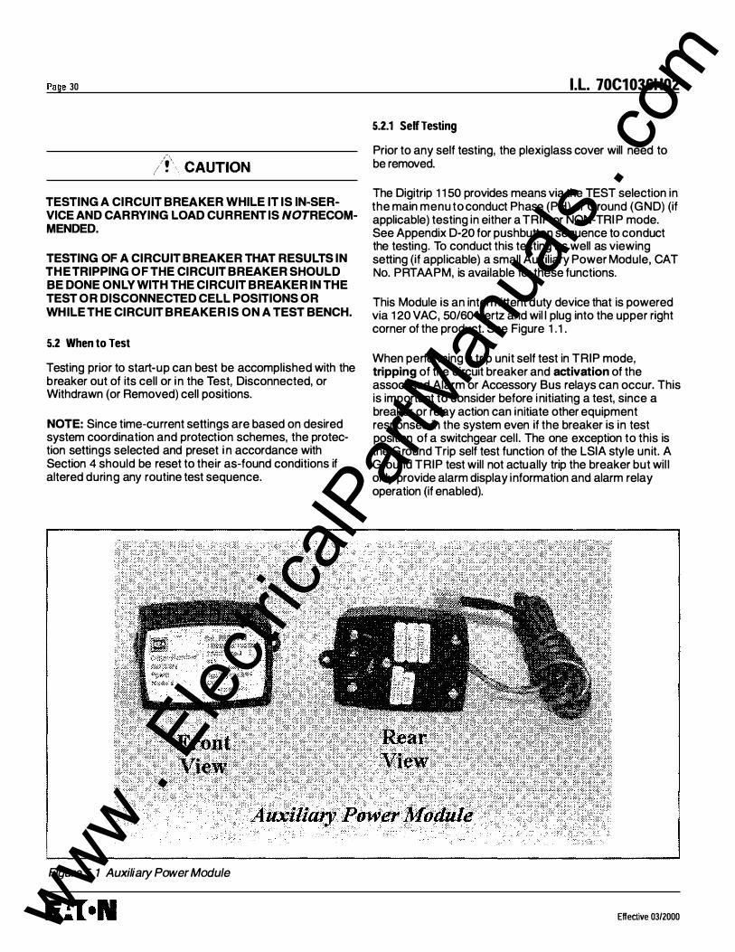
Page 30
/!\ CAUTION TESTING A CIRCUIT BREAKER WHILE IT IS IN-SERVICE AND CARRYING LOAD CURRENT IS NOT RECOMMENDED.
TESTING OF A CIRCUIT BREAKER THAT RESULTS IN THE TRIPPING OF THE CIRCUIT BREAKER SHOULD BE DONE ONLY WITH THE CIRCUIT BREAKER IN THE TEST OR DISCONNECTED CELL POSITIONS OR WHILE THE CIRCUIT BREAKER IS ON A TEST BENCH.
5.2 When to Test
Testing prior to start-up can best be accomplished with the breaker out of its cell or in the Test, Disconnected, or Withdrawn (or Removed) cell positions.
NOTE: Since time-current settings are based on desired system coordination and protection schemes, the protection settings selected and preset i n accordance with Section 4 should be reset to their as-found conditions if altered during any routine test sequence.
Figure 5. 1 Auxiliary Power Module
I.L. 70C1036H02
5.2.1 Self Testing
Prior to any self testing, the plexiglass cover will need to be removed.
The Digitrip 1 1 50 provides means via the TEST selection in the main menu to conduct Phase (PH) or Ground (GND) (if applicable) testing in either a TRIP or NON-TRI P mode. See Appendix D-20 for pushbutton sequence to conduct the testing. To conduct this testing as well as viewing setting (if applicable) a small Auxiliary Power Module, CAT No. PRTAAPM, is available for these functions.
This Module is an intermittent duty device that is powered via 1 20 VAC, 50/60 Hertz and wil l plug into the upper right corner of the product. See Figure 1 . 1 .
When performing a trip unit self test in TRIP mode, tripping of the circuit breaker and activation of the associated Alarm or Accessory Bus relays can occur. This is important to consider before i nitiati11g a test, since a breaker or relay action can initiate other equipment responses in the system even if the breaker is in test position of a switchgear cell . The one exception to this is the G round Trip self test function of the LSIA style unit. A Ground TRIP test will not actually trip the breaker but wil l only provide alarm display information and alarm relay operation (if enabled).
Effective 03/2000 www . El
ectric
alPar
tMan
uals
. com

I.L. 70C1036H02
In the NON-TRI P mode of self test, the breaker trip function and any associated relay will not operate when test alarm or test trips occur. The front panel indicating LED will light as well as display alarm/trip cause information.
The Self Test function cannot be entered if an alarm is already present. This alarm will need to be cleared before any self testing can be conducted. The self test function will terminate if any of the following conditions occur after the start of testing:
1. Any real Phase current exceeds an alarm setting 2. Any real Ground current exceeds 0 . 1 per unit. 3. I f real Phase current exceeds 1 x (/r) while
conducting a NON-TRIP test. 4. If real Phase current exceeds 0.5 x (/r) while
conducting a TRIP test.
5.2.2 Functional Field Testing
/f' . CAUTION
PERFORMING TESTS WITHOUT THE CUTLER-HAMMER-A PPROVED TEST KIT MAY DAMAGE THE DIGITRIP UNIT.
Use the test receptacle to verify a functional load test of a major portion of the electronic circuitry of the Digit rip and the mechanical trip assembly of the breaker. The testing can determine the accuracy of the desired trip settings by performing Long Delay, Short Delay, and Ground Fault functional tests. The Cutler-Hammer-approved test kit is listed below.
Model Test Kit Oigitrip 1 1 50 Test Kit (1 400481 G02R, 1 40 0481 G02RR,
1 400481 G03, or G04) with Test Kit Adapter 8779C02G04
The test port is located on the front left-hand corner of the DT1150 units (see Figure 1.1). To access the port, remove the plexiglass cover from the front of the circuit breaker. Using a small screwdriver, gently pry up on the test port cover to remove this item.
The test kit authorized by Cutler-Hammer for use with the Digitrip units plugs into the test port of the unit and provides a secondary injection test that simulates currents from the current transformers. Existing test kits, styles 140D481G02R, 140D481G02RR, 140D481G03 or G04, along with the Magnum Test Kit Adapter 8779C02G04, can be used to test the trip unit and breaker.
Effective 03/2000
5.3 Performance Testing for Ground Fault Trip Units
5.3.1 Code Requirements
Page 31
The NEC, under Article 230-95-C, requires that any ground fault protection system be performance tested when first installed. Conduct tests in accordance with the approved instructions provided with the equipment. Make a written record of this test and make the results available to the authority having inspection jurisdiction.
5.3.2 Standard Requirements
As a follow-up to the basic performance requirements stipulated by the NEC, UL Standard No. 1 053 requires that certain minimum instructions must accompany each ground fault protection system. These statements (Section 5.4.3), plus a copy of the record forms (Figures 8 . 1, 8.2, and 8.3), are included as part of this Instructional Leaflet .
5.3.3 General Test Instructions
The interconnected system must be evaluated only by qualified personnel and in accordance with the equipment assembler's detailed instructions.
To avoid improper operations following apparently correct simulated test operations, the polarity of the neutral sensor connections (if used) must agree with the equipment assembler's detailed instructions. Where a question exists, consult the specifying engineer and/or equipment assembler.
A wARNING
PERSONAL INJURY CAN OCCUR WHEN WORKING ON P OWER SY STEMS. ALWAY S TURN OFF P OWER SUPP LY ING BREAKER BEFORE CONDUCTING TESTS. TEST OUT OF THE CELL, IF POSSIBLE. THERE IS A HAZARD OF ELECTRICAL SHOCK OR BURN WHENEVER WORKING IN OR AROUND ELECTRICAL EQUIPMENT.
Verify the grounding points of the system using highvoltage testers and resistance bridges to ensure that ground paths do not exist that could bypass the sensors.
Use a low-voltage (0 to 24 volt), high-current, AC source to apply a test current of 125 percent of the Digitrip unit pickup setting through one phase of the circuit breaker. This should cause the breaker to trip in less than 1 second and operate the alarm indicator. Reset the Digitrip and then reclose the breaker. Repeat the test on the other two phases (see Figure 5.2).
www . El
ectric
alPar
tMan
uals
. com

Page 32
Apply the same current as described above through one phase of the breaker, returning through the neutral sensor. The breaker should not trip, and the alarm indicator should not operate. Repeat the test on the other two phases.
Suitable , Conducto<s�
Low-VOltage ac Current Sou!'C<I
'
(Primary Disconnect
. r r · =�
l f _f_fj�'
Figure 5.2 Connection Details for Conducting Single Pole, Single Phase Current Tests with the Breaker Removed from the Cell
Apply the same current as described above through any two phases of the breaker. The breaker should not trip. Repeat the test using the other two combinations of breaker phases (see Figure 5.3)
- -Suitabte : CondUCIOO!�
Low-VoHage e' acCurrent � Source ,
(Ptimary Disconnecl Stabs-
- Wilen Orawoot
--- -) : Polarity &
(/--+ :
Figure 5.3 Connection Details for Conducting Single Phase Current Tests with the Breaker Removed from the Cell
I !\ CAUTION
RESTORE ALL TEMPORARY CONNECTIONS MADE FOR THE PURPOSE OF CONDUCTING TESTS TO PROPER OPERATING CONDITIONS BEFORE RETURN· lNG THE BREAKER TO SERVICE.
I.L. 70C1036H02
Record the test results on the test form provided with the equipment (Figure 8.3).
6.0 BATTERY
6.1 General
The battery plays no part in the protection function of the trip unit.
As indicated in Figure 3. 1 , the battery is provided to flash and power the red LED indication on the mimic curve. The battery is located under the rating plug door. A battery test pushbutton and a green Battery Test LED are also provided.
A second function of the battery is to provide backup power for the clock chip in the unit. The clock is used to timestamp trip and alarm events.
On initial installation of the circuit breaker, pull out the insulating tab with a quick pull. See Figure 6. 1 . This will activate the battery. Check the battery status using the Battery Test pushbutton.
6.2 Battery Test
The battery is a long-life, lithium, camera-type unit. Check the status of the battery at any time by pressing the Battery Test pushbutton and observing the green LED. I f the Battery Test LED does not light green, replace the battery. The condition of the battery has no effect on the p rotection function of the trip unit. Even with the battery removed, the unit will still trip the breaker in accordance with its settings. However, without the battery, the Cause of Trip LED will not be lighted red if auxiliary power is lost to the Digitrip. If the battery is replaced, one or more of the Cause of Trip LEOs may be illuminated. Push the red Reset/Battery Test button to turn off the indicators; the trip unit will be ready to indicate the next cause of trip.
6.3 Battery lnstalladon and Removal
The 3-volt lithium cell battery (see Figure 6. 1 ) is easily removed and replaced. The battery is located in the cavity adjacent to the rating plug mounting screw, but i s not part of the rating plug. Insert a small screwdriver at the left side of the rating plug, and to the left of the word OPEN, to open the rating plug door. Remove the old battery by pulling up on the removal tab that wraps under the battery cell. When inserting the new cell, pay special attention to ensure that the proper polarity i s observed. The main body of the battery is the positive (+) side.
Effective 03/2000 www . El
ectric
alPar
tMan
uals
. com
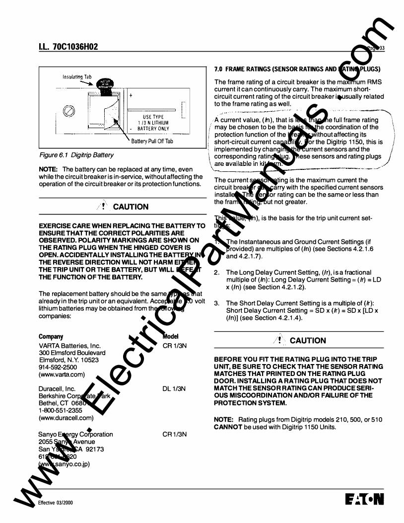
I.L. 70C1036H02
+
USE TYPE 1 / 3 N liTHIUM
• BATTERY ONlY
Battery Pull Off Tab
Figure 6. 1 Digitrip Battery
NOTE: The battery can be replaced at any time, even while the circuit breaker is in-service, without affecting the operation of the circuit breaker or its protection functions.
/ ! \ . CAUTION
EXERCISE CARE WHEN REPLACING THE BATTERY TO ENSURE THAT THE CORRECT POLARITIES ARE OBSERVED. POLARITY MARKINGS ARE SHOWN ON THE RATING PLUG WHEN THE HINGED COVER IS OPEN. A CCIDENTA LLY INSTALLING THE BATTERY IN THE REVERSE DIRECTION WILL NOT HARM EITHER THE TRIP UNIT OR THE BATTERY, BUT WILL DEFEAT THE FUNCTION OF THE BATTERY.
The replacement battery should be the same type as that already in the trip unit or an equivalent. Acceptable 3.0 volt lithium batteries may be obtained from the following companies:
Company VARTA Batteries, Inc. 300 Elmsford Boulevard Elmsford, N.Y. 10523 914-592-2500 (www.varta.com)
Duracell , Inc. Berkshire Corporate Park Bethel, CT 06801 1-800-551-2355 (www.duracell.com)
Sanyo Energy Corporation 2055 Sanyo Avenue San Ysidro, CA 92173 619-661-6620 (www.sanyo.co.jp)
E ffective 03/2000
Model CR 1/3N
DL 1/3N
CR 1/3N
Page 33
7.0 FRAME RATINGS (SENSOR RATINGS AND RATING PLUGS)
The frame rating of a circuit breaker is the maximum RMS current it can continuously carry. The maximum shortcircuit current rating of the circuit breaker is usually related to the frame rating as well.
. . . . .. , .... .. . -� -A current value, (h1), that is less than the full frame rating \ may be chosen to be the basis for the coordination of the \
i protection function of the breaker without affecting its J short-circuit current capability. For the Digitrip 1150, this is I implemented by changing the current sensors and the j i\ corresponding rating plug. These sensors and rating plugs ) are available in kit form. /
�:.=---=--_____:...------·-., .- _, ..
The current sensor rating is the maximum current the circuit breaker can carry with the specified current sensors installed. The sensor rating can be the same or less than the frame rating, but not greater.
This value, (h1), is the basis for the trip unit current settings:
1. The Instantaneous and Ground Current Settings (if provided) are multiples of (In) (see Sections 4. 2. 1.6 and 4.2. 1.7).
2 . The Long Delay Current Setting, (/r), is a fractional multiple of (In) : Long Delay Current Setting = (lr) = LD x (/n) (see Section 4.2.1.2).
3. The Short Delay Current Setting is a multiple of (/r): Short Delay Current Setting = SD x (/r) = SD x [LD x (/n)] (see Section 4.2.1.4).
/f CAUl"ION
BEFORE Y OU FIT THE RATING P LUG INTO THE TRIP UNIT, BE SURE TO CHECK THAT THE SENSOR RATING MATCHES THAT PRINTED ON THE RATING PLUG D OOR. INSTALLING A RATING PLUG THAT DOES NOT MATCH THE SENSOR RATING CAN PRODUCE SERI· OUS MISCOORDINATION A ND/OR FAILURE OF THE PROTEC"rJ ON SYSTEM.
NOTE: Rating plugs from Digitrip models 210, 500, or 5 10 CANNOT be used with Digitrip 1150 Units.
www . El
ectric
alPar
tMan
uals
. com
Page 34
8.0 RECORD KEEPING
Use the forms shown in Figures 8. 1 and 8.2 for record keeping. Fill in these forms, giving the indicated reference information and initial time-current trip function settings. If desired, make a copy of the form and attach it to the interior of the breaker cell door or another visible location. Figure 8.3 provides a place for recording test data and actual trip values.
Ideally, sheets of this type should be used and maintained by those personnel in the user's organization that have the responsibility for protection equipment.
9.0 REFERENCES
9.1 Magnum and Magnum OS Circuit Breakers
I .B. 2C1 2060 Magnum DS Breaker Instructions
I .B. 2C1 3060 Magnum I . Breaker Instructions
4A36346 Zone I nterlocking Application with NonMagnum Breakers
9.2 Time-Current Curves
The Time-Current Curves are l isted below for particular trip unit models. All protection function time-current settings should be made following the recommendations of the specifying engineer in charge of the installation.
70C1041 Digitrip 1 1 50/1 1 50i 70C1043 Digitrip 1 1 50/1 1 50i 70C1034 Digitrip 1 1 50/1 1 50i 70C1 035 Digitrip 1 1 50/1 1 50i 70C1 038 Digitrip 1 1 50 IEEE 70C1 039 Digitrip 1 1 50 IEEE 70C1040 Digitrip 1 1 50 IEEE 70C1031 Digitrip 1 1 50i IEC-A 70C1 032 Digitrip 1 1 50i IEC-B 70C1 033 Digitrip 1 1 50i IEC-C
Ground (Earth) Trip Instantaneous Trip 12t Long Time Trip 14t Long Time Trip Moderately Inverse Very I nverse Extremely Inverse Normal Inverse Very Inverse Extremely Inverse
l .l. 70C1036H02
Effective 0312000 www . El
ectric
alPar
tMan
uals
. com

l.l. 70C1036H02 Page 35
DIGITRIP
TRIP FUNCTION SETIINGS
Circuit No./ Address Breaker Shop Order Reference
PER UNIT MULTIPLIERS
Rating Plug Amperes k Continuous Ampere Rating (In) = LDS x In
Ampere Trip Per Unit Equivalent
Function Setting Multi Setting Time Delay
In st. kl >< Long Delay kl Sec.
Short Delay k Sec.
Ground Fault kl Sec.
Date By
Figure 8. 1 Typical Trip Function Record Nameplate
Effective 03/2000 www . El
ectric
alPar
tMan
uals
. com
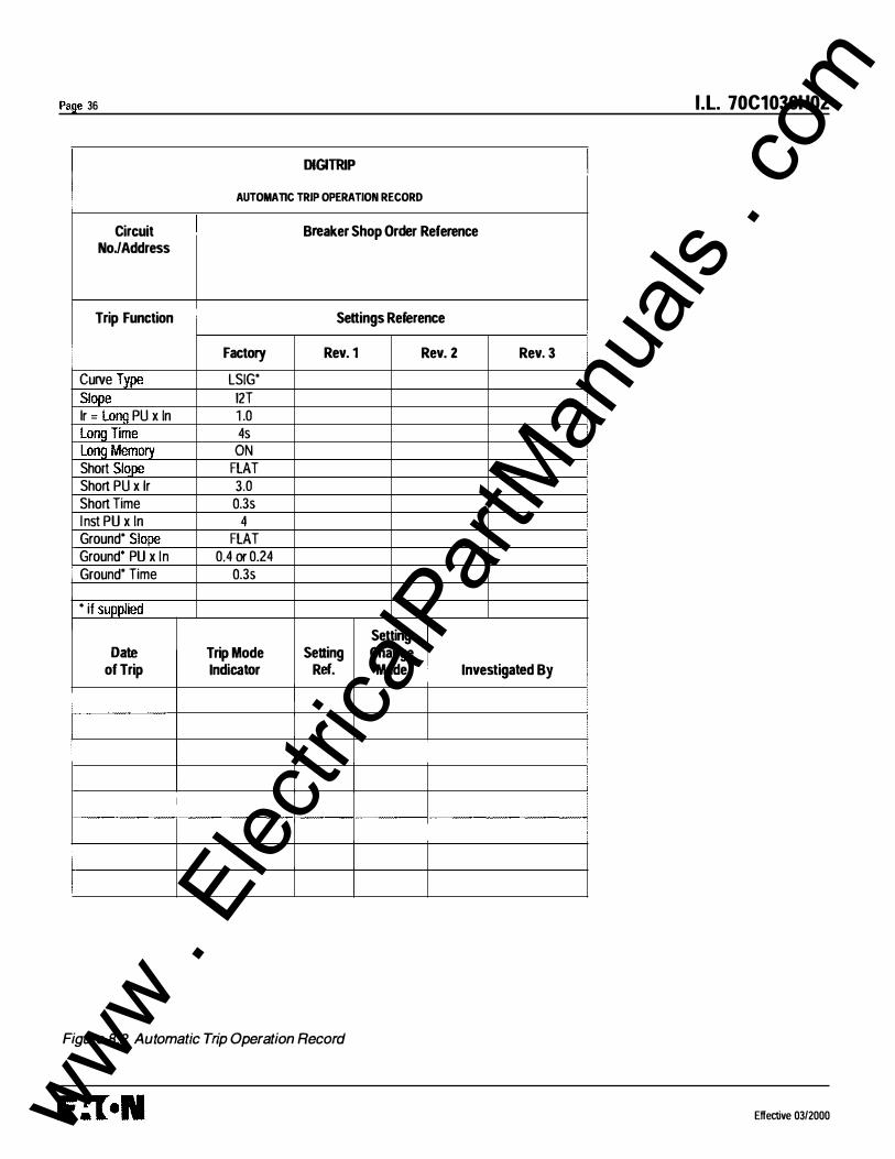
Page 36
i
Circuit NoJAddress
Trip Function
Curve Type Slope lr = LonQ PU x In Long Time
. Long Memory Short Slo_pe Short PU x lr Short Time l nst PU x In Ground* Slope Ground* PU x In
• Ground* Time
• if supplied
Date of Trip
!
I !
I
I
DIGITRIP
AUTOMATIC TRIP OPERATION RECORD
Breaker Shop Order Reference
Settings Reference
Factory Rev. 1 Rev. 2 Rev. 3
LSIG*
12T 1 .0 4s
ON FLAT 3.0 0.3s
4 FLAT
0.4 or 0.24 0.3s
Setting Trip Mode Setting Change Indicator Ref. Made Investigated By
Figure 8.2 Automatic Trip Operation Record
I .L. 70C1036H02
I
: .
I I
I
I I I I
I I ! I
J I
Effective 0312000 www . El
ectric
alPar
tMan
uals
. com

l.l. 70C1036H02
GROUND FAULT TEST RECORD FORM
Ground Fault Test Record should be retained by those in charge of the building's electrical installation in order to be available to the authority having jurisdiction.
Test Date Circuit Breaker Results Tested by Number
•
Figure 8.3 Typical Performance Test Record Form
Effective 03/2000
Page 37
www . El
ectric
alPar
tMan
uals
. com

Page 38
NOTICE
THE PROVISION FOR ZONE INTERLOCKING IS STANDARD ON MAGNUM CIRCUIT BREAKERS WITH DIGITRIP 1 1 50 TRIP UNITS FOR SHORT TIME AND GROUND FAULT FUNCTIONS. THE APPROPRIATE JUMPER TO ·rERMINAL BB AND B9 MUST BE ADDED ON THE BREAKER IF ZONE INTERLOCKING IS NOT DESIRED OR IF FIELD ·rESTING IS DESIRED.
APPENDIX A Zone Interlocking Examples
CASE 1 : There is no Zone Selective Interlocking. (Standard time delay coordination is used.)
Assume that a ground fault of 2000 Amperes occurs and refer to Figure A. 1 .
Fault at location 3 The branch breaker wil l trip, clearing the fault in 0.1 seconds.
Main and feeder trip units will also begin to time out and, in the event that the branch breaker does not clear the fault, the feeder breaker will clear the fault in 0.3 seconds (as above). Similarly, in the event that the feeder breaker does not clear the fault, the main breaker will clear the fault in 0.5 seconds (as above).
Fault at location 2 The feeder breaker will trip, clearing the fault i n 0.3 seconds.
The main trip unit will also begin to time out and, in the event that the feeder breaker Z2 does not clear the fault, the main breaker will clear the fault i n 0.5 seconds (as above).
Fault at location 1 The main breaker will trip, clearing the fault i n 0.5 seconds.
CASE 2: There is Zone Selective Interlocking.
Assume a ground fault of 2000 Amperes occurs and refer to Figure A.1 .
Fault at location 3 The branch breaker trip unit wil l initiate the trip i n 0.045 seconds to clear the fault and the branch will send a
I.L. 70C1036H02
restraint signal to the feeder trip unit; the feeder wil l send a restraint interlocking signal to Z1 .
Main and feeder trip units wil l also begin to time out and, in the event that the branch breaker does not clear the fault, the feeder breaker will clear the fault in 0.3 seconds (as above). Similarly, in the event that the feeder breaker does not clear the fault, the main breaker will clear the fault in 0 .5 seconds (as above).
Fault at location 2 The feeder breaker trip unit will initiate the trip in 0.045 seconds to clear the fault and will send an interlocking signal to the main trip unit.
The main trip unit will also begin to time out and, in the event that the feeder breaker Z2 does not clear the fault, the main breaker will clear the fault i n 0.5 seconds (as above).
Fault at location 1 There are no interlocking signals. The main breaker trip unit will initiate the trip in 0.045 seconds.
Figure A.2 presents a Zone Selective Interlocking connection diagram for a system with two main breakers from incoming sources and a bus tie breaker. Note that the blocking diode 01 is needed so that the feeder breakers can send interlocking signals to both the main and the tie breakers and prevent the tie breaker from sending an interlocking signal to itself.
Effective 03/2000 www . El
ectric
alPar
tMan
uals
. com

I .L. 70C1036H02
Zone 3
3
Figure A. 1 Typical Zone Interlocking
0 1 1 N4004
0. 1 Sec 0 . 1 Sec
NOTES: A 1 : Wiring to be twisted pair of AWG
No. 1 4 to AWG No. 20. Route Zone I nterlocking wiring separate from power conductors. DO NOT GROUND any Zone Interlock Wiring.
A2: The maximum distance between first and last zone is 250 feet ( 76 m) .
A3: A maximum of 20 breakers may be connected in parallel in one zone.
Legend
= Common (Ungrounded) · 8 7--C o n tact
= Zone Out Output Signal - 89 -C o n tact to Hig her Level Zone
= Zone In Input Signal - 88 � C o n tact from Lower Level Zone
2
/ = Fault at location 2
0.5 Sec
0. 1 Sec 0 . 1 Sec 0. 1 Sec
Figure A.2 Typical Zone Interlocking Connections with Two Main Breakers (M1, M2) and a Tie Breaker (T)
Effective 03/2000
Page 39
www . El
ectric
alPar
tMan
uals
. com

Page 40 I.L. 70C1 036H02
Appendix B Troubleshooting Guide
No auxiliary power input.
Wrong auxiliary power Check voltage input terminals Refer to Section 1 .6. 1 . voltage. A14·A15.
As soon as current starts to Rating plug is not installed or Install rating plug and/or flow through the breaker, it is loose. check for loose connections. trips and the Instantaneous
Rating plug is open internally. Replace rating plug. trip LED comes on.
Trip unit is malfunctioning. Replace trip unit.
LED does not come on when Battery installed backwards. Install correctly. battery check button is
Dead battery. Replace battery. pressed.
Trip unit is malfunctioning. Replace trip unit
Breaker trips on ground fault. There actually is a ground Find location of the fault. fault
On 4-wire residual systems, Check connections at See Section 2.3. Notes. the neutral current sensor terminals B4 and B5. Check may not have the correct ratio that the neutral current sensor or be properly connected. ratio matches the breaker.
Check that the connections from the neutral current sensor to the breaker are not reversed. Check B6, B7 for correct programming of jumper.
Trip unit is malfunctioning. Replace trip unit
Breaker trips too rapidly on Connection from Zout to Zin is Make connections B8 to B9. Refer to Appendix A. ground fault or short delay missing. (Zone Selective Interlocking Trip unit settings are not Change settings. not used).
correct.
Trip unit is malfunctioning. Replace trip unit
Breaker trips too rapidly on Long Time Memory selected. Disable Long Memory. long delay.
Trip unit settings are not Change settings. Long Time correct. Delay setting is based on 6xk.
Effective 03/2000 www . El
ectric
alPar
tMan
uals
. com
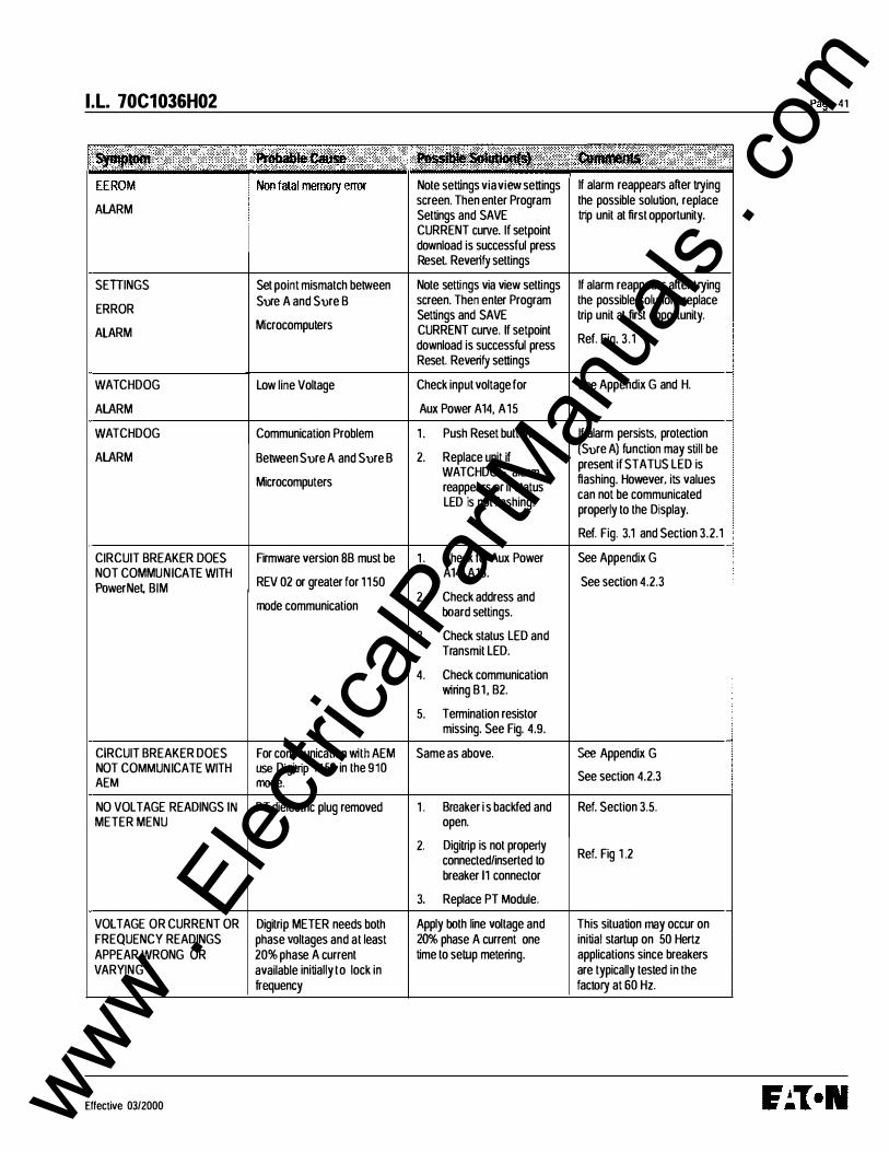
I.L. 70C1036H02 Page 41
Note settings via view settings If alarm reappears after trying
ALARM screen. Then enter Program the possible solution, replace Settings and SAVE trip unit at first opportunity. CURRENT curve. If setpoint download is successful press Reset. Reverify settings
SETIINGS Set point mismatch between Note settings via view settings If alarm reappears after trying
ERROR Sure A and Sure B screen. Then enter Program the possible solution, replace
Settings and SAVE trip unit at first opportunity.
ALARM Microcomputers CURRENT curve. If setpoint
download is successful press Ref. Fig. 3.1
Reset. Reverify settings
WATCHDOG Low line Voltage Check input voltage for See Appendix G and H.
ALARM Aux Power A14, A15
WATCHDOG Communication Problem 1 . Push Reset button. If alarm persists. protection
ALARM Between Sure A and Sure B 2. Replace unit if (Sure A) function may still be
WATCHDOG alarm present if STATUS LED is
Microcomputers reappears or if status flashing. However. its values can not be communicated
LED is not flashing. properly to the Display.
Ref. Fig. 3.1 and Section 3.2.1
CIRCUIT BREAKER DOES Firmware version SB must be 1 . Check for Aux Power See Appendix G NOT COMMUNICATE WITH
REV 02 or greater for 1 1 50 A14, A15.
See section 4.2.3 PowerNet BIM mode communication
2. Check address and board settings.
3. Check status LED and Transmit LED.
4. Check communication wiring B1 , B2.
5. Termination resistor missing. See Fig. 4.9.
CIRCUIT BREAKER DOES For communication with AEM Same as above. See Appendix G NOT COMMUNICATE WITH use Digitrip 1 1 50 in the 910
See section 4.2.3 AEM mode.
NO VOLT AGE READINGS IN PT dielectric plug removed 1 . Breaker i s backfed and Ref. Section 3.5. METER MENU open.
2. Digitrip is not properly Ref. Fig 1 .2 connected/inserted to
breaker 11 connector
3. Replace PT Module.
VOLT AGE OR CURRENT OR Digitrip METER needs both Apply both line voltage and This situation may occur on FREQUENCY READINGS phase voltages and at least 20% phase A current one initial startup on 50 Hertz APPEAR WRONG OR 20% phase A current time to setup metering. applications since breakers VARYING available initially to lock in are typically tested in the
frequency factory at 60 Hz.
Effective 03/2000 www . El
ectric
alPar
tMan
uals
. com
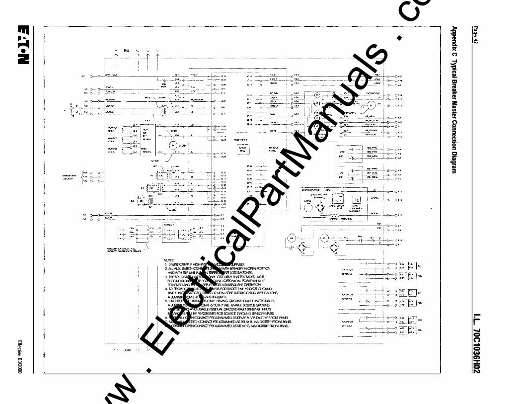
� i· lOAD
0 i
NOlES: 1 . 3 'MilE O<lvP IF HIGH INSfffi!P M::IUE IS SJ'ItiiD.
2. JlU AlK � o::MIClS�'MlH llll61'KER IN CflEN PCffi1CN JINOWTH 1llP UNT IN'1\ICNffi!PPED' SWE (OlS 9Mlc:HES).
3. lHE"m' I:E'I1CE WISI'ID11CN"L OflaJlllYltW�DES A0.5 SECX;N)SISN'< PUll£ Fa<O.C!iiNGOPEAAnCN FOMR MBT BE llEM:M3::>AI'D lHENllf.JlfRIED Fa< ArulSEQJENf Cl'ffi"/llN.
4. 10 fi<CMI:FSElECJEDTIM; DElAYS Fa<::H:RTnMOAI\Q'CRGOJ\D
TIM; FU\CIICN; FClllESllNGCR N::N-ZO\E IM811.c:x:MNG .o!'R.IO>.nC1\5,
A,LI',fffi RlCMB-8lOB·91S !RlJRfD. 5 ON ll-IICE PO E BRfAl<81S CNY, '""VlNG GROJN) FAll T FUI'CllCN'oLirl,
A,LI',fffi li'&JlUID RlCMB-6 TOB·7 'M.l EN/!8LE &:UlCE GOJ\D
fi'IULT SENSING JINO CISI'elE I1ESDJil( Gl<O.J'D li"lli SENSING N'lJIS B·A A'lDB·5 Wll B F REA'JSGN3::l Fell &:UlCE GflO.ND SINO'llf'f\JTS
6 �� Y CflEN CCNf!lCT PfOGIWJM':D /lS llHJlil A W. DIGlll!PFIO\If 11\J'R. 7. �LY QCSED CO'>lJii!D fl1CJGilAMv'ED /lS RB.AY B. VIA DIGlll!P RlCNI FI'N!i. 8. �LY CflEN CCNf!lCT PfOGlWJM':D /lS RElAY C 1M. DG1RP rn::Nr �L
I -1 '< "5!. n !!.
r f I it � �. g X i
-.
r-..... = (") .... = w en ::z: = N
www . El
ectric
alPar
tMan
uals
. com
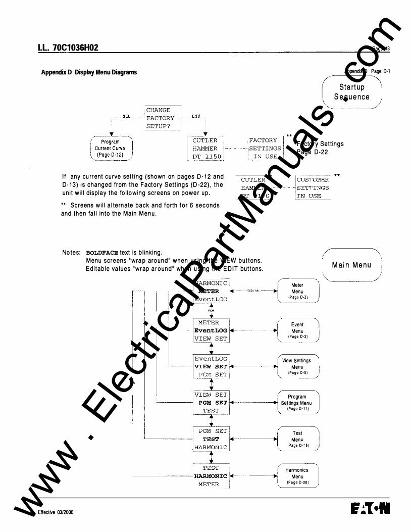
I.L. 70C1036H02
Appendix D Display Menu Diagrams
� CHANGE FACTORY SETUP ?
Page 43
Appendix D Page D-1
if Startup·········-�
\__ S eq u e n��_/
,-------......., * * r- .L-� : Program • Current
.
C
.
ur
..
ve
��2) : FACTORY
I SETTINGS L IN USE .
Facto ry Settings P age D-22
I f any cu rrent cu rve sett ing {shown on pages D - 1 2 a n d D- 1 3) is changed from t h e Factory Sett ings (D -22) , t h e u n it w i l l d isplay the fo l lowing screens on powe r u p .
CUTLER f
• • Screens w i l l a l te rn ate back and forth for 6 seconds and then fa l l into the Main M e n u .
Notes: BOLDFACE text is b l ink ing .
Effective 03/2000
Menu screens " w ra p aro u n d " when u s i n g t h e V I EW buttons. Editable va l u es "wrap a r o u n d ' when u s i ng the E D IT buttons.
_j f-HARMONI C : • Meter 1 c---...,-�-�-····:· : METER �osctm---� Menu
I EventLOG �� �j
ESC
• VIEW
METER E 1 EventLOG ,.,._. ___ ······· -.J M
veenn� j.
VIEW S ET . (Page D-31 "----·---� EventLOG : 1 View Settings
'-----I VIPG
EWM
SS ____ EE:::
T 1�<���:-.r------..,llo. Menu
� ( (Page D-5)
Program i<of- ···········-----.1 Settings Menu (Page 0·1 1 )
r Test \ ----11>1>1 Menu I "-��:1�
Harmonics Menu
(Page 0·20)
Mai n Menu
www . El
ectric
alPar
tMan
uals
. com
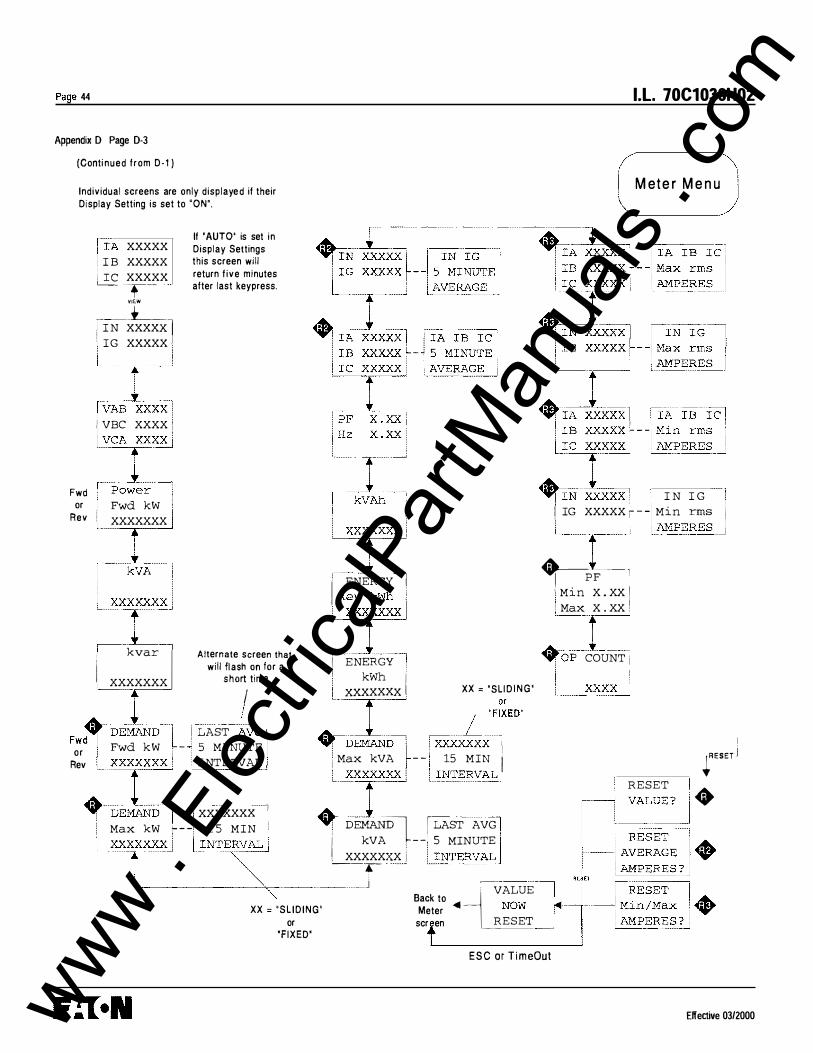
Page 44
Appendix D Page D-3
(Conti nued from D- 1 )
Individual screens are only displaye d if their Display Setting is set to 'ON".
xxxxx IB XXXXX
� xxxxx T-
V lEW
_____ :t-___ 1 IN xxxxX.l ' IG xxxxx l L.---.---
l vAB !XXXX j I VBC XXXX 1 i VCArX j
If 'AUTO' is set in Display Settings this screen will return f ive minutes after last keypress.
I.L. 70C1036H02
M et e r M e n u
I N I G Fwd 'Power ' or . Fwd kW 1
Rev i XXXXXXX I � Ih � ' ' I IG XXXXX ;- Min rms 1 l.}\MP_ERES _..J t �]XXX , _ 1 _;
,_PF -- , ' Min X . XX I ! Max X . XX : I ENERGY!
�x�r: Rl�� • kvar I Alternate screen that � _ [ _ _ I XXXXXXX
will ;1::� ���or a I EN���y I' �OP COUNT j
�- I xxxxxxx XX = 'SLI D I N G '
Fwt·w1D-L LAST �VG � 1
J ���EO
or Fwd kW 1 - 5 MINUTE ....,.. DEMAND 1 XXXXXXX ' Rev XXXXXXX . INTERVAL i Max kVA - - 1 15 MIN i +nl 1 1 xxxxxxx '
+ xxrxxx _ __ I Max kW !- - - 1 5 MIN I ' DE�� l LAST AVG
I ""f i I INTES:"
I' k
.
VA • -- 5 MINUTE
. XXXXXXX I ·-- .-- .
------- ··--·-··-- . _j - ---··· -----.
Back to -L' VALUE XX = "SL ID ING" Meter <41 NOW 1 r<ll t----1 ----1
or scr en RESET __ •
'FIXED'
ESC or T imeOut
I
RESET
I fESET j •
Elfective 03/2000 www . El
ectric
alPar
tMan
uals
. com
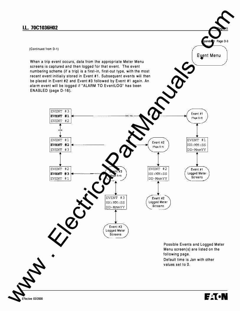
l.l. 70C1 036H02
(Continued f rom D- 1 )
When a tr ip event occ u r s , d a ta from the a pp ro p r i a te M e t e r M e n u screens i s captured a n d t h e n logged f o r t h a t event . T h e event n u m be ri n g scheme ( if a t r i p) is a f i rst- i n , f i rst-out type, w i th the most recent event i n it i a l l y stored i n Event # 1 . S u bsequent eve n ts wi l l then
be p laced in Event #2 and Event #3 fol lowed by E ve nt #1 ag a i n . An a l a r m event wi l l be logged i f " A LA R M TO EventLO G " h a s been E N A B L E D (page D - 1 6) .
EVENT # 3 EVENT #1 � ESC I SEL
EVENT # 2
i VIEW
EVENT # 1 EVENT #2 EVENT # 3
Page 45
Appendix D Page D-3
Event Menu
EVENT # 1 HH : MM: : SS DD-MrnrnYY
EVENT # 2 EVENT # 3 1-4---------tlo! EVENT # 1
EVENT # 2 HH : MM: : S S DD-MrnrnYY
Effective 03/2000
EVENT # 3 HH : MM: : S S DD- MmmYY
Event #3 Logged Meter
S c reens
Poss ib le Events a nd Logged M et e r M e n u screen ( s) a r e l i sted o n t h e
fol l ow i n g page .
Default t i m e i s Jan with oth e r
va lues s e t t o 0 .
www . El
ectric
alPar
tMan
uals
. com
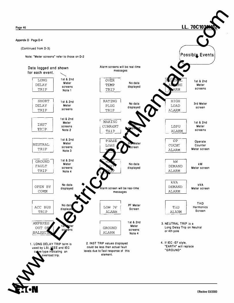
Page 46
Appendix 0 Page 0-4
(Conti n ue d from D-3)
Note: 'Meter scre ens' refe r to those on 0-2
Data l ogged a n d shown f o r each event .
LONG DELAY
TRI P
SHORT DELAY
TRI P
� p
NEUTRAL T R I P
GROUND FAULT
TRI P
OPEN BY COMM
ACC BUS TRI P
1 st & 2nd M eter
screens Note 1
1 st & 2nd Meter
screen s
1 st & 2 n d Meter
scre e n s Note 2
1 st & 2nd M eter
screens Note 3
1 st & 2nd M eter
screens Note 4
No data displayed
N o data d isplayed
1 st Meter screen s
1 . LONG D E L A Y T R I P term i s u s e d by L S I , I E E E and IEC
curve type ind icating an overload trip.
Alarm screens wi l l be real-time m essages
RAT ING PLUG TRI P
N o data disp layed
No data d isplayed
No data d isplayed
3rd M eter screen
N o data d isplayed
Alarm screen will be real-time messages
GROUND ALARM
PF Meter Screen
1 st & 2nd Meter
screens Note 4
2. I N ST TRIP val u es d isplayed could be less than actual fau l t
levels due to last response of this e lement.
l.l. 70C1036H02
NEUTRAL AMPERE ALARM
H I GH LOAD
i ALARM
LDPU ALARM
kW DEMAND ALARM
kVA DEMAND ALARM
1 st & 2nd Meter
screens
3rd Meter screen
1 st & 2nd Meter
scree n s
Operate Counter
M eter screen
kW Meter screen
kVA M eter screen
T H O Harmon ics
Screen
3. NE UTRAL T R I P is a Long Delay Trip on Neutral or 4th pole
4 . I f IEC -EF style , ' EARTH" wi l l repl ace ' G R O U N D '
Effective 03/2000 www . El
ectric
alPar
tMan
uals
. com

I.L. 70C1036H02
(Cont i n u ed from D - 1 )
Effective 03/2000
TIME
CURRENT
GENERAL
VIEW
• CURRENT
GENERAL
D I S PLAY
! GENERAL
DISPLAY
IN COM
! D I SPLAY
INCOM
AUXRLY
! INCOM
AUXRLY
ALARMS
! AUXRLY
ALARMS
ACCBUS
1 ALARMS
ACCBUS
F IRMWARE
! ACCBUS
FIRMWARE T IME
! F I RMWARE
TIME CURRENT
ESC/ SEL
�
� l
. I l
. f l
�
View C urrent Curve
(Page D-6)
S L I DING
DEMAND
XX XX XX
V i ew Disp lay Settings (Page 0·7)
View Auxil iary Relays
(Page 0·8)
View Alarms (Page D·9)
View Accessory B u s
(Page 0· 1 O)
D I S PLAY
VER XXX
REV XXX
T IME
xx-xxxxx XX : XX : XX
WAVEFORM
CAPTURE
xxxxxx
PROTECT
VER XXX
REV XXX
( 1 2-M ar98 format)
Page 47
Appendix 0 Page 0-5
V i ew S ett i n g s M e n u
I N COM
ADDRESS
XXX
! INC OM
BAUD
xxxx
! EXT COMM
TRI P
xxxxxxxx
1 EXT COMM
CLOS E
xxxxxxxx
! DT 9 1 0 COMM
xxxxxxxx
www . El
ectric
alPar
tMan
uals
. com
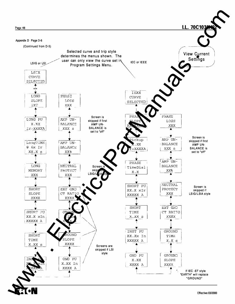
Page 48
Appendix D Page D-6
(Cont inued from 0·5)
S e lected cu rve a n d t r i p sty l e dete rmines the me n u s s h ow n . The
l.l. 70C1036H02
-----
-·-
\ LS IG or�
P rogram Sett ings M e n u . . � · � user can on ly view the cu rve set i�EC or I E E E
.---·-�J 1 LSIX ' CURVE l.§ELECTED
ew C u rre n t I � .. Sett i n g s )
--, VIEW
__L_
!LON�"' I � �r: \ LONG PU I · x . xx I I �XXXXA , L'j_-r-angTiME 1,' I @ 6x Ir , ' xx . x s i
�JG-, I MEMORY I LXXX ··-·
� . .. SHORT I SLOPE
ISHOR\ PU'
I XX . X xin XXXXX A
� I SHORT TIME L x . xx s
I IN} PU] 1 XX . X xin 1 • XXXXX A ' , ___ + __
Screen is skipped if first
A M P U N BALA N C E i s
set t o "off"
Screen is skipped if
LSIG/LS IA style
\ I
G���:I \ . �1� �\
GROUND 1 // SLOPE 1
XXXX Screens are f I skipped if LSI
[GNDt_ PU -l. I
style
x . xx In 1 XXXX A I �--
I EXX CURVE 1
1 SELECT�]2_] --.-----
_ _ 1 __ _ f PHASE i
I SLOPE I , XXXXXXX 1 _, __ t __ _
y Pickup I x . xx
j Ir=
y
XXA j
I PHASE i I TimeDial [ 1 x . x
SHORT PU 'I XX . X xir XXXXX A ��r--
• I SHORT I i TIME ' ��� i INST PU 'l XX . XX In XXXXX A ,
I GND PU x . xx
XXXX A
! BALANCE
I lAMP UN---=-l I BALANCE I 1 XX% ______j
INEUTL I . PROTECT
J'
XXX L __ r __
iEXT +GND I lCT f'o i I GROUND i
UtJ lGRO�D 1 l SLOPE 1
_2{XX:-__j
Screen is skipped if first
A M P U NBALA N C E is
set to "off"
Screen i s skipped i f
LS IG/LSIA style
i If I EC -EF style
'------ -------�
'EARTH" wi l l replace " G R O U N D"
Effective 03/2000 www . El
ectric
alPar
tMan
uals
. com

I.L. 70C1036H02
(Continued from D-5)
IA IB I C
xxxxxx
vt ...
I N I G
XXX
! L - L
VOLTAGE
XXX
! POWER
Fwd kw
XXX
! kVA
XXX
! • kvar
XXX
! DEMAND
Fwd kW
XXX
! DEMAND
Max kW
XXX
i
Effective 03/2000
� I N I G
AVERAGE
XXX
! I A I B I C
AVERAGE
XXX
! PF H z
XXX
! kVAh
XXX
! ENERGY
Rev kWh
XXX
! ENERGY
kWh
XXX
! DEMAND
Max kVA
XXX
! DEMAND
kVA
XXX
i
� IA I B I C
Max rms
XXX
! I N I G
Max rms
XXX
! I A I B I C
Min rms
XXX
! I N I G
Min rms
XXX
! PF
Min/Max XXX
! O P COUNT
XXX
Page 49
Appendix D Page D-7
V i ew D i sp lay S ett i n g s
www . El
ectric
alPar
tMan
uals
. com

Page 50
Appendix D Page D-8
(Cont inued from D-5)
I IRELAY ex ·
X : • * • (asterisk) Is placed beside the relay letter when at least one of its RELAY functions is E N A B L E D .
I RBLA; AX I "' RELAY BX
ENABLED VIEW
[RELAY [RELAY RELAY
BX ex AX
ENABLED PULSE
xxxx
kVAh kWh
S e l ected R e l ay d e t e rm i n es G ro u p s d isp layed.
B.e.J..ay A ( A l a rm i n g }
B ( B l ocki n g } C (Latch ing}
G r o ups D ispl ayed 1 , 2 P U L S E I N I T I ATE D I SA B L E D N o n e P U L S E I N I T I ATE E N A B L E D 1 1
l.l. 70C1036H02
V i ew A u x i l i a ry R e l ay M e n u
Effective 03/2000 www . El
ectric
alPar
tMan
uals
. com

I .L. 70C1036H02
(Continued from 0·5)
Effective 03/2000
VIEW
NEUT AM P
ALARM
XXXX A :
HighLOAD
TIME
ALARM
X . XX xir
OP COUNT
ALARM
XXX XX
ALARM TO
Event LOG
xxxxxxxx
THD
ALARM
XX %
ALARM
x . xx
kW
DEMAND
XXX XX XX
DEMAND
XXX XXX X
Page 51
Appendix D Page D-9
View A l a r m s
Non-Selectable Alarm
WATCHDOG
ALARM
SETTINGS
ERROR
ALARM
E EROM
ALARM
The message LDPU indicates an overload condition. This term is used for a Pickup
alarm on LSI, I E E E or I EC protection curves.
I f IEC ·EF style ' EARTH' will re place
' G R O U N D '
www . El
ectric
alPar
tMan
uals
. com

Page 52
AJ�pendix D Page D·1 0
(Cont i n u e d from D·S)
"XXXXXXXX =
xxxxx xxx II
N O S E TT I N G S I f no re lay functions a re enab led
D I G I TA L OUTPUT I f any re lay funct ions a re e n a b l e d
Save (Page 0· 19)
~ ADDR 0 1 xxxxxxxx �-------.
1 xxxxxxxxj
' IADDR 0 3 · XXXXXXXX i xxxxxxxxj
'
r ADDR 0 4 xxxxxxxx xxxxxxxx
RLY FUNC · 1------� 1 DODD
SEL
I.L. 70C1036H02
V i ew Access o ry B u s Sett i n g s
E ac h of the 4 addresses is a seJ�arate Save g roup
O F F A U X B E LL D E A D A L A R M W A T C H
Effective 0312000 www . El
ectric
alPar
tMan
uals
. com
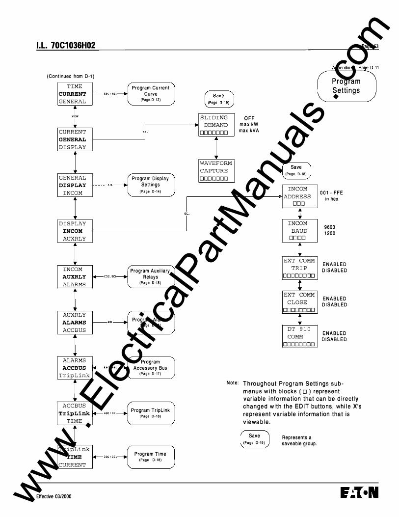
I .L. 70C1036H02
(Continued from D-1 ) T IME
CURRENT ESC I SEC
GENERAL
VIEW
� CURRENT
GENERAL D I S PLAY
GENERAL
DISPLAY -SEL
IN COM
D I S PLAY
INC OM AUXRLY
IN COM
AUXRLY �ESC /SEL---...j ALARMS
AUXRLY
ALARMS -SEL--------1 ACCBUS
ALARMS
ACCBUS � ESC / SE� TripLink
ACCBUS
TripLink �ESC I SEL----+1 TIME
T r i pL i nk
TIME � ESC f SEL----+j CURRENT
Effective 03/2000
Program Current Curve
(Page D- 12)
sL I
Program Display Settings
(Page D-14)
Program Auxil iary Relays
(Page D-15)
Program Alarms (Page D-16)
Program Accessory Bus
(Page D- 17)
Program TripLink (Page D-18)
Prog ram Time (Page D-18)
J J I
J
S L I D ING
DEMAND
0000000
WAVEFORM
CAPTURE
DDCIDIJDD
Note:
OFF max kW max kVA
Save (Page D-18)
INC OM
ADDRES S
DDIJ
IN COM
BAUD
0[100
EXT COMM
TRI P
[IDITI[I[IIJO
EXT COMM
CLOSE
00000000
DT 9 1 0 COMM
00000000
P rog ra m S etti n g s
0 0 1 - FFE in hex
9600 1 200
ENABLED D ISABLED
ENABLED D ISABLED
ENABLED D ISABLED
T h ro u g h o u t P rog ram S etti ngs s u b
m e n u s w i t h b l ocks ( o ) represent var iable i nformation that can be d i rect ly
c h a n g e d with t h e E D I T butto n s , wh i l e X's
re pres e n t var iab le i nformation that is
v i e wa b l e .
Save (Page D-19)
Represents a saveable group.
Page 53
www . El
ectric
alPar
tMan
uals
. com

Page 54
Appendix D Page D-12
(Cont i n ued from D - 1 1 )
! IEEE xx L· � 1 Ls:tG xx •• ,.J Ls;8��e::·;�e 1 l __ ,---J l (Pag• o-13)
VIEW
M O O I N V V E R Y I NV
E XT I N V
0 .40 - 1 .0 0 (steps o f 0 .05)
M O D I N V V E R Y I N V
E XT I NV
0 . 1 - 5 .0 0 .2 - 5 .0 0 .2 - 5.0
M 1 = 1 4 x or = 1 2x or = 1 0 x
Screen is skipped i f LS I c u rve is
se lected .
(steps of 0 . 1 )
1 .5 - 1 0 .0 (steps of 0 . 5)
(and sett ing M 1 )
HORT PU D . D xir . XXXX A
i lsi1tiiT-i
0 . 1 0 - 0 .50 1 TIME (steps of 0 .05) : D . DO s l ___ • __ _j
_ ____1__. 2 . 0 _ M 1 �INST PU i
O F F • DD .Dx In I (steps of 0 .5) XXXXX
I E E E 0.24 - 1 .00 x In or x Ext G N D CT (steps of 0 .0 1 )
1 1 1 E C · E F \_ Catalo
.-=-g
�#
_ __/
i iEC XX I '"-: LS.Gt XX I
I EC -A I EC - B I EC-C
VIEW
I EC-A 0 .05 - 1 .00 I EC - B 0 . 1 0 - 1 .00 I E C-C 0.20 - 1 .00
(steps of 0 .05)
IEC 0 . 1 0 - 1 .00 x l n or x Ext G N D CT (steps of 0.0 1 ) and OFF setting
l.l. 70C1036H02
XX = Represents the active curve .
'ON' or left blank, automatically. (Not ed itable . ) Set to " ON' if setti ngs are saved with in that curve. O n l y one 'ON' at a t ime .
i AMP I
: BALANCE J L-r-1 NEUTRAL I
I PRW;CT I DOD % .
I
rGRo*UNDl. SLOPE 1 . [JDDD I
1 to 30 s O FF
(steps of 1 s)
Scre e n is 0 - 240 s skipped if first
(steps of 1 s) A M P U N -BALANC E is s e t
to ' OF F"
5 % - 25% O F F
(steps o f 1 %)
50% 1 00 %
Scree n is sk ipped i f LSIG
factory style
none none denotes 1 00011 default 80011\ to In value i,!j,�: $"''"' '"
Skipped if LS I
(steps of
7 factory style 0 . 1 0 -
FLAT 12T
• I f I E C ·EF style " E ARTH' wi l l
replace " G R O U N D '
Effective 0312000 www . El
ectric
alPar
tMan
uals
. com

l.l. 70C1036H02
(Cont in u ed from 0·1 2)
2 4
0.40 - 1 . 00 (steps of 0 .05)
I f LONG S L O P E = 12T:
2.0 . 24.0 (steps of 0 .5)
M 1 = 1 4x o r = 1 2x o r
1 0x
Effective 03/2000
14T: 1 .0 - 5 . 0
(steps of 0 . 5 )
O N O F F
F L A T 1 2 T
1 . 5 - 1 0 (steps of 0 .5 ) (and sett ing
M 1 x l n )
0 . 1 0 - 0 .50 (steps o f 0 .05)
2 . 0 • M1 O F F
(steps of 0.5)
LONG
SLOPE
ID T
vt LONG PU
D .D I r=XXXXA
1 LongTIME
@ 6x I r
DD . D s
! LONG
MEMORY
ODD
1 SHORT
SLOPE
DODD
1 SHORT PU
DD. D xir XXXXX A
1 SHORT
TIME
D .DD s
1 INST PU
[10.0 xin
xxxxx A
i
PHASE
LOSS
DOD
1 AMP UN-
BALANCE
ODD s
1 AMP UN -
BALANCE
DD%
1 NEUTRAL
PROTECT
DODD
r EXT GND
CT RATIO
DDDDD
1 GROUND
TIME
D .DD s
t GROUND
SLOPE
DODD
1 GND PU
D. DO xxxx A
1
1 30 s O F F
(steps o f 1 s)
0 - 240 s (steps of 1 s)
5% 25% O F F
(steps o f 1 % )
5 0 % 1 00%
Page 55
Appendix D Page D-13
Prog ram L S I - G C u rve
Screen is s kipped i f f i rst A M P U N
BALANCE is set t o " O F F "
( S e e Sect ion 4 .2 .2)
Screen is sk ipped if LS IG factory sty le
none 1 000/1 800/1 400/1 20011 1 00/1 1 0/1
none d enotes delaul t to I n value
FLAT 12T
Screens are skipped if LSI style
0 . 1 0 - 1 .00 and OFF ( I EC style only) 0 .24 - 1 .0 0 ( I E E E) with 1 200A Max (steps of 0 .0 1 )
I f I EC - E F style " EARTH" wi l l replace
' G R O U N D "
www . El
ectric
alPar
tMan
uals
. com

Page 56
Appendix D Page D-14
(Continued from 0- 1 1 )
I IA IB IC I A U TO
M A N U A L I =too ! VIEW
O N O F F
/ Al l d isplay screens except
the first use "ON" or 'OFF'.
� 0
� kvar
DEMAND
IN I G
IA I B IC
AVERAGE
ODD
PF Hz
DOD
ENERGY
kWh ODD
DEMAND
Max kVA
DOD
l .l. 70C1036H02
Max rms
IN I G
Max rms DOD
P ro g r a m D i s p l a y
S et t i n g s
IA I B I C Min rms
IN I G
Min rms DOD
Min /Max ODD
O P COUNT
ODD
Effective 0312000 www . El
ectric
alPar
tMan
uals
. com

I.L. 70C1036H02
(Continued from D-1 1 )
X = " • " (asterisk) is placed beside the relay Jetter when at least one of itsTR IP or / ALARM functions is ENABLED . G�
Save (Page D-19)
_JI�����TE l� ���B_L_E_D,--�
RE��� X
RELAY BX . DDDDDDDD 1 DDDDDDDD
RELAY AX
ENABLED
ENABLED
PULSE kVAh kWh
Selected R e l a y d ete rmines Groups d i sp l ay e d .
R e l ay A (Alarming)
B (B lock ing) c ( Latc h i ng )
Effective 03/2000
G roups D i splayed 1 , 2 P U L S E I N I T I AT E D I SA B L E D N o n e P U LS E I N I T I ATE E N A B L E D 1 1
If IEC -EF style " EARTH' wi l l replace
'GROU ND'
RELAY X
S DT
DDDDDDDD _l rRELAYXl
• INST • · oooooooc •
GND TRI P l googgooo 1 t
, - '!'_________, "ENABLED" or • RELAY X . "D ISABLED" for AmpUNBAL
DDDDDD::::C :
RELAY X
PlugTR I P
DDDDDDDD
RELAY X
C omrnTRI P
DDDDDDDD
1 ACC TRI P
ooooo=oo
al l screens
Page 57
Appendix D Page D-15
� Rel ays Men�
G roup 2
RELAY X
kVA DMND
kW DMND
DDDDDDDD
RELAY X
RELAY X
H ighLOAD
DDDDDDDD
RELAY X
LDPU
DDDDDDDD
RELAY X
NeutALRM
DDDDDDDD
IRELAt X I
· ���=��� · •
www . El
ectric
alPar
tMan
uals
. com
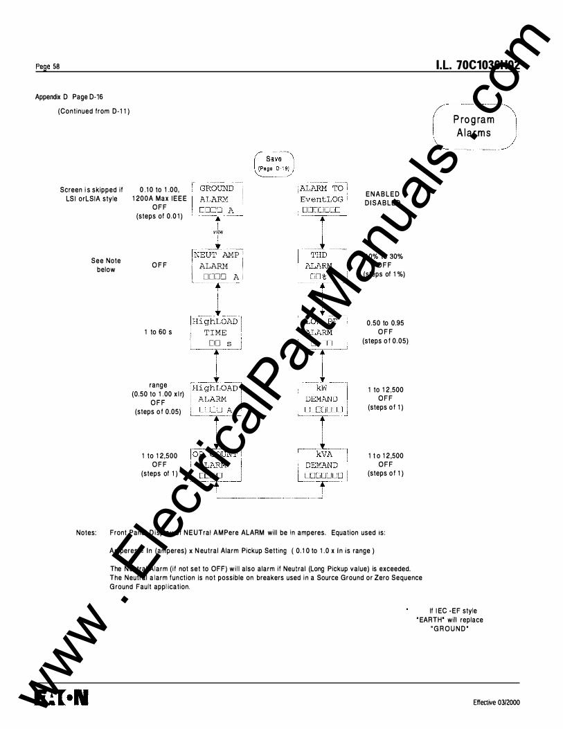
Page 58 I.L. 70C1036H02
Appendix D Page D-16
(Continued from D - 1 1 ) P ro g ra m A l a r m s
Screen i s skipped if LSI orLSIA style
See Note below
0 . 1 0 to 1 .00, 1 200A Max I E E E
O F F (steps of 0.0 1 )
O F F
1 to 60 s
range (0.50 to 1 .00 x l r)
O F F (steps o f 0.05)
1 to 1 2,500 O F F
(steps of 1 )
fN _l � INEUT AMP 1
l A��� J
�{glAD ] 1 TIME . [10 s .
, 1 -Hi ghLOAD I
E N A B L E D D I S A B L E D
1 0% to 30% O F F
(steps of 1 %)
0.50 to 0.95 O F F
(steps o f 0.05)
1 to 1 2 ,500 O F F
(steps o f 1 )
1 t o 1 2 ,500 O F F
(steps o f 1 )
Notes: Front Panel D i splay of N E UTral AMPere ALARM will be in amperes. Equation used is:
Amperes = In (amperes) x N eutral Alarm Pickup Setting ( 0. 1 0 to 1 .0 x I n is range )
The N eutral Alarm (if not set to OFF) wi l l also alarm if Neutral (Long Pickup value) is exceeded. The Neutral a larm function Is not possible on breakers used i n a Source Ground or Zero Sequence Ground Fault appl ication.
If I EC -EF style ' EARTH' will replace
" G R O U N D '
Effective 0 3/2000 www . El
ectric
alPar
tMan
uals
. com
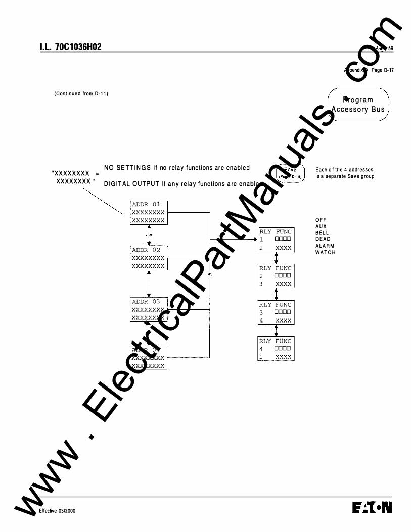
I.L. 70C1036H02
(Continued from D-1 1 )
·xxxxxxxx =
N O S E TT I N G S I f no relay functions are enabled
XXXXXXXX • D I G IT A L O U T P U T I f a n y re lay functions a re e nab led
~ ADDR 0 1 xxxxxxxx xxxxxxxx
t RLY FUNC
1 DODD
ADDR 0 2 2 xxxx
xxxxxxxx l xxxxxxxx RLY FUNC
j SEL 2 DODO 3 xxxx
r t ADDR 0 3
RLY FUNC xxxxxxxx 3 DODO xxxxxxxx 4 xxxx
j
l .. RLY FUNC
ADDR 0 4 4 DODO xxxxxxxx 1 xxxx xxxxxxxx
Effective 03/2000
Page 59
Appendix D Page D-17
P ro g r a m Accessory B u s
Each o f the 4 addresses Is a separate Save g roup
OFF AUX BELL DEAD ALARM WATC H
www . El
ectric
alPar
tMan
uals
. com
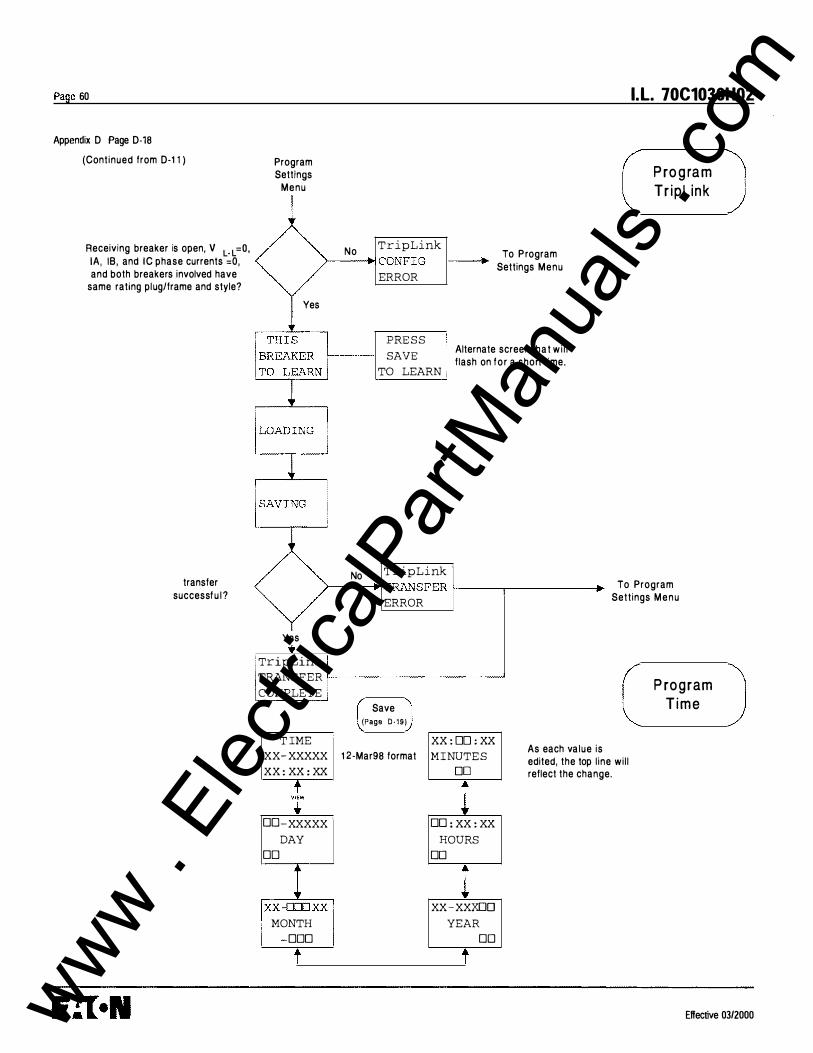
Page 60
Appendix D Page D-18
(Cont inued from D-1 1 )
Receiving breaker is open, V L- L =0, lA , IB, and IC phase currents =0, and both breakers involved have
same rating plug/frame and style?
transfer successf u l ?
Program Settings
Menu
No TripLink >------i"' CONFIG
ERROR
Yes
� ' '
No
PRE S S SAVE
TO LEARN i
TripLink
To Program Settings Menu
Alternate screen that w i l l f lash on for a short t ime.
I.L. 70C1036H02
P ro g ra m Tr ipl ink
>----+ TRANSFER 1-------,---------. ERROR
To Program Sett ings M e n u
Yes
, TripLink TRANSFER 1--------------'
COMPLETE '
T IME
Save (Page D- 19)
xx- xxxxx 1 2-Mar98 format
XX : XX : XX
t v•EW
DD-xxxxx ·
DAY DO
MONTH DOD
XX : OO : XX
M I NUTE S DO
DD : XX : XX
HOURS DO
xx-xxxoo
YEAR DO
As each va lue is edited, the top l ine wi l l reflect the change.
P ro g ram T i m e
Effective 03/2000 www . El
ectric
alPar
tMan
uals
. com

I.L. 70C1036H02
(Cont inued from D-1 1 )
Previous Menu Level
i (AUTOi
S ETTINGS
TRAN SFER
COMPLETE
YES
SAVE
xxxxxxxx XXX XX XXX
Effective 03/2000
Save
l S ETTING S Savable TRANSFER Data ERROR Screen
+ N O
}If-ESC 0
J
Page 61
Appendix D Page D-19
S av e
R (TIMEOU SAVE
SAVE---ll'! XXXXXXXX xxxxxxxx
r.------� SAVING . . �--- ------�
Transfer successfu l?
SAVE SAVE
I EEE I EC
GROUP ? GROUP ?
SAVE SAVE
DI S PLAY INC OM
GROU P ? GROUP ?
SAVE SAVE
RELAY B ? RELAY C ?
GROU P ? GROUP ?
www . El
ectric
alPar
tMan
uals
. com

Page 62
Appendix D Page D-20
(Continued from D- 1 )
NOT E : I f LSI cu rve is se lected GND TEST wi l l not be ava i lable
I PH TEST
GND TEST
GND TEST 0 . 1 to 2.0
(steps of 0 . 1 )
P H T E S T I ' CURRENT '
Lxxxxx .... JU
I.L. 70C1036H02
Test M e n u
I f I E C - E F style " E ARTH' will replace
' G R O U N D '
Effective 03/2000 www . El
ectric
alPar
tMan
uals
. com
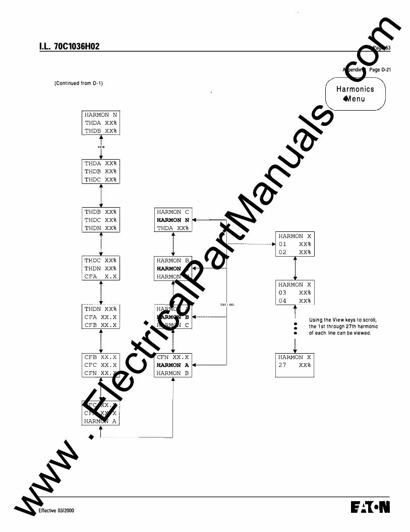
I.L. 70C1036H02
(Continued from D-1 )
Effective 03/2000
HARMON N
THDA XX% THDB XX%
t VIEW
� THDA XX% THDB XX% THDC XX%
THDB XX% THDC XX% THDN XX%
I THDC XX% THDN XX% C FA x . x
THDN XX% C FA XX . X CFB XX . X
CFB xx . x C F C xx . x
C FN xx . x
CFC XX . X C FN XX . X HARMON A
HARMON C
HARMON N THDA XX%
HARMON B
HARMON c HARMON N
HARMON A
HARMON B HARMON c
CFN XX . X HARMON A HARMON B
ESC I SEL
HARMON X 0 1 XX% 0 2 XX%
HARMON X 0 3 XX% 0 4 XX%
Page 63
Appendix 0 Page D-21
H a r m o n ics M e n u
T Usi ng the View keys to scroll, 1 st through 27th harmonic
each line can be viewed. • the • • of
l HARMON X 2 7 XX%
www . El
ectric
alPar
tMan
uals
. com
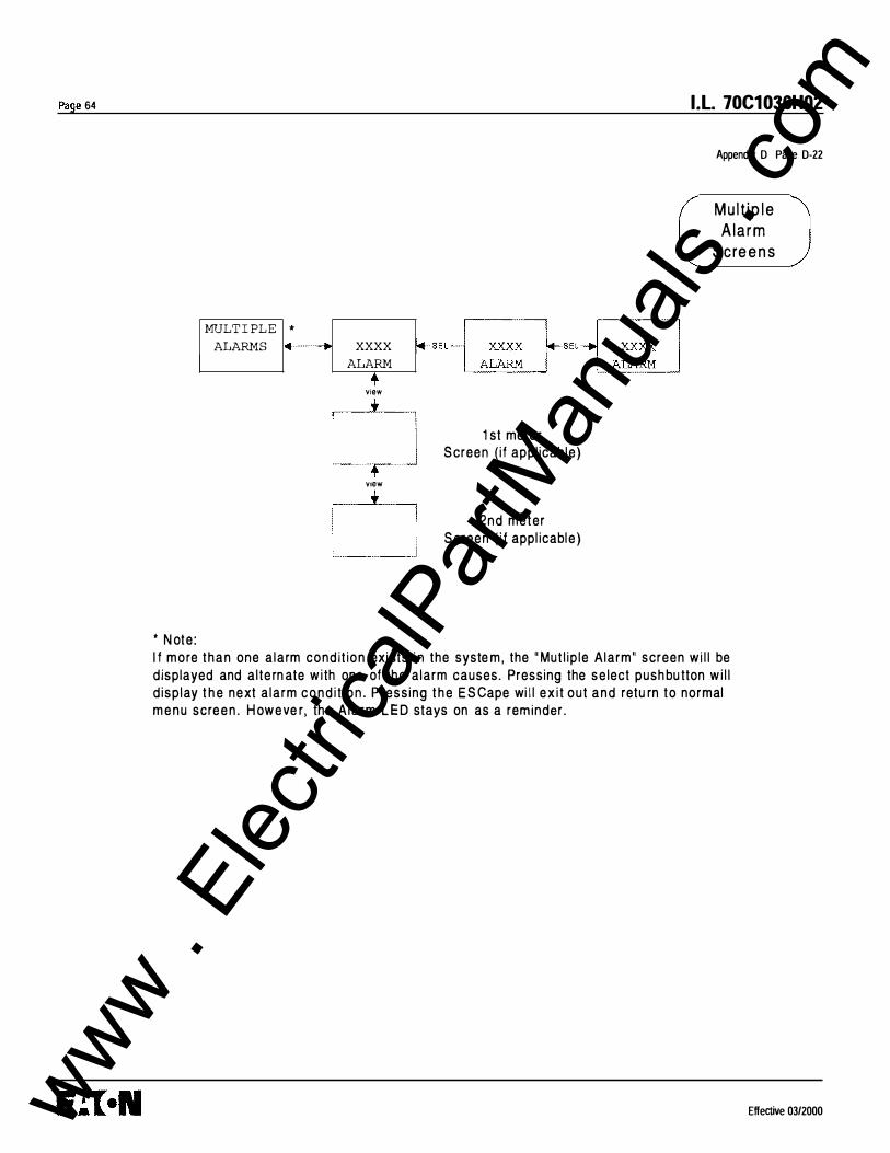
Page 64
MULT I PL E *
ALARMS xxxx
ALARM
+ view
V1SW
• N ote :
f+-SEL- ��-SEL -� � � 1 st mete r
Screen ( i f appl icable)
2nd meter Screen ( i f appl icabl e )
I .L. 70C1036H02
Appendix D Page D-22
M u l t i p l e A l a r m
S c re e n s
I f more than one a larm condi t ion exi sts i n the syste m , the " Mut l ip le A larm" screen w i l l be displayed and a l te rn ate w i th one of t h e a larm causes. Pressing the s e lect push bu tton w i l l d isp lay t h e next a larm c o n d i t i o n . P ress ing t h e E S Cape wi l l e x i t out a n d retu rn to normal m e n u scre e n . H oweve r , the A l a r m L E D stays on as a reminder.
Effective 03/2000 www . El
ectric
alPar
tMan
uals
. com

I .L. 70C1036H02
Appendix D Page D-23
LSIG ON
LSIG C u rrent C u rv e
L O N G S L O P E 1 2 T
L O N G P U 1 . 00
LO N G T I M E 4.0 s
L O N G M E M OR Y O N
S H O RT S LO P E F LAT
S H O R T PU 3.0
S H O RT T I M E 0 .30 s
I N ST P U 4 . 0
G R O U N D P U ** 0 . 402
G R O U N D S L O P E** .. FLAT
G R O U N D T I M E**** 0 .30 s
EXT G N D C T RATIO" none
N E U T R AL P R O T E C T ' 1 0 0 %
AM P U N B A L A N C E O F F
A M P U NBAL A N C E ( t i m e ) 1 0 s
I E E E C u rve I E C C u rve
P H A S E S L O P E M OD I N V P HA S E S L O P E
P ic k u p 1 .00 P ickup
PHASE T i m e D i a l 2 .0 P HASE T i m e D i a l
S H O R T P U 3.0 S HO R T P U
S H O R T T I M E 0 .30 s S HO R T T I M E
I N S T P U 4 . 0 I N ST P U
G RO U N D P U " 0 . 402 E A R T H P U * *
G R O U N D S L O P E" * * FLAT E A R T H S L O P E " * *
G R O U N D T I M E" " 0.30 s E A R T H T I M E " "
E XT G N D CT RATIO" none EXT EARTH CT RATIO"
N E U T R A L P R OT E C T ' 1 00 % N E U T R A L P R OT E CT '
A M P U N BA L A N C E O F F A M P U N B A L A N C E
A M P U N BALA N C E ( t ime) 1 0 s A M P U N BA L A N C E ( t i m e )
P H A S E L O S S O F F P HA S E LOSS
• Applicable on 1 1 L S I o r 1 1 1EC factory styles on ly • • App l i cable on 1 1 LS IG, 1 1 LS IA and 1 1 1 E C - E F
Page 65
Facto ry Setti ngs
I E C - A
1 .00
0 .20
3 .0
0 .30 s
4.0
0 .40
F LAT
0 .30 s
none
1 00 %
O F F
1 0 s
O F F
P H A S E L O S S
D I S P LAY (6 active)
O F F ••• Only avai lable o n L S I G , LSI , LSIA C u rrent Curve. O n I E E E c u rve and I EC c u rve, LONG M E MORY and S H OR T 12T SLOPE sett i n g s are n ot available.
lA IB I C I N I G L - L VOLTAG E Fwd Power P F HZ E N E R GY F W D & R E V (all others)
A U TO O N O N O N O N O N O F F
AuxReLaYs
A L A R M S
A C C B U S Switch relays O F F
G E N E RA L
A l l relays D IS A B L E D
Al l a l a r m s O F F 1
Add ress 1 Re lay 1 is Aux.-Aux Al l other addresses and
F I X E D D E M A N D 1 5 M i n w i n do w WA V E F O R M C A P T U R E O F F
1 . Except LSIA w i l l have Gro u n d Alarm o n @ .40x 2. P l u g rat i n g s 3200, 4000, 5000, 6300 A are set to .24
Effective 03/2000
•u• Appl icable on 1 1 L S I G , 1 1 1 E C- E F
I N C OM
I N C O M A D D R ESS 1 00 hex
I N C O M B A U D RATE 9600
EXT C O M M T R I P E NA B L E D
E X T C O M M C LO S E E N A B L E D
D T 9 1 0 C O M M D I SA B L E D
T E ST
P H T E ST 0.4x I n
G N D T EST 0 . 1 x I n
www . El
ectric
alPar
tMan
uals
. com
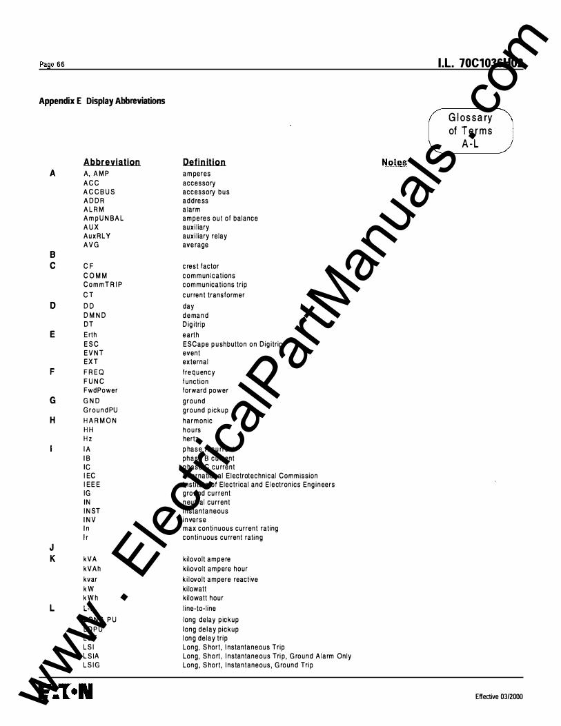
Page 66
Appendix E Display Abbreviations
A
B c
D
E
F
G
H
J K
L
Abbreviation A, AMP ACC ACCBUS ADDR A LRM AmpUN BAL AUX AuxRLY AVG
C F COMM CommT R I P C T D O D M N D DT Erth ESC EVNT EXT F R EQ F U NC Fwd Power G N D GroundPU HARMON HH H z lA I B IC I EC I EE E IG IN I N ST I N V I n l r
kVA kVAh kvar kW kWh L· L LONG PU LDPU L OT LS I LS I A LS IG
Defin ition amperes accessory accessory bus address a larm amperes out of balance auxi l iary auxi liary relay ave rage
c rest factor communicat ions communications trip current transformer day demand D ig itrip earth ESCape p ushbutton on Dig itrip event external frequency function forward power ground ground pickup harmonic hou rs hertz p hase A cu rrent phase B cu rrent p hase C cu rrent I nternational E lectrotechnical Commission I nstitute of Electrical and Electronics Eng ineers ground cu rrent neutral current i nstantaneous inverse max conti nuous current rating cont inuous current rating
kilovolt ampere kilovolt ampere hour k i lovolt ampere reactive ki lowatt kilowatt hour l ine-to-line long delay p ickup long delay pickup l ong delay tr ip Long, Short, I nstantaneous Trip Long, Short , I nstantaneous Tri p , G round Alarm Only Long , Short, I nstantaneous, G round Trip
Notes
I.L. 70C1036H02
G l os s a ry of T e r m s
A - L
Effective 03/2000 www . El
ectric
alPar
tMan
uals
. com

I.L. 70C1036H02
Abbreviation M Max
M i n M I N M M
M m m
N N E U T NeutALRM
0 O P OverTE M P
p P F P G M P H P I C K U P P l ugTR I P P R OTECT P U
Q R R EV
Rev Rev Power R LY rms
s s S O T S E L S ET S ETT INGS ss
T T E M P T H O
u U NBAL
v v VAB V B C VCA V E R
w X y y y z
E flective 03/2000
Definition m aximu m m i ni m u m m i n ute m in utes
m onth
neutra l neutral alarm
operation over temperature
power factor program phase pickup rating plug trip protection p ickup
revision reverse reverse power relay root-mean-squared
seconds short delay trip SELect pushbutton on O igitrip settings setting seconds
temperature total harmonic distortion
unbalance
volts l ine voltage from phase A to phase B l ine voltage from phase B to phase C l ine voltage from phase C to phase A version
year
Also known as Long PU a n d LOPU
G l o s s a ry of Terms
M - Z
Page 67
www . El
ectric
alPar
tMan
uals
. com
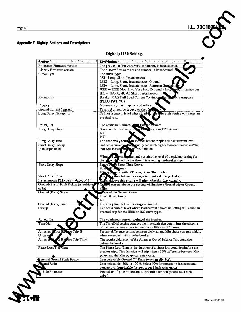
Page 68 I.L. 70C1036H02
Appendix F Digitrip Settings and Descriptions
Digitrip 1150 Settings
8\!ttiu . ·· : . \ .\ i> .· ' ·· c h :ooen�JtiQn· > •. .. · ··· . • • •• / < . ·. { . ..• ,; > . \> .. · Protection Firmware version The protection firmware version number, in hexadecimal. Display Firmware version The display firmware version number, in hexadecimal. Curve Type The curve type:
LSI Long, Short, Instantaneous LSIG Long, Short, Instantaneous, Ground LSIA Long, Short, Instantaneous, Alarm on Groond only IEEE (IEEE Mod. Inv., Very Inv., Extremely Inv.) Short, Instantaneous IEC - (IEC-A, -B, -C) Short, Instantaneous
Rating (In) Breaker MAX Full Load Current Continuous Rating (In) in Amperes (PLUG RATING).
Frequency Measured system frequency of voltage. Ground Current Sensing Source ground or Zero Sequence. Long Delay Pickup Ir Defines a current level where load current above this setting will cause an
eventual trip.
Rating (lr) The continuous current setting of the breaker. Long Delay Slope Shape of the inverse-time-over-current (LongTIME) curve:
I2T 14T
Long Delay Time The time delay setting in seconds before tripping @ 6xlr current level. Short Delay Pickup Defines a current setting usually set much higher than continuous current (a multiple of lr) that will initiate timing of this function.
When the current reaches and sustains the level of the pickup setting for the period defined by the Short Time setting, the breaker trips.
Short Delay Slope Shape of the Short Time Curve. FLAT (fixed time) 12T (applicable with 12T Long Delay Slope only)
Short Delay Time The delay time before tripping after short delay is picked up. Instantaneous Pickup (a multiple of In) Current above this setting will trip the breaker immediately. Ground (Earth) Fault Pickup (a multiple Ground current above this setting will initiate a Ground trip or Ground I of ln) alarm. Ground (Earth) Slope Shape of the Ground Curve: I FLAT (fixed time)
12T Ground (Earth) Time The delay time before tripping on Ground. Pickup Defines a current level where load current above this setting will cause an
eventual trip for the IEEE or IEC curve types.
Rating (lr) The continuous current setting of the breaker. Time Dial The TimeDial setting controls the time scale that determines the tripping
of the inverse time characteristic for an IEEE or IEC curve. Amperes Out of Balance Trip % Percent difference setting between the Max and Min phase currents which, Unbalance when exceeded, will trip the breaker. Amperes Out of B alance Trip Time The required duration of the Amperes Out of Balance Trip condition
before the breaker trips. Phase Loss Trip Time The Phase Loss Time is the duration of a phase loss condition before the
breaker trips. This function will trip when a 75% difference between Max phase and the Min phase currents exists.
External Ground Scale Factor User selectable Ground CT Ratio (when applicable). Neutral Ratio User selectable. SO% or 100%. Select 50% for protecting If2 size neutral
conductors. (Applicable for non-ground fault units only.) 4 m Pole Protection Neutral or 4m pole protection. (Applicable for non-ground fault style
units.)
Effective 03/2000 www . El
ectric
alPar
tMan
uals
. com
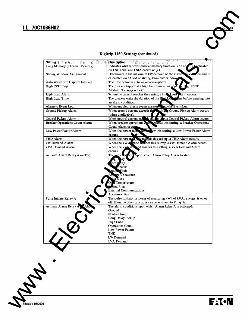
I .L. 70C1036H02 Page 69
Digitrip 1150 Settings (continued)
Setting Description Long Memory (Thermal Memory) Indicates whether over-current memory function is on or off. (Applicable
on LSI, LSIG and LSIA curves only.) Sliding Window Assignment Determines if the maximum kW demand or the maximum kVA demand is
calculated on a fixed or sliding 15-minute window. Auto Waveform Capture Interval The time between auto waveform captures. High INST Trip The breaker tripped at a high fault current via separate High INST
Module. See Appendix C. High Load Alarm When the current reaches the setting, a High Load Alarm occurs. High Load Time The breaker waits the duration of the High Load Time before entering into
an alarm condition. Alarm to Event Log When enabled, alarm events are stored into the Event Log. Ground Pickup Alarm When ground current exceeds this setting, a Ground Pickup Alarm occurs
(when applicable). Neutral Pickup Alarm When neutral current exceeds this setting, a Neutral Pickup Alarm occurs. Breaker Operations Count Alarm When breaker operations count exceeds this setting, a Breaker Operations
Count Alarm occurs. Low Power Factor Alarm When the power factor falls below this setting, a Low Power Factor Alarm
occurs. THD Alarm When the percent THD exceeds this setting, a THD Alarm occurs. kW Demand Alarm When the kW demand reaches this setting, a kW Demand Alarm occurs. kVA Demand Alarm When the kV A demand reaches this setting, a kV A Demand Alarm
occurs. Activate Alarm Relay A on Trip The trip conditions upon which Alarm Relay A is activated:
Long Delay Short Delay Instantaneous Ground Fault Ampere Unbalance Phase Loss Over Temperature Rating Plug External Communications Accessory Bus
Pulse Initiate Relay A The pulse initiator, a means of measuring kWh of kV Ah energy, is on or off. If on, no other functions can be assigned to Relay A.
Activate Alarm Relay A on Alarm The alarm conditions upon which Alarm Relay A is activated: Ground Neutral Amp Long Delay Pickup High Load Operations Count Low Power Factor THD kW Demand kVA Demand
Effective 03/2000 www . El
ectric
alPar
tMan
uals
. com

Page 70 l.l. 70C1036H02
Digitrip 1 150 Settings (continued)
,seftimi '' ··' :·.: .. · .. · . . · ··· .. .. j · " . ) · ··.' . . .. lWmmi11n ·· : .. . •... ·· .. ..•.. · .·• . · ; :., .. ···••··.· . Jdl ·> · •.. ;.:. ;, .• :;, · · : .. Activate Block Close Relay B on Trip The trip conditions upon which Block Oose Relay B is activated:
Long Delay Short Delay Instantaneous Ground Fault Ampere Unbalance Phase Loss Over Temperature Rating Plug External Communications Accessory B us (when applicable)
Activate Latch Relay C on Trip The trip conditions upon which Latch Relay C is activated: Long Delay Short Delay Instantaneous Ground Fault Ampere Unbalance Phase Loss Over Temperature Rating Plug External Communications Accessory Bus (when applicable)
Return to Metered Current Display When set to Automatic, returns the trip unit display to the metered phase A, B and C current screen if the unit keypad is idle for 5 minutes.
INCOM Address Communication address 00 I through FFE.
Effective 03/2000 www . El
ectric
alPar
tMan
uals
. com

I.L. 70C1036H02
Appendix G Auxiliary Relays
Available Input Voltage for
8 g ! l= I ®# @ POWER RElAY MODU...E
DIGITRIP 1150
MAGNUM BREAKER
@ Style Number
Power I Relay Module
120 VAC +I - 1 0% 70C1002G01
230 VAC +1- 10% 70C1002G02
24148 VDC + 1 - 10% 70C1005G01
Notes: 1 . This relay contact Is programmed via Digtbip 1 1 50 as Relay A. See Appendix 0..1 5. 2. This relay contact is programmed via Digtbip 1 1 50 as Relay B. Block Close will prohibit
the remote closing of the circuit breaker. 3. This relay contact is programmed via Digitrip 1 1 50 as Ralay C. This relay will hold contact
status on loss of Auxiliary Power. 4. Contact rating (resistive load)
AC 0.5A @230 VAC AC 1A @120 VAC DC 1A @48 VDC
5. Verify Input voltage rating before energizing circuH.
Effective 03/2000
Page 7 1
www . El
ectric
alPar
tMan
uals
. com

Page 72 I .L. 70C1036H02
Appendix H Accessory Bus Digital Output Modules
Control Voltage @
@
r;==:::::=::)<XX::n Al6 A1 7
N otes :
� D Magnum Breaker
UJ
l Dedicated local ne1work for each tvlagnum Breaker
(I) T h e D ig itr ip 1 1 50 fro n t p a n e l is use d to p rog ra m the e xte rna l m o d u le a n d can be p rog ra m m e d fo r R e l aY F U N C tion of A U X S w itc h o r B E L L A larm o r D EA D man o r W ATC H D O G o r A L A R M (th e A la r m relay tra c k s the fu n ctio n o f the A u x ReLaY A p ro g ra m m ing) fun ctio n s . S e e A p p e n d i x 0 - 1 7 .
® E ach m o d u le h a s 4 re lays . E a c h relay h a s a fo rm C c o ntact w it h e a c h h a v i ng a rat ing of 1 OA m a x @ 2 5 0 VA C .
® C o ntro l vo ltage i s 1 2 0 VAC ± 2 0 %
® Acce s s o ry B u s M o d u les use D I N rail m o u n t ing . C o n n ecto r ty p e s a re p l u g - i n -P h o e n i x . F o u r fo r m C co ntacts u se 1 2 p in co n n e cto rs . P o w e r is 5 p i n . C o m m u n icatio n is 3 p i n .
@ Ca b le i s C · H style 2 A 9 5 7 80 5 G 0 1 o r B e ld e n 9 4 6 3 c a b l e .
® Se t s w itch t o corre s p o n d in g a d d ress (0 0 1 th ro u g h 004) p ro g ra m m e d via the D ig itr ip front p a n e l . S e e A p p e n d ix D - 1 7.
IJ) Set s w itch u p to i n se rt 1 00 o h m te rm inat ing re s isto r on last relay of the n etwo rk.
Effective 03/2000 www . El
ectric
alPar
tMan
uals
. com
I .L. 70C1036H02
This instruction booklet is published solely for information purposes and should not be considered all inclusive. If further information is required, consult Cutler-Hammer, Inc.
The sale of the product shown in this literature is subject to the terms and conditions outlined in appropriate CutlerHammer, Inc., selling policies or other contractual agreements between the parties. This literature is not intended to and does not enlarge or add to any such contract. The sole source governing the rights and remedies of any purchaser of this equipment is the contract between the purchaser and Cutler-Hammer, Inc.
NO WARRANTIES, EXPRESSED OR IMPLIED, INCLUDING WARRANTIES OF FITNESS FOR A PARTICULAR PURPOSE OR MERCHANTABILITY, OR WARRANTIES ARISING FROM THE COURSE OF DEALING OR USAGE OF TRADE, ARE MADE REGARDING THE INFORMATION, RECOMMENDATIONS, AND DESCRIPTIONS CONTAINED HEREIN.
In no event will Cutler-Hammer, Inc., be responsible to the purchaser or user in contract, in tort (including negligence), strict liability, or otherwise for any special, indirect, incidental, or consequential damage or loss whatsoever, including, but not limited to, damage or loss of the use of equipment, plant or power system, cost of capital, loss of power, additional expenses in the use of existing power facilities, or claims against the purchaser or user by its customers resulting from the use of the information, recommendations, and descriptions contained herein.
Effective 03/2000
Page 73
www . El
ectric
alPar
tMan
uals
. com

Page 74 I.L. 70C1036H02
Effective 03/2000 www . El
ectric
alPar
tMan
uals
. com

www . El
ectric
alPar
tMan
uals
. com

I.L. 70C1036H02
Cutler-Hammer Pittsburgh, PA U.S.A.
Effective 03/2000
Printed in U.S.A.
Page 75
www . El
ectric
alPar
tMan
uals
. com