
Manual Concentrate Management System - Fire … Manual Concentrate Management System (CMS) provides...
12
1 Installation and Operation Manual INSTALLATION AND OPERATION MANUAL Manual Concentrate Management System with Automatic Flush Form 887 05/15 All quality FoamPro products are ruggedly designed, accurately machined, carefully assembled, thoroughly inspected and tested. In order to maintain the high quality of your unit, and to keep it in a ready condition, it is important to follow the instructions on care and operation. Proper use and good preventive maintenance will lengthen the life of your unit. ALWAYS INCLUDE THE UNIT SERIAL NUMBER IN CORRESPONDENCE. Unit Serial Number __________________________________ FoamPro • 26 Southern Blvd. • Nesconset, NY 11767 USA • 800-533-9511 • FAX 816-892-3178
Transcript of Manual Concentrate Management System - Fire … Manual Concentrate Management System (CMS) provides...

1
Installation and Operation Manual
INSTALLATION ANDOPERATION MANUAL
Manual ConcentrateManagement System
with Automatic Flush
Form 88705/15
All quality FoamPro products are ruggedly designed, accurately machined, carefully assembled, thoroughly inspected and tested. In order to maintain the high quality of your unit, and to keep it in a ready condition, it is important to follow the instructions on care and operation. Proper use and good preventive maintenance will lengthen the life of your unit. ALWAYS INCLUDE THE UNIT SERIAL NUMBER IN CORRESPONDENCE.
Unit Serial Number __________________________________
FoamPro • 26 Southern Blvd. • Nesconset, NY 11767 USA • 800-533-9511 • FAX 816-892-3178

2
Installation and Operation Manual
2
Installation and Operation Manual
TABLE OF CONTENTS
SECTION PAGE
1 SAFETY .......................................................................................................................... 3
2 A QUICK LOOK AT HOW THE SYSTEM WORKS ......................................................... 4
3 WHAT YOU GET ............................................................................................................. 4
4 WHAT YOU SUPPLY ...................................................................................................... 5
5 PLAN AHEAD .................................................................................................................. 6
6 PLUMBING COMPONENT INSTALLATION .................................................................. 6
7 ELECTRONIC COMPONENT INSTALLATION ............................................................. 8
8 OPERATING INSTRUCTIONS ..................................................................................... 10
9 TROUBLESHOOTING ................................................................................................. 10
10 PARTS IDENTIFICATION ............................................................................................. 11
11 INSTALLATION ILLUSTRATIONS ................................................................................ 11
12 WARRANTY ...............................................................................................BACK COVER
NOTE TO SYSTEM INSTALLERS
IMPORTANT: Please provide a copy of the FoamPro manual to the end user of the equipment.For additional FoamPro manuals, contact by FAX 816-892-3178, web site www.foampro.com,or call 800-533-9511. Request Form No. 887.

3
Installation and Operation Manual
Manual CMS
3
Installation and Operation Manual
Manual CMS
Please read all of the following safety precautions and follow them carefully. They are important for personal injury prevention or damage to the equipment.
1. Always disconnect the power source before attempting to service any part of the Concentrate Management System.
2. Release all pressure within the system before servicing any of its components.
3. Drain all liquids from the system before servicing any of its component parts.
4. Check all hoses for weak or worn conditions monthly. Ensure that all connections and fittings are tight and secure.
5. Use inlet pipe, hose, and fittings, from the foam tanks to the selector valve, which are rated for 23 in. Hg vacuum (584 mm Hg) and 50 psi (3 BARS) pressure and are compatible with foam agents.
6. Use inlet pipe, hose and fittings, from the flush connection to the selector valve and from the selector valve to the inlet of the foam pump, which are rated at or above the maximum pressure (400 psi minimum) rating at which the water pump system may operate.
7. Any electrical system has the potential to cause sparks during service. Take care to eliminate explosive or hazardous environments during service/repair.
8. The components and fittings used in this system must be compatible with the foam concentrates used and pressures at which the pump system operates.
9. CAUTION: Do not attempt to operate the system at or above a temperature of 160º F (71ºC).
10. CAUTION: Ensure that the electrical source of power for the unit is a constant 12-volt or 24-volt, negative ground DC system.
11. CAUTION: Periodically inspect all foam pump and all system components. Perform routine preventive maintenance as required.
1 Safety
4
Installation and Operation Manual
4
Installation and Operation Manual
2 A Quick Look At How The System WorksThe Manual Concentrate Management System (CMS) provides for the connection of two foam reservoirs into your FoamPro Foam Proportioning System. The system provides an interface with the main system controller and a flush position. The system is compatible with both 12-volt and 24-volt DC systems.The interface with the system controller provides dual-tank calibration and dual-tank injection rates. The concentrate management calibration allows accurate calibration of each foam concentration tank separately and automatic switching of that calibration when switching tanks. The dual-tank injection rate allows the presetting of the defaulted injection rate for each foam concentrate tank. This feature will also automatically switch when switching tanks.The flush position allows for flushing of the system when switching from one tank to another. This feature prevents mixing of different foam concentration types in the injection system.
When the selector is left in the flush position (center position), water discharge pressure is open to the suction of the foam pump. Since the discharge of the foam pump is piped to the water discharge, flushing action will take place when the foam pump is run until it is switched to either A or B tank.The system comes with a placard and internal switches that interface with the system controller and indicate to the controller which tank is being used. This allows the usage of the dual-tank calibration and defaulted injection rate features in the system controller.A low-level sensor should be provided for each foam concentration reservoir. The internal switches will signal the system controller when the tank being used is low or out of foam concentrate. The tank not being used is not monitored for low concentrate.
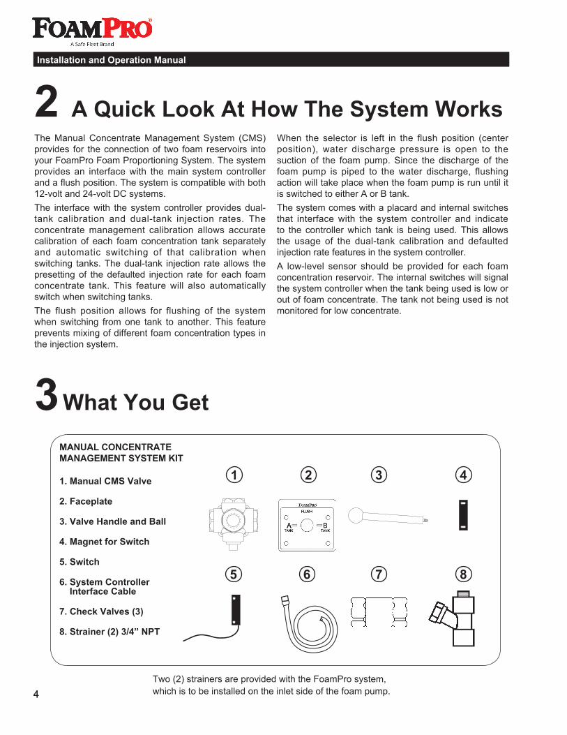
3 What You Get
MANUAL CONCENTRATE MANAGEMENT SYSTEM KIT
1. Manual CMS Valve
2. Faceplate
3. Valve Handle and Ball
4. Magnet for Switch
5. Switch
6. System Controller Interface Cable
7. Check Valves (3)
8. Strainer (2) 3/4” NPT
1 2 3 4
5 6 7 8
Two (2) strainers are provided with the FoamPro system, which is to be installed on the inlet side of the foam pump.

5
Installation and Operation Manual
Manual CMS
4 What You SupplyITEMS NEEDED: 1. Shut-off valves, quarter turn 3/4-inch NPT (two),
(brass). 2. Pipe Tee, to suit water pipe and flush line size. 3. Low pressure, clear suction hoses (3/4-inch
minimum inside diameter). 4. Foam Tanks (two) size to customer’s
specifications.
FOAM TANK TO INTAKE OF FOAM PUMPFittings and hoses from the foam tank to the inlets of the valve will need to be supplied by the installer. Use 1-inch inside diameter hose. Use components that are rated for 23 in. (584 mm) Hg and 50 psi (3 BARS) working pressure. The hose from the valve to the foam pump should be at least 400 psi or greater capacity to withstand the water pressure of the water pumped during flushing. All hoses and fittings must be compatible with the foam concentrates that will be used. NOTE: NFPA requirement: A foam injection check valve is required in the foam pump discharge to prevent backflow of water into the foam concentrate injection system.
SYSTEM WIRINGStandard automotive 14 AWG wire may be used. It is recommended that wiring be bundled with wire ties and protected with loom.NOTE: “A” and “B” are stamped into the bracket for plumbing assembly reference.
5
Installation and Operation Manual
Manual CMS
Optional System Accessories AvailableFoam Tank(s) 8 gallon, polypropylene (P/N 1530-0005)
12 gallon, polypropylene (P/N 1530-0012)
20 gallon, polypropylene (P/N 1530-0022)
Requires additional hardware for compliance with the N.F.P.A.
Strainers
3/4” (P/N 3350-0143) 1” (P/N 3350-0144)
Vertical Mount Low-Level Sensor
(P/N 2510-0028)
Side-Mount Low-Level Sensor
1/2” NPT thread (P/N 2510-0032)
Dual-Tank System Schematic Placard
(P/N 6032-0016)

6
Installation and Operation Manual
6
Installation and Operation Manual
5 Plan AheadBecause of the potential differences in fire apparatus plumbing and foam system configuration, it is not practical to depict exactly how each FoamPro unit will be installed on a particular apparatus. Most of the information contained in the following sections, however, will apply to any situation. It is recommended that you read it thoroughly. It is also recommended
that you spend time planning and designing where and how you intend to install this equipment in the apparatus before beginning the actual installation. The following diagrams provide recommended guidelines for the location of the system components.
6 Plumbing Component InstallationThe system diagram on the following page shows the foam tank to foam pump inlet piping. Always use hose, fittings and pipe compatible with foam agents. All connections must be vacuum tight to ensure proper operation.
The manually-operated valve must be mounted in a position to allow gravity feed from the foam tank, through the valves and to the foam pump.
Manual CMSValve Assembly
Foam Tanks,Fittings and Piping
7
Installation and Operation Manual
Manual CMS
Cal./Inject Valve (provided with foam pump)
7
Installation and Operation Manual
Manual CMS
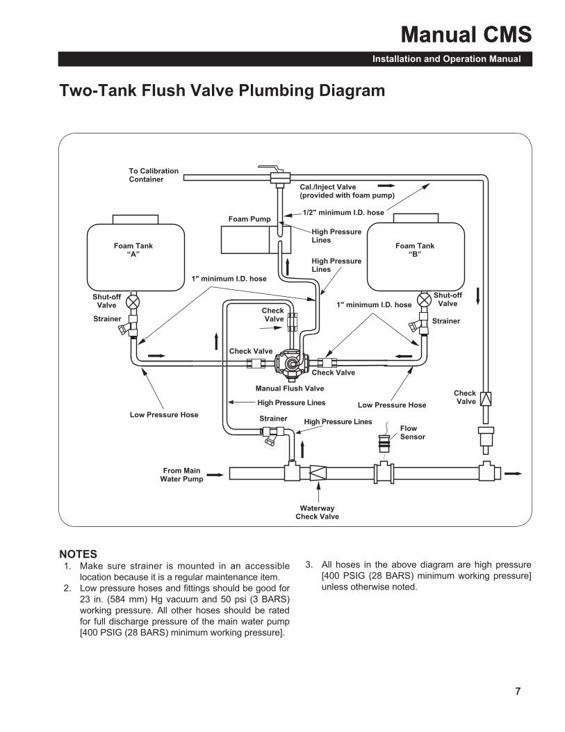
Two-Tank Flush Valve Plumbing Diagram
�
�
�
�
�
�
�
�
�
NOTES 1. Make sure strainer is mounted in an accessible
location because it is a regular maintenance item. 2. Low pressure hoses and fittings should be good for
23 in. (584 mm) Hg vacuum and 50 psi (3 BARS) working pressure. All other hoses should be rated for full discharge pressure of the main water pump [400 PSIG (28 BARS) minimum working pressure].
3. All hoses in the above diagram are high pressure [400 PSIG (28 BARS) minimum working pressure] unless otherwise noted.
To Calibration Container
Foam Tank “A”
Foam Pump
Foam Tank “B”
Shut-off Valve
Shut-off Valve
Strainer
Strainer
Strainer
1" minimum I.D. hose
1" minimum I.D. hose
1/2" minimum I.D. hose
From Main Water Pump
Waterway Check Valve
Low Pressure HoseLow Pressure Hose
Flow Sensor
Check Valve
Check Valve
Check Valve
Check Valve
Manual Flush Valve
High Pressure Lines
High Pressure Lines
High Pressure Lines
High Pressure Lines

8
Installation and Operation Manual
8
Installation and Operation Manual
The FoamPro controller is factory defaulted to the dual-tank option. If the system has been reset or has been placed into the remote start/stop mode, you must change the default setting for proper system operation. The procedure for this new setting starting from the operational mode is as follows: 1. Remove the screws to enter the setup and
diagnostics modes. 2. Enter the setup mode by pressing the internal
button on the left side of the controller once. 3. Enter the configuration mode by pressing the
internal button on the right side of the controller once.
4. The display will flash “CONF” and “RSTART” alternately.
5. Press the UP button once. The display will now flash “CONF” and “DUAL.T” alternately.
6. Press the left internal button once. This will return the controller to the operational mode.
7. Replace the internal button screw covers and o-rings.
Once the system controller is configured to the dual-tank program, the system will be ready for dual-tank configuration and injection rate default settings. Refer to the main system operator’s manual for calibration and default setting procedures.The diagram on the following page shows how to wire the electrical components. The system draws less than 1/4 amps.Use of standard 14 AWG automotive wire that is grease and fuel resistant is recommended. When connecting the wires to the terminals, remove only 1/4-inch of the insulation from the end of the wire. Refer to the electrical connection diagram. Support all wiring, and take care to prevent short circuits.
FOAM TANK LOW-LEVEL SENSORA foam tank low-level sensor must be mounted into the bottom of each foam tank to monitor low concentrate condition. The sensor has 1/8-inch NPT threads. Mount the sensor in the bottom of the foam tank in an upright position. Use suitable sealant to prevent concentrate leakage. There must be room under the tank to route the cable back to the pump/motor base unit.When the bottom of the tank is not accessible, the tank level sensor float switches can be hung from a long nipple attached to the top of the tank. Take care
to ensure the nipple is strong enough to withstand the force of sloshing foam when the vehicle is in motion. Since wire connections must be made inside the nipple, a 3/8-inch NPT nipple with a 3/8 x 1/8-inch NPT reducer at the lower end is the minimum recommended size.NOTE: Install low-level sensor not to interfere with tank discharge.NOTE: Failure to install a low-level sensor will void the FoamPro warranty.Check the low-level sensor with a powered test light. With no foam in the tank, the switch contacts should be closed and the test light should be on. If this is not the case, remove the clip from the end of the low tank sensor. Remove the float, and reinstall 180˚ out of position. Reinstall the clip. Retest the switch to ensure it is working properly.A side-mount, low-level sensor is available to be used if both the top and bottom of the foam tank is not accessible. The side-mount tank level sensor has 1/2-inch NPT threads and must be installed as close to the bottom of the foam tank as possible. After installation, the sensor must be sealed with a suitable sealant to prevent concentrate leakage. Check the side-mount, low-level sensor with a powered test light. With no foam in the tank, the light should be on. If the light does not come on, reposition the switch until the test light is on. Reseal the switch to prevent concentrate leakage after the switch is in the proper position.
7 Electronic Component Installation
Top Mount
Side-Mount Low-Level Sensor (Optional)
Low-Level Sensor
Bottom Mount(Optional)

9
Installation and Operation Manual
Manual CMS
9
Installation and Operation Manual
Manual CMSC
once
ntra
te M
anag
emen
t Sys
tem
Ele
ctric
al H
ooku
p

10
Installation and Operation Manual
10
Installation and Operation Manual
8 Operating InstructionsSelect the desired foam tank by turning the valve lever. The system should always be flushed when switching between tanks. To flush the system: 1. Be sure water is flowing 2. Switch the lever to flush position 3. Turn the FoamPro system on 4. Flush for 8-10 secondsWhen selecting either the A or B foam tank, be certain to move the valve lever until it reaches the internal mechanical stop. Check strainers regularly for excessive contaminants.
NOTE: When servicing the strainers, close the shut-off valves to prevent tank drainage. Make sure the valve is open and the foam pump primed prior to operating the foam system. Priming is made easier by switching the CAL/INJECT valve on the FoamPro to the Calibrate position while the foam pump is operating, allowing air to escape from the foam pump and piping. When foam appears at the CAL/INJECT valve, switch the valve back to the inject position to begin proportioning.
9 TroubleshootingMost Manual Concentrate Management System problems can be traced to faulty wiring. Follow the diagrams carefully and check all connections. Make sure the appropriate, constant DC power is supplied. Excessive electrical interference or momentary low voltage on the power line can cause erratic operation.
Often strainers on a new installation will clog immediately due to excessive debris in the foam tank and hoses from assembly. If strainers are clear and the foam flow rate is low, debris may have become lodged in the valves during assembly. Remove the hose assemblies, and carefully check the valves for debris or obstructions that could block flow. Make sure all strainers are kept clear.
A vertical-mounted (from top or bottom of the tank) foam tank low-level sensor that has the float installed upside down will show a low concentrate reading (LO CON) on the FoamPro display even with a full tank. In this situation, remove the clip, turn float 180º and reinstall the clip. Recheck the sensor.

11
Installation and Operation Manual
Manual CMS
11
Installation and Operation Manual
Manual CMS
11 Installation Illustrations
10 Parts IdentificationMANUAL CONCENTRATE MANAGEMENT SYSTEM KITP/N 3435-0079
Manual CMS ValveP/N 3306-0354
FaceplateP/N 6032-0017
Magnet for Switch
P/N 2530-0094
Switch (3)P/N 2530-0093
CableP/N 2520-0040R
Check Valve (3)P/N 3320-0029SS
Ball for HandleP/N 2802-0009
HandleP/N 2404-0270
Two (2) strainers are provided with the FoamPro system, which is to be installed on the inlet side of the foam pump.
5"
2-1/2"
3/4"
3/4"
2-1/8"
2-7/8"5-3/4"
4-1/4"
ø1-1/4"
ø13/32" (4) Holes
“Flush” PortOutlet Port to Foam Pump Inlet
“B” Tank Port“A” Tank Port
“A” Tank Switch
“B” Tank Switches
Operator’s Panel Placard

12
Installation and Operation ManualInstallation and Operation Manual
12 Limited WarrantyFire Research Corp. (FRC), as supplier of FoamPro, warrants to the original purchaser, each new pump, system or other product of its own manufacture, for a period of two years from the date of shipment from the factory, to be free from defects in material and workmanship under normal use and service. “Normal use and service” means not in excess of recommended maximum speeds, pressures, and temperatures, or handling fluids not compatible with components materials, as noted in applicable FoamPro product catalogs, technical literature, and instructions. This warranty shall not apply to any pump, system or other product which shall have been repaired or altered to adversely affect the performance or reliability of the pump, system or other product.
Neither this warranty nor any implied warranty apply to damage or harm caused by any or all of the following: (1) Freight damage; (2) Freezing damage; (3) Damage caused by parts and/or accessories or components not obtained from or approved by FRC; (4) ANY CONSEQUENTIAL OR INCIDENTAL DAMAGES, OTHER THAN INJURY TO THE PERSON, ARISING FROM THE USE OF ANY PUMP OR OTHER PRODUCT MANUFACTURED BY FRC EXCEPT in states that do not allow the exclusion or limitation of incidental or consequential damages; (5) Damage due to misapplication and/or misuse; (6) Normal wear of moving parts or components affected by moving parts.
The liability of FRC under the foregoing warranty is limited to the repair or replacement at FRC's option without charge for labor or materials of any parts upon return of the entire pump, system or other product or of the particular part to the FRC factory within the warranty period, at the sole expense of the purchaser, which part shall upon examination appear to FRC’s satisfaction to have been defective in material and workmanship. The liability of FRC under any theory of recovery (except any express warranty where the remedy is set forth in the above paragraph) for loss, harm or damage, shall be limited to the lesser of the actual loss, harm or damage or the purchase price of the involved pump, system or other product when sold by FRC to its customer.
FRC expressly warrants its pumps and other products as above stated. THERE ARE NO OTHER EXPRESS WARRANTIES. ANY IMPLIED WARRANTIES, INCLUDING IMPLIED WARRANTY OF MERCHANTABILITY OR OF FITNESS FOR A PARTICULAR PURPOSE, ARE LIMITED IN DURATION TO TWO YEARS FROM THE DATE OF PURCHASE BY THE ORIGINAL PURCHASER EXCEPT in states that do not allow time limitations on implied warranties. THERE IS NO IMPLIED WARRANTY OF FITNESS FOR A PARTICULAR PURPOSE OR MERCHANTABILITY WHEN THIS PRODUCT IS PUT TO RENTAL USE.
No person including any dealer or representative of FoamPro is authorized to make any representation or warranty concerning FRC’s FoamPro products on behalf of FRC, or to assume for FRC the obligations contained in this warranty. FRC reserves the right to make changes in design and other changes and improvements upon its products without imposing any obligations upon itself to install the same, upon its existing products then in process or manufacture.
This warranty gives you specific legal rights, and you may also have other rights which vary from state to state.
IMPORTANT NOTICEIt is imperative to package all FoamPro components properly, before shipment (with Return Goods Authorization attached) back to FRC. The FoamPro contains electronic components that may receive damage from improper shipping procedures! All FoamPro components shipped back to FRC will pass through Quality Control Inspection, and will be photographed after the box is opened. Any shipping damage, such as superficial scratches, nicks, etc., to the unit makes it unusable (even after the internal warranty problem is repaired) and thus must be refinished to “like-new” condition during the warranty process. You are responsible for any physical damage occurring to FoamPro components at your facility and during shipment back to FRC.
Package the FoamPro, complete with all the recommended parts the Customer Service representative requires (i.e., Digital Display control with all premolded wire cables etc.) in its original carton with the Styrofoam and other packaging materials, as it was received at your facility. FRC appreciates your attention in this matter, as we feel it will help us to serve you in a better fashion, while keeping the cost of the FoamPro product competitive. Thank you.
26 Southern Blvd. • Nesconset, NY 11767 USAPhone 800-533-9511 • FAX 816-892-3178www.foampro.com
26 Southern Blvd. • Nesconset, NY 11767 USAPhone 800-645-0074 • FAX 816-892-3178www.fireresearch.com