Manual: CD491 SM HARMANKARDON EN
75
The Harman Kardon Model CD491 _ Manual No. 66A ULTRAWIDEBAND LINEAR PHASE CASSETTE DECK echnical Manual 240 CROSSWAYS PARK WEST. WOODBURY. N.Y. 11797 1112-H15266A1 P-08836 250 PRINTED IN JAPAN. lé6vqd
Transcript of Manual: CD491 SM HARMANKARDON EN
The Harman Kardon
Model CD491 _ Manual No. 66A
ULTRAWIDEBAND LINEAR PHASE CASSETTE DECK
echnical Manual
240 CROSSWAYS PARK WEST. WOODBURY. N.Y. 11797 1112-H15266A1 P-08836 250 PRINTED IN JAPAN.
lé6vqdo

CcD4: SPECIFICATIONS
Track Configuration Cassette Deck
@MECHANICAL SECTION Nominal Limit
Record/Playback Tape Speed Deviation 4.75cm/sec. 0.3% aie
Drift 4.75cem/sec. 0.2% < 0.5% Wow and Flutter
0.033% (CCIR) =0.1%
4-track 2 channel Stereo
0.025% (NAB) = 0.038%
Take Up Torque 55gem + 35~ 70gcem
Back Tension 6gem 4.5 ~ 8gem
F.FWD Torque 120gem 90 ~ 150gcem
REW. Torque 110gem 90 ~ 150gem F.FWD/REW. Time
for C-60 Cassette 72 sec. =85 sec. Motor Direct Drive motor (Capstan)
2 Flat Torque DC motors
(Reel & Assist)
@AMPLIFIRE SECTION Bias Frequency 105kHz + 5kHz
Record/Playback Sensitivity (Input 400Hz) 580mV + 1dB
Signal-to-Noise Ratio at LINE input
(input 1kHz, 100mV) Dolby NR OFF LN 50dB
CrO2 53dB
Metal 52dB
Dolby NRBtoON LN 59dB
CrOz = =61dB=58dB Metal 60dB= 58dB
Dolby NRCtoON LN 69dB
CrO2 71dB = 66dB
Metal 70dB=66dB
Nominal Limit
Signal-to-Noise Ratio at MIC input (Input 1kHz, 1.5mV) Dolby NR B to ON (LN) 50dB= 46dB Dolby NR C to ON (LN) 57dB
Channel Separation 43dB = 35dB Crosstalk. 72dB = 60dB
Record/Playback Distortion
(Input 1kHz) LN 1.3% <1.6%
CrO2 1.0% =3.0%
Metal 1.0% =1.6% MPX Filter Attenuation
at 15kHz 0.3dB <1dB at 19kHz 35dB =30dB
Erase Ratio
(Input 80Hz) LN 70dB = 60dB
Metal 65dB=60dB Input Sensitivity (Input 1kHz)
at MIC input 0.65mV_ —0.2(min) ~ 1.0(max)mV at LINE input = 33mV =. 25(min) ~ 50(max)mV
Input Impedance (Input 1kHz)
at MIC input 1.3kQ. 1(min) ~ 2(max)kQ at LINE input = =23kQ2._—-19(min) ~ 30(max)kQ.
Overload at MIC input (Input 1kHz) 80mV =20mV
DIMENSIONS (WxHxD) 17-7/16"x4-13/16"x13-9/16” (443 x 123 x 345mm)
@WEIGHT 15 Ibs. 14 oz. (7.2 kg)
POWER SUPPLY
U.S.A, & Canada models = AC120V, 60Hz General model AC100/120/220/240v,
50/60Hz POWER CONSUMPTION
U & Canada models 5S5W General modet 60w
PLAYBACK FREQUENCY RESPONSE TEST TAPE: TCC-162C, TCC-262C
+608
RECORD/PLAYBACK FREQUENCY RESPONSE ‘TEST TAPE: XL-1, AC-512, AC-711 DOLBY NR: TYPE B ON 308 308 408
oO °
. ‘ 308 308
an ea zoe 6atle aise suite METAL, Bitte 31.he sisHetkHe sake gor mats
Fig.a Fig.c
RECORD/PLAYBACK FREQUENCY RESPONSE RECORD/PLAYBACK FREQUENCY RESPONSE TEST TAPE: XL-1, AC-512, AC-711 TEST TAPE: XL-1, AC-512, AC-711 DOLBY NR: OFF DOLBY NR: TYPE CON
+30B 4348 +408 +408
oO 0 o
248 308 | sae 308 aHe are ns aate wave ‘20Hz 63H ‘315H2 kHz 16kHz
Fig.b Fig. d
Specifications and components subject to change without notice. Overall performance will be maintained or improved.
This specification is the target of servicing. But, there is a case that the specification is not applicable to the measurement
condition and instrument.

LEAKAGE TEST
Before returning the unit to the user, perform the following safety checks: 1. Inspect all lead dress to make cer-
tain that leads are not pinched or
that hardware is not lodged be-
tween the chassis and other metal Parts in the unit.
2. Be sure that any protective devices such as nonmetallic control knobs, insulating fishpapers, cabinet backs, adjustment and compartment cov- ers or shields, isolation resistor-
capacity networks, mechanical in-
sulators, etc. which were removed for servicing are properly reinstalled.
3. Be sure that no shock hazard exists; check for leakage
current using Simpson Model 229 Leakage Tester,
standard equipment item No. 21641, RCA Model
WTS540A or use alternate method as follows: Plug the AC line cord directly into a 120-volt AC
receptacle (do not use an Isolation Transformer for this test). Using two clip leads, connect a 1500 ohm,
10-watt resistor paralleled by a 0.15mf capacitor, in series with all exposed metal cabinet parts and a
known earth ground, such as a water pipe or conduit,
Use a VTVM or VOM with 1000 ohms per volt, or
higher, sensitivity to measure the AC voltage drop
across the resistor. (See Diagram.) Move the resistor connection to each exposed metal part having a
return path to the chassis (antenna, metal, cabinet,
screw heads, knobs and control shafts, escutcheon,
etc.) and measure the AC voltage drop across the resistor. (This test should be performed with the power switch in both the On and Off positions.)
A reading of 0.35 volt RMS or more is excessive and indicates a potential shock hazard which must be corrected before returning the unit to the owner.
Dolby* HX-Professional Headroom Extension (HX-PRO) System The CD491 is equipped with the Dolby HX-Professional Headroom Extension system (HX-PRO). It operates only during the record mode and does not require the user to “turn it on” or make adjustments. It is compatible with any low noise (standard), chromium dioxide (CrO2), or metal audio cassette tape.
The effect of HX-PRO is that is extends the high fre- quency saturation (overload) level of the tape being recorded. Therefore, many of the high level, high fre- quency music signals that would be compressed or distorted with a conventional cassette deck will be recorded accurately by the CD491.
ae advantages of HX-PRO are: 1. The performance of low noise and chromium dioxide
tapes almost equals that of the more expensive metal tapes. A major improvement is made in high frequency dynamic range.
3. The higher record levels result in an increased signal- to-noise ratio.
4. No decoding is necessary. The improved recording accuracy can be appreciated with any high quality tape player, including a portable or car stereo unit.
5. It can be used with or without Dolby B and C noise reduction circuitry.
N
TO EACH EXPOSED METAL SURFACE OF UNIT UNDER TEST
TO EXPOSED METAL PARTS
Response (dB)
—40 1000 20005000 10000-20000 50000
SIMPSON MODEL 229 ETC, FOR LEAKAGE TEST
TO AC GROUND SUCH AS WATER OR GAS PIPE,
HIGH BX CABLE, CONDUIT, ETC. VOLTAGE OR +LEAD
LEAD
OAC SCALE O
0.15 MF
TEST PROBE
CONNECT TO KNOWN EARTH GROUND
Hx-PAOs Day CON! J
HXPROON, Dowy COFF
WXPRO & Dolby C OFF
Frequency (Hz) Frequency Response |
“Noise reduction and headroom extension manufac- { tured under license from Dolby Laboratories Licensing Corporation. HX Professional originated by Bang and Olufsen. “Dolby” and the double-D symbol are trade- marks of Dolby Laboratories Licensing Corporation.

DISASSEMBLY PROCEDURES (REFER TO PAGES 17, 18, 19 AND 30)
w
2
CABINET TOP REMOVAL. Remove 6 screws @ and remove the cabinet top.
FRONT PANEL ASSEMBLY (103) REMOVAL 1, Remove the cabinet top. (Refer to step [1] .) 2. Pull off Master Fader, Output Level, Mic. Level
and Rec. Level knobs (105 and 152). 3. Remove 6 screws © and remove the front panel
assembly (103).
LOGIC CONTROL P.C.BOARD(PCB-2) REMOVAL 1. Remove the cabinet top. (Refer to step [1] .) 2. Disconnect J801, J802, J803, J808 and J809
from P801, P802, P803, P808 and P809 on the logic control P.C. board (PCB-2).
3. Open the lid of connectors (P804, P805, P806 and P807) on the logic control P.C. board (PCB-2) and disconnect the lead wires.
4. Unsolder the lead wires connected to the logic control P.C. board (PCB-2).
5. Remove 4 screws @ and remove the logic control P.C. board (PCB-2) with heat sink (301),
PUSH SWITCHES P.C.BOARD(PCB-4) REMOVAL 1, Remove the cabinet top. (Refer to step [) .) 2. Open the lid of connectors P451, J803, P804
and P401) on the main, logic control and VR P.C. boards (PCB-1, PCB-2 and PCB-3) and disconnect the lead wires.
3. Remove 3 screws ®and remove the push switches P.C. board (PCB-4) with rec. cal P.C. board (PCB-9). If necessary, unsolder the lead wires.
MAIN P.C. BOARD (PCB-1) REMOVAL 1, Remove the front panel assembly, logic control
P.C. board (PCB-2) and push switches P.C. board (PCB-4). (Refer to steps [2] through I .) Disconnect J501 and J503 from P501 and P503 ‘on the main P.C, board (PCB-1).
3. Open the lid of connectors (P201, P202, P251, P301, P502, P551 and P601) on the main P.C. board (PCB-1) and disconnect the lead wires.
4, Unsolder lead wires connected to the main P.C, board (PCB-1).
5. Remove 2 screws @and remove the tape monitor switch (SW406).
6. Remove 8 screws @ and remove the main P.C. board (PCB-1).
La
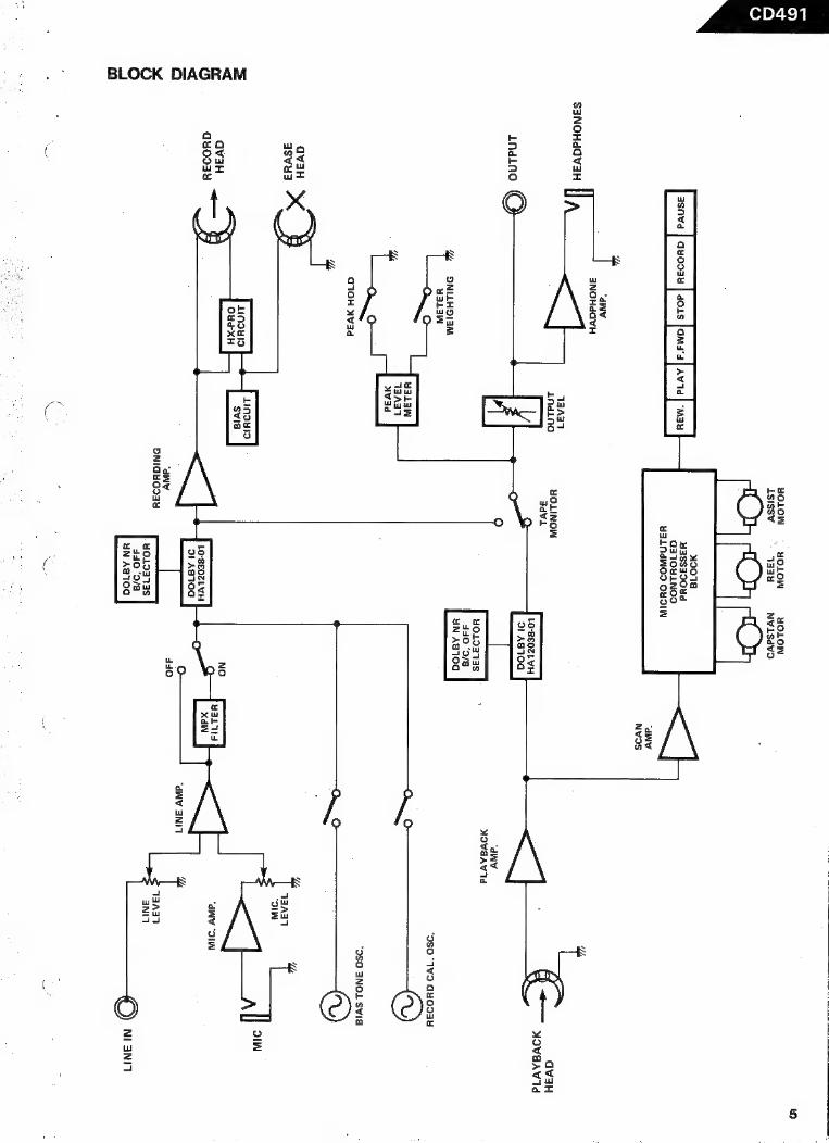
cout DESCRIPTION @ MPX/DOLBY NR CIRCUIT
The MPX filter circuit is turned on and off by the MPX filter switch. When it is off, the signals bypass the circuit. The dolby circuit is turned on and off by the dolby NR switch, and selected B and C types by the dolby NR type selector. When the circuit is on and type selector is B position, B-type dolby equalization is applied so that the signal is compress- ed during recording and expanded during playback.
MUTING . PLAYBACK MODE When the play button is pressed, the muting signal for the playback mode (which cuts the recording signal) is output from () pin of the 4 bit micro computer 1C851 and applied to Q701 (left channel) and Q702 (right channel). This turns on Q701 and Q702 to mute the recording signal.
2.
3.
VR P.C, BOARD (PCB-3) REMOVAL 1. Remove the front panel assembly. (Refer to step
2.) 2, Remove 6 screws @ and remove the cabinet
bottom assembly (102). 3. Remove 4 hexagon nuts @ mounting the VR
P.C. board (PCB-3) and remove it.
CASSETTE TAPE RECORDER MECHANICAL ASSEMBLY (113) REMOVAL 1, Remove the front panel assembly and logic
control P.C. board (PCB-2). (Refer to steps (2) and (3) .)
2. Remove 4 screws @ and remove the cassette tape recorder mechanical assembly (113) with plate assembly (104) backward.
PLATE ASSEMBLY (104) REMOVAL 1, Remove the cassette tape recorder mechanical
assembly. (Refer to step [2 .) 2. Remove 2 screws @ and remove the plate
assembly (104).
DIRECT DRIVE MOTOR (506) REMOVAL 1, Remove the plate assembly. (Refer to step 2. Remove 2 hexagon nuts @
direct drive moto?. lead wires.
) and remove the
If necessary, unsolder the
PAD ASSEMBLY (505) REMOVAL 1, Remove the plate assembly. (Refer to step 5} .) 2, Remove 2 screws @ and remove PAD assembly.
If necessary, unsolder the lead wires.
IDLER MOTOR ASSEMBLY (503) REMOVAL 1, Remove the direct drive motor. (Refer to step
) 2, Remove 2 lock washers ({) and remove supply
and take-up reel spindle assembly (508 and 509). At this time, remove the belt (511) and spring (507).
3. Remove 3 screws @® and remove the idler motor assembly.
HEAD BASE ASSEMBLY (502) REMOVAL 1, Remove the direct drive motor. (Refer to step
) 2. Remove 2 E-stop rings ® and remove supply and
take-up pinch roller assembly (516 and 513). 3. Remove the lamp holder assembly (519) and
lamp holder mounting bracket. 4, Remove 2 E-stop ring @ and remove head base
assembly with record/playback and erase heads.
RECORDING MODE When the record button is pressed, the muting signal for the record mode (which cuts the playback signal) is output from @ pin of 1C851 and applied to 091 (left channel) and Q92 (right channel). This turns on Q91 and 092 to mute the playback signal.
LINE MUTE (POWER SWITCH ON/OFF) When the power is turned on, 051 is turned on for a few seconds. At the same time Q93 and Q94 go on. @ pin of the 4 bit micro computer 1C851 becomes high level. The computer is reset. At the same time Q91 (left channel) and Q92 (right channel) are turned on. Thus, no shock noise is output to the OUTPUT terminals.
¢ i:
HOLON
=
HOLOW
HOLOW
Asissv
7334
NVisdvo
waSS300Ud g3081LNOO YaLNdWOD ONIN
pees
on
eo
“awy
3NOHdOVH
SaNOHdQV3H
1 indian
wouwon
avan
ieeeoe
Tv
OVEAVITd
ndino
o1aAs10a
“dV
wowE,
40193748
‘
Oe
440
‘9/8
SNILHOISM
uN.Ag
ION
43L3W
“ISO “Iv9 GHO9ay
jee
"9SO 3NOL SVIa-
10H
AW3d
€)
.
av3H ,
asvaa
IW
Ss
LInoUID
a539)
tf Oud-XH
a
Gv3aH
e344
“awv
oO
ayooay
ToaEecl
GH
Xd
‘dW
“SIN
<z : ‘91A8700
a “dW 3NIT
“dV
x
ONIGHOOaY
VaAa
¥O1L9373S
ann
440
‘0/8
a
YN AgTOG
Nrann
oO
(
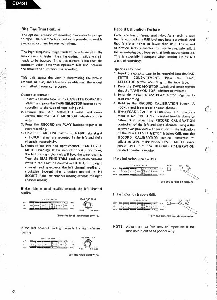
Bias Fine Trim Feature
The optimal amount of recording bias varies from tape to tape. The bias fine trim feature is provided to enable precise adjustment for such variations.
‘The high frequency range tends to be attenuated if the
bias current is higher than the optimum value while it
tends to be boosted if the bias current is less than the optimum value. Less than optimum bias also increases the amount of distortion in a recording.
This unit assists the user in determining the precise amount of bias, and therefore in obtaining the widest and flattest frequency response.
Operate as follows: 1. Insert a cassette tape in the CASSETTE COMPART-
MENT and press the TAPE SELECTOR button corre-
sponding to the type of tape being used. 2. Depress the TAPE MONITOR switch and make
certain that the TAPE MONITOR indicator illumi-
nates.
3. Press the RECORD and PLAY buttons together to
start recording.
4. Hold the BIAS TONE button in. A 400Hz signal and
a 12.5kHz signal are recorded in the left and right channels, respectively.
. Compare the left and right channel PEAK LEVEL
METER readings. If the amount of bias is optimum,
the left and right channels will have the same reading. Turn the BIAS FINE TRIM knob counterclockwise
(toward the direction marked as HI CUT) if the right
channel reading exceeds the left channel reading or
clockwise (toward the direction marked as Hi
BOOST) if the left channel reading exceeds the right
channel reading.
a
If the right channel reading exceeds the left channel reading:
BIAS FINE TRIM
Turn the knob counterclockwise.
|f the left channel reading exceeds the right channel
reading:
BIAS FINE TRIM
MOT peut 4ni boost
Turn the knob clockwise.
Record Calibration Feature
Each tape has different sensitivity. As a result, a tape
that is recorded at a OdB level may have a playback level
that is either higher or lower than OdB. The record
calibration feature enables the user to precisely adjust
the record/playback level so that both modes correlate,
This is especially important when making Dolby NR
encoded recordings.
Operate as follows: 1, Insert the. cassette tape to be recorded into the CAS-
SETTE COMPARTMENT. Press the TAPE
SELECTOR button according to the tape type.
2. Press the TAPE MONITOR switch and make certain
that the TAPE MONITOR indicator illuminates, 3. Press the RECORD and PLAY button together to
start recording.
4. Hold in the RECORD CALIBRATION button. A
400Hz signal is recorded on each channel.
. If the PEAK LEVEL METERS show OaB, no adjust-
ment is required. If the indicated level is above or
below OdB, adjust the RECORD CALIBRATION
control{s) of the left and right channels using a the screwdriver provided with your unit. If the indication
of the PEAK LEVEL METER is below OdB, turn the
RECORD CALIBRATION control clockwise to adjust to OdB. If the PEAK LEVEL METER reads above OdB, turn the RECORD CALIBRATION
control counterclockwise.
a
If the indication is below OdB.
ene (even METER cee cal left right SSCS) ur ae
i oo i mat
Turn the controls clockwise,
\f the indication is above OdB.
Peak LeveL METER 06 cal left right ©
‘Turn the controls counterclockwise.
NOTE: Adjustment to OdB may be impossible if the
tape used is old or of poor quality.
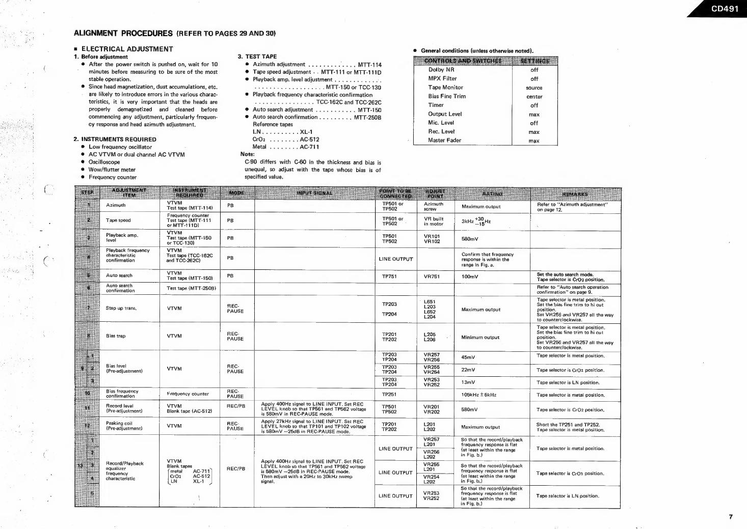
ALIGNMENT PROCEDURES (REFER TO PAGES 29 AND 30)
= ELECTRICAL ADJUSTMENT 1. Before adjustment 3. TEST TAPE
( ©@ After the power switch is pushed on, wait for 10 © Azimuth adjustment ............. MTT-114
minutes before measuring to be sure of the most © Tape speed adjustment . . MTT-111 or MTT-111D Dolby NR off stable operation. © Playback amp. level adjustment ............. MPX Filter off
®@ Since head magnetization, dust accumulations, etc. ee eee eee eee MTT-150 or TCC-130 Tape Monitor source are likely to introduce errors in the various charac- @ Playback frequency characteristic confirmation Bias Fine Trim center
teristics, it is very important that the heads are TCC-162C and TCC-262C Timer off
Properly demagnetized and cleaned before © Auto search adjustment . . MTT-150 Output Level
commencing any adjustment, particularly frequen- © Auto search confirmation......... MTT-250B Oren = ‘ cy response and head azimuth adjustment. Reference tapes Mic. Level off % LN.... oe XL Rec. Level max 5 2. INSTRUMENTS REQUIRED CrO2 «+ AC512 Master Fader max
© Low frequency oscillator Metal ........ AC-711 @ AC VTVM or dual channel AC VTVM Note: ®@ Oscilloscope C-90 differs with C-60 in the thickness and bias is © Wow/flutter meter unequal, so adjust with the tape whose bias is of © Frequency counter specified value.
( Mi EES
VTVM TP501 or | Azimuth ; Refer to “Azimuth adjustment” eds Test tape (MTT-114)_| PB TP502 screw Maximum sutpat on page 12. Frequency counter F i P8501 or VR built +30 7 Tape speed Test tape (MTT-111 PB ee VE allt kHz *30 Hz
" viva Playback amp. 7P501 vrio1 Test tape(MTT-150 | PB 580mV level ert tape (mt TP502 VR102
: Peacace frequency, YINM Confirm that frequency hi : C Poeteaet td See Bee CG eRe. || ag LINE OUTPUT response is within the C range in Fig. a. i vive Set the auto search mode. Auto search Test tape (MTT-150) | PE TP761 A761 tomy Tape selector is CrO2 position.
‘Auto search ; Refer to “Auto search operation ot seh. Test tape (MTT-2508) confirmation” on page 9. naar Tape selector is metal position.
eee: TP203 res) Set the bias fine trim to hi cut Step up trans. vtvm proce te Maximum output position. TP204 rd Set VR256 and VR257 all the way
to counterclockwise. Tape selector is metal postion. ; et the bias fine trim to hi cut Bias trap vTvM Gee aba tae Minimum output position. Set VR256 and VR267 all the way to counterclockwise.
7P203 VR287 Tape selector is metal position. TP204 VR256 omy. < j ee
Bias level REC. 76203 VR255 ; Teecaesneail vive aes Teas yaaa 22mV Tape selector is CrO2 position.
pice veaes 13mVv Tape selector is LN position.
Biles Trequency Frequency counter Bae 1P251 105kHz + SkHz Tape selector is metal position. Apply 400Hz signal to LINE INPUT. Set REC Record level vtvm REC/PB TP501 vR201 P an, ; LEVEL knob so that TPS61 and TPS62 voltage s80mV Tape selector is CrO2 position. (Pre-adjustment) Blank tape (AC-512) EME E knob so thet Teee | ond TP502 vR202
Par Apply 27kHz signal to LINE INPUT. Set REC Peaking coil REC- 7P201 L201 ‘ Short the TP251 and TP26 9 v 5s (Pre-adjustment) Tea PAUSE HOSOI eee ee eae ag voltae 7P202 L202 Maximum output Tape selector is metal position.
VA257 So that the record/playback L201 frequency response is flat , a LINE OUTPUT |—jaoee lat least within whe faivoe Tape selector is metal position. ( Ne in Fig. b.)
vtvM Apply 400H2 signal to LINE INPUT. Set REC pecata/Ptaybork Blank tapes RECRE LEVEL knob so that TP661 and TPS62 voltage zoe So that the record/playback
metal AC-711 is 680mV —25dB in REC-PAUSE mode. LINE OUTPUT frequency response #3 Tr T lector i ition. frequency CrO2 AC-512 Then adjust with a 20Hz to 30kHz sweep VR254 {at least within the range ae Solero. C02 Pesren characteristic rote cate seals L202 in Fig. b.) yess So that the record/playback R253 frequency response is flat i ts \ LINE OUTPUT | Vroes (reer Cathie ahs cos Tape selector is LN position.
in Fig. b.)

ALIGNMENT PROCEDURES (REFER TO PAGES 29 AND 30)
= ELECTRICAL ADJUSTMENT 1. Before adjustment
@ After the power switch is pushed on, wait for 10
minutes before measuring to be sure of the most stable operation.
@ Since head magnetization, dust accumulations, etc.
are likely to introduce errors in the various charac-
teristics, it is very important that the heads are
properly demagnetized and cleaned before
commencing any adjustment, particularly frequen-
cy response and head azimuth adjustment.
2. INSTRUMENTS REQUIRED
@ Low frequency oscillator
AC VTVM or dual channel AC VTVM
Oscilloscope
3. TEST TAPE © Azimuth adjustment .........025- MTT-114 © Tape speed adjustment . . MTT-111 or MTT-111D © Playback amp, level adjustment ........ 0000.
erie aicntenatceart yack hear MTT-150 or TCC-130 © Playback frequency characteristic confirmation
ehh PUA deg ban Me TCC-162C and TCC-262C © Auto search adjustment ........... MTT-150.
© Auto search confirmation......... MTT-250B Reference tapes LN... XL-1
CrO2 AC-512
Metal . AC-711 Note:
C-90 differs with C-60 in the thickness and bias is
unequal, so adjust with the tape whose bias is of
. e © Wow/flutter meter @ Frequency counter specified value.
; VIVM ? “TP5O1 or Aaimatty Test tape (MTT-114) | PB TP502
Frequency counter Tape speed Test tape (MTT-111 PB aeeoL or
or MTT-111D) viv
Playboy am: Test tape (MTT-150 PB pee or TCC-130)
Playback frequeney viv ic Test tape (TCC-162C “i and TCC-262C) Fe CINE‘OUTRUT:
viv Auto search Yor oeimTt-i6o) | PB 1P751 ‘Auto search ile eae Test tape (MTT-250B)
TP203 REC. Step up trans. viv ie aay
F REC- 7P201 Bias trap vtvM re Teoh
7P203 TP204
Bias level REC. TP203 (Pre-adjustment) NIV PAUSE TP204
TP203 TP204
Bias frequency REC. Bi frequen Frequency counter Bas TP251 atcag ioe 7) RECIPE ‘Apply 400Hz signal to LINE INPUT, Set REC TpeOi (Pre-adjustment) Blank tape (AC-512) OE Ta RUC eee TP5O2
ae : Apply 27kHz signal to LINE INPUT. Set REC Venicing coll vtvM Lara LEVEL knob so that TP101 and TP102 voltage eae
i is S80mV —26dB in REC-PAUSE mode.
LINE OUTPUT
viv Apply 400Hz signal to LINE INPUT. Set REC Berea ence Blank tapes RECIPE LEVEL knob so that TP561 and TP562 voltage ecrusiizs metal AC-711 is 580mV ~26dB in REC-PAUSE mode. LINE OUTPUT paver CrO2 AC-512 Then adjust with a 20Hz to 30kHz sweep characteristic ord oa vacate
‘ LINE OUTPUT
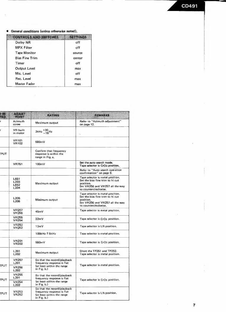
© General conditions (unless otherwise noted).
MPX Filter
Tape Monitor
Bias Fine Trim
Timer
Output Level
Mic. Level
Rec. Level
Master Fader
off
off
source center off
max off
max max
Refer to “Azimuth adjustment” 7 ‘Azimuth ; Balen Maximum output isietorh
r VR built +30 in motor kHz “age
vator Wilt 580mV
Confirm that frequency PUT response is within the
range in Fig. a.
‘oom Set the auto search mode, MBEY ‘loom: Tape selector is CrO2 position.
Refer to “Auto search operation confirmation” on page 9.
L661 Tape selector is metal position. he Set the bias fine trim to hi cut ho Maximum output position. on Set VR256 and VR257 all the way
to counterclockwise. Tape selector is metal position,
ions Set the bias fine trim to hi cut toe Minimum output position.
Set VR256 and VR257 all the way to counterclockwise.
VR257 Tape selector is metal position. VR256 spy 3
vate 22mv Tape selector is CrO2 position.
ynees 13mV Tape selector is LN position.
105kHz + SkHz Tape selector is metal position.
year 580mV Tape selector is CrO2 position.
L201 ; Short the TP251 and TP252. 202 Maximum'output Tape selector is metal position.
VR257 So that the record/playback L201 frequency response is flat , - PUT | aoeg (et leost within tha ranae Tape selector is metal position. vgs in Fig. b.)
Atte So that the record/playback frequency response is flat , 4
[rPUT VR254 (at least within the range Tape selector is CrO2 position.
202 in Fig. b.) So that the record/playback
R253 frequency response is flat , TPUT | R252 {at least within the range “Tape selector IsLN posizion.
in Fig. b.)
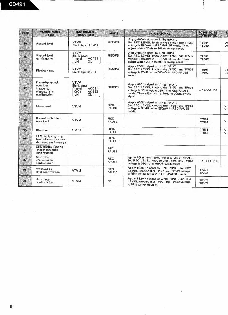
Apply 400Hz signal to LINE INPUT. coed tl vivm REC/PB Set REC LEVEL knob so that TP561 and TP562 | TP501 VF ene Blank tape (AC-512) voltage is S80mV in REC-PAUSE mode. Then TP502 VF
adjust with a 20Hz to 30kHz sweep signal. vivm Apply 400Hz signal to LINE INPUT.
Record level Blank tapes REC/PB Set REC LEVEL knob so that TP561 and TP562 | TP501 confirmation metal AC-711 voltage is S80mV in REC-PAUSE mode. Then TP502 LN xLA adjust with a 20Hz to 30kHz sweep signal,
Apply 250Hz signal to LINE INPUT. bata VTVM REC/PB Set REC LEVEL knob so that TP561 and TP562 | TP5O1 u jeyback: trap. Blank tape (XL-1) voltage is 25dB below 580mV in REC-PAUSE TP502 u mode.
een pleybant pele Apply 400Hz signal to LINE INPUT. uciene, ba fal AC TIT REC/PB Set REC LEVEL knob so that TP561 and TP562 Heo te Con eesie voltage is 25dB below 580mV in REC-PAUSE LINE OUTPUT
Chatmcteristie A mode, Then adjust with a 20Hz to 30kHz sweep confirmation tn xL4 Ganar
Apply 400Hz signal to LINE INPUT. REC- Set REC LEVEL knob so that TP561 and TP562 VF Meter: level ve PAUSE voltage is 0.5dB below 580mV in REC-PAUSE VF mode.
Record calibration REC- TPS61 tone level NIYM PAUSE TP562 bk
7 REC- TP561 VR Bias tone viv RAUSE Aly ve LED display lighting 3 level of record calibra- ine tion tone confirmation LED display lighting 7 level of bias tone Broa confirmation MPX filte Bee Apply 15kHz and 19kHz signal to LINE INPUT. characteristic PAUSE Set REC LEVEL knob so that TP561 and TP562 | LINE OUTPUT confirmation voltage is 580mV in REC-PAUSE mode.
P - Apply 19.9kHz signal to LINE INPUT. Set REC eoruaten a VTVM A uee LEVEL knob so that TP561 and TP562 voltage oes ever contra is 25dB below S80mV in REC-PAUSE mode. Apply 19.9kHz signal to LINE INPUT. Set REC Boost level 7P501 Conte vtvm PB LEVEL knob so that TP501 and TP502 voltage TPS02 is 25dB below 580mv.
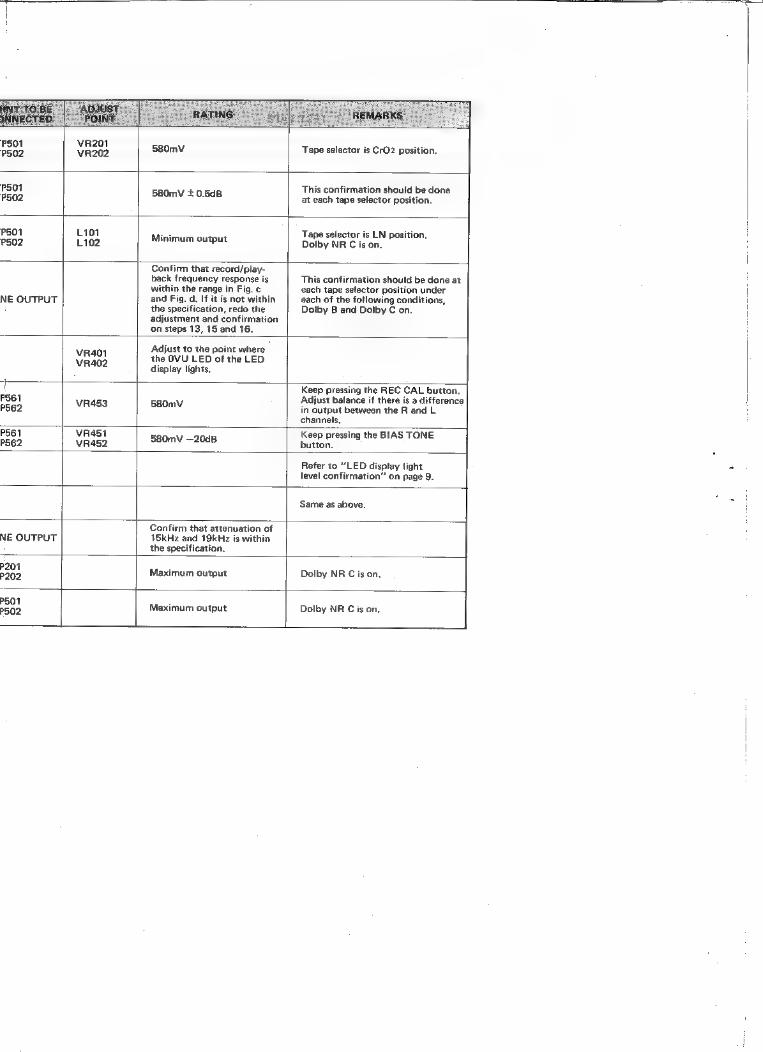
foo. veeor 580mV Tape selector is CrO2 position.
P5O1 2 This confirmation should be done P502 PaO = 0.08. at each tape selector position.
P01 L101 : Tape selector is LN position. P502 L102 Minimum output Dolby NR Cis on.
: Confirm that record/play- back frequency response is This confirmation should be done at within the range in Fig. c each tape selector position under
NE OUTPUT and Fig. d. If itis not within | each of the following conditions, the specification, redo the Dolby B and Dolby C on. adjustment and confirmation on steps 13, 15 and 16.
Adjust to the point where Masedd the OVU LED of the LED
display lights. t Keep pressing the REC CAL button. PS61 Adjust balance if there is a difference P562 YEAS Bala: in output between the R and L
channels, P561 VRa51 7 Keep pressing the BIAS TONE P562 vR452 Beomy:—20de: button.
Refer to “LED display light level confirmation” on page 9.
Same as above.
Confirm that attenuation of NE OUTPUT 18kHz and 19kHz is within : the specification.
_ Maximum output Dolby NR Cis on.
P50 P502 Maximum output Dolby NR Cis on,
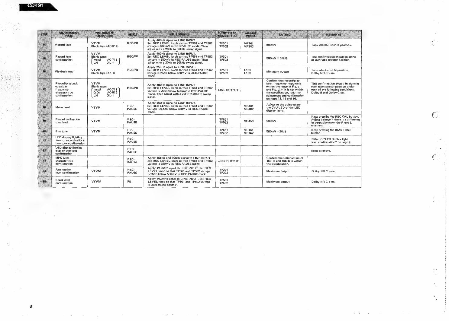
PF ig Set viv REC/PB REC LEVEL TP501 va201 7
Record evel Blank tape (AC-512) voltage is 580mV in REC-PAUSE mode. Then ‘TP5O2 R202 BeOmy) (Tape selectors C192 Rosition: adjust with a 20Hz to 30kHz sweep signal.
VIVM ‘Apply 400Hz signal to LINE INPUT. Record level Blank tapes REC/PB Set REC LEVEL knob so that TP561 and TPS62 | TPSot eaom¥O.bde This confirmation should be done confirmation metal AC-711 voltage is S80mV in REC-PAUSE mode. Then 7P502 #08 at each tape selector position.
LN xt adjust with a 20Hz to 30kHz sweep signal. fase Apply 250Hz signal to LINE INPUT. +
vTvM Set REC LEVEL knob so that TP561 and TP562 | TPSO1 L101 , ape selector is LN position. Playback: tap Blank tape (XL-1) voltage is 25dB below 580mV in REC-PAUSE TP502 L102 Minimum output Dolby NR Cis on.
; mode. 4 ; Confirm that record/play- ; Record/playback viv , back frequency response is This confirmation should be done at i equalizer Blank tapes REGIS: Pcie suc keidertie erent ee ee within the range in Fi each tape selector position under i frequency metal AC-711 ee ae chy hun Rabin HEC eAtiSe LINE OUTPUT and Fig. d. If it isnot within | each of the following conditions,
characteristic Croz— AC-512 rrdde Than 'ediuct tinthr # 20be tw SURF > ores : the specification, redo the Dolby B and Dolby C on. confirmation UN x4 aon : P adjustment and confirmation
ise on steps 13, 15 and 16. ‘Apply 400Hz signal to LINE INPUT. F F
paren eau REC- Set REC LEVEL knob so that TP561 and TP562 vR401 Ma Gieberaetee xg PAUSE voltage is 0.508 below S80mV in REC-PAUSE vR402 Phat voli isplay lights. |
i iKeep pressing the REC CAL button. Record calibration REC- TPS61 Adjust balance if there is a difference tone level MIM PAUSE ‘TP562 yates, peony’ in output between the R and L
channels.
am ven Biles Te | SES [sow an Kern ASTON] LED display lighting i is EEO cleplay lighting & REC- Refer to “LED display light tion tone confirmation PAUSE level confirmation” on page 9. LED display lighting REC- level of bias tone Puce Same as above. confirmation MPX filter Eee ‘Apply 18kHz and 19kHz signal to LINE INPUT. Confirm that attenuation of characteristic PAUSE Set REC LEVEL knob so that TP561 and TP562 LINE OUTPUT 15kHz and 19kHz is within
F confirmation voltage is S80mV in REC-PAUSE mode. the specification. : ‘Apply 19.9kHz signal to LINE INPUT, Set REC
AttSRUEONL, vivm BEC. LEVEL knob so that TPS61 and TP562 voltage TP201 Maximum output Dolby NR Cis on. level confirmation PAUSE 7P202 ne consimatiot is 25dB below 580mV in REC-PAUSE mode. Apply 19.9kHz signal to LINE INPUT. Set REC
Boost level VTVM PB LEVEL knob so that TP501 and TP502 voltage areot Maximum output Dolby NR C is on. confirmation dee teat aicah TP502 | :
{
} { i

cS
=
AUTO-SEARCH OPERATION CONFIRMATION
Conditions
Test tape MTT-250B
Tape Selector CrO2z
Dolby NR off
- Wind the test tape to its end and reset the counter to “0000”.
. Press the REW key to rewind the tape until the
counter indicates around “9500”.
. Check for the following operation by pressing the:
F.FWD key and the PLAY key simultaneously.
Stop Auto-search (2 ~ 5 sec.) fee F.FWD key and ] ee indicator lights al PLAY key simultaneously. | F.FWD indicator flashes.
~>Rewind (about 0.5 sec.) —~Playback
. Repeat the same check as in step 3 a few times by pressing the F.FWD key and the PLAY key simulta-
neously.
5. With the test tape rewound fully, reset the counter to
“0000”.
6. Wind the tape on quickly until the counter indicates
around “0050” by pressing the F.FWD key.
7. Check for the following operation by pressing the
REW. key and the PLAY key simultaneously.
Stop Auto-search (2 ~ 5 sec.) Press REW.key and PLAY ] [PLAY indicator lights and key simultaneously. REW. indicator flashes.
—>Rewind (about 0.5 sec.) —~ Playback
8. Repeat the same check as in step 7 a few times by
pressing the REW. key and the PLAY key simultane- ously.
LED DISPLAY LIGHTING LEVEL CONFIRMATION
Conditions (unless otherwise noted) Output Level ..... ++ Center Mic. Level ...... . . Off Bias Fine Trim .. . . - Center DolbyNR...... . Off MPX Filter ..... z . Off
Tape Monitor... .. seeee . Monitor Connect a 10k load resistors to LINE OUTPUT.
. Dolby NR light level confirmation
Play back the test tape (MTT-150) and confirm that the LED display lights to OVU with the tape selector
at both the LN position and the CrO2 position. If the
display does not operate as described above, make
a readjustment by repeating steps 3 and 18 of
Electrical Adjustment.
REC. CAL. TONE and BIAS TONE light level con-
firmation 1) With the tape monitor switch set to source and the
tape selector at the CrO2 position, set the unit in
the REC-PAUSE state. Then confirm that the LED
display lights to OVU when the REC CAL button
is pressed.
If the display does not operate as described above, make a readjustment by repeating step 19
of Electrical Adjustment.
© Test tape MTT-150 @ Reference tapes
tN XL-1 CrO2 AC-512
Metal AC-711
2) Check to ensure that the LED display lights to
OVU when the BIAS TONE button is pressed.
If the display does not operate as described above, make a readjustment by repeating step 20
of Electrical Adjustment.
3) With the tape selector at the LN and then the Metal position, check to ensure that the LED display reading does not change when the buttons are pressed as in steps 1) and 2).
10
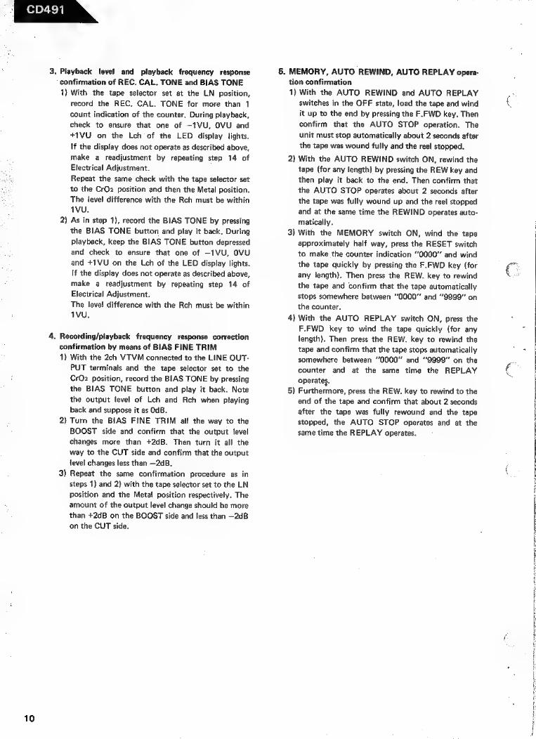
3. Playback level and playback frequency response
confirmation of REC. CAL. TONE and BIAS TONE
1) With the tape selector set at the LN position, record the REC. CAL. TONE for more than 1
count indication of the counter. During playback, check to ensure that one of —1VU, OVU and
+1VU on the Leh of the LED display lights.
If the display does not operate as described above,
make a readjustment by repeating step 14 of
Electrical Adjustment.
Repeat the same check with the tape selector set
to the CrO2 position and then the Metal position.
The level difference with the Rch must be within 1VU.
2) As in step 1), record the BIAS TONE by pressing
the BIAS TONE button and play it back. During
playback, keep the BIAS TONE button depressed and check to ensure that one of —1VU, OVU
and +1VU on the Lch of the LED display lights.
If the display does not operate as described above,
make a readjustment by repeating step 14 of
Electrical Adjustment. The level difference with the Rch must be within
vu.
4. Recording/playback frequency response correction
confirmation by means of BIAS FINE TRIM 1) With the 2ch VTVM connected to the LINE OUT-
PUT terminals and the tape selector set to the CrO2 position, record the BIAS TONE by pressing the BIAS TONE button and play it back. Note
the output level of Lch and Rch when playing
back and suppose it as OdB.
2) Turn the BIAS FINE TRIM all the way to the
BOOST side and confirm that the output level
changes more than +2dB. Then turn it all the way to the CUT side and confirm that the output
Jevel changes less than —2dB.
3) Repeat the same confirmation procedure as in steps 1) and 2) with the tape selector set to the LN position and the Metal position respectively. The amount of the output level change should be more
than +2dB on the BOOST side and less than —-2dB
‘on the CUT side.
5. MEMORY, AUTO REWIND, AUTO REPLAY opera- tion confirmation 1) With the AUTO REWIND and AUTO REPLAY
switches in the OFF state, load the tape and wind it up to the end by pressing the F.FWD key. Then
confirm that the AUTO STOP operation. The
unit must stop automatically about 2 seconds after
the tape was wound fully and the reel stopped.
2) With the AUTO REWIND switch ON, rewind the
tape (for any length) by pressing the REW key and
then play it back to the end. Then confirm that the AUTO STOP operates about 2 seconds after
the tape was fully wound up and the reel stopped
and at the same time the REWIND operates auto- matically.
3) With the MEMORY switch ON, wind the tape approximately half way, press the RESET switch
to make the counter indication “0000” and wind
the tape quickly by pressing the F.FWD key (for
any length). Then press the REW. key to rewind
the tape and confirm that the tape automatically
stops somewhere between “0000” and “9999” on the counter.
4) With the AUTO REPLAY switch ON, press the
F.FWD key to wind the tape quickly (for any length). Then press the REW. key to rewind the
tape and confirm that the tape stops automatically
somewhere between “0000” and “9999” on the counter and at the same time the REPLAY operates.
5) Furthermore, press the REW. key to rewind to the
end of the tape and confirm that about 2 seconds after the tape was fully rewound and the tape
stopped, the AUTO STOP operates and at the
same time the REPLAY operates.
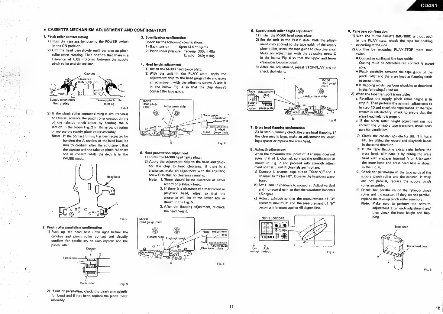
= CASSETTE MECHANISM ADJUSTMENT AND CONFIRMATION
1. Pinch roller contact timing
A 1) Run the capstans by placing the POWER switch in the ON position.
2) Lift the head base slowly until the take-up pinch
roller starts rotating. Then confirm that there is a clearance of 0.05~ 0.5mm between the supply
pinch roller and the capstan.
Capstan
‘Clearance 0.05 ~ 0.5 mm
O) p—! — (\ © =
5 CLIO = Supply pinch roller ‘Take-up pinch roller
Not rotating Rotating
Fig. 1
( ; 3) If the pinch roller contact timing is simultaneous or reverse, advance the pinch roller contact timing
of the take-up pinch roller by bending the A section in the below Fig. 2 in the arrow direction
¥ or replace the supply pinch roller assembly. : Note: If the contact timing has been adjusted by
bending the A section of the head base, be
Pak sure to confirm after the adjustment that
the capstan and the take-up pinch roller are € not in contact while the deck is in the
: PAUSE mode.
Head base
Fig, 2
inch roller parallelism confirmation
1) Push up the head base until right before the
capstan and pinch roller contact and visually confirm for parallelism of each capstan and the
pinch roller. Capstan
Parallelism
Pinch roller Fig. 3
2) If out of parallelism, check the pinch arm spindle
for bend and if not bent, replace the pinch roller
assembly.
3. Specification confirmation
Check for the following specifications.
1) Back tension 6gem (4.5 ~ 8gem)
2) Pinch roller pressure Tape-up 360g + 40g
Supply 260g + 40g
4, Head height adjustment
1) Install the M-300 head gauge plate.
2) With the unit in the PLAY state, apply the
adjustment chip to the head gauge plate and make an adjustment with the adjusting screws A and B
in the below Fig. 4 so that the chip doesn’t contact the tape guide.
™-300_ Head gauge plate Adjustment chip
6 guide Adjustment
+ chip
Head gauge plate
B Fig. 4
5. Head penetration adjustment
1) Install the M-300 head gauge plate. 2) Apply the adjustment chip to the head and check
for the chip to head clearance. If there is a clearance, make an adjustment with the adjusting
screw C so that no clearance remains,
Note: 1. There should be no clearance at either record or playback head.
2. If there is a clearance at either record or
playback head, adjust so that the
clearance will be at the lower side as
shown in the Fig. 5.
3. After the flapping adjustment, re-check
‘the head height.
M-300 Head gauge plate
c Fig. 5
ahi
6. Supply pinch roller height adjustment 1) Install the M-300 head gauge plate. 2) Set the unit in the PLAY state. With the adjust-
ment chip applied to the tape guide of the supply
pinch roller, check the tape guide to chip clearance.
Make an adjustment with the adjusting screw D
in the below Fig. 6 so that the upper and lower
clearances become equal.
3) After the adjustment, repeat STOP-PLAY and re- check the height.
‘Tape Adjustment guide, chip * —_ Supply: pinch lead roller gauge plate)
7. Erase head flapping confirmation As in step 5, visually check the erase head flapping. If the clearance is large, make an adjustment by insert- ing a spacer or replace the erase head.
8. Azimuth adjustment When the maximum level point of R channel does not
equal that of L channel, connect the oscilloscope as
shown in Fig. 7 and proceed with azimuth adjust- ment so that L and R channels are in phase.
a) Connect L channel tape out to “X{or V)" and R
channel to “Y (or H)”’. Observe the lissajouss wave- form.
b) Set L and R channels to monaural, Adjust vertical
and horizontal gain so that the waveform becomes
45 degree. c) Adjust azimuth so that the measurement of “a”
becomes maximum and the measurement of ‘b””
becomes minimum against 45 degree line.
OSCILLOSCOPE
output output
9. Tape pass confirmation 1) With the mirror cassette (MC-109C without pad)
in the PLAY state, check the tape for snaking
or curling at the side. 2) Confirm by repeating PLAY-STOP more than
twice, © Contact or curling at the tape quide
Curling must be corrected but contact is accept-
able.
© Watch carefully between the tape guide of the
pinch roller and the erase head as flapping tends
‘to occur there.
@ If flapping exists, perform checking as described
in the following 3) and on.
3) When the tape transport is unstable; a. Re-adjust the supply pinch roller height as in
step 6. Then perform the azimuth adjustment as in step 10 and check the tape transit. If the tape transit is satisfactory, check to ensure that the
erase head height is proper.
b. If the pinch roller height adjustment can not
correct the unstable tape transport, check each
part for parallelism.
® Check the capstan spindle for tilt. If it has a
tilt, try tilting the record and playback heads
in the same direction.
® If the tape flapping exists right before the erase head, eliminate it by tilting the erase head with a spacer inserted A or B between
the erase head and erase head base as shown
in the Fig. 8.
@® Check for parallelism of the tape guide of the
supply pinch roller and the capstan. If they
are not parallel, replace the supply pinch roller assembly.
@ Check for parallelism of the take-up pinch
roller and the capstan. If they are not parallel,
replace the take-up pinch roller assembly.
Note: Make sure to perform the azimuth
adjustment after each adjustment and then check the head height and flap-
ping.
Erase head
m rase head base
Fig. 8
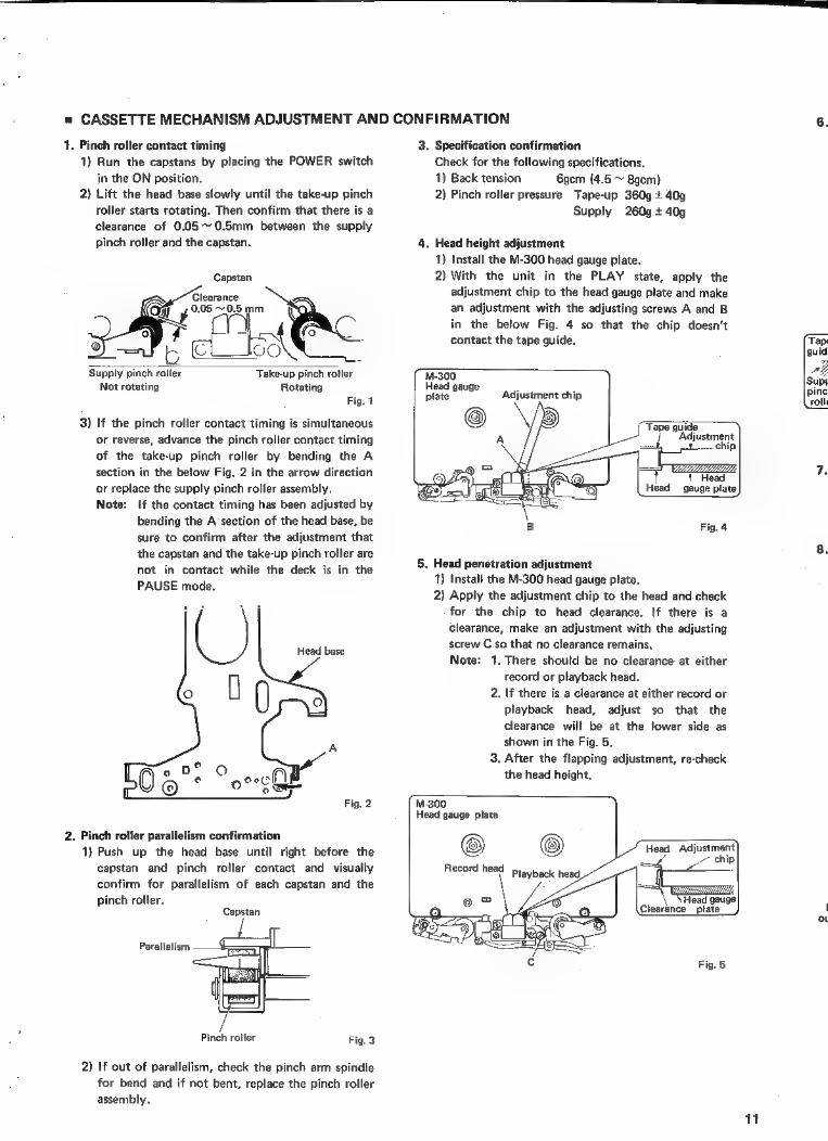
= CASSETTE MECHANISM ADJUSTMENT AND CONFIRMATION
1. Pinch roller contact timing 1) Run the capstans by placing the POWER switch
in the ON position. 2) Lift the head base slowly until the take-up pinch
roller starts rotating. Then confirm that there is a
clearance of 0.05~ 0.5mm between the supply
pinch roller and the capstan.
Capstan
Clearance fy 0.05 ~0.5 mm
5 LI} Ae @ 6 & OO Supply pinch roller Not rotating
Take-up pinch roller Rotating
Fig. 1
3) If the pinch roller contact timing is simultaneous
or reverse, advance the pinch roller contact timing
of the take-up pinch roller by bending the A
section in the below Fig. 2 in the arrow direction
or replace the supply pinch roller assembly. Note: {f the contact timing has been adjusted by
bending the A section of the head base, be
sure to confirm after the adjustment that
the capstan and the take-up pinch roller are
not in contact while the deck is in the
PAUSE mode.
Head base
Fig, 2
2. Pinch roller parallelism confirmation
1) Push up the head base until right before the
capstan and pinch roller contact and visually
confirm for parallelism of each capstan and the
pinch roller. Capstan
Parallelism
Pinch roller Fig. 3
2) If out of parallelism, check the pinch arm spindle
for bend and if not bent, replace the pinch roller
assembly.
3. Specification confirmation Check for the following specifications. 1) Back tension 6 gem (4.5 ~ 8gcm) 2) Pinch roller pressure Tape-up 360g + 40g
Supply 260g + 40g
4. Head height adjustment
1) Install the M-300 head gauge plate.
2) With the unit in the PLAY state, apply the
adjustment chip to the head gauge plate and make
an adjustment with the adjusting screws A and B
in the below Fig. 4 so that the chip doesn’t
contact the tape guide.
‘M-300 Head gauge plate Adjustment chip
Tape guide Adjustment
B Fig. 4
5. Head penetration adjustment 1) Install the M-300 head gauge plate.
2) Apply the adjustment chip to the head and check for the chip to head clearance. If there is a
clearance, make an adjustment with the adjusting
screw C so that no clearance remains. Note: 1. There should be no clearance at either
record or playback head. 2, If there is a clearance at either record or
playback head, adjust so that the
clearance will be at the lower side as
shown in the Fig. 5.
3. After the flapping adjustment, re-check
the head height.
M-300 Head gauge plate
Head Adjustment chip
WiLL ‘Head gauge
Clearance _plate
c Fig. 5
ahi

6. Supply pinch roller height adjustment
1) Install the M-300 head gauge plate.
2) Set the unit in the PLAY state. With the adjust-
ment chip applied to the tape guide of the supply
pinch roller, check the tape guide to chip clearance.
Make an adjustment with the adjusting screw D
in the below Fig. 6 so that the upper and lower
clearances become equal. 3) After the adjustment, repeat STOP-PLAY and re-
check the height.
D Fig. 6
7. Erase head flapping confirmation
As in step 5, visually check the erase head flapping. If
the clearance is large, make an adjustment by insert-
ing a spacer or replace the erase head.
8. Azimuth adjustment
When the maximum level point of R channel does not
equal that of L channel, connect the oscilloscope as
shown in Fig. 7 and proceed with azimuth adjust-
ment so that L and R channels are in phase.
a) Connect L channel tape out to “X(or V)” and R
channel to “‘Y (or H)"’. Observe the lissajouss wave- form.
b) Set L and R channels to monaural. Adjust vertical
and horizontal gain so that the waveform becomes 45 degree.
c) Adjust azimuth so that the measurement of “a” becomes maximum and the measurement of ‘b’””
becomes minimum against 45 degree line.
output output Fig. 7
9. Tape pass confirmation
1) With the mirror cassette (MC-109C without pad)
in the PLAY state, check the tape for snaking
or curling at the side.
2) Confirm by repeating PLAY-STOP more than twice. fe
© Contact or curling at the tape quide
Curling must be corrected but contact is accept-
able.
Watch carefully between the tape guide of the
pinch roller and the erase head as flapping tends to occur there.
© If flapping exists, perform checking as described
in the following 3) and on.
3) When the tape transport is unstable;
a. Re-adjust the supply pinch roller height as in
step 6. Then perform the azimuth adjustment as
in step 10 and check the tape transit. If the tape transit is satisfactory, check to ensure that the erase head height is proper.
b. If the pinch roller height adjustment can not correct the unstable tape transport, check each part for parallelism.
© Check the capstan spindle for tilt. If it has a
tilt, try tilting the record and playback heads
in the same direction.
® If the tape flapping exists right before the
erase head, eliminate it by tilting the erase
head with a spacer inserted A or B between
the erase head and erase head base as shown
in the Fig. 8. ® Check for parallelism of the tape guide of the
supply pinch roller and the capstan. If they
are not parallel, replace the supply pinch
roller assembly. @ Check for parallelism of the take-up pinch
roller and the capstan. If they are not parallel,
replace the take-up pinch roller assembly.
Note: Make sure to perform the azimuth adjustment after each adjustment and
then check the head height and flap-
ping.
Erase head
Erase head base
Fig. 8

13
TIMING CHART
1. STOP > F.FWD 2. STOP > REW.
REW. i =.
brew. ff
Met AMR
optay___! H ee.
RMUT o-nec..
bu __f
Cautions: 1. After AMR rises, the computer performs puls check and auto stop processing at F.FWD.
2. It performs auto stop and auto playback Processing.
3. STOP > SCAN F.FWD
eWOISCAN) —[———] relay
‘eewo___[ Turn onand off at 1H ReON Ky (One)
K; (ONL) ame j= ——-__4——
AMT onc.
Bu __t
Cautions: 1, After AMR rises, the computer performs puls check and auto stop processing at F.FWD.
2. After AMR rises, if the set is in scan F.FWD, the computer checks scan signal and performs queing processing.
Cautions: 1. After AMR rises, the computer performs puls check and auto stop processing at REW.
2. It performs auto stop and auto playback Processing.
4. STOP > SCAN REW.
EW. (SCAN) S71
tay rew.___[Tumon antral or
ey fowen) Ky font)
KfoN-u) we!
optay__
Mur onec.
ow
Cautions: 1. After AMR rises, the computer performs puls check and auto stop processing at F.FWD.
2. After AMR rises, if the set is in scan REW., the computer checks scan signal and performs queing processing.
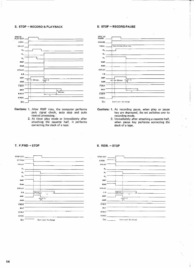
5. STOP > RECORD & PLAYBACK 6. STOP > RECORD-PAUSE
(Rec. 8
wes, beause
Ko. nf ry Ko [ie 2 en naa
Kr ut KL {
RMF a RMF ; 4
na ! run opLay__| OPLAY ‘ i
AMF i AME rn “1 “he 20msec. ee ris 20msec. 8 awn tt ii awa“ ni
ra : aa wrt} + wt —+4
MuT * 1 MuT +t - ity a it
bu __I bu Don’t care: No change
Cautions: 1. After RMF rises, the computer performs puls signal check, auto stop and auto rewind processing.
2. At timer play mode or immediately after attaching the cassette half, it performs correcting the slack of a tape.
7. F.FWD > STOP
Cautions: 1. At recording pause, when play or pause key are depressed, the set switches over to recording mode.
2. Immediately after attaching a cassette half, when pause key performs correcting the slack of a tape.
8. REW. > STOP
STOP KEY [== STOP KEY Cpl LeEWO 1 ‘LREW. 1
1eLay ———] beLcay
Ko iM Ko i
jee ee ee ig yt Le K ae % I
RMF ! ane cee
RMR AMR | !
OPLAY OPLAY :
£8 eB [Romsee——————) ame ame le ame aun Tr oo mut wor mut
aur aur one, once, Bu ——— bow care: No change ou Don't care: No change
14

TIMING CHART
1, STOP > F.FWD
A = 130 msec. B= 30 msec.
F.FWO beLay Leewo___f
Ko toneu___ Ot
a
AMR = 4
aMuT
‘onec. bu
Cautions: 1. After AMR rises, the computer performs puls check and auto stop processing at F.FWD.
2. It performs auto stop and auto playback processing.
3. STOP > SCAN F.FWD
F.FWDISCAN) bpLay LeFWo Turn on and off at TH?
Ky (ONL) —— i
2. STOP > REW.
Ko (ONL) Ky (ONL)
Ky ONeL) RM RMR
oPLay
AME aur f——. PMT
aMUT
o-nec. bw
Cautions: 1. After AMR rises, the computer performs puls check and auto stop processing at
REW. 2. It performs auto stop and auto playback
Processing.
4, STOP > SCAN REW.
REW. (SCAN) rpLay LEW, Torn on andl oft at We
wetONety
i}
Kitonty Kytonuy ao) tony
ee owe! a Ce
onay onay | ‘a a ae:
ame [ ame [1 ame Tre a 9 PMUT PMUT
wut ii emut cad. onee onec buf ou
Cautions: 1. After AMR rises, the computer performs puls check and auto stop processing at F.FWD,
2. After AMR rises, if the set is in scan F.FWD, the computer checks scan signal and performs queing processing.
13
Cautions: 1. After AMR rises, the computer performs puls check and auto stop processing at F.FWD.
2. After AMR rises, if the set is in scan REW., the computer checks scan signal and performs queing processing.
14
5. $1
(REC &) PLAY Kt Lae 1s
Cautic
7. Fil
STOP Ke Lev
bps
5. STOP > RECORD & PLAYBACK
(nec &) PLAY KEY L TREC, TPLAY
6. STOP > RECORD-PAUSE
(nec. 8) PAUSE PAUSE LaEC, wm on and off at THe,
Ky CS, ye
RMF z 1
Mai H awa 4 deta! i a ! es! \ esi '
ame | amet ann TT ree ae ame“ tomee HP mt 1 mG + ; a a sur : Se er amar —Tt “
out Du Dont care: No change
Cautions: 1. After RMF rises, the computer performs puls signal check, auto stop and auto rewind processing.
2. At timer play mode or immediately after attaching the cassette half, it performs
correcting the slack of a tape.
7. F,.FWD > STOP
‘STOP KEY 71 LFWD 1 rpLay
Ky
Cautions: 1. At recording pause, when play or pause key are depressed, the set switches over to recording mode.
2. Immediately after attaching a cassette half, when pause key performs correcting the slack of a tape.
8. REW. > STOP
STOP KEY ca LREW. 1 teLtay ——]
Ko M
Rh & — on ——
au ——]_ 3 awe ns: RMR M H ame i
oPLay i H o-PLay : ‘
ee [Ronee 3. ce {ore ————7). ante Foi ame ira ie ame i amr ap
amt PwOT mur mur
aur awur one. onec. BU —— bow’ ear: No change au Don't care: No change
14
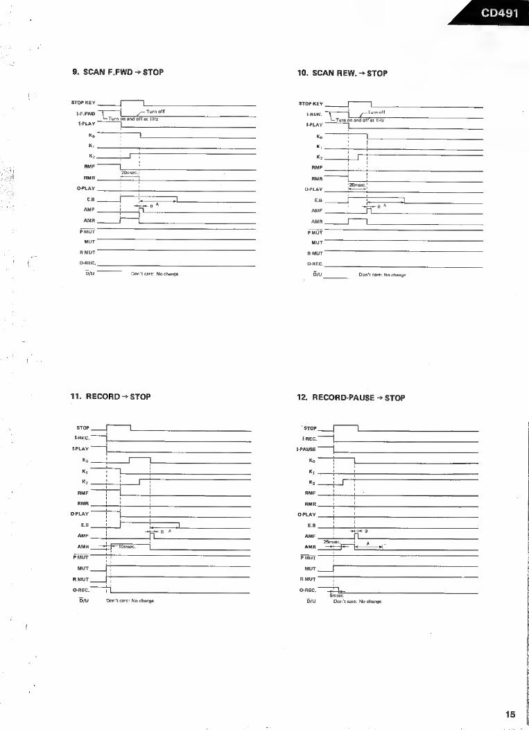
9. SCAN F.FWD > STOP 10. SCAN REW. > STOP
stop Key [=< stor KEY [=a Turn off yo staal LF FwO brew, “4 “umn oF ana SHR TRE ur oman oa TRE vetay ——Y tevay eT
Kee por Eon as Se eA « : x, vont a fe
rue ——_? AME ime: oa i FMR = AMR i aot \omsee
orLay ! i oPLay a
eB p =) ee — 1 z 1 ae AME Pee ne AME Fi AMR: I AMR
aUT amt mur mur
RMur Amur one. once,
Diy ———— bons care: No change bu on" care: No change
11. RECORD > STOP 12, RECORD-PAUSE > STOP
stor [JL rec. |
rpause ——|
bw Don't care: No change.
Rut ——t onc. 71
Brnsees Bu ‘Don’t care: No change
15

13. RECORD-PAUSE > RECORD 14, RECORD > RECORD-PAUSE
ray [1 Pause Key___[——] ¢ reLay vetav —4 = thee’ 1. nee. _[Tomenandovar tne race. rate SA ano
ip ee ae a oe
Rue 1} wn
OPLAY T I
: i — oe ane __ Bi (ae ee ee
H T maa wor __| : a a wut once, —t ote, — © aut au—1
Caution: After RMF rises, the computer performs puls check, auto stop and auto rewind processing.
© All sorts of operating mode and conditions of output signals (steady states)
oy [recay [1 ¢ [tpause | AMF | Mut DU C L L_ L H t H L | H L H L H L H u L H t e H 4 & L L t L H = L H t L L H = L L H L H L H
L H L L L L -
H HL L L H L L H H L H (
H L L L L H L H H L L :
H/L L H L H L H L H H H H; high level output transistor on L; low level output transistor off H/L; on/off at 1Hz 50% duty ‘© When it turns on and off from L, it starts from H. ‘© When it turns on and off from H, it starts from L. —: Holds the before state.
16
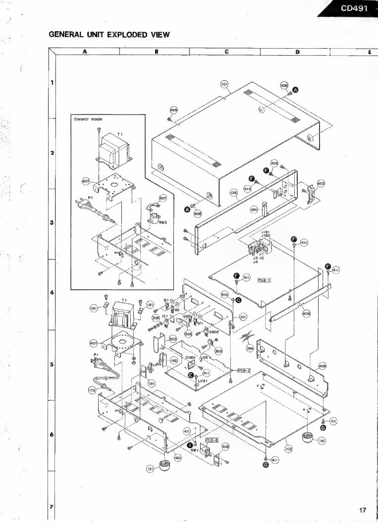
GENERAL UNIT EXPLODED VIEW
i
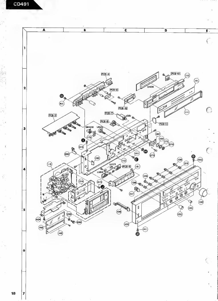
18

CASSETTE MECHANISM EXPLODED VIEW

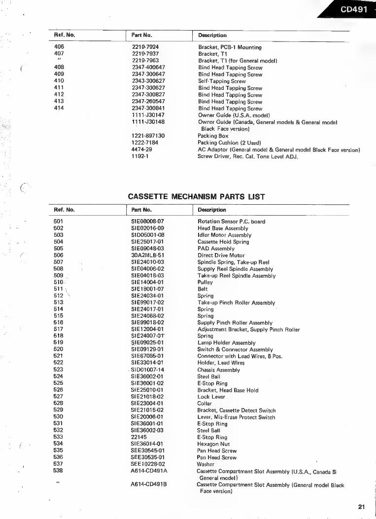
GENERAL UNIT PARTS LIST
Ref. No. Part No. Description SMe
. 101 A414-CD491A Cabinet Top Assembly
102 A424-CD491A Cabinet Bottom Assembly (U.S.A. & Canada models) ie A424-CD491B Cabinet Bottom Assembly (General model) _
me A424-CD491C Cabinet Bottom Assembly (General model Black Face version) ( 103 A443-CD491A Front Panel Assembly (U.S.A., Canada & General models)
ie A443-CD491C Front Panel Assembly (General model Black Face version) 104 A514-CD491A Plate Assembly
105 A630-CD491A Knob Assembly, Master Fader (U.S.A., Canada & General models) A630-CD491B Knob Assembly, Master Fader (General model Black Face version)
106 AG62-CD491A Push Button Assembly, Power 107 A662-CD491B Push Button Assembly, Rec. Mute, Auto Space 108 A662-CD491C Push Button Assembly, Reset, Time, Count, Memory,
Auto rewind/replay, Dolby NR, NR Type, MPX Filter, Bias/Equalization (METAL, CrO2, LN), Bias Tone, Rec. Cal, Timer (Play, Off, Rec.), Peak Hold,
20
Meter Weighting 109 A662-CD491D Push Button Assembly, Tape Monitor 110 A731-CD491A Indicator Holder Assembly 111 A443-CD491B Indicator Panel Assembly 112 B211-CD491A Chassis Assembly, Front
113 €112-CD491A Cassette Tape Recorder Mechanical Assembly (U.S.A., Canada & om General models) Co
™ C112-CD491B Cassette Tape Recorder Mechanical Assembly (General model Black Face version)
131 1319-0139 Foot
136 1424-09301 Cabinet Back (U.S.A. & Canada models) a 1424-09302 Cabinet Back (General model & General model Black Face version)
141 1513-04801 Plate 142 1513-05101 Dressing Plate (U.S.A.,Canada & General models)
" 1513-05102 Dressing Plate (General model Black Face version) ae 146 1531-05601 Cassette Compartment Cover
152 1630-01901 Knob, Output Level, Mic. Level, Rec. Level (U.S.A., Canada & ‘< General models)
ue A634-CD491A Knob Assembly, Output Level, Mic. Level, Rec. Level (Geneal
model Black Face version) 153 1634-02701 Knob, Bias Fine Trim (U.S.A., Canada & General models)
1634-02702 Knob, Bias Fine Trim (General mode] Black Face version) 155 1662-05501VN Push Button, Eject 161 3351-015 Push Button Assembly, Cassette Mechanism Control 169 2111-1356 Felt 172 2114-415027 Bushing
173 2114-72167 Bushing i 175 2132-7115 Spacer ‘ 180 2114-71254 Bushing 181 2219-7093 Bracket 182 2219-7809 Bracket 191 2224-7061 Insulator (Except General model & General model Black Face version) 192 2240-7118 Holder (Except General model & General model Black Face version) 198 2240-7120 Holder 215 2651-2101705 Spring 220 2674-7013 Slider | 235 2114-01224 Bushing
236 2310-7025 Special Screw 270 2440-61 Special Nut 273 2459-3003511 Rivet 301 2222-7147 Heat Sink : 302 2222-7151 Heat Sink ! 303 2222-7067 Heat Sink 305 2114-71278 Bushing 306 2652-00309 Leaf Spring ( | 307 2440-7017 Special Nut (Except U.S.A. & Canada models) 7 f 401 2211-7238 Chassis, Left (U.S.A. & Canada models) i
a. 2211-7245 Chassis, Left (General model & General model Black Face version) é : 402 2219-7811 Bracket, SW1 #2“ 403 2219-7909 Bracket, Microphone Jack 404 2219-7910 Bracket, Cassette Mechanism Bottom { 405 2219-7911 Bracket, Right
;
Ref. No. Part No. Description
406 2219-7924 Bracket, PCB-1 Mounting 407 2219-7937 Bracket, T1
ad 2219-7963 Bracket, T1 (for General model) ( 408 2347-400647 Bind Head Tapping Screw
409 2347-300647 Bind Head Tapping Screw 410 2343-300627 Self-Tapping Screw 4 2347-300627 Bind Head Tapping Screw 412 2347-300827 Bind Head Tapping Screw 413 2347-260547 Bind Head Tapping Screw 414 2347-300841 Bind Head Tapping Screw
1111-J30147 Owner Guide (U.S.A. model) 1111-J30148 Owner Guide (Canada, General models & General model
Black Face version) 1221-897130 Packing Box
1222-7184 Packing Cushion (2 Used)
4474-29 AC Adaptor (General model & General model Black Face version)
1192-1 Screw Driver, Rec. Cal. Tone Level ADJ.
CASSETTE MECHANISM PARTS LIST
Ref. No. Part No. Description
501 S1E08008-07 Rotation Sensor P.C. board 502 SIE02016-09 Head Base Assembly 503 $1D05001-08 Idler Motor Assembly 504 SIE25017-01 Cassette Hold Spring 505 S1E09048-03 PAD Assembly
‘a 506 30A2NLB-51 Direct Drive Motor 507 $1E24010-03 Spindle Spring, Take-up Reel 508 S1E04006-02 Supply Reel Spindle Assembly 509 $1E04018-03 Take-up Reel Spindle Assembly 510 SIE14004-01 Pulley 511, SIE18001-07 Belt 512 S1E24034.01 Spring 513 S1E99017-02 Take-up Pinch Roller Assembly 514 S1E24017-01 Spring 515 SIE24068-02 Spring 516 $1E99018-02 Supply Pinch Roller Assembly 517 SIE12004-01 Adjustment Bracket, Supply Pinch Roller 518 S1E24007-0T Spring 519 $1E09025-01 Lamp Holder Assembly 520 $1E09129-01 Switch & Connector Assembly 521 SIE67065-01 Connector with Lead Wires, 6 Pos. 522 S1E33014-01 Holder, Lead Wires 523 $1001007-14 Chassis Assembly 524 SIE36002-01 Steel Ball 525 SIE36001-02 E-Stop Ring 526 S1E25010-01 Bracket, Head Base Hold 527 SIE21018-02 Lock Lever 528 SIE23004-01 Collar 529 SIE21015-02 Bracket, Cassette Detect Switch 530 SIE20006-01 Lever, Mis-Erase Protect Switch 531 $S1E36001-01 E-Stop Ring 532 SIE36002-03 Steel Ball 533 22145, E-Stop Ring
/ 534 SIE36014-01 Hexagon Nut 535 SEE30545-01 Pan Head Screw 536 SEE30535-01 Pan Head Screw
. 537 SEE10228-02 Washer ; 538 A614-CD491A Cassette Compartment Slot Assembly (U.S.A., Canada &
General model) a A614-CD491B Cassette Compartment Slot Assembly (General model Black |
‘ Face version) |
a
22
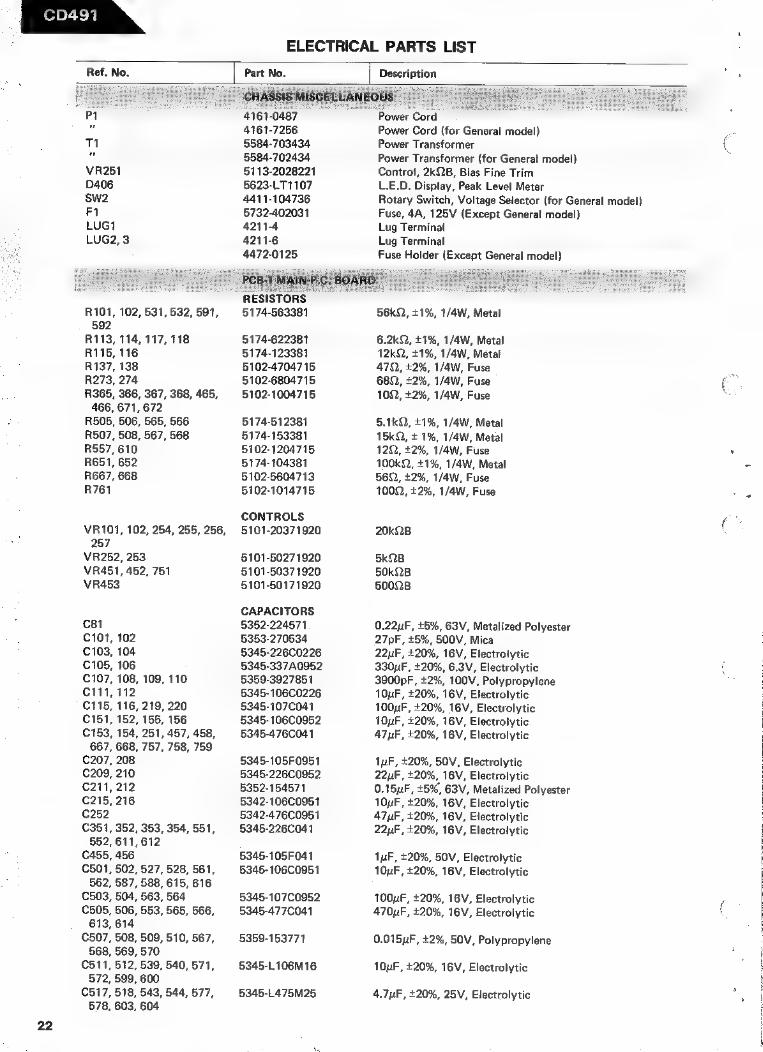
ELECTRICAL PARTS LIST
Part No.
VR251 D406 sw2 FA LUG1
LUG2, 3
R101, 102, 531, 532, 591, 592
R113, 114, 117, 118 R115, 116 R137, 138 R273, 274 R365, 366, 367, 368, 465, 466, 671, 672
R505, 506, 565, 566
R507, 508, 567, 568 R557, 610 R651, 652 R667, 668 R761
VR101, 102, 254, 255, 256, 257
VR252, 253 VR451, 452, 751 VR453
c8i C101, 102 C103, 104 C105, 106 C107, 108, 109, 110 C111, 112 C115, 116, 219, 220 C151, 152, 155, 156 C153, 154, 251, 457, 458, 667, 668, 757, 758, 759
C207, 208 C209, 210 €211, 212 C215, 216 C252 C351, 352, 353, 354, 551, 552, 611,612
C455, 456 C501, 502, 527, 528, 561,
562, 587, 588, 615, 616 C503, 504, 563, 564
C505, 506, 553, 565, 566, 613, 614
C507, 508, 509, 510, 567, 568, 569, 570
C511, 512, 539, 540, 571, 572, 599, 600
C517, 518, 543, 544, 577, 578, 603, 604
“RESISTORS
4161-0487 4161-7256
5584-703434 5584-702434 5113-2028221
5623-LT1107 4411-104736 5732-402031 4211-4
4211-6
4472-0125
5174-563381
5174-622381 5174-123381 5102-4704715 5102-6804715
5102-1004715
5174-512381
5174-153381 5102-1204715 5174-104381 5102-5604713
5102-1014715
CONTROLS 5101-20371920
5101-50271920
5101-50371920 5101-50171920
CAPACITORS 5352-224571 5353-270534
5345-226C0226 5345-337A0952 5359-3927851 5345-106C0226 5345-107C041 5345-106C0952 5345-476C041
5345-105F0951 5345-226C0952 5352-154571 5342-106C0951 5342-476C0951 5345-226C041
5345-105F041 5345-106C0951
5345-107C0952 5345-477C041
5359-153771
5345-L106M16
5345-L475M25,
Description
Power Cord Power Cord (for General model) Power Transformer Power Transformer (for General model) Control, 2kQB, Bias Fine Trim L.E.D. Display, Peak Level Meter
Rotary Switch, Voltage Selector (for General model) Fuse, 4A, 125V (Except General model) Lug Terminal Lug Terminal Fuse Holder (Except General model)
56kQ, +1%, 1/4W, Metal
6.2kQ, +1%, 1/4W, Metal 12kQ, +1%, 1/4W, Metal 47, £2%, 1/4W, Fuse 68Q,, +2%, 1/4W, Fuse 102, £2%, 1/4W, Fuse
5.1kQ, £1%, 1/4W, Metal
15kQ, + 1%, 1/4W, Metal 120, +2%, 1/4W, Fuse 100k, 1%, 1/4W, Metal 562, +2%, 1/4W, Fuse 10022, +2%, 1/4W, Fuse
20k2B
5kQB 50kQB 5002B
0.22uF, +5%, 63V, Metalized Polyester 27pF, #5%, 500V, Mica 22uF, +20%, 16V, Electrolytic 330uF, +20%, 6.3V, Electrolytic 3900pF, #2%, 100V, Polypropylene 10uF, +20%, 16V, Electrolytic 100pF, +20%, 16V, Electrolytic 10uF, +20%, 16V, Electrolytic 47uF , #20%, 16V, Electrolytic
1uF, £20%, 50V, Electrolytic 22uF, +20%, 16V, Electrolytic 0.15uF, +5%, 63V, Metalized Polyester 10uF, +20%, 16V, Electrolytic 47uF , £20%, 16V, Electrolytic 22uF , $20%, 16V, Electrolytic
1yF, +20%, 50V, Electrolytic
10uF, 20%, 16V, Electrolytic
100uF, 20%, 16V, Electrolytic 470uF, 20%, 16V, Electrolytic
0.015,F, +2%, 50V, Polypropylene
10uF, +20%, 16V, Electrolytic
4.7uF, #20%, 25V, Electrolytic
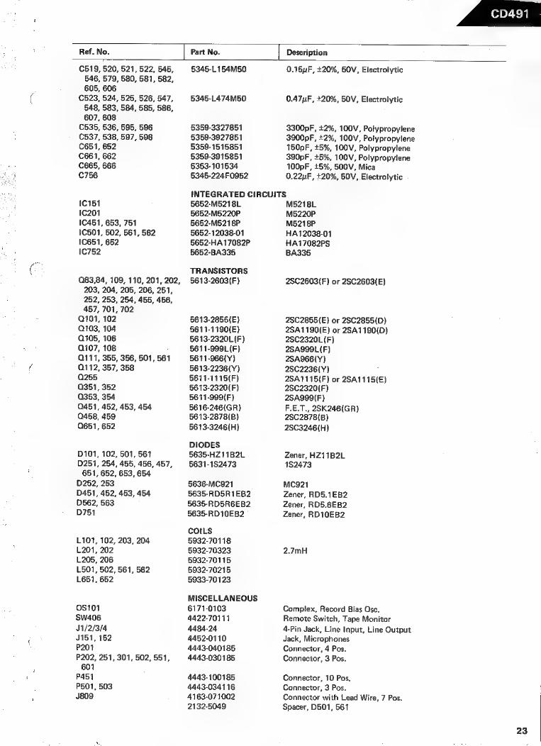
Ref. No. Part No. Deseription
C519, 520, 521, 522, 545, 546, 579, 580, 581, 582, 605, 606
C523, 524, 525, 526, 547, 548, 583, 584, 585, 586, 607, 608
C535, 536, 595, 596 C537, 538, 597, 598 C651, 652 C661, 662 C665, 666 C756
1C151 1C201 1C451, 653, 751 1C501, 502, 561, 562 1C651, 652 1C752
083,84, 109, 110, 201, 202, 203, 204, 205, 206, 251, 252, 253, 254, 455, 456, 457, 701, 702
Q101, 102 Q103, 104 Q105, 106 Q107, 108 Q111, 355, 356, 501, 561 Q112, 357, 358 0255
0351, 352 0353, 354 0451, 452, 453, 454 458, 459 651, 652
D101, 102, 501, 561 D251, 254, 455, 456, 457,
651, 652, 653, 654 D252, 253 D451, 452, 453, 454
D562, 563 D751
L101, 102, 203, 204 L201, 202 L205, 206
L501, 502, 561, 562 L651, 652
0s101 swa06 J1/2/3/4 J151, 152 P201 P202, 251, 301, 502, 551, 601
P451 P501, 503 J809
5345-L154M50
5345-L474M50
5359-3327851
0.15uF, +20%, 50V, Electrolytic
0.47pF, +20%, 50V, Electrolytic
3300pF, +2%, 100V, Polypropylene 5359-3927851 3900pF, +2%, 100V, Polypropylene 5359-1515851 150pF, +5%, 100V, Polypropylene 5359-3915851 390pF, +5%, 100V, Polypropylene 5353-101534 100pF, +5%, SOOV, Mica 5345-224F0952 0.22uF, +20%, 50V, Electrolytic
INTEGRATED CIRCUITS 5652-M5218L M5218L. 5652-M5220P M5220P
5652-M5218P M5218P 5652-12038-01 HA12038-01 §652-HA17082P HA17082PS 5652-BA335 BA335
TRANSISTORS
5613-2603(F) 28C2603(F) or 28C2603(E)
5613-2855(E) 2S8C2855(E) or 25C2855(D) 5611-1190(E) 2SA1190(E) or 2SA1190(D) 5613-2320L(F) 2SC2320L(F)
5611-999L(F) 2SA999L(F) 5611-966(Y) 2SA966(Y) 5613-2236(Y) 28C2236(Y) 5611-1115(F) 2SA1115(F) or 2SA1115(E) §613-2320(F) 2S8C2320(F) 5611-999(F) 2SA999(F) 5616-246(GR) F.E.T., 25K246(GR) 5613-2878(B) 28C2878(B) 5613-3246(H) 2SC3246(H)
DIODES
5635-HZ11B2L §631-1S2473
5636-MC921 5635-RD5R1EB2
5635-RD5R6EB2 5635-RD10EB2
COILS 5932-70116
5932-70323 5932-70115
5932-70215 5933-70123
MISCELLANEOUS
6171-0103 4422-70111
4484-24
4452-0110 4443-040185, 4443-030185
4443-100185 4443-034116 4163-071002 2132-5049
Zener, HZ11B2L 182473
mcg21
Zener, RDS.1EB2 Zener, RDS.6EB2 Zener, RD1OEB2
2.7mH
Complex, Record Bias Osc. Remote Switch, Tape Monitor
4-Pin Jack, Line Input, Line Output Jack, Microphones Connector, 4 Pos. Connector, 3 Pos.
Connector, 10 Pos. Connector, 3 Pos. Connector with Lead Wire, 7 Pos. Spacer, D501, 561
23

RESISTORS , R20, 27 5102-4R74713 4.7, £2%, 1/4W, Fuse Zz
CAPACITORS €
c3 5345-478D0962 A700LF, +20%, 25V, Electrolytic c4 5345-228D041 2200uF, +20%, 25V, Electrolytic C5, 6, 11, 13, 51 5345-477C041 470uF, +20%, 16V, Electrolytic c7 5341-109D0958 10000uF, +20%, 25V, Electrolytic C8, 9 5352-684571 0.68uF, +5%, 63V, Metalized Polyester C14 5345-107C041 100uF, +20%, 16V, Electrolytic C52 5345-476D041 47uF, +20%, 25V, Electrolytic
C53 5345-475D041 4.7uF, 20%, 25V, Electrolytic
C54 5345-106D041 10puF , +20%, 25V, Electrolytic C802 5342-475D0951 A.7pF, 420%, 25V, Electrolytic c901 5345-474F041 0.47uF, +20%, 50V, Electrolytic
INTEGRATED CIRCUITS 1c1 5653-T78012AP TA78012AP 1C801 5653-BA6109 BA6109
(C851 5654-58846-41 M58846-641SP_ ae 1C852 5654-TD62503P TD62503P € P 1¢901 5654-TC4001BP TC4001BP °
TRANSISTORS
Q1,9 §611-1217(Y) 28A1217(Y) Q2,11 5613-2877(Y) 2SC2877(Y) - a3 5616-2SK381(D F.E.T., 2SK381(D) = 4, 10, 807, 851, 852,853, 5611-1115(F) 2SA1115(F) or 2SA1115(E) 854, 855, 856, 903, 905 ¢
Q5, 801, 802, 803, 808, 809 5613-3246(H) 2SC3246(H) Q6, 812, 813 §611-1286(H) 2SA1286(H) C> Q7, 8, 12, 13, 804, 805, 806, 5613-2603(F) 2SC2603(F) or 2SC2603(E) . 810, 811, 857, 901, 904
051, 91,94 5611-1115(E) 52, 92, 93 5613-2603(E) 3902 5611-1305(Y)
DIODES D1,2 5632-1SR35-10 D3 5685-1F
04,5 5635-RD9R1EB2 D6 5635-RD8R2EB1
D8, 9 5641-KB265 D10 5635-RD12EB1
D51,55,56,57,58,59,90,91, 92, 93, 95, 96, 97, 98, 801, 802, 805, 806, 808, 809, 810, 856, 859, 860, 861, 862, 863, 864, 865, 866, 873, 902, 903, 904
D52 5635-RD13EB2
5631-1S2473
053, 54 5631-1S2471 D803 5635-RD8R2EB3
D804 5635-RD6R2EB2 D807 5635-RD4R7EB2
24
2SA1115(E) or 2SA1115(F) 2SC2603(E) or 2SC2603(F) 2SA1305(Y)
1SR35-10 Bridge Silicon, SIRBA Zener, RD9.1EB2 Zener, RD8.2EB1 { Varistor, KB265 or MV-12 Zener, RD12EB1 182473
Zener, RD13EB2 182471 Zener, RD8.2EB3
Zener, RD6.2EB2 Zener, RD4.7EB2
| |

Ref. No. Part No. Description
MISCELLANEOUS
X851 5693-CSB457 Crystal, Ose. F2,3 5732-402031 Fuse, 4A, 125V = 5732-40202 Fuse, 4A, 250V (for General model)
P801 4443-067114 Connector, 6 Pos. P802 4443-107114 Connector, 10 Pos. P803 4443-097114 Connector, 9 Pos. P804 4443-030185 Connector, 3 Pos. P805 4443-080185 Connector, 8 Pos.
P806 4443-050185 Connector, 5 Pos. P807 4443-060185 Connector, 6 Pos. P808 4443-104116 Connector, 10 Pos. P809 4443-074116 Connector, 7 Pos.
4472-414 Fuse Holder (x4) 2132-7048 Spacer, R13, 810, 811, 832, 835, D1, 2,6 2132-7049 Spacer, R20, 27, 836, 837 2132-5049 Spacer, R833, 834
R191, 192 R428
VR151/152 VR161, 162 VR301/302 VR401, 402
C161, 162 C163, 164 C165, 166 C167, 168 C169, 170 C171, 172 C177, 178, 413, 414 C403, 404 C405, 406 411, 412 C415
1C401
Q81, 82 Q161, 162, 165, 166 Q163, 164
Q167, 168, 169, 170, 401, 402, 403, 404, 405, 406 407
D161, 162 D401, 402, 403, 404 D405 D701
LC161, 162
$W301/302 P401 J402 J501 J503
5102-1814715 5173-270571
CONTROLS 5113-20371140 5113-2038321
5113-5027F40 5101-20371920
CAPACITORS 5345-106C0952 5359-2215851 5345-106C0951
5359-1015851 5345-226C0951
5359-1025851 5345-476C041
§345-475D041 5345-335F041 5345-226C041
5345-227C041
INTEGRATED CIRCUIT §652-M5218P
TRANSISTORS 56 13-2878(B) 5613-2320L(F) 5611-999L(F) 5613-2603(F)
5613-2236(Y)
DIODES 5635-RD10EB2 5631-1K34A §635-RD7R5EB2 5631-1S2473
MISCELLANEOUS
5214-51 4431-02047364
4443-070185 4163-072002 4163-70296 4163-70396 2132-5049
a 1802, +2%, 1/4W, Fuse 270, +5%, 2W, Metal
20kQA, Mic Level 20kQA, Rec Level Left/Right 5kQA, Output Level 20k2B
10uF, +20%, 16V, Electrolytic 220pF, #5%, 100V, Polypropylene 10uF, +20%, 16V, Electrolytic 100pF,, #5%, 100V, Polypropylene 22uF,, +20%, 16V, Electrolytic 1000pF, +5%, 100V, Polypropylene 47uF , £20%, 16V, Electrolytic 4.7uF, 420%, 25V, Electrolytic 3.3uF, $20%, 5OV, Electrolytic 22uF,, +20%, 16V, Electrolytic 220yF, +20%, 16V, Electrolytic
M5218P
2SC2878(B) 2S8C2320L(F) 2SA999L(F) 2SC2603(F)
28C2236(Y)
Zener, RD10EB2 1K34A Zener, RD7.5EB2 182473
LC Components
Push Switch, Rec Mute, Auto Space
Connector, 7 Pos. Connector with Lead Wire, 7 Pos. Connector with Lead Wire, 3 Pos, Connector with Lead Wire, 3 Pos. Spacer, R425
25

Ref. No. Part No. Description 7 Si
D201, 202, 203, 204, 205, §631-182473 182473 206, 411, 867, 868, 869, 3 ¢ 870, 872
D409 §637-GL5HD22 . L.E.D., GL5HD22, Red, Tape Monitor
MISCELLANEOUS
$W201, 202, 203, 401,402, 4431-0918716 . Push Switch, Bias/Equalization, Dolby NR/Type, MPX 403, 801, 802, 803 Filter, Timer
$W204, 205, 901,902,903 4431-A027136 Push Switch, Peak Hold, Meter Weighting, Memory, Auto Rewind/Replay
$W404, 405, 904,905,906 4431-A027236 Push Switch, Bias Tone, Rec. Cal, Reset, Time, Count J803 4163-094502 Connector with Lead Wire, 9 Pos.
2132-01401 Spacer, D409
D851 5637-SY406TK D852 5637-TLR122 .E.! on D853, 854, 855 5637-TLG121 L.E.D., TLG121, Green, F.FWD, Play, Rew. Ree D857, 858 5631-1$2473 182473
MISCELLANEOUS $W101, 102, 103, 104, 105, 4431-A017140 Push Switch, Rew, Play, F.FWD, Stop, Record, Pause 106
'VR163/164
:, Hea phones
Capacitor, 0.01uF, +100% —0%, AC125V, Ceramic 5361-1030419 5352-1030958 Capacitor, 0.01uF, 20%, AC250V, Metalized Polyester
(for General model) swt 4431-A01056 Push Switch, Power f
VR201, 202
| oo
D407 5637-GL9PG19 D408 5637-GLOHY9 L.E.D., GLOHY9, Vallone Dolby C
“LP802 Camiguin
: ae PCB: E .C. BOAL : 906 5613-2603(E) Transistor, 28C2603(E) or 28C2603(F) D905 5637-LT9002D L.E.D., LT9002D, Red, Wait f
DSP901 5623-SLK2452 LED Display
J808 # 4163-101802 Connector with Lead Wire, 10 Pos.
her aap olf 220A o Dileee Dirve bet* S€€ 21 54Fe/ 1 =~
26
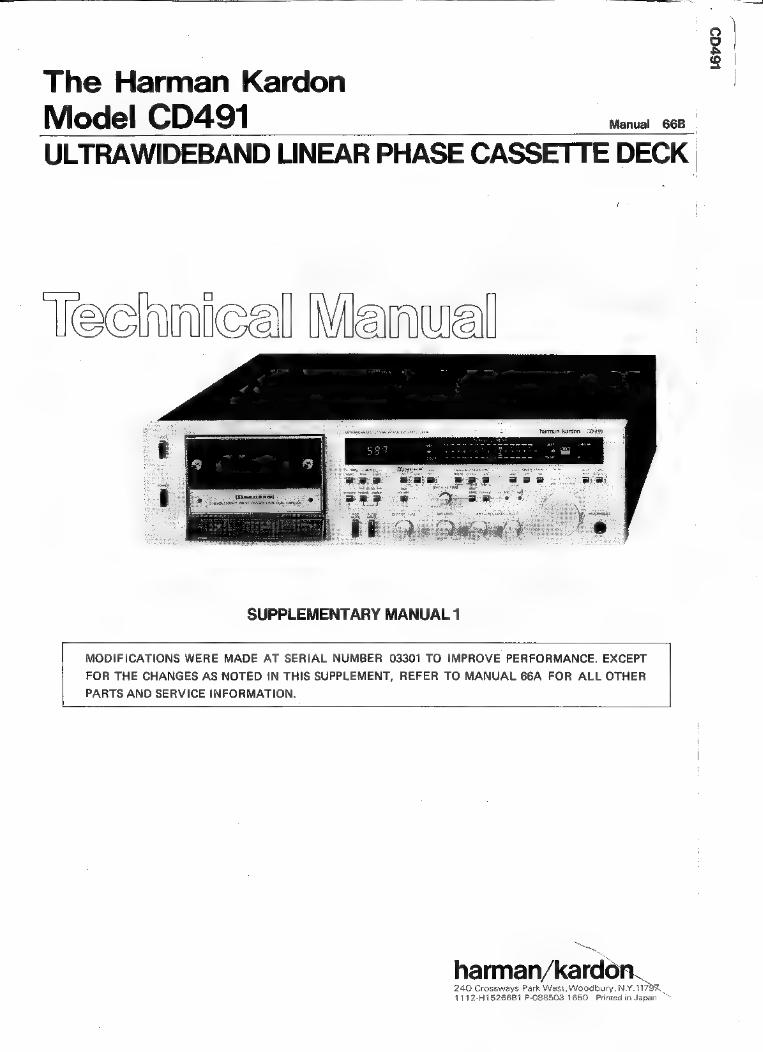
The Harman Kardon
Model CD491 Manual 66B_
ULTRAWIDEBAND LINEAR PHASE CASSETTE DECK
:
echnical Manual
SUPPLEMENTARY MANUAL 1
MODIFICATIONS WERE MADE AT SERIAL NUMBER 03301 TO IMPROVE PERFORMANCE. EXCEPT
FOR THE CHANGES AS NOTED IN THIS SUPPLEMENT, REFER TO MANUAL 66A FOR ALL OTHER
PARTS AND SERVICE INFORMATION.
harman/ kardon 240 Crossways Park West, Woodbury. NY.1179% 1112-H15266B1 P-088503 1650 Printed in Japan ~~
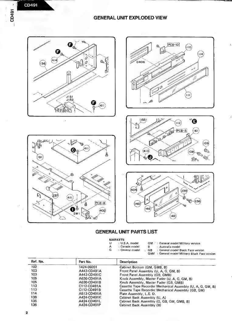
GENERAL UNIT EXPLODED VIEW
GENERAL UNIT PARTS LIST
MARKETS UF US.A. model GM — : General model Military version A jamodel BB _~—_: Australia model G —: General model © GB_: General model Black Face version
GBM : General mode! Military Black Face version
Ref. No. Part No. Description
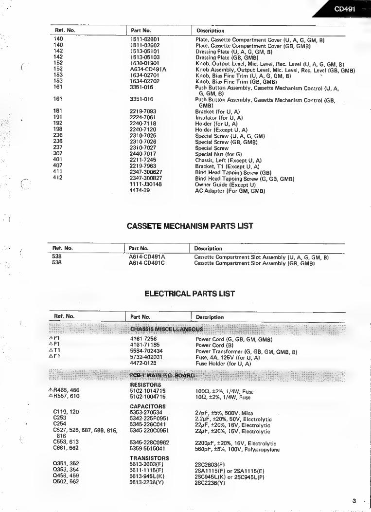
102 1424-09201 Cabinet Bottom (GM, GMB, B) 103 A443-CD491A Front Panel Assembly (U, A, G, GM, B) 103 A443-CD491C Front Panel Assembly (GB, GMB) 105 AG30-CD491A Knob Assembly, Master Fader (U, A, G, GM, B) 105 A630-CD491B Knob Assembly, Master Fader (GB, GMB) 113 C112-CD491A Cassette Tape Recorder Mechanical Assembly (U, A, G, GM, B) 113 C112-CD491B Cassette Tape Recorder Mechanical Assembly (GB, GM) 114 AS13-CD491A Plate Assembly, L.E. D. 136 A424-CD491K Cabinet Back Assembly (U, A) 136 A424-CD491L. Cabinet Back Assembly (G, GB, GM, GMB, B) 136 A424-CD491P Cabinet Back Assembly (B)
Ref. No. Part No. Description
140 7511-02601 Plate, Cassette Compartment Cover (U, A, G, GM, B) 140 1511-02602 Plate, Cassette Compartment Cover (GB, GMB) 142 1513-05101 Dressing Plate (U, A, G, GM, B) 142 1513-05103 Dressing Plate (GB, GMB) 152 1630-01901 Knob, Output Level, Mic. Level, Rec. Level (U, A, G, GM, B) 152 A634-CD491A Knob Assembly, Output Level, Mic. Level, Rec. Level (G8, GMB) 153 1634-02701 Knob, Bias Fine Trim (U, A, G, GM, B) 153 1634-02702 Knob, Bias Fine Trim (GB, GMB) 161 3351-015 Push Button Assembly, Cassette Mechanism Control (U, A,
G, GM, B) 161 3351-016 Push Button Assembly, Cassette Mechanism Control (GB,
GMB) 181 2219-7093 Bracket (for U, A) 191 2224-7061 Insulator (for U, A) 192 2240-7118 Holder (for U, A) 198 2240-7120 Holder (Except U, A) 236 2310-7025 Special Screw (U, A, G, GM) 236 2310-7026 Special Screw (GB, GMB) 237 2310-7027 Special Screw 307 2440-7017 Special Nut (for G) 401 2211-7248 Chassis, Left (Except U, A) 407 2219-7963 Bracket, T1 (Except U, A) au 2347-300627 Bind Head Tapping Screw (GB) 412 2347-300827 Bind Head Tapping Screw (G, GB, GMB)
1111-30148 Owner Guide (Except U) 4474-29 AC Adaptor (For GM, GMB)
CASSETE MECHANISM PARTS LIST
Ref. No. Part No. Description 538 ‘A614-CD491A Cassette Compartment Slot Assembly (U, A, G, GM, B) 538 ‘A614-CD491C Cassette Compartment Slot Assembly (GB, GMB)
ELECTRICAL PARTS LIST
Ref. No. Part No. | Description
ta _ GHASSIS MISCE ve A i API 4161-7256 Power Cord (G, GB, GM, GMB) AP 4161-71185 Power Cord (B) AT 5584-702434 Power Transformer (G, GB, GM, GMB, B) AFI 5732-402031 Fuse, 4A, 125V (for U, A)
4472-0125 Fuse Holder (for U, A)
AR465, 466 R557, 610
C119, 120 C253 C254 C527, 528, 587, 588, 615, 616
C553, 613 C661, 662
0361, 352 0353, 354 0458, 459 0502, 562
RESISTORS 5102-1014715 5102-1004715 CAPACITORS 5353-270534 5342-225F0951 5345-226C041 5345-226C0951
5345-228C0962 5359-5615041
TRANSISTORS 5613-2603(F) 5611-1115(F) 5613-945L(K) 5613-2236(Y)
100, +2%, 1/4W, Fuse 1002, +2%, 1/4W, Fuse
27pF, 5%, 500V, Mica 2.2uF, 20%, SOV, Electrolytic 22uF, +20%, 16V, Electrolytic 22uF, t20%, 16V, Electrolytic
2200uF, +20%, 16V, Electrolytic 560pF, +5%, 100V, Polypropylene
2S8C2603(F) 2SA1115(F) or 2SA1115(E) 2SC945L(K) or 2SC945L(P) 2SC2236(Y)

Ref. No. Part No. Description
DIODES D103, 104, 502, 5641-KB265 Varistor, KB265 564
D255 5631-1S2473 182473 D562, 563 5635-RD5RGJB2 Zener, RDS.6JB2 D751 5635-RD11JB2 Zener, RD11JB2
COILS L201, 202 5932-70223 3.3mH L751 5597-35502 Ferrite Bead
MISCELLANEOUS J1/2/3/4 4484-24 4-Pin Jack, Input, Output (U.S.A., Canada & General
models) J1/2/3/4 4484-41 4-Pin Jack, Input, Output (General model Black Face &
General model Military Black Face versions) P301, 502, 551, 601 4443-037114 Connector, 3 Pos.
C4 C52 C53 C863
D4,5 D6 D10 D11 D803 D804 D807
L851
VR151/152 VR301/302
081, 82
D161, 162 D405
J502 J551
VR163/164 J601
J301
ACI
D407 D408
_ PCB:
CAPACITORS 5345-478D0962 5345-475D041 5345-476D041 5345-226C0951
DIODES 5635-RDOR 1JB2 5635-RD8R2JB1 5635-RD12JB1 5631-1S2473 5635-RD8R2JB3 5635-RD6R2JB2 5635-RD4R7JB2
MISCELLANEOUS 5597-35502
CONTROLS 5113-50272140
5113-50271150 TRANSISTORS 5613-945L (K)
DIODES 5635-RD10JB2 5635-RD7R5JB2
MISCELLANEOUS 4163-70696 4163-70796
PCE.6 MAS) 5113-10397122 4163-70496
HEADPHO! 4163-70596
PCBS POWER § 5352-1030958
5637-GLOHY9 5637-GLOPG19
ITCH P.c. BOARD
4700uF, + 20%, 25V, Electrolytic 4.7pF, +20%, 25V, Electrolytic 47uF, £20%, 25V, Electrolytic 22uF, +20%, 16V, Electrolytic
Zener, RD9.1JB2 Zener, RD8.2JB1 Zener, RD12JB1 182473 Zener, RD8.2JB3 Zener, RD6.2JB2 Zener, RD4.7JB2
Ferrite Bead
5SkQA, Mic. Level 5kQA, Output Level
2SC945L(K) or 2SC945L(P)
Zener, RD10JB2 Zener, RD7.5JB2
Connector with Lead Wire, 3 Pos. Connector with Lead Wire, 3 Pos.
BOARD
Control, 10kQA, Master Fader Connector with Lead Wire, 3 Pos.
SUA OAR ! Connector with Lead Wire, 3 Pos.
Capacitor, O.01uE, 420%, AC250V, Metalized Polyester (Except U.S.A. & Canada models}
ICATORS PCB
LE.D., GLeHYe, Yellow, Dolby NR Cc L.E.D., GL9PG19, Green, Dolby NR B
A SAFETY RELATED COMPONENT. USE ONLY EXACT REPLACEMENT PART AS SPECIFIED.

A B c D E F G H i) J K L M N ° P
SCHEMATIC DIAGRAM ee oe oy
A a A —— . PEAK LEVEL METER ee a ) Sa SS SS SS OE : ——— a == r PLAYBACK AMP DOLBY NR SECTION (PLAYBACK i eee = ee ae =
1 | -- H ape atari HEADPHONE 16401 on | I i 1 AMP. mz emnica 7 H | Faas = 1 F) a "7 a L 2snogery) 1 r. Saas Tad 18, PAE asserts oa fl $4 0403 Miek 5 | r ay 0 RAO BEN AL I ita i 1 DH SRE BRS I & rsav2sasecr yes’ i £ T i are cru ngge -J- 45 | Sas] % 1 Tape tet 33 3 I I I eee S48 I 4 Heal ser sg i Be errata] I 3] 8e/= I aay wR | 383 zereuu | 470 1 t| 1 fextere Qi07 = See g ¢351,c353| # I a ROI
gPiol I |2SAS99L (F) bat
n gap | ALAYBACK | [ am 8 1 Trev) Tg BR SR BB ody 08% 1 [are 3 Been? 1 fon ON [orev I r 9103 Stim Ter oEa 32 iJ IC501 HAI2038-01 ' ie Gass rt E [ele 2700 =| aa
mos 28A1190 Ay. ¢] 8 | S7V 5.1V 5.8V SIV S7V Ooev 0.97V 0.87V o02v 1 Shit ty ERS a403 ely Tr cio 220 (Ee) sous oni ye [Se SA, Se ae eee (Fore) 5 = | [vec] S8C2s0 IF) G { eur eis One mA 1 1 oe ze iq I aes jarv cnr Peg cso 1 actten| Ml =o wer 1¢401 Minors 3 x mt a ey (Kor?) ae: ernie ynenanee| M5218P iment| soge 1
ie SE 3 atts tke Tiseass Y vonean [er] [ages] 3x 247/80 I ii i > 2198. 882 2cosdhoxrs sex | J] | sex di BIAS LEVEL ABS I oni. 2 LI 2 it cz) Wl re ie 55 i RECORD, PLAYBACK | i oy 8 ole to
| } 102 MP. 3 ic uel be i ri i | EQUALIZER FREQUENCY | r2co 27x | PLAYBACK 2sc2ess pare Ps 1 , FARACTER | i HEAD ane, i osce 1 oh 28C2236() i § i i | one =1s tse | ; ee zi 4 if i 3 s[e Tee = BO swadpiz) uf | ey | I [ade 3 Sele tape
SRR 3 878 moni fi j ae g 2 1 ese i i - a ele |e2° cs I
Ey zene | 1 Nae a H 2SC2603(E)oKF) i #¢ us i s) |S 8 | [From 182473 4, | uy als : I a a8 Ee [ + i a eRe 9354 y as EW ee rrr?
1 Meise. fod | lERERPESZso3:rIorve) o S it
ae 1c502 HA12038-01 I aeceasl i ESE gi ascaaseiige: 2 ! Nears wt) I
ahs By Be i > TAUTD BEARGG ao]
gered \ | 1 1 [AUTO SEARCH ADJ. 1 — eet Gas | Sw205 sw204 | oe | eat
|} 0 swaos 2) : :5C2603 (Forte) 0255 nave 1 yemeter peak Mite 1 | | 2392, tape Bye = BIAS LEVEL ADJ. a 473. 1oK | i Le eenntingy fale ae 1 rere r 33 & Bee's r]
A 1] LOBE ayy [To Tape wonivor “lee RECORD// PLAYBACK ae ‘| | Rees 1 r nl 1 | 1s Indleator_10409) EQUALIZER FREQUENCY ] Paka A 1] CHARACTERISTIC AD | ee3 far [ate i] ! I ae cnnsc ac sys ie ! 1 H
H H a
| Dae i H ' 1 meee i LU = gm (1P20! J35I I % -———————— [OC CF =o Navies © BIAS TRAP ADJ.]
A[]HeaopHones [BIAS TRAP H Cl e 8b TEN as ‘aa I LU 5S e201 aaa orc R233 3.9K, . R761 100 10.0V ¥T. 28 — 7 i ! Mt 4 1 pares it E a a orl lar get ly i ay H n frrferv | 3 3 2 ' Bi ‘3 27 Is00P Si] i t== { 2 [ee 8 8 cv_| 2 1 el2 aa I Eee ale ——
ersa | ia n fe Tso ses ; ajororm 838 TSTEP UR TRANS ADJ] I TP751 = @—p Ht iad | nl nee 33K i arm. ge read thE i STEP UP Les! ‘ay 9651
ee ee 1e752 ! aK o SanenL ae eas TRANS ADJ. id Neer te ©, Rios coe Ere BA335, Li 318 atx 3 coos bine i ie @ 3 8x8 a B38 ‘i Rly tn [oi] the ra ‘S60P ln2a0 TP252|
| LI eis a a) 8) aye EGORP || Se 302011 | o203 M | Zaso [noes 2 ga \” ~ asceeos [2sce6o3 |esc26o3tr dorie) he 5 AL ERASE
t SCAN AMP. a = L 1¢561 HAI2038-01 Labs. asceeos | ascaso: i J 3 [ee | os I © HEAD l = Ev sz Siv Sy Av srvs2v_ av cozy cosy oagy vey aay H pennah bet ie ise A Ape Nair ede ! ; f= a 1 Feel + © foes RECORD /PLAYBACK I t { I i Tei ov vi LINE & MIC. , nes: =| brid ae EQUALIZER ea 1 wogie. [dei aug ie doar Y Tovene [ego] [ages E ERAS egy ] mY CHARAGTERISTIC i r] é oi Aria roo AMP. 1 oT TO ake R oes oo cave nzoe ARASaEoe Ic651 Ic651 Iees3
spe cis! Aneel | SlBes I6ooe 20K ! Len Al7Os2Ps HAI7OB2PS| Ms218P cist osIgLL) Age i" | s gle S18Te 3 ho g borsrzm ie a
| iss vec] sas Bas eile 5 Bag” Rz06. D651, 182473, 1.cav [sav 1 iaav vist Boss Z orien Ba3 B¥5 eles s 2 8785 nZ0 sls
eps at, q aye g £)888 33 po arama of H ghe ava awl cert “LL RIS] iss | te
& 3 ‘gear shot ao SiG I J ots 2 4» LEFT ue 01 We gooey RI79 [| 2SA966(Y) R202 SysTo lease aast a acta I 0.011 a
o.civ PT azox' fit 562 sew ive io g SLZa rer2 AN = mex FcreR y s a a= eee eres do I & ye : ae a fone lee j regan
MICROPHONES es TOE o S—Tat wears e] aTeeee e 3 ig HEAD 5f &) (C). [312 CP ' 28 [2 alge HE }S[ L ECORI aa 8 3 I Sra é pe le ' els Seite fleets yh ever a {ed HEE: I [STEP UP TRANS ADI] =o cama oie Ee oase 4 ool SF S| eta eos i JADJ. asczso3 |2sca6o3| |2sc2sosir iorte) d eae ree aes ate aie 1 wr scout)" ee a (Le ai sae oY, ‘Fiee) | Fer) | £5701 192473 +4 Revo _ cess 6 ogee: ner eee
= 100F og ti eeee 1 = > i 385 S| Zenit.) RECORD LEVEL ADJ. = “ ial i vO FR
i is otk Yaa, 852 35 ea __1l_ & gt te fj stl 5 bie 1 3 a 2 19 6 16 1S ee 1 RECORD/PLAYBACK e-7 Fe 3 o7s oe : wat2oae-o} P. —|ewedoends t J SU mea orig ‘28028201 ells t ECORDING AMP. CHARACTERISTIC. i os vo eine ee i Sy ae = i) ie 3h [8 4S 1 : 78 | LG | — = =
m x i. Reet 1a Aa RE Tress > ‘ : iro |E | aud ia ak le ~ ele els Bo wena 23k e2g s28hy = a 3
1c652 1c652 1c653 i = &Fe gis er vorreney [see Rees ge gs eee i ° o 6 Reh HA17082PS HaI7082PS| M5218P Rare @ EST BS Tass [5
2473 1 , acs | ales Pe B35] cs a sls dese, “ r i sh nies 2sa999L iF) | 2sc2320L $a S#3| ex ry
8qs els olsun 7 > | bar 87s] 882010] Sk sw302 SW30! sy: H 348 a t) K) acts ‘| 2 eye = AUTO SPACE REC MUTE one eT SE 58 82x 23 Bee le gy 3 calms | HE HE &
u ee Wels : S e on* y Perr te ET EL ET TET ETT Ptr rir bepesdaseeeeeens Reapers s a es SO NO SS NO OH
aE TA7BOI2ZAP
FREC. CAL. & BIAS TONE OSC. wat H a) gS sexidibon os Soma I pacsioowrm 16451 MS218P ! i | ¢ + $}— - - ——— - - ————__ -- ——_——_- = r I RDS.1EB2 1 FA PERE E! rs} § 3 ; (Sac eS SAIS A
I » pass D451 D453, ‘fs i ; Ei He 7} | * za eee Cer wait 2 152473 To. Po I §. = eK Te 0451~ 454 | <a |
T4v is ® ia ov Ss a) *reeese 5, os! Ba 2Skoaeten | f il edt ae ae 3 P ioc i 2 451 1S H , She 07 I 1 z 7 [esse act Begs Len our se i a feaazal F Py aye 2Sc2603F or te) H
Vso OOK = cs sey aH @ i ie a sere, gueers |_| # :
aa ‘Ra6T tle
WALT | l 0455 [2 <RAbR LOOKS] 1 ‘ae iff a me z g p ice52 ine 7 eaten /FE[ eg 14 z Tab S2acos tek | |g — Te] | B8eS-SeB Re em " piesa 1 t i (rorte) ottee Te oth f B35 ‘92675 | $88 Bi pee 152473] SepasEen 2Ec2608 : m= te TT, : . fre eaene rc HEY Heo 1 ig Rac
sv 2 g [Bias “i 1 wls
(fares) a Hi i
a, TOOK OF fierle@) — ae02 wks wy | [ee ca] 8A" TONE || oass esenaourl, ' : ie Ka seen P| | [cw stneese-2 ! 1 TONE cs
cot 1
LEVEL | 1¢451 MS2I18P RD5.1EB82 Bak leon Mut rec} : 1 ee t _ ese iF tats pee 1 rr \ R468 lg 2 ef BS, 8 geiee, ws SE2%g 488 oe : geskieis I
Hn a . ne ee Mel] |Usbtt || |b uire, ay, 08K a Le aie eS rosa 3 ier apa 325 Joos! some enon ena. I | Sie | 7 je ¥ 5 Ssauis \| shy et 28C2603(F) artE) Bsc2e7rv) 1 : BS H wl Pl? * 2 ieee Swi iorte) \! & £T8) a1 I ae ce { con & 3 Iswi0S REC 2SC260R1F onE) 2SAIZI7WY)g, i Ly cage casa 100k 1 ' oe p08 ° eee SHS lob oo I i 1 I | [aee ca] ra00r $Ex i200r re IS me Ws2478 ia vol Pome" as 3 swi04 STOP he 1 (a7 1
priv z ox | | raza eal a ei bs stor 38 G 3 a 1 a ¢ Wire |B ae” Slaets few ~PAGIOg ae Bal savior al a | aS | | Borg |e] ee Brees) a sho Tess sere 8 Sher ree i] \ oBTEE FE bo eo : oasis zi lswioe PLAY Icgo! Tc4001BP I I 1 = i cea " wold F em oe ie ;
9457 i i so |RO4.7082 ere 1 Ecos te[| sa & I L ues aes -- a9 1 ae 0606 @ ae A 1 Ss ai escecos is ot fe I To Peak Level Cereea_—([ eaisttre RMR Lay SP ts2ar H ae
Meter Drive Sk dex D803 RDS.2uB3.
Sweo2tle) OFF | ' Circuit
B5f Tes 804 RDE.2uB2 Slewr sw Dae7 AUTO tox . ed yeeera’ f° a | replay Re ES 4 857 ie , i ‘SW903 A
= ‘0807 9808 9809 8x: 3882603 sweoi| TF wo I oY _ y—Selby'S 2SAINISIFIOrE) 2SC3246(H) _ 2SC3246(H) nese is® (Fior(e) Sates ay = roel u 088, 182473 escza7ny) . w20; = By jozoa* is2a7s i = acted ba lon se [22 sweozteor rf ny I 3 aio bet st So o Fs Don lift elt ¢
2Sainis 182473 38) B-—oo = ie 28ebbos | | Sts a rus 81 opee rewind (hort) H | [Fe 0205] Dolby C 3 oe (Forte) alo B $2473 jaa 7_|sweoz i moa avox 055 182473 A053 ! 3 joey Sy naar a
Ee ‘sw4o4 ‘swa05, sw4ol swaos | fo5208] * wt Th W803 REC 0670 182471 bias rec DOLBY mpx [re paes Ey Fs ° Mn a a os fork 8.6K an 8.6K Ki] Ise 182473 g ! g fone cal NR ve filter ct ama | ° cess ‘Le ome Fy A memory ete |y se at (tee 83 y e810 8 Hho af 8] | Sses7 2SC2603 2 t__} if ier boas slo Sw801 I I 2 H asi Thase scan] |aer™ Rose ass (952 25¢2603Florte) H el. fate Bex ean | a A ° 3 sw203 sw202 sw2or ! 812,013 i aoe we jeremy aa] slg ae | 8 887 Serrmar) I LN croz METAL 2saize6in H | owe @urece 906 see
1 i ae 2SC260R(F lor(E) I
1 BIAS / EQUALIZATION i : 1 r a
Bsansieioney sears iH POWER SUPPLY __ ry yy a et Tr ae a A oo
MICRO COMPUTER CONTROLLED PROCESSER BLOCK De Ne eR Re ee Ae ee Be A ee eee he Ne ee eee eee ae eee
RECORDING SIGNAL (Lch)
PLAYBACK SIGNAL (Reh)
HX-PRO SIGNAL
1. ALL RESISTANCES VALUES ARE IN Q. kQ= 10002,. MQ= 1000k2
THE WATTAGE OF RESISTORS IS 1/4W UNLESS OTHERWISE NOTED. ALL CAPACITANCES VALUES ARE IN uF UNLESS OTHERWISE NOTED. P = uyF AND ALL ELECTRICAL CAPACITANCES VOLTAGE VALUES ARE GIVEN WITHOUT UNIT. THE OMITTED UNIT IS V. 47/50 >47yF/50V
4, V: DC VOLTAGE AT NO SIGNAL. ...V STOP MODE
V|PLAYBACK MODE V) RECORDING MODE
5. A SAFETY-REQUIREMENTS COMPONENTS IN ACCORDANCE WITH PRESENT SAFETY. REGULATIONS. THESE COMPONENTS MUST ONLY BE REPLACED BY ORIGINAL PARTS. 5:
SS
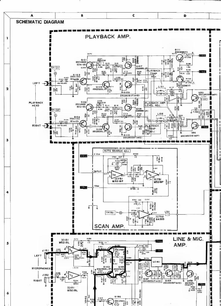
7 | SCHEMATIC DIAGRAM
P loaleteeloelalelenteeierieeleeleeleelelelenieeneeneieneioienis mabe
H PLAYBACK AMP. 7 f
t | 1
i an i I BrOgEN) A vary ees i
21, 2 1 rizo | HLAYBACK <r (B 1
4 t 20h 28 Saas FTES Lu cigy 3 Seas) ok 1
LEFT r foe 033 Eaten,
= i ee Fe z BUBasein i
Ll | # a108 H H 28¢a603 Fron) :
q PLAYBACK Q102
wean SD : 22M 62K ur, glo8 ile
ng e422 [eve : asyge ge te er), 5
RIGHT 22/16 (AR)
e102 ke | R102 sex 2SC2603(E INF)
poo L.-n==
Ici51 ms2iaL
are
leat leslie |
AUTO. SEARCH ADJ
== [= amar}
rs~o—
SCAN AMP.
167. 28c26031For(E) ase cons
Rare
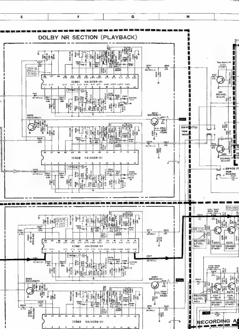
a DOLBY NR SECTION (PLAYBACK) i
ote — a i ‘
! Ef Bx f f PRE CGC | i i #7 ge T8 EL gere 873 1 § i
239 4 Bie . I & Safer epee ger 083 a J
a wean [| tt J 1 ee ae ee ig i wel | ell 1 Oh ah oh eh oblvolh ah WW ah ON eye ' ae an
1C50! HAI2038-01 5 fa tl s1v sav 87y Sev. B7V 87V O0RY O97V 067 ocx
res 0 te H P| |
eso 3 ea i ascoas. | Hl rehewn [eet Tags alter ar \ | wt be , ‘sex | J] 56K | BFS C3 z
Bl) BS) ade als g a Li || 5] eles vs i j
asc2 asndeetyy i 28cz2s6t1 wseessr | ae
Bs. mid 1 ar pa z ! (awadgevey UT Be
1 ® |ole 3 tape ‘gk 1 8 Fy mont Daa aye
mae i aK eee eG rt
vere | oY
zs # i a: i Sh zscoasi (Fre
. | ‘iort) L
soz ye i | od o swaos 12 z tape
HO/16 (LL) i ] s- monitor
i 1 I eg
a UW i
—— == ries ‘ 88 (BN Hl =s F
case) 5 i te re feteey| 3 ' Sbisia /abte e[s.0v Hy 1 Er [78
2 gers ees ca i den | %
ols § als |s 27 2 2 24 2 22 2 2 i9 8 ‘7 16 1 8 bly * « SSB eras Gee Sen ae ee 2 RECORD | 82% 0201] -| o20s
Ic56! HAI2038-OF JADJ. 28C2603 | 2Sc2603 s1v s7v rv 57v Sv SV a02v os6v oeev ao sav 1 (Prontey [Forced
7 7 TI “Meg cse7
erred weds loses |e Tere I “it
47k ‘56K f, c20g R208 1 3 5 matt Seer foe 2
2 Rao] eeK Eo
Ba i BE esetiox 3 Caso
1c562 HAI2038-01
563 ors cs wore
ey oe at fasczso3 |2scz6o3 fFlone) | (Forte) | 3

PEAK LEVEL METER
mre gg
(
4y2SA9661Y, aS avi a
ea f AMP. Ic401 MS218P CH
27 wa Raol_ 00NV 5) 403
BIAS CEVEL-AD:
RECORD/ PLAYBACK EQUALIZER FREQUENC’ Ra60 27K
— EET Tove Wonitor Ingleator_ (0409)
ioe
2sainseSeiey 132473
ee Vee5T
B
Siow
2 eS eZ03tF tor te)
3SC2603 (F )or(E) 0255 ners Bary
& - RECORD/PLAYBACK EQUALIZER FREQUENCY CHARACTERISTIC AD.
% BIAS LEVEL ADJ. ape "ok
[Bias TONE | pags’ fon [orev Fa lorr|-o2zv)e 3% e407 gy 200° fan aE Rais aor LS
ev 9243 a0 BIAS TRAP ADJ.
‘STEP UP TRANS ADJ.
RECORD -CEVEL ADL &
RECORD /PLAYBACK EQUALIZER FREQUENCY CHARACTERISTIC
| MS220P
azo te
270K
[From Dau)
pipiamnrn From Ia ERB yse47s =
1 ro {02081 182473
sw205
Bi Rett : L 4
sw204 '
‘2S C2603 Jor(E) Fo701 182473
| eS RECORD LEVEL ADL
oe oe ole ee oo he L
ark Tov
ISTEP UP TRANS (STEP. UR TRAN} RSTO cose
f 47k 100P
nese

$493, aos "Sk
e407 "9408 $280 2SER8301 Te iis wa
(ow Jarev"|
[uaiac waging oR 5 tnyorey 5 Tussi] 0.08 fz
METER LEVEL ADM.
jeaas BG) ws
ve et
a a TT
cara Ae
i D406 PEAK LEVEL,
METER
Leh
ouTPuT
J351
a []#ea0PHones
P UR TRANS ADJ. wiv 968! ascszaciin
4
RECORD HEAD
{o> RIGHT

10)
W
EC. CAL. & BIAS TONE OSC. = reesioowrm ‘C451 MS218P
a a 5. GL] ae we
bast 182473 g 3 i
4 i
aes Loh out] 130%
(mee. car_] [x_eriv Ore Lt
Inara om
rad oe 19K 9457 28C2603(FIor(E)
To Peak Level Meter Drive Gireult
2 z ' ool) & gi
| el = bead ieee a 2
swaos | oon | mpx 3
7 filter J a
: —Tt_3t) 5 \ 2 sw203 sw202 sw2oi |
LN croz METAL BIAS / EQUALIZATION

_— HE cee i a
vreau sea 3 wlan 1
ei slges ° 3
aE Acad Itt 2 bib
$302 SW30!
L AUTO SPACE REC MUTE
wut] scan I fe
i
o92 i 2 Tee52 5 tS eax 1sdeF escesos £ 3% Ret ; aes 091 (erorie) [OR 3) 8) pes 1s2473|
Psaltis Is H fehorc
1 i" ¥ o8or Te eause] D96 oe e
MECHA 2 ur vee} 5
mot ire PO S 3 S i fy reser 4 Ea She ut
t 28CSeaeun) Es {for ruse| 1 soe a 133473 = bh ° oz rec
ala 73 Fore a ooo sige ||| Fs
1 P54 567 89 10 8% Oqew air hee > oe: 3 >. Feralsby
(re [o.2v| Cebit {Moc xin FE Leal mato i | ivew . us xo 0806 =o 7S PLAY ' = aaa ascesos S38
FFor Rew, revi] 9805 pete): ee new PS Were eFWd_ 2sczeosie rane) nue (Frorrelira, eis SrK awe puny ase
2 80s ROS 25S re 0804. ROS.2J82 pee
37 ewe sa ‘O507 28068 @809 x: 28e2eos | 2saiTtBiFrente) 2Seszeeun 2sGEeecn gases | EST AFI Die,
7 Z iw | o yl ig 2 5%: ai | Janes elie) Btls | “4 ete |e = asio) IPoortE) alg = russ:
we Sp—2Alen ve 3 S vss vo]
| geo 1c851 Z5casos Ms8846-6415P or
: 3is3_ Ba 3 iai *UL
! MICRO CO

SS: Ae Sie ee Fd Ce eras sey —
Ices2 nalrossrs _nairoaep:
as 1gea7s STS
a ee
os = 25 25A1286(H) 13 c
at sl al al & : ie? lo F ise eee on
wait Eee ws2a73 [oly 2 TeV ig 283 J = sy LTS002H iA Res m 5 r. y osten C4
a) eyFLs 2SC2603(F Jor (E) z 1
2 | pes2 tuRI22 Ba9s~e50 Tisi21 2s icas2 __ isaars ey 957,858 2scasos E JTD62503P_ : 192473 Forel
sev 902
2SAI305(¥) wera
6 s70/16 132473
‘swacatle) OFF | D867. AUTO I
+s Segre al i replay swo03 i swool 98 PF I
PLAY = | pg69 loa sweo2%orF ir | is2473 I
-o ‘AUTO os ieee tS. rewind ] lst qjsweoe H
sweo3 REC 0870 1 lee 182473
7 ed I aie SwO0), I A z I Ci Lreoe 906 sw2 ? tains) |
1 Qa51~s56 pe59~866 | 2SAIIIF Dore 182473 POWER SUPPLY
IMPUTER CONTROLLED PROCESSER BLOCK
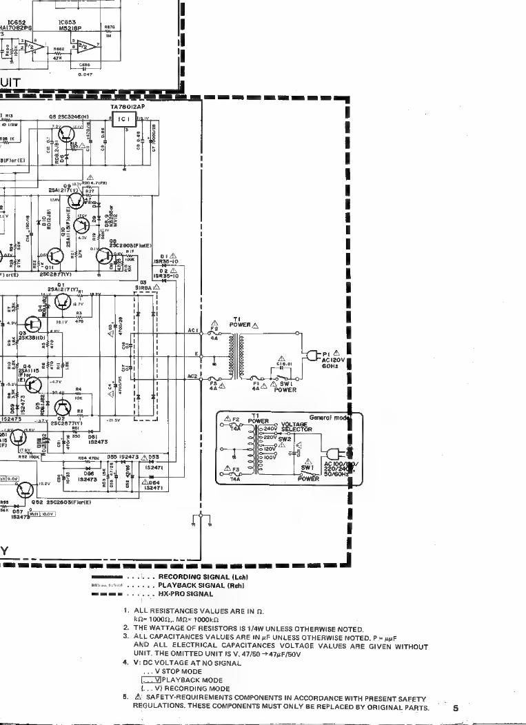
Ices2 1Al7082PS) 3
ee
a At. Tox
8 Re ont “aay astzer7) poe wd
a +2330 Ost 18 5 a Be are 1s2473 ney, °S ea toon] gro 055 152673 DSS
g is2471
3 +4 woav ® Anse in 182471
RECORDING SIGNAL (Lch)
PLAYBACK SIGNAL (Rch) HX-PRO SIGNAL
. ALL RESISTANCES VALUES ARE IN 9. kQ= 10002. M2= 1000k2
. THE WATTAGE OF RESISTORS IS 1/4W UNLESS OTHERWISE NOTED. ALL CAPACITANCES VALUES ARE IN xF UNLESS OTHERWISE NOTED. P = wuF AND ALL ELECTRICAL CAPACITANCES VOLTAGE VALUES ARE GIVEN WITHOUT UNIT. THE OMITTED UNIT IS V, 47/50 > 47uF/50V V: DC VOLTAGE AT NO SIGNAL
...V STOP MODE [="VIPLAYBACK MODE
V) RECORDING MODE A\ SAFETY-REQUIREMENTS COMPONENTS IN ACCORDANCE WITH PRESENT SAFETY. REGULATIONS, THESE COMPONENTS MUST ONLY BE REPLACED BY ORIGINAL PARTS. 5

A B c D £ F G H I J K L M N ° P
WIRING DIAGRAM a
1
—
BIAS LEVEL ADJ. General model
y t To PCB-2=———o RECORD / PLAYBACK EQUALIZER FREQUENCY CHARACTERISTIC ADJ. PUT INPUT MICROPHONES
PCB-I JULEFT LEFT JIS! 2 J2 RIGHT RIGHT JI52
VR251 BIAS FINE TRIM
> VOLTAGE ver SELECTOR
Pl AC 100/120 /220/240V PI 50/60Hz Ke ioe.
3 60Hz
ZS USO.
SG
4 TP203 fk
5 PEAKING com, ADJ. .
RECORD /1 PLAYBACK EQUALIZER FREQUE! CHARACTERISTIC ADJ.
D.D.MOTOR , CAPSTAN
6
esp D: iy Ren ivan ren tateees = = = more A ST a aT
LPso! ee CASSETTE =) LLUMINATOR
~
7
MIS-ERASE PROTECT
£ ROTATION SENSOR P.C. BOARD SWITCH ERASE HEAD DOLBY B-C NR BIAS/ EQUALIZATION —TIMER— impx meter
METAL CrO2_ LN play off rec weighting —TAPE COUNTER— 0: 5 reset time count
Sw904 Sws05 S
CASSETTE PACK 4
DETECT 8 SWITCH gy
war, DC MOTOR, REEL ear ee ee :
SW90I Sw902 SW903 4 sw404 sw405 memory —AUTO— tape moniter bias tone reccal
rewind replay i Lrepeat i
PCB-5 : : : | Pattern Side : — PCB-3 METER LEVEL Ry |
| PCB-II
9 |
! ' HT
} | TLLUMINATION
PCB-5 PCB-9 3
Parts Side 7 ear
i bee 5 c al en 3
- & war: : i : linet 8 RECORD LEVEL ADJ. H ey Swiol SWl02_— SWI03 swioa | SWI05 — SWI06 \ sw302 SW301 jet right D406 PEAK LEVEL METER PCB-10] odoLey NR
REW PLAY F.FWO STOP RECORD PAUSE Mou LEFT MIC LEVEL OUTPUT . AUTO REC rec cal MASTER J351 10) AUTO SEARCH AUTO SEARCH —REC LEVEL — LEVEL SPACE MUTE FADER HEADPHONES
| \ i
i i
if | ;
| WIRE COLOR ABBREVIATIONS : Red
PIN CONNECTION DIAGRAM OF TRANSISTORS, DIODES AND ICs.
WwW ‘2SA999 28C2236 RD8.2EB83 26! LT9002D TA78012AP_ | HA17082PS_—_| BAS35 TC4001BP TD62503P 28C2603 2SA966 fl f
2SA1286 28C3246 . : Purple E e : Pink
Zp 18R35-10 8 4 6 ce RD8.2EB1 1 4
RD12EB1 2SA999L 182473 RD13EB2 GL5HD22 GL9PG10 TLR122 M5220? M58846-641SP 2SA1115 RDS.1EB2 ee MR | GLOHYS 4g | TLG121 M5218? 2SA1190 RD9.1EB2 cothode Cathode 28C2320 HZ11B2L Zanose | cotove ee 2SC2320L RDS.6EB2 ‘anode te’ 2802855 e¢ RDIOEB2 ey wa 8 28C2878 182471 er DI0E Anode we
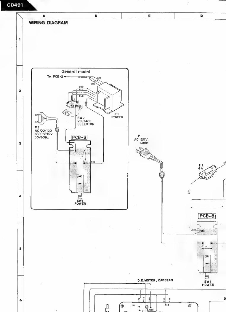
A | B ¢ D
WIRING DIAGRAM
1
General model To PCB-2 «———-
2
er ACI00/120 /220/240V Pn
50/60Hz “aC20Y;
3 60Hz
BZ <2 L AZ
@)
4
5
D.D.MOTOR , CAPSTAN
6 D
@

PCB-2
ete, Bulow ma a 1
ey D>) 3E 4 i
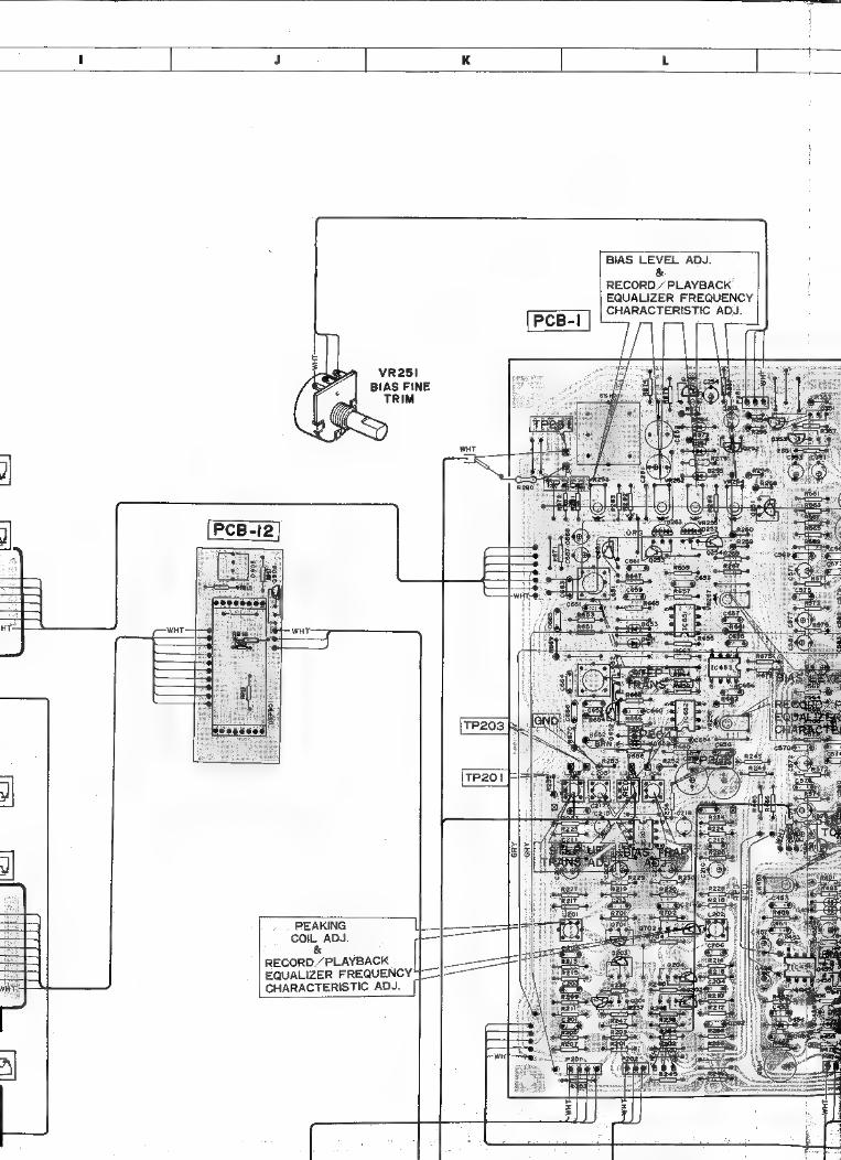
BIAS LEVEL ADJ. &
RECORD / PLAYBACK EQUALIZER FREQUENCY CHARACTERISTIC ADJ.
PCB-|
VR251 BIAS FINE
TRIM
PEAKING | COIL ADJ. _
& RECORD / PLAYBACK EQUALIZER FREQUENCY }——
CHARACTERISTIC ADJ.
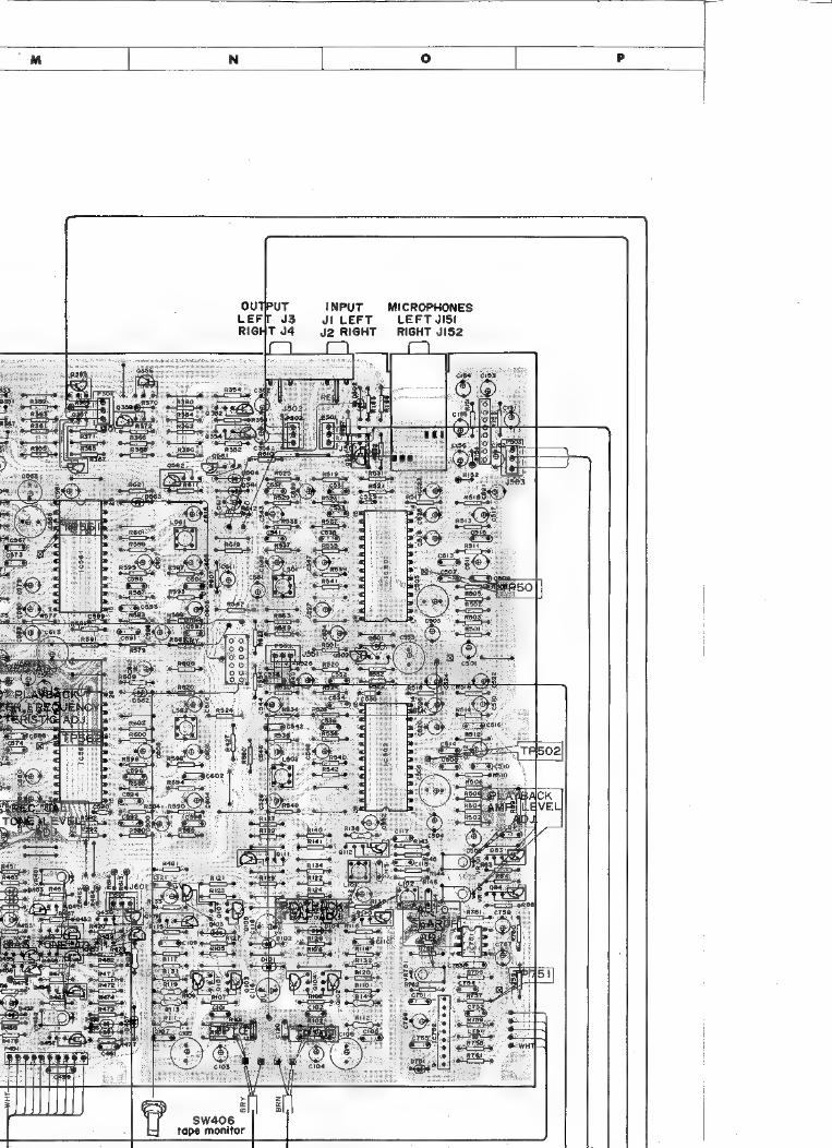
INPUT MICROPHONES Jt LEFT LEFT Jist J2 RIGHT RIGHT JI52
z si Sw406
tape monitor

pousDD Oe
PF GAHEIO 01946719 ** cause
HONV]ES OLAV
Maa
JOIMS
apis $140d $-99d
OPIS Usa} Og
G-89d
HOLIMS 493130 woVd
ailassv>
193.1L0ud asv4a-SIW
LLves a gy, 8L879SZ za30t0u zaag’sau Ta LiZH 7931'6du zearsay
eLv7st Lgensz 9vZ>SZ
LLBZOSTZ €932'80u LtZLwsz
“S01 GNV SAGOIG ‘SHOLSISNVYUL 3O WWHDVIC NOILLOANNOO Nid
GuVOE ‘D‘d YOSN3S NOILVLON
‘1a34 ‘YOLOW 94
EET)
we z
dng MOLVNIWNTT 3LL3SSVS
1o8d7
oL
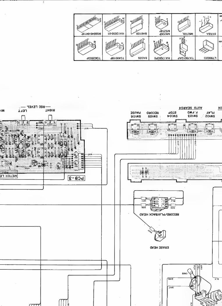
iat at HOYV3S OLN ‘HO
3SNVd = aHyoo3y dOls R 901MS SOIMS. | vOIMS
MA" Avid £0IMS = ZOIMS.
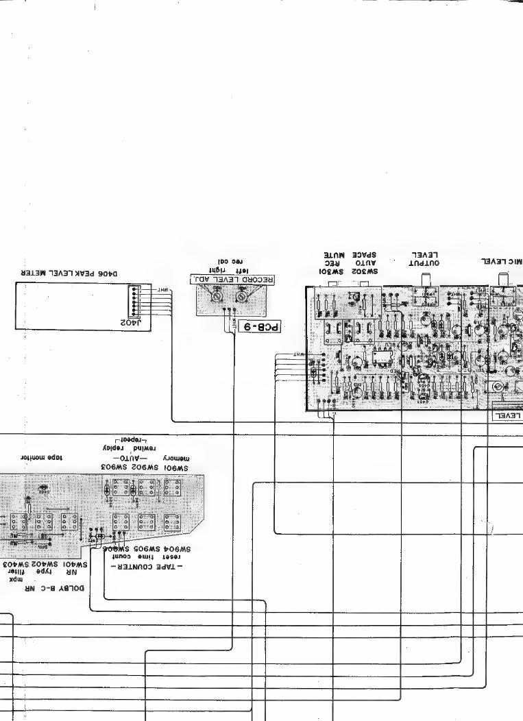
[09 9a1 4614 ager ¥3LBW 1337 Nv3d 9060 TOY TaASA) CHOOSE
Pp
BLAN 30VdS o3u olny
1O€MS ZOEMS
73431 1ndino 13A37 OIN
“AH
rioedes— Apides = pulmes
dojjuow edoy —Olnv— = Asowew £06MS ZOGMS 106MS
iS SO6MS POGMS juno eu, 19801
0bMS ZOPMS IObMS -4BLNNOD BavL— deus 9d} UN xdu
uN 9-@ AB10G
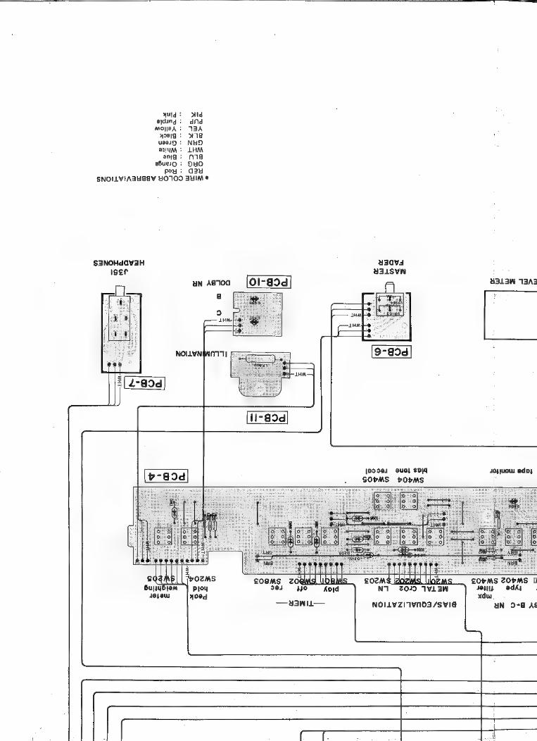
uid ¢ aiding : MolieA eld uaal5 UUM anig :
aBueid : SHO pay: O3Y
SNOILVIASUSEV YO109 SHIM ®
S3NOHdGV3H
iser
un astoa §=|Ol- 9d
a ]
2
NOLLVNEANT1
sf HM.
II-89d
uaava
y3LSVW
A
109902 euo} sD1q SObMS +vObMS
Y3L3W 13A3
4ojjuow adpy
HO
—¥83WiL—
Aoid Oem:
NT 2049 1VL3W
NOILVZITVNOS/SVIE
€OVMS.ZOPMS | sous odky ; xdu
UN 9-8 AE
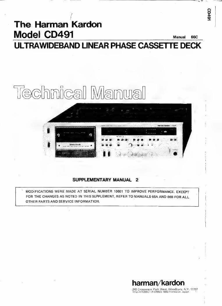
l6rdo
The Harman Kardon
Model CD491 Manual 66C
ULTRAWIDEBAND LINEAR PHASE CASSETTE DECK
echnical Manual
SUPPLEMENTARY MANUAL 2
MODIFICATIONS WERE MADE AT SERIAL NUMBER 10601 TO IMPROVE PERFORMANCE. EXCEPT
FOR THE CHANGES AS NOTED IN THIS SUPPLEMENT, REFER TO MANUALS 66A AND 668 FOR ALL
OTHER PARTS AND SERVICE INFORMATION.
harman/kardon 240 Crossways Park West, Woodbury, N.Y. 11797 1172-H18266C1 P-078503 1650 Printed in Japan
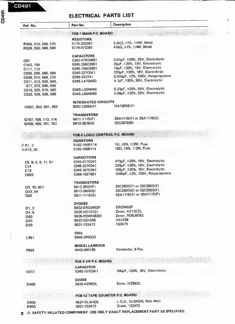
cD491
ELECTRICAL PARTS LIST
Ref. No. Part No. Description
R509, 510, 569, 570 R529, 530, 589, 590
cat C103, 104 C111, 112 C505, 506, 565, 566 C509, 510, 569, 570 C511, 512, 539, 540, 571, 572, 599, 600
C519, 520, 579, 580 C525, 526, 585, 586
1C501, 502, 561, 562
Q107, 108, 113, 114 0458, 459, 701, 702
AR1,2 AR13, 20
C5, 6, 8,9, 11, 51 c14 c18 C863
Q3, 10, 907 053,54 ag2
D1,2 D4,5 Deo D63 p99
L851
P803
C417
D405
D905 D906
PCB-1 MAIN P.C. BOARD. ih
RESISTORS 5174-332381 3.3kQ, £1%, 1/4W, Metal 5174-473381 47kQ., £1%, 1/4W, Metal
CAPACITORS §342-475D0951, 0.47uF, +20%, 25V, Electrolytic 5345-226C0951 22uF , #20%, 16V, Electrolytic 5345-106C0951 10uF , £20%, 16V, Electrolytic 5345-227C041 220uF, +20%, 16V, Electrolytic 5359-333741 0.033uF , +2%, 100V, Polypropylene 5345-L475M50 4.7uF , $20%, 50V, Electrolytic
5345-L334M50 0.33uF, £20%, SOV, Electrolytic 5345-L684M50 0.68uF, +20%, SOV, Electrolytic
INTEGRATED CIRCUITS 5652-12058-01 HA12058-01
TRANSISTORS 8611-1115(F) 2SA1115(F) or 2SA1115(E) 6613-2878(B) 2SC2878(B)
| PCB-2 LOGIC CONTROL P.C.BOARD
RESISTORS 5102-1R05114 102, £5%, 1/2W, Fuse 6102-1005114 100, +5%, 1/2W, Fuse
CAPACITORS 5345-477C041 470uF , $20%, 16V, Electrolytic 5345-227C041 220uF, 20%, 16V, Electrolytic 5345-107C041 100uF, #20%, 16V, Electrolytic 5369-1027851 1000pF, +2%, 100V, Polypropylene
TRANSISTORS 5613-2603(F) 28C2603(F) or 2SC2603(E) 5613-2603(E) 28C2603(E) or 25C2603(F) 5611-1115(E) 2S8A1115(E) or 28A1115(F)
DIODES 5632-ERCO402F ERCO402F 5635-HZ12C2L Zener, HZ12C2L 5635-RD6R8EB2 Zener, RD6.8EB2 5632-DS135E DS135E 5631-182473 182473
COIL §995-3R9233
MISCELLANEOUS
4443090185 Connector, 9 Pos.
PCB-3 VR P.C. BOARD
CAPACITOR
5345-107C041 100uF, +20%, 16V, Electrolytic
DIODE 5635-HZ9B2L Zener, HZ9B2L
PCB-12 TAPE COUNTER P.C. BOARD
5637-GL5HD5S L.E.D., GL5HDS5, Red, Wait
5631-1S2473 Diode, 182473
2 4 SAFETY RELATED COMPONENT. USE ONLY EXACT REPLACEMENT PART AS SPECIFIED.

A B =} Cc D = E F
SCHEMATIC DIAGRAM ;
P ° I 5 = Ic4oi l tls 8 M5218P ©! t Senoserr) Se os ' 2sage = 5 : 0355 Te on wn meee Spore ash’ 823 4 Law 2sasseryiess SORT 15 Bada Balan |& wowiroat ope Honor O8 eax} g<] ee
101 Py = ger R553 ct & e oscaiis ote) 2 : ee ap ial toh (Bor (0) ee ¢
—~ OUTPUT TPIO1 +——_ I [sav L : 38 __ 2800 - 94] | Ss [Laveack | aE 1 i Bk a ee a za | [doe Ren 2103 ca IC501 —-HA12058-01
Kole piiceat : nis 2581190 Abs. = 1 0401 & [sls Si, | cigs SF teres Boun08 are ir ee aed a ces thie Pers Te jseasoun| 7° |ze5 2405 V7 ahs 1
an. # ale sem) sah ! 280908L(K) BE cao a7 d 7 o ere ef? v ore 0.68/50 1 oy st M5218P 2502603 Ton) F " - syns cere mer] | naoe @o z e i T 8 rely 102! bSae * aye S [ecorp PLAYBACK qT s32 $38 noe «i ee Pl L od eae Oe is & = Tetrstatre wat He I TP1O2) ry R86 BEE x\3lis % om ' (25) Ses | 83*| & 0281 Lest I . z ¢ 2 ].2 asafi9 a n ' fewaoscizar = 2 bleSle Sled ese [Bort c1ga'zg0 VEVortD) 1 [ Bae ele’ tape Py ; is eee Eve <E
RIGHT 22/16(AR) HW 3 ay Spe Aronieer, °3 ie HV. Sup--f4 --- ae or (E) Z| ae pe: cee ele [28s & 1 nail 33K S gee 504 Reh, ls age 23 : EA papal | wean [eT ke ath fF BZ Ineo 2SC2605I" JonED els H Ss Ley R27! 2 ge From, |) ER jisears xe a ‘ fr B38 & \ 3 . pees Be a pS rom }] EQ | | 4 H C946 oe 0358» |sw202| 1 eae |
: eae asceasemige Shon k | {p208h AUTO SEARCH ADJ. ~ ete I, 1 ae +Vec (AUTO SEARCH A03.] R759 ~ e238 \\ fi, e284 Sw205 sw204 coal * cata |} o sw408 (2/2) acy }\ 28ezcosiere | 1 mater peak | ns 3 ape \ 21 Of | R762 VRi ae ay esos 2 coee monitor Ses 3 | BIAS LEVEL ADJ. “p81 267s} fox leu welghting hold fe
am Soe elt) 1 Peoss FEED || Fone: Monitor a” | | RecorD PLayBack © ee qebel |. me 1 t : indicator (0409) ] |__| EQUALIZER FREQUENCY | rea ea oh h ox ze] o[ 2h MARACTERISTIC ADJ en) 345 2830] g[27¢ ee 25080) ars i B = 40s, : t =a = Rase2i
> 1 m5220P HE | pean Ns EE Fe EERE, 0 me y35!
i ord “oF T]neaoPHones re
4 q Ta 4
1 wonton # S ces pod at faz oy
St - & 7] whew | a g STEP UP wy. 985! 25c324 4 3 dsc | bat eee 38 a7 a6 25 aa 23220 ie 5 abs 2 7 ov Sev 67V 67V Bev BBV TOV 1.0V eav 7aV 8380201, if 1C561 —HA12058.01 ascesos |ascasos |ascas7ei Hf TRS . : sv gv 6SV BBV Ogv cow sev Fron erie) | 5 E ad ai lil a a Ye 7 F 7 is 7 roa R155 wie i REC INPUT Is RECORD PLAYBACK fi ielst “i au ad IB 3 i= EQUALIZER [P2082 f M5218L ig " Rigg 1. “= y . Tove CLL) Pg ose/s0 122,00" | FREQUENGY | Ltp202 / 5 e cist Zini9g 20] : <ieme ge] 2 202 neoe ASERSBTIC BIAS TRAP ADJ Ices! Ices sist SF 3, oe )28e 2220 a ' “Fol 6, 150° 120K mk Aedh tx’ duairos2rs Halvoszes| | 5218p tems 2 ask _ |i ae | frie : ele = : Tie. esis ) LEFT aL rast giss | OU G sv ff 22K | #7813 22K oy nz36 ol C7 | 1 828 g , ae wale tow 7 35e aha” slahices sie | ¥ 3 castor Bt { ‘h aise rd ej5 zg8 stg are | cite! $ne ate are a) ov nore A i 5 pe oh | |Beaae e , soe m 0 Hee t ! f Yr
a — a 2 @ 3 votrR - oss a16s aepeseey gs ET o <(F ele abe MICROPHONES: ny 2 2SA999L (F) flzsc2201 C uel t enor || ' aed atk 2 o.0a oY Bae t ati 312 *des ry aay a rc S 5 Z sfo202 bins eee 8 1 58%6 EE ore ww = 35 a]? Be d vise | [88 fee te SONSER era els ! ie REcoRO|s| | et ai Sex ye aie7 He 23 gl [tox / 7 RIGHT re Risa sig zee *lescasoairorie)| \Ot69 ie, * aQA58 fa ae08 8g onrToR dos. _|* —[zscaeo3 |ascesos] [2sceo7es) 7 3 ae | 0 i 5 ‘OUTPUT Pp trent [er vorte x ICSI [eal ogev F 22/6ILL) ao - 7 i ri Revi MS218L aa z 33 ‘ Bay. RECORD LEVEL ADJ. | al ey H é [osiew '
als e162 mS os |RECORD PLAYBACK | Satie. $385 * S¥s I : 5[8 ise HA12058.01 EQUALIZER 3 pe zene Si aacaseol I 1562 ; FREDO ;: 3 an nize £33 i a | ad id eld Ed g Aas eal $28 2” ~ ial ical . a ie -E — = re Sa RSE ES ate; * : = fare a : ih $$ fe E S85 ge ses ls g Benet T . + FS STE Land S32 eee 1ces2 1652 1c653
ors aise) 38 ' ° 3 nak HAI70B2PS Hal7062PS|____M5218P ere INPUT is nies 2sag99LiF) | 2sc2320L fei 78 aM ‘ re se ae Dene, S24 7e, ™ ate es wale ea a) Pes Sw302 _SW3O! L8TS ! cl 3 Fa i AUTO SPACE REC MUTE atx I Reh B35 tix = - ars ee ; ; css ® sls : z 38 g are be - :
acs 1oorm) _1C451 MS218P | or Lv 1 = ' H 1 3 Se elena Ue cate ' tee Dstsee Ss
a Scere, : MECHA | a decal 906 ad nest 0451 n4s3 Leh OUT 1 les Gisios 18247 i +e Tao e i Pas hae | —— 0s, ,BTR_098,., 192678 90 fi ! — 78 387 7 H 7 ae 1° cr re coor emanate] | | hunt 2sc2603 1 © [pes szas——— | 0852 TLRIZ2 Be I everte) f gx sdePs ae, fee Dess~as5. Tisi21 volt | |} ||fecseeree BAIZIAY) so sBmeny f ee ele f eys 991 34 98 132473 eer = ts _/L| 048? ecco : 2Saiii5 1s2079_ B58 elo} | Porte gio aa a [pias rae 1 0851 svaoery| F iy 700K 2
REC. CAL] "A TONE: 0453 msec 1 GE) oa PAUSE 4 DSP901 | t x“ ive : 180K bi BScseaciny z cm SLK2452-2 5 1 LEVEL 1C451 MS218P RDS. 1EB2 3: i * TAPE COUNTER 1 O.16v, 1 nase D452 D454 25 MECHA 2 Pe | I ADS. \ i a eae I | ' ; =e \, er ' B ges J eho ooor Ic4st \ Took 3 vs gece 2 28C2603 0454 be ates ‘3 ort nese \ ia & | S56 EI vooKg Te neds Res ale B25 Good sone eon ors. g Pad pias sans Ble] 2sainis 3 2sc2eosiFiorie) z s a is i (Fiorte) 2 1 ™ secs E oa 2 co eh mara L| rook H ase EI Moasraap SES] [SWIOS REC 28C2655F one) “Tunel22v) ae ce aR) Gipe de Kal Sd [182473 or TD62502" BLT 1 8x l —_ ae 38 sToP H 1 4 Siar as a I Pare 1 28 4 1 eg Flee Sig, a SWIO3F.FWO| gk I 2 & | gee 4 | f g tk 38 De10 3 3 03 Bee A \_ nary Gal (:) at ada 182473] sG5603 D80er=) Iswio2 PLAY TeS0l"TC4001BR: es = 28¢26091F ore) sci 2 POWERA,
Wok =e Pasay Flore) ‘> : aw 907 330K Se Sell egy: ao 9457 rr [na a 2 re 28C2603(For(E) aw ate 2 SS i cee 8 € pA i Ls, 2 aa06 el £ 5 Zé Aci20Vv a a = Sscaeos £38 A : 1 acles a meWEE] 0805 Geiorte) B 3 aanes non gibeacatienbe || fans she 2scesoscevone nae 2] H ' $36 sce} % 7 Me 902,903 1 a, °% ey Fila A Swi Meter Dri (Frerre}irv| - a Meter ove (EFerrsT we) fpr 182478, vacate) oFF | I : “ aa aad Dower
[pero] AUTO 5 2 = Bears (° TY [aus é Q Tet ra = ‘o807 egos ‘9809 ex 28¢2603 Lo sw903 OL. hon Dolby B 2SAIIISIFor(E) 25C3246(H) _ 25C32461H) pose Pe (Fore) |Sweot ie 58, 152473 B8CzB77(0) “i amiem General mode! jolby 1 e 2 PLAY = [pa60 iad 0203 1s2475 { I . x, : sweo2torF | isea73 a 2A cos ° & ma | re 2g 4 | et ° ® 2 2330 p51 . 9811 ete g vase AUTO 2saiiis 3 47 eae) aee |E ET e©.. fue | EE [og ro 53 | || tit seat GD ai ghp Ber 3s 2 1 Dolby C a 10 (Forte) 8ls [sears] oy Iswoo2 1 eae: | 4 3 “CEP 4 sw404 SW405 sw4ol FA swo0s I swi eed Il H 882 tbo | nog,a7on 085 152473 A\D5s time
SW803 REC ‘0870. 1oos\207 bias ree Dovey at g te " 's2473 ! . Isza7 BS dPRARY ne ea $ dg ves 8 0760) 22 TAPE ow ii '§ “Teast 0 § | en) BFE s2ers s Absa has
2 a ee re Sootmen evar’ 28cee0s “{'mse846-64isP ae ~ a sears < 2 | +12 Berto t W901, : g Mi — 2 Q52 2SC2603(F lor(E) 8 3 3 ai z 2 td sw203 SW202 sw20t 812,813 z $2823, “00r 1 pL 8% D57\o I 3 r rs uN cro2 METAL 2sAl2e6H) 3 ii oc isos 0806 182473van| 780) ey > > AS / EQUALIZATION ——— 2SC26031F rE), | 3 zo ge be he : ro ' ! . 8 8 = = I 1
on 8 -—— x 0851~856 D859 ~866
2SAlli5(F Dore) 182473
rom Tape Monitor switch
fee .. ... RECORDING SIGNAL (Lch) . ++ PLAYBACK SIGNAL (Reh) . ++ HX-PRO SIGNAL
1, ALL RESISTANCES VALUES ARE INQ.
kQ= 10002, MQ= 1000k2 2, THE WATTAGE OF RESISTORS IS 1/4W UNLESS OTHERWISE NOTED.
3. ALL CAPACITANCES VALUES ARE IN uF UNLESS OTHERWISE NOTED. P = uu F
AND ALL ELECTRICAL CAPACITANCES VOLTAGE VALUES ARE GIVEN WITHOUT UNIT. THE OMITTED UNIT IS V. 47/50 + 474F/50V
4. V:DC VOLTAGE AT NO SIGNAL
...VSTOP MODE
...VJPLAYBACK MODE
(... V) RECORDING MODE
5. aA SAFETY-REQUIREMENTS COMPONENTS IN ACCORDANCE WITH PRESENT SAFETY
REGULATIONS. THESE COMPONENTS MUST ONLY BE REPLACED BY ORIGINAL PARTS.
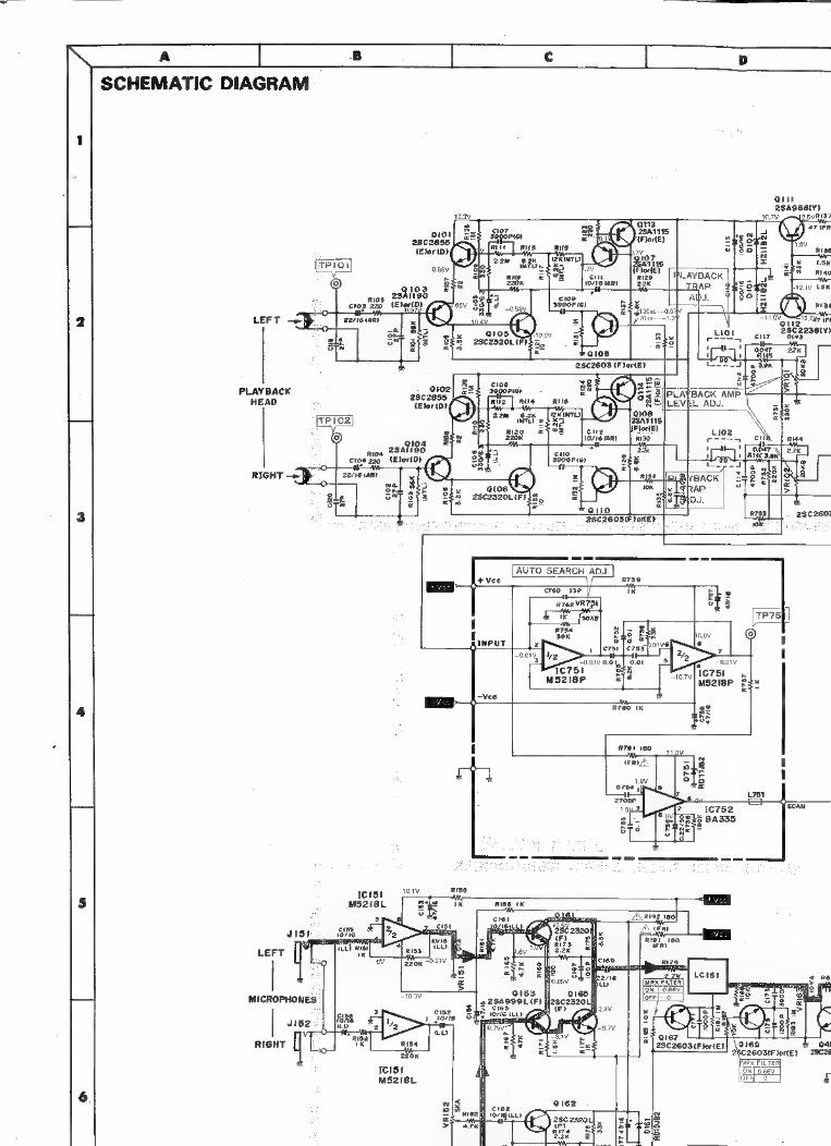
SCHEMATIC DIAGRAM
PLAYBACK HEAD
om 2saseety)
LAYBACK TRAP
q 06)
cus
2109
Sor i ae
Riss 10k
ica
RIGHT —= c1gs'220
22/6.AR)
25¢2603 (Forte
102] 2802855 {E}0r (0)
Rios 2sati83 (rort0)
2802603
Te7s! M5218P
ereersy ‘loo
Rr ie
Lammers mere iow ‘Bae
1s? 28C26031F orl)

1
8 A nisz AN ve
Es }
us e ! fe vouon bg ue = gear R553 Lch ie
IC50) —-HA12058.01
re nae a = “2 : 063 ¥ vosiewu [R5OF Sel 4
23C2603(E10KF) 4K 8
on esh x 188s A “1 at
Sw406('/2)
| tape
1 monitor = ea a nomron
cr a eee ss05tE of) weco [8 t
8 ' ;
! Fpsence 5 me eso g age [ - ae a 821 nore] (case
71 ie tp 7 eh ea 088/50
ome | B83 49| ©) ‘ iasie 1
$45) ol) al. ate See 1 Ss) ey Lesage 2] “Ts
*
‘ £201 ‘060 oe Reor ‘ “wl z irs E
1 | 3
“ourrer | os8 jase gei8 E23 ch | opaaiy] f fiw i i oe etiewn | a7
: oly | 27 2s es aa oa 3 "sey 6 Gv Bay eov
1C561—_Hat205801 gov av epv Cae ee ee if
ourhur EC INPUT eet finds nd - jovietu) [A36t Bie =
am “is fee wie
reio A rf y em poLay NR on/ore
--—_—— - -. moncro ‘oureur seis 624 Re ae parte. mis
1562 HAI205801
ee are
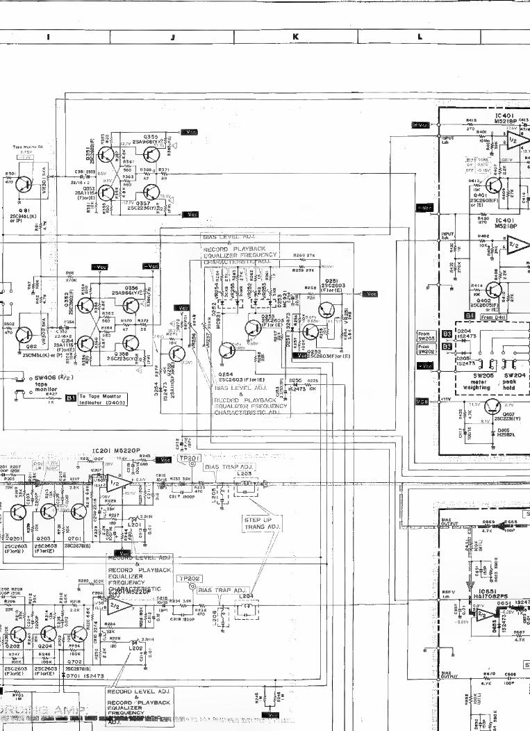
R301 18 “470 3
TEV 9357 sat asces6iige
280945L(K) ore) “ane
TSS CE
™
Racer
nave
22n6a2 asaitis
— (F)or(E} 2SCOHBLIK) oP)
| 3) 6 swaos (22) tape monitor
{ a Stare [EqI|T® Te0e Honor indicator (0409)
358 2 asce2a6inigo.
D254 neve fe 1s2873 2SAu84
y T RECORD PLAYBACK | RR FREQUENCY | reeo27e
Rat are 925) nese 282603,
Pore)
Es
252 SC26O3IF or (E)
‘| B5e2eosirrere) —_g| 0258 sve [ BiAS LEVEL. ADS. 38, 182473 10K
& 58 | RECORD PLAYBACK “| | EQUALIZER FREQUENCY
HADACTEDICTIC ADL
Ic4o1 MS218P C13
arr|coney 8
1201 MS220P
201 R207 Oop TOK “ aoe
wane C208 FEI lescesos Fiore)
‘asc2603 (Forte)
' x
| eSstbur) ef |e = ee - te
88% Ic401 ‘M5218P
neu aoe
q ies ! 1 es 5
' 1 Waves te
From [sw203| From [sw2o2
EB jigears
10208 is2a73
Vo204
47) 1 _SW205 sW204 |
meter peak 1 weighting — hold
RECORD PLAYBACK | EQUALIZER
£222,008 | FREQUENCY Te cepiMsezee sa 00P 120% ‘i ‘Reoe
[P2802 }
‘te
e204 e
et ie =] agcesos[ascasos | [ascze76) 7 eres? [RAG | Foren ieoa7s _/ |
zt i RECORD LEVEL ADJ | al oe & i He RECORD, “PLAYBACK He api. |avatwer EMI | eaeduency
1 i ‘ ‘ Ek
REF Ic651 Loch, HAI7082PS [ ale Noo PSohulag®
Be - 1 1
Rese
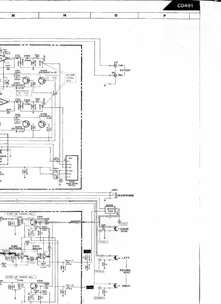
ys Leh 1
ouTPUT _| 94, J
Reh
= fusing } PSH Sooe sh IP sek Soey |e
22007 28¢26031F)) ‘or (E
asst 2sc3246ii Ti eget
csi RECORD
HEAD STEP UP Twa
es “Le6s2 ese
ert AN = cece (60g 75
coer
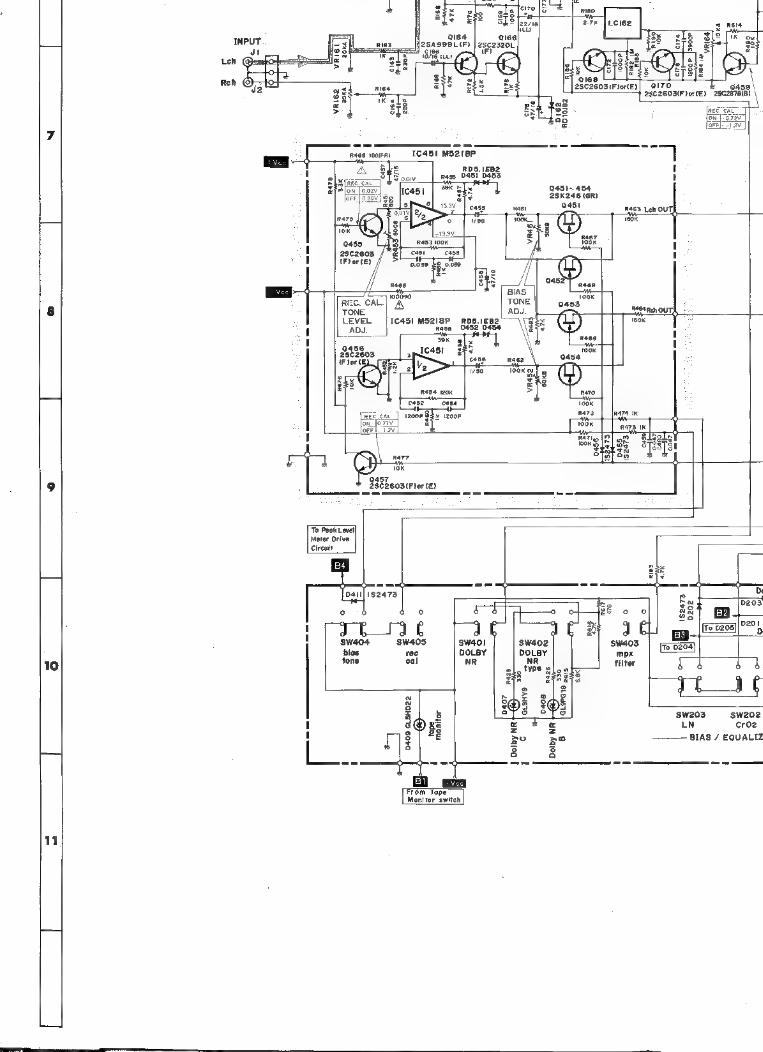
10
abl
1C451 M5216P on [= 0451~ 454 28K246 (GR)
9451 aes Leh OUT]
2SC2603(F JorlE) | 2802878(0) 9459 | \ a
1 28C2603 1 rere
RIC. CAL.” TONE 4 _| [EVEL | 1casi msziep gps.igge on | age S168 Saba i “ADS.
1 ' Bbo3 @erg
2 L case can
“alte Ts altos rere | fegre m : 100K | ears ie
Pad ' tog lee agrr pps i 18K
9487 28€2603(F)or (E)
To Pook Level Meter Drive Circult
°
py esie 1 ! swao4 SW405
bias 0c tone cal
t
rom Taj Monitor switch
7 pe a :
eS oo és? Ea. [Fa 0208] d [3
sees mpx ‘ filter i 4
5 2 sw203 Sw202
LN croz BIAS / EQUALIZ
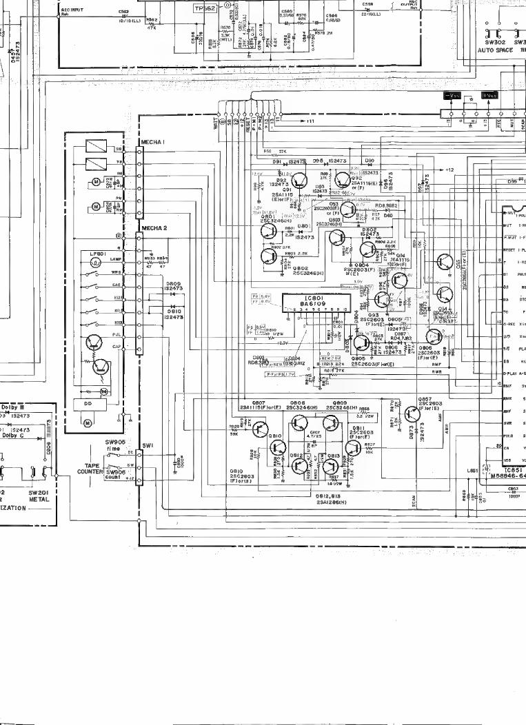
i cose j ouTkur [pgcneer ey AF a eae ies “22 2 5 zation Teen ae 3 i 3 ; ak eta] § 1
]] 2 a7a| 8 Sxzsye W302 SW3 Q 283815 AUTO SPACE RI ix \ e2| I a3
i '
= ne ase 2 e m
Bek isdars ds agree $88 ste ah efs 091 or 2 agate i afte
ert uy tov 2; ' TBI sunt few
S5c3246 oor
id . reser 1 als shen
i th. B os { B09 825% a a ae
1 Jaq si L os ax sty EST 8, tbe 3
=F Pasa !ounee xi [i [esleoe we aw le x0
H 0806 ws Pu 2sceeos 828 ray 0805 Prone hme
ofinare atx 25¢260316 ror) awe etre nue ua as es lowe 5
7 Inve s ee ‘807 808 9809 x 3862603 Dolby B 2SAINISIF)oME) 25C3246(N) _25CS246(H) pase 2 ‘Forte ex pai isa73 ! > satew) | oe 3 i isea7a || 288b603 Sas 5 Dolby ¢ 2 son ato! forte) ays russ
H swi — bs hey v imo a 5: mae 4 1g Es fos
< | Teast f I OUTER owace t 28c2s03 "M58846- 6¢
| $12 (Forte) bos | 1 a 2 sw2oi ! 812,813, | H , METAL 2SAl286(H) Fy " IZATION a
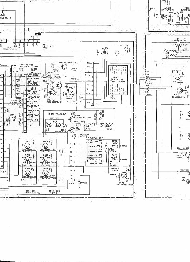
1 1s ea l ft v301 REC MUTE
{SCAN wr Mur CPR, PUAGE|O2
63 eH
DS136E
(0907 _28c2603(FIor(E) faa} pase TURI22 Dess~as5 TLGI2I 9B 1s2473, e273 (ase i pus 2 emo 10
rappeesrage™" 2 bad a3
5 stantrstor o RO
ry 2 com z cf a vs
vs
Leo couon Je stwerare
‘Tease, 3Ly Menus #8| |swios Rec Aaa Iswiog STOP. fo} |swio3F.F wo! {o> Iswio2 PLAY
Iswiol REW ace Matic dl tiv
2SC26031F Io ED
voo3 8/0 15 nEseT 16
38s F| a
count
IcsoI Tc4001BP D804 1s2473
a
E Ic901
902,903, is2473 ‘swaoave) oFF | 0867. AUTO: = ° sa 8280 mill Pr | os ‘swe a 51 S0e os ~ ij
3 pane 2 (38 3 loz sweoateorr © | PSSar3
AUTO bese . foes ro73] ||, ur Swo02 Fi make
SW8O3 REC 10870. os fark sen Ise is2473 a 0853 Sis a memory Ss
i rats eat frac [Raez scan
3 fem son : ot Pr
LPeoe owe @ 2eboamre) esi~s56 2SANISIF)orlE)
e59~e66 182473 Eee
REF Ices2 1C65: Boh HAI7OB2PS Hal7062
T Des2. 1s2a73
fasc2603 |FrertE) 910]
2sc2603 FI or(E)
es «rove
056, 182473
air 2SAI115 (EortF)
ce
ord 38k 087
1824
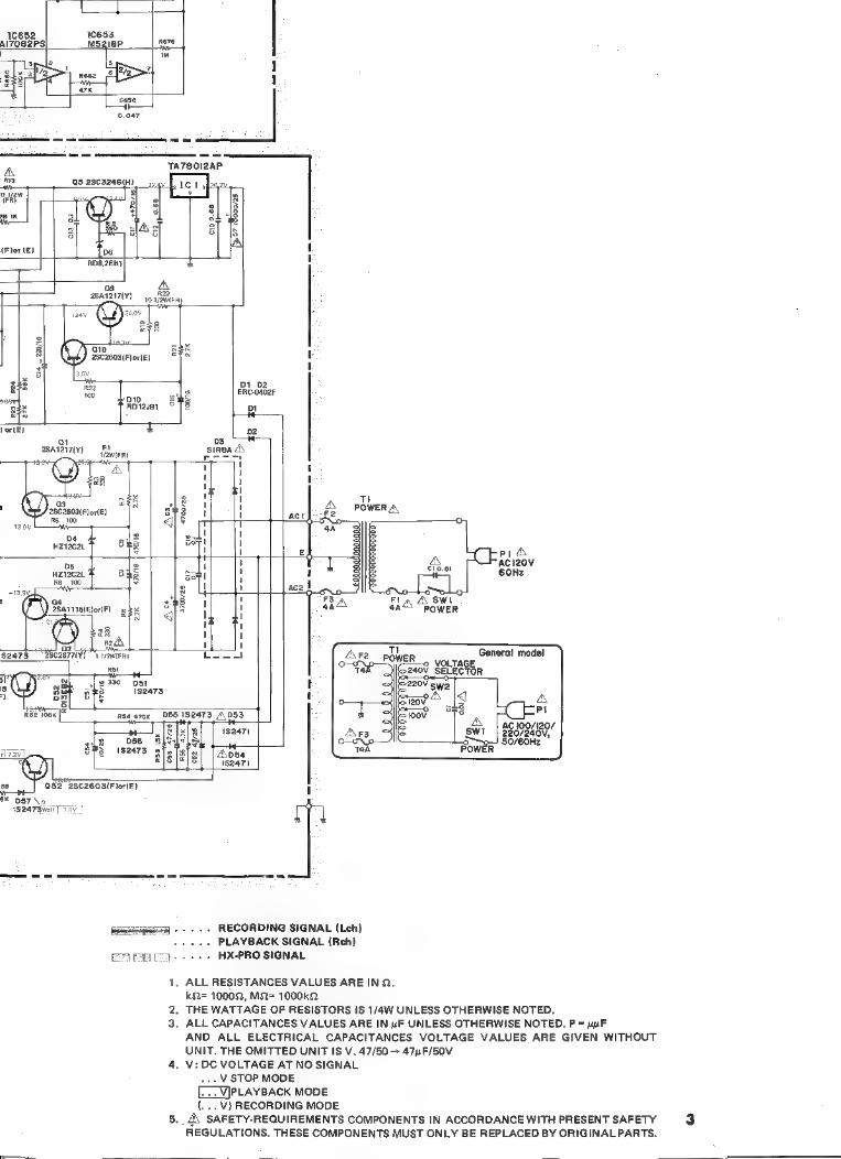
ic652 Al7082PS) MS2i8P ere
case ‘ 0.047
‘TATSOIZAP
8.2687
taweny or
asararay) At
a9v
aa 28A1115(E}or()
2
ro $2473 2877(¥) 1 AWE)
wat [22° 51 ry aes 182473 Bub ere
ceotond 4, 470K mA) B 1s2a71
a EB Ie a 3 Avsa 4 mi 1s247
:6 083 Bscz603iFieri= Be OST \o Sear bovis 7a
1, ALL RESISTANCES VALUES ARE INQ. k= 10002, M= 1000k2
. RECORDING SIGNAL (Lch) PLAYBACK SIGNAL (Reh)
. HX-PRO SIGNAL
AC 100/120/ 220/240V, 50/60Hz
2, THE WATTAGE OF RESISTORS IS 1/4W UNLESS OTHERWISE NOTED. 3, ALL CAPACITANCES VALUES ARE IN uF UNLESS OTHERWISE NOTED. P = uu F
AND ALL ELECTRICAL CAPACITANCES VOLTAGE VALUES ARE GIVEN WITHOUT UNIT, THE OMITTED UNIT IS V. 47/50 > 474F/50V
4, V:DC VOLTAGE AT NO SIGNAL V STOP MODE
_.: VIPLAYBACK MODE (... V} RECORDING MODE
5._4\ SAFETY-REQUIREMENTS COMPONENTS IN ACCORDANCE WITH PRESENT SAFETY REGULATIONS. THESE COMPONENTS MUST ONLY BE REPLACED BY ORIGINAL PARTS.

General model To PCB-2
BIAS LEVEL ADJ.
& RECORD / PLAYBACK OUTPUT INPUT MICROPHONES EQUALIZER FREQUENCY Lert J3 J! LEFT LEFT JISI CHARACTERISTIC ADJ. J2 RIGHT — RIGHT JI52
PCB-I RIGHT J@ J2
z VOLTAGE 5 vR2sI
i SELECTOR PCB-2 BIAS EINE PI TRIM AC 100/120 ‘ one 7220/240v s 50/60H2 ak “@7 G odbe
“<7 (sa
Doe 4 = PI
AC 120, ge ote
oon s@- pr 4 “re =a va03
SO Se ] als 6 |
ol <| fem fae : jot! S]
13 KS | = ig st TR 7 ‘ 8 | lelownr
= -
= a TP20:
TP20]
ia aio
8 Bh G EB
2) a 4 [ !
roe 28 eo gE
i) fe | If) a APB wks
i : — Wt ES H —— (St PEAKING a = Cp Goo Xe,
Qe ; 2 | Let COIL, ADS. |} 2 Safe 8
: Het = wth: 2 jet RECORD / PLAYBACK | Hees ——- i | [ooo
i Bs ek EQUALIZER FREQUENCY |—|—— —_ & Q so eed lel war CHARACTERISTIC ADJ. || Se Be Se
a3 88+ pats eo at mw pacers as
3 >. e =
D.D.MOTOR , CAPSTAN ew ett 3 :
(- POWER F " cA 2 te |
ae tt o——ee: a2
s00-GD—> aki Dc MOTOR, ASSIST
LP8oi T J
CASSETTE face |
ILLUMINATOR ya! :
“EVAill [ aes 5) — ie
] [74Pe P| ADJ.
rT MIS-ERASE PROTECT
ROTATION SENSOR P.C. BOARD SWITCH cease HEAD DOLBY B-C NR BIAS/ EQUALIZATION —TIMER— mpx ' Peak meter
lie NR type __filter METAL Cro2_LN play off rec weighting + — TAPE COUNTER — Sw401 SW402 SW403 W203 BO2 SW803 reset time count
SW904 SW905 S
een CASSETTE |
PACK DETECT SWITCH 3
OC MOTOR, REEL = WE i SW90I Sws02 sw903 SW404 sw405 memory = —AUTO— tape monitor | > bias tone reccal |
rewind replay : i Urepeat
PCB-5 Pattern Side
PcB-II Erg Rezo ou Be
snectaegely sb 5
dd te 5 apes f ILLUMINATION
PCB-5 poh re oct PCB-9 ae Parts Side dd baad ‘fe }
war eT aH VARIED Var 1
Lat = toh S|! [a a ice Z. oj : 101 6 RECORD LEVEL ADJ.
ney ela reve pales RecoRD PAUSE sw302 SW301 ie 0406 PEAK LEVEL METER - PCB-10] = Dolbynr - RIGHT LEFT MIC LEVEL OUTPUT AUTO REC rec cal : MASTER J351
AUTO SEARCH AUTO SEARCH —REC LEVEL — LEVEL SPACE MUTE FADER HEADPHONES
PIN CONNECTION DIAGRAM OF TRANSSISTORS, DIODES AND ICS.
RD4,7JB2 HA17082PS TD62503P ; 2 Collector Collector oe WIRE cOLor ABBREVIATIONS
: Bose Emitter Emitter Base ORG : Orange
SDP : BLU : Blue Li € WHT : White
i GRN_ : Green
ce tee 2SK246 ISK381
wale = TRANSISTOR TRANSISTOR PIR pinks
Ze Pad go ES | Ze ZA LS 4 8 Ov S
3ecaase i ERGOIO2F SBE Y ; lobo | ~

iN ad | ¢ D
WIRING DIAGRAM
1
General model = To PCB-2—
2
PI tJ AC 100/120
/220/240V
50/60Hz
3 PI AC 120V,
e = 60Hz
am RZ
ee
Swi 4 POWER
8 ee ee
° a

PCB-2
Sarre aol
5 lll I
llia
fay ro
secye—cp-0 "90° -GD-*
ae be abeg: | E
2| te
g aaased
=.
ear
oY
3[eaeese ste
ae
TSS SC) os
oe ro 56
=e
Be
2
é: ae
|
: Qa
} i
go-@be Be
.
z
iy
- sp)
si a3
a9
jee 4
28 :
‘
: :
te Pa
:
pitils
Cao
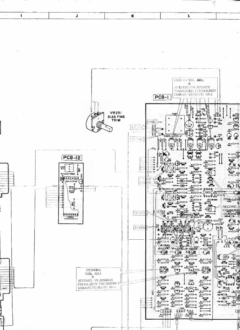
i vR251 BIAS FINE
| TRIM
: _paethigernedamenn 7
| PCB-i2
| { |
7 | i
| :
{
Tween i
i
| oe eee
fs -| H| a “oy "Grom {Ohl
RECORD. | ie
EQUALIZER FRE + ais
rae | CHARA
i
i
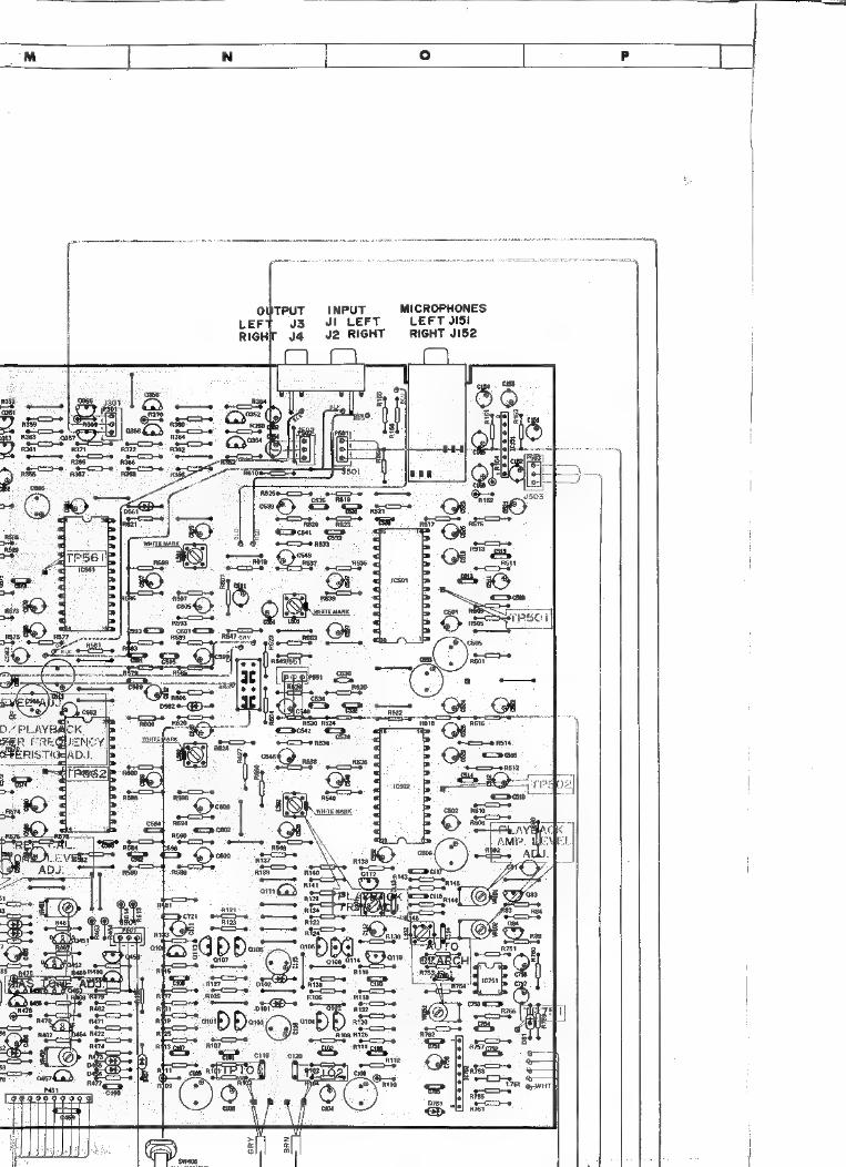
INPUT Jt LEFT J2 RIGHT
MICROPHONES LEFT Jisi RIGHT JIS2
as) eag9593eoq
BRN

a @ vee °} Os eo @
Fe ons pvee | SY ooo ons
[= Yeu we LP8Oi EORIPURETY |
CASSETTE alelehd - g| ILLUMINATOR aaa |
rvrl @ @
7
MIS-ERASE -——-—— PROTECT ROTATION SENSOR P.C. BOARD SWITCH
Jory on |
CASSETTE 8 PACK
DETECT SWITCH
PCB-5 Pattern Side
9
PCB-5 aa L hr ne oe ct ~ ot - - Parts Side =
ee Sh Sia Rae ct
10 SwIol REW
AUTO SEAR
PIN CONNECTION DIAGRAM OF TRANSSISTORS, DIODES AND ICS.
W RD4,7JB2 RDS.1EB2 RDS 6/82
2SAS99L on | 28A1115
2SA1190 2SC945L. 28023201 y=)
2855 eZ DS135E ERCO402F
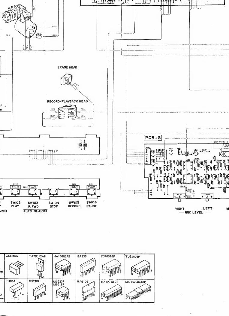
ERASE HEAD
" SS .
1 swio2 SWwio3. SWio4 swios swioé U uy
3 PLAY iP RECORD PAUSE oa Pail ee RIGHT LEFT m (RCH AUTO SEARCH REC LEVEL
HA17082PS =| BA335 TD62503P
HA12058-01

= eee Bosa|x lax 2s
eee ele glories = | a dl | im | So emery | pod ' | poLey B-c NR
| | i | ra \ a my Sehgntie j _sw01 sh swaoz SW403
| | Pat swa04 sw90s 5) M208, i Sears on i (al es
' | i oo] fo] fe ele ey ea. | fe a4 36) (ae) le) JE) (26) 96) ~ | ; é a als 4 i i 8 3 saleatend é
oe H | DEI E TIE
i i | i SW90! Swe02 sw903 i } i memory = —AUTO— tape monitor
Cnse : rewind replay | “repeats
{
| i
j { |
i PCB-9 ||. ‘
aN LAS ae
$w302 sw3o1 REGO a ot rai | D406 PEAK LEVEL METER MIC LEVEL OUTPUT AUTO
LEVEL SPACE MUTE

BY B-C NR BIAS/ EQUALIZATION —TIMER— i mpx Peak; — meter
2 type __filter METAL cro2 LN play off hold | weighting 1 SW402 SW403_-SW20I Sw202 Sw203 “Swag! SWROZ ‘Swaos sW20. 5
“te SIMD SUITE a . | Soy 3 corn ug BE gy ; ie i i oy
e| [fe [ee esi fe sl [2 Sea & So [e eli¥(e =e) ews
E) ak aE oe JE) ~— GELS eae aE # ] —— WHT preg nee WHT O Js i 1
oon — @ a ee £ ba —— |e) IE |
t q sw404 sw405 i 741) tape monitor bias tone reccal : PCB-4 |
i ' | i J
|
ILLUMINATION
}
EVEL METER PCB-10] dobynr MASTER J35I FADER HEADPHONES
R ABBREVIATION: Collector Collector “RED Shes . . i i ORG : Orange Base Emitter Emitter Bose impel
WHT : White GRN : Green BLK : Black
ne sae : Purple TRANSISTOR PIK : Pink TRANSISTOR
lolol ~

‘@harman/kardon Service Bulletin
SERVICE BULLETIN #4005 - DECEMBER, 1984
TO: ALL HARMAN KARDON WARRANTY STATIONS
MODEL: CD391/CD491 STEREO CASSETTE DECK
SUBJECT: POP SOUND RECORDED ON TAPE
In the event you receive a CD391 or CD491 Cassette Deck with the complaint "unit records pop or bleep on tape when placed in record pause mode" we recommend you solder on the micro processor
PC Board a signal diode between IC 801 and IC 852.
The anode of this diode is connected to PIN 6 of IC 801 and the cathode of this diode is connected to PIN 14 of IC 852.
The purpose of this diode is to prevent the transport from rewinding the tape momentarily at the moment the pause button is
r ) depressed.
Due to this momentary rewind of the tape while the bias oscillator is on, the bias signal will be recorded on the tape at high tape speed. When the tape is played back this high frequency signal
becomes audible.
The modification indicated above will prevent this momentary rewind.
Harman Kardon Incorporated, 240 Crossways Park West, Woodbury, New York 11797 (516) 496-3400 TELEX: 22 99 11 HARMN UR