MANITOBA GAS NOTICES...Revised September 2000 Manitoba Gas Notices The purpose of the Manitoba Gas...
90
M M A A N N I I T T O O B B A A G G A A S S N N O O T T I I C C E E S S Second Edition September 2000 Published by: Mechanical and Engineering 500 – 401 York Avenue Winnipeg, Manitoba R3C 0P8 http://www.gov.mb.ca/labour/safety Client Services (204) 945-8114
Transcript of MANITOBA GAS NOTICES...Revised September 2000 Manitoba Gas Notices The purpose of the Manitoba Gas...

MMAANNIITTOOBBAAGGAASS NNOOTTIICCEESS
Second EditionSeptember 2000
Published by:Mechanical and Engineering500 – 401 York AvenueWinnipeg, ManitobaR3C 0P8http://www.gov.mb.ca/labour/safetyClient Services (204) 945-8114

Revised September 2000
Manitoba Gas Notices
The purpose of the Manitoba Gas Notices is to provide gas and oil fitters guidance onCSA B149 Gas Installation Code requirements as they apply in Manitoba, Manitobalegislative requirements as they pertain to gas and oil burning installations, andMechanical and Engineering Branch policy.
The Gas Notices were developed by the Manitoba Joint Committee to Review the CSAB149 Gas Installation Code, and its Gas Notice Review sub-committee.
The Manitoba Joint Committee to Review the CSA B149 Gas Installation Code iscomprised of representatives from the Mechanical and Engineering Branch, Centra Gas,educational facilities and industry.
Committee MembersJudith A. Fraser Mechanical and EngineeringTerry Rieger Mechanical and EngineeringLarrie Happy Mechanical and EngineeringDavid Warriner Mechanical and EngineeringVictor Pao Mechanical and EngineeringKen Wilson Centra GasMinke Stornel Centra GasJoe Yule Centra GasLeo Bonneville Centra GasKevin Leathwood Centra GasGlen Gatin Assiniboine Community CollegePerry Allan Red River CollegeGerry McCutcheon Red River CollegeGord Duncan Keystone Mechanical Contractors AssociationGrant Hein Heating Refrigeration Air Conditioning Contractors Manitoba
Chapter (HRAI)Wilf Sawatsky S.E. Mb Licenced Mechanical Contractors Assoc.Colin Kihn S.E. Mb Licenced Mechanical Contractors Assoc.Dave Eidick Gladstone Austin Natural GasBob Meek Manitoba Propane Committee of PGACDon Hoornaet Manitoba Propane Committee of PGACPaul Guillou Union Energy— Furnasman HeatingWayne Peters Angle PlumbingDarcy Shorrock Abco Supply and Service Limited
The Manitoba Joint Committee to Review the CSA B149 Gas Installation Code thanksJoe Yule of Centra Gas for his work on the drawings, and Gwen Anderson for her workcompiling the text.
Revisions: Portions of these notices that have been revised or amended since aprevious edition are marked with the triangle ‘delta’ symbol, as is the custom in theB149.First Edition— May 2000Second Edition— September 2000

September 2001 addendum to Sept 2000 Manitoba Gas Notices
Manitoba Gas NoticesAddenda Note
Revisions: Revisions or amendments made to a notices since a previous edition are markedwith the triangle ‘delta’ symbol, as is the custom in the B149.First Edition— May 2000Second Edition— September 2000First Addenda release September 2001
The Third Edition of the Manitoba Gas Notices will be released in 2005; revisions or amendmentsmade to the Notices September 2001 and release of the Third Edition will be made by the releaseof Addenda pages.
This page to be added to the September 2000 edition following the preface page titled"Manitoba Gas Notices"

Revised September 2000
Index
Gas Notice 1 Responsibilities of a gas fitter
Gas Notice 2 Approval Labels
Gas Notice 3 Initial start-up procedure for high input equipment(equipment exceeding 400,000BTUH)
Gas Notice 4(A) Preventing excessive cold air when providing airsupply to commercial and industrial installations
• Figure 4 (A) Acceptable method for the installation of a Method 1 commercial combustion air supply duct with a
ceiling that is above grade level• Figure 4 (A ) Acceptable method for the installation of a
Method 2 commercial combustion air supply duct with a ceiling that isat or near grade level
Gas Notice 4 (B) Preventing excessive cold air when providing air supply toresidential installations
• Figure 4 (B) Acceptable method for the installation ofresidential air supply
Gas Notice 5 (A) Metal liners in masonry chimneys
Gas Notice 5 (B) Metal liners in masonry chimney
Gas Notice 6 Procedure for propane installations
Gas Notice 7 Construction Heaters
Gas Notice 8 (A) Access to roof-top equipment• Figure 8 (A) Acceptable method for the installation of fixed
ladders providing access to rooftop units over 13 feet andbelow 26 feet in height
Gas Notice 8 (B) Access to roof-top equipment (Fall protection on a slopedroof)
Gas Notice 9 (A) Acceptable method for installation of roof-top piping on asloped roof
• Figure 9 (A) Acceptable method for installation of roof-toppiping on a sloped roof
Gas Notice 9 (B) Acceptable methods of pipe support on a flat roof• Figure 9 (B) Pipe supports on flat rooftop installations
Revised September 2000
IndexContinued
Gas Notice 9 (C) Regulator stations on rooftops• Figure 9 (C) Acceptable methods of regulator stations installed Method 1 on rooftops• Figure 9 (C) Acceptable methods of regulator stations installed
Method 2 on rooftops
Gas Notice 9 (D) Semi-rigid tubing on roof tops• Figure 9 (D) Acceptable methods of installation for copper and
corrugated stainless steel tubing on rooftops
Gas Notice 10 Sizing natural gas, propane and butane orifices
Gas Notice 11 (A) Copper and corrugated stainless steel tubing for residentialuse
Gas Notice 11 (B) Copper and corrugated stainless steel tubing for applianceconnections
Gas Notice 11 (C) Acceptable method of installing semi-rigid tubing usinghorizontal slack with no swing joints
• Figure 11 (C) Acceptable method of installing semi-rigid tubingusing horizontal slack with no swing joints
Gas Notice 12 Propane storage tanks on a construction site
Gas Notice 13 (A) Sizing a manifold downstream of a gas meter• Figure 13 (A) Determining manifold size downstream of gas
meter
Gas Notice 13 (B) Sizing pipe for pipe diameters 4 inches and over
Gas Notice 13 (C) Sizing pipe for 15 psi supply pressure
Gas Notice 14 Flexible connectors
Gas Notice 15 (A) Installation of buried steel pipe to supply residentialoutbuildings
• Figure 15 (A) Acceptable method for installation of steel pipe(underground) supplying residential outbuildings

Revised September 2000
IndexContinued
Gas Notice 15 (B) Installation of buried copper tubing to supply residentialoutbuildings
• Figure 15 (B) Acceptable method for installation of coppertubing (underground) supplying residential outbuildings
Gas Notice 15 (C) Installation of buried plastic pipe to supply residentialoutbuildings
• Figure 15 (C) Acceptable method for installation of plastic pipe(underground) supplying residential outbuildings
Gas Notice 16 Clarification of appliance vent termination• Figure 16 Clarification of Section 7.14.8 (d) & (e) of the
current B149 gas code
Gas Notice 17 Unvented agricultural heaters
Gas Notice 18 Piping to commercial cooking equipment• Figure 18 Acceptable location of shut-off valves installed
within a commercial kitchen
Gas Notice 19 Street Elbow Fittings
Gas Notice 20 Piped connections to mobile homes• Figure 20 Acceptable method for the installation of a trailer
hook-up to a utility meter set
Gas Notice 21 Installing polyethylene pipe by ploughing or pushing
Gas Notice 22 Unvented residential space heaters and unvented decorativeappliances
Gas Notice 23 Venting• Figure 23 (A) Access to the Base T• Figure 23 (B) Bracing for outdoor terminations• Figure 23 (C) Replacement appliance connected into an existing
‘B’ vent• Figure 23 (D) Replacement appliance connected into an
Existing approved liner system
Gas Notice 24 Inspection of heat exchanger failures
Gas Notice 25 Clearances to a natural gas utility regulator

Revised September 2000
• Figure 25 Clearances to a natural gas utility regulator
Questions & Answers

Revised September 2000
Gas Notice 1Responsibilities of a gas fitter
Rationale: To clarify gas and oil fitters’ obligation under the Manitoba Gas and OilBurner Act and Regulation to provide inspecting authorities all requireddocumentation pertaining to gas and oil equipment installations, and to obtaininspection and approval as necessary.
Permits must be obtained prior to commencement of all alterations, additions orinstallations of gas piping or equipment. To comply with requirements of theRegulation with regard to permits the following shall be carried out:
1. Fees must be submitted with each application2. Drawings in triplicate must be submitted with all applications where the total
input of all units to be connected exceeds 400,000 BTU per hour
Drawings must detail:(A) The length and size of gas piping and gas pressure(B) Any piping which will be concealed(C) In the case of conversion burners
(1) Details of valve train and controls(2) Location and size of supply air provisions(3) Size, height and type of chimney breeching(4) Draft hood or I.D. fan, etc.
It is essential that the application for permit be properly completed with particularreference to the legal address and correct name of the installation premises; theapproximate date of completion; and the signature of the licensed fitter who ismaking the installation, alteration or addition.
Permit applications will expire if the inspection and turn-on is not completedwithin 90 days from the date of issue. Extensions may be granted by the ChiefInspector.
The Mechanical and Engineering Branch must be notified if there is a substitutionof equipment specified on the original permit.
Under the Gas and Oil Burner Act and Regulation, a gas fitter must:
1. Make application for a permit prior to commencing installation2. Ensure that all appliances and equipment are approved3. Pressure-test piping and ensure that there are no leaks4. Purge all gas lines after gas turn-on5. Start up all equipment installed by the fitter6. Perform a heat rise test in compliance with the manufacturers’ specifications7. Check operation of all controls

Revised September 2000
Gas Notice 1Responsibilities of a gas fitter
Continued
Under the Gas and Oil Burner Act and Regulation, a gas fitter must:(continued)
8. Make application for a permit prior to commencing installation9. Ensure that all appliances and equipment are approved10. Pressure-test piping and ensure that there are no leaks11. Purge all gas lines after gas turn-on12. Start up all equipment installed by the fitter13. Perform a heat rise test in compliance with the manufacturers’ specifications14. Check operation of all controls15. On conversion burners: carry out a combustion efficiency test and record the
results.16. Identify the installation with the fitter’s current tag and ensure the removal of
any pre-existing tags17. Instruct the owner in the use, operation and maintenance of the equipment
Fitters’ responsibility to notify the Mechanical and Engineering Branch1. General gas-fired Installations
Prior to activation of any installation where total gas supplied exceeds400,000 BTU per hour, the fitter must contact a Mechanical and EngineeringBranch Gas Inspector to arrange for a start-up inspection appointment.
2. Boilers or pressure equipmentPrior to activation of any boiler or pressure equipment with a rating greaterthan 3 Boiler Horsepower in other than one- or two-family dwellings (3 BoilerHorsepower = 30 kilowatts = 126,000 BTU/H INPUT), the fitter must contact aMechanical and Engineering Boiler Inspector to arrange for a start-upinspection appointment.
Note: Only installers holding a valid Certificate of Authorization issued by theMechanical and Engineering Branch may apply for a gas permit to installboilers of this rating or higher.

Revised September 2000
Gas Notice 1Responsibilities of a gas fitter
Continued
A Certificate of Authorization is issued to an installer of pressure equipmentand/or piping who demonstrates an acceptable Quality Control Program.Although gas piping does not normally fall under the Certificate of Authorizationprogram, gas fitters installing pressure equipment must be qualified to theManitoba standard to do so, or must work under the authority of a properlyqualified contractor.Contact the Mechanical and Engineering Branch for more information on theCertificate of Authorization program and Quality Control.
Fitters’ responsibility to notify the UtilityPrior to any activation, the gas fitter must notify the gas utility or propanesupplier to request an inspection when:1. Replacing an appliance or making a new installation2. Making alterations to gas equipment or piping3. Installing additional equipment or piping
The only exception is where a gas-fired residential appliance is installed toreplace a similar appliance, the fitter may ignite the appliance provided that thefitter notifies the gas utility forthwith that the appliance is operating in a safemanner.Where an additional or replacement gas-fired commercial or industrialappliance is installed, the fitter must notify the Mechanical and EngineeringBranch and the gas utility or propane supplier and request an inspection prior toturn-on as described in the Inspection Requirements sections.
Before supplying gas, the gas utility or propane supplier will:1. Check that the installation conforms to the current CSA B149.1, B149.2 or
B149.3 and current Manitoba Gas Notices2. Check that the appliances are approved and labeled3. Check for leaks with a meter dial test or propane regulator test4. Check and record gas fitters tag on each applianceDiscrepancies found during these checks may cancel gas turn-on until they havebeen corrected. The Mechanical and Engineering Branch will be notified of thesediscrepancies.
Revised September 2000
Gas Notice 2Approval Labels
Rationale: To explain and illustrate the certification marks of Approval Agenciesrecognized in Manitoba.
The Manitoba Gas and Oil Burner Act requires that all gas and oil burningequipment and devices installed in Manitoba be approved.
The Manitoba Gas and Oil Burner Regulation states:"approved" means approved and listed or labeled under the inspection serviceof
(a) the Canadian Standards- Association (herein referred to as C.S.A.),(b) the Underwriters Laboratories of Canada Limited (herein referred to as
ULC),-or-(c) the Canadian Gas Association, or approved by the
minister;All certification agencies accredited by the Standards Council of Canada areapproved upon application to the Mechanical and Engineering Branch.
The ‘Blue Flame’ Certification Mark:In 1997, CSA International acquired the organization that included both theCanadian Gas Association and the American Gas Association. CSAInternational was given a time-limited licence to use the familiar CGA and AGAcertification seals, but will replace the existing marks with new designs thatincorporate the CSA monogram.
In Canada, the new CSA certification mark for petroleum burning equipmentmust be used by July 1, 2002. Until then, the industry and regulators maycontinue to see the familiar CGA seal.
The existing CGA ‘Blue Flame’ seal and the new ‘Blue Flame’ mark that willincorporate the CSA monogram will be applied to appliances and equipment todenote compliance with all applicable gas, electrical and/or mechanicalstandards in Canada. A CSA mark that is not incorporated into the ‘Blue Flame’design denotes compliance with electrical standards only.
Revised September 2000
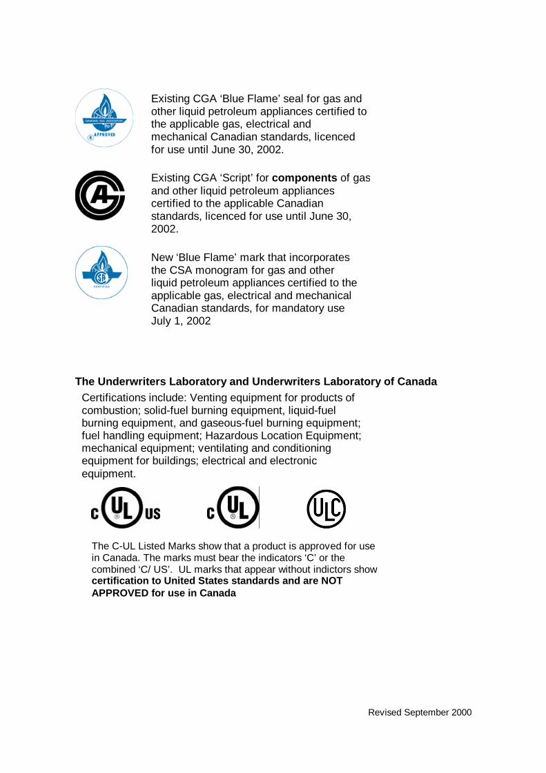
The Underwriters Laboratory and Underwriters Laboratory of CanadaCertifications include: Venting equipment for products ofcombustion; solid-fuel burning equipment, liquid-fuelburning equipment, and gaseous-fuel burning equipment;fuel handling equipment; Hazardous Location Equipment;mechanical equipment; ventilating and conditioningequipment for buildings; electrical and electronicequipment.
Existing CGA ‘Blue Flame’ seal for gas andother liquid petroleum appliances certified tothe applicable gas, electrical andmechanical Canadian standards, licencedfor use until June 30, 2002.
Existing CGA ‘Script’ for components of gasand other liquid petroleum appliancescertified to the applicable Canadianstandards, licenced for use until June 30,2002.
New ‘Blue Flame’ mark that incorporatesthe CSA monogram for gas and otherliquid petroleum appliances certified to theapplicable gas, electrical and mechanicalCanadian standards, for mandatory useJuly 1, 2002
The C-UL Listed Marks show that a product is approved for usein Canada. The marks must bear the indicators ‘C’ or thecombined ‘C/ US’. UL marks that appear without indictors showcertification to United States standards and are NOTAPPROVED for use in Canada

Revised September 2000
ETL Semko (a division of Intertek Testing Services North America Incorporated)certifications include:• Venting equipment for products of combustion; fuel-burning and handling
equipment manufactured to comply with CSA, ULC or CSA standardsincluding, where applicable, CE Code Part II requirements; electric andelectronic products; Hazardous Location Equipment.
Marks from both divisions must include the indicators ‘C’ or ‘C/US’ to showapproved certification in Canada. Marks that appear with no indicator, or with the‘US’ indicator alone are NOT APPROVED for use in Canada.
Omni-Test Laboratories Incorporated certifications include:• Venting equipment for products of combustion; fuel-burning and handling
equipment manufactured to comply with CSA, ULC or CSA standardsincluding, where applicable, CE Code Part II requirements.
The mark must appear with ‘C’ or ‘C/US’ indicators to approval for use inCanada. A mark that does not have an indicator or that has a ‘US’ indicatoralone is NOT APPROVED for use in Canada
Canadian Standards Association certifications include:• Electrical and electronic equipment; fuel burning and handling subassemblies,
components and accessories manufactured to comply with CSA , ULC, orCGA standards including where applicable CE Code Part II requirements;dispensing devices for flammable liquids manufactured to comply with CSAstandards and other recognized documents including the CE Code Part IIrequirements; containers for flammable liquids manufactured to comply withCSA standards and other recognized documents.
• Note that a fuel burning appliance must bear the ‘Blue Flame’ CGA orthe ‘Blue Flame’ CSA mark to show compliance with all gas andelectrical requirements in Canada.

Revised September 2000
The CSA mark may appear alone or with indicators. When the mark appearsalone, the product is approved for use in Canada only. Marks that appear withthe combined indicators ‘C/US’ or ‘NRTL/C’ show approval for use in bothCanada and the United States. Products bearing marks that have only theindicators ‘US’ or ‘NRTL’ have been tested to United States’ safety standardsonly, and are NOT APPROVED for use in Canada.
Mechanical and Engineering Branch Special Acceptance Label for FuelBurning EquipmentOccasionally, there is a requirement to use equipment that has not been certifiedby an agency accredited by the Standards Council of Canada and recognized inManitoba. For these cases, the manufacturer or installer may apply to theMechanical and Engineering Branch for a Special Acceptance for a GasAppliance.
A provincial Gas Inspector will inspect the equipment to determine its complianceto provincial codes and guidelines. The Gas Inspector may approve theequipment, order modifications to bring the equipment in line with provincialstandards or may prohibit the equipment from use.
The Mechanical and Engineering Branch Special Acceptance Gas Equipmentlabel:
Approval labels for Electrical products onlyThe Mechanical and Engineering Branch has a similar Special Acceptanceprogram for electrical equipment.

Revised September 2000
Other Electrical Marks:Met LaboratoriesCertifications include:• Electrical and electronic equipment; Hazardous Location Equipment.
The mark must appear with ‘C’ or ‘C/US’ indicators to approval for use inCanada. A mark that does not have an indicator or that has a ‘US’ indicatoralone is NOT APPROVED for use in Canada
TUV Rheinland of North America Incorporated Certifications include:• Information technology and office equipment including computers; electrical
testing, measuring and laboratory equipment; audio-visual equipment andaccessories.
The mark must appear with ‘C’ or ‘C/US’ indicators to approval for use inCanada. A mark that does not have an indicator or that has a ‘US’ indicatoralone is NOT APPROVED for use in Canada
Entela Incorporated
Certifications include:Electrical and electronic products.
The mark must appear with ‘C’ or ‘C/US’ indicators to approval for use in Canada.A mark that does not have an indicator or thathas a ‘US’ indicator alone is NOT APPROVEDfor use in Canada

Revised September 2000
Gas Notice 3Initial start-up procedure for high input equipment
(Input exceeding 400,000 BTUH)
Rationale: Recommended rules for commissioning high-input equipment.
This procedure has been developed to help ensure safe start-ups of high inputgas-fired equipment. Due to a large variation in the types of equipment andcontrols, some of the procedures as set out will not be applicable to certainburners. On some equipment other safety checks that may not be mentioned inthis procedure will be required.
The commercial and industrial gas fitter responsible for the installation must bepresent during the initial start-up. This person will be required to demonstratethat the installation meets all relevant codes, including the testing of piping, acheck of safety controls and electrical connections, safety interlocks and reliefvalve rating.
The fitter must ensure that all persons not directly involved in the start-up arecleared from the room in which the equipment is located, before start-up isattempted.
The fitter must ensure that any boiler with a rating greater than 3 BoilerHorsepower (3 Boiler Horsepower = 30 Kilowatts =126,000 BTU/H INPUT) is notactivated without prior notification and approval of the Mechanical andEngineering Branch in other than one (1) or two (2) family dwellings.
A dry-run shall be carried out with all manual valves closed to determine that allcontrols are in a safe operating condition before gas is supplied to the pilot ormain burner. It is suggested that the dry run checks will take a minimum of fourcontrol cycles to perform and can be carried out as follows:
First Cycle1. Check and determine the movement or position of the air dampers during the
pre-purge to ensure the air flow is not less than 60% of that required for theminimum input to the unit during this period.
2. Check volume of pre-purge air to determine its conformance with codestandard (at least four air changes to the combustion chamber and fluepassages)
3. At the end of the pre-purge cycle, check modulating gas valve and the airdamper to determine that they have returned to the low fire position.
Second CycleDuring pre-purge, simulate failure of the air flow or forced fan operation andensure that ignition spark does not occur. Failure may be simulated by failing a

Revised September 2000
motor, closing the damper, removing the belt, removing tubing connection fromair proving device, or other acceptable means.
Third CycleConnect a meter for measurement of scanner or detector signal. Check thisreading during the ignition period to ensure it reads zero. If there is a reading,the scanner or detector may be sensing a false signal due to spark, etc.
Note: the meter must be connected according to the applicablespecifications for the type and make of controls.
Fourth CycleSubject the scanner or detector to a simulated flame and check that:1. The pilot is proved2. The main gas valve opens3. The pilot is interrupted (ignition spark ceases)4. The trial for main flame is proven (the time between the opening of the main
gas valve and the interruption of the spark)5. The loss-of-flame signal is proven when the simulated flame is removed and
the main gas valve closes6. The manual reset valve, when used in conjunction with a firing valve that
incorporates an end-switch interlock, cannot be opened with the firing valve inan open position (carried out by subjecting scanner or detector to a simulatedflame)
The above procedure must be carried out separately for each burner on a multi-burner unit.
Start-up of burner or burners1. Purging gas piping(A) Do not open firing valve. This valve must remain closed until piping is
purged of air.
(B) Determine a safe location and method of dispersal of purged gas.
(C) The purge connection should be made between the manual shut-off valveon the drop and the pilot connection or main input valve.
(D) The purge connection must be large enough to ensure an adequate purgevelocity to evacuate air.
(E) The above conditions having been fulfilled, the piping can be purged. Toensure all air is evacuated, purging must continue until gas is detected atpurging tube by means of flaring or other positive method (not in thecombustion chamber of the unit)
Revised September 2000
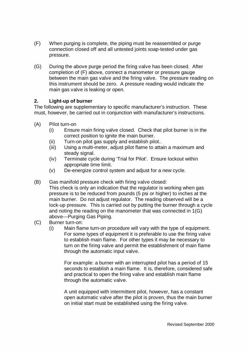
(F) When purging is complete, the piping must be reassembled or purgeconnection closed off and all untested joints soap-tested under gaspressure.
(G) During the above purge period the firing valve has been closed. Aftercompletion of (F) above, connect a manometer or pressure gaugebetween the main gas valve and the firing valve. The pressure reading onthis instrument should be zero. A pressure reading would indicate themain gas valve is leaking or open.
2. Light-up of burnerThe following are supplementary to specific manufacturer’s instruction. Thesemust, however, be carried out in conjunction with manufacturer’s instructions.
(A) Pilot turn-on(i) Ensure main firing valve closed. Check that pilot burner is in the
correct position to ignite the main burner.(ii) Turn-on pilot gas supply and establish pilot..(iii) Using a multi-meter, adjust pilot flame to attain a maximum and
steady signal.(iv) Terminate cycle during ‘Trial for Pilot’. Ensure lockout within
appropriate time limit.(v) De-energize control system and adjust for a new cycle.
(B) Gas manifold pressure check with firing valve closed:This check is only an indication that the regulator is working when gaspressure is to be reduced from pounds (5 psi or higher) to inches at themain burner. Do not adjust regulator. The reading observed will be alock-up pressure. This is carried out by putting the burner through a cycleand noting the reading on the manometer that was connected in 1(G)above— Purging Gas Piping.
(C) Burner turn-on:(i) Main flame turn-on procedure will vary with the type of equipment.
For some types of equipment it is preferable to use the firing valveto establish main flame. For other types it may be necessary toturn on the firing valve and permit the establishment of main flamethrough the automatic input valve.
For example: a burner with an interrupted pilot has a period of 15seconds to establish a main flame. It is, therefore, considered safeand practical to open the firing valve and establish main flamethrough the automatic valve.
A unit equipped with intermittent pilot, however, has a constantopen automatic valve after the pilot is proven, thus the main burneron initial start must be established using the firing valve.
Revised September 2000
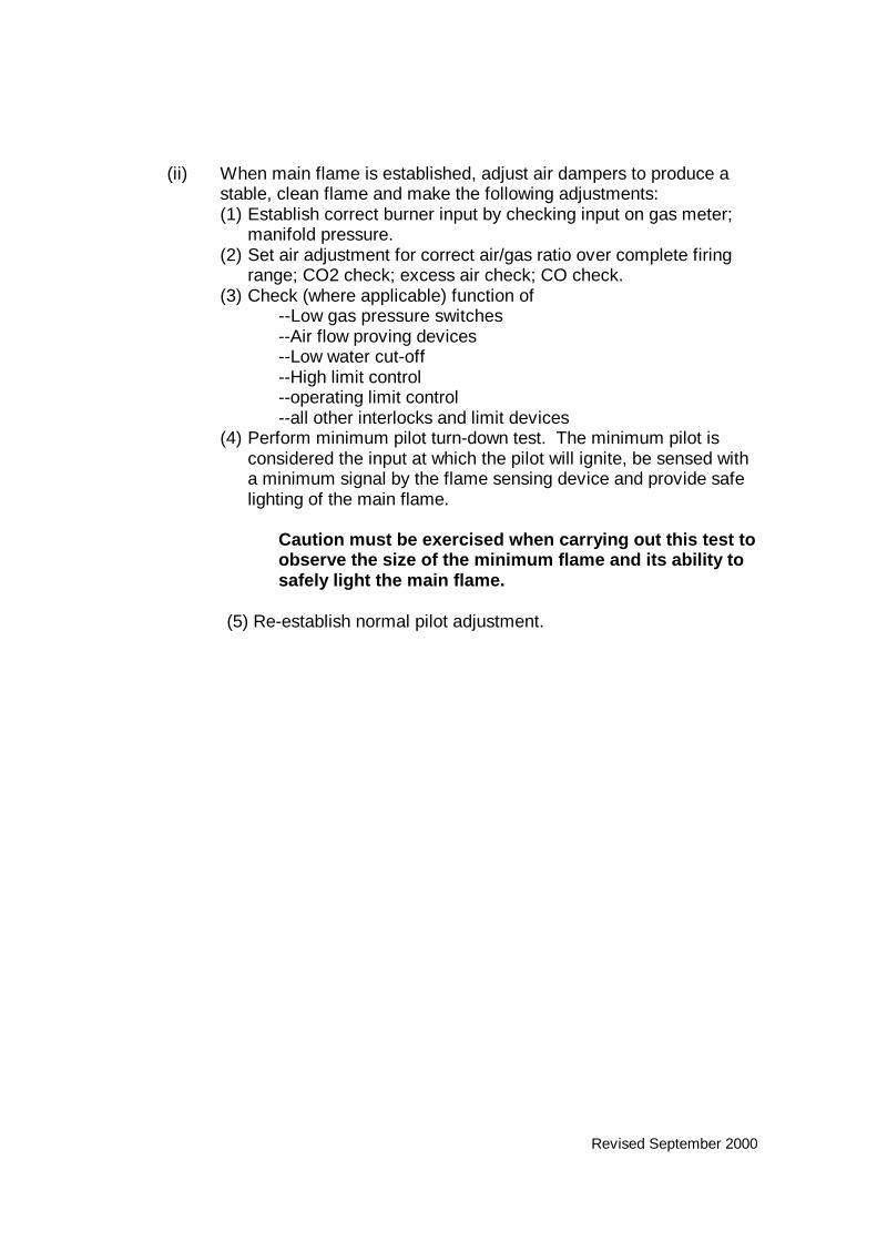
(ii) When main flame is established, adjust air dampers to produce astable, clean flame and make the following adjustments:(1) Establish correct burner input by checking input on gas meter;
manifold pressure.(2) Set air adjustment for correct air/gas ratio over complete firing
range; CO2 check; excess air check; CO check.(3) Check (where applicable) function of
--Low gas pressure switches--Air flow proving devices--Low water cut-off--High limit control--operating limit control--all other interlocks and limit devices
(4) Perform minimum pilot turn-down test. The minimum pilot isconsidered the input at which the pilot will ignite, be sensed witha minimum signal by the flame sensing device and provide safelighting of the main flame.
Caution must be exercised when carrying out this test toobserve the size of the minimum flame and its ability tosafely light the main flame.
(5) Re-establish normal pilot adjustment.

Revised September 2000
Gas Notice 4 (A)Preventing excessive cold air when providing air supply to commercial and
industrial installations
Rationale: To illustrate variations to the CSA B-149.1 air supply requirementsacceptable to Manitoba inspecting authorities so that fitters in Manitoba’s coldclimate can design installations that provide free flow of air without deliveringexcessive cold air.
Methods of providing air supply to gas-fired equipment shall comply with thecurrent CSA B-149.1. To prevent excessive cold air entering rooms wherecommercial/industrial gas-fired equipment is installed, the air supply inlet may beducted in accordance with Figure 4 (A) Method 1 or Figure 4 (A) Method 2, or bya method approved by the inspecting authority.
Refer to Section 7.6 of the current CSA B-149.1.

Figure 4 (A) Method 1
“A” The duct termination shall in no case terminatecloser than 12 inches (30 cm) from the ceiling.
“B” & “C” The duct shall be formed in the shape of an ‘S’with the outlet directed upward towards theceiling. The length of the portion turned upwardinside the building and also the length of theportion turned downward outside shall be equal toat least the depth of the duct.
“D” An air supply inlet opening from the outdoors shallbe located not less than 1 foot (30 cm) above theoutside grade level. (current CSA B149.1 Section7.3.6)
“E” Ventilation air shall be installed as close to theceiling and as far from the combustion air supplyduct as is practicable.
Air supply ducts shall be sized to the current CSA B149.1
Sept 2000

Figure 4 (A) Method 2
“A” The duct termination shall in no case terminatecloser than 12 inches (30 cm) from the ceiling.
“B” & “C” The duct shall be formed in the shape of an ‘S’with the outlet directed upward towards theceiling. The length of the portion turned upwardinside the building and also the length of theportion turned downward outside shall be equal toat least the depth of the duct.
“D” An air supply inlet opening from the outdoors shallbe located not less than 1 foot (30 cm) above theoutside grade level. (current CSA B149.1 Section7.3.6)
“E” Ventilation air shall be installed as close to theceiling and as far from the combustion air supplyduct as is practicable.
Air supply ducts shall be sized to the current CSA B149.1
Sept 2000

Revised September 2000
Gas Notice 4 (B)Preventing excessive cold air when providing air supply to residential
installations
Rationale: To illustrate variations to the CSA B-149.1 air supply requirementsacceptable to Manitoba inspecting authorities so that fitters in Manitoba’s coldclimate can design installations that provide free flow of air without deliveringexcessive cold air.
Methods of providing air supply to gas-fired equipment shall comply with thecurrent CSA B-149.1. However, to prevent excessive cold air entering roomswhere residential gas-fired equipment is installed, the air supply inlet may beducted in accordance with Figure 4 (B), or by a method approved by theinspecting authority.
Note:This method is intended to provide air for combustion purposes only and doesnot provide air that may be required by other systems in the building, such ashigh-volume exhaust fans and dryers. All other air requirements must beassessed and adequate provision for total building air requirements must bemade.
Refer to Section 7.6 of the current CSA B-149.1.

Figure 4 (B)
(a) Inlet shall be protected by a device that prevents rain,snow or rodents from entering the building.
(b) Trap shall be a minimum depth of 2 feet (60 cm).(c) Duct shall terminate not less than 1 foot (30 cm) from
the ceiling.(d) Duct shall be a minimum distance of 3 feet (90 cm)
from the venting.(e) Duct shall be insulated throughout its entire length.(f) Duct shall terminate within a horizontal distance of 2
feet (60 cm) from the plenum.
Sept 2000

Revised September 2000
Gas Notice 5 (A)Metal liners in masonry chimneys
Rationale: To explain requirements for metal liners in masonry chimneys
When gas-fired appliances with combined inputs of 400,000 BTU per hour orless are vented into a masonry chimney, the masonry chimney shall be linedwith an approved metal liner.
EXCEPTION: Replacement storage water heaters less than 50,000 BTU perhour do not require installation of a metal liner provided the existing clay-tile ortransite liner is in good condition.
All metal liners shall be provided with an accessible clean-out that allows forinspection of the liner.
Revised September 2000
Gas Notice 5 (B)Metal liners in masonry chimneys
Rationale: To highlight the 1992 amendment to the Manitoba Gas and Oil BurnerRegulation that imposes requirements for metal liners in certain masonrychimneys.
The Gas and Oil Burner Act requires that regardless of input, when gas burningequipment installed in day care facilities and residential buildings that housemore than two families are vented into a masonry chimney, the masonry chimneyshall either be lined with an approved metal liner or the owner shall ensure thatmandatory chimney inspection requirements are met.
All metal liners shall be provided with an accessible clean-out that allows forinspection of the liner.
Specifically,Under Section 47 of the Gas and Oil Burner Regulation
47(1) The owner of a building in which a day care facility is operated or of aresidential building, other than a one- or two-family dwelling unit, heated by gasburning equipment vented through a masonry chimney, shall not operate or allowpersons to operate the gas burning equipment unless
(a) The chimney is equipped with a metal liner that conforms with CAN/ULC-S635-M90 “Standard for Lining Systems for Existing Masonry or Factory-Built Chimneys and Vents”; or
(b) The owner ensures that the requirements of Subsections (2) to (5) of theGas and Oil Burner Regulation are met.
47(2) Gas burning equipment referred to in Subsection (A) may be operated ifthe chimney is inspected annually by a chimney sweep certified by theCanadian Wood Energy Institute and the following conditions are met:(a) The owner ensures that the requirements of Subsections (2) to (5) of
the Gas and Oil Burner Regulation are met;(b) The owner ensures that the chimney sweep removes all debris from
the chimney;(c) Where the chimney sweep informs the owner that he or she has
reason to believe that any debris removed from the chimney is a resultof chimney deterioration, the owner shall ensure that the chimney isswept and a scan by video camera is conducted to determine thecondition of the chimney; and
(d) Where, in the opinion of the chimney sweep, the scan revealsdeterioration of the chimney, the owner shall immediately take steps torepair or replace the chimney or equip the chimney with a metal linerthat conforms with the requirements of Subsection (1).
47(3) An owner shall ensure that a log book is provided for a masonry chimneyinspected under Subsection (2) and a record of all inspections,

Revised September 2000
maintenance and repairs is entered by the person carrying out theinspection, maintenance or repair.
47(4) An owner shall make a log book referred to in Subsection (3) available toan inspector upon request.
47(5) Where there is a dispute between an owner and a chimney sweep as tothe condition of the chimney inspected under Subsection (2), the mattershall be referred to the Chief Inspector for determination and where theChief Inspector is of the opinion that the chimney is not in satisfactorycondition, the Chief Inspector shall give notice to the owner of any defectsand the period of time within which the owner must correct the defects.

Revised September 2000
Gas Notice 6Procedure for propane installations
Rationale: To inform propane suppliers and fitters of their obligations under theManitoba Gas and Oil Burner Act to provide inspecting authorities all requireddocumentation pertaining to propane the installation of propane installations, andto obtain inspection and approval as necessary.
Liquefied Petroleum Gas installations must conform with the requirements of theGas and Oil Burner Act and Regulations, the current CSA B149.1, B149.2,B149.3 codes, and these notices.
Regulations under the Gas and Oil Burner Act make the propane supplierresponsible, when product is supplied to a new installation, to submit a turn-onreport to the Mechanical and Engineering Branch within seven days. This reportmust confirm that the installation, including tank location, support and pipingconforms to the current CSA-B149.1, B149.2 and B149.3 codes. It must alsogive the name of the licensed fitter who inspected the installation for the supplier.
Permits must be obtained for each component of the installation, i.e. for allappliances and the supply vessel or ‘tank set’. ‘Tank set’ includes the first andsecond stage regulators and the piping between the regulators.
The permits shall be obtained as follows:
• When the propane supplier installs both the supply vessel and theappliance(s), the supplier shall obtain one permit for the entire installation.
• When the propane supplier installs the supply vessel and a fitter notemployed by the propane supplier installs the appliance(s), the propanesupplier shall obtain a permit for the installation of the supply vessel and thefitter shall obtain a permit for the appliance(s).

September 2001 addendum to replace Sept 2000 Gas Notice 7
Gas Notice 7Construction heaters
Rationale: To explain Mechanical and Engineering’spermitting requirements for construction heaters.
1. The normal season for use of construction heaters is after September 1 st. Allconstruction heaters shall be approved by a recognized certification agency or by theMechanical and Engineering Branch.
A No-Charge Permit IS required where a construction heater up to an including400,000 BTU per hour is hooked up to natural gas or propane tank.
A permit is NOT required for any construction heater up to and including 400,000BTU per hour connected directly to a propane cylinder.
2. A separate permit application is required for each unit 400,000 BTU per hour andover and the heater must be identified by input and approval agency.The owners of approved construction heaters over 400,000 BTU, have the OPTIONof either:
a) having an "A" gas fitter draw a gas permit (applying present fee schedule) foreach location that the heater is installed at, or
b) applying to Dept. for an annual numbered certificate (usually inspection isperformed by an inspector at owners location or first install), which an "A" gasfitter would use as a permit number, when submitting a no charge permitapplication for each new installation of an approved construction heater over400,000 BTU. (cost of annual approval certificate for an approved heater isbased on BTU rating only ----- $30.00 basic fee is waived) .
3. Permits can be issued to owners, rental agents, propane suppliers or installers.
4. The permit holder shall keep current records showing the location of all heaters andthese records will be available to the Mechanical and Engineering Branch.

Revised September 2000
Gas Notice 8 (A)Access to roof-top equipment
Rationale: To explain minimum design requirements for providing safe access torooftops
Installation of, and access to, appliances installed on rooftops shall comply withthe current CSA B-149.1.
Refer to Figure 8 (A).
Fixed ladders shall be designed to the current ANSI A14.3 Safety Requirementsfor Fixed Ladders.
The surface of the parapet between the handrails of the ladder shall be coveredby expanded metal decking having a minimum width 2 feet/0.6 m or other non-skid surface acceptable to the inspecting authorities.
Suitable lockable blank doors or enclosures shall be provided to preventunauthorized access to the lower section of the ladder.

Figure 8 (A)
Refer to ANSI A14.3 Safety Requirements for Fixed Ladders.“A” Maximum 3.5 feet (1.07 m)“B” Minimum 7 inches (18 cm)“C” Maximum 12 inches (30 cm) between centres, all rungs.“D” Minimum 16 inches (40 cm) clear width between side rails“E” Maximum 12 inches (30 cm)“F” Lockable blank doors to extend high enough to prevent
unauthorized access.The surface of the parapet between the handrails of the ladder shallbe covered by expanded metal decking having a minimum width 2feet/0.6 m or other non-skid surface acceptable to the inspectingauthorities.
For multi-level buildings, a fixed ladder is required to provide accessto every level that is more than 13 feet above the preceding level.
Sept 2000

Revised September 2000
Gas Notice 8 (B)Access to Roof Top Equipment
(Fall protection on a sloped roof)
Rationale: To explain requirements for the design of fall protection systemsrequired on rooftop installations.
A sloped roof is one where water will drain to the outside perimeter of building.
Installation of, and access to, appliances installed on rooftops shall comply withthe current CSA B-149.1.
In addition to the requirements of Sections 3.14.5 and 3.14.6 of the CSA B-149.1,the Workplace Safety and Health Act (Regulation 189, Respecting theConstruction Industry) requires that where there is potential for a person to fall—for instance, when an appliance is installed on a sloped roof— a guardrail or otheracceptable means of fall protection shall be provided.
An acceptable example of fall protection is to provide a anti-skid walkway (forexample, expanded metal deck having a minimum width 2 feet/0.6 m) and awooden or metal guardrail consisting of a top rail at a height of between 36 to 42inches (900 mm; 1060 mm) above the working surface with an intermediate railmidway between the top rail and bottom level. The walkway and guardrail shallprovide protected access to all serviceable part of the appliance.
The anti-skid walkway should start from between the handrails of the ladder andcontinue to all serviceable parts of the appliance.
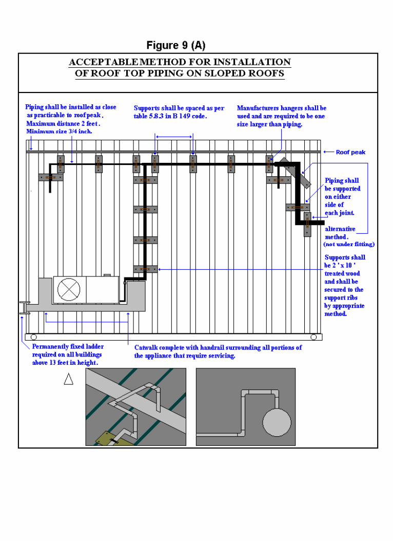
Refer to Figure 9 (A) for illustration of guardrail and anti-skid walkwaysurrounding equipment installed on a roof top.

Revised September 2000
Gas Notice 9 (A)Acceptable Method for Installation of Roof Top Piping on a Sloped Roof
Rationale: To illustrate acceptable methods of protecting gas piping installedoutdoors on a sloped roof from mechanical damage and/or stresses resultingfrom expansion and contraction caused by weather changes.
A sloped roof is one where water will drain to the outside perimeter of building.
Pipe support shall be provided according to Section 5.26.1 and Table 5.8.3 of thecurrent CSA B-149.1. The method of support shall be of a design acceptable tothe inspecting authority.
Refer to Figure 9 (A).

September 2001 addendum to replace Sept 2000 Gas Notice 9 (B)
Gas Notice 9 (B)Acceptable methods of pipe support on a flat roof
Rationale: To illustrate acceptable methods of protecting gas piping installedoutdoors on a flat roof from mechanical damage and/or stresses resulting fromexpansion and contraction caused by weather changes.
Pipe support shall be provided according to Section 5.26.1 and Table 5.8.3 of thecurrent CSA B-149.1. The method of support shall be of a design acceptable tothe inspecting authority.
Treated wood saw cuts shall be protected by end cut treatment.
Refer to Figure 9 (B) for acceptable methods of blocking.
Styrofoam Brand® SM Insulation or equivalent product supports treated to resistultra-violet rays are permitted in addition to the wood supports to protect roofingmaterial from damage by wood blocking.


Revised September 2000
Gas Notice 9 (C)Regulator stations on roof-tops
Rationale: To illustrate acceptable methods of protecting a gas regulator stationinstalled on a rooftop from snow and moisture.
Blocking methods shown in Figure 9 (C) Method 1 and Figure 9 (C) Method 2are for flat roofs. For proper blocking on sloped roofs refer to Figure 9 (A).
The regulator shall be installed and adequately supported to ensure the stationremains in its permanent position. The selected method of support shall alsoensure that the station is not affected by adverse weather conditions such aswind or snow load.
Care shall be exercised when selecting the location of the station to ensure thatno freezing water can drip on to the vent termination from another source (otherroof lines, eavestrough, drain pipes etc).

Figure 9 (C)Method 1
(a) Manufactured hangers or clamps shall be one size largerthan pipe diameter
(b) 4” X 4” treated wood block or other material acceptable tothe inspecting authority
(c) 2” X 10” treated wood block or other material acceptableto the inspecting authority
(d) Roof line(e) Union(f) Shut-off valve(g) Supports shall be provided at each threaded fitting(i) Regulator shall be supported on either side(j) Regulator shall be supported to prevent accidental
displacement and the vent shall terminate a minimum of 2feet (60 cm) above the roof line or higher than expectedsnow level, whichever is greater
(k) To appliance
Sept 2000

Figure 9 (C)Method 2
(a) Manufactured hangers or clamps shall be one size largerthan pipe diameter
(b) 4” X 4” treated wood block or other material acceptable tothe inspecting authority
(c) 2” X 10” treated wood block or other material acceptable tothe inspecting authority
(d) Roof line(e) Union(f) Shut-off valve(g) Supports shall be provided at each threaded fitting(h) Dirt pocket on vent line shall be 3 inch (7.5 cm) in depth.(i) Regulator shall be supported on either side.(j) Termination of vent pipe shall be fitted with a vent cap or
screen. Vent shall be supported to prevent accidentaldisplacement and shall terminate a minimum of 2 feetabove the roof line or higher than expected snow level,whichever is greater.
(k) To appliance.
Sept 2000

Revised September 2000
Gas Notice 9 (D)Semi-rigid tubing on roof-tops
Rationale: To illustrate acceptable methods of protecting semi-rigid gas tubinginstalled outdoors on a roof from mechanical damage and/or stresses resultingfrom expansion and contraction caused by weather changes.
Tubing laid on a rooftop shall be installed according to Section 5.26.2 and Table5.8.3 of the current CSA B-149.1 and shall be of a design acceptable to theinspecting authority.
Use proper blocking methods depending on roof design.
Tubing installed on a sloped roof shall be run within 2 feet of the peak.
Refer to Figure 9 (D).

Figure 9 (D) Sept 2000

Revised September 2000
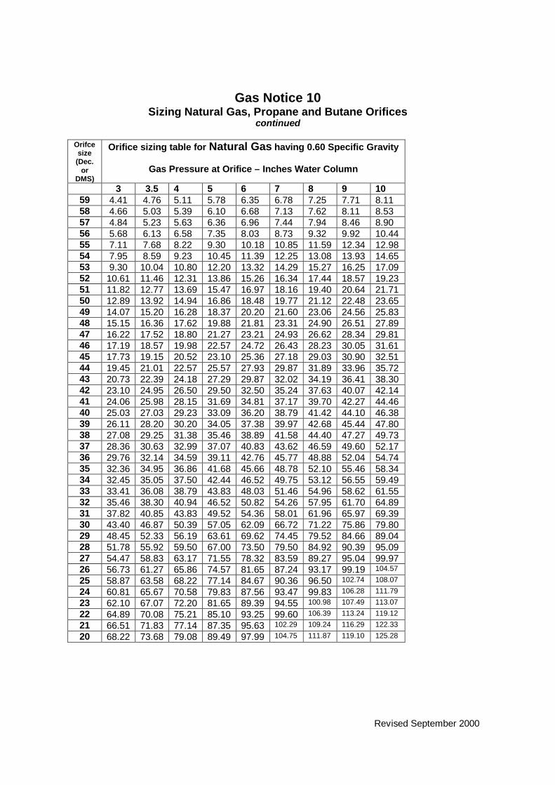
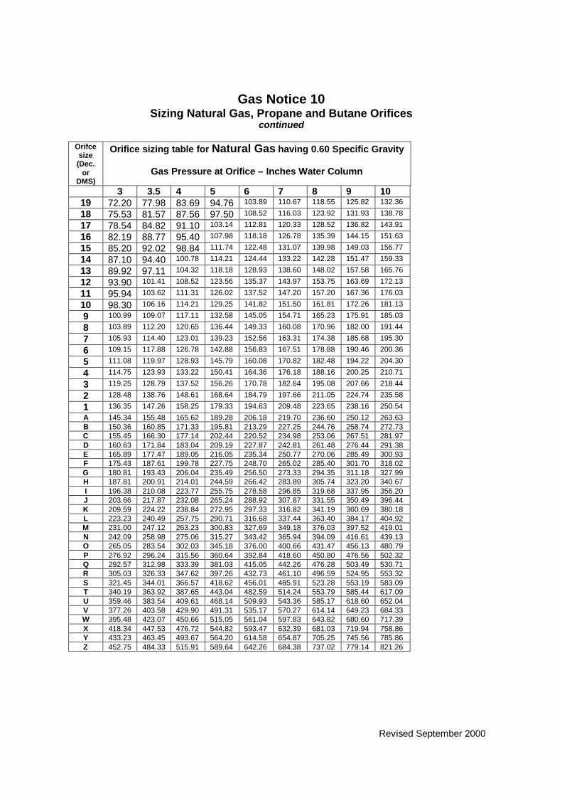
Gas Notice 10Sizing Natural Gas, Propane and Butane Orifices
Rationale: To provide orifice sizing information that is no longer available in theCSA B-149.1
To assist the gas fitter in computing the BTU rating of gas appliances, thefollowing orifice sizes may be used as a general guide for natural gas at thepressure indicated. Caution should be exercised in the use of the chart asvariations may occur depending on the design of the orifice.
Orificesize(Dec.
orDMS)
Orifice sizing table for Natural Gas having 0.60 SpecificGravity
Gas Pressure at Orifice – Inches Water Column3 3.5 4 5 6 7 8 9 10
0.008 .17 .18 .19 .23 .24 .26 .28 .29 .300.009 .21 .23 .25 .28 .30 .33 .35 .37 .390.010 .27 .29 .30 .35 .37 .41 .43 .46 .480.011 .33 .35 .37 .42 .45 .48 .52 .55 .590.012 .38 .41 .44 .50 .54 .57 .62 .65 .70
80 .48 .52 .55 .63 .69 .73 .79 .83 .8879 .55 .59 .64 .72 .80 .84 .90 .97 1.0178 .70 .76 .78 .88 .97 1.04 1.10 1.17 1.2477 .88 .95 .99 1.11 1.23 1.31 1.38 1.47 1.5576 1.05 1.13 1.21 1.37 1.52 1.61 1.72 1.83 1.9275 1.16 1.25 1.34 1.52 1.64 1.79 1.91 2.04 2.1474 1.33 1.44 1.55 1.74 1.91 2.05 2.18 2.32 2.4473 1.51 1.63 1.76 1.99 2.17 2.32 2.48 2.64 2.7872 1.64 1.77 1.90 2.15 2.40 2.52 2.69 2.86 3.0071 1.82 1.97 2.06 2.33 2.54 2.73 2.91 3.11 3.2670 2.06 2.22 2.39 2.70 2.97 3.16 3.38 3.59 3.7869 2.25 2.43 2.61 2.96 3.23 3.47 3.68 3.94 4.1468 2.52 2.72 2.93 3.26 3.58 3.88 4.14 4.41 4.6467 2.69 2.91 3.12 3.52 3.87 4.13 4.41 4.69 4.9466 2.86 3.09 3.32 3.75 4.11 4.39 4.68 4.98 5.2465 3.14 3.39 3.72 4.28 4.62 4.84 5.16 5.50 5.7864 3.41 3.68 4.14 4.48 4.91 5.23 5.59 5.95 6.2663 3.63 3.92 4.19 4.75 5.19 5.55 5.92 6.30 6.6362 3.78 4.08 4.39 4.96 5.42 5.81 6.20 6.59 6.9461 4.02 4.34 4.66 5.27 5.77 6.15 6.57 7.00 7.3760 4.21 4.55 4.89 5.52 5.95 6.47 6.91 7.35 7.74
Revised September 2000
Gas Notice 10Sizing Natural Gas, Propane and Butane Orifices
continued
Orifcesize(Dec.
orDMS)
Orifice sizing table for Natural Gas having 0.60 Specific Gravity
Gas Pressure at Orifice – Inches Water Column
3 3.5 4 5 6 7 8 9 1059 4.41 4.76 5.11 5.78 6.35 6.78 7.25 7.71 8.1158 4.66 5.03 5.39 6.10 6.68 7.13 7.62 8.11 8.5357 4.84 5.23 5.63 6.36 6.96 7.44 7.94 8.46 8.9056 5.68 6.13 6.58 7.35 8.03 8.73 9.32 9.92 10.4455 7.11 7.68 8.22 9.30 10.18 10.85 11.59 12.34 12.9854 7.95 8.59 9.23 10.45 11.39 12.25 13.08 13.93 14.6553 9.30 10.04 10.80 12.20 13.32 14.29 15.27 16.25 17.0952 10.61 11.46 12.31 13.86 15.26 16.34 17.44 18.57 19.2351 11.82 12.77 13.69 15.47 16.97 18.16 19.40 20.64 21.7150 12.89 13.92 14.94 16.86 18.48 19.77 21.12 22.48 23.6549 14.07 15.20 16.28 18.37 20.20 21.60 23.06 24.56 25.8348 15.15 16.36 17.62 19.88 21.81 23.31 24.90 26.51 27.8947 16.22 17.52 18.80 21.27 23.21 24.93 26.62 28.34 29.8146 17.19 18.57 19.98 22.57 24.72 26.43 28.23 30.05 31.6145 17.73 19.15 20.52 23.10 25.36 27.18 29.03 30.90 32.5144 19.45 21.01 22.57 25.57 27.93 29.87 31.89 33.96 35.7243 20.73 22.39 24.18 27.29 29.87 32.02 34.19 36.41 38.3042 23.10 24.95 26.50 29.50 32.50 35.24 37.63 40.07 42.1441 24.06 25.98 28.15 31.69 34.81 37.17 39.70 42.27 44.4640 25.03 27.03 29.23 33.09 36.20 38.79 41.42 44.10 46.3839 26.11 28.20 30.20 34.05 37.38 39.97 42.68 45.44 47.8038 27.08 29.25 31.38 35.46 38.89 41.58 44.40 47.27 49.7337 28.36 30.63 32.99 37.07 40.83 43.62 46.59 49.60 52.1736 29.76 32.14 34.59 39.11 42.76 45.77 48.88 52.04 54.7435 32.36 34.95 36.86 41.68 45.66 48.78 52.10 55.46 58.3434 32.45 35.05 37.50 42.44 46.52 49.75 53.12 56.55 59.4933 33.41 36.08 38.79 43.83 48.03 51.46 54.96 58.62 61.5532 35.46 38.30 40.94 46.52 50.82 54.26 57.95 61.70 64.8931 37.82 40.85 43.83 49.52 54.36 58.01 61.96 65.97 69.3930 43.40 46.87 50.39 57.05 62.09 66.72 71.22 75.86 79.8029 48.45 52.33 56.19 63.61 69.62 74.45 79.52 84.66 89.0428 51.78 55.92 59.50 67.00 73.50 79.50 84.92 90.39 95.0927 54.47 58.83 63.17 71.55 78.32 83.59 89.27 95.04 99.9726 56.73 61.27 65.86 74.57 81.65 87.24 93.17 99.19 104.57
25 58.87 63.58 68.22 77.14 84.67 90.36 96.50 102.74 108.07
24 60.81 65.67 70.58 79.83 87.56 93.47 99.83 106.28 111.79
23 62.10 67.07 72.20 81.65 89.39 94.55 100.98 107.49 113.07
22 64.89 70.08 75.21 85.10 93.25 99.60 106.39 113.24 119.12
21 66.51 71.83 77.14 87.35 95.63 102.29 109.24 116.29 122.33
20 68.22 73.68 79.08 89.49 97.99 104.75 111.87 119.10 125.28
Revised September 2000
Gas Notice 10Sizing Natural Gas, Propane and Butane Orifices
continued
Orifcesize(Dec.
orDMS)
Orifice sizing table for Natural Gas having 0.60 Specific Gravity
Gas Pressure at Orifice – Inches Water Column
3 3.5 4 5 6 7 8 9 1019 72.20 77.98 83.69 94.76 103.89 110.67 118.55 125.82 132.36
18 75.53 81.57 87.56 97.50 108.52 116.03 123.92 131.93 138.78
17 78.54 84.82 91.10 103.14 112.81 120.33 128.52 136.82 143.91
16 82.19 88.77 95.40 107.98 118.18 126.78 135.39 144.15 151.63
15 85.20 92.02 98.84 111.74 122.48 131.07 139.98 149.03 156.77
14 87.10 94.40 100.78 114.21 124.44 133.22 142.28 151.47 159.33
13 89.92 97.11 104.32 118.18 128.93 138.60 148.02 157.58 165.76
12 93.90 101.41 108.52 123.56 135.37 143.97 153.75 163.69 172.13
11 95.94 103.62 111.31 126.02 137.52 147.20 157.20 167.36 176.03
10 98.30 106.16 114.21 129.25 141.82 151.50 161.81 172.26 181.13
9 100.99 109.07 117.11 132.58 145.05 154.71 165.23 175.91 185.03
8 103.89 112.20 120.65 136.44 149.33 160.08 170.96 182.00 191.44
7 105.93 114.40 123.01 139.23 152.56 163.31 174.38 185.68 195.30
6 109.15 117.88 126.78 142.88 156.83 167.51 178.88 190.46 200.36
5 111.08 119.97 128.93 145.79 160.08 170.82 182.48 194.22 204.30
4 114.75 123.93 133.22 150.41 164.36 176.18 188.16 200.25 210.71
3 119.25 128.79 137.52 156.26 170.78 182.64 195.08 207.66 218.44
2 128.48 138.76 148.61 168.64 184.79 197.66 211.05 224.74 235.58
1 136.35 147.26 158.25 179.33 194.63 209.48 223.65 238.16 250.54A 145.34 155.48 165.62 189.28 206.18 219.70 236.60 250.12 263.63B 150.36 160.85 171.33 195.81 213.29 227.25 244.76 258.74 272.73C 155.45 166.30 177.14 202.44 220.52 234.98 253.06 267.51 281.97D 160.63 171.84 183.04 209.19 227.87 242.81 261.48 276.44 291.38E 165.89 177.47 189.05 216.05 235.34 250.77 270.06 285.49 300.93F 175.43 187.61 199.78 227.75 248.70 265.02 285.40 301.70 318.02G 180.81 193.43 206.04 235.49 256.50 273.33 294.35 311.18 327.99H 187.81 200.91 214.01 244.59 266.42 283.89 305.74 323.20 340.67I 196.38 210.08 223.77 255.75 278.58 296.85 319.68 337.95 356.20J 203.66 217.87 232.08 265.24 288.92 307.87 331.55 350.49 396.44K 209.59 224.22 238.84 272.95 297.33 316.82 341.19 360.69 380.18L 223.23 240.49 257.75 290.71 316.68 337.44 363.40 384.17 404.92M 231.00 247.12 263.23 300.83 327.69 349.18 376.03 397.52 419.01N 242.09 258.98 275.06 315.27 343.42 365.94 394.09 416.61 439.13O 265.05 283.54 302.03 345.18 376.00 400.66 431.47 456.13 480.79P 276.92 296.24 315.56 360.64 392.84 418.60 450.80 476.56 502.32Q 292.57 312.98 333.39 381.03 415.05 442.26 476.28 503.49 530.71R 305.03 326.33 347.62 397.26 432.73 461.10 496.59 524.95 553.32S 321.45 344.01 366.57 418.62 456.01 485.91 523.28 553.19 583.09T 340.19 363.92 387.65 443.04 482.59 514.24 553.79 585.44 617.09U 359.46 383.54 409.61 468.14 509.93 543.36 585.17 618.60 652.04V 377.26 403.58 429.90 491.31 535.17 570.27 614.14 649.23 684.33W 395.48 423.07 450.66 515.05 561.04 597.83 643.82 680.60 717.39X 418.34 447.53 476.72 544.82 593.47 632.39 681.03 719.94 758.86Y 433.23 463.45 493.67 564.20 614.58 654.87 705.25 745.56 785.86Z 452.75 484.33 515.91 589.64 642.26 684.38 737.02 779.14 821.26

Revised September 2000
Gas Notice 10Sizing Natural Gas, Propane and Butane Orifices
Continued
Orifice sizing table for Propane and Butane Gas11 inches Water Column (2.75 kPa)
Drill Size Orifice Capacity Btu/h (kW)Diameter (mm) Propane Butane80 (0.343) 1248 (0.3666) 1409 (0.413)79 (0.358) 1448 (0.413) 1635 (0.479)78 (0.406) 1769 (0.518) 1998 (0.585)77 (0.457) 2275 (0.666) 2570 (0.753)76 (0.508) 2842 (0.83) 3215 (0.94)75 (0.533) 3120 (0.91) 3544 (1.04)74 (0.572) 3624 (1.06) 4095 (1.2)73 (0.61) 4152 (1.22) 4690 (1.37)72 (0.635) 4510 (1.32) 5100 (1.49)71 (0.66) 4880 (1.43) 5508 (1.61)70 (0.711) 5660 (1.66) 6395 (1.9)69 (0.743) 6156 (1.8) 6950 (2)68 (0.787) 6940 (2.0) 7834 (2.3)67 (0.813) 7382 (2.2) 8340 (2.4)66 (0.838) 7853 (2.3) 8865 (2.6)65 (0.889) 8841 (2.6) 9975 (2.9)64 (0.914) 9350 (2.7) 10570 (3.1)63 (0.94) 9877 (2.9) 11160 (3.3)62 (0.965) 10420 (3.1) 11780 (3.5)61 (0.991) 10986 (3.2) 12400 (3.6)60 (1.02) 11540 (3.4) 13030 (3.8)59 (1.04) 12115 (3.5) 13700 (4)58 (1.07) 12720 (3.7) 14375 (4.2)57 (1.09) 13355 (3.9) 15080 (4.4)56 (1.18) 15600 (4.6) 17600 (5.2)55 (1.32) 19550 (5.7) 22120 (6.5)54 (1.4) 21960 (6.4) 24820 (7.3)53 (1.51) 25630 (7.5) 29000 (8.5)52 (1.61) 29220 (8.6) 33060 (9.7)51 (1.7) 32630 (9.6) 36840 (10.8)50 (1.78) 35730 (10.5) 40340 (11.8)49 (1.85) 38950 (11.4) 44100 (12.9)48 (1.93) 42375 (12.4) 47860 (14)47 (1.99) 45560 (13.3) 51500 (15.1)46 (2.06) 48900 (14.3) 55250 (16.2)45 (2.08) 50440 (14.8) 56830 (16.6)44 (2.18) 55500 (16.3) 62650 (18.4)43 (2.26) 59440 (17.4) 67160 (19.8)42 (2.37) 64620 (18.9) 74160 (21.7)41 (2.44) 69175 (20.2) 78150 (22.9)

Revised September 2000
Gas Notice 10Sizing Natural Gas, Propane and Butane Orifices
Continued
Orifice sizing table for Propane and Butane Gas11 inches Water Column (2.75 kPa)
Drill Size Orifice Capacity Btu/h (kW)Diameter (mm) Propane Butane40 (2.49) 72000 (21.1) 81400 (23.8)39 (2.53) 74380 (21.8) 84000 (24.6)38 (2.58) 77400 (22.7) 87400 (25.6)37 (2.64) 81125 (23.8) 91640 (26.9)36 (2.71) 85170 (25) 96150 (28.3)35 (2.79) 90600 (26.6) 102700 (30.1)34 (2.82) 92500 (27.1) 104500 (31)33 (2.87) 96000 (28.1) 108300 (31.7)32 (2.95) 100900 (29.6) 114000 (33.4)31 (3.05) 108125 (31.7) 122130 (35.8)
1/64 (0.397) 1686 (0.492) 1897 (0.556)1/32 (0.794) 7030 (2.1) 7935 (2.3)3/64 (1.19) 15960 (4.7) 17970 (5.3)1/16 (1.59) 28320 (8.3) 32000 (9.4)5/64 (1.98) 45150 (13.2) 51000 (14.9)3/32 (2.38) 65920 (19.3) 74500 (21.8)7/64 (2.78) 89825 (26.3) 101500 (29.7)1/8 (3.18) 117150 (34.3) 132400 (38.8)

Revised September 2000
Gas Notice 11 (A)Copper and Corrugated Stainless Steel Tubing for Residential Use
Rationale: To explain requirements to protect copper and corrugated stainlesssteel tubing systems from mechanical damage.
The following shall govern the installation of semi-rigid tubing and corrugatedpiping systems in residential and multiple-family dwellings.
Tubing Location and Protection1. Tubing may be run parallel, diagonal or at right angle to the floor joist. When
run parallel, it shall be fastened to the centre of the vertical face. When run atright angle or diagonally to the joists or partitions, it shall be installed throughdrilled holes as near as practicable to the centre of the joist. The diameter ofthe drilled hole shall be at least one and one half times as large as thediameter of the tubing. Alternatively, tubing may be run at right angles to thejoists by fastening to the underside of every second joist. Protection shall beprovided by conduit, duct work, centre beams. Where tubing is run in anopen area and where it is subject to mechanical damage, it shall be protectedby running a 1-inch dimensional lumber fastened adjacent to one side thetubing.
2. When tubing is installed inside a partition, a steel plate shall be used toprotect the tubing where it extends through the floor or top-plate or otherstructural member of the wall.
3. Tubing shall be protected with a plate at least 4 inches (100 mm) square ofnot less than 16 gauge steel when it passes through a stud, joist, plate orother structural member and where the tubing is less than 1 ¾ inches (45mm) from the exposed edge.
4. Concealed piping or tubing shall be installed where it can be inspected andtested in its final position prior to being concealed.
Corrugated Stainless Steel TubingWhere the current CSA B-149.1 capacity and pipe sizing tables do not provideinformation to size corrugated stainless steel tubing, the manufacturer’s certifiedinstructions for sizing shall be followed.
In all cases, when manufacturer’s installation instructions exceed theminimum requirements stated here, manufacturer’s instructions shall befollowed.

Revised September 2000
Gas Notice 11 (B)Copper and Corrugated Stainless Steel Tubing for Appliance Connections
Rationale: To explain requirements when using copper or corrugated stainlesssteel tubing for appliance connections.
Appliance Connections
1. When using copper or corrugated stainless steel tubing in piping systems toappliances such as furnaces, boilers and water heaters, the tubing shall beconnected directly to the appliance shut-off valve on the drop, upstream of thesteel dirt pocket. When this method is used, the tubing is to be attached tothe appliance casing. A union shall be provided to allow the burner or controlto be removed for servicing.
Refer to Figure 11 (C).
2. When using copper or corrugated stainless steel tubing in piping systems toappliances such as ranges and dryers, the appliance shall be connected tothe supply tubing with an approved flexible metal connector. The transitionfitting from the supply tubing to the flexible connector shall be fasteneddirectly to the building structure. Each appliance of the above type shall havean acceptable restraining device installed in a manner that will effectivelyprevent undue strain on the connector when moved.
3. Appliances such as space heaters, gas fireplaces and decorative appliancesmay be directly connected with copper or corrugated stainless steel tubing.These appliances shall be secured to prevent dislodgment of the vent. Theappliance shut-off valve shall be located per section 5.18 of the current CSAB-149.1.

Revised September 2000
Gas Notice 11 (C)
Rationale: To illustrate how to use slack when installing semi-rigid tubing toprovide adequate flexibility in the piping system.
Refer to Figure 11 (C).

Figure 11 (C)

Revised September 2000
Gas Notice 12Propane storage tanks on a construction site
Rationale: To explain minimum requirements for protection of a propane deliverysystem installed at a temporary site.
1. Permits and drawings must be submitted for approval to the Mechanical andEngineering Branch prior to installation of any propane storage tank.
2. Installation of propane storage tanks up to 2,000 gallon maximum capacitymust be at least 10 feet (3.05 m) from all buildings, hoardings, driveways andexcavations below grade.
3. All propane tank installations must be protected from vehicle traffic— 45 gallondrums filled with sand placed 4 feet (1.2 m) apart around the completepropane installation is acceptable.
4. All supply hoses from tank installations to buildings and hoarding must beprotected from damage. It is acceptable to use 2” X 4” lumber to protecthoses.
5. Any mobile propane tank used at a construction site must be adequatelyblocked, and the installation must be protected from physical damage by anacceptable method, such as that used to protect stationary propane tankinstallations.
6. Steel piping must be used where it passes through walls, floors and hoarding.Hoses are not allowed for these applications.
7. Gas shut-off valves are to be installed at building entrances and on all branchlines on piping manifolds supplying construction heaters.
8. The hose and any connectors used shall be approved for use by anrecognized approval agency. The hose shall be sized properly for the ratedinput of the construction heater being supplied. The hose shall not be lessthat 15 feet (4.6 m) nor more than 50 feet (16 m), per the current CSA B149.1Section 5.20.3 (c). No connections are allowed in the hose.

Revised September 2000
Gas Notice 13 (A)Sizing a manifold downstream of gas meter
Rationale: To explain requirements for sizing pipe immediately downstream ofthe gas meter so that there is adequate capacity to meet the maximum demandby branch lines to all downstream appliances.
Refer to Section 5.6.2 of current CSA B-149.1
Refer to Figure 13 (A).
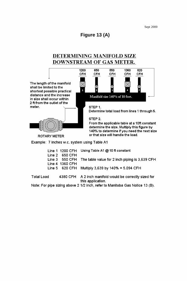
Figure 13 (A)
Sept 2000

Revised September 2000
Gas Notice 13 (B)Sizing pipe
Rationale: To provide fitters pipe sizing and capacity tables for pipe in diameters4 inches and over, which is no longer available in the current CSA B-149.1. Pipesizing and capacity tables contained in the current CSA B-149.1 shall be used tocalculate pipe size under 4 inch diameter
Table 1Maximum capacity of schedule 40 pipe in thousands of BTUH for a starting pressure up to 7inches Water Column with a maximum loss in pressure of 0.5 inches Water Column. Fittings arenot included. (based on a 0.60 Relative Density Gas)
Lengthof Pipe(feet)
Nominal Pipe Size in inches
4 5 6 810 20913 37835 61264 12587520 14374 26004 42107 8651330 11543 20882 33813 6947340 9879 17872 28940 5964050 8756 15840 25649 5269860 7933 14352 23240 4774870 7298 13204 21380 4392880 6790 12284 19890 4086690 6371 11525 18662 38344
100 6018 10887 17628 36219125 5333 9649 15624 32100150 4832 8742 14156 29085175 4446 8043 13032 26758200 4136 7482 12116 24893250 3666 6632 10738 22062300 3321 6009 9729 19900350 3056 5528 8951 18391400 2843 5143 8327 17109450 2667 4825 7813 16053500 2519 4558 7380 15163550 2393 4329 7009 14401600 2283 4130 6687 13739700 2100 3799 6152 12640800 1954 3534 5723 11759900 1833 3316 5370 110331000 1732 3133 5072 104221500 1390 2516 4073 83692000 1190 2153 3486 7163
Revised September 2000
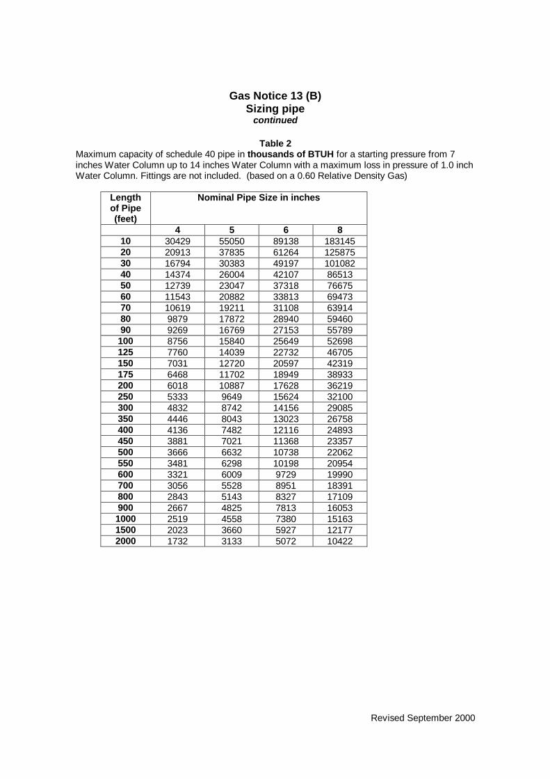
Gas Notice 13 (B)Sizing pipe
continued
Table 2Maximum capacity of schedule 40 pipe in thousands of BTUH for a starting pressure from 7inches Water Column up to 14 inches Water Column with a maximum loss in pressure of 1.0 inchWater Column. Fittings are not included. (based on a 0.60 Relative Density Gas)
Lengthof Pipe(feet)
Nominal Pipe Size in inches
4 5 6 810 30429 55050 89138 18314520 20913 37835 61264 12587530 16794 30383 49197 10108240 14374 26004 42107 8651350 12739 23047 37318 7667560 11543 20882 33813 6947370 10619 19211 31108 6391480 9879 17872 28940 5946090 9269 16769 27153 55789
100 8756 15840 25649 52698125 7760 14039 22732 46705150 7031 12720 20597 42319175 6468 11702 18949 38933200 6018 10887 17628 36219250 5333 9649 15624 32100300 4832 8742 14156 29085350 4446 8043 13023 26758400 4136 7482 12116 24893450 3881 7021 11368 23357500 3666 6632 10738 22062550 3481 6298 10198 20954600 3321 6009 9729 19990700 3056 5528 8951 18391800 2843 5143 8327 17109900 2667 4825 7813 160531000 2519 4558 7380 151631500 2023 3660 5927 121772000 1732 3133 5072 10422
Revised September 2000
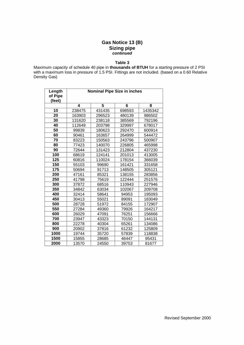
Gas Notice 13 (B)Sizing pipe
continued
Table 3Maximum capacity of schedule 40 pipe in thousands of BTUH for a starting pressure of 2 PSIwith a maximum loss in pressure of 1.5 PSI. Fittings are not included. (based on a 0.60 RelativeDensity Gas)
Lengthof Pipe(feet)
Nominal Pipe Size in inches
4 5 6 810 238475 431435 698593 143534220 163903 296523 480139 98650230 131620 238118 385569 79219640 112649 203798 329997 67801750 99839 180623 292470 60091460 90461 163657 264999 54447270 83223 150563 243796 50090780 77423 140070 226805 46599890 72644 131423 212804 437230
100 68619 124141 201013 413005125 60816 110024 178154 366039150 55103 99690 161421 331658175 50694 91713 148505 305121200 47161 85321 138155 283856250 41798 75619 122444 251576300 37872 68516 110943 227946350 34842 63034 102067 209708400 32414 58641 94953 195093450 30413 55021 89091 183049500 28728 51972 84155 172907550 27284 49360 79926 164217600 26029 47091 76251 156666700 23947 43323 70150 144131800 22278 40304 65261 134086900 20902 37816 61232 1258091000 19744 35720 57839 1188381500 15855 28685 46447 954312000 13570 24550 39753 81677

Revised September 2000
Gas Notice 13 (B)Sizing pipe
continued
Table 4Maximum capacity of schedule 40 pipe in thousands of BTUH for a starting pressure of 5 PSIwith a maximum loss in pressure of 2.5 PSI. Fittings are not included. (based on a 0.60 RelativeDensity Gas)
length ofPipe(feet)
Nominal Pipe Size in inches
4 5 6 810 375431 679208 1099795 225966020 258032 466816 755883 155305130 207209 374870 607001 124715540 177344 320840 519514 106740350 157177 284355 460436 94602060 142413 257646 417188 85716370 131018 237031 383808 78857980 121887 220512 357059 73362090 114363 206899 335017 688332
100 108027 195435 316455 650194125 95742 173211 280468 576255150 86749 156941 254125 522129175 79808 144384 233791 480352200 74246 134322 217498 446875250 65803 119047 192764 396057300 59622 107865 174658 358856350 54852 99234 160683 330143400 51029 92318 149485 307134450 47879 86619 140257 288174500 45226 81820 132486 272208550 42953 77708 125828 258528600 40978 74135 120042 246640700 37699 68203 110437 226905800 35072 63450 102740 211092900 32907 59533 96398 1980601000 31084 56235 91057 1870871500 24961 45158 73122 1502372000 21364 38650 62583 128584

Revised September 2000
Gas Notice 13 (B)continued
Table 5Maximum capacity of schedule 40 in thousands of BTUH for a starting pressure of 10 PSI with amaximum loss in pressure of 5 PSI. Fittings are not included. (based on a 0.60 Relative DensityGas)
length ofPipe(feet)
Nominal Pipe Size in inches
4 5 6 810 603785 1092332 1768738 363408220 414978 750754 1215644 249768430 333242 602882 976205 200572840 285212 515989 835505 171664450 252778 457311 740493 152143060 229053 414357 670940 137852670 210710 381203 617256 126826680 196025 354636 574238 117984090 183923 332743 538789 1107005
100 173733 314307 508936 1045670125 153976 278565 451061 926758150 139514 252400 408694 839710175 128351 232205 375993 772522200 119406 216022 349789 718683250 105827 191456 310012 636956300 95887 173473 280893 577128350 88215 159593 258418 530950400 82067 148471 240408 439947450 77001 139305 225567 463454500 72734 131587 213069 437776550 69079 124974 202361 415775600 65903 119227 193056 396567700 60630 109687 177609 364919800 56404 102043 165231 339487900 52922 95744 155031 3185291000 49990 90439 146441 3008811500 40144 72626 117598 2416182000 34358 62158 100648 206794

Revised September 2000
Gas Notice 13 (B)continued
Table 6Maximum capacity of schedule 40 in thousands of BTUH for a starting pressure of 20 PSI with amaximum loss in pressure of 10 PSI. Fittings are not included. (based on a 0.60 Relative DensityGas)
length ofPipe(feet)
Nominal Pipe Size in inches
4 5 6 810 1028373 1860471 3012533 618960520 706795 1278691 2070497 425408130 567581 1026834 1662682 341617740 485776 878837 1423041 292380650 430534 778897 1261215 259131560 390095 705737 1142752 234791970 358883 649269 1105317 216005680 333871 604020 978048 200951590 313260 566732 917670 1885462
100 295904 535332 866826 1780996125 262254 474455 768252 1578464150 237621 429890 696092 1430203175 218608 395494 640395 1315768200 203373 367930 595764 1224069250 180246 326090 528015 1084869300 163316 295461 478420 982970350 150248 271820 440140 904320400 139777 252877 409466 841295450 131148 237266 384188 789360500 123882 224120 362902 745625550 117656 212856 344664 708152600 112246 203069 328815 675590700 103265 186821 302506 621534800 96068 173801 281423 578218900 90137 163071 264050 5425231000 85143 154036 249420 5124641500 68373 123697 200293 4115262000 58519 105868 171425 352213

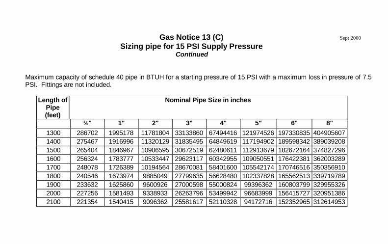
Gas Notice 13 (C)Sizing pipe for 15 PSI Supply Pressure
Rationale: To provide fitters a pipe sizing and capacity table for gas with a starting pressure of 15 psi, which isno longer available in the current CSA B-149.1.
Maximum capacity of schedule 40 pipe in BTUH for a starting pressure of 15 PSI with a maximum loss in pressure of 7.5 PSI.Fittings are not included.
Length ofPipe (feet)
Nominal Pipe Size in inches
½" 1" 2" 3" 4" 5" 6" 8"10 7013751 27557687 162731947 457649588 932242483 1684729508 2725561578 559261386950 1662139 11566936 68304356 192091724 391295154 707140583 1144014629 2347417917100 1143646 7958712 46997290 132170056 269233372 486553031 787147279 1615157340200 786894 5476047 32336815 90940533 185247907 334776221 541602199 1111320321300 632313 4400313 25984455 73075849 148857145 269011582 435207923 893008578400 541428 3767833 22249572 62572271 127461120 230345124 372653186 764651731500 480029 3340553 19726426 55476449 113006772 204223522 330393563 677938683600 435068 3027666 17878786 50280350 102422201 185095303 299447860 614440807700 400355 2786101 16452312 46268689 94250358 170327315 275556155 565417118800 372533 2592484 15308974 43053289 87700517 158490576 256406635 526123980900 349601 2432901 14366614 40403098 82302017 148734519 240623250 493737855
1000 330287 2298491 13572905 38170959 77755101 140517425 227329606 4664604591100 313736 2183311 12892751 36258168 73858703 133475934 215937855 4430855851200 299351 2083207 12301624 34595747 70472313 127356120 206037198 422770301
Sept 2000
Gas Notice 13 (C)Sizing pipe for 15 PSI Supply Pressure
Continued
Maximum capacity of schedule 40 pipe in BTUH for a starting pressure of 15 PSI with a maximum loss in pressure of 7.5PSI. Fittings are not included.
Length ofPipe(feet)
Nominal Pipe Size in inches
½" 1" 2" 3" 4" 5" 6" 8"1300 286702 1995178 11781804 33133860 67494416 121974526 197330835 4049056071400 275467 1916996 11320129 31835495 64849619 117194902 189598342 3890392081500 265404 1846967 10906595 30672519 62480611 112913679 182672164 3748272961600 256324 1783777 10533447 29623117 60342955 109050551 176422381 3620032891700 248078 1726389 10194564 28670081 58401600 105542174 170746516 3503569101800 240546 1673974 9885049 27799635 56628480 102337828 165562513 3397197891900 233632 1625860 9600926 27000598 55000824 99396362 160803799 3299553262000 227256 1581493 9338933 26263796 53499942 96683999 156415727 3209513862100 221354 1540415 9096362 25581617 52110328 94172716 152352965 312614953
Sept 2000

Revised September 2000
Gas Notice 14Flexible connectors
Rationale: To clarify requirements for using flexible connectors on moveable andstationary domestic appliances.
1. Flexible connectors for domestic movable appliances:(a) When using flexible connectors for appliances such as dryers, ranges etc.
these connectors shall comply with the current CGA 6.10/ANSI Z21.24“Metal connectors for gas appliances”. The minimum length shall be 3 feet(900 mm). Maximum length 6 feet (1.8 m)
(b) Each appliance of the above type shall have an acceptable restraining deviceinstalled in a manner that will effectively prevent undue strain on theconnector when the appliance is moved.
2. Flexible connectors for domestic stationary appliances:(a) Flexible connectors for domestic appliances shall comply with the current
CGA 6.10/ANSI Z21.24 “Metal connectors for gas appliances”. Themaximum allowable horizontal deflection from centre to centre is 1 1/2 inches.Refer to CSA B149.1 Section 5.21.3.
(b) When a flexible connector is installed on a water heater the connector shallfollow the contour of the appliance.
(c) A flexible connector may not pass through the walls of a cabinet unless it isapproved to do so and this approval is stated within the manufacturer’scertified installation instructions.
3. CGA Brazed-end flexible connectorsAll CGA brazed-end flexible connectors must be replaced when the appliancethey serve is being replaced.
All AGA flexible connectors must be replaced immediately.

Gas Notice 15 (A)Installation of buried steel pipe to supply residential outbuildings
Rationale: To illustrate general requirements for installation of buried steel gaspiping including the requirement to obtain a permit for all installations.
1. Due to the corrosive nature of the soil, steel gas piping, tubing or fittings laidunderground shall be protected against corrosion in accordance with goodengineering practice and in accordance with the manufacturer’s instructions.
2. Indicate clearly on the permit that the installation involves underground orconcealed pipe.
3. Utility shall inspect piping and witness pressure test prior to burial orconcealing.
Refer to Figure 15 (A)
Legend for Figure 15 (A)(A)I The minimum distance of lateral run shall be 12 inches (30 cm).
II An offset shall be incorporated into the swing to allow for ground settling orbuilding movement.
III The connection at the meter shall no t interfere with the Utility meter swing.
(B) A shut-off valve at point of exit and point of entry is required and shall be installedminimum 10 inches (25 cm) above grade.
(C) Piping shall be factory coated or double-wrapped.
(D) Connections shall be welded and stamped with the appropriate identification.Welding shall be done to an approved procedure and the welder shall hold anappropriate valid High Pressure Welders Licence issued by the Mechanical andEngineering Branch of Manitoba Labour.
(E) Minimum depth 15 inches (40 cm). Trench shall be properly graded with no dipsor sags. Backfill shall contain no sharp objects that can damage pipe.
(F) Anode shall be installed minimum 12 inches (30 cm) below level of the pipe andshall be attached to the riser by stainless steel clamp(s) above grade.
(G) Dielectric couplings or unions are required to isolate cathodic protection.
Note: Steel piping shall be tested and inspected prior to concealment. Pressure testsshall be conducted per B149 procedure and shall be witnessed by the Utility.
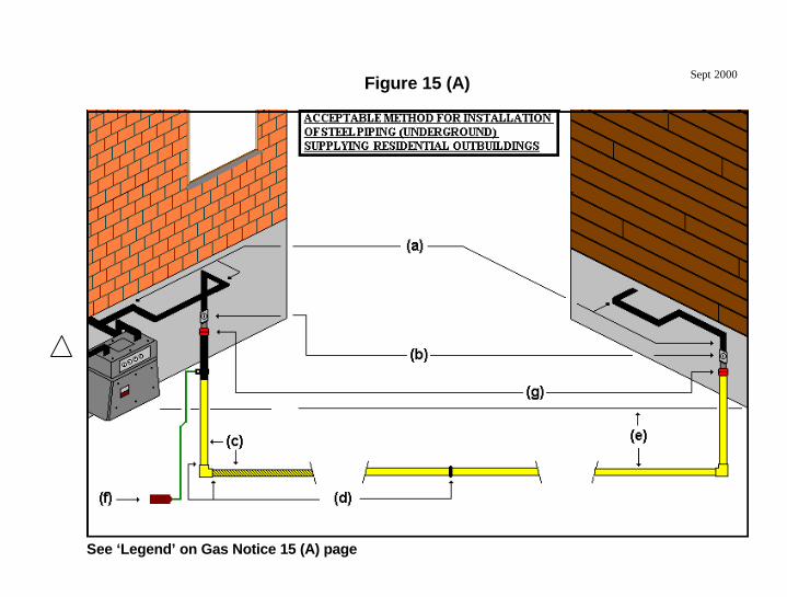
Figure 15 (A)
See ‘Legend’ on Gas Notice 15 (A) page
Sept 2000
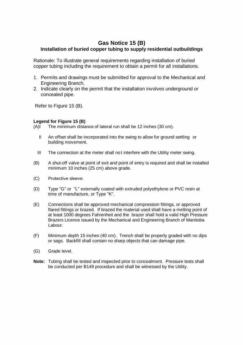
Gas Notice 15 (B)Installation of buried copper tubing to supply residential outbuildings
Rationale: To illustrate general requirements regarding installation of buriedcopper tubing including the requirement to obtain a permit for all installations.
1. Permits and drawings must be submitted for approval to the Mechanical andEngineering Branch.
2. Indicate clearly on the permit that the installation involves underground orconcealed pipe.
Refer to Figure 15 (B).
Legend for Figure 15 (B)(A)I The minimum distance of lateral run shall be 12 inches (30 cm).
II An offset shall be incorporated into the swing to allow for ground settling orbuilding movement.
III The connection at the meter shall no t interfere with the Utility meter swing.
(B) A shut-off valve at point of exit and point of entry is required and shall be installedminimum 10 inches (25 cm) above grade.
(C) Protective sleeve.
(D) Type "G" or "L" externally coated with extruded polyethylene or PVC resin attime of manufacture, or Type "K".
(E) Connections shall be approved mechanical compression fittings, or approvedflared fittings or brazed. If brazed the material used shall have a melting point ofat least 1000 degrees Fahrenheit and the brazer shall hold a valid High PressureBrazers Licence issued by the Mechanical and Engineering Branch of ManitobaLabour.
(F) Minimum depth 15 inches (40 cm). Trench shall be properly graded with no dipsor sags. Backfill shall contain no sharp objects that can damage pipe.
(G) Grade level.
Note: Tubing shall be tested and inspected prior to concealment. Pressure tests shallbe conducted per B149 procedure and shall be witnessed by the Utility.

Figure 15 (B)
See ‘Legend’ on Gas Notice 15 (B) page.

Gas Notice 15 (C)Installation of buried plastic pipe to supply residential outbuildings
Rationale: To illustrate general requirements regarding installation of buriedplastic tubing including the requirement to obtain a permit for all installations.
1. Permits and drawings must be submitted for approval to the Mechanical andEngineering Branch.
2. Indicate clearly on the permit that the installation involves underground orconcealed pipe.
Refer to Figure 15 (C).
Legend for Figure 15 (C)(A)I The minimum distance of lateral run shall be 12 inches (30 cm).
II An offset shall be incorporated into the swing to allow for ground settling orbuilding movement.
III The connection at the meter shall no t interfere with the Utility meter swing.
(B) A shut-off valve at point of exit and point of entry is required and shall be installedminimum 10 inches (25 cm) above grade. At point of exit, shut-off valve shall beidentified as to what outbuilding it serves.
(C) Anodeless risers, or steel risers with appropriate cathodic protection (anodes).
(D) Approved transition fittings.
(E) Connections shall be approved mechanical fittings or approved fusions. Allpersonnel performing fusions shall be certified in the applicable procedures bythe manufacturer or an organization acceptable to the inspecting authority. SeeManitoba Gas Notice 21.
(F) Minimum depth 15 inches (40 cm). Trench shall be properly graded with no dipsor sags. Backfill shall contain no sharp objects that can damage pipe.
(G) Grade level.
(H) If steel risers are used each riser shall have cathodic protection. The anodesshall be attached to the riser above grade by means of a clamp. Anodelessrisers do not require cathodic protection.
(I) Plastic piping shall be accompanied by a tracer wire throughout its entire lengthwhich shall terminate above grade.
Note: Plastic pipe shall be tested and inspected prior to concealment. For ploughedplastic pipe, refer to Gas Notice 21. Pressure tests shall be conducted per B149procedure and shall be witnessed by the Utility.
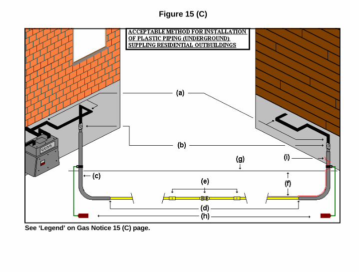
Figure 15 (C)
See ‘Legend’ on Gas Notice 15 (C) page.

Revised September 2000
Gas Notice 16Clarification of appliance vent termination
Rationale: To highlight and explain the difference between the current CSA B-149.1 Code requirements and minimum standards acceptable to Manitobainspecting authorities regarding appliance vent termination.
The current B149.1 allows an appliance vent to terminate directly over thecentre-line of a regulator providing that the appliance vent terminates at a heightof 15 feet or more above the meter/regulator assembly.
However, moisture in flue products may condense at the outlet of the vent in coldweather and there is potential for this condensation to drip down onto andinterfere with a regulator installed directly below.
Therefore, in Manitoba, an appliance vent must never terminate within 3 feet(900 mm) horizontally of the vertical centre of the regulator vent outlet.
Refer to Figure 16.

Figure 16

Revised September 2000
Gas Notice 17Unvented agricultural heaters
Rationale: To explain minimum requirements to provide adequate air changes inbuildings heated by unvented appliances.
Mechanical means of building ventilation must be interlocked with the heater toprevent the flow of gas to the burner on failure of airflow from building exhaustfan.
Rate of dedicated ventilation shall meet or exceed the appliance manufacturer‘srequirements as stated in the manufacturer’s certified instructions.
Refer to 6.21.1 and 6.21.2 of the current CSA B149.1.

Revised September 2000
Gas Notice 18Piping to commercial cooking equipment
Rationale: To explain general requirements for commercial cooking installations.
1. The in-line gas piping for commercial cooking equipment shall have readily-accessible shut-off valves installed for each appliance at either end of the in-line equipment.
2. The automatic fire safety valve shall be installed in a readily accessiblelocation outside of the protected canopy area.
3. Each individual appliance shut-off valve shall be identified as to the applianceit serves.
4. Appliance shut-off valves shall not be subjected to temperatures in excess of125 degrees Fahrenheit (50 degrees Celsius).
Refer to Figure 18.

Figure 18
(a) manual shut-off valve(b) union(c) automatic fire safety valve shall be installed in a readily accessible position outside the protected canopy area(d) readily accessible individual shut-off valve identified as to the appliance served shall not be subjected to temperatures in
excess of 125 F (50 C)
Sept 2000
Connections atappliances shall beinstalled according toB149.1 requirements.
Refer to B149.1Section 3.19.2

Revised September 2000
Gas Notice 19Street elbow fittings
Rationale: To clarify requirements for the removal of street elbow fittings fromexisting piping systems.
On replacement appliances, street elbows that are a part of the existing pipingsystem between the appliance shut-off valve and the appliance must be replacedwith acceptable fittings.
If piping prior to the shut-off valve is replaced or modified, all street elbows in themodified piping system shall be replaced with acceptable fittings.
Street elbows supplied and installed as part of an approved appliance are notpart of the piping system, and therefore do not have to be changed.

Revised September 2000
Notice 20Piped connections to mobile homes
Rationale: Guidance for installing acceptable swing joints where there is highprobability of structural shifting.
When installing a mobile home connection to a utility meter set, the swing jointrequired shall be a minimum 12 inches (30 cm) above grade, and minimum of a12 inches (30 cm) lateral from the building.
Refer to current CSA B149.1 Section 5.21.7, and to Figure 20.

Figure 20Sept 2000

Revised September 2000
Gas Notice 21Installing polyethylene pipe by ploughing and pushing
Rationale: Guidance for installing polyethylene pipe by ploughing and pushing.
General Requirements1. Polyethylene pipe intended for direct burial shall have a minimum thickness of
2.3 mm or greater in accordance with the requirements of CSA StandardCAN/CSA-B137.4.
2. Pipe on which saddle fusions are to be performed shall have a minimum wallthickness of 4.2 mm or greater in accordance with the requirements of CSAStandard CAN/CSA-B137.4.
3. The specific polyethylene pipe or tubing selected for use shall be adequatelyresistant to the fluids and chemical atmospheres that might be encountered.
4. Polyethylene pipe shall not be installed above ground.
5. Polyethylene piping or tubing shall be accompanied by a tracer wire or anequivalent medium. An acceptable method would be to use a minimum of 14-gauge wire as a means of pipeline location. Both ends of the wire shall beattached to the polyethylene pipe above grade with a minimum of 18 inches(450 mm) of wire left above grade.
6. Polyethylene pipe installed by ploughing methods shall not be bent duringinstallation to a radius less than the minimum recommended by themanufacturer for the particular pipe used.
7. Polyethylene pipe and fittings shall be joined by heat fusion, electro-fusion ormechanical methods. Such joining methods shall be compatible with thematerials being joined. Manufacturer’s instructions will be followed whenperforming heat fusion, electro-fusion and bonding in polyethylene pipingsystems. All personnel shall be certified in the applicable procedures by themanufacturer or an organization acceptable to the inspecting authority.
8. Joints in polyethylene piping systems shall be designedand installed to withstand longitudinal pullout forces caused by contraction ofthe pipes from external loading.
9A Polyethylene pipe fusion joints will not be classified as welded joints.9B Pressure test requirements per Table 5.22.2 CSA B-149.1
10. If the ploughing method is used, the installer shall leave all joints andconnections exposed to allow visual inspection by the inspection authority.

Revised September 2000
11. If the open trench method is used, the trench will be left open for fullinspection by the utility. The inspection authority will inspect tubing, tracerwire, and depth of trench per CSA B-149.1.
12. Random inspection of the integrity of tracer wire will be performed by theinspecting authority.
13. The connecting of short pieces of polyethylene pipe to form a longer run is prohibited.
14. Cathodic protection will be installed for any metallic parts of the system as necessary. Details about cathodic protection shall be provided on the installation permit.
Installers’ Responsibilities1. Plastic piping and tubing shall be inspected before installation for defects
such as cuts, scratches and gouges. Damaged cylindrical pieces shall be cutout and replaced. Inspection shall be adequate to confirm sound joints havebeen made. Refer to clause 5.27.1 of the current CSA B-149.1.
2. All joints and connections in plastic piping and tubing shall be visuallychecked for evidence of poor bonding. Where inspection reveals defectivejoints, they shall be cut out and replaced as per clause 5.27.2 of the CSA B-149.1.
3. Piping and tubing shall be located neither less than 15 inches (400 mm)underground nor less than 24 inches (600 mm) under a commercial drivewayor parking lot, except when it rises above ground at the point of supply toeither a building or an outdoor appliance. Additional depth of cover shall berequired where the piping is located in areas where physical damage is likelyto occur such as farm operations, per clause 5.15.4 of the CSA B-149.1.
4. The installer will be responsible for ensuring the integrity of the tracer wire
5. Polyethylene piping and tubing must be installed by a licensed gas fitter and apermit for installation of piping only is required from the Mechanical andEngineering Branch. All joints in the piping system must be done by acertified person.
6. The installer must provide drawings of the installation to the Mechanical andEngineering Branch prior to commencement of work.

Revised September 2000
Gas Notice 22Unvented residential space heaters and unvented decorative appliances
Unvented gas-fired residential space heaters and unvented gas-fired decorativeappliances shall not be used or installed in Manitoba unless certified by arecognized certifying agency.
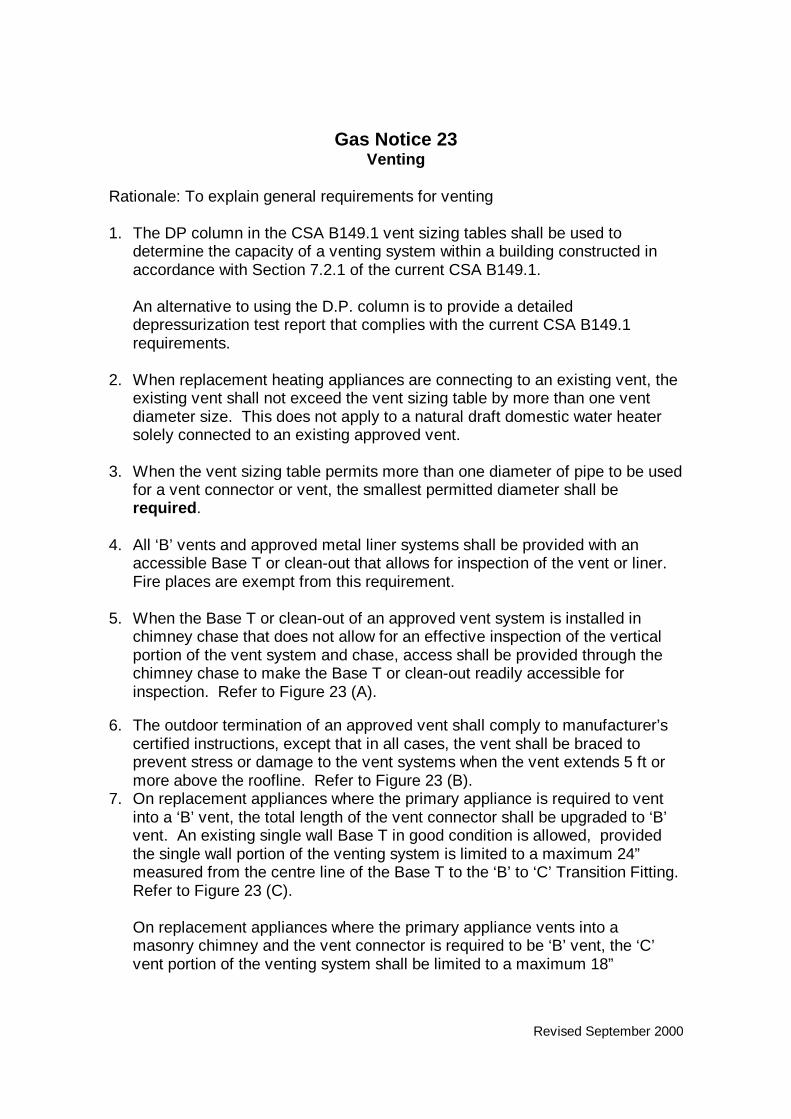
Revised September 2000
Gas Notice 23Venting
Rationale: To explain general requirements for venting
1. The DP column in the CSA B149.1 vent sizing tables shall be used todetermine the capacity of a venting system within a building constructed inaccordance with Section 7.2.1 of the current CSA B149.1.
An alternative to using the D.P. column is to provide a detaileddepressurization test report that complies with the current CSA B149.1requirements.
2. When replacement heating appliances are connecting to an existing vent, theexisting vent shall not exceed the vent sizing table by more than one ventdiameter size. This does not apply to a natural draft domestic water heatersolely connected to an existing approved vent.
3. When the vent sizing table permits more than one diameter of pipe to be usedfor a vent connector or vent, the smallest permitted diameter shall berequired.
4. All ‘B’ vents and approved metal liner systems shall be provided with anaccessible Base T or clean-out that allows for inspection of the vent or liner.Fire places are exempt from this requirement.
5. When the Base T or clean-out of an approved vent system is installed inchimney chase that does not allow for an effective inspection of the verticalportion of the vent system and chase, access shall be provided through thechimney chase to make the Base T or clean-out readily accessible forinspection. Refer to Figure 23 (A).
6. The outdoor termination of an approved vent shall comply to manufacturer’scertified instructions, except that in all cases, the vent shall be braced toprevent stress or damage to the vent systems when the vent extends 5 ft ormore above the roofline. Refer to Figure 23 (B).
7. On replacement appliances where the primary appliance is required to ventinto a ‘B’ vent, the total length of the vent connector shall be upgraded to ‘B’vent. An existing single wall Base T in good condition is allowed, providedthe single wall portion of the venting system is limited to a maximum 24”measured from the centre line of the Base T to the ‘B’ to ‘C’ Transition Fitting.Refer to Figure 23 (C).
On replacement appliances where the primary appliance vents into amasonry chimney and the vent connector is required to be ‘B’ vent, the ‘C’vent portion of the venting system shall be limited to a maximum 18”

Revised September 2000
measured from the wall of the masonry chimney to the ‘B’ to ‘C’ TransitionFitting. Refer to Figure 23 (D).

Figure 23 (A)Sept 2000

Figure 23 (B)
Sept 2000

Figure 23 (C) Sept 2000

Figure 23 (D) Sept 2000

Revised September 2000
Gas Notice 24Inspection of Heat Exchanger Failures
Rationale: To provide guidelines when inspecting a gas-fired heating appliancesuspected of having a cracked heat exchanger.
When checking for cracked heat exchangers, be sure to operate furnace for areasonable length of time (10 – 15 minutes) to allow heat exchanger to heatsufficiently.Face Plate Cracks1. Advise the owner of the defect if there is no flame disturbance. (Advise only)2. Small cracks may be repaired to stop air flow.3. Check for loose screws on face plates and diverted openings. Replace with
the next screw size larger.
Cracks or Hairline Fractures in heat exchangersRegardless of the apparent extent of the defect on discovery, all cracks andhairline fractures have the potential to become serious safety hazards.
Where there is no flame disturbance or evidence of carbon monoxide1. Advise the owner in writing of the crack or hairline fracture. Inform the
owner of the safety hazard.2. Advise owner that replacement is required per Section 3.21.1 current CSA
B149 Gas Installation Code.3. Notify the utility.4. Indicate the location of the hairline fracture directly on the appliance, or
by means of a sketch left on-site.
Where there is flame disturbance and/or evidence of carbon monoxide1. Immediately turn off appliance. Use a safe means of disconnecting the fuel
supply.2. Advise the owner in writing of the failure in the heat exchanger. Inform the
owner of the safety hazard.3. Advise owner that replacement is required per Section 3.21.1 current CSA
B149 Gas Installation Code.4. Notify the utility.5. Indicate the location of the defect directly on the appliance, or by means
of a sketch left on-site.

Gas Notice 25Clearances to a Natural Gas Utility Regulator
“A” 3 feet horizontally to (90 cm) gas appliance vent. See Gas Notice 16 andFigure 16.
“B” 3 feet (90 cm) to air intake for direct vent appliance.
“C” 3 feet (90 cm) to electrical panel, meter, outlet or air conditioning.
“D” 10 feet (3 m) to mechanical air intake.
“E” 3 feet (90 cm) to building opening, opening window.
“F” 3 feet (90 cm) to non-mechanical fresh air intake.
“G” 10 feet (3 m) to bar-b-que, open flame, pool heater, source of ignition.
“H” 3 feet (90 cm) to moisture duct (dryer vent termination).Distances per Centra Gas ‘Service Vent Termination’ Centra Standard 552.53

Revised September 2000
Questions and Answers
1. What if I have to deviate from code requirements because of a specificsituation in an installation?
A/ If you must deviate from code requirements, you require permission in writingfrom the inspecting authority before you proceed with your work. Ifpermission is given, it applies to that situation in that installation only. Youmust not assume that because you have been granted permission for adeviation, you can apply that deviation in another circumstance. Refer toclause 3.2.2 in the current CSA B-149.1.
2. What are the requirements for flexible connectors in public buildings?A/ A flexible connector shall not be used on a furnace or other gas-fired
appliance installed in a public building such as a school, church, curling rink,hall etc., where the general public has access to the appliance.
3. When can I install an appliance in a repair garage closer to the floor than 4.5feet (1.4 m)?
A/ When appliances are installed within an enclosure in a repair garage theappliance may meet the requirements for installation in a storage garageprovided that an automatic door closing device, a door sweep and adequatesealing around the door is installed. Air supply to the appliance shall meetrequirements of the code. Refer to clause 3.16.2 in the current CSA B-149.1.
4. Can I apply for special acceptance from the Mechanical and EngineeringBranch for a sandpan, log lighter or gas log that is not otherwise approved?
A/ No. The equipment must be approved by a recognized approval agency.The Mechanical and Engineering Branch will no longer give specialacceptance to non-approved sandpans.
5. What is the ’10-foot Rule’ when using copper and semi-rigid piping onfireplace installations?
A/ The last 10 feet to the fireplace may be sized as a 10-foot branch line as longas the main run had been sized properly according to the longest run.
6. How do I size a piping system that uses a combination of steel, copper andplastic pipe?
A/ Establish the total length of the longest run, even if the longest run is made upof sections consisting of more than one kind of piping material. Use thelongest run in the appropriate table to size the segments of each differentpipe material. For instance, if the longest run is ‘10 feet’, use ‘10 feet’ in thepipe size and capacity table for piping to size the steel/plastic segments pipeand also use ‘10 feet’ in the tubing size and capacity to size the coppersegments.
7. What is the minimum length of hot and cold air ducting required on a furnacein a house under construction?
Revised September 2000
A/ A furnace shall be fitted with hot and cold air plenums as per 6.13.5 (a) – (e)of the current CSA B-149.1.
8. Must free-standing fireplaces be fastened to the floor?A/ The appliance shall be secured to prevent dislodgment of the vent. Refer to
clause 5.21.6 of the current CSA B-149.1.
9. Can you use plastic pipe hangers to support copper piping?A/ No. Refer to clause 5.8.9 in the current CSA B-149.1.
10. Are there restrictions as to where I can locate a moisture duct?A/ Yes. A moisture duct shall be a minimum radius of three feet (900 mm) from
a service regulator and from any fresh air intake. A window or a door openingis considered to be a fresh air intake.
11. Who is responsible for monitoring cathodic protection on yard piping?A/ Monitoring cathodic protection is the customer’s responsibility.
12. Can I use a potable water heater for space heating?A/ Only if the manufacturer’s certified instructions indicate that a recognized
approval agency has approved the appliance to be used for either purpose.Most appliances do not have dual-use approval.
13. Are flexible connectors acceptable for use with fireplaces?A/ Flexible connectors are allowed if they are installed as per the appliance
manufacturers installation instructions.
14. Can flexible connectors used with a fireplace come through fireplace cabinet?A/ A flexible connector may not pass through the walls of
a cabinet unless it is approved to do so and this approval is stated within themanufacturer’s certified installation instructions. See Gas Notice 14.
15. Can a vent connector serving a fan assist appliance without dilution air butapproved for use with a ‘B’ type vent be constructed according to Section7.18.3 of the current CSA B-149.1?
A/ Yes; however in all cases, when manufacturer’s certified installation instructions exceed the minimum requirements stated here and in the current CSA B149.1, the manufacturer’s instructions shall be followed.
16. What type of copper fittings can be used for natural gasinstallations?
A/ For outdoor or underground use, only approved type Forged Nut Short Standard and Forged Nut Short Type fittings shall be used. All approved type forged and milled nut fittings may be used in indoor installations.

September 2001 addendum to add to Sept 2000 Gas Notice Q/A
Questions and AnswersContinued
17. Does it matter how quick disconnect gas valves are positioned?A/ Quick disconnect gas valves approved for outdoor installation for use with
portable outdoor appliances must be installed so that rain and moisturecannot pool in the valve body. Valves must be installed facing downwards ona 90 to 45 degree angle.