MANAGEMENT FLOW CONTROL ROTOR INDUCTION MACHINE USING...
6
© copyright FACULTY of ENGINEERING ‐ HUNEDOARA, ROMANIA 459 1. Stela RUSU-ANGHEL, 2. Lucian GHERMAN MANAGEMENT FLOW CONTROL ROTOR INDUCTION MACHINE USING FUZZY REGULATORS 1-2. UNIVERSITY POLITEHNICA OF TIMISOARA, FACULTY OF ENGINEERING FROM HUNEDOARA, ROMANIA ABSTRACT: Commands based on static characteristics of induction motor inevitably produce a number of undesirable effects on the dynamic behavior of the engine. These disadvantages can be partially eliminated by appealing to the orientation control strategy flow. The paper proposes the use of fuzzy controllers for rotor flow and electromagnetic torque, and simulation in Matlab-Simulink them. The results show that using fuzzy controllers compared with conventional methods allow a quick start and a small error rate in both task and goal. KEYWORDS: fuzzy controllers, Matlab-Simulink, induction motor INTRODUCTION Perturbations introduced by the inverter are most stator voltage and stator flow so. Instead, the rotor flow does not vary depending on the stator current with a time constant Tr so great. Vector diagram in Figure 1.1 describes the principle of rotor flow orientation with respect. Also the rotor flow estimation and adjustment can be made with a larger sampling period than the average of Stroke inverter. So after the rotor flow orientation allows us to combine the requirements in terms of rapidity and computing performance. In addition to orientation relative to the rotor flow, allows decoupling of flow and electromagnetic torque regulation. Ψ r rotor flow vectors and stator current is moving at the speed of the mobile coordinate system ω s synchronism. It is found that the flow vector is in phase with the real component of stator current phasor i sα and therefore is out of phase by 90 degrees from the imaginary component i sβ . Also, the rotor flow is purely real ( ) r r r , 0 α β ψ =ψ ψ = in mobile reference system. I sα real component of current flow while producing so imaginary component i sβ produce electromagnetic torque. Because of this dynamic coupling of the engine components are independent in terms of operation. Flow and torque can also be ordered individually. In Figure 1 is a circuit schematic diagram of power, control and control of a controlled induction motor rotor relative to the flow. Logic control signals, but (i = 1 ... 6) are determined from the adjustment phase currents. In principle, adjusting the phase currents are made just like the current order - variable stator frequency. Phase current shape is determined by the block (6) by making measurements i sα and i sβ mobile reference system fixed reference system with stator frequency f s estimated. Rotor flow adjustment is achieved through a flow regulator which is maintained by negative reaction to the amount imposed. RΨ flow controller output will give us the desired shape of the real component of current i cα , while the desired shape for the imaginary component icβ current signal is Figure 1. The schematic diagram of a control circuit after the rotor flow oriented
Transcript of MANAGEMENT FLOW CONTROL ROTOR INDUCTION MACHINE USING...

© copyright FACULTY of ENGINEERING ‐ HUNEDOARA, ROMANIA 459
1. Stela RUSU-ANGHEL, 2.Lucian GHERMAN
MANAGEMENT FLOW CONTROL ROTOR INDUCTION MACHINE USING FUZZY REGULATORS
1-2. UNIVERSITY POLITEHNICA OF TIMISOARA, FACULTY OF ENGINEERING FROM HUNEDOARA, ROMANIA
ABSTRACT: Commands based on static characteristics of induction motor inevitably produce a number of undesirable effects on the dynamic behavior of the engine. These disadvantages can be partially eliminated by appealing to the orientation control strategy flow. The paper proposes the use of fuzzy controllers for rotor flow and electromagnetic torque, and simulation in Matlab-Simulink them. The results show that using fuzzy controllers compared with conventional methods allow a quick start and a small error rate in both task and goal. KEYWORDS: fuzzy controllers, Matlab-Simulink, induction motor
INTRODUCTION
Perturbations introduced by the inverter are most stator voltage and stator flow so. Instead, the
rotor flow does not vary depending on the stator current with a time constant Tr so great. Vector diagram in Figure 1.1 describes the principle of rotor flow orientation with respect. Also the rotor flow estimation and adjustment can be made with a larger sampling period than the average of Stroke inverter.
So after the rotor flow orientation allows us to combine the requirements in terms of rapidity and computing performance. In addition to orientation relative to the rotor flow, allows decoupling of flow and electromagnetic torque regulation.
Ψr rotor flow vectors and stator current is moving at the speed of the mobile coordinate system ωs synchronism. It is found that the flow vector is in phase with the real component of stator current phasor isα and therefore is out of phase by 90 degrees from the imaginary component isβ. Also, the rotor
flow is purely real ( )r rr, 0α βψ = ψ ψ =
in mobile reference system. Isα real component of current flow while producing so imaginary component isβ produce electromagnetic torque. Because of this dynamic coupling of the engine components are independent in terms of operation. Flow and torque can also be ordered individually.
In Figure 1 is a circuit schematic diagram of power, control and control of a controlled induction motor rotor relative to the flow. Logic control signals, but (i = 1 ... 6) are determined from the adjustment phase currents. In principle, adjusting the phase currents are made just like the current order - variable stator frequency. Phase current shape is determined by the block (6) by making measurements isα and isβ mobile reference system fixed reference system with stator frequency fs estimated.
Rotor flow adjustment is achieved through a flow regulator which is maintained by negative reaction to the amount imposed. RΨ flow controller output will give us the desired shape of the real component of current icα, while the desired shape for the imaginary component icβ current signal is
Figure 1. The schematic diagram of a control circuit
after the rotor flow oriented

ANNALS OF FACULTY ENGINEERING HUNEDOARA – International Journal Of Engineering
Tome IX (Year 2011). Fascicule 3. ISSN 1584 – 2673 460
calculated from the speed controller output obtained from MC and the estimated value of rotor flow Bloc (9). This calculation is derived from the expression of electromagnetic torque as:
he r s
r
xm ix β= ⋅ψ ⋅
(1.1) Size mc prescribed torque comes from the speed controller, while the constant flow is imposed
(Ψrc = Ψrn) to ensure maximum torque reserve. Rotor flow can also be imposed under the principle of reducing the field to high rotational speeds. By overlaying the speed and position regulator allows adjustment of the induction motor speed and position.
Current regulator can be relised in the rotor coordinate system with the advantage that steady state values of stator current required icα and icβ are constant and independent of the stator frequency fs.
FUZZY CONTROL
As we know, the engine parameters vary depending on the magnetic circuit saturation regime
and temperature are also the dispersion due to their manufacturing process. To control the orientation of the
induction motor rotor flow will be used two fuzzy controllers, one for controlling the flow through the rotor stator current isα real component and a second controller to control the electromagnetic torque, so the rotational speed through the imaginary component isβ stator current. Block diagram of rotor flow control the orientation using fuzzy controllers is presented in Figure 2.
Numerical simulation was done in Matlab - Simulink using real data of a 133Hz engine. The mathematical model of rotor flow control the orientation is shown in Figure 2.3., And the induction motor model used in this type of order is shown in Figure 3.
Obtained speed at the exit block that models the asynchronous motor (Figure 1.4.) Block is applied to determine the rotor flow imposed, which is then limited to the nominal value of rotor flow. Using the rotor flow modulus value obtained in the block that models the asynchronous motor and the rotor flow value imposed by loss of control error to determine the rotor flow will apply fuzzy controller that will calculate the real component of stator current isα, which would apply to model induction motor.
Isβ imaginary component of stator current is determined by the second fuzzy controller based on speed error.
DESIGNING FUZZY CONTROLLERS –
FUZZY REGULATOR FOR FLOW ROTOR
Ψr rotor flow is controlled by the real component of stator current isα. The block diagram of this controller is shown in Figure 5.
Ψr rotor flow current value is taken from the induction motor model, but in practice it can be determines the stator currents depending on the stage. Rotor flow Ψrc prescribed value is determined using the rotational speed, not based on static characteristics. The estimated value of rotor flow is calculated.
Figure 2. Order flow target rotor block diagram,
using fuzzy controllers
Figure 3. The Matlab Simulink controlled induction motor
after the flow rotor oriented
Figure 4. The Matlab Simulink-controlled induction motor
rotor flow oriented by using fuzzy controllers
ANNALS OF FACULTY ENGINEERING HUNEDOARA – International Journal Of Engineering
© copyright FACULTY of ENGINEERING ‐ HUNEDOARA, ROMANIA 461
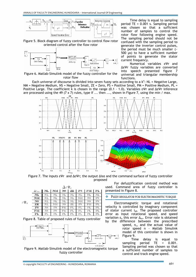
Time delay is equal to sampling period TE = 0.001 s. Sampling period was chosen so that a sufficient number of samples to control the rotor flow following engine speed. The sampling period should not be confused with the sampling period to generate the inverter control pulses, the period must be much smaller (~ 500 μs) to have a sufficient number of points to generate the stator current frequency.
Numerical variables εΨr and ΔεΨr fuzzy variables are converted into speech presented figure 7 universal and triangular membership functions.
Each universe of discourse is divided into seven fuzzy sets according to a kn: NL = Negative Large, NM = Negative Medium, NS = Negative Small, ZE = Zero, PS = Positive Small, PM = Positive Medium, PL = Positive Large. The coefficient k is chosen in the range (0.1 - 1.0). Variables εΨr and ΔεΨr inference are processed using the 49 (7 x 7) rules, type If ... then ..., shown in Figure 7, using the min / max.
Figure 7. The inputs εΨr and ΔεΨr; the output Δisα and the command surface of fuzzy controller
proposed For defuzzification centroid method was
used. Command area of fuzzy controller is presented in Figure 8.
FUZZY REGULATOR FOR ELECTROMAGNETIC TORQUE
Electromagnetic torque and rotational
velocity is controlled by imaginary component of stator current isβ. The proposed controller error as input rotational speed, and speed variation εn this error Δεn. Error rate is obtained by the difference between the prescribed
speed, nc, and the actual value of rotor speed n - Matlab Simulink model of this controller is shown in Figure 9.
Time delay is equal to sampling period TE = 0.001. Sampling period was chosen so that a sufficient number of samples to control and track engine speed.
Figure 5. Block diagram of fuzzy controller to control flow rotor
oriented control after the flow rotor
Figure 6. Matlab-Simulink model of the fuzzy controller for the
rotor flow
Figure 8. Table of proposed rules of fuzzy controller
Figure 9. Matlab-Simulink model of the electromagnetic torque
fuzzy controller
ANNALS OF FACULTY ENGINEERING HUNEDOARA – International Journal Of Engineering
Tome IX (Year 2011). Fascicule 3. ISSN 1584 – 2673 462
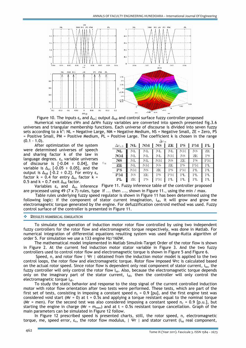
Figure 10. The inputs εn and Δεn; output Δisβ and control surface fuzzy controller proposed
Numerical variables εΨn and ΔεΨn fuzzy variables are converted into speech presented fig.3.6 universes and triangular membership functions. Each universe of discourse is divided into seven fuzzy sets according to a kn: NL = Negative Large, NM = Negative Medium, NS = Negative Small, ZE = Zero, PS = Positive Small, PM = Positive Medium, PL = Positive Large. The coefficient k is chosen in the range (0.1 - 1.0).
After optimization of the system were determined universes of speech and sharing factor k of the law in language degrees. εn variable universes of discourse is [-0.04 ÷ 0.04], the variable is Δεn [-0.05 ÷ 0.05], and the output is Δisβ [-0.2 ÷ 0.2]. For entry εn factor k = 0.4 for entry Δεn factor k = 0.5 and k = 0.7 exit Δisβ factor.
Variables εn and Δεn inference are processed using 49 (7 x 7) rules, type If ... then ..., shown in Figure 11., using the min / max.
Table rules underlying fuzzy speed regulator is shown in Figure 11 has been determined using the following logic: if the component of stator current imagination, isβ, it will grow and grow me electromagnetic torque generated by the engine. For defuzzification centroid method was used. Fuzzy control surface of the controller is presented in Figure 11.
RESULTS NUMERICAL SIMULATION
To simulate the operation of induction motor rotor flow controlled by using two independent
fuzzy controllers for the rotor flow and electromagnetic torque respectively, was done in Matlab. For numerical integration of differential equations resulting system was used Runge-Kutta algorithm of order 5. For simulation we use a 133 engine Hz/160W.
The mathematical model implemented in Matlab Simulink-Target Order of the rotor flow is shown in Figure 2. At the current fed induction motor stator variable in Figure 3. And the two fuzzy controllers used to control rotor flow and electromagnetic torque is shown in Figure 5 and Figure 6.
Speed, n, and rotor flow | Ψr | obtained from the induction motor model is applied to the two control loops, the rotor flow and electromagnetic torque. Rotor flow imposed Ψrc is calculated based on the actual rotor speed. Since rotor flow is dependent only real component of stator current, isα, the fuzzy controller will only control the rotor flow Isα. Also, because the electromagnetic torque depends only on the imaginary part of the stator current, isβ, then the controller will only control the electromagnetic torque isβ.
To study the static behavior and response to the step signal of the current controlled induction motor with rotor flow orientation after two tests were performed. These tests, which are part of the first set of tests, consisting in imposing a constant speed nc = 0.9 [pu], and the first engine test was considered void start (Mr = 0) at t = 0.5s and applying a torque resistant equal to the nominal torque (Mr = men). For the second test was also considered imposing a constant speed nc = 0.9 [p.u.], but starting the engine in charge (Mr = mmen) and at t = 0.5s resistant torque cancellation. Graph of the main parameters can be simulated in Figure 12 follow.
In Figure 12 prescribed speed is presented charts, still, the rotor speed, n, electromagnetic torque, me, speed error, εn, the rotor flow modulus, | Ψr | and stator current (isα real component,
Figure 11. Fuzzy inference table of the controller proposed

ANNALS OF FACULTY ENGINEERING HUNEDOARA – International Journal Of Engineering
© copyright FACULTY of ENGINEERING ‐ HUNEDOARA, ROMANIA 463
imaginary component and module isβ | is | the first set of tests. From these graphs you can see a great variation in the behavior of the prescribed speed gear so the engine speed error in the gap, and with the engine load.
Figure 12. Speed n electromagnetic torque me, rotor flow module | Ψr |, εn speed error and stator
current (real part isα, isβ imaginary component and module is) the first set of tests The transitional arrangement is very short settling speed prescribed in 0.14 and up, without a
long-harmonic regime. Study the dynamic regime controlled induction motor operation in the stator current with rotor flow orientation was made after the imposition of a speed, yet, to form sinusoidal amplitude 0.2 [p.u.] and the frequency of 6Hz. Frequency was chosen maximum speed acceleration imposed.
Figure 13. Rotor speed n, rpm still imposed, and the speed error εn 1 test 2 test kit
Otherwise that is approximately equal to the maximum acceleration that the engine can have rated load. For the first test of this set of tests, Figure 13 we considered to start in goal, (Mr = 0), and applying a torque at t = 0.5s electromagnetic torque is equal to the nominal resistance, and for the second test, Figure 14 , To start the task (Mr = men) and at t = 0.5s, strong torque cancellation.
From the study of dynamic graphics system (Figure 15) shows that using fuzzy controllers to get a quick start and a small error rate in both task and goal. The principle of command guidance after the rotor flow using fuzzy proposed to impose independent stator current components, compared with the methods described above, and leads to obtain very good results both in steady and dynamic conditions.

ANNALS OF FACULTY ENGINEERING HUNEDOARA – International Journal Of Engineering
Tome IX (Year 2011). Fascicule 3. ISSN 1584 – 2673 464
Figure 14. Rotor speed n, rpm still imposed, and the speed error εn Test 2 of 2 set of tests.
Figure 15. Variation of stator current phasor module, | is |, is the stator current phasor, the
rotor flow phasor module, | Ψr | and electromagnetic torque, me 2 test kit.
CONCLUSIONS
It can highlight the following conclusions: asynchronous motor is a nonlinear system described by a 7-order differential equations with variable parameters, the inverter, the control algorithm and the limitations imposed on the hysteresis, inter switching times is also a powerful nonlinear, speed control motors, control methods studied impugn regulators with variable coefficients depending on the operating point of engine controllers to drive motors implementation requires knowledge of how real operating parameters, and their evolution, the parameters may vary The magnetic circuit saturation and / or temperature, quality tuning fuzzy actually requires a wider range of motion controllers used in applications for robotics, machine tools, transportation, etc.
REFERENCES
[1.] Gelu-Ovidiu Tirian, Stela Rusu-Anghel – Automatizarea Proceselor Continue, Editura Mirton, Timisoara, 2008 [2.] Anghel Stela, Tirian Gelu-Ovidiu – Teoria Sistemelor si Reglaj Automat, Aplicatii in Matlab, Editura Mirton,
Timisoara, 2007 [3.] Peter Vas. Electrical machines and Drives – a Space – Vector Theory Approach, Volume 25 of Monographs in
electrica land Electronical Engineering. Oxford science Publications, Waltron Street, Oxford OX2 6DP, 1992. [4.] Fariba Moghaddam Butzberg. Etude et Comparaison de Differentes Strategies de Reglage et de Commande de
Servomoteurs Asynchrones. These no. 1414 pour l’obtention du grande de docteures sciences techniques, Ecole polytechnique federale de Lausanne, Department d’Electricite, 1995.
ANNALS OF FACULTY ENGINEERING HUNEDOARA
– INTERNATIONAL JOURNAL OF ENGINEERING copyright © University Politehnica Timisoara,
Faculty of Engineering Hunedoara, 5, Revolutiei, 331128, Hunedoara,
ROMANIA http://annals.fih.upt.ro
![Squirrel-Cage Rotor Options for AC Induction Motors[1]](https://static.fdocuments.in/doc/165x107/553c93a84a7959727a8b49ab/squirrel-cage-rotor-options-for-ac-induction-motors1.jpg)