
Making MIMO Measurements--Choosing and Using Tools · PDF fileMIMO & Measurements Overview ......
25
1 Making MIMO Measurements--Choosing and Using Tools March 2009 © Copyright 2009 Agilent Technologies, Inc. © Agilent Technologies Inc. 2009 Making MIMO Meas--Using & Choosing Tools March 2009 2 This Presentation Design & Measurement Tasks, Goals Performance Required Functionality Required • RF measurements: spectrum, power, timing, phase noise • Digital Demod: Basic mod quality or detailed analysis & troubleshooting • Number of inputs required: 1? 2? 3? 4? More? • System/subsystem or component test Leveraging & Upgrading Existing Solutions Using and Choosing Measurement Solutions
-
Upload
hoangthuan -
Category
Documents
-
view
215 -
download
0
Transcript of Making MIMO Measurements--Choosing and Using Tools · PDF fileMIMO & Measurements Overview ......

1
Making MIMO Measurements--Choosing
and Using Tools
March 2009
© Copyright 2009 Agilent Technologies, Inc.
© Agilent Technologies Inc. 2009 Making MIMO Meas--Using & Choosing Tools
March 20092
This Presentation
Design & Measurement Tasks, Goals
Performance Required
Functionality Required
• RF measurements: spectrum, power, timing, phase noise
• Digital Demod: Basic mod quality or detailed analysis & troubleshooting
• Number of inputs required: 1? 2? 3? 4? More?
• System/subsystem or component test
Leveraging & Upgrading Existing Solutions
Using and Choosing Measurement Solutions
2
© Agilent Technologies Inc. 2009 Making MIMO Meas--Using & Choosing Tools
March 20093
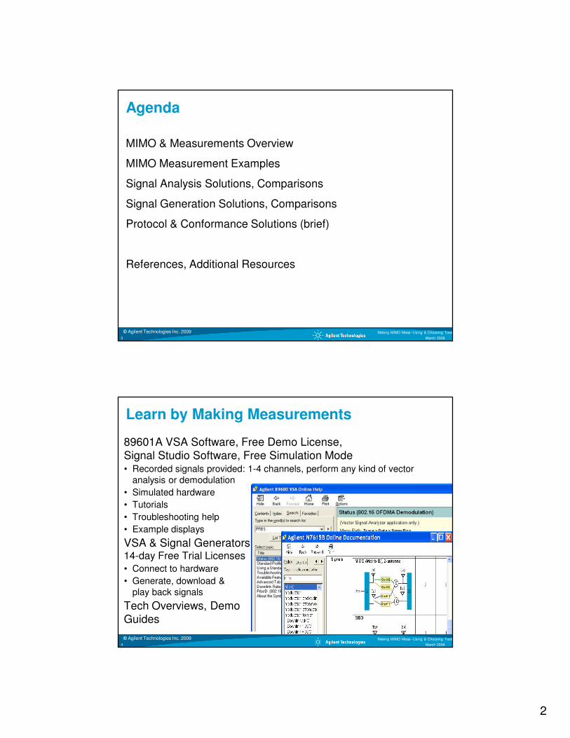
Agenda
MIMO & Measurements Overview
MIMO Measurement Examples
Signal Analysis Solutions, Comparisons
Signal Generation Solutions, Comparisons
Protocol & Conformance Solutions (brief)
References, Additional Resources
© Agilent Technologies Inc. 2009 Making MIMO Meas--Using & Choosing Tools
March 20094
Learn by Making Measurements
89601A VSA Software, Free Demo License, Signal Studio Software, Free Simulation Mode• Recorded signals provided: 1-4 channels, perform any kind of vector
analysis or demodulation
• Simulated hardware
• Tutorials
• Troubleshooting help
• Example displays
VSA & Signal Generators14-day Free Trial Licenses• Connect to hardware
• Generate, download & play back signals
Tech Overviews, Demo Guides

3
© Agilent Technologies Inc. 2009 Making MIMO Meas--Using & Choosing Tools
March 20095
System & Antenna Configurations, Terms
SISO
Tx Rx
SIMO
Tx Rx0
Rx1
MISO
Tx0 Rx
Tx1
MIMO
Tx0
Tx1
Rx0
Rx1
“Input” and “Output” Refer to the Transmission Channel
Diversity
STC,Beamforming
“True” MIMO
© Agilent Technologies Inc. 2009 Making MIMO Meas--Using & Choosing Tools
March 20096
MIMO – Data & Spatial Streams, Channels
2x2 Example
DataStream(s)
IFFT
IFFT
TX0
TX1
Bits(1,0,1,1…)
ConstellationPoints
(a+jb, c+jd…)
OFDMSymbols
(waveform)
En-coder
SS
Spatial Streams(aka Layers)relate to theoriginal data
payload.
TX Chains(aka Antennas)
relate to theactual transmitted
signals.
Ant0
Ant1
Ant0
Ant1
RX0
RX1
MatrixDe-
coder
H00
H01
H10
H11
Channel MatrixIndividual freq response
curves for each TX-RX path.
SpatialStream(s)
OFDMDe-mod
DataStream(s)

4
© Agilent Technologies Inc. 2009 Making MIMO Meas--Using & Choosing Tools
March 20097
MIMO Measurement Types
All Traditional Spectrum, Network, Power, Timing
Basic Modulation Quality
Isolation/Coupling/Crosstalk
Frequency Responses (multiple)
General Modulation Impairments
Proper MIMO Operation, Signal Content
MIMO Signal Separation
Optimization: Cost, signal quality, size, power consumption, complexity, antenna configuration
All the Basics, Plus More/Linked Channels
© Agilent Technologies Inc. 2009 Making MIMO Meas--Using & Choosing Tools
March 20098
Physical Implications:Antenna Spacing, Crosstalk, Real Estate
Synthesizer
TRX #1
TRX #2
RX #3
Baseband /MAC / PCI
All Affect Signal Quality, MIMO Operation
One example configuration: 2Tx, 3Rx
CompactAntennas,
Connections

5
© Agilent Technologies Inc. 2009 Making MIMO Meas--Using & Choosing Tools
March 20099
Design Issues – Antenna & Channel
The antennas form part of the channel
The antenna design process is a combination of simulation, intuition,trial & error refinement
Simple channel measurements oftena mixture of conventional swept VNAstyle, and those using Multi-tones
© Agilent Technologies Inc. 2009 Making MIMO Meas--Using & Choosing Tools
March 200910
MIMO Transmitter Measurement Problem
Need Traditional & Cross-Channel Measurements
Need 40+ dB Measurements in a 20 dB Environment
RFCrosstalk & other
Isolation Phenomena
BB/IFShared power, enclosure,busses, references, etc.
Circuits & antennasin close proximity
Inches

6
© Agilent Technologies Inc. 2009 Making MIMO Meas--Using & Choosing Tools
March 200911
Analysis Approaches
Switch Off One Channel
• Simple, generally less expensive
• Use established equipment, approaches
• Results with limited applicability
Single-Input Measurements of 2 - 4 Transmitters
• Transmitters combined deliberately or incidentally
• Some signals can be separated by frequency or time
• No Matrix decoder
Multi-Channel Measurements, Two or More
• Signal processing to restore 40+ dB measurements
• Measure cross-channel parameters and how they vary with configuration changes
© Agilent Technologies Inc. 2009 Making MIMO Meas--Using & Choosing Tools
March 200912
Principal MIMO Applications
IEEE 802.11n Wireless LAN
IEEE 802.16 OFDMA WiMAX® (wireless MAN)
3GPP LTE (4th Generation Mobile)
11h
00h
01h
10h
Tx0Tx0Tx0Tx0Tx1Tx1Tx1Tx1 Rx0Rx0Rx0Rx0Rx1Rx1Rx1Rx1All use OFDM transmission schemes
“WiMAX,” “Mobile WiMAX” and “WiMAX Forum” are trademarks of the WiMAX Forum

7
© Agilent Technologies Inc. 2009 Making MIMO Meas--Using & Choosing Tools
March 200913
MIMO Signal Recovery:
Measuring Matrix Coefficients
Recovering the channel coefficients
(WiMAX Wave 2 example)
In WiMAX and LTE, more subcarriers are allocated as pilots
Pilot location changes from symbol to symbol
Pilot power is boosted to ensure errors from recovering the training signal do not dominate the demodulator performance
© Agilent Technologies Inc. 2009 Making MIMO Meas--Using & Choosing Tools
March 200914
MIMO Signal Recovery – Spectrum ViewThe traces in this LTE signal show how the Reference Signals (pilots) are on different frequencies at any instant in time
Spectrograms on left show spectrum versus time (time is vertical axis)
Unlike 802.16 OFDMA, the LTE RS (pilots) not present on all symbols

8
© Agilent Technologies Inc. 2009 Making MIMO Meas--Using & Choosing Tools
March 200915
IEEE802.11n Phy layer
Legacy
Mixed Mode
Green Field
Data
Data
Data
L=legacy, STF=short training field, LTF=long training field, SIG=signal field, HT=high throughput
Sync, Training/EQ, Channel Measurement in Preamble
© Agilent Technologies Inc. 2009 Making MIMO Meas--Using & Choosing Tools
March 200916
L-STF L-LTF
L-
SIG
HT-
SIG
HT-
STF
(2) HT-
LTF HT DATA
Frequency vs. Power in Burst: 802.11n

9
© Agilent Technologies Inc. 2009 Making MIMO Meas--Using & Choosing Tools
March 200917
Channel Training Varies with Technology
3GPP LTE WiMAX 11n Wireless LAN
Reference signals (pilots) use different subcarriers for each transmitter
The QPSK Reference signals are transmitted every 3rd
or 4th symbol, mixed with data
BPSK Pilot subcarriers use different frequencies. Their positions vary symbol by symbol within a subframe, but are constant from frame to frame.
Subcarrier coverage builds over several symbols, allowing interpolation
Details depend on the zone type (e.g. PUSC, AMC)
A preamble is used for training. The same subcarriers are used for all transmitters. Signals are separated by a CDMA code
4 orthogonal QPSK pilots are used (6 for 40MHz), sharing the same subcarriers. They are never transmitted without data
HSPA+ uses code channels on the Common Pilot Channel, CPICH, with
unique symbol bit patterns having different locations in the OVSF code domain
© Agilent Technologies Inc. 2009 Making MIMO Meas--Using & Choosing Tools
March 200918
VSA MIMO Signal AnalysisConceptual Model--Only 2x2 shown for clarity
Input Chan. 0RX0
RX1Input Chan. 1
MatrixDecoder
OFDMDemod
TX1 + TX2 signal
(+ chan. response)
ChanEstimHT-LTFTX1 + TX2 signal
(+ chan. response)
Displays
Input Channel 1
Input Channel 2
MIMO Analysis Stream 1
MIMO Analysis Stream 2
Preamble EQ Traditional EQ (based on preamble, p+data, etc.)
demod metrics
MIMO Ch Freq Resp. (preamble only)1-16 overlaid traces, unaffected by settings.
Display
Display
4x4 creates16 signal
responses
10
© Agilent Technologies Inc. 2009 Making MIMO Meas--Using & Choosing Tools
March 200919
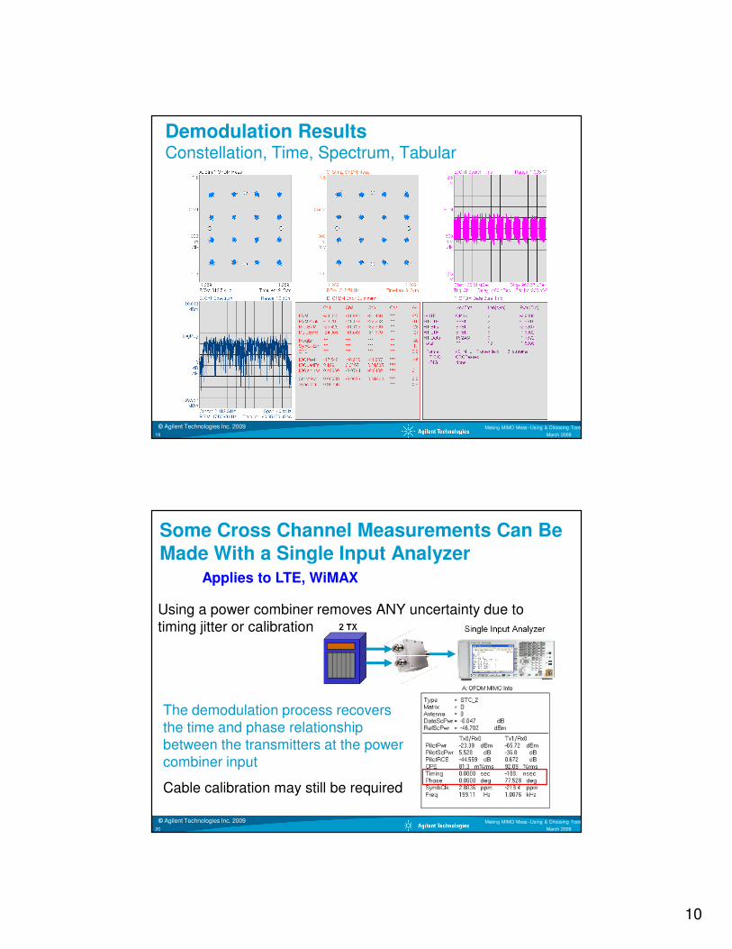
Demodulation ResultsConstellation, Time, Spectrum, Tabular
© Agilent Technologies Inc. 2009 Making MIMO Meas--Using & Choosing Tools
March 200920
Some Cross Channel Measurements Can Be
Made With a Single Input Analyzer
Using a power combiner removes ANY uncertainty due to timing jitter or calibration
The demodulation process recovers the time and phase relationship between the transmitters at the power combiner input
Cable calibration may still be required
Applies to LTE, WiMAX

11
© Agilent Technologies Inc. 2009 Making MIMO Meas--Using & Choosing Tools
March 200921
Symbol / Error table - Channel
• EVM parameters
• Freq / clock errors
• Common pilot error
• I/Q parameters
Symbol / Error table - Stream
• EVM parameters
• CPE
• Raw bits
Modulation Analysis: Tabular Results
© Agilent Technologies Inc. 2009 Making MIMO Meas--Using & Choosing Tools
March 200922
Signal Content: Tabular Results
Data Burst Info Table
Shows the modulation type,
length, power, and EVM of
data payload AND the
preamble
HT-SIG Info
Shows the contents in the High throughput Signal Symbol

12
© Agilent Technologies Inc. 2009 Making MIMO Meas--Using & Choosing Tools
March 200923
Demodulation Results
Measurements by Transmitter Detected Signal Content
© Agilent Technologies Inc. 2009 Making MIMO Meas--Using & Choosing Tools
March 200924
Orthogonal Modulation Analysis Results
Error Vector Spectrum
Shows the EVM detail by carrier
for every symbol time along with
the average EVM per carrier
(heavy line):
Error Vector Time
Shows the EVM detail by symbol time (EVM for every carrier during that symbol time) along with the average EVM per symbol time (heavy line)

13
© Agilent Technologies Inc. 2009 Making MIMO Meas--Using & Choosing Tools
March 200925
Frequency Response by Channel & Stream
Channel frequency responses
Shows the transfer functions (mag & phase) for each channel. Available for all data streams.
© Agilent Technologies Inc. 2009 Making MIMO Meas--Using & Choosing Tools
March 200926
Matrix condition number
Ratio of max/min singular values of a matrix. Value always ≥1 (or ≥ 0 dB). If this value is greater than signal SNR it is likely the MIMO separation of data streams will not work correctly.
MIMO Condition Number
What it is:
a) A way to see if your MIMO system is functioning correctly
b) A short term indication of the SNR you need to recover a MIMO signal
How you calculate it: Find the singular values of the channel matrix, and take the ratio of the highest / lowest

14
© Agilent Technologies Inc. 2009 Making MIMO Meas--Using & Choosing Tools
March 200927
4x4 Channel Matrix & Condition Number
© Agilent Technologies Inc. 2009 Making MIMO Meas--Using & Choosing Tools
March 200928
MIMO 4x4 Frequency Response802.11n Example: One Weak Channel

15
© Agilent Technologies Inc. 2009 Making MIMO Meas--Using & Choosing Tools
March 200929
Matrix Decoder & Crosstalk
Measurements Made Without Matrix Decoder
• Effects of crosstalk are included in measurement
• Crosstalk degrades EVM
• Error due to crosstalk can hide other errors
Measure Both Ways to Understand Error Contribution of Crosstalk
MatrixDecoder
OFDMDemod
ChanEstim.
Input Channel 1
Input Channel 2
Matrix A Analysis Stream
Matrix B Stream 1
Matrix B Stream 2
� Use Matrix Decoder
� Use Matrix Decoder
pilot-based EQ(decoder ON)
OFDM Meas Results
© Agilent Technologies Inc. 2009 Making MIMO Meas--Using & Choosing Tools
March 200930
Signal Analysis Solutions, Comparisons
Vector Signal Analysis Software
Spectrum/Signal Analyzers
Digital Oscilloscopes
Modular VXI
Design & Simulation Software
• Agilent ADS
• Matlab

16
© Agilent Technologies Inc. 2009 Making MIMO Meas--Using & Choosing Tools
March 200931
Dual RF Signal Analyzer MIMO Solution
Agilent MXA, EXA
• VSA software controls, coordinates both analyzers
• References locked, time-synchronized, LOs not shared
• True MIMO analysis, matrix decoding; phase-stable (over a packet), not phase coherent
• Signal/spectrum analyzers can be used independently
VSA software in signal analyzer or
external PC
Spatial multiplexing, demodulation
•10 MHz Freq ref.•Time sync
Tx0
Tx1
© Agilent Technologies Inc. 2009 Making MIMO Meas--Using & Choosing Tools
March 200932
Agilent Infiniium, InfiniiVision
Direct RF Input to 13GHz
2 - 4 Ch. VSA operates in oscilloscope or connected PC
Oscilloscope + VSA software use covered in detail inap-notes (see references)
Digitizing Oscilloscopes

17
© Agilent Technologies Inc. 2009 Making MIMO Meas--Using & Choosing Tools
March 200933
Digitizing OscilloscopesDriver & Integration, More Than Simple Data Transfer
Resample in Driver
• Decimation, resampling performed before measurement process
• Improves memory limitations, measurement speed
© Agilent Technologies Inc. 2009 Making MIMO Meas--Using & Choosing Tools
March 200934
Sampling Rate vs. Performance

18
© Agilent Technologies Inc. 2009 Making MIMO Meas--Using & Choosing Tools
March 200935
Oscilloscope Baseband Sampling Modes
Fs
Full rate mode
(Baseband)
Fs/2
Fs 2Fs
Maximize mode
(Signal discovery - wideband)
Minimize mode
(Signal discovery)
Fs 2Fs 3Fs 4Fs Scope sample mode
Meas. Speed
Signal acquire length*
EVM(noise floor)
Minimize(Max under-
sample)
Maximize(Least under-
sample)
User Rate(Any rate, nice for
Nyquist )
(Recom-mended)
Full Rate(No aliases)
User rate mode
(Nice for Nyquist)
Fs/2 Fs
© Agilent Technologies Inc. 2009 Making MIMO Meas--Using & Choosing Tools
March 200936
Alias Checking, Anti-Alias Filters
Alias Exposure Zone Checker Macro
• Measured & marked by automatically
• Any combination of CF span, sample rate
Anti-Alias Filters: Lowpass, Bandpass

19
© Agilent Technologies Inc. 2009 Making MIMO Meas--Using & Choosing Tools
March 200937
4 Channel Oscilloscopes, Agilent Examples
Model # Sample rate Freq Range Price
DSO 91304 40 GSa/s 13 GHz $ 115,000
DSO 90604 20 GSa/s 6 GHz $ 61,000
DSO 90404 20 GSa/s 4 GHz $ 48,500
DSO 90254 20 GSa/s 2.5 GHz $ 27,000
DSO 7104A 4 GSa/s 1 GHz $ 17,000
DSO 6104A 4 GSa/s 1 GHz $ 14,000
DSO 80000 Series 40 GSa/s 2-13 GHz
ExternalDownconversion,
Filtering}
© Agilent Technologies Inc. 2009 Making MIMO Meas--Using & Choosing Tools
March 200938
Comparison: Spectrum/Signal Analyzers
and Digital Oscilloscopes with VSA Software
Spectrum/Signal Analyzers
• Best dynamic range, EVM
• All traditional single-channel measurements
• Re-deploy analyzers as needed
• Measurement applications for distortion, phase noise
• Linked analyzers provide true MIMO analysis, demodulation
• Faster demodulation results
Digital Oscilloscopes
• Four simultaneous channels
• Full phase coherent analysis, best for channel modeling & beamforming
• Widest bandwidth
• Most cost-effective per channel for 3 - 4 channels
• Simpler physical configuration
• Very good EVM (at higher sample rates)

20
© Agilent Technologies Inc. 2009 Making MIMO Meas--Using & Choosing Tools
March 200939
VXI Modular 2 Channel Vector Signal
Analysis
89600 VSA Software
Shared ADC Sample Clock
Upgradable 1 Channel - 2 Channel
Selectable Channel Triggering
Common LO to 2.7GHz
• Phase coherent to 2.7 GHz
• Phase stable (over the course of a packet) to 6 GHz
© Agilent Technologies Inc. 2009 Making MIMO Meas--Using & Choosing Tools
March 200940
Multi-Input Alternative
Agilent N4010 for 802.11n
Measurement software gathers IQ information simultaneously from multiple receivers
Measurement software gets data sequentially from a multiplexing switch

21
© Agilent Technologies Inc. 2009 Making MIMO Meas--Using & Choosing Tools
March 200941
Measurements & Number of Inputs
© Agilent Technologies Inc. 2009 Making MIMO Meas--Using & Choosing Tools
March 200942
Signal Generation Solutions, Comparisons
Signal Generation Software
• Agilent Signal Studio, single channel & MIMO
RF Signal Generators
• Agilent ESG series, MXG series
MIMO Receiver Tester
• Agilent PXB
Design & Simulation Software
• Agilent ADS
• Matlab

22
© Agilent Technologies Inc. 2009 Making MIMO Meas--Using & Choosing Tools
March 200943
Linked RF Sources, MIMO-Capable SoftwareArbitrary Waveforms Generated by Signal Studio
Software Generates Arbitrary Waveforms for Baseband• Modulation, coding, frequency & power, signal generator coordination
Signal Generators Produce IF, RF Signals
• Can include impairments such as IQ errors, noise, phase noise
Some Fading• Fading Profiles repeated with the waveform
Agilent Signal Studio
© Agilent Technologies Inc. 2009 Making MIMO Meas--Using & Choosing Tools
March 200944
Agilent MXG Phase Coherence
This configuration has the flexibility to expand to 3 or 4 generators
Using separate generators, there is no constraint on RF frequency range
Timing synchronization is dealt with by instrument firmware
Reference Lock Provides Phase Stability (for a packet)
Shared LO Where Absolute Phase Needed (beamforming)

23
© Agilent Technologies Inc. 2009 Making MIMO Meas--Using & Choosing Tools
March 200945
N5106A PXB MIMO Receiver Tester:
Connectivity for Real-World Fading
The flexibility of the PXB is used to verify receiver performance throughout the design cycle, at baseband or RF
Page 45
Real-World RF
Analog I/Q- Direct from PXB- Connect to any DUT or RF
vector signal generator with analog I/Q inputs
RF
Digital I/Q
Signal OutputsSignal Inputs Signal Creation Tools
ESG or MXGPXBMXA(s)
N5102A
Coming up Later Today!
© Agilent Technologies Inc. 2009 Making MIMO Meas--Using & Choosing Tools
March 200946
Comparison: MIMO Receiver Tester and RF
Signal Generator(s) with ARBs
Signal Generators with ARBs
• Direct BB, IF, RF signal gen.
• Re-deploy sources as needed
• Produce fully coded signals
• Produce signals with IQ errors, noise
• Basic fading - fading profiles repeated with waveform (limited fade length not appropriate for slow fading)
MIMO Receiver Tester
• Four simultaneous channels
• Configurable channel correlation
• Signal input from Signal Studio, design/simulation programs, real-world RF capture
• Direct analog & digital BBIQ outputs, RF outputs through ESG, MXG signal generators
• Fast, precise, automated digital power calibration
• Fast, easy configuration changes
• Standards-compliant signals

24
© Agilent Technologies Inc. 2009 Making MIMO Meas--Using & Choosing Tools
March 200947
Test Types & Number of Sources
© Agilent Technologies Inc. 2009 Making MIMO Meas--Using & Choosing Tools
March 200948
Protocol & Conformance Test
Real-time LTE and WiMAX base station emulation for mobile development
Agilent E6651A
WiMAX
Anite SAT LTE Protocol Tester
with Development Toolset
built on the Agilent E6620A

25
© Agilent Technologies Inc. 2009 Making MIMO Meas--Using & Choosing Tools
March 200949
Additional Resources
www.agilent.com/find/mimo
Webcast: Ten Things You Should Know About MIMO
http://seminar2.techonline.com/s/agilent_Oct0808
Webcast: MIMO Channel Modelling and Emulation Test Challenges http://www.techonline.com/learning/webinar/210603655
MIMO WLAN PHY layer Operation and Measurement AN1509 http://cp.literature.agilent.com/litweb/pdf/5989-3443EN.pdf
Video: Single-channel measurements for WiMAX matrix A and B http://wireless.agilent.com/vcentral/viewvideo.aspx?vid=366
Webcast: WiMAX Wave 2 Testing - MIMO & STC http://www.techonline.com/learning/livewebinar/204203534
Vector Signal Analyzer & Oscilloscope Performance Guides:
• 6000 & 7000 series: Literature no. 5989-4523EN
• 80000 & 90000 series: Literature no. 5988-4096EN


![= N/#11N GJ= J77 ]](https://static.fdocuments.in/doc/165x107/5e8e5fc7b12190665911d57c/-n11n-gj-j77-.jpg)


