
Maintenance y - Material Handling Solutions | Hytrol … · · 2015-09-11TABLE OF CONTENTS...
36
Effective February 2014 (Supercedes December 2006) Bulletin #657 Installation and Maintenance Manual with Safety Information and Parts List RECOMMENDED SPARE PARTS HIGHLIGHTED IN GRAY Model ProSort SC1 & ProSort SC2 Manual de Instalación y Mantenimiento con Información sobre Seguridad y Lista de Refacciones LAS REFACCIONES RECOMENDADAS SE RESALTAN EN GRIS IMPORTANT! DO NOT DESTROY © COPYRIGHT 2009–HYTROL CONVEYOR CO., INC. ¡IMPORTANTE! NO DESTRUIR Hytrol Conveyor Co., Inc. Jonesboro, Arkansas PRESS OPTIMIZED FOR THE ENVIRONMENT (IMPRESIÓN OPTIMIZADA PARA PROTEGER EL MEDIO AMBIENTE)
Transcript of Maintenance y - Material Handling Solutions | Hytrol … · · 2015-09-11TABLE OF CONTENTS...

Effective February 2014(Supercedes December 2006)
Bulletin #657
Installationand
MaintenanceManual
with Safety Information
and Parts ListRECOMMENDED SPARE PARTS HIGHLIGHTED IN GRAY
Model ProSort SC1 & ProSort SC2
Manualde Instalación
yMantenimiento
con Información sobre Seguridad
y Lista de Refacciones LAS REFACCIONES RECOMENDADAS SE RESALTAN EN GRIS
IMPORTANT!DO NOT DESTROY
© COPYRIGHT 2009–HYTROL CONVEYOR CO., INC.
¡IMPORTANTE!NO DESTRUIR
Hytrol Conveyor Co., Inc.Jonesboro, Arkansas
PRESS OPTImIzED FOR THE ENVIRONmENT(ImpresIón OptImIzada para prOteger el medIO ambIente)
TABLE OF CONTENTS
INTRODUCTION Receiving and Uncrating . . . . . . . . . . . . . . . . . . . .2 How to Order Replacement Parts . . . . . . . . . . . . .2
SAFETY INFORmATION Installation Safety Precautions . . . . . . . . . . . . . . .3 Operation Safety Precautions . . . . . . . . . . . . . . . .3 maintenance . . . . . . . . . . . . . . . . . . . . . . . . . . . . .3 INSTALLATION Support Installation . . . . . . . . . . . . . . . . . . . . . . . .4 Conveyor Set-Up. . . . . . . . . . . . . . . . . . . . . . . . . .4 Electrical Equipment . . . . . . . . . . . . . . . . . . . . . . .5 Conveyor Start-Up. . . . . . . . . . . . . . . . . . . . . . . . .5 Lubrication . . . . . . . . . . . . . . . . . . . . . . . . . . . . . . .5 Belt Installation . . . . . . . . . . . . . . . . . . . . . . . . .5, 6 Belt Tracking . . . . . . . . . . . . . . . . . . . . . . . . . . .7, 8
mAINTENANCE Diverter Adjustment . . . . . . . . . . . . . . . . . . . . . . . .9 Diverter Wheel Alignment . . . . . . . . . . . . . . . . . . .9 Spur Installation/Placement. . . . . . . . . . . . . . . . .10 Trouble Shooting . . . . . . . . . . . . . . . . . . . . . . . . .11 maintenance Checklist . . . . . . . . . . . . . back cover
REPLACEmENT PARTS ProSort SC Parts Drawing. . . . . . . . . . . . . . . . . .12 ProSort SC Parts Drawing. . . . . . . . . . . . . . . . . .13 ProSort SC Parts Drawing. . . . . . . . . . . . . . . . . .14 ProSort SC Parts List . . . . . . . . . . . . . . . . . . . . .15 High Performance Shaft mounted Drive Parts Drawing & Parts List . . . . . . . . . . . . . . .16 Pneumatic Tensioner Parts Drawing & Parts List . . . . . . . . . . . . . . . . . . . . . . . . . . .17 Heavy Duty Shaft mounted Parts Drawing & Parts List . . . . . . . . . . . . . . . . . . . . . . . . . . .18 Tail Assembly Parts Drawing & Parts List. . . . . .19 Diverter Parts Drawing . . . . . . . . . . . . . . . . . . . .20 Diverter Parts Drawing & Parts List. . . . . . . . . . .21 Pneumatic Parts Drawing (Single Sided Diverter) . . . . . . . . . . . . . . . . . .22 Pneumatic Parts Drawing (Double Sided Diverter) . . . . . . . . . . . . . . . . .23 Powered Spur Parts Drawing . . . . . . . . . . . . . . .24 Powered Spur Parts List . . . . . . . . . . . . . . . . . . .25
Spanish Version . . . . . . . . . . . . . . . . . . 26
INTRODUCTIONThis manual provides guidelines and procedures for installing, oper-ating, and maintaining your conveyor. A complete parts list is pro-vided with recommended spare parts highlighted in gray. Important safety information is also provided throughout the manual. For safety to personnel and for proper operation of your conveyor, it is recommended that you read and follow the instructions provided in this manual.
• Receiving and Uncrating1. Check the number of items received against the bill of lading.2. Examine condition of equipment to determine if any damage
occurred during shipment.3. move all crates to area of installation.4. Remove crating and check for optional equipment that may be fastened to the conveyor. make sure these parts (or any foreign pieces) are removed.
• How to Order Replacement PartsIncluded in this manual are parts drawings with complete replace-ment parts lists. minor fasteners, such as nuts and bolts, are not included. When ordering replacement parts:1. Contact Dealer from whom conveyor was purchased or nearest
HYTROL Integration Partner.2. Give Conveyor model Number and Serial Number or HYTROL Factory Order Number.3. Give Part Number and complete description from Parts List.4. Give type of drive. Example—8” End Drive, 8” Center Drive, etc.5. If you are in a breakdown situation, tell us.
HYTROL Serial Number(Located near Drive on Powered models).
NOTE: If damage has occurred or freight is missing, Contact your Hytrol Integration Partner.
JONESBORO, ARKANSAS
ModelXX
Hytrol ConveyorCompany, Inc.
SERIAL # 123456
Model
2
SAFETY INFORMATION• InstallationGUARDS AND GUARDINGInterfacing of Equipment. When two or more pieces of equipment are interfaced, special attention shall be given to the interfaced area to insure the presence of adequate guarding and safety devices.Guarding Exceptions. Whenever conditions prevail that would require guarding under these standards, but such guarding would render the conveyor unusable, prominent warning means shall be provided in the area or on the equipment in lieu of guarding.Guarded by Location or Position. Where necessary for the protection of employees from hazards, all exposed moving machinery parts that present a hazard to employees at their work station shall be mechanically or electrically guarded, or guarded by location or position.
Remoteness from frequent presence of public or employed •personnel shall constitute guarding by location.When a conveyor passes over a walkway, roadway, or work •station, it is considered guarded solely by location or position if all moving parts are at least 8 ft. (2.44 m) above the floor or walking surface or are otherwise located so that the employee cannot inadvertently come in contact with hazardous moving parts.Although overhead conveyors may be guarded by location, spill •guards, pan guards, or equivalent shall be provided if the product may fall off the conveyor for any reason and if personnel would be endangered.
HEADROOmWhen conveyors are installed above exit passageways, aisles, •or corridors, there shall be provided a minimum clearance of 6 ft. 8 in. (2.032 m) measured vertically from the floor or walking surface to the lowest part of the conveyor or guards.Where system function will be impaired by providing the minimum •clearance of 6 ft. 8 in. (2.032 m) through an emergency clearance, alternate passageways shall be provided.It is permissible to allow passage under conveyors with less •than 6 ft. 8 in. (2.032 m) clearance from the floor for other than emergency exits if a suitable warning indicates low headroom.
• OperationA) Only trained employees shall be permitted to operate conveyors. Training shall include instruction in operation under normal conditions and emergency situations.
B) Where employee safety is dependent upon stopping and/or starting devices, they shall be kept free of obstructions to permit ready access.
C) The area around loading and unloading points shall be kept clear of obstructions which could endanger personnel.
D) No person shall ride the load-carrying element of a conveyor under any circumstances unless that person is specifically authorized by the owner or employer to do so. Under those circumstances, such employee shall only ride a conveyor which incorporates within its supporting structure platforms or control stations specifically designed for carrying personnel. Under no circumstances shall any person ride on any element of a vertical conveyor.
E) Personnel working on or near a conveyor shall be instructed as to the location and operation of pertinent stopping devices.
F) A conveyor shall be used to transport only material it is capable of handling safely.
G) Under no circumstances shall the safety characteristics of the conveyor be altered if such alterations would endanger personnel.
H) Routine inspections and preventive and corrective maintenance programs shall be conducted to insure that all safety features and
devices are retained and function properly.
I) Personnel should be alerted to the potential hazard of entanglement in conveyors caused by items such as long hair, loose clothing, and jewelry.
J) Conveyors shall not be maintained or serviced while in operation unless proper maintenance or service requires the conveyor to be in motion. In this case, personnel shall be made aware of the hazards and how the task may be safely accomplished.
K) Owners of conveyor should insure proper safety labels are affixed to the conveyor warning of particular hazards involved in operation of their conveyors.
• Maintenance All maintenance, including lubrication and adjustments, shall be •performed only by qualified and trained personnel.It is important that a maintenance program be established to •insure that all conveyor components are maintained in a condition which does not constitute a hazard to personnel.When a conveyor is stopped for maintenance purposes, starting •devices or powered accessories shall be locked or tagged out in accordance with a formalized procedure designed to protect all persons or groups involved with the conveyor against an unexpected start.Replace all safety devices and guards before starting equipment •for normal operation.Whenever practical, DO NOT lubricate conveyors while they are •in motion. Only trained personnel who are aware of the hazard of the conveyor in motion shall be allowed to lubricate.
Safety Guardsmaintain all guards and safety devices IN POSITION and IN SAFE REPAIR.
Safety LabelsIn an effort to reduce the possibility of injury to personnel working around HYTROL conveying equipment, safety labels are placed at various points on the equipment to alert them of potential hazards. Please check equipment and note all safety labels. make certain your personnel are alerted to and obey these warnings. See Safety manual for examples of warning labels.
CAUTION! Because of the many moving parts on the conveyor, all personnel in the area of the conveyor need to be warned
that the conveyor is about to be started.
CAUTION!Only trained personnel should track a conveyor belt which must be done
while conveyor is in operation. DO NOT attempt to track belt if conveyor is loaded.
REMEMBERDo not remove, reuse or modify material handling equipment for any
purpose other than it’s original intended use.
3
FLOW(FLUJO)
DRIVE SECTION(SECCION MOTRIZ)
ADJUST TO DESIRED ELEVATION(AJUSTE A LA ALTURA DESEADA)
DRIVE(UNIDAD MOTRIZ)
END DIVERTER(DESVIADOR DEL EXTREMO)
END DIVERTER(DESVIADOR DEL EXTREMO)
TAIL SECTION(SECCION DE RETORNO)
INTERMEDIATE SECTION(SECCION INTERMEDIA)
DIVERT SECTION(SECCION DE DESVIACIÓN)
INTERMEDIATE DIVERTER(DESVIADOR-INTERMEDIO)
"MATCH-MARK" NUMBERS(ETIQUETAS DE SECUENCIA DE ARMADO)
MARKCONVEYOR F.0.#ITEM TO
HYTROL CONVEYOR CO. INC.JONESBORO, AR
A
1212345
MARKCONVEYOR F.0.#ITEM TO
HYTROL CONVEYOR CO. INC.JONESBORO, AR
A
1 212345NOTE: ALLOW FOR BELT THICKNESS WHEN ADJUSTING SUPPORTS
(NOTA: DEJE ESPACIO SUFICIENTE PARA EL ESPESOR DE LA BANDA CUANDO AJUSTE LOS SOPORTES)
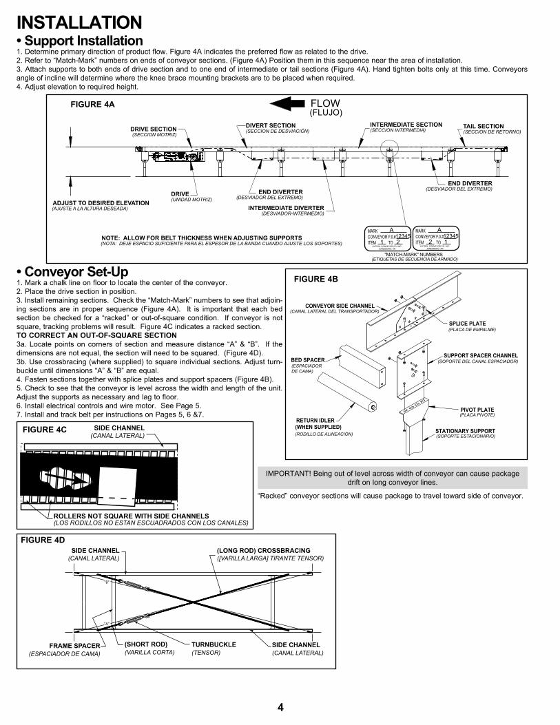
INSTALLATION• Support Installation1. Determine primary direction of product flow. Figure 4A indicates the preferred flow as related to the drive.2. Refer to “match-mark” numbers on ends of conveyor sections. (Figure 4A) Position them in this sequence near the area of installation.3. Attach supports to both ends of drive section and to one end of intermediate or tail sections (Figure 4A). Hand tighten bolts only at this time. Conveyors angle of incline will determine where the knee brace mounting brackets are to be placed when required.4. Adjust elevation to required height.
FIGURE 4A
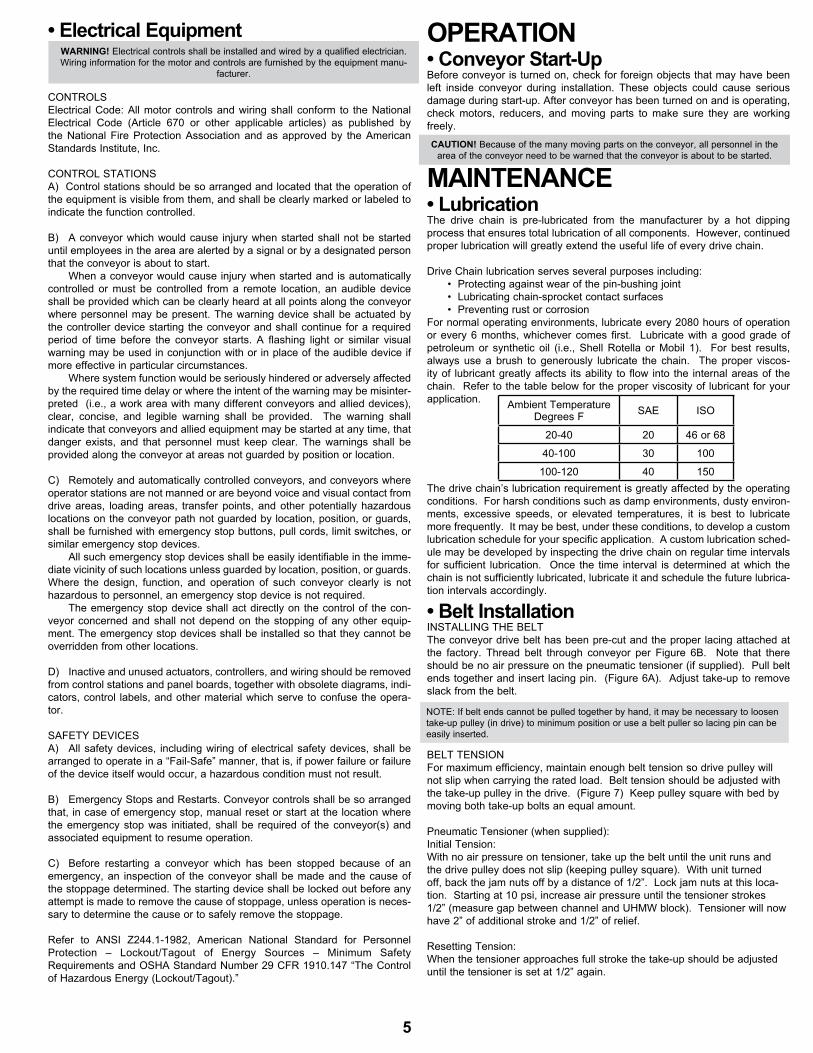
• Conveyor Set-Up1. mark a chalk line on floor to locate the center of the conveyor.2. Place the drive section in position.3. Install remaining sections. Check the “match-mark” numbers to see that adjoin-ing sections are in proper sequence (Figure 4A). It is important that each bed section be checked for a “racked” or out-of-square condition. If conveyor is not square, tracking problems will result. Figure 4C indicates a racked section.TO CORRECT AN OUT-OF-SQUARE SECTION3a. Locate points on corners of section and measure distance “A” & “B”. If the dimensions are not equal, the section will need to be squared. (Figure 4D).3b. Use crossbracing (where supplied) to square individual sections. Adjust turn-buckle until dimensions “A” & “B” are equal.4. Fasten sections together with splice plates and support spacers (Figure 4B).5. Check to see that the conveyor is level across the width and length of the unit. Adjust the supports as necessary and lag to floor. 6. Install electrical controls and wire motor. See Page 5.7. Install and track belt per instructions on Pages 5, 6 &7.
(WHEN SUPPLIED)RETURN IDLER
SUPPORT SPACER CHANNEL
CONVEYOR SIDE CHANNEL
PIVOT PLATE
STATIONARY SUPPORT
SPLICE PLATE(PLACA DE EMPALME)
(SOPORTE DEL CANAL ESPACIADOR)
(RODILLO DE ALINEACIÓN)
BED SPACER(ESPACIADORDE CAMA)
(PLACA PIVOTE)
(SOPORTE ESTACIONARIO)
(CANAL LATERAL DEL TRANSPORTADOR)
ImPORTANT! Being out of level across width of conveyor can cause package drift on long conveyor lines.
SIDE CHANNEL(CANAL LATERAL)
ROLLERS NOT SQUARE WITH SIDE CHANNELS(LOS RODILLOS NO ESTAN ESCUADRADOS CON LOS CANALES)
“Racked” conveyor sections will cause package to travel toward side of conveyor.
"A"
"B"
SIDE CHANNEL(CANAL LATERAL)
(SHORT ROD)(VARILLA CORTA)
FRAME SPACER(ESPACIADOR DE CAMA)
TURNBUCKLE(TENSOR)
SIDE CHANNEL(CANAL LATERAL)
(LONG ROD) CROSSBRACING([VARILLA LARGA] TIRANTE TENSOR)
FIGURE 4B
FIGURE 4C
FIGURE 4D
4
• Electrical Equipment
CONTROLSElectrical Code: All motor controls and wiring shall conform to the National Electrical Code (Article 670 or other applicable articles) as published by the National Fire Protection Association and as approved by the American Standards Institute, Inc.
CONTROL STATIONSA) Control stations should be so arranged and located that the operation of the equipment is visible from them, and shall be clearly marked or labeled to indicate the function controlled.
B) A conveyor which would cause injury when started shall not be started until employees in the area are alerted by a signal or by a designated person that the conveyor is about to start. When a conveyor would cause injury when started and is automatically controlled or must be controlled from a remote location, an audible device shall be provided which can be clearly heard at all points along the conveyor where personnel may be present. The warning device shall be actuated by the controller device starting the conveyor and shall continue for a required period of time before the conveyor starts. A flashing light or similar visual warning may be used in conjunction with or in place of the audible device if more effective in particular circumstances. Where system function would be seriously hindered or adversely affected by the required time delay or where the intent of the warning may be misinter-preted (i.e., a work area with many different conveyors and allied devices), clear, concise, and legible warning shall be provided. The warning shall indicate that conveyors and allied equipment may be started at any time, that danger exists, and that personnel must keep clear. The warnings shall be provided along the conveyor at areas not guarded by position or location.
C) Remotely and automatically controlled conveyors, and conveyors where operator stations are not manned or are beyond voice and visual contact from drive areas, loading areas, transfer points, and other potentially hazardous locations on the conveyor path not guarded by location, position, or guards, shall be furnished with emergency stop buttons, pull cords, limit switches, or similar emergency stop devices. All such emergency stop devices shall be easily identifiable in the imme-diate vicinity of such locations unless guarded by location, position, or guards. Where the design, function, and operation of such conveyor clearly is not hazardous to personnel, an emergency stop device is not required. The emergency stop device shall act directly on the control of the con-veyor concerned and shall not depend on the stopping of any other equip-ment. The emergency stop devices shall be installed so that they cannot be overridden from other locations.
D) Inactive and unused actuators, controllers, and wiring should be removed from control stations and panel boards, together with obsolete diagrams, indi-cators, control labels, and other material which serve to confuse the opera-tor.
SAFETY DEVICESA) All safety devices, including wiring of electrical safety devices, shall be arranged to operate in a “Fail-Safe” manner, that is, if power failure or failure of the device itself would occur, a hazardous condition must not result.
B) Emergency Stops and Restarts. Conveyor controls shall be so arranged that, in case of emergency stop, manual reset or start at the location where the emergency stop was initiated, shall be required of the conveyor(s) and associated equipment to resume operation.
C) Before restarting a conveyor which has been stopped because of an emergency, an inspection of the conveyor shall be made and the cause of the stoppage determined. The starting device shall be locked out before any attempt is made to remove the cause of stoppage, unless operation is neces-sary to determine the cause or to safely remove the stoppage.
Refer to ANSI z244.1-1982, American National Standard for Personnel Protection – Lockout/Tagout of Energy Sources – minimum Safety Requirements and OSHA Standard Number 29 CFR 1910.147 “The Control of Hazardous Energy (Lockout/Tagout).”
OPERATION• Conveyor Start-UpBefore conveyor is turned on, check for foreign objects that may have been left inside conveyor during installation. These objects could cause serious damage during start-up. After conveyor has been turned on and is operating, check motors, reducers, and moving parts to make sure they are working freely.
MAINTENANCE• LubricationThe drive chain is pre-lubricated from the manufacturer by a hot dipping process that ensures total lubrication of all components. However, continued proper lubrication will greatly extend the useful life of every drive chain. Drive Chain lubrication serves several purposes including: • Protecting against wear of the pin-bushing joint • Lubricating chain-sprocket contact surfaces • Preventing rust or corrosionFor normal operating environments, lubricate every 2080 hours of operation or every 6 months, whichever comes first. Lubricate with a good grade of petroleum or synthetic oil (i.e., Shell Rotella or mobil 1). For best results, always use a brush to generously lubricate the chain. The proper viscos-ity of lubricant greatly affects its ability to flow into the internal areas of the chain. Refer to the table below for the proper viscosity of lubricant for your application.
The drive chain’s lubrication requirement is greatly affected by the operating conditions. For harsh conditions such as damp environments, dusty environ-ments, excessive speeds, or elevated temperatures, it is best to lubricate more frequently. It may be best, under these conditions, to develop a custom lubrication schedule for your specific application. A custom lubrication sched-ule may be developed by inspecting the drive chain on regular time intervals for sufficient lubrication. Once the time interval is determined at which the chain is not sufficiently lubricated, lubricate it and schedule the future lubrica-tion intervals accordingly.
• Belt InstallationINSTALLING THE BELTThe conveyor drive belt has been pre-cut and the proper lacing attached at the factory. Thread belt through conveyor per Figure 6B. Note that there should be no air pressure on the pneumatic tensioner (if supplied). Pull belt ends together and insert lacing pin. (Figure 6A). Adjust take-up to remove slack from the belt.
BELT TENSIONFor maximum efficiency, maintain enough belt tension so drive pulley will not slip when carrying the rated load. Belt tension should be adjusted with the take-up pulley in the drive. (Figure 7) Keep pulley square with bed by moving both take-up bolts an equal amount.
Pneumatic Tensioner (when supplied):Initial Tension:With no air pressure on tensioner, take up the belt until the unit runs and the drive pulley does not slip (keeping pulley square). With unit turned off, back the jam nuts off by a distance of 1/2”. Lock jam nuts at this loca-tion. Starting at 10 psi, increase air pressure until the tensioner strokes 1/2” (measure gap between channel and UHmW block). Tensioner will now have 2” of additional stroke and 1/2” of relief.
Resetting Tension: When the tensioner approaches full stroke the take-up should be adjusted until the tensioner is set at 1/2” again.
WARNING! Electrical controls shall be installed and wired by a qualified electrician. Wiring information for the motor and controls are furnished by the equipment manu-
facturer.
CAUTION! Because of the many moving parts on the conveyor, all personnel in the area of the conveyor need to be warned that the conveyor is about to be started.
Ambient TemperatureDegrees F SAE ISO
20-40 20 46 or 68
40-100 30 100
100-120 40 150
NOTE: If belt ends cannot be pulled together by hand, it may be necessary to loosen take-up pulley (in drive) to minimum position or use a belt puller so lacing pin can be easily inserted.
5

CAUTION! Excessive slippage will reduce belt life and damage drive pulley lagging. Never apply more tension than is needed. Over-tension will cause extra wear to belt and bearings and will require extra power
from drive.
TAIL ASSEMBLY
FLOW
DRIvE PULLEY
HIGH PERFORMANCE DRIvE
INTERMEDIATE DIvERTER
DIvERTERINFEED END
DIvERTERDISCHARGE ENDRETURN BELT
RETURN BELT
RETURN BELT
TOP BELT
TOP BELT
TOP BELT
TAIL PULLEY(pOlea de retOrnO)
SNUB IDLER(rOdIllO dealIneaCIOn)
(banda sUperIOr)
(banda de retOrnO)
(banda de retOrnO)
(banda de retOrnO)
(banda sUperIOr)
(banda sUperIOr)
(desVIadOr del eXtremOde desCarga)
(desVIadOr del eXtremOde alImentaCIón)
(mOntaJe del eXtremO de retOrnO)(UnIdad mOtrIz de altO desempeÑO)
(desVIadOr IntermedIO)
TAIL PULLEY(pOlea deretOrnO)
BELT(banda)
TAKE UP PULLEY(pOlea de tensIOn)
(pOlea mOtrIz)
(FlUJO)
HEAvY DUTY DRIvE(UnIdad mOtrIz para trabaJO pesadO)
PNEUMATIC TAKE UP(WHEN SUPPLIED)
(tensIOnadOr neUmÁtICO) [CUandO es sUmInIstradO]
SNUB IDLER(rOdIllO dealIneaCIOn)
FLOW
SUPPORT ANGLE
BELT(BANDA)
(ANGULO DE SOPORTE)
(FLUJO)
SIDE “Y”(LADO “Y”)
SIDE “X”(LADO “X”)
B
D
B BBA
C
BELT LACING
BELT
LACING PIN
(ENLACE DE BANDA)
(BANDA)
(PASADOR DE ENLACE)
• Belt Installation FIGURE 6A
FIGURE 6B
FIGURE 6C
6
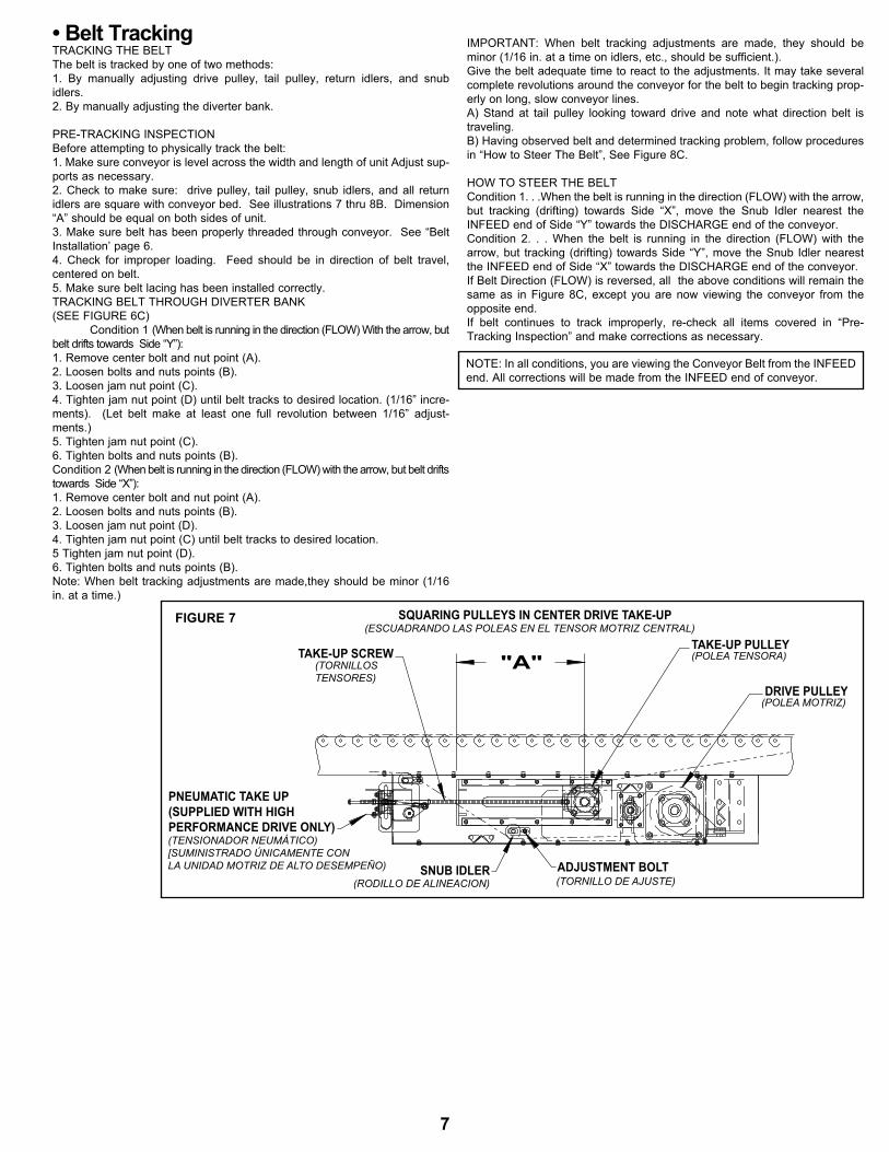
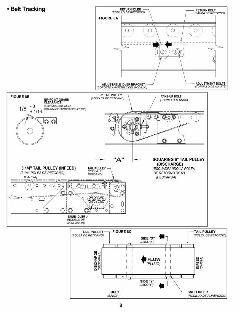
• Belt Tracking TRACKING THE BELTThe belt is tracked by one of two methods:1. By manually adjusting drive pulley, tail pulley, return idlers, and snub idlers.2. By manually adjusting the diverter bank. PRE-TRACKING INSPECTIONBefore attempting to physically track the belt:1. make sure conveyor is level across the width and length of unit Adjust sup-ports as necessary.2. Check to make sure: drive pulley, tail pulley, snub idlers, and all return idlers are square with conveyor bed. See illustrations 7 thru 8B. Dimension “A” should be equal on both sides of unit.3. make sure belt has been properly threaded through conveyor. See “Belt Installation’ page 6.4. Check for improper loading. Feed should be in direction of belt travel, centered on belt.5. make sure belt lacing has been installed correctly.TRACKING BELT THROUGH DIVERTER BANK (SEE FIGURE 6C) Condition 1 (When belt is running in the direction (FLOW) With the arrow, but belt drifts towards Side “Y”): 1. Remove center bolt and nut point (A). 2. Loosen bolts and nuts points (B). 3. Loosen jam nut point (C). 4. Tighten jam nut point (D) until belt tracks to desired location. (1/16” incre-ments). (Let belt make at least one full revolution between 1/16” adjust-ments.)5. Tighten jam nut point (C).6. Tighten bolts and nuts points (B).Condition 2 (When belt is running in the direction (FLOW) with the arrow, but belt drifts towards Side “X”):1. Remove center bolt and nut point (A). 2. Loosen bolts and nuts points (B). 3. Loosen jam nut point (D). 4. Tighten jam nut point (C) until belt tracks to desired location. 5 Tighten jam nut point (D). 6. Tighten bolts and nuts points (B).Note: When belt tracking adjustments are made,they should be minor (1/16 in. at a time.)
ImPORTANT: When belt tracking adjustments are made, they should be minor (1/16 in. at a time on idlers, etc., should be sufficient.).Give the belt adequate time to react to the adjustments. It may take several complete revolutions around the conveyor for the belt to begin tracking prop-erly on long, slow conveyor lines.A) Stand at tail pulley looking toward drive and note what direction belt is traveling.B) Having observed belt and determined tracking problem, follow procedures in “How to Steer The Belt”, See Figure 8C.
HOW TO STEER THE BELTCondition 1. . .When the belt is running in the direction (FLOW) with the arrow, but tracking (drifting) towards Side “X”, move the Snub Idler nearest the INFEED end of Side “Y” towards the DISCHARGE end of the conveyor.Condition 2. . . When the belt is running in the direction (FLOW) with the arrow, but tracking (drifting) towards Side “Y”, move the Snub Idler nearest the INFEED end of Side “X” towards the DISCHARGE end of the conveyor.If Belt Direction (FLOW) is reversed, all the above conditions will remain the same as in Figure 8C, except you are now viewing the conveyor from the opposite end.If belt continues to track improperly, re-check all items covered in “Pre-Tracking Inspection” and make corrections as necessary.
TAKE-UP SCREWTAKE-UP PULLEY
DRIvE PULLEY
SNUB IDLER ADJUSTMENT BOLT
SQUARINg PULLEYS IN CENTER DRIvE TAKE-UP
(pOlea tensOra)
(esCUadrandO las pOleas en el tensOr mOtrIz Central)
(tOrnIllOstensOres)
(pOlea mOtrIz)
(rOdIllO de alIneaCIOn) (tOrnIllO de aJUste)
"A"
PNEUMATIC TAKE UP(SUPPLIED WITH HIGHPERFORMANCE DRIvE ONLY)(tensIOnadOr neUmÁtICO)[sUmInIstradO ÚnICamente COn la UnIdad mOtrIz de altO desempeÑO)
NOTE: In all conditions, you are viewing the Conveyor Belt from the INFEED end. All corrections will be made from the INFEED end of conveyor.
FIGURE 7
7
RETURN IDLER(RODILLO DE RETORNO)
RETURN BELT(BANDA DE RETORNO)
ADJUSTMENT BOLTS(TORNILLO DE AJUSTE)
ADJUSTABLE IDLER BRACKET(SOPORTE AJUSTABLE DEL RODILLO)
+ 1/16- 01/8
"A"
(3 1/4" pOlea de retOrnO) [Carga]
3 1/4" TAIL PULLEY (INFEED)
CLEARANCE(espaCIO lIbre de la gUarda de pUntOs eXpUestOs)
NIP POINT GUARD6" TAIL PULLEY TAKE-UP BOLT
(DISCHARGE)(esCUadrandO la pOlea de retOrnO de 6") [desCarga]
SQUARINg 6" TAIL PULLEY
(tOrnIllO tensOr)(6" pOlea de retOrnO)
TAIL PULLEY(pOlea deretOrnO)
SNUB IDLER(rOdIllO dealIneaCIOn)
• Belt Tracking
FLOW
SIDE "X"
TAIL PULLEY
BELT SNUB IDLER
INFE
ED
DIS
CH
AR
GE
TAIL PULLEY
SIDE "Y"
(RODILLO DE ALINEACION)
(POLEA DE RETORNO)(POLEA DE RETORNO)
(LADO"Y")
(BANDA)
(LADO"X")
(FLUJO)
(CA
RG
A)
(DE
SC
AR
GA
)
FIGURE 8A
FIGURE 8B
FIGURE 8C
8
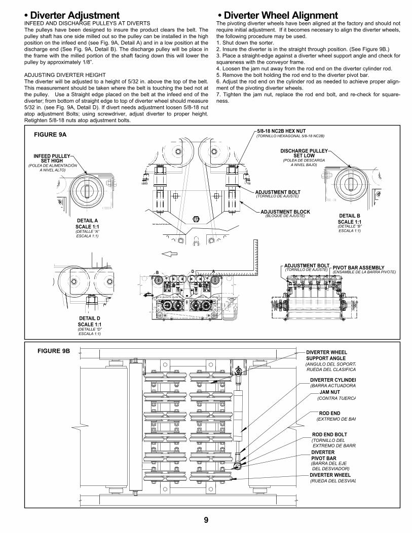
• Diverter AdjustmentINFEED AND DISCHARGE PULLEYS AT DIVERTSThe pulleys have been designed to insure the product clears the belt. The pulley shaft has one side milled out so the pulley can be installed in the high position on the infeed end (see Fig. 9A, Detail A) and in a low position at the discharge end (See Fig. 9A, Detail B). The discharge pulley will be place in the frame with the milled portion of the shaft facing down this will lower the pulley by approximately 1/8”.
ADJUSTING DIVERTER HEIGHTThe diverter will be adjusted to a height of 5/32 in. above the top of the belt. This measurement should be taken where the belt is touching the bed not at the pulley. Use a Straight edge placed on the belt at the infeed end of the diverter; from bottom of straight edge to top of diverter wheel should measure 5/32 in. (see Fig. 9A, Detail D). If divert needs adjustment loosen 5/8-18 nut atop adjustment Bolts; using screwdriver, adjust diverter to proper height. Retighten 5/8-18 nuts atop adjustment bolts.
• Diverter Wheel AlignmentThe pivoting diverter wheels have been aligned at the factory and should not require initial adjustment. If it becomes necesary to align the diverter wheels, the following procedure may be used.1. Shut down the sorter.2. Insure the diverter is in the straight through position. (See Figure 9B.)3. Place a straight-edge against a diverter wheel support angle and check for squareness with the conveyor frame.4. Loosen the jam nut away from the rod end on the diverter cylinder rod.5. Remove the bolt holding the rod end to the diverter pivot bar.6. Adjust the rod end on the cylinder rod as needed to achieve proper align-ment of the pivoting diverter wheels.7. Tighten the jam nut, replace the rod end bolt, and re-check for square-ness.
DETAIL ASCALE 1:1
5/8-18 NC2B HEX NUT
INFEED PULLEYSET HIGH
PIvOT BAR ASSEMBLYADJUSTMENT BOLT
(pOlea de alImentaCIóna nIVel altO)
(tOrnIllO HeXagOnal 5/8-18 nC2b)
(tOrnIllO de aJUste) (ensamble de la barra pIVOte)
(detalle “a”esCala 1:1)
ADJUSTMENT BOLT(tOrnIllO de aJUste)
ADJUSTMENT BLOCK(blOQUe de aJUste) DETAIL B
SCALE 1:1(detalle “b”esCala 1:1)
DISCHARGE PULLEYSET LOW
(pOlea de desCargaa nIVel baJO)
DETAIL DSCALE 1:1(detalle “d”esCala 1:1)
B D A
DIVERTER WHEEL
ROD END
JAM NUT
DIVERTER CYLINDER
PIVOT BARDIVERTER
ROD END BOLT
SUPPORT ANGLEDIVERTER WHEEL
(ANGULO DEL SOPORTE DE LA RUEDA DEL CLASIFICADOR)
(BARRA ACTUADORA)
(CONTRA TUERCA)
(EXTREMO DE BARRA)
(TORNILLO DEL EXTREMO DE BARRA)
(BARRA DEL EJE DEL DESVIADOR)
(RUEDA DEL DESVIADOR)
FIGURE 9A
FIGURE 9B
9
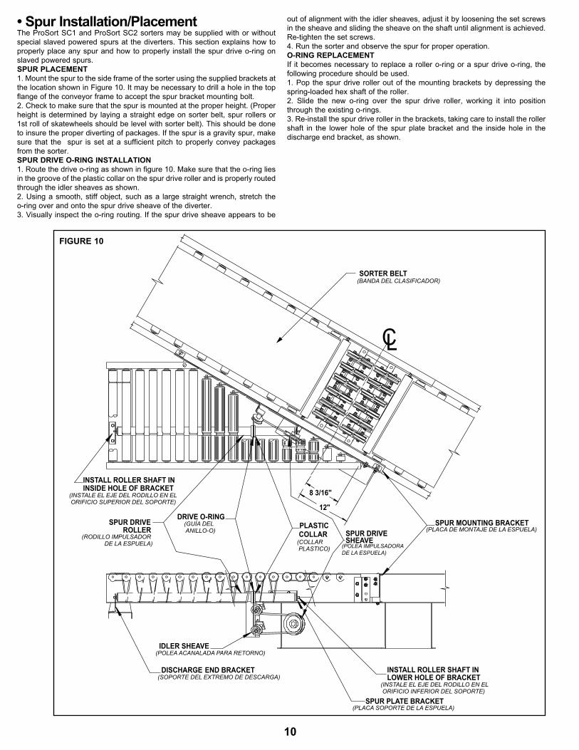
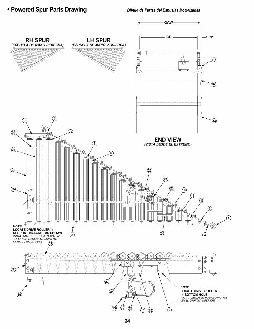
• Spur Installation/PlacementThe ProSort SC1 and ProSort SC2 sorters may be supplied with or without special slaved powered spurs at the diverters. This section explains how to properly place any spur and how to properly install the spur drive o-ring on slaved powered spurs.SPUR PLACEMENT1. mount the spur to the side frame of the sorter using the supplied brackets at the location shown in Figure 10. It may be necessary to drill a hole in the top flange of the conveyor frame to accept the spur bracket mounting bolt.2. Check to make sure that the spur is mounted at the proper height. (Proper height is determined by laying a straight edge on sorter belt, spur rollers or 1st roll of skatewheels should be level with sorter belt). This should be done to insure the proper diverting of packages. If the spur is a gravity spur, make sure that the spur is set at a sufficient pitch to properly convey packages from the sorter. SPUR DRIvE O-RINg INSTALLATION1. Route the drive o-ring as shown in figure 10. make sure that the o-ring lies in the groove of the plastic collar on the spur drive roller and is properly routed through the idler sheaves as shown.2. Using a smooth, stiff object, such as a large straight wrench, stretch the o-ring over and onto the spur drive sheave of the diverter.3. Visually inspect the o-ring routing. If the spur drive sheave appears to be
out of alignment with the idler sheaves, adjust it by loosening the set screws in the sheave and sliding the sheave on the shaft until alignment is achieved. Re-tighten the set screws.4. Run the sorter and observe the spur for proper operation.O-RINg REPLACEMENTIf it becomes necessary to replace a roller o-ring or a spur drive o-ring, the following procedure should be used.1. Pop the spur drive roller out of the mounting brackets by depressing the spring-loaded hex shaft of the roller.2. Slide the new o-ring over the spur drive roller, working it into position through the existing o-rings.3. Re-install the spur drive roller in the brackets, taking care to install the roller shaft in the lower hole of the spur plate bracket and the inside hole in the discharge end bracket, as shown.
12"
8 3/16"
END BRACKETDISCHARGE
SPUR PLATE BRACKET
INSIDE HOLE OF BRACKETINSTALL ROLLER SHAFT IN
LOWER HOLE OF BRACKETINSTALL ROLLER SHAFT IN
IDLER SHEAvE
SHEAvESPUR DRIvECOLLAR
PLASTICROLLERSPUR DRIvE
DRIvE O-RINgSPUR MOUNTING BRACKET
C
(plaCa de mOntaJe de la espUela)
(pOlea ImpUlsadOra de la espUela)
(gUÍa del anIllO-O)
(Instale el eJe del rOdIllO en el OrIFICIO sUperIOr del sOpOrte)
(rOdIllO ImpUlsadOr de la espUela)
(pOlea aCanalada para retOrnO)
(sOpOrte del eXtremO de desCarga)(Instale el eJe del rOdIllO en el OrIFICIO InFerIOr del sOpOrte)
(plaCa sOpOrte de la espUela)
(COllar plastICO)
L
SORTER BELT(banda del ClasIFICadOr)
FIGURE 10
10

TROUBLE SHOOTING DRIVES
TROUBLE CAUSE SOLUTION
Conveyor will not start or motor quits frequently.
1) motor is overloaded. 2) motor is drawing too much current.
1) Check for overloading of conveyor. 2) Check heater or circuit breaker and change if necessary
Drive belt wears exces-sively.
1) Belt is too loose. 1) Tighten belt.2) Check pneumatic tensioner. (see below)
Loud popping or grind-ing noise.
1) Defective bearing. 1) Replace bearing.
motor or reducer over-heating.
1) Conveyor is overloaded. 2) Low voltage to motor. 3) Low lubricant level in reducer.
1) Check capacity of conveyor and reduce load to recommended level. 2) Have electrician check and correct as necessary. 3) Relubricate per manufacturer’s recommendations.
Belt does not move, but drive runs.
1) Conveyor is overloaded.2) Belt is too loose.3) Lagging on drive pulley is worn
1) Check capacity of conveyor and reduce load to recommended level.2) Tighten belt.3) Check pneumatic tensioner. (see below)4) Replace drive pulley and tighten belt.
Diverter wheels not turn-ing under loaded condi-tions.
1) Conveyor is overloaded.2) Package flow obstructed by guard rail or other
object.
1) Check capacity of conveyor and reduce load to recommended level.2) Clear obstruction.
Inoperative diverter. 1) No air pressure to cylinder.2) Air solenoid defective.
1) Check for restricted or broken air line.2) Replace air solenoid.
Inoperative pneumatic tensioner.
1) No air pressure to air bag.2) Tensioner at full stroke.
1) Check for restricted or broken air line.2) Resent tensioner. (see belt tension)
Product not diverting. 1) Divert height out of adjustment.2) Out of spec product.
1) Adjust divert to proper height.2) Remove or put product in tote.
Product bounces at diverts.
1) Divert height out of adjustment.2) Out of spec product.
1) Adjust divert to proper height.2) Remove or put product in tote.
TROUBLE SHOOTING DRIVE BELT TRACKING
TROUBLE CAUSE SOLUTION
Belt creeps to one side at tail pulley.
1) Return idler, or snub idler near tail pulley not prop-erly aligned or square with bed.
1) Adjust as necessary. See “Belt Tracking” in this manual for details.
Entire belt creeps to one side.
1) Conveyor not straight.2) Conveyor not level.3) material build-up on rollers, pulleys, or idlers.
1) Re-align bed sections as necessary.2) Correct as necessary.3) Remove residue and install belt cleaners or scrapers if possible.
• Trouble Shooting
11

• Model ProSort SC Parts Drawing Dibujo de Partes del Modelo ProSort SC
22
21
10 1516
17
9 8 67
13
14
24
26
2511
20
1
SEE PAGE 17 FOR PNEUMATICTENSIONER (SUPPLIED ON HIGHPERFORMANCE DRIvE ONLY)(Vea la pagIna 17 para el tensIOnadOr neUmatICO)[prOVeIdO sOlamente COnla UnIdad mOtrIz de altOdesempeÑO]
SEE PAGE 16 FOR HIGH PERFORMANCE SHAFT MOUNTED CENTER DRIvE AND PAGE 18 FOR HEAvY DUTY SHAFT MOUNTED CENTER DRIvE(Vea la pagIna 16 para el eJe de altO desempeÑO mOntadO en UnIdad mOtrIz Central Y la pagIna 18 para el eJe de trabaJO pesadO mOntadO en UnIdad mOtrIz Central .)
"A"
"A"
SECTION "A-A"(seCCIOn "a-a")
SEE PAGE 19 FOR TAILS (Vea la pagIna 19 para lOs eXtremOs de retOrnO)
2
OAWBR1 1/2"
6 1/2"
10 1/4"
12
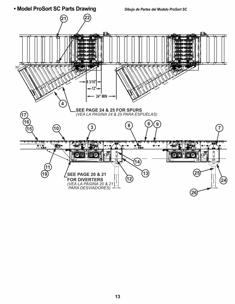
• Model ProSort SC Parts Drawing Dibujo de Partes del Modelo ProSort SC
21 22
4
1516
17
10 3 8 6 97
242513
12
11SEE PAGE 20 & 21FOR DIVERTERS(VEA LA PAGINA 20 & 21 PARA DESVIADORES)
19
26
SEE PAGE 24 & 25 FOR SPURS(VEA LA PAGINA 24 & 25 PARA ESPUELAS)
8 3/16"12"
24" MIN
30°
14
13
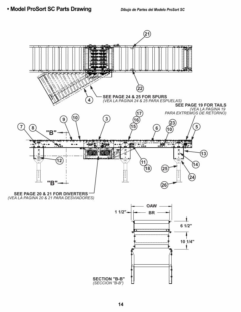
22
21
22
SEE PAGE 24 & 25 FOR SPURS(VEA LA PAGINA 24 & 25 PARA ESPUELAS)
SEE PAGE 19 FOR TAILS(VEA LA PAGINA 19
PARA EXTREMOS DE RETORNO)
4
109
873
1516
17
6 5
13
14
2426
2511
18
SEE PAGE 20 & 21 FOR DIVERTERS(VEA LA PAGINA 20 & 21 PARA DESVIADORES)
"B"
"B"
SECTION "B-B"(SECCION "B-B")
OAWBR1 1/2"
6 1/2"
10 1/4"
12
1023
• Model ProSort SC Parts Drawing Dibujo de Partes del Modelo ProSort SC
14
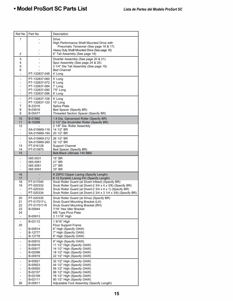
• Model ProSort SC Parts List Lista de Partes del Modelo ProSort SC
Ref No Part No Description
1
2
--
--
DriveHigh Performance Shaft mounted Drive with Pneumatic Tensioner (See page 16 & 17)Heavy Duty Shaft mounted Drive (See page 18)6” Tail Assembly (See page 19)
3456-
----
PT-132837-048
Diverter Assembly (See page 20 & 21)Spur Assembly (See page 24 & 25)3 1/4” Dia Tail Assembly (See page 19)Bed Channel4’ Long
-----
PT-132837-060PT-132837-072PT-132837-084PT-132837-090PT-132837-096
5’ Long6’ Long7’ Long7’6” Long8’ Long
--789
PT-132837-108PT-132837-120B-23316B-03916B-05477
9’ Long10’ LongSplice PlateBed Spacer (Specify BR)Threaded Section Spacer (Specify BR)
101112--
B-01982B-15299
-SA-015669-116SA-015669-164
1.9 Dia. Galvanized Roller (Specify BR)2 1/2” Dia Snub/Idler Roller (Specify BR)2 1/8” Dia. Roller Assembly14 1/2” BR20 1/2” BR
--
131415
SA-015669-212SA-015669-260PT-016128PT-013975
-
26 1/2” BR32 1/2” BRSupport Channel Bed Spacer (Specify BR)Belt-Black Ultimate 140 BBS
----
065.5031065.5061065.5081065.5091
15” BR21” BR27” BR33” BR
16171819--
--
PT-017045PT-020332PT-020333PT-020334
# 2SPG Clipper Lacing (Specify Length)# 13 Duralink Lacing Pin (Specify Length)Snub Roller Guard (at Divert Infeed) (Specify BR)Snub Roller Guard (at Divert-2 3/4 x 4 x 3/8) (Specify BR)Snub Roller Guard (at Divert-2 3/4 x 4 x 1) (Specify BR)Snub Roller Guard (at Divert-2 3/4 x 3 1/4 x 3/8) (Specify BR)
2021222324-
PT-020335PT-017017-LPT-017017-RB-00944
-B-00913
Snub Roller Guard (at Drive) (Specify BR)Snub Guard mounting Bracket (LH)Snub Guard mounting Bracket (RH)7/16” Hex Idler BracketmS Type Pivot Plate3 11/16” High
-25---
B-02112-
B-00914B-12777B-12778
1 9/16” HighFloor Support Frame6” High (Specify OAW)7” High (Specify OAW)8” High (Specify OAW)
-----
B-00915B-00916B-00917B-02098B-00919
9” High (Specify OAW)11 1/2” High (Specify OAW)14 1/2” High (Specify OAW)18 1/2” High (Specify OAW)22 1/2” High (Specify OAW)
------
26
B-00921B-00923B-00925B-02107B-02109B-02111B-00911
32 1/2” High (Specify OAW)44 1/2” High (Specify OAW)56 1/2” High (Specify OAW)68 1/2” High (Specify OAW)78 1/2” High (Specify OAW)90 1/2” High (Specify OAW)Adjustable Foot Assembly (Specify Length)
15
OAW
BR 1 1/2"
92
21
1
12
8
625
275 10 11 13
34
14
19
2026
2217 15
16
18
23
7
24
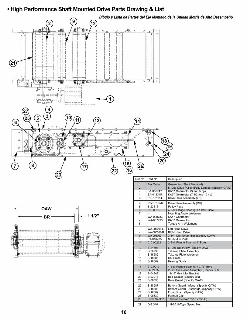
Ref No Part No Description
12--3
Per Order -SA-006747SA-012345PT-016164-L
Gearmotor (Shaft mounted)8” Dia. Drive Pulley (Fully Lagged) (Specify OAW)KA57 Gearmotor (3 and 5 hp)KA67 Gearmotor (7 1/2 and 10 hp)Drive Plate Assembly (LH)
4567--8
PT-016164-RB-23616910.0018-WA-009783WA-007993-
Drive Plate Assembly (RH)Pulley Plate4-Bolt Flange Bearing-1 11/16” Boremounting Angle WeldmentKA57 GearmotorKA67 GearmotorTorque Arm Weldment
--9
1011
WA-005018-LWA-005018-RWA-005063PT-016285010.00222
Left Hand DriveRight Hand Drive3 3/4” Dia. Snub Idler (Specify OAW)Snub Idler Plate2-Bolt Flange Bearing-1” Bore
1213141516
B-24801B-20935B-18682B-18686B-18669
6” Dia Tail Pulley (Specify OAW)Take-up Plate AssemblyTake-up Plate WeldmentHD GuideBearing Guide
1718192021
910.0017G-02425B-04842B-03916B-08336
4-Bolt Flange Bearing-1 7/16” Bore2 5/8” Dia Roller Assembly (Specify BR)11/16” Hex Idler BracketBed Spacer (Specify BR)Rear Guard (Specify OAW)
2223242526
B-18687B-18688B-18689B-08339B-03092-352
Bottom Guard (Infeed) (Specify OAW)Bottom Guard (DIscharge) (Specify OAW)Front Guard (Specify OAW)Formed ClipTake-up Screw-1/2-13 x 22” Lg
27 049.310 1/4-20 U-Type Speed Nut
• High Performance Shaft Mounted Drive Parts Drawing & List Dibujo y Lista de Partes del Eje Montado de la Unidad Motriz de Alto Desempeño
16
7
1
19
11
122
22
5
89 3
18
20
22
1615
25
17
4
14
6
1023
OAWBR
24
1321
26
27
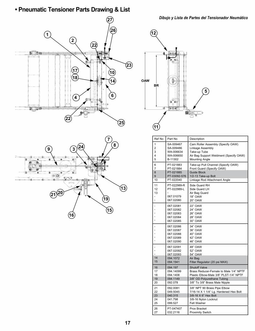
• Pneumatic Tensioner Parts Drawing & List Dibujo y Lista de Partes del Tensionador Neumático
Ref No Part No Description
12345
SA-009467SA-009486WA-006634WA-006650B-11302
Cam Roller Assembly (Specify OAW)Linkage AssemblyTake-up TubeAir Bag Support Weldment (Specify OAW)mounting Angle
678910
PT-021883PT-021884PT-021885PT-03092-576PT-022040
Take-up Pull Channel (Specify OAW)Front Guard (Specify OAW)Guide Block1/2-13 Take-up BoltLinkage Rod Attachment Angle
111213--
PT-022989-RPT-022989-L-067.01079067.02080
Side Guard RHSide Guard LHAir Bag Guard18” OAW20” OAW
-----
067.02081067.02082067.02083067.02084067.02085
22” OAW24” OAW26” OAW28” OAW30” OAW
-----
067.02086067.02087067.02088067.02089067.02090
34” OAW36” OAW40” OAW42” OAW46” OAW
---1415
067.02091067.02092067.02093094.1072094.1941
48” OAW52” OAW54” OAWAir BagFilter Regulator (20 psi mAX)
1617181920
094.197094.14099094.1408094.1149092.078
Shutoff ValveBrass Reducer-Female to male 1/4” NPTFPlastic Elbow-male 3/8” PLST-1/4” NPTF3/8” OD Polyurethane Tubing3/8” To 3/8” Brass male Nipple
2122232425
092.0081049.5045040.315041.798099.527
3/8” NPT 90 Brass Pipe Elbow7/16-14 X 1 1/4” Lg. Hardened Hex Bolt3/8-16 X 6” Hex Bolt3/8-16 Nylon LocknutFelt Washer
2627
PT-047407032.2116
Prox BracketProximity Switch
17
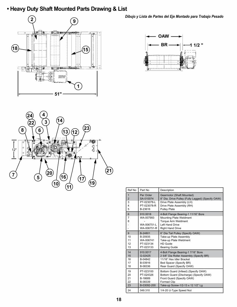
• Heavy Duty Shaft Mounted Parts Drawing & List Dibujo y Lista de Partes del Eje Montado para Trabajo Pesado2 9
18 15
1
8
51"
7
1423
4
12
3
136
2422
1721
111910
16520
12"
1 1/2 "
OAW
BR
Ref No Part No Description
12345
Per OrderSA-010074PT-023078-LPT-023078-RB-23616
Gearmotor (Shaft mounted)8” Dia. Drive Pulley (Fully Lagged) (Specify OAW)Drive Plate Assembly (LH)Drive Plate Assembly (RH)Pulley Plate
678--
910.0018WA-007993 -WA-006751-LWA-006751-R
4-Bolt Flange Bearing-1 11/16” Boremounting Plate WeldmentTorque Arm WeldmentLeft Hand DriveRight Hand Drive
910111213
B-24801B-20935WA-006741PT-023134PT-023133
6” Dia Tail Pulley (Specify OAW)Take-up Plate AssemblyTake-up Plate WeldmentHD GuideBearing Guide
1415161718
910.0017G-02425B-04842B-03916B-08336
4-Bolt Flange Bearing-1 7/16” Bore2 5/8” Dia Roller Assembly (Specify BR)11/16” Hex Idler BracketBed Spacer (Specify BR)Rear Guard (Specify OAW)
1920212223
PT-023100PT-024326B-18689B-08339B-03092-200
Bottom Guard (Infeed) (Specify OAW)Bottom Guard (DIscharge) (Specify OAW)Front Guard (Specify OAW)Formed ClipTake-up Screw-1/2-13 x 12 1/2” Lg
24 049.310 1/4-20 U-Type Speed Nut
18

34
2 12
13 16 17 1110617
8
59
14
15
6" DISCHARGE TAIL(eXtremO de desCarga de 6")
3 1/4" INFEED TAIL(eXtremO de Carga de 3 1/4")
18
1921
20
• Tail Assembly Parts Drawing & List Dibujo y Lista de Partes del Eje Montaje del Extremo de Retorno
Ref No Part No Description
-1234
-WA-008284WA-011933WA-011934B-21155
6” System End (Discharge)6” Dia. Tail Pulley Assembly (Specify BR)RH Channel AssemblyLH Channel Assembly Slider Plate Assembly (Specify OAW)
56789
PT-042063B-14743B-20445090.262010.10372
Bearing Spacer - 1 7/16” Bore1.9” Dia. Galv. Roller (Specify BR)1.9” Dia Galv Pop-out Roller (Specify BR)Pop-out Roller Bracket3-Bolt Flange Bearing - 1 7/16” Bore
10-111213
093.215-SA-000676PT-006399B-23316
Roller Bracket3 1/4” System End (Infeed)3 1/4” Dia. Tail Pulley Assembly (Specify BR)ChannelSplice Plate
1415161718
B-03191B-23060PT-006398B-25643SA-035140
Butt CouplingSlider Pan (Specify BR)Pulley mountNip Point Guard (Specify BR)2-1/2” Dia. Snub/Idler Roller (Specify BR)
192021
B-13708B-13707B-14734-H
Snub Guard (Specify BR)Snub Guard mounting Bracket11/16” Hex Idler Bracket
19
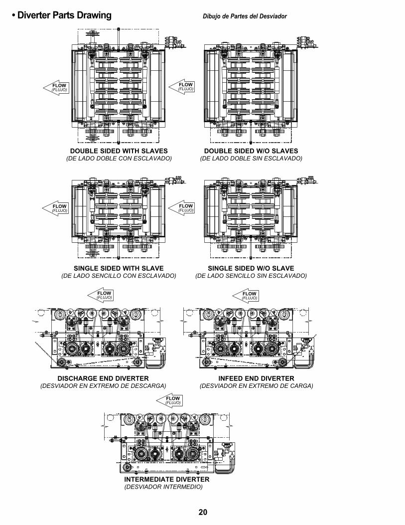
• Diverter Parts Drawing Dibujo de Partes del Desviador
FLOW(FlUJO)
FLOW(FlUJO)
FLOW(FlUJO)
FLOW(FlUJO)
FLOW(FlUJO)
FLOW(FlUJO)
FLOW(FlUJO)
DOUBLE SIDED WITH SLAvES(de ladO dOble COn esClaVadO)
DOUBLE SIDED W/O SLAvES(de ladO dOble sIn esClaVadO)
SINGLE SIDED WITH SLAvE(de ladO senCIllO COn esClaVadO)
DISCHARGE END DIvERTER(desVIadOr en eXtremO de desCarga)
INFEED END DIvERTER(desVIadOr en eXtremO de Carga)
INTERMEDIATE DIvERTER(desVIadOr IntermedIO)
SINGLE SIDED W/O SLAvE(de ladO senCIllO sIn esClaVadO)
20
111
8
243
FLOW
FLOW
SINGLE
DOUBLE
40
42
41
44
38
45
404131
33
43
32
109
1327 2422
1223
1716
34356
4647
3637
5720
1821
19
25
29 28
3930
148
1526
11
SINGLESIDED
(DE LADO SENCILLO)
DOUBLESIDED
(DE LADO DOBLE)
END DIvERTER(WITH SNUB
IDLER)(EXTREMO DEL
DESVIADOR)[CON RODILLO
DE ALINEACION]
INTERMEDIATE DIvERTER (WITH IDLER ONLY)(DESVIADOR INTERMEDIO) [CON GUIA SOLAMENTE]
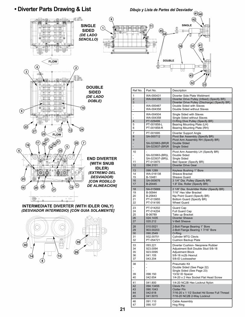
• Diverter Parts Drawing & List Dibujo y Lista de Partes del Desviador
Ref No. Part No. Description
123--
WA-000431WA-004358-WA-000467WA-004358
Diverter Side Plate WeldmentDiverter Drive Pulley (Infeed) (Specify BR)Diverter Drive Pulley (Discharge) (Specify BR)Double Sided with SlavesDouble Sided without Slaves
--456
WA-004504WA-004358PT-029499PT-001858-LPT-001858-R
Single Sided with SlavesSingle Sided without SlavesO-RIng Dive Pulley (Specify BR)Bearing mounting Plate (LH)Bearing mounting Plate (RH)
789--
PT-001695SA-000712-SA-023963-(BR)RSA-023937-(BR)R
Diverter Support AnglePivot Bar Assembly (Specify BR)Pivot Arm Assembly RH (Specify BR)Double SIdedSingle Sided
10--1112
-SA-023963-(BR)LSA-023937-(BR)LPT-013975094.3101
Pivot Arm Assembly LH (Specify BR)Double SidedSingle SidedBed Spacer (Specify BR)Diverter Drive Gear
1314151617
099.1289WA-016138B-10481SA-000676B-20445
Keyless Bushing 1” BoreSheave BracketSheave Guard3 1/4” Dia. Pulley (Specify BR)1.9” Dia. Roller (Specify BR)
1819202122
SA-015669B-00944B-25643PT-013955PT-014195
2 1/8” Dia. Snub/Idler Roller (Specify BR)7/16” Hex Idler BracketNip Point Guard (Specify BR)Bottom Guard (Specify BR)Wheel Guard
2324252627
PT-014202PT-014204B-06789024.1435020.212
Guard CapFull Guard CapTake up BracketDiverter SheaveV-Belt Sheave
2829303132
010.0021903.00203090.2549932.00751PT-054721
2-Bolt Flange Bearing 1” Bore2-Bolt Flange Bearing 1 7/16” BoreO-RingCylinder mTG ClevisCushion Backup Plate
3334353637
093.221923.0094923.0095041.105043.204
Diverter Cushion- Neoprene RubberAdjustment Bolt Double Stud 5/8-18Adjustment Block5/8-18 nc2b Hexnut5/8-ID Lockwasher
38--3940
---098.150042.654
Pneumatic KitDouble Sided (See Page 22)Single Sided (See Page 23)13/32 ID Spacer1/4-20 x 2 Hex Socket Flat Head Screw
4142434445
041.800094.13455090.1043042.618041.5015
1/4-20 NC2B Hex Locknut NylonClevis PinClotter Pin7/16-20 x 1 1/2 Socket Hd Screw Full Thread7/16-20 NC2B 2-Way Locknut
4647
091.110090.107
Cable AssemblyHog RIng
21
104
8
37
2
15 16 17 18 13
14
11 12
6
1
9
5
FLOW/FLUJO
POSITION #1BOTH STRAIGHT
(LA POSICIÓN #1 AMBOS DERECHO)
FIRST BANK(PRIMER BANCO)
SECOND BANK(SEGUNDO BANCO)
INOUT
4
3
4
3
4
3
1
1
1
2
2
2 1
2
20
1719
21
22
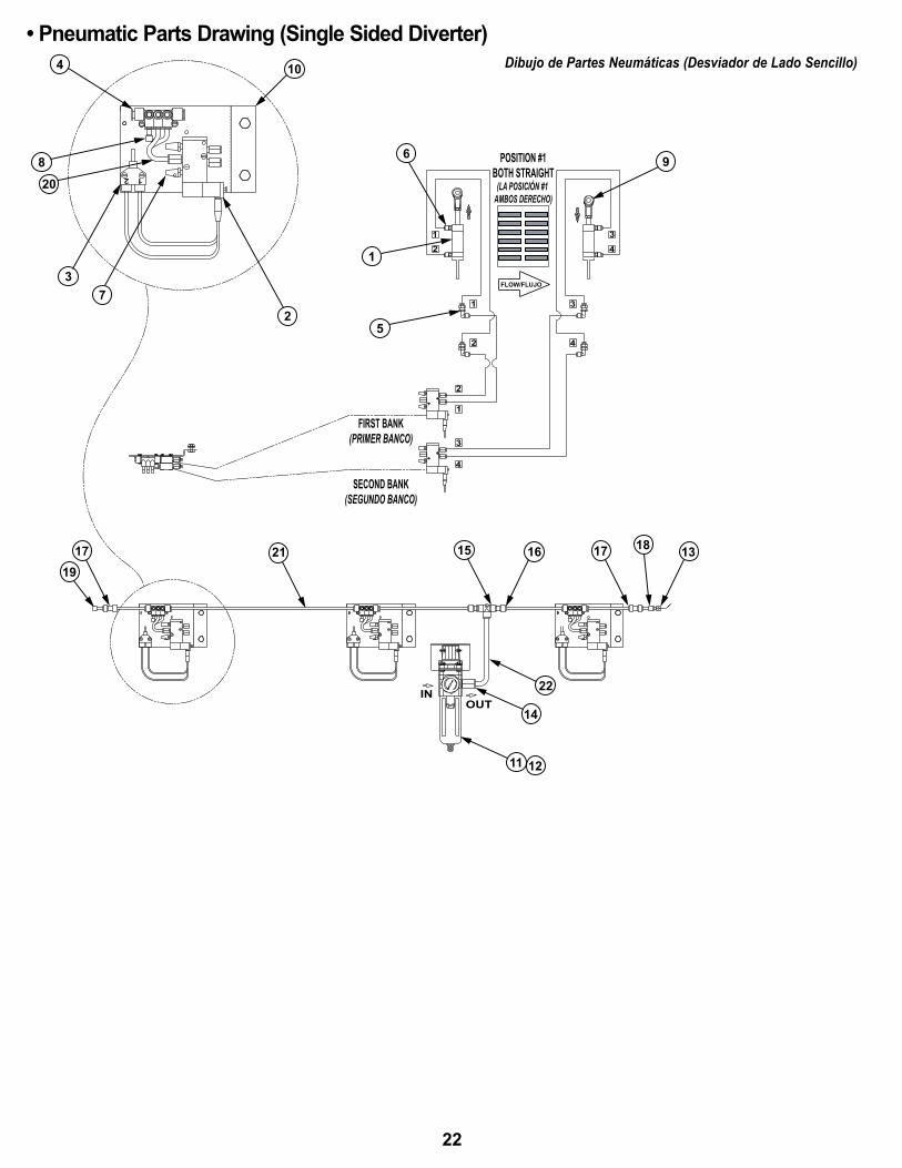
• Pneumatic Parts Drawing (Single Sided Diverter) Dibujo de Partes Neumáticas (Desviador de Lado Sencillo)
22
2 1
104
8
37
2
15 16 17 18 13
14
11 12
6
1
9
5
FLOW/FlUJO
POSITION #1BOTH STRAIGHT
(pOsICIOn #1ambOs dereCHOs)
FIRST BANK LEFT(prImer banCO IzQUIerdO)
SECOND BANK LEFT(segUndO banCO IzQUIerdO)
FIRST BANK RIGHT(prImer banCO dereCHO)
SECOND BANK RIGHT(segUndO banCO dereCHO)
IN(entrada) OUT
(salIda)
4
2 4
1
34
12
78
56
3
8 6
7 5
3
6
5
2
1
8
7
20
1719 21
22
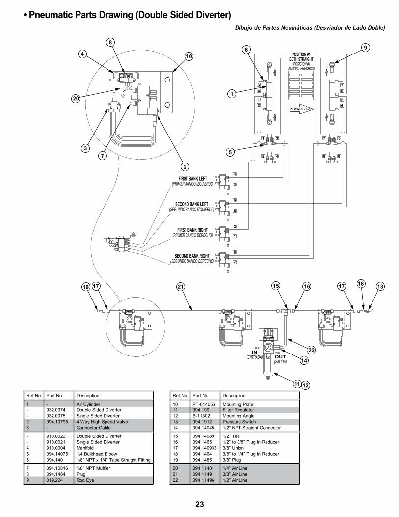
Ref No Part No Description
1--23
-932.0074932.0075094.10795-
Air CylinderDouble Sided DiverterSingle Sided Diverter4-Way High Speed ValveConnector Cable
--456
910.0022910.0021910.0004094.14075094.140
Double Sided DiverterSingle Sided Divertermanifold1/4 Bulkhead Elbow1/8” NPT x 1/4” Tube Straight Fitting
789
094.10816094.1484019.224
1/8” NPT mufflerPlugRod Eye
• Pneumatic Parts Drawing (Double Sided Diverter) Dibujo de Partes Neumáticas (Desviador de Lado Doble)
Ref No Part No Description
1011121314
PT-014056094.190B-11302094.1912094.14045
mounting PlateFilter Regulatormounting AnglePressure Switch1/2” NPT Straight Connector
1516171819
094.14089094.1465094.140933094.1464094.1485
1/2” Tee1/2” to 3/8” Plug in Reducer3/8” Union3/8” to 1/4” Plug in Reducer3/8” Plug
202122
094.11481094.1149094.11496
1/4” Air Line3/8” Air Line1/2” Air Line
23
11
9
10
29
27
13 26 28
4302
NOTE:LOCATE DRIVE ROLLER INSUPPORT BRACKET AS SHOWN(NOTA: UBIQUE EL RODILLO MOTRIZ EN LA ABRAZADERA DE SOPORTE COMO ES MOSTRADO)
15
25
24
30
1 3
7
6
23
22
21
20 1918
17
5
8
14 16 12
NOTE:LOCATE DRIVE ROLLERIN BOTTOM HOLE(NOTA: UBIQUE EL RODILLO MOTRIZ EN EL ORIFICIO INFERIOR)
RH SPUR(ESPUELA DE MANO DERECHA)
31
32
33
1 1/2"
OAW
BR
END vIEW(VISTA DESDE EL EXTREMO)
LH SPUR(ESPUELA DE MANO IZQUIERDA)
• Powered Spur Parts Drawing Dibujo de Partes del Espuelas Motorizadas
24
OAW
BR 1 1/2
6 1/2
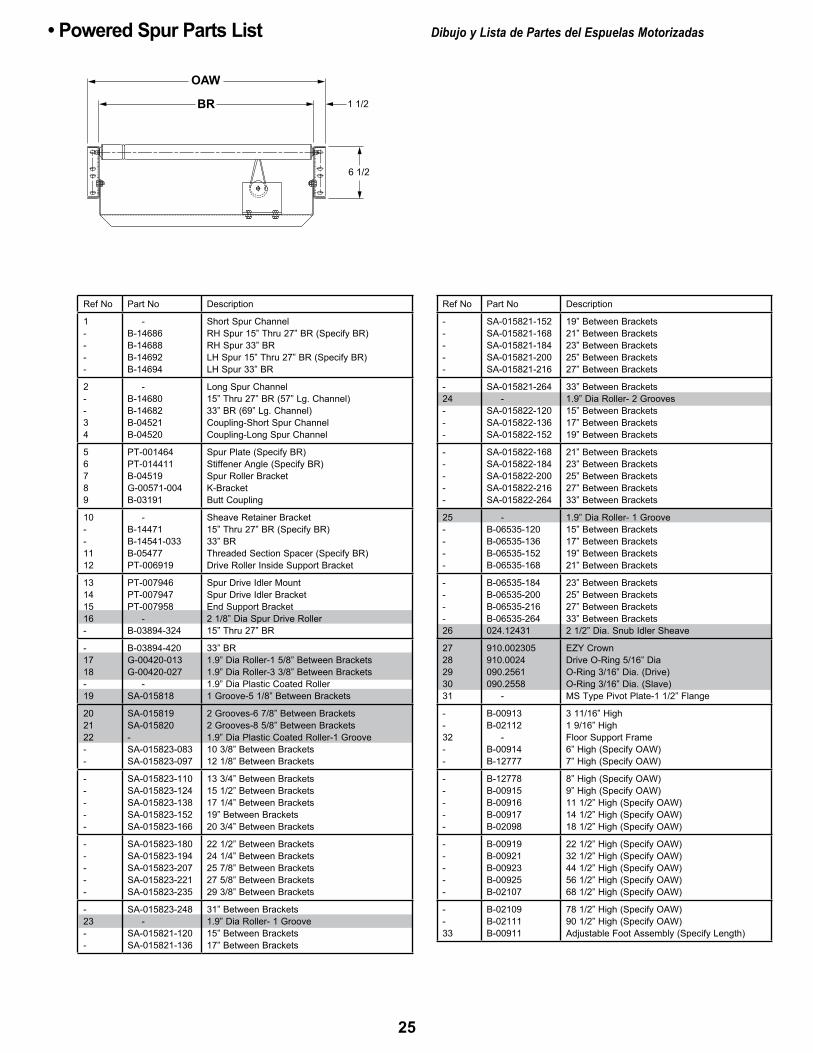
Ref No Part No Description
-----
SA-015821-152SA-015821-168SA-015821-184SA-015821-200SA-015821-216
19” Between Brackets21” Between Brackets23” Between Brackets25” Between Brackets27” Between Brackets
-24---
SA-015821-264 -SA-015822-120SA-015822-136SA-015822-152
33” Between Brackets1.9” Dia Roller- 2 Grooves15” Between Brackets17” Between Brackets19” Between Brackets
-----
SA-015822-168SA-015822-184SA-015822-200SA-015822-216SA-015822-264
21” Between Brackets23” Between Brackets25” Between Brackets27” Between Brackets33” Between Brackets
25----
-B-06535-120B-06535-136B-06535-152B-06535-168
1.9” Dia Roller- 1 Groove15” Between Brackets17” Between Brackets19” Between Brackets21” Between Brackets
----26
B-06535-184B-06535-200B-06535-216B-06535-264024.12431
23” Between Brackets25” Between Brackets27” Between Brackets33” Between Brackets2 1/2” Dia. Snub Idler Sheave
2728293031
910.002305910.0024090.2561090.2558 -
EzY CrownDrive O-Ring 5/16” DiaO-Ring 3/16” Dia. (Drive)O-Ring 3/16” Dia. (Slave)mS Type Pivot Plate-1 1/2” Flange
--32--
B-00913B-02112 -B-00914B-12777
3 11/16” High1 9/16” HighFloor Support Frame6” High (Specify OAW)7” High (Specify OAW)
-----
B-12778B-00915B-00916B-00917B-02098
8” High (Specify OAW)9” High (Specify OAW)11 1/2” High (Specify OAW)14 1/2” High (Specify OAW)18 1/2” High (Specify OAW)
-----
B-00919B-00921B-00923B-00925B-02107
22 1/2” High (Specify OAW)32 1/2” High (Specify OAW)44 1/2” High (Specify OAW)56 1/2” High (Specify OAW)68 1/2” High (Specify OAW)
--33
B-02109B-02111B-00911
78 1/2” High (Specify OAW)90 1/2” High (Specify OAW)Adjustable Foot Assembly (Specify Length)
Ref No Part No Description
1----
-B-14686B-14688B-14692B-14694
Short Spur ChannelRH Spur 15” Thru 27” BR (Specify BR)RH Spur 33” BR LH Spur 15” Thru 27” BR (Specify BR)LH Spur 33” BR
2--34
-B-14680B-14682B-04521B-04520
Long Spur Channel15” Thru 27” BR (57” Lg. Channel)33” BR (69” Lg. Channel)Coupling-Short Spur ChannelCoupling-Long Spur Channel
56789
PT-001464PT-014411B-04519G-00571-004B-03191
Spur Plate (Specify BR)Stiffener Angle (Specify BR)Spur Roller BracketK-BracketButt Coupling
10--1112
-B-14471B-14541-033B-05477PT-006919
Sheave Retainer Bracket 15” Thru 27” BR (Specify BR)33” BRThreaded Section Spacer (Specify BR)Drive Roller Inside Support Bracket
13141516-
PT-007946PT-007947PT-007958 -B-03894-324
Spur Drive Idler mountSpur Drive Idler BracketEnd Support Bracket2 1/8” Dia Spur Drive Roller 15” Thru 27” BR
-1718-19
B-03894-420G-00420-013G-00420-027 -SA-015818
33” BR1.9” Dia Roller-1 5/8” Between Brackets1.9” Dia Roller-3 3/8” Between Brackets1.9” Dia Plastic Coated Roller1 Groove-5 1/8” Between Brackets
202122--
SA-015819SA-015820-SA-015823-083SA-015823-097
2 Grooves-6 7/8” Between Brackets2 Grooves-8 5/8” Between Brackets1.9” Dia Plastic Coated Roller-1 Groove10 3/8” Between Brackets12 1/8” Between Brackets
-----
SA-015823-110SA-015823-124SA-015823-138SA-015823-152SA-015823-166
13 3/4” Between Brackets15 1/2” Between Brackets17 1/4” Between Brackets19” Between Brackets20 3/4” Between Brackets
-----
SA-015823-180SA-015823-194SA-015823-207SA-015823-221SA-015823-235
22 1/2” Between Brackets24 1/4” Between Brackets25 7/8” Between Brackets27 5/8” Between Brackets29 3/8” Between Brackets
-23--
SA-015823-248 -SA-015821-120SA-015821-136
31” Between Brackets1.9” Dia Roller- 1 Groove15” Between Brackets17” Between Brackets
• Powered Spur Parts List Dibujo y Lista de Partes del Espuelas Motorizadas
25

ÍNDICEIntrOdUCCIón recepción y desembalaje . . . . . . . . . . . . . . . . . . . . . . . . . . . . . . .26 Cómo Ordenar refaccionamiento . . . . . . . . . . . . . . . . . . . . . . . . .26InFOrmaCIón de segUrIdad . . . . . . . . . . . . . . . . . . . . . . . . . . . .26, 27InstalaCIón Instalación de soportes . . . . . . . . . . . . . . . . . . . . . . . . . . . . . . . . . .27 montaje del transportador . . . . . . . . . . . . . . . . . . . . . . . . . . . . . . .27 equipo eléctrico . . . . . . . . . . . . . . . . . . . . . . . . . . . . . . . . . . . . . . .28 arranque del transportador . . . . . . . . . . . . . . . . . . . . . . . . . . . . . .28 lubricación . . . . . . . . . . . . . . . . . . . . . . . . . . . . . . . . . . . . . . . . . . .28 Instalación de la banda . . . . . . . . . . . . . . . . . . . . . . . . . . . . . . . 29 alineación de la banda . . . . . . . . . . . . . . . . . . . . . . . . . . . . . 30, 31
mantenImIentO ajuste del desviador . . . . . . . . . . . . . . . . . . . . . . . . . . . . . . . 31, 32 alineación de la rueda del desviador . . . . . . . . . . . . . . . . . 31, 32 Instalación de la espuela . . . . . . . . . . . . . . . . . . . . . . . . . . . . . . 33 resolviendo problemas . . . . . . . . . . . . . . . . . . . . . . . . . . . . . . . . .34 lista del plan de mantenimiento . . . . . . . . . . . . . Cubierta posteriorpartes de repUestO dibujo de partes del prosort sC . . . . . . . . . . . . . . . . . . . . . . . . 12 dibujo de partes del prosort sC . . . . . . . . . . . . . . . . . . . . . . . . 13 dibujo de partes del prosort sC . . . . . . . . . . . . . . . . . . . . . . . . 14 lista de partes del prosort sC . . . . . . . . . . . . . . . . . . . . . . . . . . 15 dibujo y lista de partes del motor montado en el eje de alto desempeño . . . . . . . . . . . . . . . . . . . . . . . . 16 dibujo y lista de partes del tensionador neumático . . . . . . . . . 17 dibujo y lista de partes motor montado en el eje para trabajo pesado . . . . . . . . . . . . . . . . . . . . . . . . . . 18 dibujo y lista de partes del ensamble del extremo de retorno . . . . . . . . . . . . . . . . . . . . . . . . . . . . 19 dibujo de partes del desviador . . . . . . . . . . . . . . . . . . . . . . . . . 20 dibujo y lista de partes del desviador . . . . . . . . . . . . . . . . . . . 21 dibujo de partes neumáticas . . . . . . . . . . . . . . . . . . . . . . . . . . . 22 dibujo y lista de partes neumáticas . . . . . . . . . . . . . . . . . . . . . 23 dibujo de partes de espuelas motorizadas . . . . . . . . . . . . . . . . 24 lista de partes de espuelas motorizadas . . . . . . . . . . . . . . . . . 25
INTRODUCCIÓNeste manual proporciona información para instalar, operar y dar mantenimiento a su transportador . se proporciona una lista completa de partes, con el refaccionamiento recomendado resaltado en gris . también se proporciona información importante de seguridad a lo largo de este manual . para seguridad del personal y para un mejor funcionamiento del transportador, se recomienda que se lean y se sigan cada una de las instrucciones proporcionadas en este manual .
• Recepción y Desembalaje1. Verifique el número de partes recibidas con respecto al conocimiento del embarque .2. Examine las condiciones del equipo para determinar si algún daño ha ocurrido durante el transporte .3 . traslade todo el equipo al área de instalación .4. Remueva todos los empaques y verifique si hay partes adicionales que puedan estar sujetas al equipo. Asegúrese de que estas partes (u otras partes ajenas al equipo) sean removidas .
• Cómo Ordenar Refaccionamientoen este manual encontrará dibujos de las partes con listas completas de las refacciones . partes pequeñas, como tornillos y tuercas no están incluidos . para ordenar refaccionamiento:1 . Contacte al representante que le vendió el transportador o el distribuidor de Hytrol más cercano .2. Proporcione el Modelo del Transportador y el Número de Serie o Númerode la Orden de Fabricación .3. Proporcione el Número de las partes y descripción completa que apareceen la lista de partes .4 . proporcione el tipo de motor . ejemplo- Unidad motriz en extremo Final de 8”, Unidad motriz Central de 8”, etc .5 . si su equipo se encuentra en una situación crítica, comuníquese con nosotros inmediatamente .
NOTA: Si algún daño ha ocurrido o faltan partes, contacte a su integrador Hytrol.
INFORMACIÓN DE SEGURIDAD• InstalaciónprOteCCIón Y segUrIdadInterfaz de los equipos . Cuando dos o más piezas de equipo son interconectadas, se deberá prestar especial atención a la zona de la interfaz para asegurar la presencia de guardas y dispositivos de seguridad adecuados .localización o posición . para procurar la protección de los trabajadores ante los riesgos, todas las partes móviles expuestas de la maquinaria deberán ser aseguradas mecánica o eléctricamente, o protegidas mediante el cambio de localización o posición .La presencia alejada del público o empleado constituirá una medida de seguridad por ubicación .Cuando el transportador esté instalado sobre pasillos, corredores o estaciones de trabajo; se considera protegido únicamente por localización o posición si todas las partes en movimiento están mínimo a 8 pies (2,44 m) por encima del piso o área de tránsito . de otra manera se pueden ubicar de tal manera que los empleados no entren en contacto con partes móviles peligrosas sin querer .aunque los transportadores aéreos pueden estar protegidos por su ubicación, deben proporcionarse guardas para evitar derrames: guardas laterales e inferiores; esto si el producto pued e caerse del transportador y así mantener al personal fuera de peligro .espaCIO lIbre sUperIOrCuando los transportadores son instalados sobre pasillos, salidas o corredores; se deberá disponer de un espacio libre mínimo de 6 pies 8 pulgadas (2,032 m), medido verticalmente desde el suelo o mezanine a la parte más baja del transportador o de las guardasCuando el funcionamiento del sistema sea afectado al guardar la distancia mínima de 6 pies 8 pulgadas (2,032 m), deberán autorizarse pasillos alternos de emergencia .es posible permitir el paso bajo transportadores con menos de 6 pies 8 pulgadas (2 .032 m) desde el piso, con excepción de las salidas de emergencia . para esto se requiere una señalización apropiada que indique altura baja .
• Operacióna) sólo los empleados capacitados están autorizados a operar los transportadores . el entrenamiento debe incluir: operación bajo condiciones normales y en situaciones de emergencia .b) Cuando la seguridad de los trabajadores dependa de dispositivos de paro y/o arranque, tales dispositivos deben mantenerse libres de obstrucciones para permitir un acceso rápido .C) el área alrededor de los puntos de carga y descarga deberá mantenerse libre de obstrucciones que puedan poner en peligro al personal .d) ninguna persona podrá viajar en el elemento de carga de un transportador sin excepción; al menos que esta persona esté específicamente autorizado por el propietario o el empleador . en esas circunstancias, el empleado deberá montarse solamente en un transportador que tenga incorporado en sus plataformas de estructura de soporte o estaciones de control especialmente diseñadas para el transporte de personal . esto no es permisible en un transportador vertical .E) El personal que trabaja con un transportador, o cerca de uno; debe ser notificado de la ubicación y operación de los dispositivos de paro pertinentes .F) Un transportador debe ser usado únicamente para transportar el material que es capaz de cargar .g) las indicaciones de seguridad del transportador no deben ser alteradas bajo ninguna circunstancia, especialmente si esto pone en peligro al personal .H) las Inspecciones de rutina, así como el mantenimiento correctivo y preventivo deben ser llevados a cabo de modo que todos los dispositivos e indicaciones de seguridad sean respetados y funcionen adecuadamente .I) El personal debe ser notificado del peligro potencial que puede ser causado en los transportadores debido al uso de cabello largo, ropa holgada y joyería.J) nunca se debe dar mantenimiento o servicio a un transportador mientras se encuentre en operación, a menos que el mantenimiento o servicio apropiado lo requiera. En este caso, el personal debe ser notificado del peligro que esto representa y de cómo se puede llevar a cabo el procedimiento de la manera más segura .K) los dueños de los transportadores deben asegurarse de que las etiquetas de
Refaccionamiento Recomendado se Resalta en GrisNúmero de Serie HYTROL(localizado cerca de la Unidad motriz en modelos motorizados) .
Hytrol ConveyorCompany, Inc.
JONESBORO, ARKANSAS
SERIAL # 978747
26
seguridad se encuentren colocadas sobre el transportador, indicando los peligros que implica la operación de sus equipos .
¡PRECAUCIÓN!Debido a que el transportador contiene muchas partes en movimiento,
todo el personal que se encuentra en el área debe ser notificado cuando el equipo esté a punto de arrancar.
• Mantenimientotodo mantenimiento, incluyendo lubricación y ajustes, debe ser llevado a cabo únicamente por personal entrenado y calificado.es importante que el programa de mantenimiento establecido asegure que todos los componentes del transportador reciban el mantenimiento en condiciones que no constituyan un peligro para el personal .Cuando un transportador es detenido para propósitos de mantenimiento, los dispositivos de arranque y de potencia deben ser asegurados o etiquetados de acuerdo a un procedimiento formalizado diseñado para proteger a todas las personas o grupos que trabajan con el transportador en caso de que ocurra algún arranque inesperado .Verifique todos los dispositivos y guardas de seguridad antes de arrancar el equipo para una operación normal .aunque parezca práctico, nunca lubrique los transportadores mientras se encuentren en movimiento . sólo el personal capacitado que conoce de los peligros de un transportador en movimiento puede realizar la lubricación .
guardas de seguridadmantenga todas las guardas y dispositivos de seguridad en su posición y en buenas condiciones .etiquetas de seguridadEtiquetas de seguridad han sido ubicadas en diferentes puntos del equipo para alertar de los peligros potenciales existentes; esto en un esfuerzo por reducir la posibilidad de lesiones en el personal que trabaja alrededor de un transportador HYTROL. Por favor, revise el equipo e identifique todas las etiquetas de seguridad. Asegúrese de que el personal conozca y obedezca estas advertencias. Refiérase al manual de seguridad para ver ejemplos de etiquetas de advertencias.
¡RECUERDE!No remueva, reúse o modifique el material que incluye el equipo para
ningún propósito que no sea para el que fueron diseñados originalmente.
¡PRECAUCIÓN!Sólo personal capacitado debe manipular la dirección de una banda del
transportador, lo cual debe hacerse mientras el transportador se encuentra en movimiento. No intente direccionar la banda si el transportador está
cargado.
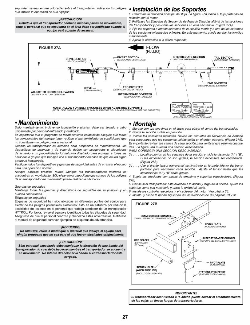
• Instalación de los Soportes1 . determine la dirección principal del flujo . la figura 27a indica el flujo preferido en relación con el motor .2 . refiérase las etiquetas de secuencia de armado situadas al final de las secciones del transportador y posicione las secciones en esta secuencia . (Figura 27a) .3 . Fije los soportes a ambos extremos de la sección motriz y a uno de los extremos de las secciones intermedias o finales . en este momento, puede apretar los tornillos manualmente . 4 . ajuste la elevación a la altura requerida .
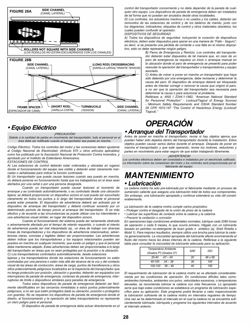
• Montaje1 . marque con tiza una línea en el suelo para ubicar el centro del transportador . 2 . ponga la sección motriz en posición .3 . Instale las secciones restantes . revise las etiquetas de secuencia de armado para asegurarse que las secciones unidas estén en el orden correcto . (Figura 27a) . es importante revisar las camas de cada sección para verificar que estén escuadra-das . la figura 28a muestra una sección descuadrada .para COrregIr Una seCCIOn desCUadrada3a . . . . localice puntos en las esquinas de la sección y mida la distancia “a” y “b” .
si las dimensiones no son iguales, la sección necesitará ser escuadrada . (Figura 28b) .
3b . . . . Use el tirante tensor transversal suministrado en la parte inferior del trans-portador para escuadrar cada sección. Ajuste el tensor hasta que las dimensiones “a” y “b” sean iguales .
4 . sujete las secciones con placas de empalme y soportes espaciadores . (Figura 27b)5. Revise si el transportador está nivelado a lo ancho y largo de la unidad. Ajuste los soportes como sea necesario y ancle la unidad al suelo .6 . Instale los controles eléctricos y el cableado del motor . Vea página 28 .7 . Instale y alinee la banda siguiendo las instrucciones de las páginas 29 y 31 .
¡IMPORTANTE!El transportador desnivelado a lo ancho puede causar el amontonamiento de las cajas en líneas largas de transportadores.
(WHEN SUPPLIED)RETURN IDLER
SUPPORT SPACER CHANNEL
CONVEYOR SIDE CHANNEL
PIVOT PLATE
STATIONARY SUPPORT
SPLICE PLATE(PLACA DE EMPALME)
(SOPORTE DEL CANAL ESPACIADOR)
(RODILLO DE ALINEACIÓN)
BED SPACER(ESPACIADORDE CAMA)
(PLACA PIVOTE)
(SOPORTE ESTACIONARIO)
(CANAL LATERAL DEL TRANSPORTADOR)
FIGURE 27B
FLOW(FLUJO)
DRIVE SECTION(SECCION MOTRIZ)
ADJUST TO DESIRED ELEVATION(AJUSTE A LA ALTURA DESEADA)
DRIVE(UNIDAD MOTRIZ)
END DIVERTER(DESVIADOR DEL EXTREMO)
END DIVERTER(DESVIADOR DEL EXTREMO)
TAIL SECTION(SECCION DE RETORNO)
INTERMEDIATE SECTION(SECCION INTERMEDIA)
DIVERT SECTION(SECCION DE DESVIACIÓN)
INTERMEDIATE DIVERTER(DESVIADOR-INTERMEDIO)
"MATCH-MARK" NUMBERS(ETIQUETAS DE SECUENCIA DE ARMADO)
MARKCONVEYOR F.0.#ITEM TO
HYTROL CONVEYOR CO. INC.JONESBORO, AR
A
1212345
MARKCONVEYOR F.0.#ITEM TO
HYTROL CONVEYOR CO. INC.JONESBORO, AR
A
1 212345NOTE: ALLOW FOR BELT THICKNESS WHEN ADJUSTING SUPPORTS
(NOTA: DEJE ESPACIO SUFICIENTE PARA EL ESPESOR DE LA BANDA CUANDO AJUSTE LOS SOPORTES)
FIGURE 27A
27
• Equipo Eléctrico
Código eléctrico: todos los controles del motor y las conexiones deben ajustarse al Código nacional de electricidad, (artículo 670 u otros artículos aplicables) como fue publicado por la asociación nacional de protección Contra Incendios, y aprobado por el Instituto de estándares americanos .estaCIOnes de COntrOla) las estaciones de control deberán estar ordenadas y ubicadas en lugares donde el funcionamiento del equipo sea visible y deberán estar claramente mar-cadas o señalizadas para indicar la función controlada .B) Un transportador que pueda causar lesiones cuando sea puesto en marcha, no deberá ponerse en funcionamiento hasta que los trabajadores en el área sean alertados por una señal o por una persona designada . Cuando un transportador pueda causar lesiones al momento de arranque y es controlado automáticamente, o es controlado desde una ubicación lejana; se deberá proporcionar un dispositivo sonoro el cual pueda ser escuchado claramente en todos los puntos a lo largo del transportador donde el personal pueda estar presente . el dispositivo de advertencia deberá ser activado por el dispositivo de arranque del transportador y deberá continuar sonando por un determinado periodo de tiempo previo al arranque del transportador . si es más efectivo y de acuerdo a las circunstancias se puede utilizar una luz intermitente o una advertencia visual similar, en lugar del dispositivo sonoro . Cuando el funcionamiento del sistema pueda ser seriamente obstruido o adversamente afectado por el tiempo de retardo requerido, o cuando el intento de advertencia pueda ser mal interpretado (ej ., un área de trabajo con diversas líneas de transportadores y los dispositivos de advertencia relacionados), adver-tencias claras, concisas y legibles deben ser proporcionadas . las advertencias deben indicar que los transportadores y los equipos relacionados pueden ser puestos en marcha en cualquier momento, que existe un peligro y que el personal debe mantenerse alejado . estas advertencias deben ser proporcionadas a lo largo del transportador en áreas que no sean protegidas por la posición o la ubicación .C) los transportadores controlados automáticamente, desde estacioneslejanas y los transportadores donde las estaciones de funcionamiento no estén controladas por una persona o estén más allá del alcance de la voz y del contacto visual de las áreas de conducción, áreas de carga, puntos de transferencia y otros sitios potencialmente peligrosos localizados en la trayectoria del transportador que no tenga protección por posición, ubicación o guardas, deberán ser equipados con interruptores de parada de emergencia, cordones de parada de emergencia, inter-ruptores de límite o dispositivos similares para paradas de emergencia . todos estos dispositivos de parada de emergencia deberán ser fácil-mente identificables en las cercanías inmediatas a estos puntos potencialmente peligrosos, a no ser que estén protegidos dada su ubicación, posición o protegidos con guardas . no se requieren los dispositivos de parada de emergencia donde el diseño, el funcionamiento y la operación de tales transportadores no represente un claro peligro para el personal . el dispositivo de parada de emergencia debe actuar directamente en el
control del transportador concerniente y no debe depender de la parada de cual-quier otro equipo . los dispositivos de parada de emergencia deben ser instalados de tal forma que no puedan ser anulados desde otras localidades .d) los controles, los actuadores inactivos o no usados y los cables, deberán ser removidos de las estaciones de control y de los tableros de mando, junto con los diagramas, indicadores, etiquetas de control y otros materiales obsoletos, los cuales pueden confundir al operador .dIspOsItIVOs de segUrIdada) todos los dispositivos de seguridad, incluyendo la conexión de dispositivos eléctricos, deben estar dispuestos para operar en una manera de “Fallo - seguro”; es decir, si se presenta una pérdida de corriente o una falla en el mismo disposi-tivo, esto no debe representar ningún peligro.
b) paros de emergencia y reinicio . los controles del transporta-dor deberán estar dispuestos de tal manera que, en caso de un paro de emergencia se requiera un inicio o arranque manual en la ubicación donde el paro de emergencia se presentó para poder reanudar la operación del transportador o transportadores y equipo asociado .C) Antes de volver a poner en marcha un transportador que haya sido detenido por una emergencia, debe revisarse y determinar la causa del paro . el dispositivo de arranque deberá ser bloqueado antes de intentar corregir o remover la causa que originó el paro, a no ser que la operación del transportador sea necesaria para determinar la causa o para solucionar el problema .refiérase a: ans I z244 .1-1982, “american national standard for personnel protection” - lockout/tagout of energy sources - minimum safety requirements and OsHa standard number 29 CFR 1910.147 “The Control of Hazardous Energy (Lockout/tagout) .”
OPERACIÓN• Arranque del TransportadorAntes de poner en marcha el transportador, revise si hay objetos ajenos que puedan haber sido dejados dentro del transportador durante la instalación. Estos objetos pueden causar serios daños durante el arranque . después de poner en marcha el transportador y que esté operando, revise los motores, reductores y partes en movimiento para estar seguro de que están trabajando libremente .
MANTENIMIENTO• LubricaciónLa cadena motriz ha sido pre-lubricada por el fabricante mediante un proceso de sumersión caliente que asegura una lubricación total de todos sus componentes . Sin embargo, una lubricación apropiada y continua extenderá su vida útil consid-erablemente .
la lubricación de la cadena motriz cumple varios propósitos:• Proteger contra el desgaste de la unión de pines de la cadena • Lubricar las superficies de contacto entre la cadena y la catarina• Prevenir la oxidación o corrosiónEn operaciones bajo condiciones ambientales normales, lubrique cada 2080 horas de operación o cada 6 meses, lo que ocurra primero . Hágalo con un lubricante basado en petróleo no-detergente de buen grado o sintético (ej. Shell Rotella o Mobil 1). Para mejores resultados, siempre utilice una brocha para lubricar la cade-na generosamente . la viscosidad apropiada del lubricante afecta enormemente el fluido del mismo hacia las áreas internas de la cadena. Refiérase a la siguiente tabla para consultar la viscosidad de lubricante adecuada para su aplicación .
el requerimiento de lubricación de la cadena motriz se ve afectado considerable-mente por las condiciones de operación . en condiciones difíciles tales como: ambientes húmedos, ambientes con polvo, velocidades excesivas, o temperaturas elevadas, se recomienda lubricar la cadena con más frecuencia . lo apropiado sería que bajo estas condiciones se establezca un programa de lubricación espe-cífico para su aplicación . este programa podrá llevarse a cabo inspeccionando la lubricación suficiente de la cadena motriz en intervalos regulares de tiempo . Una vez se ha determinado el intervalo en el cual la cadena no se encuentra sufi-cientemente lubricada, lubríquela y programe los siguientes intervalos de acuerdo al intervalo anterior .
SIDE CHANNEL(CANAL LATERAL)
ROLLERS NOT SQUARE WITH SIDE CHANNELS(LOS RODILLOS NO ESTAN ESCUADRADOS CON LOS CANALES)
FIGURE 28A
"A"
"B"
SIDE CHANNEL(CANAL LATERAL)
(SHORT ROD)(VARILLA CORTA)
FRAME SPACER(ESPACIADOR DE CAMA)
TURNBUCKLE(TENSOR)
SIDE CHANNEL(CANAL LATERAL)
(LONG ROD) CROSSBRACING([VARILLA LARGA] TIRANTE TENSOR)
FIGURE 28B
¡preCaUCIón!debido a la cantidad de partes en movimiento del transportador, todo el personal en el
área debe ser notificado cuando el transportador sea puesto en marcha.
¡adVertenCIa!los controles eléctricos deben ser conectados e instalados por un electricista calificado . la información sobre las conexiones del motor y los controles será proporcionada por el
fabricante del equipo .
temperatura ambiente(grados Fº) (grados Cº)
sae IsO
20-40 -07 – 04 20 46 o 6840-100 04 – 38 30 100100-120 38 – 49 40 150
28
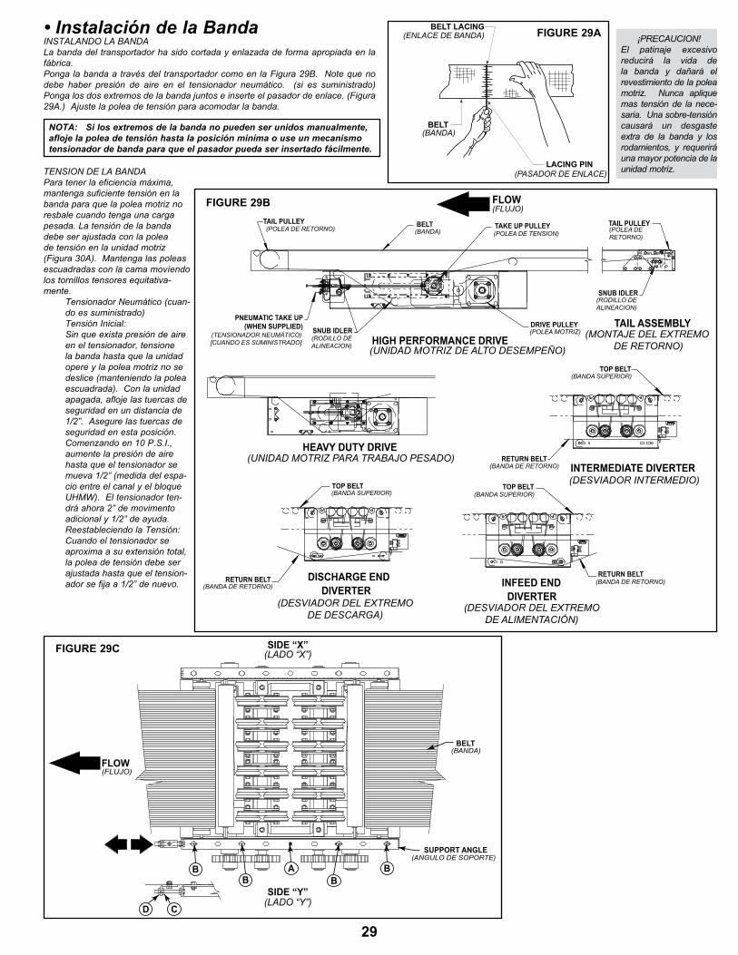
• Instalación de la BandaInstalandO la bandaLa banda del transportador ha sido cortada y enlazada de forma apropiada en la fábrica . ponga la banda a través del transportador como en la Figura 29b . note que no debe haber presión de aire en el tensionador neumático. (si es suministrado) ponga los dos extremos de la banda juntos e inserte el pasador de enlace . (Figura 29a .) ajuste la polea de tensión para acomodar la banda .
tensIOn de la bandapara tener la eficiencia máxima, mantenga suficiente tensión en la banda para que la polea motriz no resbale cuando tenga una carga pesada . la tensión de la banda debe ser ajustada con la polea de tensión en la unidad motriz (Figura 30a) . mantenga las poleas escuadradas con la cama movíendo los tornillos tensores equitativa-mente . tensionador neumático (cuan-
do es suministrado) tensión Inicial: sin que exista presión de aire
en el tensionador, tensione la banda hasta que la unidad opere y la polea motriz no se deslice (manteniendo la polea escuadrada) . Con la unidad apagada, afloje las tuercas de seguridad en un distancia de 1/2” . asegure las tuercas de seguridad en esta posición . Comenzando en 10 p .s .I ., aumente la presión de aire hasta que el tensionador se mueva 1/2” (medida del espa-cio entre el canal y el bloque UHmW) . el tensionador ten-drá ahora 2” de movimento adicional y 1/2” de ayuda .
reestableciendo la tensión: Cuando el tensionador se
aproxima a su extensión total, la polea de tensión debe ser ajustada hasta que el tension-ador se fija a 1/2” de nuevo .
NOTA: Si los extremos de la banda no pueden ser unidos manualmente, afloje la polea de tensión hasta la posición miníma o use un mecanismo tensionador de banda para que el pasador pueda ser insertado fácilmente.
¡preCaUCIOn!el patinaje excesivo reducirá la vida de la banda y dañará el revestimiento de la polea motriz . nunca aplique mas tensión de la nece-saria . Una sobre-tensión causará un desgaste extra de la banda y los rodamientos, y requerirá una mayor potencia de la unidad motriz .
TAIL ASSEMBLY
FLOW
DRIvE PULLEY
HIGH PERFORMANCE DRIvE
INTERMEDIATE DIvERTER
DIvERTERINFEED END
DIvERTERDISCHARGE ENDRETURN BELT
RETURN BELT
RETURN BELT
TOP BELT
TOP BELT
TOP BELT
TAIL PULLEY(pOlea de retOrnO)
SNUB IDLER(rOdIllO dealIneaCIOn)
(banda sUperIOr)
(banda de retOrnO)
(banda de retOrnO)
(banda de retOrnO)
(banda sUperIOr)
(banda sUperIOr)
(desVIadOr del eXtremOde desCarga)
(desVIadOr del eXtremOde alImentaCIón)
(mOntaJe del eXtremO de retOrnO)(UnIdad mOtrIz de altO desempeÑO)
(desVIadOr IntermedIO)
TAIL PULLEY(pOlea deretOrnO)
BELT(banda)
TAKE UP PULLEY(pOlea de tensIOn)
(pOlea mOtrIz)
(FlUJO)
HEAvY DUTY DRIvE(UnIdad mOtrIz para trabaJO pesadO)
PNEUMATIC TAKE UP(WHEN SUPPLIED)
(tensIOnadOr neUmÁtICO) [CUandO es sUmInIstradO]
SNUB IDLER(rOdIllO dealIneaCIOn)
FLOW
SUPPORT ANGLE
BELT(BANDA)
(ANGULO DE SOPORTE)
(FLUJO)
SIDE “Y”(LADO “Y”)
SIDE “X”(LADO “X”)
B
D
B BBA
C
BELT LACING
BELT
LACING PIN
(ENLACE DE BANDA)
(BANDA)
(PASADOR DE ENLACE)
FIGURE 29A
FIGURE 29B
FIGURE 29C
29
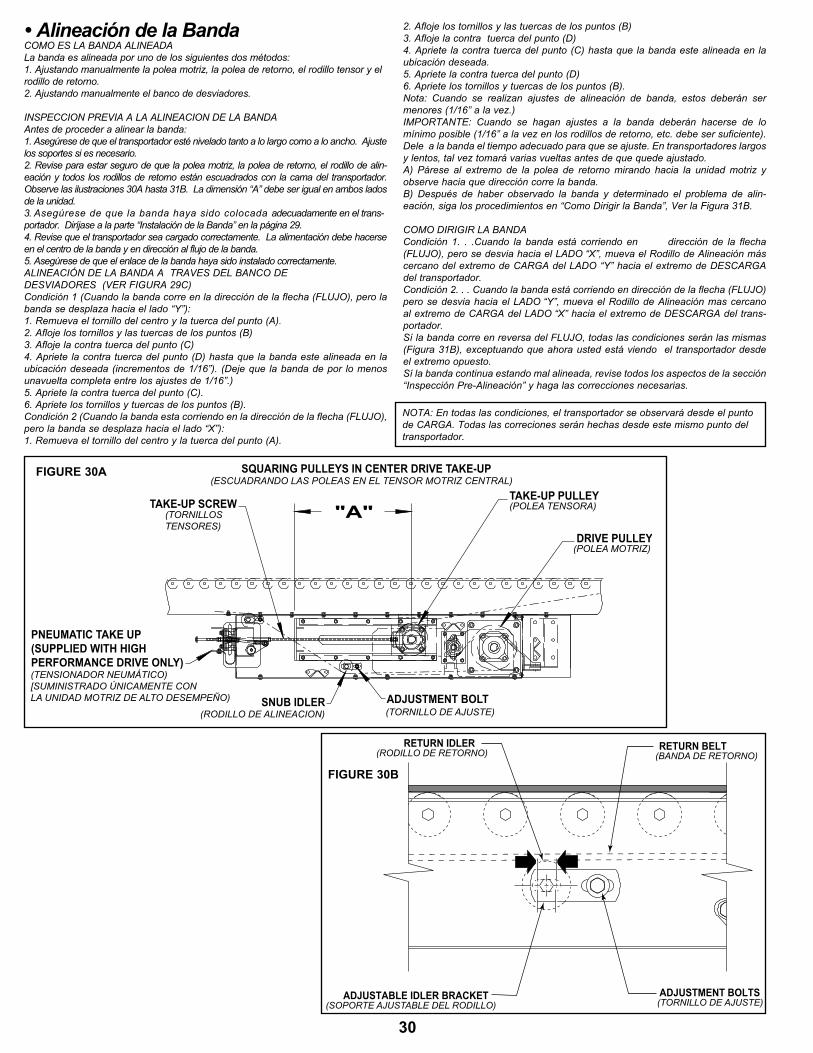
• Alineación de la BandaCOmO es la banda alIneadala banda es alineada por uno de los siguientes dos métodos:1 . ajustando manualmente la polea motriz, la polea de retorno, el rodillo tensor y el rodillo de retorno .2 . ajustando manualmente el banco de desviadores .
InspeCCIOn preVIa a la alIneaCIOn de la bandaantes de proceder a alinear la banda:1. Asegúrese de que el transportador esté nivelado tanto a lo largo como a lo ancho. Ajuste los soportes si es necesario .2 . revise para estar seguro de que la polea motriz, la polea de retorno, el rodillo de alin-eación y todos los rodillos de retorno están escuadrados con la cama del transportador . Observe las ilustraciones 30A hasta 31B. La dimensión “A” debe ser igual en ambos lados de la unidad . 3. Asegúrese de que la banda haya sido colocada adecuadamente en el trans-portador . diríjase a la parte “Instalación de la banda” en la página 29 .4. Revise que el transportador sea cargado correctamente. La alimentación debe hacerse en el centro de la banda y en dirección al flujo de la banda .5. Asegúrese de que el enlace de la banda haya sido instalado correctamente.alIneaCIón de la banda a traVes del banCO dedesVIadOres (Ver FIgUra 29C)Condición 1 (Cuando la banda corre en la dirección de la flecha (FLUJO), pero la banda se desplaza hacia el lado “Y”):1 . remueva el tornillo del centro y la tuerca del punto (a) .2 . afloje los tornillos y las tuercas de los puntos (b)3 . afloje la contra tuerca del punto (C)4. Apriete la contra tuerca del punto (D) hasta que la banda este alineada en la ubicación deseada (incrementos de 1/16”) . (deje que la banda de por lo menos unavuelta completa entre los ajustes de 1/16” .)5 . apriete la contra tuerca del punto (C) .6 . apriete los tornillos y tuercas de los puntos (b) .Condición 2 (Cuando la banda esta corriendo en la dirección de la flecha (FLUJO), pero la banda se desplaza hacia el lado “X”):1 . remueva el tornillo del centro y la tuerca del punto (a) .
2 . afloje los tornillos y las tuercas de los puntos (b)3 . afloje la contra tuerca del punto (d)4. Apriete la contra tuerca del punto (C) hasta que la banda este alineada en la ubicación deseada .5 . apriete la contra tuerca del punto (d)6 . apriete los tornillos y tuercas de los puntos (b) .nota: Cuando se realizan ajustes de alineación de banda, estos deberán ser menores (1/16” a la vez .)IMPORTANTE: Cuando se hagan ajustes a la banda deberán hacerse de lo mínimo posible (1/16” a la vez en los rodillos de retorno, etc . debe ser suficiente) .dele a la banda el tiempo adecuado para que se ajuste . en transportadores largos y lentos, tal vez tomará varias vueltas antes de que quede ajustado .A) Párese al extremo de la polea de retorno mirando hacia la unidad motriz y observe hacia que dirección corre la banda.B) Después de haber observado la banda y determinado el problema de alin-eación, siga los procedimientos en “Como dirigir la banda”, Ver la Figura 31b .
COmO dIrIgIr la bandaCondición 1. . .Cuando la banda está corriendo en dirección de la flecha (FLUJO), pero se desvia hacia el LADO “X”, mueva el Rodillo de Alineación más cercano del extremo de CARGA del LADO “Y” hacia el extremo de DESCARGA del transportador .Condición 2. . . Cuando la banda está corriendo en dirección de la flecha (FLUJO) pero se desvia hacia el LADO “Y”, mueva el Rodillo de Alineación mas cercano al extremo de CARGA del LADO “X” hacia el extremo de DESCARGA del trans-portador .sí la banda corre en reversa del FlUJO, todas las condiciones serán las mismas (Figura 31B), exceptuando que ahora usted está viendo el transportador desde el extremo opuesto .sí la banda continua estando mal alineada, revise todos los aspectos de la sección “Inspección Pre-Alineación” y haga las correcciones necesarias.
nOta: en todas las condiciones, el transportador se observará desde el punto de CARGA. Todas las correciones serán hechas desde este mismo punto del transportador .
TAKE-UP SCREWTAKE-UP PULLEY
DRIvE PULLEY
SNUB IDLER ADJUSTMENT BOLT
SQUARINg PULLEYS IN CENTER DRIvE TAKE-UP
(pOlea tensOra)
(esCUadrandO las pOleas en el tensOr mOtrIz Central)
(tOrnIllOstensOres)
(pOlea mOtrIz)
(rOdIllO de alIneaCIOn) (tOrnIllO de aJUste)
"A"
PNEUMATIC TAKE UP(SUPPLIED WITH HIGHPERFORMANCE DRIvE ONLY)(tensIOnadOr neUmÁtICO)[sUmInIstradO ÚnICamente COn la UnIdad mOtrIz de altO desempeÑO)
FIGURE 30A
RETURN IDLER(RODILLO DE RETORNO)
RETURN BELT(BANDA DE RETORNO)
ADJUSTMENT BOLTS(TORNILLO DE AJUSTE)
ADJUSTABLE IDLER BRACKET(SOPORTE AJUSTABLE DEL RODILLO)
FIGURE 30B
30
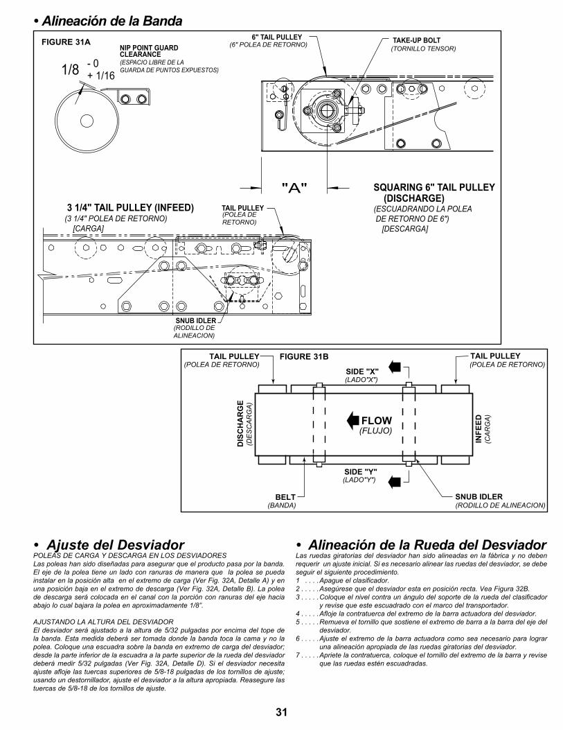
+ 1/16- 01/8
"A"
(3 1/4" pOlea de retOrnO) [Carga]
3 1/4" TAIL PULLEY (INFEED)
CLEARANCE(espaCIO lIbre de la gUarda de pUntOs eXpUestOs)
NIP POINT GUARD6" TAIL PULLEY TAKE-UP BOLT
(DISCHARGE)(esCUadrandO la pOlea de retOrnO de 6") [desCarga]
SQUARINg 6" TAIL PULLEY
(tOrnIllO tensOr)(6" pOlea de retOrnO)
TAIL PULLEY(pOlea deretOrnO)
SNUB IDLER(rOdIllO dealIneaCIOn)
FLOW
SIDE "X"
TAIL PULLEY
BELT SNUB IDLER
INFE
ED
DIS
CH
AR
GE
TAIL PULLEY
SIDE "Y"
(RODILLO DE ALINEACION)
(POLEA DE RETORNO)(POLEA DE RETORNO)
(LADO"Y")
(BANDA)
(LADO"X")
(FLUJO)
(CA
RG
A)
(DE
SC
AR
GA
)
FIGURE 31A
FIGURE 31B
• Alineación de la Banda
• Ajuste del DesviadorpOleas de Carga Y desCarga en lOs desVIadOresLas poleas han sido diseñadas para asegurar que el producto pasa por la banda. el eje de la polea tiene un lado con ranuras de manera que la polea se pueda instalar en la posición alta en el extremo de carga (Ver Fig . 32a, detalle a) y en una posición baja en el extremo de descarga (Ver Fig . 32a, detalle b) . la polea de descarga será colocada en el canal con la porción con ranuras del eje hacia abajo lo cual bajara la polea en aproximadamente 1/8” .
aJUstandO la altUra del desVIadOr el desviador será ajustado a la altura de 5/32 pulgadas por encima del tope de la banda . esta medida deberá ser tomada donde la banda toca la cama y no la polea . Coloque una escuadra sobre la banda en extremo de carga del desviador; desde la parte inferior de la escuadra a la parte superior de la rueda del desviador deberá medir 5/32 pulgadas (Ver Fig . 32a, detalle d) . si el desviador necesita ajuste afloje las tuercas superiores de 5/8-18 pulgadas de los tornillos de ajuste; usando un destornillador, ajuste el desviador a la altura apropiada . reasegure las tuercas de 5/8-18 de los tornillos de ajuste .
• Alineación de la Rueda del DesviadorLas ruedas giratorias del desviador han sido alineadas en la fábrica y no deben requerir un ajuste inicial . si es necesario alinear las ruedas del desviador, se debe seguir el siguiente procedimiento .1 . . . .apague el clasificador .2 . . . . .Asegúrese que el desviador esta en posición recta. Vea Figura 32B.3 . . . . .Coloque el nivel contra un ángulo del soporte de la rueda del clasificador
y revise que este escuadrado con el marco del transportador .4 . . . . .afloje la contratuerca del extremo de la barra actuadora del desviador .5 . . . . .remueva el tornillo que sostiene el extremo de barra a la barra del eje del
desviador .6 . . . . .ajuste el extremo de la barra actuadora como sea necesario para lograr
una alineación apropiada de las ruedas giratorias del desviador .7 . . . . .apriete la contratuerca, coloque el tornillo del extremo de la barra y revise
que las ruedas estén escuadradas .
31
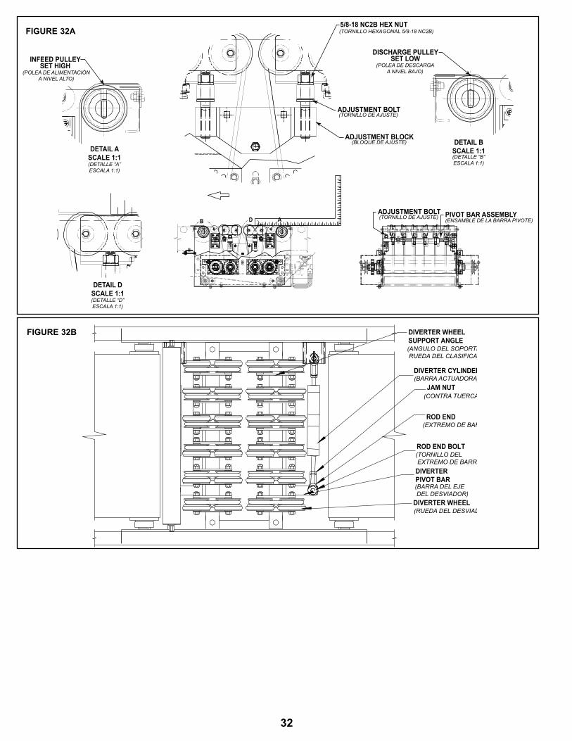
DETAIL ASCALE 1:1
5/8-18 NC2B HEX NUT
INFEED PULLEYSET HIGH
PIvOT BAR ASSEMBLYADJUSTMENT BOLT
(pOlea de alImentaCIóna nIVel altO)
(tOrnIllO HeXagOnal 5/8-18 nC2b)
(tOrnIllO de aJUste) (ensamble de la barra pIVOte)
(detalle “a”esCala 1:1)
ADJUSTMENT BOLT(tOrnIllO de aJUste)
ADJUSTMENT BLOCK(blOQUe de aJUste) DETAIL B
SCALE 1:1(detalle “b”esCala 1:1)
DISCHARGE PULLEYSET LOW
(pOlea de desCargaa nIVel baJO)
DETAIL DSCALE 1:1(detalle “d”esCala 1:1)
B D A
DIVERTER WHEEL
ROD END
JAM NUT
DIVERTER CYLINDER
PIVOT BARDIVERTER
ROD END BOLT
SUPPORT ANGLEDIVERTER WHEEL
(ANGULO DEL SOPORTE DE LA RUEDA DEL CLASIFICADOR)
(BARRA ACTUADORA)
(CONTRA TUERCA)
(EXTREMO DE BARRA)
(TORNILLO DEL EXTREMO DE BARRA)
(BARRA DEL EJE DEL DESVIADOR)
(RUEDA DEL DESVIADOR)
FIGURE 32A
FIGURE 32B
32
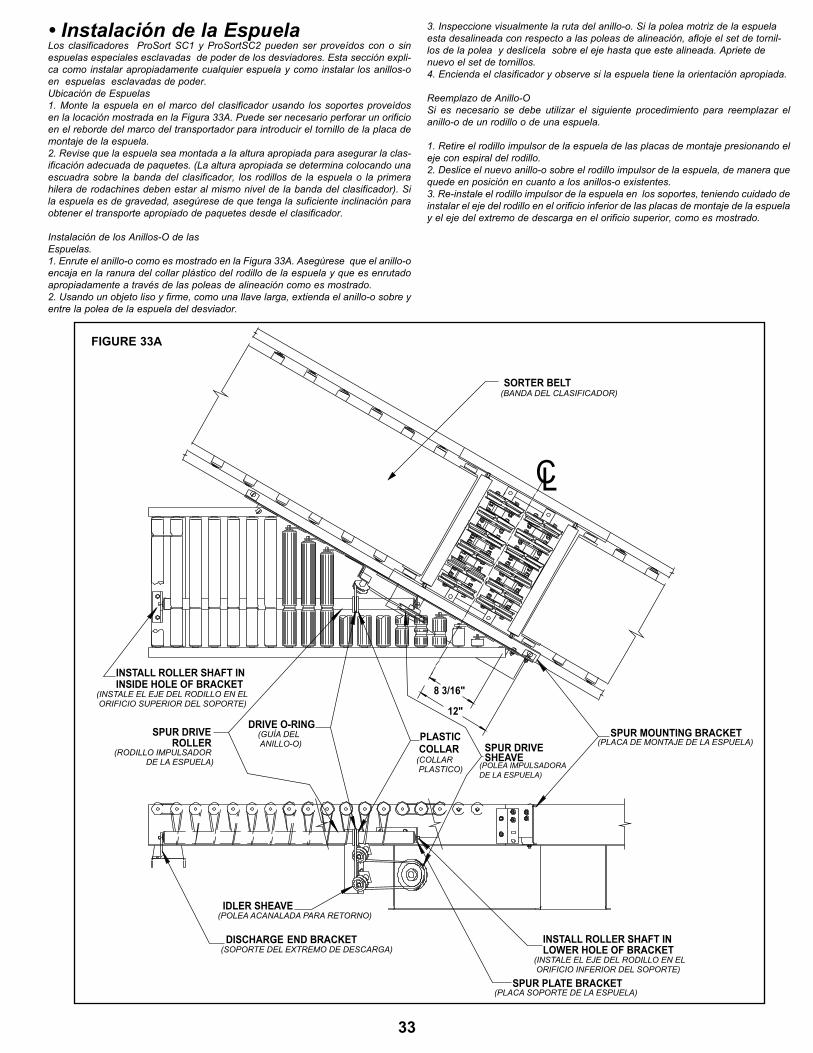
• Instalación de la Espuelalos clasificadores prosort sC1 y prosortsC2 pueden ser proveídos con o sin espuelas especiales esclavadas de poder de los desviadores . esta sección expli-ca como instalar apropiadamente cualquier espuela y como instalar los anillos-o en espuelas esclavadas de poder . Ubicación de espuelas1 . monte la espuela en el marco del clasificador usando los soportes proveídos en la locación mostrada en la Figura 33a . puede ser necesario perforar un orificio en el reborde del marco del transportador para introducir el tornillo de la placa de montaje de la espuela .2 . revise que la espuela sea montada a la altura apropiada para asegurar la clas-ificación adecuada de paquetes . (la altura apropiada se determina colocando una escuadra sobre la banda del clasificador, los rodillos de la espuela o la primera hilera de rodachines deben estar al mismo nivel de la banda del clasificador). Si la espuela es de gravedad, asegúrese de que tenga la suficiente inclinación para obtener el transporte apropiado de paquetes desde el clasificador .
Instalación de los anillos-O de lasespuelas .1. Enrute el anillo-o como es mostrado en la Figura 33A. Asegúrese que el anillo-o encaja en la ranura del collar plástico del rodillo de la espuela y que es enrutado apropiadamente a través de las poleas de alineación como es mostrado .2 . Usando un objeto liso y firme, como una llave larga, extienda el anillo-o sobre y entre la polea de la espuela del desviador .
3 . Inspeccione visualmente la ruta del anillo-o . si la polea motriz de la espuela esta desalineada con respecto a las poleas de alineación, afloje el set de tornil-los de la polea y deslícela sobre el eje hasta que este alineada. Apriete de nuevo el set de tornillos .4 . encienda el clasificador y observe si la espuela tiene la orientación apropiada .
reemplazo de anillo-O si es necesario se debe utilizar el siguiente procedimiento para reemplazar el anillo-o de un rodillo o de una espuela .
1 . retire el rodillo impulsor de la espuela de las placas de montaje presionando el eje con espiral del rodillo .2 . deslice el nuevo anillo-o sobre el rodillo impulsor de la espuela, de manera que quede en posición en cuanto a los anillos-o existentes . 3 . re-instale el rodillo impulsor de la espuela en los soportes, teniendo cuidado de instalar el eje del rodillo en el orificio inferior de las placas de montaje de la espuela y el eje del extremo de descarga en el orificio superior, como es mostrado .
12"
8 3/16"
END BRACKETDISCHARGE
SPUR PLATE BRACKET
INSIDE HOLE OF BRACKETINSTALL ROLLER SHAFT IN
LOWER HOLE OF BRACKETINSTALL ROLLER SHAFT IN
IDLER SHEAvE
SHEAvESPUR DRIvECOLLAR
PLASTICROLLERSPUR DRIvE
DRIvE O-RINgSPUR MOUNTING BRACKET
C
(plaCa de mOntaJe de la espUela)
(pOlea ImpUlsadOra de la espUela)
(gUÍa del anIllO-O)
(Instale el eJe del rOdIllO en el OrIFICIO sUperIOr del sOpOrte)
(rOdIllO ImpUlsadOr de la espUela)
(pOlea aCanalada para retOrnO)
(sOpOrte del eXtremO de desCarga)(Instale el eJe del rOdIllO en el OrIFICIO InFerIOr del sOpOrte)
(plaCa sOpOrte de la espUela)
(COllar plastICO)
L
SORTER BELT(banda del ClasIFICadOr)
FIGURE 33A
33

resOlVIendO prOblemas de transmIsIOn
prOblema CaUsa sOlUCIOn
el transportador no arranca o el motor se detiene frecuentemente .
1) el motor está sobrecargado .2) el motor pasa demasiada corriente .
1) Revise si hay sobrecarga del transportador.2) revise los circuitos e interruptores de protección y sobrecarga, y cámbielos si es
necesario .
desgaste excesivo de la cadena motriz .
1) la cadena está floja . 1) tensione la cadena .2) revise el tensionador neumático (ver abajo) .
Funcionamiento muy ruidoso .
1) rodamientos defectuosos . 1) reemplaze los rodamientos .
motor o reductor recalentado .
1) transportador está sobrecargado .2) bajo voltaje al motor .3) bajo nivel de lubricante en reductor .
1) revise la capacidad del transportador y reduzca la carga al nivel recomendado .2) Haga un chequeo por un electricista y corrija si es necesario.3) Vuelva a lubricar de acuerdo a las recomendaciones del fabricante .
la banda no se mueve, pero el motor corre .
1) el transportador está sobrecargado .2) la banda está floja .3) el revestimiento de la polea motriz esta gastada .
1) revise la capacidad del transportador y reduzca la carga al nivel recomendado .
2) Use tensores de banda para apretar la banda . revise el tensionador neumático (ver abajo) .
3) reemplaze la polea y apriete la banda .
las ruedas desviadoras no giran bajo condiciones de carga .
1) la unidad está sobrecargada2) el flujo de los paquetes están obstruidos por las guardas
laterales u otro objeto .
1) revise la capacidad del transportador y reduzca la carga al nivel recomendado .
2) libere la obstrucción .
el desviador es inoperable .
1) No hay presión de aire a los cilindros2) el solenoide está defectuoso
1) revise si la línea de aire está bloqueada o rota .2) reemplaze el solenoide .
tensionador neumático inoperante .
1) No hay presión de aire a la bolsa de aire.2) tensionador totalmente extendido .
1) revise si la línea de aire está bloqueada o rota .2) reestablezca el tensionador (ver tensión de la banda) .
el producto no es desviado .
1) altura del desviador desajustada .2) producto por fuera de las especificationes .
1) ajuste el desviador al al altura apropiada .2) remueva o ponga el producto en contenedor .
el producto rebota en los desviadores .
1) altura del desviador desajustada .2) producto por fuera de las especificationes .
1) ajuste el desviador al al altura apropiada .2) remueva o ponga el producto en contenedor .
resOlVIendO prOblemas de alIneaCIOn de la banda mOtrIz
prOblema CaUsa sOlUCIOn
la banda se desliza hacia un lado en la polea de retorno .
1) el rodillo de retorno o el rodillo de alineación cerca de la polea de retorno no están alineados o escuadrados con la cama .
1) ajuste como sea necesario . Vea “alineación de la banda” en este manual para detalles .
toda la banda se desliza hacia un lado.
1) El transportador no está derecho. 2) el transportador no está nivelado . 3) material acumulado en rodillos, poleas, o retornos .
1) realinie las secciones de cama como sea necesario . 2) Corrija como sea necesario . 3) remueva el residuo y aplique los limpiadores de banda o raspadores si es
posible .
• Resolviendo Problemas
34

35

Component(Componente)
Suggested Action(acción sugerida)
Schedule(Horario)
Weekly(semanal)
monthly(mensual)
Quarterly(trimestral)
motor
Check Noise (revisar el ruido)
Check Temperature (revisar la temperatura)
Check mounting Bolts (revisar los tornillos de montaje)
Reducer(reductor)
Check Noise (revisar el ruido)
Check Temperature (revisar la temperatura)
Check Oil Level (revisar el nivel de aceite)
Drive Chain(Cadena motriz)
Check Tension (revisar la tension)
Lubricate (lubricar)
Check for Wear (revisar el desgaste)
Sprockets(Catarinas)
Check for Wear (revisar el desgaste)
Check Set Screws & Keys (revisar los tornillos de fijación y prisioneros)
Bearings (Pulleys & Rollers)rodamientos (poleas & rodillos)
Check Noise (revisar el ruido)
Check mounting Bolts (revisar los tornillos de montaje)
V-Belts(bandas-V)
Check Tension (revisar la tension)
Check for Wear (revisar el desgaste)
Check Sheave Alignment (revisar la alineacion del eje de la polea)
Structural (estructura) General Check: All loose bolts, etc., tightened (revision general: tornillos sueltos, etc .)
• Planned Maintenance Checklist (Lista de Mantenimiento Preventivo) NOTA: REVISAR LOS TORNILLOS DE FIJACIÓN PARA OBTENER EL TORQUE ADECUADO
DESPUéS DE LAS PRIMERAS 24 HORAS DE OPERACIÓN.
Note: Check Set Screws for proper torque value after the first 24 hours of operation.
We know conveyor.
S Y S T E M S • S O L U T I O N S • S E R V I C E
( 8 7 0 ) 9 3 5 . 3 7 0 0
( 8 7 0 ) 9 3 1 . 1 8 7 7W W W. H Y T R O L . C O M
2020 HYTROL STREET
JONESBORO, ARKANSAS 72401
A : T :
F :W :


