maintenance information SHK-M-01-11 20130912 Flugzeugbau GmbH Kirchheim/Teck Maintenance information...
11
SCHEMPP-HIRTH Flugzeugbau GmbH Kirchheim/Teck Maintenance information SHK-M-01-11 for the flap control of Schempp-Hirth sailplanes and powered sailplanes page: 1 number of pages: 11 Kirchheim/Teck, 12.09.2013 Bearbeiter: J. Krauter I. General The flap setting bar must be checked routinely for proper function and maintained in working order. The flap control must move without excessive friction (allow for spring tension in some types and variants). The flap control must engage in each of the flap position indentations (or notches) so that it is impossible for the flap control to change positions by itself or unintentionally. Therefore there are 2 main issues to regard: 1. There should be no excessive wear on the corners of the flap position notches on the flap setting bar, and no excessive wear on the catch of the flap control (below the handle). 2. There should be sufficient spring tension on the flap control to force the catch into each of the flap position notches. The spring tension may be different for the various notches, but it must be ample in each position. In case it is doubtful whether or not the spring tension is sufficient, the force can be measured. When measuring, it is important to make sure that the catch is not rubbing on the front or back edge of the notch. Otherwise the measurement will read higher due to the re- sulting friction. This friction may be eliminated by partially disconnecting or disassem- bling the flap control, or by careful application or force on the trailing edge of the flap it- self on the assembled aircraft (requires a second person). The spring tension must be measured with a spring scale on the upper end of the flap control handle. The direction should be chosen so that the least amount of force is necessary to pull the catch away from the flap setting bar. The minimum allowable measurement for each model / series is given below. If the measurement is still influenced by friction even after taking the aforementioned steps, then the following actions can be taken: First, take the measurement following the steps given above. Then a second measurement is made starting from the non engaged position. Using the spring scale slowly let the catch slide into the notch. Take the force measurement at the moment the catch fully engages. The final measurement is the average of the first and second readings.
Transcript of maintenance information SHK-M-01-11 20130912 Flugzeugbau GmbH Kirchheim/Teck Maintenance information...

SCHEMPP-HIRTH Flugzeugbau GmbH Kirchheim/Teck
Maintenance information SHK-M-01-11 for the flap control of Schempp-Hirth sailplanes and powered sailplanes
page:
1
number of pages:
11
Kirchheim/Teck, 12.09.2013
Bearbeiter: J. Krauter
I. General
The flap setting bar must be checked routinely for proper function and maintained in working order. The flap control must move without excessive friction (allow for spring tension in some types and variants). The flap control must engage in each of the flap position indentations (or notches) so that it is impossible for the flap control to change positions by itself or unintentionally. Therefore there are 2 main issues to regard:
1. There should be no excessive wear on the corners of the flap position notches on the flap setting bar, and no excessive wear on the catch of the flap control (below the handle).
2. There should be sufficient spring tension on the flap control to force the catch into each of the flap position notches. The spring tension may be different for the various notches, but it must be ample in each position.
In case it is doubtful whether or not the spring tension is sufficient, the force can be measured. When measuring, it is important to make sure that the catch is not rubbing on the front or back edge of the notch. Otherwise the measurement will read higher due to the re-sulting friction. This friction may be eliminated by partially disconnecting or disassem-bling the flap control, or by careful application or force on the trailing edge of the flap it-self on the assembled aircraft (requires a second person). The spring tension must be measured with a spring scale on the upper end of the flap control handle. The direction should be chosen so that the least amount of force is necessary to pull the catch away from the flap setting bar. The minimum allowable measurement for each model / series is given below. If the measurement is still influenced by friction even after taking the aforementioned steps, then the following actions can be taken: First, take the measurement following the steps given above. Then a second measurement is made starting from the non engaged position. Using the spring scale slowly let the catch slide into the notch. Take the force measurement at the moment the catch fully engages. The final measurement is the average of the first and second readings.

SCHEMPP-HIRTH Flugzeugbau GmbH Kirchheim/Teck
Maintenance information SHK-M-01-11 for the flap control of Schempp-Hirth sailplanes and powered sailplanes
page:
2
number of pages:
11
Kirchheim/Teck, 12.09.2013
Bearbeiter: J. Krauter
II. Ventus-2c, Ventus-2cT, Ventus-2cM, Ventus-2cx (ÄB 349-32), Ventus-2cxa (ÄB 349-53), Ventus-2cxT (ÄB 825-44), Ventus-2cxM (ÄB 825-44), Ventus a, Ventus a 16.6, Ven-tus b, Ventus b 16.6, Ventus bT, Ventus aM, Ventus c, Ventus cT, Ventus cM, Mini Nimbus, Mini Nimbus B, Mini Nimbus C, Nimbus-2B, Nimbus-2C picture 1:
picture 2: picture 3:
In the picture shown, the flap control han-dle is fully engaged in one of the notched settings.
The outer sur-face of the bear-ing does not bear against the fork of the joint.
In this picture the flap control handle is not engaged in one of the notched settings.
The outer surface of the bearing bears against the inner wall of the joint fork and limits the rota-tion of the flap con-trol handle
(1)
(2)

SCHEMPP-HIRTH Flugzeugbau GmbH Kirchheim/Teck
Maintenance information SHK-M-01-11 for the flap control of Schempp-Hirth sailplanes and powered sailplanes
page:
3
number of pages:
11
Kirchheim/Teck, 12.09.2013
Bearbeiter: J. Krauter
a) Spring Tension Pictures 1 through 3 show the adjustment points for the relevant parts of the flap control in a Ventus-2cM (not after AB 825-44 (Ventus-2cM, Ventus-2cxT) or Ventus-2c not af-ter AB 349-32 (Ventus02cx)). The spring responsible for much of the force that pushes the flap control into a position locking notch can be seen in picture 2 running between the flap control tube and the main undercarriage box. The spring is directly attached to tube (2) and causes a twist-ing moment on the tube. This moment is transferred to the flap control tube, including the handle and latch, (1) over the bearing and fork joint. (see picture 1). The rear flap control rod (2) is connected at the rear with a bearing and fork joint to a swinging arm. When the flap control is fully engaged in a flap position, this outer bear-ing surface should not bear against the fork wall or otherwise have its movement hin-dered (see picture2). Otherwise the twisting moment caused by the spring would be reduced. When the flap control is disengaged from one of its position notches, the rotation dis-tance of the flap handle is limited by the outer surface of the bearing hitting the inner wall of the joint fork. (see picture 3) When the seat pan is installed, the rotation dis-tance of the flap handle is then limited by the small cut out in the seat pan. The description must be followed for every flap position. Otherwise the angle of the bearing head on either end of the tube (2) must be adjusted and relocked using the counter nut at the end of the tube. When measuring the spring tension on the flap handle, a minimum of 8 N should be reached. Somewhat higher values can easily be reached and make handling more comfortable. By rotating the spring fastening clamp on the flap control rod, the spring tension can be adjusted. However make sure that the spring is not over extended and the other end of the spring should be safely attached to the main undercarriage box b) Flap setting bar Pictures 4 and 5 show the difference between a new and worn flap setting bar. The new bar is shown on the left side of each picture. In picture 5, the rounded corners of the worn bar can be easily seen. Also the front and rear edges of each notch are no longer parallel so the notch is more trapezoidal instead of square shaped. Such a worn bar needs to be replaced. Besides the flap setting bar, the latch below the flap control handle needs to be in-spected for wear. The latch must have square surfaces and the corners should not be excessively rounded. Picture 6 shows an extremely worn latch that even has a groove worn into it. This example is far past the wear limit when a repair should have been made.

SCHEMPP-HIRTH Flugzeugbau GmbH Kirchheim/Teck
Maintenance information SHK-M-01-11 for the flap control of Schempp-Hirth sailplanes and powered sailplanes
page:
4
number of pages:
11
Kirchheim/Teck, 12.09.2013
Bearbeiter: J. Krauter
picture 4:
picture 5:

SCHEMPP-HIRTH Flugzeugbau GmbH Kirchheim/Teck
Maintenance information SHK-M-01-11 for the flap control of Schempp-Hirth sailplanes and powered sailplanes
page:
5
number of pages:
11
Kirchheim/Teck, 12.09.2013
Bearbeiter: J. Krauter
picture 6:
c) Flap handle With the Ventus b there was one case, where the flap handle broke from the flap actu-ating rod in the welding area. Therefore especially this area must be checked for dam-age like cracks, undue deformation or similar.
The pictures here in section II. come from a Ventus-2cM. The other models named in this section have the same or nearly the same flap control system shown in these pictures. The instructions given are useable for all models named.
For the Ventus-2cx (Ventus-2c after AB 349-32), Ventus-2cxT (Ventus-2cT after AB825-44) and Ventus-2cxM (Ventus-2cM after AB 825-44), the following must also be observed:
1. At the rotating arm (behind tube (2)), there is a spring installed that forces the
flap control tube strongly forward depending on the flap setting. Therefore, when measuring the spring force that keeps the flap control in its position notch as per section 1, this spring force should be considered. The best solu-tion would be to disconnect this spring when making the measurements.
2. The trim springs are relatively strong. Depending on the trim setting, control stick position and the flap position, the springs cause a twisting moment, like that of the spring attached to the main undercarriage box, that which very light-ly forces the latch into a flap setting notch. This moment is too small to keep the latch in its notch alone.

SCHEMPP-HIRTH Flugzeugbau GmbH Kirchheim/Teck
Maintenance information SHK-M-01-11 for the flap control of Schempp-Hirth sailplanes and powered sailplanes
page:
6
number of pages:
11
Kirchheim/Teck, 12.09.2013
Bearbeiter: J. Krauter
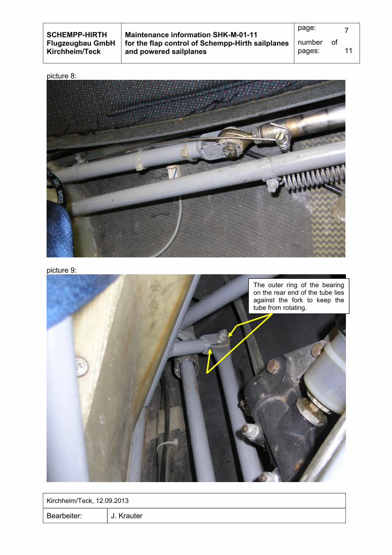
III. Nimbus-4, Nimbus-4T, Nimbus-4M, Nimbus-3, Nimbus-3T For these types and variants, everything concerning the flap control latch and the setting bar mentioned in section 2 is also useable. The spring tension that forces the latch into the position notch is generated differently. Simi-lar to section 2 there are tubes (1) and (2), see picture 7. A 2mm thick spring steel wire (pic-ture 8) connects between both tubes providing torsion. To adjust the tension, the spring wire is fixed in position on each tube using a hose clamp. The spring wire is not clamped directly on to the tube, but is fed between the tightening screw and the tension strap on each clamp. The aft end of tube (2) is attached to a swinging arm fork with a spherical bearing (picture 9). Because the spring is between tubes (1) and (2), only the front tube rotates when the flap control is disengaged from a notch position. The outer ring of the bearing on the rear end of tube (2) lies against the fork at all times, regardless of whether or not the flap handle is en-gaged in a position, thereby supporting the torsion moment of the spring. When measuring the spring tension on the end of the flap handle grip, a minimum force of 8 N must be reached.
picture 7:
(2)
(1)
Nimbus-4:
FLAP / AILERON INTERACTION TUBE
SCHEMPP-HIRTH Flugzeugbau GmbH Kirchheim/Teck
Maintenance information SHK-M-01-11 for the flap control of Schempp-Hirth sailplanes and powered sailplanes
page:
7
number of pages:
11
Kirchheim/Teck, 12.09.2013
Bearbeiter: J. Krauter
picture 8:
picture 9:
The outer ring of the bearing on the rear end of the tube lies against the fork to keep the tube from rotating.

SCHEMPP-HIRTH Flugzeugbau GmbH Kirchheim/Teck
Maintenance information SHK-M-01-11 for the flap control of Schempp-Hirth sailplanes and powered sailplanes
page:
8
number of pages:
11
Kirchheim/Teck, 12.09.2013
Bearbeiter: J. Krauter
IV. Janus, Janus B, Janus C, Janus CT, Janus CM, Nimbus-3D, Nimbus-3DT, Nimbus-3DM, Nimbus-4D, Nimbus-4DT, Nimbus-4DM, Nimbus-4DL, Nimbus-4DLT, Nimbus-4DLM, Arcus, Arcus T, Arcus M, Arcus E For these types and variants the flap handle is somewhat higher on the cockpit wall. The flap position plate is placed vertically. From experience, only after very high flight time does the plate wear to the point where it needs to be replaced. For this system, the latch should normally have a square profile shape. However, the front corners wear with time so that the latch is more or less rounded. As long as the sides of the latch lay flat against the walls of the notch when engaged, then this rounding is acceptable. Janus, Janus B, Janus C until S/N 238, Janus CT until S/N 6, Janus CM until S/N 29
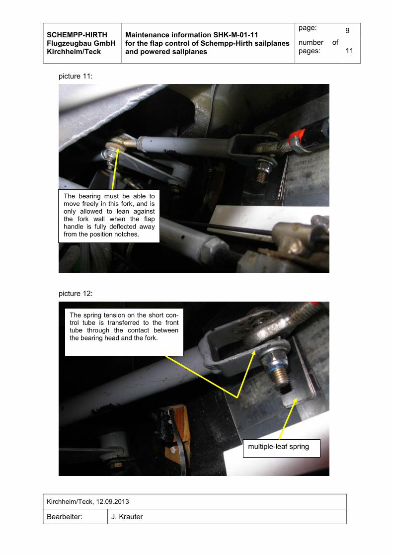
The spring tension forcing the latch into the position notch comes from a flat leaf spring screwed onto the short flap control tube behind the aft end of the cockpit side wall. The spring leaves lie against the inside surface of the fuselage skin. This area of the fuselage skin is covered with a piece of Mylar foil in order to reduce friction and wear. See pic-tures 10, 11 and 12. Keep in mind that on the flap control tube that sticks out from the back of the cockpit side wall, the outer bearing wall lies against the fork of the short tube, with the springs at-tached, at all times whether the flap handle latch is engaged or not. The bearing on the short tube connecting to the rotating arm further aft should not lean against the fork at all, or only when the flap handle is at its maximum deflection away from being engaged in a flap position notch. When the flap handle latch is engaged, the bearing must not lean against the fork wall at all. The force when measuring the spring tension on the top of the flap handle should be a minimum of 3 N.
picture 10:
Mylar sheet
2 short spring leafs
1 long spring leaf
SCHEMPP-HIRTH Flugzeugbau GmbH Kirchheim/Teck
Maintenance information SHK-M-01-11 for the flap control of Schempp-Hirth sailplanes and powered sailplanes
page:
9
number of pages:
11
Kirchheim/Teck, 12.09.2013
Bearbeiter: J. Krauter
picture 11:
picture 12:
The spring tension on the short con-trol tube is transferred to the front tube through the contact between the bearing head and the fork.
multiple-leaf spring
The bearing must be able to move freely in this fork, and is only allowed to lean against the fork wall when the flap handle is fully deflected away from the position notches.

SCHEMPP-HIRTH Flugzeugbau GmbH Kirchheim/Teck
Maintenance information SHK-M-01-11 for the flap control of Schempp-Hirth sailplanes and powered sailplanes
page:
10
number of pages:
11
Kirchheim/Teck, 12.09.2013
Bearbeiter: J. Krauter
Janus C ab Werk-Nr.239, Janus Ce, Janus CT ab Werk-Nr. 7, Janus CM ab Werk-Nr. 30, Nimbus-3D, Nimbus-3DT, Nimbus-3DM, Nimbus-4D, Nimbus-4DT, Nimbus-4DM, Nimbus-4DL/ Nimbus-4DLM mit Rumpfbau-Nr. 92:
The spring tension forcing the latch into the flap position notch is caused by a torsion spring behind the cockpit side wall in the rear seat area. The spring tension can deterio-rate if the spring weakens or fail completely if the spring breaks. In case the spring ten-sion is too weak, a leaf spring can be retrofitted with relative ease. In case the spring is broken and must be replaced, further instructions should be acquired. When measuring the spring tension at the top of the flap handle, a minimum force of 3 N should be reached.
Nimbus-4DL, Nimbus-4DLT, Nimbus-4DLM (ohne Nimbus-4DL/ Nimbus-4DLM mit Rumpf-bau-Nr. 92):
The spring tension forcing the latch into the flap position notch is caused by a torsion spi-ral spring between two flap control tubes just behind the rear end of the left cockpit wall, see picture 13. Similar to section III, the bearing head at the rear end of the flap control rod rests against the fork of rotating arm. The attachment bracket where the spring is connected to the forward rod can be rotated allowing the spring tension to be adjusted. When measuring the spring tension at the top of the flap handle, a minimum force of 4 N should be reached.
picture 13:
torsion spring
Controls in the fuselage
1. elevator control 2. aileron control 3. airbrake control 4. trim 5. flap control

SCHEMPP-HIRTH Flugzeugbau GmbH Kirchheim/Teck
Maintenance information SHK-M-01-11 for the flap control of Schempp-Hirth sailplanes and powered sailplanes
page:
11
number of pages:
11
Kirchheim/Teck, 12.09.2013
Bearbeiter: J. Krauter
Arcus, Arcus T, Arcus M, Arcus E:
The spring tension forcing the latch into the flap position notch is caused by a tension spi-ral spring, which pulls against a leverage arm on the short flap control tube just behind the end of the left cockpit wall, picture 14. Similar to the description for the Janus and Janus B in section IV the bearing head on the rear end of this control tube must have room to rotate freely. Especially when the flap control handle latch is fully engaged in any of the position notches, the bearing head should not be resting against the fork wall of the rotating arm. The bearing head in the rod in front of this rod is pinned to the rod and cannot be adjusted. A possibility to adjust the spring tension through changes in the linkage is not intended. If the spring tension is too weak, the spring should be replaced. When measuring the spring tension at the top of the flap handle, a minimum force of 4 N should be reached.
picture 14:
This bearing head is pinned to the rod and cannot be adjusted.