MAHATMA GANDHI MISSION’S JAWAHARLAL NEHRU …jnec.org/Lab-manuals/CIVIL/SE/C T LAB MANUAL...
54
JNEC CIVIL/CT/LGK/JUNE 2016 Page 1 MAHATMA GANDHI MISSION’S JAWAHARLAL NEHRU ENGINEERING COLLEGE, AURANGABAD. (M.S.) DEPARTMENT OF CIVIL ENGINEERING CONCRETE TECHNOLOGY LAB MANUAL Prepared By Approved By Prof. L. G. Kalurkar Dr. S. B. Shinde Lab In-charge H.O.D. CIVIL ENGG.
Transcript of MAHATMA GANDHI MISSION’S JAWAHARLAL NEHRU …jnec.org/Lab-manuals/CIVIL/SE/C T LAB MANUAL...

JNEC CIVIL/CT/LGK/JUNE 2016 Page 1
MAHATMA GANDHI MISSION’SJAWAHARLAL NEHRU ENGINEERING COLLEGE,
AURANGABAD. (M.S.)
DEPARTMENT OF CIVIL ENGINEERING
CONCRETE TECHNOLOGYLAB MANUAL
Prepared By Approved ByProf. L. G. Kalurkar Dr. S. B. ShindeLab In-charge H.O.D. CIVIL ENGG.
JNEC CIVIL/CT/LGK/JUNE 2016 Page 2
Vision of Civil Department
The department of Civil Engineering strives to produce qualified engineers, researchers and professionals to serve the society with sustainable development.
Mission of Civil Department
∑ To provide quality education and prepare competitive graduates for successful career in Civil Engineering.
∑ To develop research opportunities that creates competent professionals who are trained in the designand development of environment friendly Civil Engineering system.
Program Educational Objectives
1. Graduates of Civil Engineering Program will be prepared to take the challenges in the field of Civil Engineering.
2. To provide Graduates with a sound Knowledge in mathematical, scientific and Civil Engineering fundamentals required to solve engineering problems and also to pursue higher studies.
3. To train students with good scientific and engineering breadth in Construction industry & many field of Civil Engineering.
4. To build the confidence of students leading to professional and ethical integrity, effective communication skill, leadership, so that they can apply engineering knowledge for betterment of society.
5. To provide a good competitive learning environment so that graduates of Civil Engineering will be ready to meet the needs of Indian and multinational construction industries.
Program specific outcomes
The students are able to demonstrate:
1. The knowledge of planning and designing of the system components for building planning, transportation, water resources, estimating, costing and scheduling the construction processes.
2. The fundamental knowledge of analysis and design of various structures with an understanding of associated safety, quality and economy.
3. The knowledge of field data collection and material characterization to provide constructive and creative engineering solutions that reflect social and environmental sensitivities.

JNEC CIVIL/CT/LGK/JUNE 2016 Page 3
‘CONCRETE TECHNOLOGY’ EXPERIMENTSCLASS: - Second Year Civil Engineering
LIST OF EXPERIMENTS
Sr. No.
Name of Experiment Page No.
From To
I Testing of Cement
1 Fineness of cement. 3 3
2 Normal consistency of cement. 4 5
3 Initial and final setting times of cement. 6 8
4 Soundness of cement. 9 10
5 Compressive strength of cement. 11 13
II Testing of Fine & Course Aggregate
1 Water Absorption and moisture content of Aggregate.
14 16
2 Specific gravity and bulk density of coarse and fine Aggregates
17 18
3 Fineness modulus of fine and coarse aggregate (sieve analysis).
19 21
4 Flakiness index and elongation index of coarse aggregate.
22 25
5 Impact value and crushing value of aggregate. 26 31
III Concrete Mix Design by ACI and IS code method 32 36
IV Tests on Concrete
1 Workability tests- Slump cone test. 37 39
2 Compaction factor test. 40 42
3 Vee-bee consist-meter test. 43 45
V Strength tests on concrete
1 Compressive strength hardened concrete. 46 48
2 Splitting Tensile strength of hardened concrete. 49 51
Time Allotted for each Practical Session = 02 Hrs.

JNEC CIVIL/CT/LGK/JUNE 2016 Page 4
EXPERIMENT NO: I- FINENESS OF CEMENT
AIM: To determine the fineness of the given sample of cement by sieving.
APPARATUS: IS-90 micron sieve conforming to IS: 460-1965, standard balance, weights, brush.
INTRODUCTION:
The fineness of cement has an important bearing on the rate of hydration and hence on the rate of gain of strength and also on the rate of evolution of heat. Finer cement offers a greater surface area for hydration and hence the faster and greater the development of strength. Increase in fineness of cement is also found to increase the drying shrinkage of concrete. Fineness of cement is tested either by sieving or by determination of specific surface by air-permeability apparatus. Specific surface is the total surface area of all the particles in one gram of cement.
FINENESS BY SIEVING:
PROCEDURE:1. Weigh accurately 100 g of cement and place it on a standard 90 micron IS sieve. 2. Break down any air-set lumps in the cement sample with fingers. 3. Continuously sieve the sample giving circular and vertical motion for a period of 15 minutes. 4. Weigh the residue left on the sieve. As per IS code the percentage residue should not exceed 10%.
PRECAUTIONS:
Air set lumps in the cement sample are to be crushed using fingers and not to be pressed with the sieve. Sieving shall be done holding the sieve in both hands and with gentle wrist motion. More or less continuous rotation of the sieve shall be carried out throughout sieving.
OBSERVATIONS:
Sr. No. weigh of sample weight of residue(g) Fineness (%)taken(g)
123
Average fineness of cement =
RESULT: Fineness of given sample of cement =
CONCLUSION :

JNEC CIVIL/CT/LGK/JUNE 2016 Page 5
Figure: vicat apparatus for normal consistency of cement

JNEC CIVIL/CT/LGK/JUNE 2016 Page 6
EXPERIMENT NO: II- NORMAL ( STANDERED ) CONSISTENCY OF CEMENT
AIM: To determine the quantity of water required to produce a cement paste of standardconsistency.
APPARATUS: Vicat apparatus with plunger (10 mm in diameter) balance, weights, gauging trowel.
INTRODUCTION: The standard consistency of a cement paste is defined as that consistency which will permit the vicat plunger to penetrate to a point 5 to 7 mm from the bottom of the vicat mould. For finding out initial setting time, final setting time, soundness of cement and compressive strength of cement, it is necessary to fix the quantity of water to be mixed in cement in each case. This experiment is intended to find out the quantity of water to be mixed for a given cement to give a cement paste of normal consistency and can be done with the help of vicat apparatus.
PROCEDURE:
1. Prepare a paste of weighed quantity of cement (300 grams) with a weighed quantity of potable or distilled water, starting with 26% water of 300g of cement.
2. Take care that the time of gauging is not less than 3 minutes, not more than 5 minutes and the gauging shall be completed before setting occurs.
3. The gauging time shall be counted from the time of adding the water to the dry cement until commencing to fill the mould.
4. Fill the vicat mould with this paste, the mould resting upon a non porous plate. 5. After completely filling the mould, trim off the surface of the paste, making it in level with the top of the
mould. The mould may slightly be shaken to expel the air. 6. Place the test block with the mould, together with the non-porous resting plate, under the rod bearing the
plunger (10mm diameter), lower the plunger gently to touch the surface of the test block and quickly release, allowing it to penetrate into the paste.
7. This operation shall be carried out immediately after filling the mould. 8. Prepare trial pastes with varying percentages of water and test as described above until the amount of water
necessary for making the standard consistency as defined above is obtained. 9. Express the amount of water as a percentage by weight of the dry cement.
PRECAUTIONS:
Clean appliances shall be used for gauging. In filling the mould the operator hands and the blade of the gauging trowel shall alone be used. The temperature of cement, water and that of test room, at the time when the above operations are being performed, shall be 27 + 2 C. For each repetition of the experiment fresh cement is to be taken.
OBSERVATIONS:
Weight of cement Weight of water PlungerTime
Consistency of
S. No taken in gms taken in gms penetration cement in % byTaken
(a) (b) (mm) weight b/a * 100123
RESULT: Normal consistency for the given sample of cement is……….

JNEC CIVIL/CT/LGK/JUNE 2016 Page 7
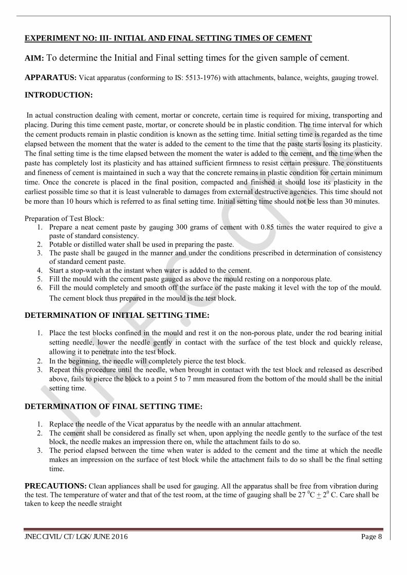
Figure: vicat apparatus for the initial and final setting times of cement
JNEC CIVIL/CT/LGK/JUNE 2016 Page 8
EXPERIMENT NO: III- INITIAL AND FINAL SETTING TIMES OF CEMENT
AIM: To determine the Initial and Final setting times for the given sample of cement.
APPARATUS: Vicat apparatus (conforming to IS: 5513-1976) with attachments, balance, weights, gauging trowel.
INTRODUCTION:
In actual construction dealing with cement, mortar or concrete, certain time is required for mixing, transporting and placing. During this time cement paste, mortar, or concrete should be in plastic condition. The time interval for which the cement products remain in plastic condition is known as the setting time. Initial setting time is regarded as the time elapsed between the moment that the water is added to the cement to the time that the paste starts losing its plasticity. The final setting time is the time elapsed between the moment the water is added to the cement, and the time when the paste has completely lost its plasticity and has attained sufficient firmness to resist certain pressure. The constituents and fineness of cement is maintained in such a way that the concrete remains in plastic condition for certain minimum time. Once the concrete is placed in the final position, compacted and finished it should lose its plasticity in the earliest possible time so that it is least vulnerable to damages from external destructive agencies. This time should not be more than 10 hours which is referred to as final setting time. Initial setting time should not be less than 30 minutes.
Preparation of Test Block:1. Prepare a neat cement paste by gauging 300 grams of cement with 0.85 times the water required to give a
paste of standard consistency. 2. Potable or distilled water shall be used in preparing the paste. 3. The paste shall be gauged in the manner and under the conditions prescribed in determination of consistency
of standard cement paste. 4. Start a stop-watch at the instant when water is added to the cement. 5. Fill the mould with the cement paste gauged as above the mould resting on a nonporous plate. 6. Fill the mould completely and smooth off the surface of the paste making it level with the top of the mould.
The cement block thus prepared in the mould is the test block.
DETERMINATION OF INITIAL SETTING TIME:
1. Place the test blocks confined in the mould and rest it on the non-porous plate, under the rod bearing initial setting needle, lower the needle gently in contact with the surface of the test block and quickly release, allowing it to penetrate into the test block.
2. In the beginning, the needle will completely pierce the test block. 3. Repeat this procedure until the needle, when brought in contact with the test block and released as described
above, fails to pierce the block to a point 5 to 7 mm measured from the bottom of the mould shall be the initial setting time.
DETERMINATION OF FINAL SETTING TIME:
1. Replace the needle of the Vicat apparatus by the needle with an annular attachment. 2. The cement shall be considered as finally set when, upon applying the needle gently to the surface of the test
block, the needle makes an impression there on, while the attachment fails to do so. 3. The period elapsed between the time when water is added to the cement and the time at which the needle
makes an impression on the surface of test block while the attachment fails to do so shall be the final setting time.
PRECAUTIONS: Clean appliances shall be used for gauging. All the apparatus shall be free from vibration during the test. The temperature of water and that of the test room, at the time of gauging shall be 27 0C + 20 C. Care shall be taken to keep the needle straight

JNEC CIVIL/CT/LGK/JUNE 2016 Page 9
OBSERVATIONS:
Time in minutes =
Height in mm fails to penetrate=
RESULT:
Initial setting time for the given sample of cement =
Final setting time for the given sample of cement =

JNEC CIVIL/CT/LGK/JUNE 2016 Page 10
Figure: Le Chatelier Mould
Figure: Le Chatelier apparatus for soundness of cement

JNEC CIVIL/CT/LGK/JUNE 2016 Page 11
EXPERIMENT NO: III- SOUNDNESS OF CEMENT
AIM: To determine the soundness of the given sample of cement by "Le Chatelier" Method.
APPARATUS: Le -Chatelier apparatus conforming to IS 5514-1969, Balance, Weights, Water bath.
INTRODUCTION:
It is essential that the cement concrete shall not undergo appreciable change in volume after setting. This is ensured by limiting the quantities of free lime, magnesia and sulphates in cement which are the causes of the change in volume known as unsoundness. Unsoundness in cement does not come to surface for a considerable period of time. This test is designed to accelerate the slaking process by the application of heat and discovering the defects in a short time. Unsoundness produces cracks, distortion and disintegration there by giving passage to water and atmospheric gases which may have injurious effects on concrete and reinforcement.The apparatus for conducting the test consists of small split cylinder of spring brass or other suitable metal of 0.5mm thickness forming a mould 30 mm internal diameter and 30mm high. On either side of the split mould are attached to indicators with pointed ends, the distance from these ends to the center of the cylinder being 165 mm. The mould shall be kept in good condition with the jaws not more than 50mm apart.
PROCEDURE:
1. Place the lightly oiled mould on a lightly oiled glass sheet and fill it with cement paste formed by gauging cement with 0.78 times the water required to give a paste of standard consistency.
2. The paste shall be gauged in the manner and under the conditions prescribed in determination of consistency of standard cement paste, taking care to keep the edges of the mould gently together
3. While this operation is being performed cover the mould with another piece of glass sheet, place a small weight on this covering glass sheet and immediately submerge the whole assembly in water at a temperature of 27 0 - 20 C and keep there for 24 hours.
4. Measure the distance separating the indicator points. 5. Submerge the moulds again in water at the temperature prescribed above. 6. Bring the water to boiling, with the mould kept submerged for 25 to 30 minutes, and keep it boiling for three
hours. 7. Remove the mould from the water allow it to cool and measure the distance between the indicator points. 8. The difference between these two measurements represents the expansion of the cement. 9. For good quality cement this expansion should not be more than 10mm.
OBSERVATIONS:
Initial distance between the indicator points in mm =Final distance between the indicator points in mm = Expansion in mm = final length - initial length =
RESULT: Expansion in mm …….
CONCLUSION: The given sample of cement is ………. (sound/unsound)

JNEC CIVIL/CT/LGK/JUNE 2016 Page 12
Figure: Compressive Strength Testing machine

JNEC CIVIL/CT/LGK/JUNE 2016 Page 13
EXPERIMENT NO: IV-COMPRESSIVE STRENGTH OF CEMENT
AIM: To determine the compressive strength of standard cement mortar cubes compacted bymeans of standard vibration machine.
APPARATUS: Vibration machine and cube moulds of size 7.06 cms (Conforming to IS: 4031-1988)
STANDARD SAND: The standard sand to be used in the test shall conform to IS: 650-1991 or sand passing 100 percent through 2 mm sieve and retained 100 percent on 90 micron IS sieve.
2mm to 1mm 33.33 percent1mm to 500 microns 33.33 percent500mm to 90 microns 33.33 percent.
INTRODUCTION:
The compressive strength of cement mortars is determined in order to verify whether the cement conforms to IS specifications and whether it will be able to develop the required compressive strength of concrete. The average compressive strength of at least three mortar cubes (area of the face 50 cm2 ) composed of one part of cement and three parts of standard stand should satisfy IS code specifications.
PROCEDURE:
Mix proportions and mixing:1. Clean appliances shall be used for mixing and the temperature of the water and that of the test room at the
time when the above operations are being performed shall be 27 + 2oC.
2. Place in a container a mixture of cement and standard sand in the proportion of 1:3 by weight mix it dry, with a trowel for one minute and then with water until the mixture is of uniform color.
3. The quantity of water to be used shall be as specified below. 4. In any element, it should not take more than 4 minutes to obtain uniform colored mix.
5. If it exceeds 4 minutes the mixture shall be rejected and the operation repeated with a fresh quantity of cement, sand and water.
6. The material for each cube shall be mixed separately and the quantity of cement standard
sand and water shall be as follows:Cement 200 gmsStandard sand 600 grms ( 200gm+ 200gm + 200gm )Water (P/4 + 3.0) percent of combined weight of cement and
sand, where p is the percentage of water required to produce a paste of standard consistency.
MOULDING SPECIMENS:
1. In assembling the moulds ready for use, cover the joints between the halves of the mould with a thin film of petroleum jelly and apply a similar coating of petroleum jelly between the contact surfaces of the bottom of the mould and its base plate in order to ensure that no water escapes during vibration.
2. Treat the interior faces of the mould with a thin coating of mould oil. 3. Place the assembled mould on the table of the vibration machine and firmly hold it is position by means of
suitable clamps. 4. Securely attach a hopper of suitable size and shape at the top of the mould to facilitate filling and this hopper
shall not be removed until completion of the vibration period.
5. Immediately after mixing the mortar, place the mortar in the cube mould and rod with a rod. 6. The mortar shall be rodded 20 times in about 8 seconds to ensure elimination of entrained air and honey

JNEC CIVIL/CT/LGK/JUNE 2016 Page 14
combing. 7. Place the remaining quantity of mortar in the hopper of the cube mould and rod again as specified for the first
layer and then compact the mortar by vibrations.
8. The period of vibration shall be two minutes at the specified speed of 12,000 + 400 vibrations per minute.
9. At the end of vibration remove the mould together with the base plate from the machine and finish the top surface of the cube in the mould by smoothing surface with the blade of a trowel.
CURING SPECIMEN:
1. Keep the filled moulds at a temperature of 27 + 20 C in an atmosphere of at least 90 % relative humidity for about 24 hours after completion of vibration.
2. At the end of that period remove them from the moulds. 3. Immediately submerge in clean fresh water and keep them under water until testing.
4. The water in which the cubes are submerged shall be renewed every 7 days and shall be maintained at a temperature of 27 0C + 20C.
5. After they have been taken out and until they are tested the cubes shall not be allowed to become dry.
TESTING:
1. Test three cubes for compressive strength at the periods mentioned under the relevant specification for different hydraulic cements, the periods being reckoned from the completion of vibration.
2. The compressive strength shall be the average of the strengths of three cubes for each period of curing. 3. The cubes shall be tested on their sides without any packing between the cube and the steel platens of the
testing machine. 4. One of the platens shall be carried base and shall be self adjusting and the load shall be
steadily and uniformly applied starting from zero at a rate of 350 Kgs/cm2/ min. The cubes are tested at the following periods
Ordinary portland cement 3, 7 and 28 days.Rapid hardening portland cement 1 and 3 days.Low heat portland cement 3 and 7 days.
CALCULATION:
Calculate the compressive strength from the crushing load and the average area over which the load is applied. Express the results in N/mm2 to the nearest 0.05 mm2.Compressive strength in N/mm2 = P/A =
Where P is the crushing load in N and A is the area in mm2 (5000 mm2)
PRECAUTIONS: Inside of the cube moulds should be oiled to prevent the mortar from adhering to the sides of the mould.
RESULT: The average compressive strength of the given cement
at 3 days =__________N/mm2
at 7 days =__________N/mm2
at 28 days =_________N/mm2

JNEC CIVIL/CT/LGK/JUNE 2016 Page 15
Figure: specific gravity fine aggregate by pycnometer method (apparatus).

JNEC CIVIL/CT/LGK/JUNE 2016 Page 16
EXPERIMENT NO: V- (A) DETERMINATION OF SPECIFIC GRAVITY OF FINE AGGREGATE
AIM: To determine specific gravity of a given sample of fine aggregate.
APPARATUS-: Pycnometer, A 1000-ml measuring cylinder, well-ventilated oven, Taping rod,
Filter papers and funnel, etc.
PROCEDURE:
1. A sample of about 500 g shall be placed in the tray and covered with distilled water at a
temperature of 22 to 32°C. Soon after immersion, air entrapped in or bubbles on the surface of
the aggregate shall be removed by gentle agitation with a rod. The sample shall remain
immersed for 24 ± l/2 hours.
2. The water shall then be carefully drained from the sample, by decantation through a filter
paper, any material retained being return& to the sample. The fine aggregate including any
solid matter retained on the filter paper shall be exposed to a gentle current of warm air to
evaporate surface moisture and the material just attains a ‗free-running‘ condition. The
saturated and surface-dry sample shall be weighed (weight A).
3. The aggregate shall then be placed in the pycnometer which shall be filled with distilled water.
Any trapped air shall be eliminated by rotating the pycnometer on its side, the hole in the apex
of the cone being covered with a finger. The pycnometer shall be dried on the outside and
weighed (weight B).
4. The contents of the pycnometer shall be emptied into the tray, care being taken to ensure that all the aggregate is transferred. The pycnometer shall be refilled with distilled water to the same level as
before , dried on the outside and weighed (weight C).
5. The water shall then be carefully drained from the sample by decantation through a filter paper
and any material retained returned to the sample. The sample shall be placed in the oven in the
tray at a temperature of 100 to 110°C for 24 f l/2 hours, during which period it shall be stirred
occasionally to facilitate drying. It shall be cooled in the air-tight container and weighed
(weight D).
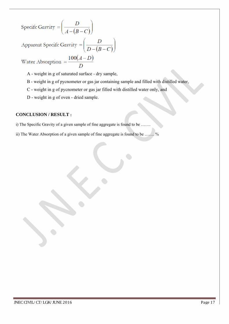
CALCULATIONS:Specific gravity, apparent specific gravity and water &sorption shall be calculated as follows:
JNEC CIVIL/CT/LGK/JUNE 2016 Page 17
A - weight in g of saturated surface - dry sample,
B - weight in g of pycnometer or gas jar containing sample and filled with distilled water,
C - weight in g of pycnometer or gas jar filled with distilled water only, and
D - weight in g of oven - dried sample.
CONCLUSION / RESULT :
i) The Specific Gravity of a given sample of fine aggregate is found to be …….
ii) The Water Absorption of a given sample of fine aggregate is found to be ……. %

JNEC CIVIL/CT/LGK/JUNE 2016 Page 18
Figure: Specific gravity fine aggregate by wire basket (apparatus).

JNEC CIVIL/CT/LGK/JUNE 2016 Page 19
EXPERIMENT NO: V-(B) DETERMINATION OF SPECIFIC GRAVITY OF COARSE AGGREGATE
AIM: To determine Specific Gravity of a given sample of course aggregate.
APPARATUS:A wire basket of not more than 6-3 mm mesh, A stout watertight container in which the basket may be freely suspended, well-ventilated oven, Taping rod, An airtight container of capacity similar to that of the
PROCEDURE:1. A sample of not less than 2000 g of the aggregate shall be thoroughly washed to remove finer particles
and dust, drained and then placed in the wire basket and immersed in distilled water at a temperature between 22°C to 32°C with a cover of at least 5 cm of water above the top of the basket.
2. Immediately. after immersion the entrapped air shall be removed from the sample by lifting the basket containing it 25 mm above the base of the tank and allowing it to drop 25 times at the rate of about one drop per second. The basket and aggregate shall remain completely immersed during the operation and for a period of 24 ± l/2 hours afterwards.
3. The basket and the sample shall then be jolted and weighed in water at a temperature of 22°C to 32°C (weight A1).
4. The basket and the aggregate shall then be removed from the water and allowed to drain for a few minutes, after which the, aggregate shall be gently emptied from the basket on to one of the dry clothes, and the empty basket shall be returned to the water and weighed in water ( weight A2 ).
5. The aggregate placed on the dry cloth shall be gently surface dried with the cloth, transferring it to the second dry cloth when the first will remove no further moisture. The aggregate shall then be weighed (weight B).
6. The aggregate shall then be placed in the oven in the shallow tray, at a temperature of 100 to 110°C and maintained at this temperature for 24 ± l/2 hours. It shall then be removed from the oven, cooled in the airtight container and weighed (weight C).
CALCULATIONS:Specific gravity, apparent specific gravity and water &sorption shall be calculated asfollows:
A - 1 - A2 )B - Weight of the saturated surface - dry aggregate in airC - Weight of oven dried aggregate in air.A1-Weight of aggregate and basket in waterA2- Weight of empty basket in water
CONCLUSION / RESULT :
i) The Specific Gravity of a given sample of course aggregate is found to be …….
ii) The Water Absorption of a given sample of course aggregate is found to be ……. %

JNEC CIVIL/CT/LGK/JUNE 2016 Page 20
Figure: Sieve Analysis apparatus.

JNEC CIVIL/CT/LGK/JUNE 2016 Page 21
EXPERIMENT NO: VI- FINENESS MODULUS OF FINE AND COARSE AGGREGATE
AIM: To determine the fineness modulus of given fine and coarse aggregates.
APPARATUS: IS test sieves, square hole perforated plate 75mm, 40mm, 20mm, 10mm, and fine wire cloth of 4800, 2400, 1200, 600, 300, and 150 Microns. Weighing balance (Sensitivity 0.1 percent) sieve shaker, tray plates.
INTRODUCTION:Fine aggregate is sand used in mortars. Coarse aggregate is broken stone used in concrete. The size of the fine aggregate is limited to maximum 4.75 mm (4800 microns) beyond which it is known as coarse aggregate. Fineness modulus is only a numerical index of fineness, giving some idea about, the mean size of the particles in the entirebody of concrete. Determination of fineness modulus is considered as a method of standardization of grading of aggregates i.e. the main object of finding fineness modulus is to grade the given aggregate for the most economical mix and workability with minimum quantity of cement. It is obtained by sieving known weight of given aggregate in a set of standard sieves and by adding the percent weight of material retained on all the sieves and dividing the total percentage by 100.
PROCEDURE:Coarse aggregate:
1. Take 5Kgs of coarse aggregate (nominal size 20mm) from the sample by quartering. 2. Carry out sieving by hand, shake each sieve in order 75mm ,40mm, 20mm, 10mm, and No's 480, 240, 120,
60, 30, & 15 over a clean dry tray for a period of not less than 2 minutes. 3. The shaking is done with a varied motion backward and forward, left to right, circular, clockwise and
anticlockwise and with frequent jarring. 4. So that material is kept moving over the sieve surface in frequently changing directions. 5. Find the weight retained on each sieve taken in order
Fine aggregate:
1. Take 1 Kg of sand from sample by quartering in clean dry plate. 2. Arrange the sieves in order of No. 480, 240, 120, 60, 30 and 15 keeping sieve 480 at top
and 15 at bottom.3. Fix them in the sieve shaking machine with the pan at the bottom and cover at the top. 4. Keep the sand in the top sieve no 480, carry out the sieving in the set of sieves and arranged before for not
less than 10 minutes. 5. Find the weight retained in each sieve.
OBSERVATIONS:Coarse aggregate: Wt. of coarse aggregate taken: …….. Kgs.
Sr.No Sieve size Weight retained
%weight retained
%weight passing
Cumulative % weight retained
1. 75 mm2. 40mm3. 20 mm4. 10 mm5. 4800 mm6. 2400 mm7. 1200 mm8. 600 mm9. 300mm10. 150mm
Fine aggregate: Wt. of fine aggregate taken: Kgs

JNEC CIVIL/CT/LGK/JUNE 2016 Page 22
Weight % Weight % weightCumulative
S.No Sieve size % Weightsretained retained passing
retained1 4800 microns2 2400 microns3 1200 microns4 600 microns5 300 microns6 150 microns
Fineness Modulus: Sum of Cumulative percentage Wt. retained /100
PRECAUTIONS:
1. The sample should be taken by quartering. 2. The sieving must be done carefully to prevent the spilling of aggregate.
REQUIREMENTS: Limits of fineness modulus of aggregates.
RESULT:
The fineness modulus of given fine aggregate :……..
The fineness modulus of given coarse aggregate……….
CONCLUSION:

JNEC CIVIL/CT/LGK/JUNE 2016 Page 23
Figure: Flakiness index apparatus
Figure: Elongation index apparatus

JNEC CIVIL/CT/LGK/JUNE 2016 Page 24
EXPERIMENT NO: VII- DETERMINATION OF FLAKINESS INDEX AND ELONGATION INDEX OF COURSE AGGREGATES
AIM: To Determination of Flakiness Index and Elongation Index of Course Aggregates.
APPARATUS: The metal gauge shall be of the pattern shown in Fig. 10.1, Balance, Gauging Trowel, Stop Watch, etc.
INTRODUCTION:
Particle shape and surface texture influence the properties of freshly mixed concrete more than the properties of hardened concrete. Rough-textured, angular, and elongated particles require more water to produce workable concrete than smooth, rounded compact aggregate. Consequently, the cement content must also be increased to maintain the water-cement ratio. Generally, flat and elongated particles are avoided or are limited to about 15 % by weight of the total aggregate.
PROCEDURE :
1. Sample - A quantity of aggregate shall be taken sufficient to provide the minimum number of 200 pieces of any fraction to be tested.2. Sieving - The sample shall be sieved in accordance with the method described in Exp. 3(b) with the sieves specified in Table 3.18
3. Separation of Flaky material- Each fraction shall be gauged in turn for thickness on a metal gauge of the pattern shown in Fig. 11.1, or in bulk on sieves having elongated slots. The width of the slot used in the gauge or sieve shall be of the dimensions specified in co1 3 of Table 3.18 for the appropriate size of material.
4. Weighing of Flaky Material - The total amount passing the gauge shall be weighed to an accuracy of at least 0.1 percent of the weight of the test sample.
5. The flakiness index is the total weight of the material passing the various thickness gauges or sieves, expressed as a percentage of the total weight of the sample gauged.
6. Sieving - The sample shall be sieved in accordance with the method described in Exp. 3(b) with the sieves specified in Table 3.18.
7. Separation of Elongated Material- Each fraction shall be gauged individually for length on a metal length gauge of the pattern shown in Fig. 11.2. The gauge length used shall be that specified in co1 4 of Table 3.18 for the appropriate size of material.
8. Weighing of Elongated Material - The total amount retained by the length gauge shall be weighed to an

JNEC CIVIL/CT/LGK/JUNE 2016 Page 25
accuracy of at least 0.1 percent of the weight of the test sample. 9. The elongation index is the total weight of the material retained on the various length gauges, expressed
as a percentage of the total weight of the sample gauged.OBSERVATION : 1. Total weight of course aggregate. . . . . . . g (Flakiness Index)
2.Total weight of course aggregate. . . . . . . g (Elongation Index)
Size of Aggregate ThicknessLength Gauge
Weight Percentage of
Retained on Weight Retained RemarkPassing through Retained on
mm
IS Sieves IS SievesLength Gauge (%)
63 mm 50 mm --
50 mm 40 mm 81.0
40 mm 25 mm 58.5
Size of Aggregate ThicknessWeight
Percentage of
Thickness Gauge Retained onWeight Retained Remark
Passing through Retained onmm Thickness
IS Sieves IS Sieves(%)
Gauge
63 mm 50 mm 33.90
50 mm 40 mm 27.00
40 mm 25 mm 19.60
31 mm 25 mm 16.95
25 mm 20 mm 13.50
20 mm 16 mm 10.80
16 mm 12 mm 8.55
12.5 mm 10 mm 6.75
10 mm 6.3 mm 4.89
Total

JNEC CIVIL/CT/LGK/JUNE 2016 Page 26
31 mm 25 mm --
25 mm 20 mm 40.5
20 mm 16 mm 32.4
16 mm 12 mm 25.6
12.5 mm 10 mm 20.2
10 mm 6.3 mm 14.7
Total
CALCULATION : Total % of retained on thickness gauge (%)
The Flakiness index on an aggregate is = 100
Total % of retained on length gauge (%)The elongation index on an aggregate is = 100
CONCLUSION / RESULT:
i) The flakiness index of a given sample of fine aggregate is ………. %
ii)The elongation index of a given sample of fine aggregate is ……..%

JNEC CIVIL/CT/LGK/JUNE 2016 Page 27
Figure: Aggregate impact test machine
JNEC CIVIL/CT/LGK/JUNE 2016 Page 28
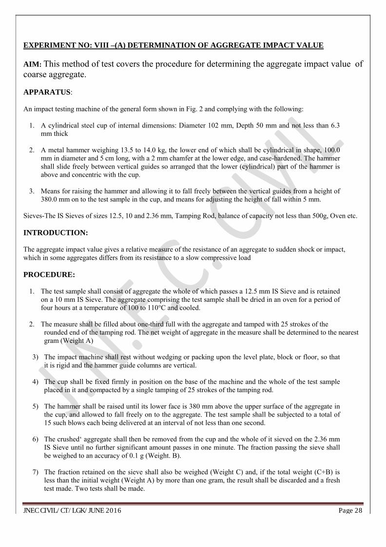
EXPERIMENT NO: VIII –(A) DETERMINATION OF AGGREGATE IMPACT VALUE
AIM: This method of test covers the procedure for determining the aggregate impact value of coarse aggregate.
APPARATUS:
An impact testing machine of the general form shown in Fig. 2 and complying with the following:
1. A cylindrical steel cup of internal dimensions: Diameter 102 mm, Depth 50 mm and not less than 6.3 mm thick
2. A metal hammer weighing 13.5 to 14.0 kg, the lower end of which shall be cylindrical in shape, 100.0 mm in diameter and 5 cm long, with a 2 mm chamfer at the lower edge, and case-hardened. The hammer shall slide freely between vertical guides so arranged that the lower (cylindrical) part of the hammer is above and concentric with the cup.
3. Means for raising the hammer and allowing it to fall freely between the vertical guides from a height of 380.0 mm on to the test sample in the cup, and means for adjusting the height of fall within 5 mm.
Sieves-The IS Sieves of sizes 12.5, 10 and 2.36 mm, Tamping Rod, balance of capacity not less than 500g, Oven etc.
INTRODUCTION:
The aggregate impact value gives a relative measure of the resistance of an aggregate to sudden shock or impact, which in some aggregates differs from its resistance to a slow compressive load
PROCEDURE:
1. The test sample shall consist of aggregate the whole of which passes a 12.5 mm IS Sieve and is retained on a 10 mm IS Sieve. The aggregate comprising the test sample shall be dried in an oven for a period of four hours at a temperature of 100 to 110°C and cooled.
2. The measure shall be filled about one-third full with the aggregate and tamped with 25 strokes of the rounded end of the tamping rod. The net weight of aggregate in the measure shall be determined to the nearest gram (Weight A)
3) The impact machine shall rest without wedging or packing upon the level plate, block or floor, so that it is rigid and the hammer guide columns are vertical.
4) The cup shall be fixed firmly in position on the base of the machine and the whole of the test sample placed in it and compacted by a single tamping of 25 strokes of the tamping rod.
5) The hammer shall be raised until its lower face is 380 mm above the upper surface of the aggregate in the cup, and allowed to fall freely on to the aggregate. The test sample shall be subjected to a total of 15 such blows each being delivered at an interval of not less than one second.
6) The crushed‘ aggregate shall then be removed from the cup and the whole of it sieved on the 2.36 mm IS Sieve until no further significant amount passes in one minute. The fraction passing the sieve shall be weighed to an accuracy of 0.1 g (Weight. B).
7) The fraction retained on the sieve shall also be weighed (Weight C) and, if the total weight (C+B) is less than the initial weight (Weight A) by more than one gram, the result shall be discarded and a fresh test made. Two tests shall be made.

JNEC CIVIL/CT/LGK/JUNE 2016 Page 29
CALCULATION:
The ratio of the weight of fines formed to the total sample weight in each test shall he expressed as a percentage, the result being recorded to the first decimal place:
A - weight in gm of saturated surface - dry sample,
B -weight in gm of fraction passing through 2.36 mm IS Sieves
CONCLUSION / RESULT :
The aggregate Impact value of given sample of coarse aggregate is ……….. %
The aggregate impact value should not be more than 45 per cent for aggregate used for concrete other than for wearing surfaces, and 30 per cent for concrete used for wearing surfaces such a runways, roads and air field pavements.

JNEC CIVIL/CT/LGK/JUNE 2016 Page 30

JNEC CIVIL/CT/LGK/JUNE 2016 Page 31
EXPERIMENT NO: VIII –(B) DETERMINATION OF AGGREGATE CRUSHING VALUE
AIM: This method of test covers the procedure for determining the aggregate crushing value.
APPARATUS:
A 15-cm diameter open-ended steel cylinder, with plunger and base-plate, of the general form and dimensions shown in Fig.A straight metal tamping rod, A balance of capacity 3 kg, readable and accurate to one gram, IS Sieves of sizes 12.5, 10 and 2.36 mm, For measuring the sample, cylindrical metal measure of sufficient rigidity to retain its form under rough usage and of the following internal dimensions: Diameter 11.5 cm and Height 18.0 cm
THEORY :
The ‗aggregate crushing value‘ gives a relative measure of the resistance of an aggregate to crushing under a gradually applied compressive load. With aggregate of ‗aggregate crushing value‘ 30 or higher, the result may be anomalous, and in such cases the ‗ten percent fines value‘ should be determined instead.
PROCEDURE:
1. The material for the standard test shall consist of aggregate passing a 12.5 mm IS Sieve and retained on a 10 mm IS Sieve, and shall be thoroughly separated on these sieves before testing.
2. The aggregate shall be tested in a surface-dry condition. If dried by heating, the period of drying shall not exceed four hours, the temperature shall be 100 to 110°C and the aggregate shall be cooled to not exceed four hours, the temperature shall be 100 to 110°C and the aggregate shall be cooled to room temperature before testing.
3. The appropriate quantity may be found conveniently by filling the cylindrical measure in three layers of approximately equal depth, each layer being tamped 25 times with the rounded end of the tamping rod and finally leveled off, using the tamping rod as a straight-edge.
4. The weight of material comprising the test sample shall be determined (Weight A) and the same weight of sample shall be taken for the repeat test.
5. The apparatus, with the test sample and plunger in position, shall then be placed between the platens of the testing machine and loaded at as uniform a rate as possible so that the total load is reached in 10 minutes. The total load shall be 400 kN.
6. The load shall be released and the whole of the material removed from the cylinder and sieved on a 2.36 mm IS Sieve for the standard test. The fraction passing the sieve shall be weighed (Weight B).
CALCULATION:
The ratio of the weight of fines formed to the total sample weight in each test shall be expressed as a percentage, the result being recorded to the first decimal place:
A -weight in gm of saturated surface - dry sample,
JNEC CIVIL/CT/LGK/JUNE 2016 Page 32
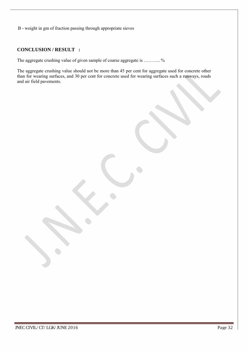
B - weight in gm of fraction passing through appropriate sieves
CONCLUSION / RESULT :
The aggregate crushing value of given sample of coarse aggregate is ……….. %
The aggregate crushing value should not be more than 45 per cent for aggregate used for concrete other than for wearing surfaces, and 30 per cent for concrete used for wearing surfaces such a runways, roads and air field pavements.

JNEC CIVIL/CT/LGK/JUNE 2016 Page 33
EXPERIMENT NO: IX –CONCRETE MIX DESIGN BY ACI COMMITTEE 211.1 OF 1991 METHOD
AIM: To determine the concrete mix proportion by American Concrete Institute Method of Mix Design.
THEORY :Data to be collected : (i) Fineness modulus of selected F.A. (ii) Unit weight of dry rodded coarse aggregate. (iii) Sp. gravity of coarse and fine aggregates in SSD condition (iv) Absorption characteristics of both coarse and fine aggregates. (v) Specific gravity of cement
APPARATUS : : (1) Concrete mixer, (2) Balance, (3) Molds (or forms) for casting of the test specimens for future testing.
PROCEDURE :
1. From the minimum strength specified, estimate the average design strength either by using standard deviation or by using coefficient of variation.
The mean strength, fm = f min + ks
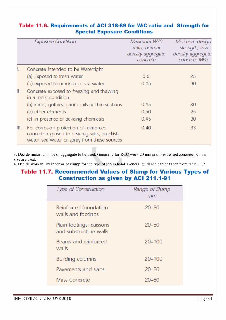
2. Find the water/cement ratio from the strength point of view from Table 11.5. Find also the water/ cement ratio from durability point of view from Table 11.6. Adopt lower value out of strength consideration and durability consideration
JNEC CIVIL/CT/LGK/JUNE 2016 Page 34
3. Decide maximum size of aggregate to be used. Generally for RCC work 20 mm and prestressed concrete 10 mm size are used. 4. Decide workability in terms of slump for the type of job in hand. General guidance can be taken from table 11.7

JNEC CIVIL/CT/LGK/JUNE 2016 Page 35
5. The total water in kg/m3 of concrete is read from table 11.8 entering the table with the selected slump and selected maximum size of aggregate. Table 11.8 also gives the approximate amount of accidentally entrapped air in non-air-entrained concrete
6. Cement content is computed by dividing the total water content by the water/cement ratio. 7. From table 11.4 the bulk volume of dry rodded coarse aggregate per unit volume of concrete is selected, for the particular maximum size of coarse aggregate and fineness modulus of fine aggregate.

JNEC CIVIL/CT/LGK/JUNE 2016 Page 36
8. The weight of C.A. per cubic meter of concrete is calculated by multiplying the bulk volume with bulk density
9. From Table 11.9, the first estimate of density of fresh concrete for 20 mm maximum size of aggregate and for non-air-entrained concrete
10. The solid volume of coarse aggregate in one cubic meter of concrete is calculated by knowing the specific gravity of C.A. 11. Similarly the solid volume of cement, water and volume of air is calculated in one cubic meter of concrete. 12. The solid volume of sand is computed by subtracting from the total volume of concrete the solid volume of cement, coarse aggregate, water and entrapped air.

JNEC CIVIL/CT/LGK/JUNE 2016 Page 37
13. Wight of fine aggregate is calculated by multiplying the solid volume of fine aggregate by specific gravity of F.A.
RESULT/ CONCLUSION : :
Final Mix Proportion by American Concrete Institute Method of Mix Design (ACI Committee 211.1 of 1991) Method

JNEC CIVIL/CT/LGK/JUNE 2016 Page 38
EXPERIMENT NO: X –
TO DETERMINE THE WORKABILITY OF FRESH CONCRETE BY SLUMP CONE TEST

JNEC CIVIL/CT/LGK/JUNE 2016 Page 39
Figure: Slump Cone Apparatus
AIM: To Determine the Workability of Fresh Concrete By Slump Cone Test.
INTRODUCTION: The word workability or workable concrete signifies much wider and deeper meaning than
the other terminology consistency often used loosely for workability. Consistency is a general term to indicate the
degree of fluidity or the degree of mobility

JNEC CIVIL/CT/LGK/JUNE 2016 Page 40
The factors helping concrete to have more lubricating effect to reduce internal friction for helping easy compaction are given below:
(a) Water Content (b) Mix Proportions (c) Size of Aggregates (d) Shape of Aggregates (e) Surface Texture of Aggregate (f) Grading of Aggregate (g) Use of Admixtures.
DESCRIPTION: Slump test is the most commonly used method of measuring consistency of concrete which can be employed either in laboratory or at site of work. It is not a suitable method for very wet or very dry concrete. It does not measure all factors contributing to workability, nor is it always representative of the placability of the concrete. The pattern of slump is shown in Fig. It indicates the characteristic of concrete in addition to the slump value. If the concrete slumps evenly it is called true slump. If one half of the cone slides down, it is called shear slump. In case of a shear slump, the slump value is measured as the difference in height between the height of the mould and the average value of the subsidence. .
APPARATUS: The Slump Cone apparatus for conducting the slump test essentially consists of a metallic mould in the form of a frustum of a cone having the internal dimensions as under: Bottom diameter : 20 cm, Top diameter : 10 cm, Height : 30 cm and the thickness of the metallic sheet for the mould should not be thinner than 1.6 mm Weights and weighing device, Tamper ( 16 mm in diameter and 600 mm length), Ruler, Tools and containers for mixing, or concrete mixer etc.
MATERIALS: Cement, sand, coarse aggregate, water. Concrete mix-1:2:4, w/c ratio -0.5 or 0.6
PROCEDURE:
1. Dampen the mold and place it on a flat, moist, nonabsorbent (rigid) surface. It shall be held firmly in place during filling by the operator standing on the two foot pieces. Immediately fill the mold in three layers, each approximately one third the volume of the mold.
2. Rod each layer with 25 strokes of the tamping rod. Uniformly distribute the strokes over the cross section of each layer.
3. In filling and rodding the top layer, heap the concrete above the mold before rodding start. If the rodding operation results in subsidence of the concrete below the top edge of the mold, add additional concrete to keep an excess of concrete above the top of the mold at all time.
4. After the top layer has been rodded, strike off the surface of the concrete by means of screeding and rolling motion of the tamping rod.
5. Remove the mold immediately from the concrete by raising it carefully in the vertical direction. Raise the mold a distance of 300 mm in 5 ± 2 sec by a steady upward lift with no lateral or torsional motion.
6. Immediately measure the slump by determining the vertical difference between top of the mold and the displaces original center of the top surface of the specimen. Complete the entire test from the start of the filling through removal of the mold without interruption and complete it within 2½ min.
7. If a decided falling away or shearing off of concrete from one side or portion of the mass occurs, disregard the test and make a new test on another portion of the sample. If two consecutive tests on a sample of concrete show a falling away or shearing off of a portion of concrete from the mass of specimen, the concrete lacks necessary plasticity and cohesiveness for the slump test to be applicable.
8. After completion of the test, the sample may be used for casting of the specimens for the future testing
OBSERVATION:

JNEC CIVIL/CT/LGK/JUNE 2016 Page 41
X1 = Height of mould = 300 mm
X2 = Height of mould subsided Concrete = ……..mm
X = Slump of Concrete = X1 -X2
RESULT:-The slump of concrete is……….. mm
CONCLUSION:-
1. The slump of concrete ………..mm indicate Low/ Medium/ High Degree of workability.
2. The pattern of slump is shown …………(True Slump/Shear Slump/ Collapse Slump).
EXPERIMENT NO: XI –
TO DETERMINE THE WORKABILITY OF FRESH CONCRETE BY COMPACTION FACTOR TEST

JNEC CIVIL/CT/LGK/JUNE 2016 Page 42
Figure: Compaction Factor Test Apparatus.
AIM: To Determine the Workability of Fresh Concrete By compacting factor Test.

JNEC CIVIL/CT/LGK/JUNE 2016 Page 43
DESCRIPTION: Compacting Factor Test: The compacting factor test is designed primarily for use in the laboratory but it can also be used in the field. It is more precise and sensitive than the slump test and is particularly useful for concrete mixes of very low workability as are normally used when concrete is to be compacted by vibration. The method applies to plain and air-entrained concrete, made with lightweight, normal weight or heavy aggregates having a nominal maximum size of 40 mm or less but not to aerated concrete or no-fines concrete.
APPARATUS: Compacting Factor Apparatus, Trowel, Scoop about 150 mm long., Balance capable of weighing up to 25 kg with the sensibility of 10 g. Weights and weighing device, Tamper ( 16 mm in diameter and 600 mm length), Ruler, Tools and containers for mixing, or concrete mixer .
MATERIALS: Cement, sand, coarse aggregate, water. Concrete mix-1:2:4, w/c ratio -0.5 or 0.6
PROCEDURE:
1. The internal surface of the hoppers and cylinder shall be thoroughly clean and free from superfluous moisture and any set of concrete commencing the test.
2. The sample of concrete to be tested shall be placed gently in the upper hopper using the scoop. The trap door shall be opened immediately after filling or approximately 6 min after water is added so that the concrete fails into the lower hopper. During this process the cylinder shall be covered.
3. Immediately after the concrete has come to the rest the cylinder shall be uncovered, the trap door of the lower hopper opened and the concrete allowed falling to into the cylinder.
4. For some mixes have a tendency to stick in one or both of the hoppers. If this occurs the concrete shall be helped through by pushing the tamping rod gently into the concrete from the top.
5. The excess of concrete remaining above the level of the top of the cylinder shall then be cut off by holding a trowel in each hand, with the plane of the blades horizontal, and moving them simultaneously one from each side across the top of the cylinder, at the same time keeping them pressed on the top edge of the cylinder. The outside of the cylinder shall then be wiped clean. This entire process shall be carried out at a place free from vibration or shock.
6. Determine the weight of concrete to the nearest 10 g. This is known as "weight of partially compacted concrete", Wp.
7. Refill the cylinder with concrete from the same sample in layers approximately 50 mm depth. The layers being heavily rammed with the compacting rod or vibrated to obtain full compaction. The top surface of the fully compacted concrete shall be carefully struck off and finished level with the top of the cylinder. Clean up the outside of the cylinder.
8. Determine the weight of concrete to the nearest 10 g. This is known as "weight of fully compacted concrete", Wf.
9. The compacting factor, Fc can be calculated as follows:
The compacting factor = “wt. of partially compacted concrete.”Wp.“wt. of fully compacted concrete.”Wf.
OBSERVATION :
The compacting factor is defined as the ratio of the weight of partially compacted concrete to the weight of fully compacted concrete. It shall normally be stated to the nearest second decimal place.
OBSERVATION TABLE:
Sr.

JNEC CIVIL/CT/LGK/JUNE 2016 Page 44
No Description Sample 1 Sample 2 Sample 3
1Weight of Empty Cylinder (W1)
2Weight of Cylinder + Free Fall Concrete (W2)
3Weight of Cylinder + Hand Compacted Concrete (W2)
4Weight of Partially Compacted Concrete (Wp=W2-W1)
5Weight of Fully Compacted Concrete (Wf=W2-W1)
6The Compacting Factor
=Wp/Wf
REQUIREMENTS:
Sr. No. Workability compaction factor
1 Very low 0.75 To 0.80
2 Low 0.80 To 0.85
3 Medium 0.85 To 0.92
4 High Above 0.92
CONCLUSION:
1. As the compaction factor of given sample of concrete is …….
2. The Workability of concrete is…………..(very low/low/ medium/high)
JNEC CIVIL/CT/LGK/JUNE 2016 Page 45
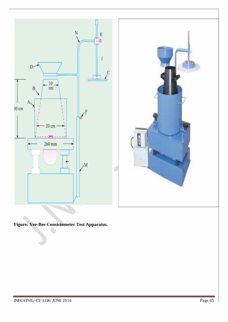
Figure: Vee-Bee Consistometer Test Apparatus.

JNEC CIVIL/CT/LGK/JUNE 2016 Page 46
EXPERIMENT NO: XII –
TO DETERMINE THE CONSISTENCY OF CONCRETE BY VEE-BEE CONSISTOMETER METHOD
AIM: To Determine the consistency of concrete using a Vee-Bee Consistometer, which determines the time required for transforming, by vibration, a concrete specimen in the shape of a conical frustum into a cylinder
DESCRIPTION: Vee Bee Consistometer Test: This is a good laboratory test to measure indirectly the workability of concrete. This test consists of a vibrating table, a metal pot, a sheet metal cone, a standard iron rod.
The vibrator table (C) is 380 mm long and 260 mm wide and is supported on rubber shock absorbers at a height of about 305 mm above floor level. The table is mounted on a base (K) which rests on three rubber feet and is equipped with an electrically operated vibrometer mounted under it, operating on either 65 or 220 volts three phase, 50 cycles alternating current. A sheet metal cone (B) open at both ends is placed in the metal pot (A) and the metal pot is fixed on to the vibrator table by means of two wing-nuts (H). The sheet metal cone is 30 cm high and its bottom diameter is 20 cm and top diameter 10 cm. A swivel arm holder (M) is fixed to the base and, into this is telescoped another swivel arm (N) with funnel (D) and guide-sleeve (E). The swivel arm can be readily detached from the vibrator table. The graduated rod (J) is fixed on to the swivel arm and at the end of the graduated arm ‗8. glass disc records the slump of concrete after rod is 20 mm in (C) is screwed .The division of the scale on the rod bf the concrete cone in centimetres and the volume vibration of the cone in the pot.The standard iron diameter and 500 mm in length.
APPARATUS:
Vee Bee Consistometer : a) A vibrator table resting upon elastic supports, b) A metal pot, c) A sheet metal cone, open at both ends, and d) A standard iron rod. Weights and weighing device, Tamper ( 16 mm in diameter and 600 mm length), Ruler, Tools and containers for mixing, or concrete mixer etc.
MATERIALS: Cement, sand, coarse aggregate, water.
PROCEDURE:
1. Slump test as described earlier is performed, placing the slump cone inside the sheet metal cylindrical pot of the consistometer.
2. The glass disc attached to the swivel arm is turned and placed on the top of the concrete in the pot. The electrical vibrator is then switched on and simultaneously a stop watch started.
3. The vibration is continued till such a time as the conical shape of the concrete disappears and the concrete assumes a cylindrical shape. This can be judged by observing the glass disc from the top for disappearance of transparency.
4. Immediately when the concrete fully assumes a cylindrical shape, the stop watch is switched off. The time required for the shape of concrete to change from slump cone shape to cylindrical shape in seconds is known as Vee Bee Degree.
5. This method is very suitable for very dry concrete whose slump value cannot be measured by Slump Test, but the vibration is too vigorous for concrete with a slump greater than about 50 mm.

JNEC CIVIL/CT/LGK/JUNE 2016 Page 47
OBSERVATION : :
1. The time required for the shape of concrete to change from slump cone shape to cylindrical shape in seconds is known as Vee Bee Degree
OBSERVATION TABLE:
Sr. No Initial reading T1 in sec Final reading T2 in sec Vee-bee degrees in sec
1
2
3
CONCLUSION:
1. The Workability of concrete is……vee -bee degrees.

JNEC CIVIL/CT/LGK/JUNE 2016 Page 48
EXPERIMENT NO: XIII –
TO DETERMINE COMPRESSIVE STRENGTH OF CUBIC CONCRETE SPECIMENS
Figure: Compressive Strength Testing machine.

JNEC CIVIL/CT/LGK/JUNE 2016 Page 49
AIM: To determine the compressive strength of cubic concrete specimens. It consists of applying a compressive axial load to molded cubes at a rate which is within a prescribed range until failure occurs.
DESCRIPTION: Age at Test - Tests shall be made at recognized ages of the test specimens, the most usual being 7 and 28 days. Where it may be necessary to obtain the early strengths, tests may be made at the ages of 24 hours ± ½ hour and 72 hours ± 2 hours. The ages shall be calculated from the time of the addition of water to the dry ingredients.
Number of Specimens - At least three specimens, preferably from different batches, shall be made for testing at each selected age.
.
APPARATUS:
Testing Machine - The testing machine may be of any reliable type, of sufficient capacity for the tests and capable of applying the load at the rate specified in 5.5. The permissible error shall be not greater than ± 2 percent of the maximum load.
Cube Moulds - The mould shall be of 150 mm size conforming to IS: 10086-1982.
Cylinders -The cylindrical mould shall be of 150 mm diameter and 300 mm height conforming to IS: 10086-1982. Weights and weighing device, Tools and containers for mixing, Tamper (square in cross section) etc
MATERIALS: Cement, sand, coarse aggregate, water. Concrete mix-1:2:4, w/c ratio -0.5 or 0.6
PROCEDURE:
1. Sampling of Materials - Samples of aggregates for each batch of concrete shall be of the desired grading and shall be in an air-dried condition. The cement samples, on arrival at the laboratory, shall be thoroughly mixed dry either by hand or in a suitable mixer in such a manner as to ensure the greatest possible blending and uniformity in the material.
2. Proportioning - The proportions of the materials, including water, in concrete mixes used for determining the suitability of the materials available, shall be similar in all respects to those to be employed in the work.
3. Weighing - The quantities of cement, each size of aggregate, and water for each batch shall be determined by weight, to an accuracy of 0.1 percent of the total weight of the batch.
4. Mixing Concrete - The concrete shall be mixed by hand, or preferably, in a laboratory batch mixer, in such a manner as to avoid loss of water or other materials. Each batch of concrete shall be of such a size as to leave about 10 percent excess after moulding the desired number of test specimens.
5. Mould - Test specimens cubical in shape shall be 15 × 15 × 15 cm. If the largest nominal size of the aggregate does not exceed 2 cm, 10 cm cubes may be used as an alternative. Cylindrical test specimens shall have a length equal to twice the diameter.
6. Compacting - The test specimens shall be made as soon as practicable after mixing, and in such a way as to produce full compaction of the concrete with neither segregation nor excessive laitance.
7. Curing - The test specimens shall be stored in a place, free from vibration, in moist air of at least 90 percent relative humidity and at a temperature of 27° ± 2°C for 24 hours ± ½ hour from the time of addition of water to the dry ingredients
8. Placing the Specimen in the Testing Machine - The bearing surfaces of the testing machine shall be wiped clean and any loose sand or other material removed from the surfaces of the specimen which are to be in contact with the compression platens.

JNEC CIVIL/CT/LGK/JUNE 2016 Page 50
9. In the case of cubes, the specimen shall be placed in the machine in such a manner that the load shall be applied to opposite sides of the cubes as cast, that is, not to the top and bottom.
10. The axis of the specimen shall be carefully aligned with the centre of thrust of the spherically seated platen. No packing shall be used between the faces of the test specimen and the steel platen of the testing machine.
11. The load shall be applied without shock and increased continuously at a rate of approximately 140 kg/sq cm/min until the resistance of the specimen to the increasing load breaks down and no greater load can be sustained.
12. The maximum load applied to the specimen shall then be recorded and the appearance of the concrete and any unusual features in the type of failure shall be noted.
OBSERVATION :
1. Mix proportions 1:2:4.2. w/c ratio -0.63. Date of casting:4. Size of cube: -15cmX15cmX15cm.5. Area of cube:-150mmX150mm =22500 mm2
OBSERVATION TABLE:
Sr. No. Age of Cub
Date of testing
Cross-Sectional
area (mm2)Load (N)
Compressive strength(N/mm2)
Average Compressive strength (MPa)
17 Days 2
34
28 Days 56
Conclusion / Result :
i) The average 7 Days Compressive Strength of concrete sample is found to be…..…..
ii) The average 28 Days Compressive Strength of concrete sample is found to be …..…..

JNEC CIVIL/CT/LGK/JUNE 2016 Page 51
Figure: Splitting Tensile Strength Testing machine
EXPERIMENT NO: XIV.

JNEC CIVIL/CT/LGK/JUNE 2016 Page 52
DETERMINATION OF SPLITTING TENSILE STRENGTH OF CYLINDRICAL CONCRETE SPECIMENS
AIM: To Determine Splitting Tensile Strength of Cylindrical Concrete Specimens.
DISCRIPTION
Age at Test - Tests shall be made at recognized ages of the test specimens, the most usual being 7 and 28 days. Where it may be necessary to obtain the early strengths, tests may be made at the ages of 24 hours ± ½ hour and 72 hours ± 2 hours. The ages shall be calculated from the time of the addition of water to the dry ingredients. Number of Specimens - At least three specimens, preferably from different batches, shall be made for testing at each selected age.
APPARATUS:
Testing Machine - The testing machine may be of any reliable type, of sufficient capacity for the tests and capable of applying the load at the rate specified in 5.5. The permissible error shall be not greater than ± 2 percent of the maximum load.
Cylinders -The cylindrical mould shall be of 150 mm diameter and 300 mm height conforming to IS: 10086-1982. Weights and weighing device, Tools and containers for mixing, Tamper (square in cross section) etc
PROCEDURE:
1. Sampling of Materials - Samples of aggregates for each batch of concrete shall be of the desired grading and shall be in an air-dried condition. The cement samples, on arrival at the laboratory, shall be thoroughly mixed dry either by hand or in a suitable mixer in such a manner as to ensure the greatest possible blending and uniformity in the material. 2. Proportioning - The proportions of the materials, including water, in concrete mixes used for determining the suitability of the materials available, shall be similar in all respects to those to be employed in the work. 3. Weighing - The quantities of cement, each size of aggregate, and water for each batch shall be determined by weight, to an accuracy of 0.1 percent of the total weight of the batch. 4. Mixing Concrete - The concrete shall be mixed by hand, or preferably, in a laboratory batch mixer, in such a manner as to avoid loss of water or other materials. Each batch of concrete shall be of such a size as to leave about 10 percent excess after moulding the desired number of test specimens. 5. Mould - The cylindrical mould shall be of 150 mm diameter and 300 mm height conforming to IS: 10086-1982. 6. Compacting - The test specimens shall be made as soon as practicable after mixing, and in such a way as to produce full compaction of the concrete with neither segregation nor excessive laitance. 7. Curing - The test specimens shall be stored in a place, free from vibration, in moist air of at least 90 percent relative humidity and at a temperature of 27° ± 2°C for 24 hours ± ½ hour from the time of addition of water to the dry ingredients. 8. Placing the Specimen in the Testing Machine - The bearing surfaces of the supporting and loading rollers shall be wiped clean, and any loose sand or other material removed from the surfaces of the specimen where they are to make contact with the rollers. 9. Two bearings strips of nominal (1/8 in i.e 3.175mm) thick plywood, free of imperfections, approximately (25mm) wide, and of length equal to or slightly longer than that of the specimen should be provided for each specimen. 10. The bearing strips are placed between the specimen and both upper and lower bearing blocks of the testing machine or between the specimen and the supplemental bars or plates. 11. Draw diametric lines an each end of the specimen using a suitable device that will ensure that they are in the same axial plane. Center one of the plywood strips along the center of the lower bearing block. 12. Place the specimen on the plywood strip and align so that the lines marked on the ends of the specimen are vertical and centered over the plywood strip. 13. Place a second plywood strip lengthwise on the cylinder, centered on the lines marked on the ends of the cylinder. Apply the load continuously and without shock, at a constant rate within, the range of 689 to 1380 kPa/min splitting tensile stress until failure of the specimen
JNEC CIVIL/CT/LGK/JUNE 2016 Page 53
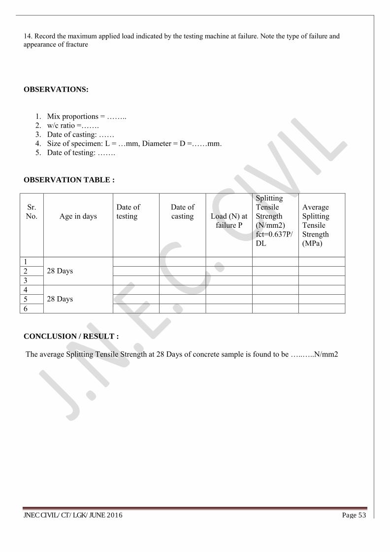
14. Record the maximum applied load indicated by the testing machine at failure. Note the type of failure and appearance of fracture
OBSERVATIONS:
1. Mix proportions = ……..2. w/c ratio =…….3. Date of casting: ……4. Size of specimen: L = …mm, Diameter = D =……mm.5. Date of testing: …….
OBSERVATION TABLE :
Sr. No. Age in days
Date of testing
Date of casting Load (N) at
failure P
Splitting Tensile Strength(N/mm2)fct=0.637P/DL
Average Splitting Tensile Strength(MPa)
128 Days 2
34
28 Days 56
CONCLUSION / RESULT :
The average Splitting Tensile Strength at 28 Days of concrete sample is found to be …..…..N/mm2

JNEC CIVIL/CT/LGK/JUNE 2016 Page 54