MAHATMA GANDHI MISSION’S JAWAHARLAL NEHRU …jnec.org/Lab-manuals/CIVIL/Fluid Mechanics I lab...
30
JNEC CIVIL/FM-I/LKK/Aug 2014 Page 1 MAHATMA GANDHI MISSION’S JAWAHARLAL NEHRU ENGINEERING COLLEGE, AURANGABAD. (M.S.) DEPARTMENT OF CIVIL ENGINEERING FLUID MECHANICS I LAB MANUAL Prepared By Approved By Prof. L. K. Kokate Dr. S. B. Shinde Lab Incharge H.O.D. Civil
Transcript of MAHATMA GANDHI MISSION’S JAWAHARLAL NEHRU …jnec.org/Lab-manuals/CIVIL/Fluid Mechanics I lab...
JNEC CIVIL/FM-I/LKK/Aug 2014 Page 1
MAHATMA GANDHI MISSION’SJAWAHARLAL NEHRU ENGINEERING COLLEGE,
AURANGABAD. (M.S.)
DEPARTMENT OF CIVIL ENGINEERING
FLUID MECHANICS I LAB MANUAL
Prepared By Approved ByProf. L. K. Kokate Dr. S. B. ShindeLab Incharge H.O.D. Civil
JNEC CIVIL/FM-I/LKK/Aug 2014 Page 2
Vision of Civil Department
The department of Civil Engineering strives to produce qualified engineers, researchers and professionals to serve the society with sustainable development.
Mission of Civil Department
∑ To provide quality education and prepare competitive graduates for successful career in Civil Engineering.
∑ To develop research opportunities that creates competent professionals who are trained in the design and development of environment friendly Civil Engineering system.
Program Educational Objectives
I. Graduates of Civil Engineering Program will be prepared to take the challenges in the field of Civil Engineering.
II. To provide Graduates with a sound Knowledge in mathematical, scientific and Civil Engineering fundamentals required to solve engineering problems and also to pursue higher studies.
III. To train students with good scientific and engineering breadth in Construction industry & many field of Civil Engineering.
IV. To build the confidence of students leading to professional and ethical integrity, effective communication skill, leadership, so that they can apply engineering knowledge for betterment of society.
V. To provide a good competitive learning environment so that graduates of Civil Engineering will be ready to meet the needs of Indian and multinational construction industries.
Program specific outcomes
The students are able to demonstrate:
1. The knowledge of planning and designing of the system components for building planning, transportation, water resources, estimating, costing and scheduling the construction processes.
2. The fundamental knowledge of analysis and design of various structures with an understanding of associated safety, quality and economy.
3. The knowledge of field data collection and material characterization to provide constructive and creative engineering solutions that reflect social and environmental sensitivities.
JNEC CIVIL/FM-I/LKK/Aug 2014 Page 3
‘FLUID MECHANICS -I’ EXPERIMENTS
CLASS: - Second Year Civil Engineering
LIST OF EXPERIMENTS
Sr. No. Name of Experiment Page No.
From To
I Study of pressure measuring devices.
II Determination of meta centric height. 3 5
III Calibration of Bernoulli’s equation. 6 8
IV Calibration of Venturimeter. 9 12
V Determination of Hydraulic coefficient for orifices. 13 16
VI Determination of coefficient of discharge for mouthpiece. 17 19
VII Calibration of Rectangular notch. 20 24
VIII Calibration of Triangular Notch. 25 29
IX Study of electrical analogy method for plotting of flow nets.
Time Allotted for each Practical Session = 02 Hrs.
JNEC CIVIL/FM-I/LKK/Aug 2014 Page 4
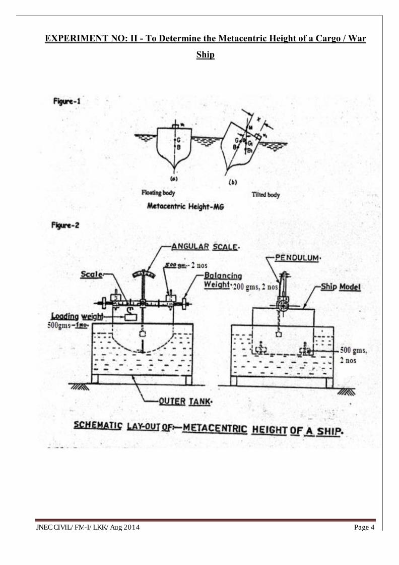
EXPERIMENT NO: II - To Determine the Metacentric Height of a Cargo / War
Ship
JNEC CIVIL/FM-I/LKK/Aug 2014 Page 5
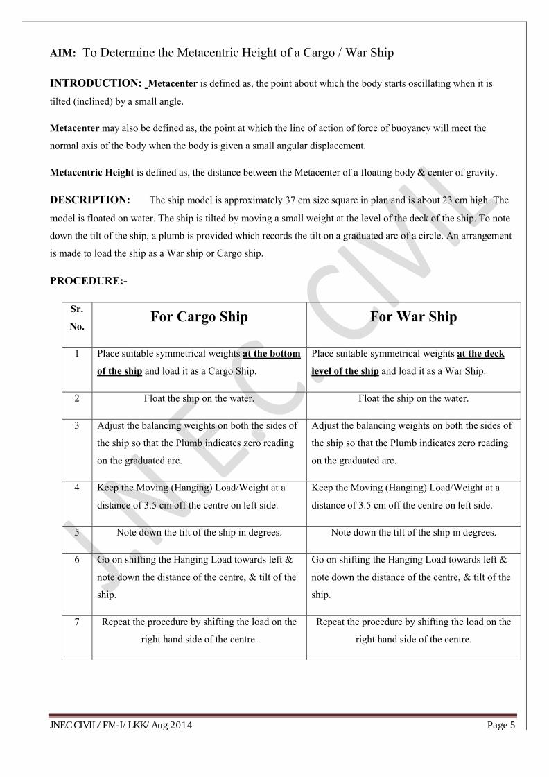
AIM: To Determine the Metacentric Height of a Cargo / War Ship
INTRODUCTION: Metacenter is defined as, the point about which the body starts oscillating when it is
tilted (inclined) by a small angle.
Metacenter may also be defined as, the point at which the line of action of force of buoyancy will meet the
normal axis of the body when the body is given a small angular displacement.
Metacentric Height is defined as, the distance between the Metacenter of a floating body & center of gravity.
DESCRIPTION: The ship model is approximately 37 cm size square in plan and is about 23 cm high. The
model is floated on water. The ship is tilted by moving a small weight at the level of the deck of the ship. To note
down the tilt of the ship, a plumb is provided which records the tilt on a graduated arc of a circle. An arrangement
is made to load the ship as a War ship or Cargo ship.
PROCEDURE:-
Sr.
No.For Cargo Ship For War Ship
1 Place suitable symmetrical weights at the bottom
of the ship and load it as a Cargo Ship.
Place suitable symmetrical weights at the deck
level of the ship and load it as a War Ship.
2 Float the ship on the water. Float the ship on the water.
3 Adjust the balancing weights on both the sides of
the ship so that the Plumb indicates zero reading
on the graduated arc.
Adjust the balancing weights on both the sides of
the ship so that the Plumb indicates zero reading
on the graduated arc.
4 Keep the Moving (Hanging) Load/Weight at a
distance of 3.5 cm off the centre on left side.
Keep the Moving (Hanging) Load/Weight at a
distance of 3.5 cm off the centre on left side.
5 Note down the tilt of the ship in degrees. Note down the tilt of the ship in degrees.
6 Go on shifting the Hanging Load towards left &
note down the distance of the centre, & tilt of the
ship.
Go on shifting the Hanging Load towards left &
note down the distance of the centre, & tilt of the
ship.
7 Repeat the procedure by shifting the load on the
right hand side of the centre.
Repeat the procedure by shifting the load on the
right hand side of the centre.
JNEC CIVIL/FM-I/LKK/Aug 2014 Page 6
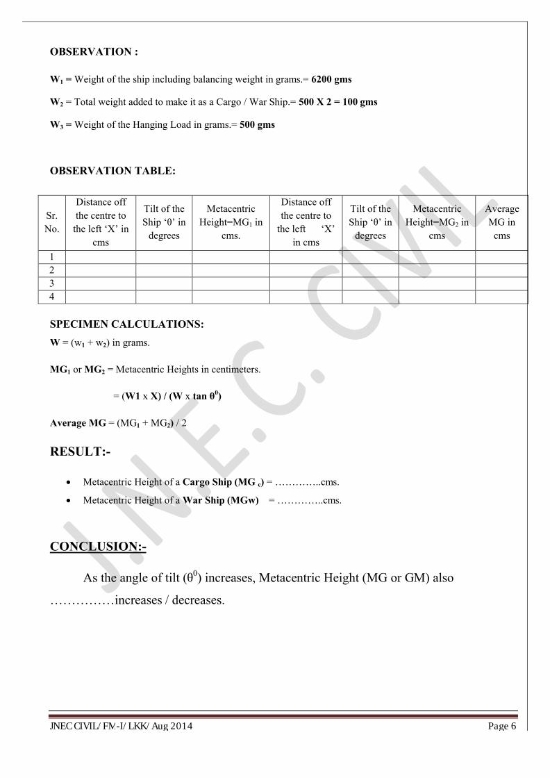
OBSERVATION :
W1 = Weight of the ship including balancing weight in grams.= 6200 gms
W2 = Total weight added to make it as a Cargo / War Ship.= 500 X 2 = 100 gms
W3 = Weight of the Hanging Load in grams.= 500 gms
OBSERVATION TABLE:
SPECIMEN CALCULATIONS:
W = (w1 + w2) in grams.
MG1 or MG2 = Metacentric Heights in centimeters.
= (W1 x X) / (W x tan θ0)
Average MG = (MG1 + MG2) / 2
RESULT:-
∑ Metacentric Height of a Cargo Ship (MG c) = …………..cms.
∑ Metacentric Height of a War Ship (MGw) = …………..cms.
CONCLUSION:-
As the angle of tilt (θ0) increases, Metacentric Height (MG or GM) also
……………increases / decreases.
Sr. No.
Distance off the centre to
the left ‘X’ in cms
Tilt of the Ship ‘θ’ in
degrees
Metacentric Height=MG1 in
cms.
Distance off the centre to
the left ‘X’ in cms
Tilt of the Ship ‘θ’ in
degrees
Metacentric Height=MG2 in
cms
Average MG in
cms
1234
JNEC CIVIL/FM-I/LKK/Aug 2014 Page 7
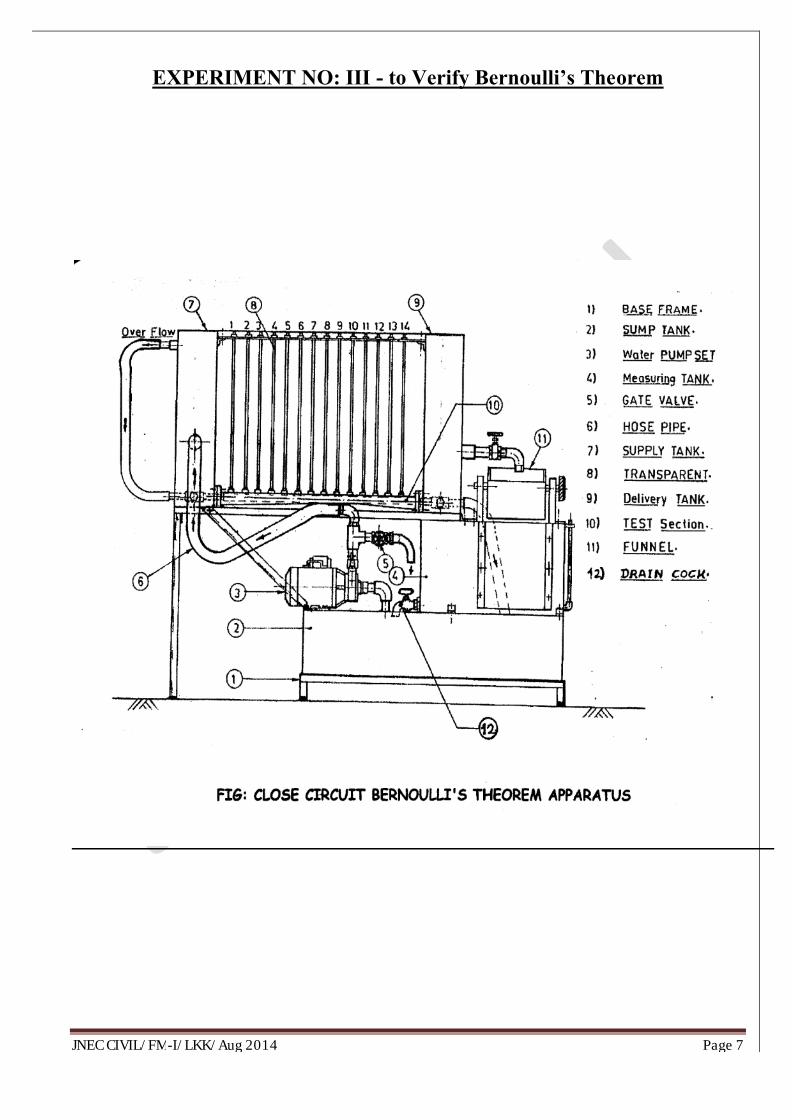
EXPERIMENT NO: III - to Verify Bernoulli’s Theorem
JNEC CIVIL/FM-I/LKK/Aug 2014 Page 8
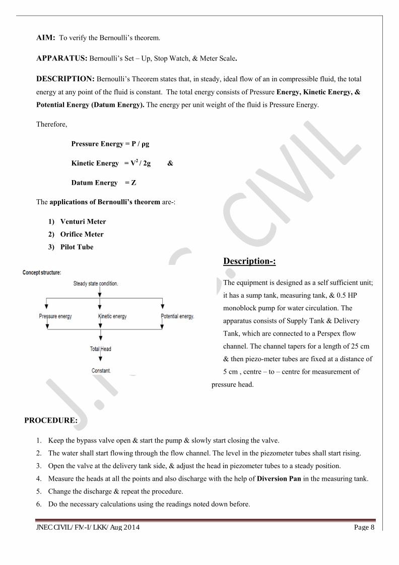
AIM: To verify the Bernoulli’s theorem.
APPARATUS: Bernoulli’s Set – Up, Stop Watch, & Meter Scale.
DESCRIPTION: Bernoulli’s Theorem states that, in steady, ideal flow of an in compressible fluid, the total
energy at any point of the fluid is constant. The total energy consists of Pressure Energy, Kinetic Energy, &
Potential Energy (Datum Energy). The energy per unit weight of the fluid is Pressure Energy.
Therefore,
Pressure Energy = P / ρg
Kinetic Energy = V2 / 2g &
Datum Energy = Z
The applications of Bernoulli’s theorem are-:
1) Venturi Meter
2) Orifice Meter
3) Pilot Tube
Description-:
The equipment is designed as a self sufficient unit;
it has a sump tank, measuring tank, & 0.5 HP
monoblock pump for water circulation. The
apparatus consists of Supply Tank & Delivery
Tank, which are connected to a Perspex flow
channel. The channel tapers for a length of 25 cm
& then piezo-meter tubes are fixed at a distance of
5 cm , centre – to – centre for measurement of
pressure head.
PROCEDURE:
1. Keep the bypass valve open & start the pump & slowly start closing the valve.
2. The water shall start flowing through the flow channel. The level in the piezometer tubes shall start rising.
3. Open the valve at the delivery tank side, & adjust the head in piezometer tubes to a steady position.
4. Measure the heads at all the points and also discharge with the help of Diversion Pan in the measuring tank.
5. Change the discharge & repeat the procedure.
6. Do the necessary calculations using the readings noted down before.
JNEC CIVIL/FM-I/LKK/Aug 2014 Page 9
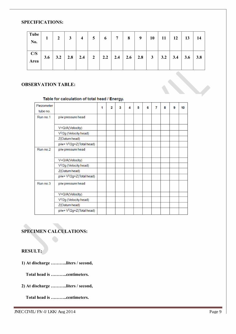
SPECIFICATIONS:
Tube
No.1 2 3 4 5 6 7 8 9 10 11 12 13 14
C/S
Area3.6 3.2 2.8 2.4 2 2.2 2.4 2.6 2.8 3 3.2 3.4 3.6 3.8
OBSERVATION TABLE:
SPECIMEN CALCULATIONS:
RESULT:
1) At discharge ………..liters / second,
Total head is ………..centimeters.
2) At discharge ………..liters / second,
Total head is ………..centimeters.
JNEC CIVIL/FM-I/LKK/Aug 2014 Page 10
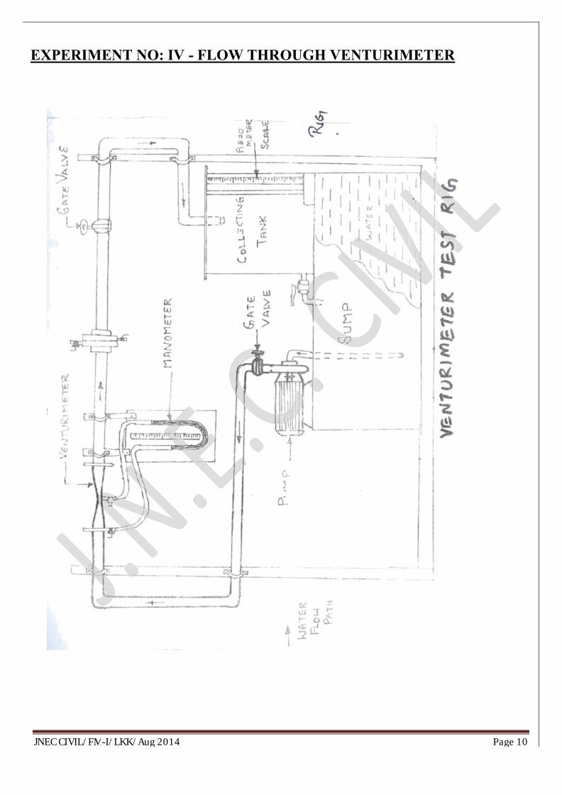
EXPERIMENT NO: IV - FLOW THROUGH VENTURIMETER
JNEC CIVIL/FM-I/LKK/Aug 2014 Page 11
AIM: To determine the co-efficient (K) of the Venturimeter.
DESCRIPTION:
Venturimeter is a device, used to measure the discharge of any liquid flowing through a pipe line. The
pressure difference between the inlet and the throat of the Venturimeter is recorded using a mercury differential
manometer, and the time is recorded for a measured discharge. Venturimeters are used to measure the flow rate of
fluid in a pipe. It consists of a short length of pipe tapering to a narrow throat in the middle and then diverging
gradually due to the reduced area and hence there is a pressure drop. By measuring the pressure drop with a
manometer, the flow rate can be calculated by applying Bernoulli’s equation.
The meters are fitted in the piping system with sufficiently long pipe lengths (greater than 10 mm diameter)
upstream of the meters. Each pipe has the respective Venturimeter with quick action cocks for pressure tappings.
These pressure tappings are connected to a common middle chamber, which in turn is connected to a differential
manometer. Each pipe line is provided with a flow control water is collected in an M.S. collecting tank of cross
sectional are 0.4 m x 0.4 m provided with gauge scale fitting and drain valve.
PROCEDURE:
1. The diameters of the inlet and throat are recorded and the internal plan
dimensions of the collecting tank are measured.
2. Keeping the outlet valve closed, the inlet valve is opened fully.
3. The outlet vale is opened slightly and the manometric heads in both the limbs (h1 and h2) are noted.
4. The outlet valve of the collecting tank is closed tightly and the time‘t’ required for ‘H’ rise of water
in the collecting tank is observed using a stop watch.
5. The above procedure is repeated by gradually increasing the flow and observing the required
readings.
6. The observations are tabulated and the co-efficient of the Venturimeter is computed.
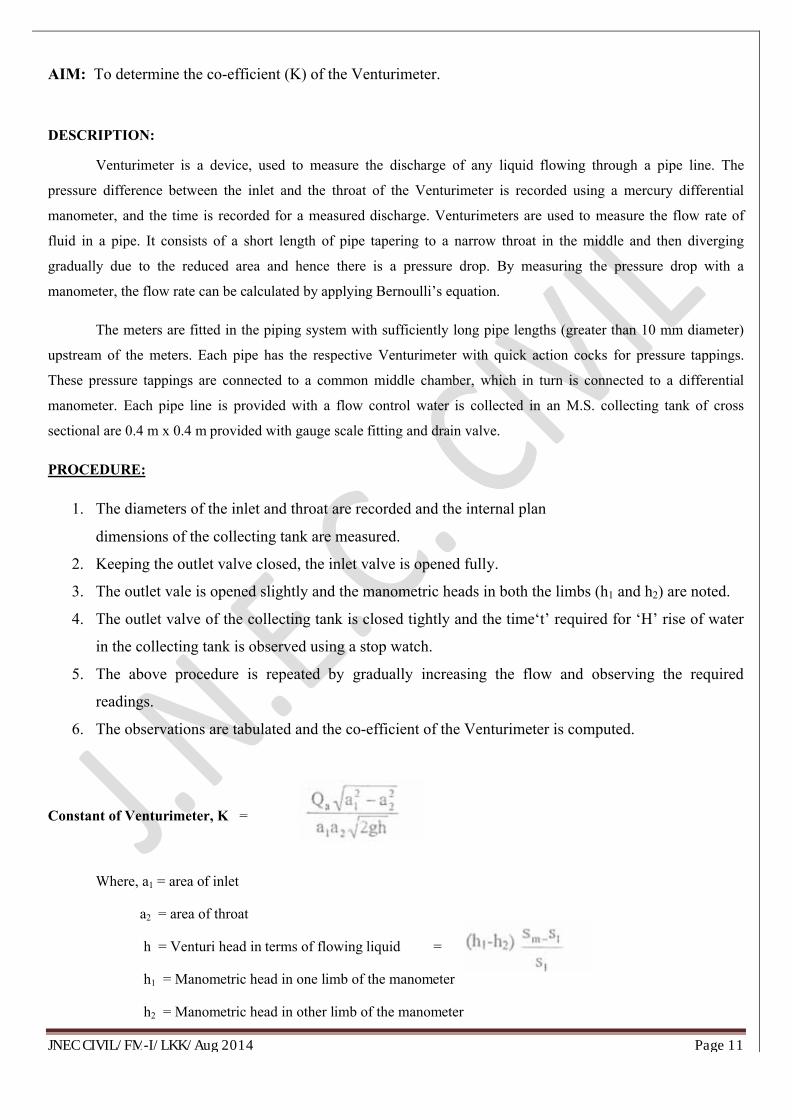
Constant of Venturimeter, K =
Where, a1 = area of inlet
a2 = area of throat
h = Venturi head in terms of flowing liquid =
h1 = Manometric head in one limb of the manometer
h2 = Manometric head in other limb of the manometer
JNEC CIVIL/FM-I/LKK/Aug 2014 Page 12
Sm = Specific gravity of following liquid
S1 = Specific gravity of following liquid
g = Acceleration due to gravity
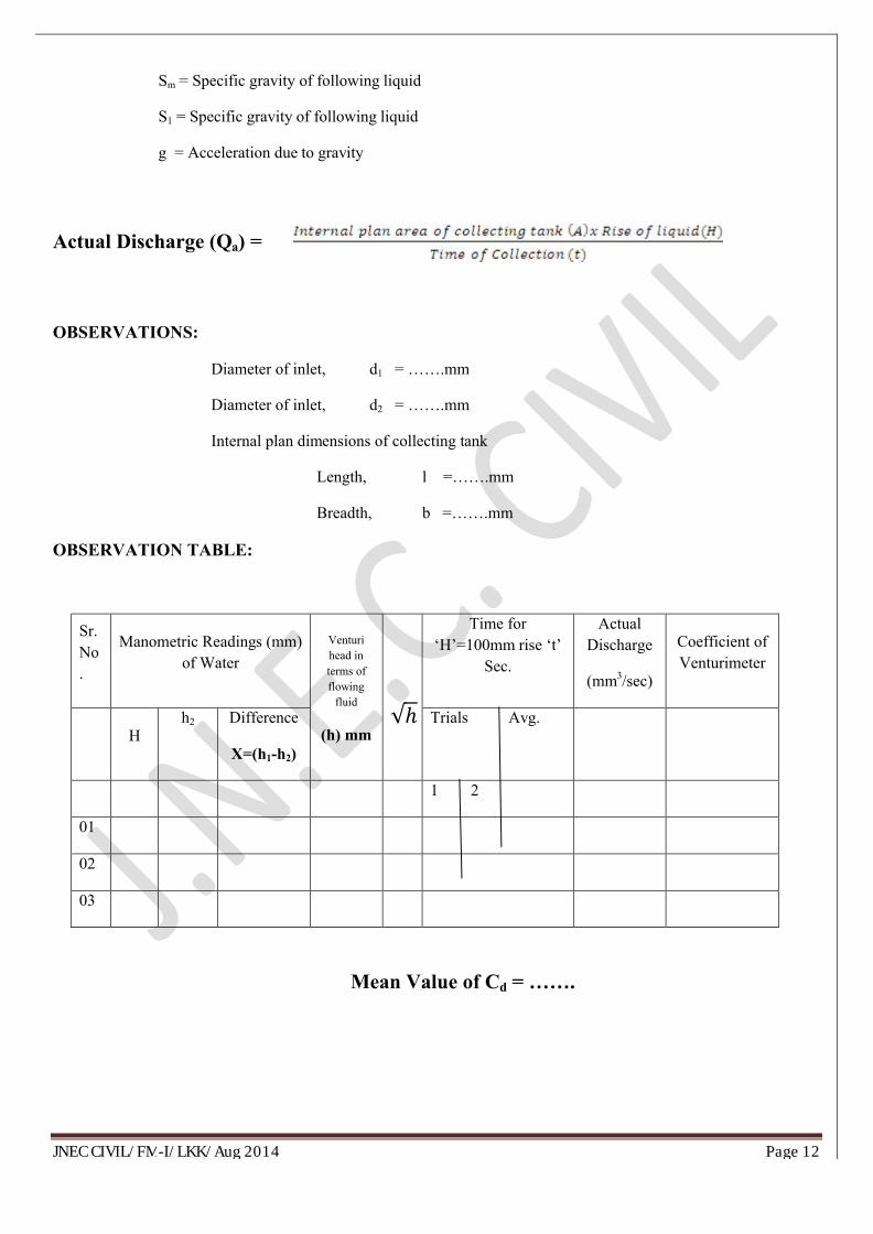
Actual Discharge (Qa) =
OBSERVATIONS:
Diameter of inlet, d1 = …….mm
Diameter of inlet, d2 = …….mm
Internal plan dimensions of collecting tank
Length, l =…….mm
Breadth, b =…….mm
OBSERVATION TABLE:
Sr. No.
Manometric Readings (mm) of Water
Venturi head in terms of flowing
fluid
(h) mm√ℎ
Time for ‘H’=100mm rise ‘t’
Sec.
Actual Discharge
(mm3/sec)
Coefficient of Venturimeter
Hh2 Difference
X=(h1-h2)
Trials Avg.
1 2
01
02
03
Mean Value of Cd = …….
JNEC CIVIL/FM-I/LKK/Aug 2014 Page 13
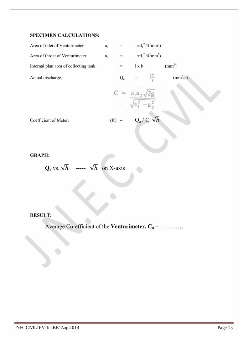
SPECIMEN CALCULATIONS:
Area of inlet of Venturimeter a1 = πd12 /4 (mm2)
Area of throat of Venturimeter a2 = πd22 /4 (mm2)
Internal plan area of collecting tank = l x b (mm2)
Actual discharge, Qa =??
? (mm3/s)
Coefficient of Meter, (K) = Qa / C. √ℎ
GRAPH:
Qa vs. √ℎ ----- √ℎ on X-axis
RESULT:
Average Co-efficient of the Venturimeter, Cd = …………
JNEC CIVIL/FM-I/LKK/Aug 2014 Page 14
EXPERIMENT NO: IV DETERMINATION OF HYDRAULIC COEFFICIENT FOR
ORIFICES
JNEC CIVIL/FM-I/LKK/Aug 2014 Page 15
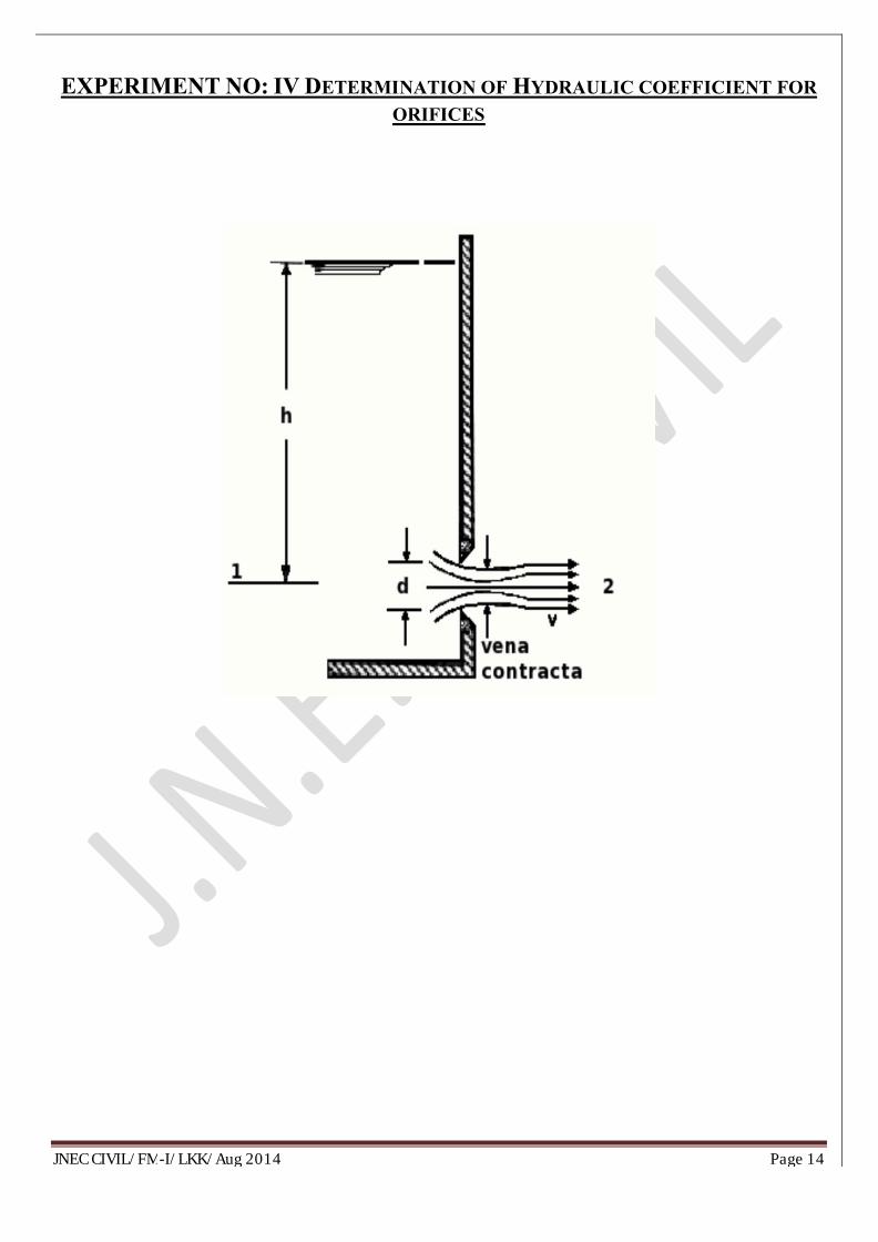
AIM: The objective of this experiment is to find and study the variations of hydraulic coefficients under different operating conditions of the given orifice.
APPARATUS: orifice apparatus , measuring tanks , a stopwatch & sliding hook gauge to measure the co-ordinates of the moving jet.
DISCRIPTION:∑ Orifice is a at sharp edged small circular hole fitted in one side of a reservoir containing fluid. It may
be classified on the basis of their size, shape, upstream edge and the discharge conditions. Most commonly used are circular and rectangular orifices. It is used to determine the discharge through a tank.
∑ The thickness of the wall is assumed to be small compared to the diameter of the orifice. Because of the convergence of the stream-lines approaching the orifice, the cross section of the jet decreases slightly until the pressure is equalized over the cross-section, and the velocity profile is nearlyrectangular. This point of minimum area is called the‘vena contracta’ .
∑ Beyond the vena contracta, friction with the Fluid outside the jet (air) slows it down, and the cross section increases. This divergence is usually quite small, and the jet is nearly cylindrical with aConstant velocity. The jet is held together by surface tension. The ratio of the area of vena contracta to the orifice area is called the coefficient of contraction.
The theoretical discharge through the orifice will be,
Qth = a0 x √(2 g h)
where, a0 = area of the orifice (cm2)h = Constant Head (cm)g = acceleration due to gravity, 981 (cm/ sec2)
The actual discharge is less than the theoretical discharge due to friction loss and the loss due to expansionof the jet. The actual discharge through the orifice can be determined using the collecting tank andstopwatch setup.
Qac = (A x R) / t
where, A = area of the collecting tank (cm2).R = height difference of the water column in the piezometer, (cm)t = time taken to rise R meters, (sec)
The coefficient of discharge CD is defined as the ratio of the actual discharge to theoretical discharge.
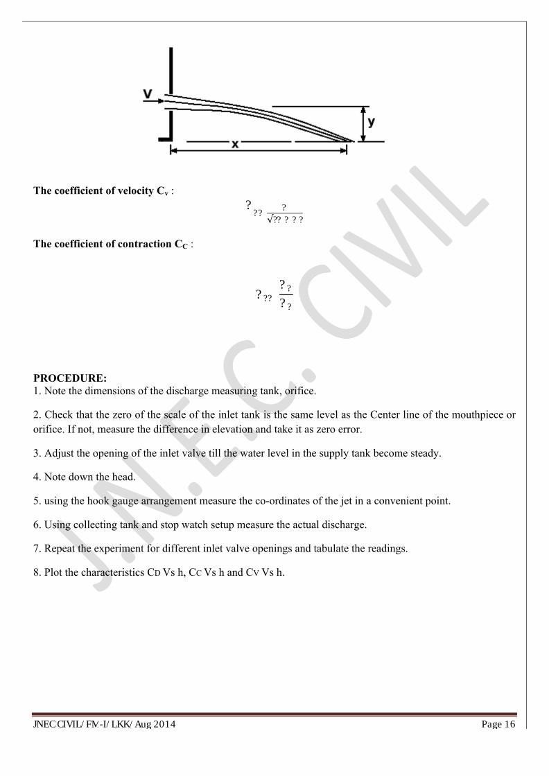
The actual velocity of the jet through the orifice is found out by measuring the co-ordinates of the moving jet and applying Newton’s laws. Refer figure below. The co-ordinates x and y of any point on the jet are measured using the sliding hook gauge.
JNEC CIVIL/FM-I/LKK/Aug 2014 Page 16
The coefficient of velocity Cv : ??? ?√?? ? ??The coefficient of contraction CC :
??? ????
PROCEDURE:1. Note the dimensions of the discharge measuring tank, orifice.
2. Check that the zero of the scale of the inlet tank is the same level as the Center line of the mouthpiece or orifice. If not, measure the difference in elevation and take it as zero error.
3. Adjust the opening of the inlet valve till the water level in the supply tank become steady.
4. Note down the head.
5. using the hook gauge arrangement measure the co-ordinates of the jet in a convenient point.
6. Using collecting tank and stop watch setup measure the actual discharge.
7. Repeat the experiment for different inlet valve openings and tabulate the readings.
8. Plot the characteristics CD Vs h, CC Vs h and CV Vs h.
JNEC CIVIL/FM-I/LKK/Aug 2014 Page 17
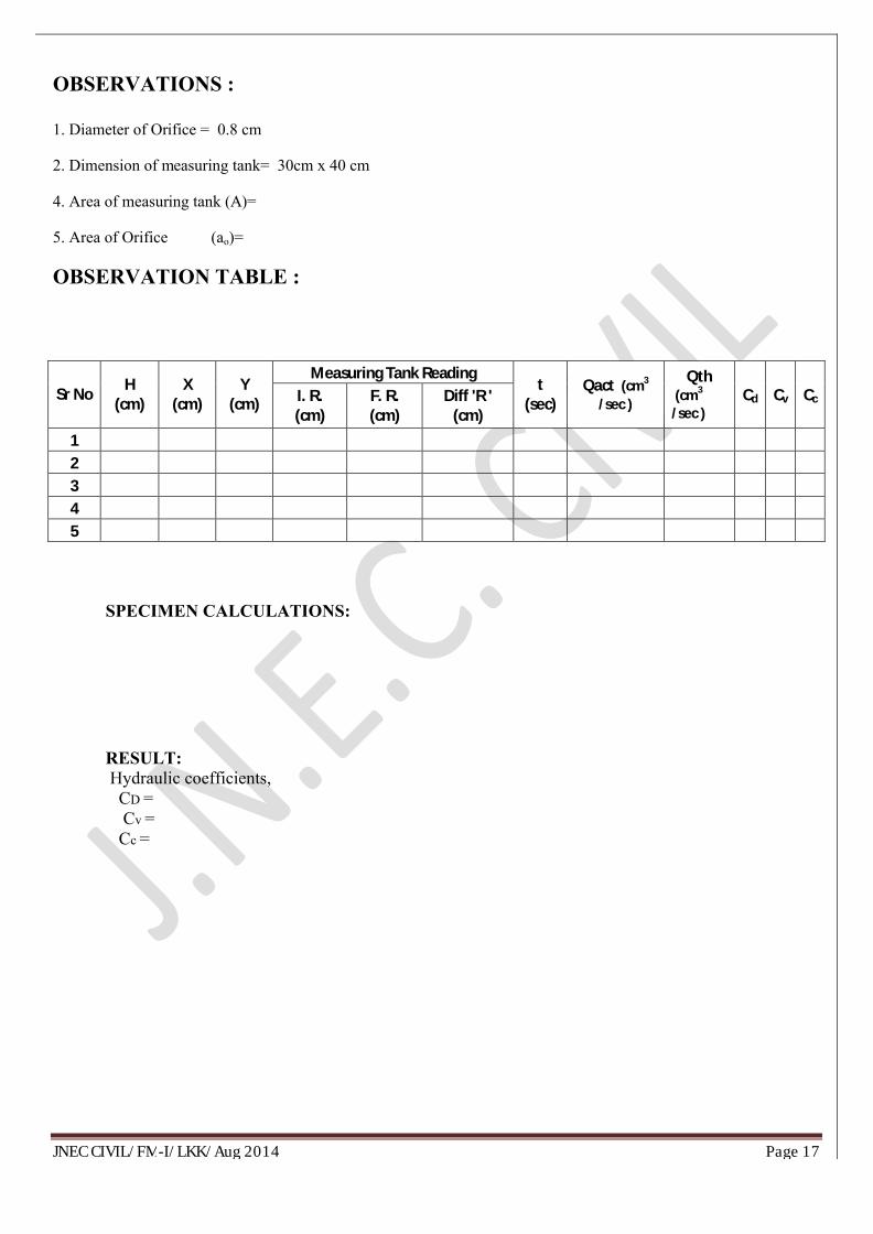
OBSERVATIONS :
1. Diameter of Orifice = 0.8 cm
2. Dimension of measuring tank= 30cm x 40 cm
4. Area of measuring tank (A)=
5. Area of Orifice (ao)=
OBSERVATION TABLE :
Sr No H (cm)
X (cm)
Y (cm)
Measuring Tank Readingt
(sec)Qact (cm3
/sec )
Qth(cm3
/sec )Cd Cv CcI. R.
(cm)F. R. (cm)
Diff 'R ' (cm)
12345
SPECIMEN CALCULATIONS:
RESULT:Hydraulic coefficients, CD =Cv =Cc =
JNEC CIVIL/FM-I/LKK/Aug 2014 Page 18
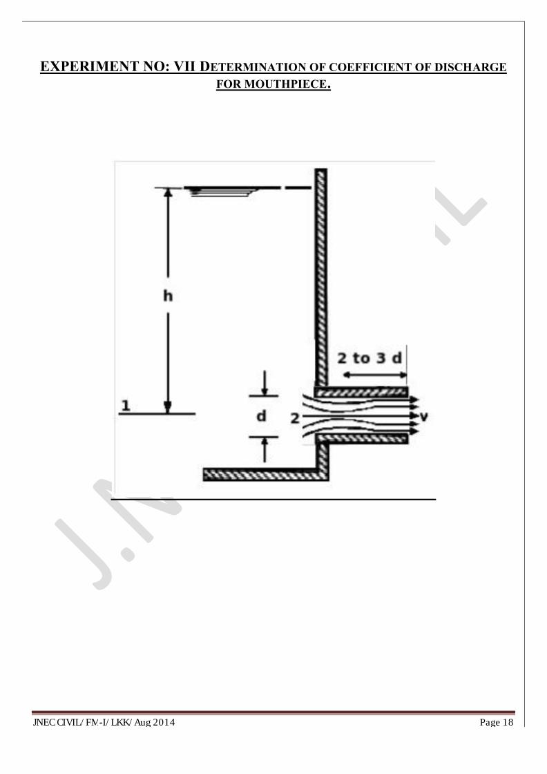
EXPERIMENT NO: VII DETERMINATION OF COEFFICIENT OF DISCHARGE
FOR MOUTHPIECE.
JNEC CIVIL/FM-I/LKK/Aug 2014 Page 19
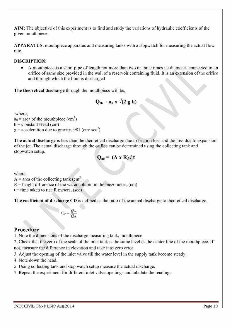
AIM: The objective of this experiment is to find and study the variations of hydraulic coefficients of the given mouthpiece.
APPARATUS: mouthpiece apparatus and measuring tanks with a stopwatch for measuring the actual flow rate.
DISCRIPTION:
∑ A mouthpiece is a short pipe of length not more than two or three times its diameter, connected to an orifice of same size provided in the wall of a reservoir containing fluid. It is an extension of the orifice and through which the fluid is discharged
The theoretical discharge through the mouthpiece will be,
Qth = a0 x √(2 g h)
where, a0 = area of the mouthpiece (cm2)h = Constant Head (cm)g = acceleration due to gravity, 981 (cm/ sec2)
The actual discharge is less than the theoretical discharge due to friction loss and the loss due to expansion of the jet. The actual discharge through the orifice can be determined using the collecting tank andstopwatch setup.
Qac = (A x R) / t
where, A = area of the collecting tank (cm2).R = height difference of the water column in the piezometer, (cm)t = time taken to rise R meters, (sec)
The coefficient of discharge CD is defined as the ratio of the actual discharge to theoretical discharge.
Procedure1. Note the dimensions of the discharge measuring tank, mouthpiece.2. Check that the zero of the scale of the inlet tank is the same level as the center line of the mouthpiece. If not, measure the difference in elevation and take it as zero error.3. Adjust the opening of the inlet valve till the water level in the supply tank become steady.4. Note down the head.5. Using collecting tank and stop watch setup measure the actual discharge.7. Repeat the experiment for different inlet valve openings and tabulate the readings.
JNEC CIVIL/FM-I/LKK/Aug 2014 Page 20
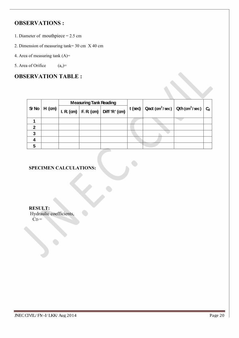
OBSERVATIONS :
1. Diameter of mouthpiece = 2.5 cm
2. Dimension of measuring tank= 30 cm X 40 cm
4. Area of measuring tank (A)=
5. Area of Orifice (ao)=
OBSERVATION TABLE :
Sr No H (cm)Measuring Tank Reading
t (sec) Qact (cm3 /sec ) Qth (cm3 /sec ) CdI. R. (cm) F. R. (cm) Diff 'R ' (cm)
12345
SPECIMEN CALCULATIONS:
RESULT:Hydraulic coefficients, CD =
JNEC CIVIL/FM-I/LKK/Aug 2014 Page 21
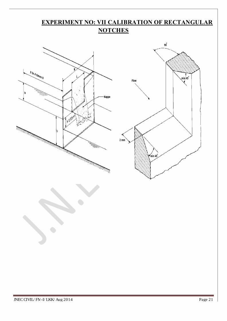
EXPERIMENT NO: VII CALIBRATION OF RECTANGULARNOTCHES
JNEC CIVIL/FM-I/LKK/Aug 2014 Page 22
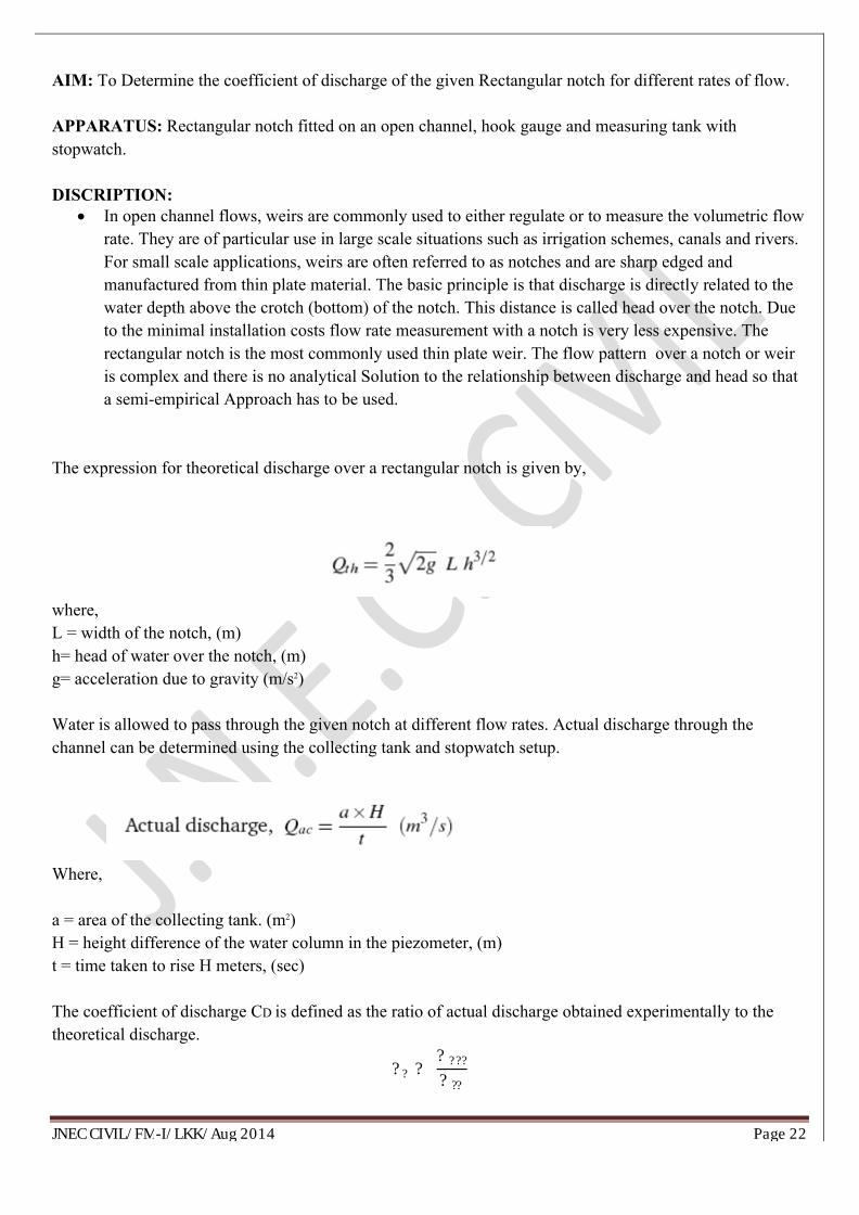
AIM: To Determine the coefficient of discharge of the given Rectangular notch for different rates of flow.
APPARATUS: Rectangular notch fitted on an open channel, hook gauge and measuring tank with stopwatch.
DISCRIPTION: ∑ In open channel flows, weirs are commonly used to either regulate or to measure the volumetric flow
rate. They are of particular use in large scale situations such as irrigation schemes, canals and rivers. For small scale applications, weirs are often referred to as notches and are sharp edged andmanufactured from thin plate material. The basic principle is that discharge is directly related to thewater depth above the crotch (bottom) of the notch. This distance is called head over the notch. Due to the minimal installation costs flow rate measurement with a notch is very less expensive. The rectangular notch is the most commonly used thin plate weir. The flow pattern over a notch or weir is complex and there is no analytical Solution to the relationship between discharge and head so that a semi-empirical Approach has to be used.
The expression for theoretical discharge over a rectangular notch is given by,
where,L = width of the notch, (m)h= head of water over the notch, (m)g= acceleration due to gravity (m/s2)
Water is allowed to pass through the given notch at different flow rates. Actual discharge through the channel can be determined using the collecting tank and stopwatch setup.
Where,
a = area of the collecting tank. (m2)H = height difference of the water column in the piezometer, (m)t = time taken to rise H meters, (sec)
The coefficient of discharge CD is defined as the ratio of actual discharge obtained experimentally to the theoretical discharge.
?? ? ???????
JNEC CIVIL/FM-I/LKK/Aug 2014 Page 23
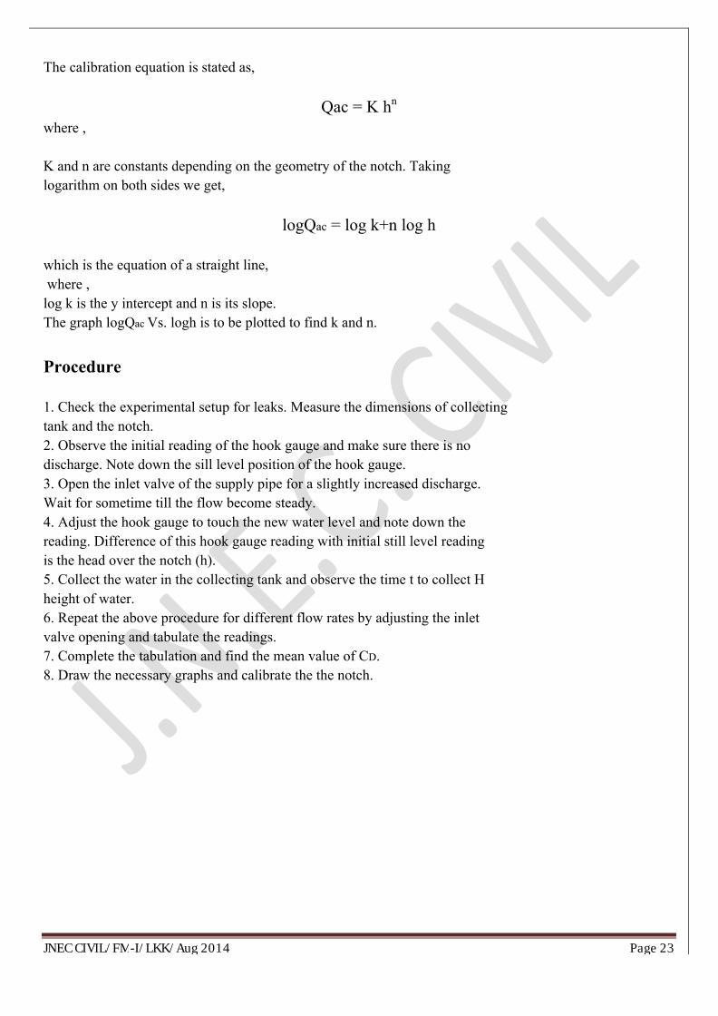
The calibration equation is stated as,
Qac = K hn
where ,
K and n are constants depending on the geometry of the notch. Takinglogarithm on both sides we get,
logQac = log k+n log h
which is the equation of a straight line,where ,log k is the y intercept and n is its slope. The graph logQac Vs. logh is to be plotted to find k and n.
Procedure
1. Check the experimental setup for leaks. Measure the dimensions of collectingtank and the notch.2. Observe the initial reading of the hook gauge and make sure there is nodischarge. Note down the sill level position of the hook gauge.3. Open the inlet valve of the supply pipe for a slightly increased discharge.Wait for sometime till the flow become steady.4. Adjust the hook gauge to touch the new water level and note down thereading. Difference of this hook gauge reading with initial still level readingis the head over the notch (h).5. Collect the water in the collecting tank and observe the time t to collect Hheight of water.6. Repeat the above procedure for different flow rates by adjusting the inletvalve opening and tabulate the readings.7. Complete the tabulation and find the mean value of CD.8. Draw the necessary graphs and calibrate the the notch.
JNEC CIVIL/FM-I/LKK/Aug 2014 Page 24
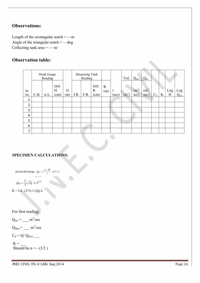
Observations:
Length of the rectangular notch = —mAngle of the triangular notch = —degCollecting tank area = — m2
Observation table:
Sr. No.
Hook Guage Reading
H (m)
Measuring Tank Reading
t (sec)
Vol. Qact Qth
Cd KLog H
Log QactC.B. w.L.
Diff.H (cm) I.R. F.R.
Diff.R (cm)
R. (m)
(m3)(m3/ sec)
(m3/ sec)
1234567
SPECIMEN CALCULATIONS:
K = Cd .(2/3).√ (2g) L
For first reading:
Qact = ___ m3/sec
Qtheo = ___ m3/sec
Cd = Q/ Qtheo ___
K = ___Should be n =~ (3/2 )
JNEC CIVIL/FM-I/LKK/Aug 2014 Page 25
If we take the log for the two sides of equation :
log Q = log K + n log H ,
where n : the power of H = ___ ( the slope.) from table .
log k = ___ from graph → k = ___ → Cd = ___ .
Results :
The average coefficient of discharge of the given for Triangular notch, Cd =Cd From Graph=
.
______________________________________________________________________________________
JNEC CIVIL/FM-I/LKK/Aug 2014 Page 26
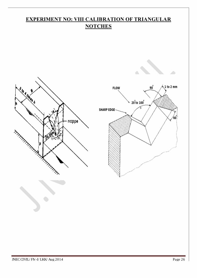
EXPERIMENT NO: VIII CALIBRATION OF TRIANGULARNOTCHES
JNEC CIVIL/FM-I/LKK/Aug 2014 Page 27
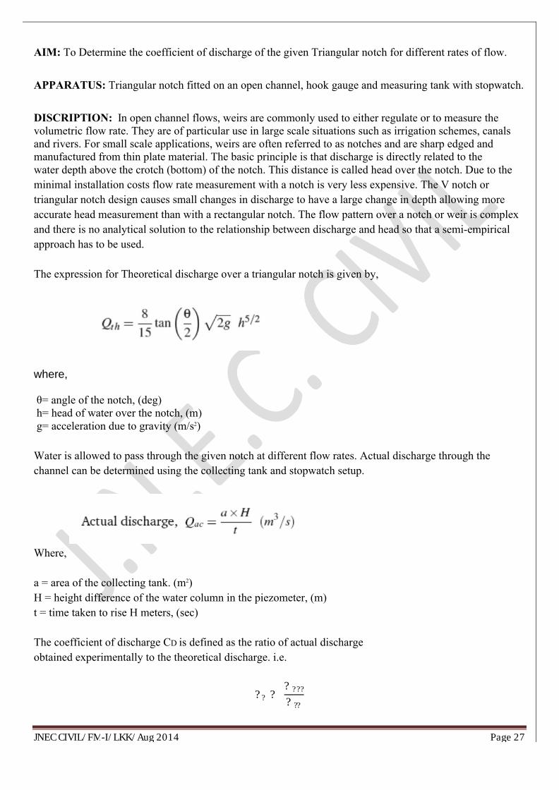
AIM: To Determine the coefficient of discharge of the given Triangular notch for different rates of flow.
APPARATUS: Triangular notch fitted on an open channel, hook gauge and measuring tank with stopwatch.
DISCRIPTION: In open channel flows, weirs are commonly used to either regulate or to measure the volumetric flow rate. They are of particular use in large scale situations such as irrigation schemes, canals and rivers. For small scale applications, weirs are often referred to as notches and are sharp edged and manufactured from thin plate material. The basic principle is that discharge is directly related to thewater depth above the crotch (bottom) of the notch. This distance is called head over the notch. Due to the minimal installation costs flow rate measurement with a notch is very less expensive. The V notch or triangular notch design causes small changes in discharge to have a large change in depth allowing more accurate head measurement than with a rectangular notch. The flow pattern over a notch or weir is complex and there is no analytical solution to the relationship between discharge and head so that a semi-empiricalapproach has to be used.
The expression for Theoretical discharge over a triangular notch is given by,
where,
θ= angle of the notch, (deg)h= head of water over the notch, (m)g= acceleration due to gravity (m/s2)
Water is allowed to pass through the given notch at different flow rates. Actual discharge through the channel can be determined using the collecting tank and stopwatch setup.
Where,
a = area of the collecting tank. (m2)H = height difference of the water column in the piezometer, (m)t = time taken to rise H meters, (sec)
The coefficient of discharge CD is defined as the ratio of actual dischargeobtained experimentally to the theoretical discharge. i.e.
?? ? ???????
JNEC CIVIL/FM-I/LKK/Aug 2014 Page 28
The calibration equation is stated as,
Qac = K hn
where ,
K and n are constants depending on the geometry of the notch. Takinglogarithm on both sides we get,
logQac = log k+n log h
which is the equation of a straight line,where ,log k is the y intercept and n is its slope. The graph logQac Vs. logh is to be plotted to find k and n.
Procedure1. Check the experimental setup for leaks. Measure the dimensions of collectingtank and the notch.2. Observe the initial reading of the hook gauge and make sure there is nodischarge. Note down the sill level position of the hook gauge.3. Open the inlet valve of the supply pipe for a slightly increased discharge.Wait for sometime till the flow become steady.4. Adjust the hook gauge to touch the new water level and note down thereading. Difference of this hook gauge reading with initial still level readingis the head over the notch (h).5. Collect the water in the collecting tank and observe the time t to collect Hheight of water.6. Repeat the above procedure for different flow rates by adjusting the inletvalve opening and tabulate the readings.7. Complete the tabulation and find the mean value of CD.8. Draw the necessary graphs and calibrate the the notch.
JNEC CIVIL/FM-I/LKK/Aug 2014 Page 29
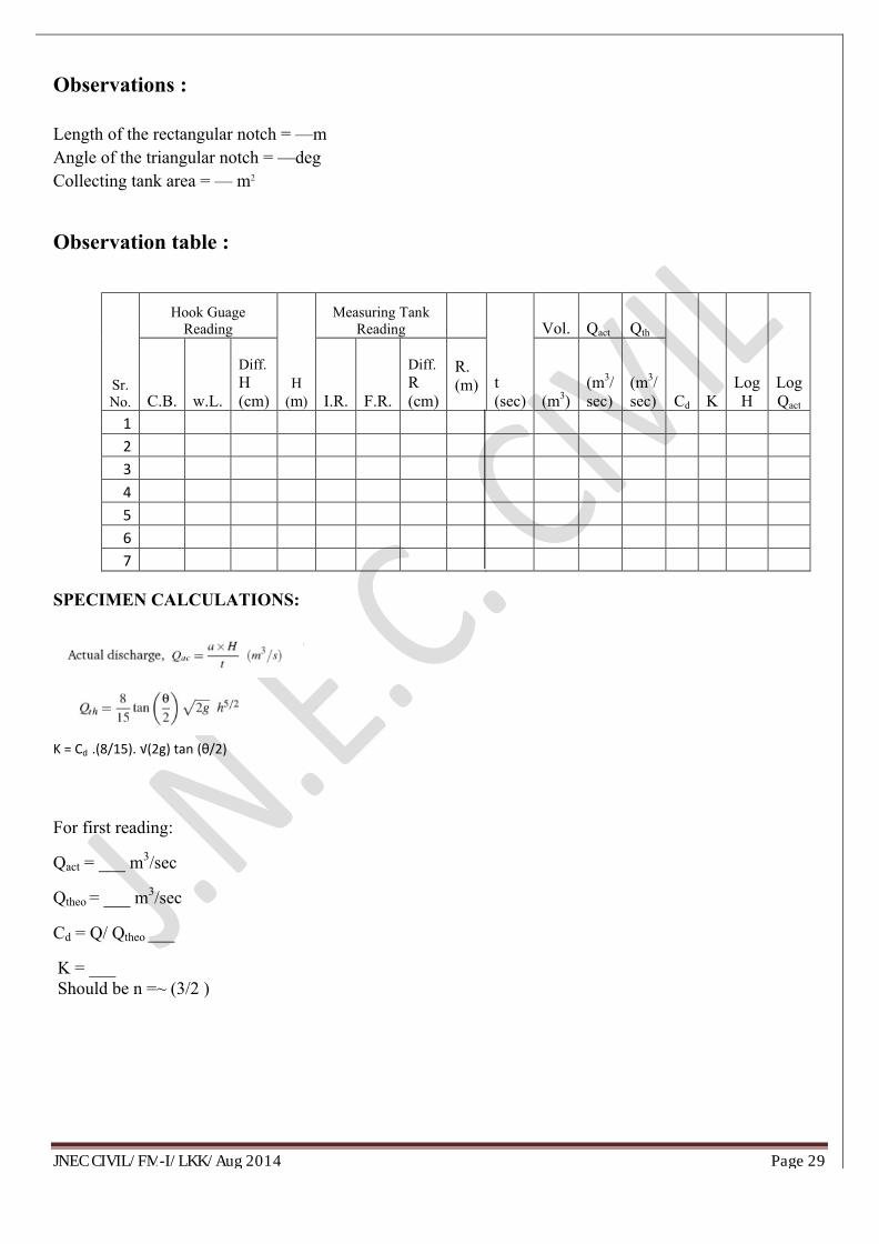
Observations :
Length of the rectangular notch = —mAngle of the triangular notch = —degCollecting tank area = — m2
Observation table :
Sr. No.
Hook Guage Reading
H (m)
Measuring Tank Reading
t (sec)
Vol. Qact Qth
Cd KLog H
Log QactC.B. w.L.
Diff.H (cm) I.R. F.R.
Diff.R (cm)
R. (m)
(m3)(m3/ sec)
(m3/ sec)
1234567
SPECIMEN CALCULATIONS:
K = Cd .(8/15). √(2g) tan (θ/2)
For first reading:
Qact = ___ m3/sec
Qtheo = ___ m3/sec
Cd = Q/ Qtheo ___
K = ___Should be n =~ (3/2 )
JNEC CIVIL/FM-I/LKK/Aug 2014 Page 30
If we take the log for the two sides of equation :
log Q = log K + n log H ,
where n : the power of H = ___ ( the slope.) from table .
log k = ___ from graph → k = ___ → Cd = ___ .
Results :
The average coefficient of discharge of the given for Triangular notch, Cd =Cd From Graph=
_____________________________________________________________________________________