
Maharishi Arvind
14
Maharishi Arvind Institute of Engineering & Technology Sector-7 Madhyam Marg Mansarovar Jaipur LAB MANUAL LAB CODE: 6CE4-21 LAB NAME : Environmental Engineering Design and Lab SEMESTER : VI BRANCH: Civil Engineering Prepared by Dinesh Verma
Transcript of Maharishi Arvind
Maharishi Arvind Institute of Engineering & Technology
Sector-7 Madhyam Marg Mansarovar Jaipur
LAB MANUALLAB CODE: 6CE4-21
LAB NAME : Environmental EngineeringDesign and Lab
SEMESTER : VI
BRANCH: Civil Engineering
Prepared byDinesh Verma
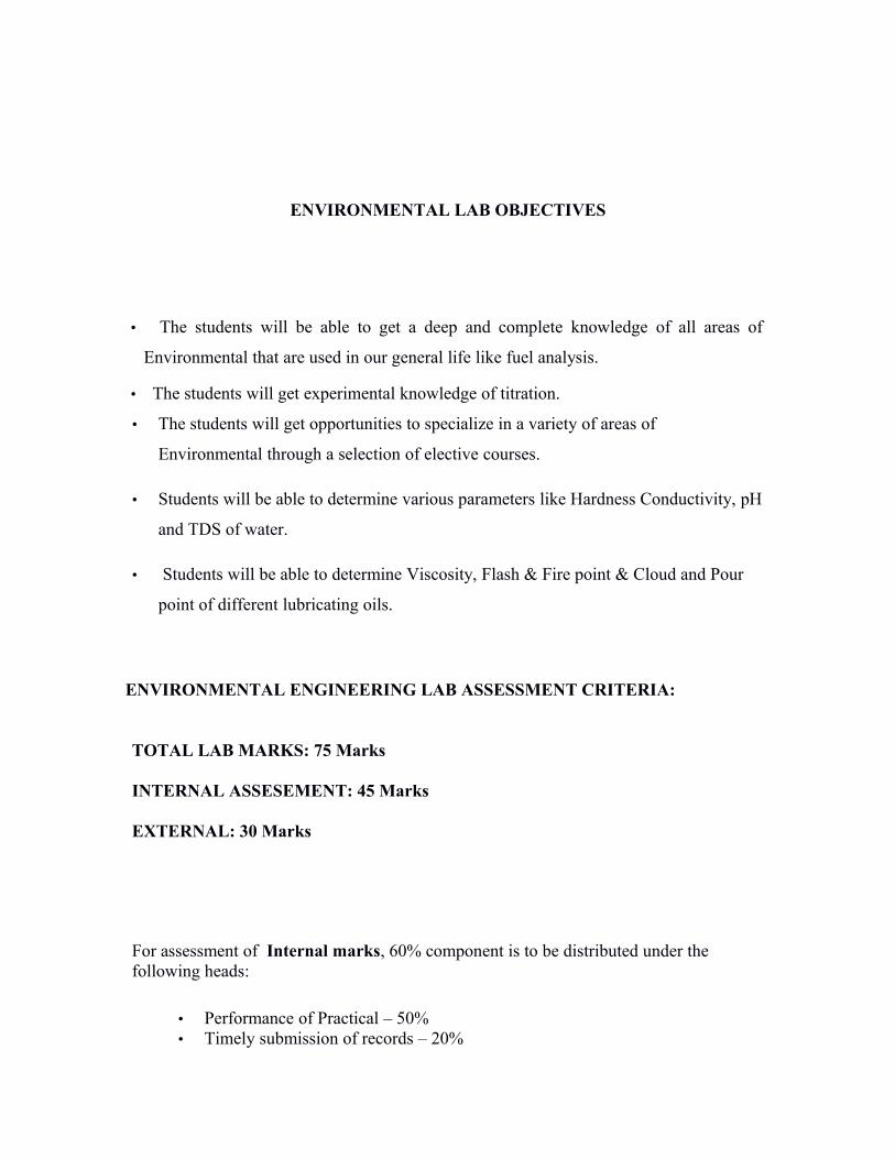
ENVIRONMENTAL LAB OBJECTIVES
• The students will be able to get a deep and complete knowledge of all areas of
Environmental that are used in our general life like fuel analysis.
• The students will get experimental knowledge of titration.
• The students will get opportunities to specialize in a variety of areas of
Environmental through a selection of elective courses.
• Students will be able to determine various parameters like Hardness Conductivity, pH
and TDS of water.
• Students will be able to determine Viscosity, Flash & Fire point & Cloud and Pour
point of different lubricating oils.
ENVIRONMENTAL ENGINEERING LAB ASSESSMENT CRITERIA:
TOTAL LAB MARKS: 75 Marks
INTERNAL ASSESEMENT: 45 Marks
EXTERNAL: 30 Marks
For assessment of Internal marks, 60% component is to be distributed under the following heads:
• Performance of Practical – 50%• Timely submission of records – 20%
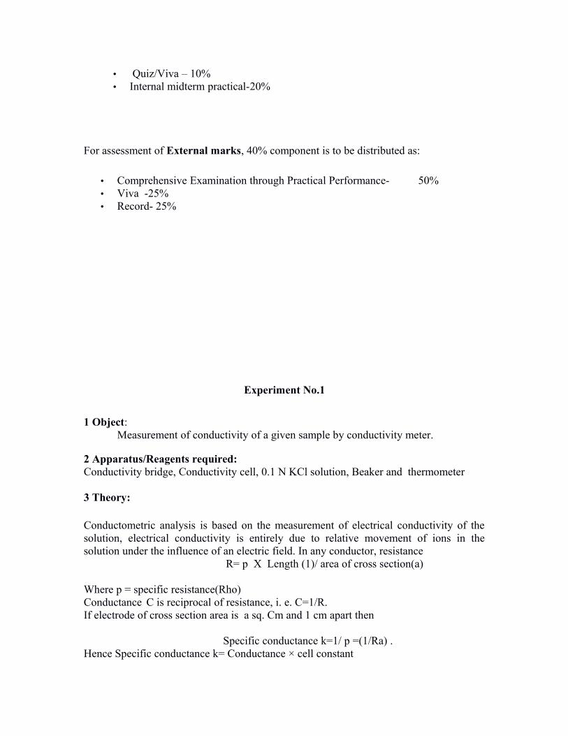
• Quiz/Viva – 10%• Internal midterm practical-20%
For assessment of External marks, 40% component is to be distributed as:
• Comprehensive Examination through Practical Performance- 50%• Viva -25% • Record- 25%
Experiment No.1
1 Object: Measurement of conductivity of a given sample by conductivity meter.
2 Apparatus/Reagents required: Conductivity bridge, Conductivity cell, 0.1 N KCl solution, Beaker and thermometer
3 Theory:
Conductometric analysis is based on the measurement of electrical conductivity of thesolution, electrical conductivity is entirely due to relative movement of ions in thesolution under the influence of an electric field. In any conductor, resistance R= p Х Length (1)/ area of cross section(a)
Where p = specific resistance(Rho)Conductance C is reciprocal of resistance, i. e. C=1/R. If electrode of cross section area is a sq. Cm and 1 cm apart then
Specific conductance k=1/ p =(1/Ra) . Hence Specific conductance k= Conductance × cell constant
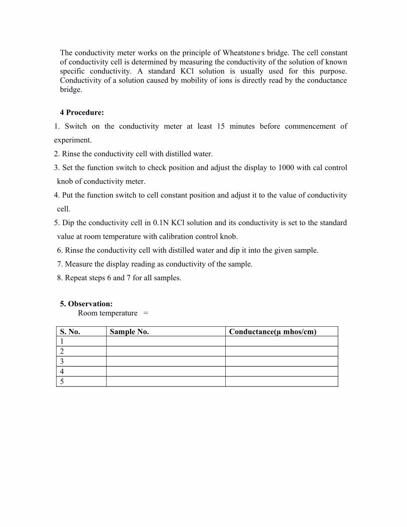
The conductivity meter works on the principle of Wheatstone ,s bridge. The cell constantof conductivity cell is determined by measuring the conductivity of the solution of knownspecific conductivity. A standard KCl solution is usually used for this purpose.Conductivity of a solution caused by mobility of ions is directly read by the conductancebridge.
4 Procedure:
1. Switch on the conductivity meter at least 15 minutes before commencement of
experiment.
2. Rinse the conductivity cell with distilled water.
3. Set the function switch to check position and adjust the display to 1000 with cal control
knob of conductivity meter.
4. Put the function switch to cell constant position and adjust it to the value of conductivity
cell.
5. Dip the conductivity cell in 0.1N KCl solution and its conductivity is set to the standard
value at room temperature with calibration control knob.
6. Rinse the conductivity cell with distilled water and dip it into the given sample.
7. Measure the display reading as conductivity of the sample.
8. Repeat steps 6 and 7 for all samples.
5. Observation: Room temperature =
S. No. Sample No. Conductance(µ mhos/cm)12345
6. Results:
The electrical conductivities of the given samples are------------
7. Precautions:
1) Temperature of the sample should be carefully noted as conductivity changes withtemperature.2) Conductivity cell should be properly dipped in the solution.3) At the end conductivity cell should be properly washed and dipped into distilled water
PO a b c d e f g h i j k l mmapping √ √ √
VIVA QUESTIONS Q.1 Define conductance.
Q.2 What is specific conductance?
Q.3 What is the unit of conductance?
Q.4 Name the factors affecting conductance.
Q.5 Which electrode is used for determination of conductance?
Q.6 What is the conductivity range of potable water?
Q.7 What is cell constant ?
Q.8 What is the effect of temperature on cell constant?
Experiment No. 2
OBJECT : To determine the pH of various water sample and classify the samples.
Apparatus/Reagents required:
pH meter, combined pH glass electrode, standard buffer solutions of pH 4, 7 and 9.2,100 ml beaker, water samples.
Theory: The basic principle of pH measurement is determination of activity of hydrogenions using a combined glass electrode. The glass electrode works on the fact that when athin glass membranes are in contact with solutions of different H+ ion concentration on itstwo sides, a potential difference is developed across and magnitude of difference dependsupon the difference in the H+ ion concentration.
The cell can be represented as Pt, O.IN HCl, glass / experimental solution/KCl(Salt, 50lm) Hg2Cl2, Hg The EmF of the cell at 250c is
E cell = E cal – EG= Ecal – (EG- 0.0591 pH)= 0.2420 – EG + 0.0591 pH
OrPh = Ecell- 0.2420 + EG/0.0591
On the basis of pH value, water will be classified as –
• Acidic pH<7.0• Basic (Alkaline) pH>7.0• Neutral pH =7.0
Procedure:
• Calibration of combined pH glass electrode:
•Connect the pH electrode to the socket of the pH meter, switch on the pH meter forabout 15 minutes keeping the function switch in the stand by position.
•Wash the bulb of pH electrode with soft tissue paper.•Adjust the temperature scale of pH meter according to the temp.of the sample
Solution.•Change function switch to pH mode.•Dip the electrode in the standard buffer solution of pH 7.•Adjust the calibrate control knob to display reading 7.0.•Repeat steps 5 and 6 with standard buffer solution of pH 4.0 and 9.2
• pH Measurement:
• Properly wash and dry the pH electrode and then dip it into the water samplesolution 1.
• Wait for one minute for steady reading.• Observe the reading & note down in the observation table.• Repeat the procedure for all the water samples given. • After completion of the experiment, wash the electrodes properly and dip it into
distilled water.
Observations:
S. No. Sample No. pH12
345
Results: On the basis of their pH Values, the above solutions are classified as Acidic : Sample No………………………….Alkaline : Sample No………………………….Neutral : Sample No………………………….
Precautions:
• The pH electrodes must be properly washed and dried before its use.• Always keep the function of pH meter on standby position after taking
readings.• Electrode should be properly dipped in the solution.• Never learn the electrode undipped in distilled water after completion of
the experiment.
VIVA QUESTIONS Q.1 What is the full form of pH?Q.2 What is the possible pH of pure water ?Q.3 What is a reference electrode ? Q.4 How pH meter is calibrated?Q.5 What is the significance of the experiment ?
Experiment No. 3
Object : To determine the turbidity of given sample water.
Chemicals: Dissolve 10.0gm hexamethylene tetra-ammine in distilled water and dilute to
100 ml.
Dissolve 1.0 gm hydrazine sulphate in distilled water and dilute to 100
ml.
Equipments: Nephlometer, Sample holder.
Principle : The term turbidity is applied to suspended matter present in water that
interferes with the passage of light through the water or in which visual depth is restricted
turbidity is caused by a wide variety of suspended materials that range in size from
colloidal to coarse to dispersions ,much of this material is inorganic in nature and
includes clay , slit and organic matter.
The turbidity is the expression of optical property that cause slight to be scattered and
absorbed rather than transmitted in straight lines through the samples. The standard
method for the determination of turbidity has been based on the Jackson Candle Turbidity
Meter. For lower turbidities as of treated water can be measured by nephlometer which is
based on the laws of Tyndale Effect.The amount of scattered light is proportional to the
turbidity of the solution under test.
The original standard chosen was 1mg SiO2/L = 1 unit of turbidity
The turbidity is reported in NTU
Procedure :
1. Insert three pin plugs into appropriate 230 V AC mains sockets.
2. Switch the instrument ON and allow 10-15 minutes warm up.
3. Select the appropriate range.
4. Set the CALIB control to maximum, clockwise position.
5. Insert the test tube with distilled water into a cell holder and cover with the light shield.
6. Adjust SET ZERO controls to get ZERO on the display.
7. Remove the test tube and replace with the test tube containing standard turbidity
solution.
8. Adjust CALIB CONTROL such that display indicates as follows:
Range Std. Solution Display0-1 NTU 1NTU 1.000-10 NTU 10NTU 10.00-100 NTU 100NTU 100.00-1000 NTU 500NTU 500
9. The instrument is now ready for test samples. Insert test tube containing unknown sample in cell holder. The display directly gives the turbidity in NTU.10. Rest tubes should be inserted in the holder with its markings aligned with the marking on the holder top.
Observations:
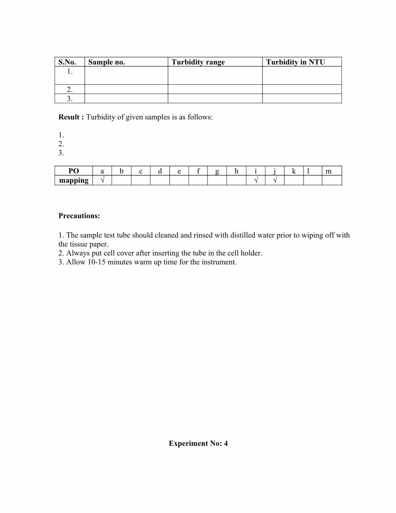
S.No. Sample no. Turbidity range Turbidity in NTU1.
2.3.
Result : Turbidity of given samples is as follows:
1.2.3.
PO a b c d e f g h i j k l mmapping √ √ √
Precautions:
1. The sample test tube should cleaned and rinsed with distilled water prior to wiping off with the tissue paper.2. Always put cell cover after inserting the tube in the cell holder.3. Allow 10-15 minutes warm up time for the instrument.
Experiment No: 4
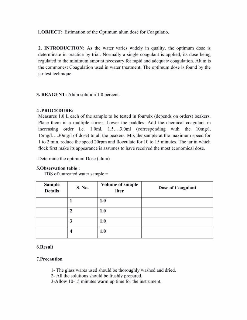
1.OBJECT: Estimation of the Optimum alum dose for Coagulatio.
2. INTRODUCTION: As the water varies widely in quality, the optimum dose isdeterminate in practice by trial. Normally a single coagulant is applied, its dose beingregulated to the minimum amount necessary for rapid and adequate coagulation. Alum isthe commonest Coagulation used in water treatment. The optimum dose is found by thejar test technique.
3. REAGENT: Alum solution 1.0 percent.
4 .PROCEDURE:Measures 1.0 L each of the sample to be tested in four/six (depends on orders) beakers.Place them in a multiple stirrer. Lower the paddles. Add the chemical coagulant inincreasing order i.e. 1.0ml, 1.5….3.0ml (corresponding with the 10mg/l,15mg/l….30mg/l of dose) to all the beakers. Mix the sample at the maximum speed for1 to 2 min. reduce the speed 20rpm and flocculate for 10 to 15 minutes. The jar in whichflock first make its appearance is assumes to have received the most economical dose.
Determine the optimum Dose (alum)
5.Observation table : TDS of untreated water sample =
SampleDetails
S. No.Volume of smaple
literDose of Coagulant
1 1.0
2 1.0
3 1.0
4 1.0
6.Result
7.Precaution
1- The glass wares used should be thoroughly washed and dried.2- All the solutions should be frashly prepared. 3-Allow 10-15 minutes warm up time for the instrument.


![g*tm /mR sU] - Hindu · PDF filemaharishi university of management. g*tm /mr su] maharishi university of management. maharishi university of management. maharishi university of management](https://static.fdocuments.in/doc/165x107/5aa91fbf7f8b9a81188c6353/gtm-mr-su-hindu-maharishi-university-of-management-gtm-mr-su-maharishi.jpg)


