Magnus Marklund , Rikard Gebart , David Fletcher Introduction
8
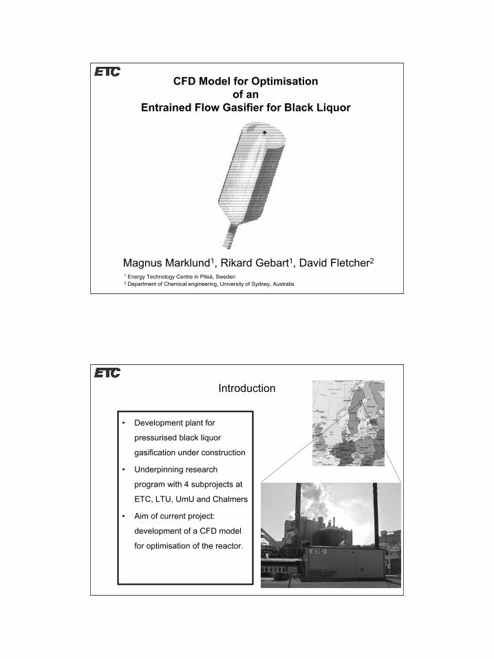
CFD Model for Optimisation of an Entrained Flow Gasifier for Black Liquor Magnus Marklund 1 , Rikard Gebart 1 , David Fletcher 2 1 Energy Technology Centre in Piteå, Sweden 2 Department of Chemical engineering, University of Sydney, Australia Introduction • Development plant for pressurised black liquor gasification under construction • Underpinning research program with 4 subprojects at ETC, LTU, UmU and Chalmers • Aim of current project: development of a CFD model for optimisation of the reactor.
Transcript of Magnus Marklund , Rikard Gebart , David Fletcher Introduction
1
CFD Model for Optimisationof an
Entrained Flow Gasifier for Black Liquor
Magnus Marklund1, Rikard Gebart1, David Fletcher2
1 Energy Technology Centre in Piteå, Sweden2 Department of Chemical engineering, University of Sydney, Australia
Introduction
• Development plant for
pressurised black liquor
gasification under construction
• Underpinning research
program with 4 subprojects at
ETC, LTU, UmU and Chalmers
• Aim of current project:
development of a CFD model
for optimisation of the reactor.
2
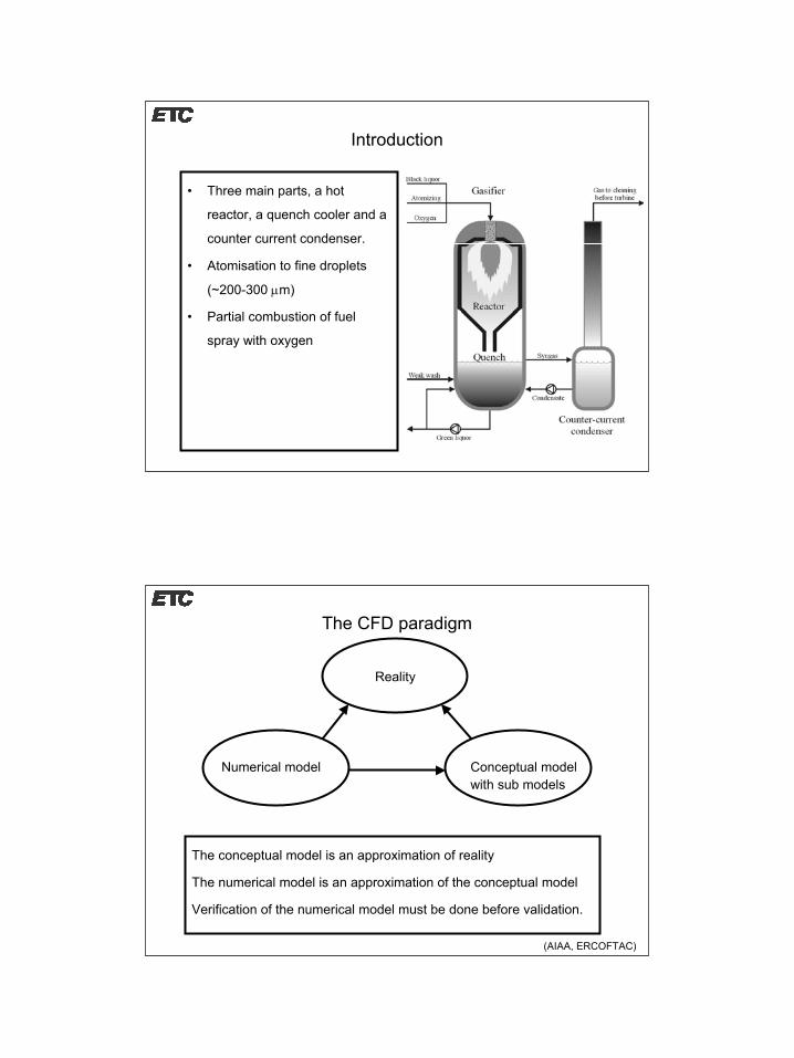
Introduction
• Three main parts, a hot
reactor, a quench cooler and a
counter current condenser.
• Atomisation to fine droplets
(~200-300 µm)
• Partial combustion of fuel
spray with oxygen
The CFD paradigm
The conceptual model is an approximation of reality
The numerical model is an approximation of the conceptual model
Verification of the numerical model must be done before validation.
Reality
Numerical model Conceptual modelwith sub models
(AIAA, ERCOFTAC)
3
Current model
• Based on CFX4 CFD code
• Distribution of non interacting discrete droplets forming a spray
• Droplet conversion by customised subroutines in the solver
• k-ε and Reynolds stress turbulence models
• Gas combustion modelled by Eddy Break Up/Kinetic model
• Discrete transfer model for thermal radiation
• Coupled solver for heat conduction in the walls
Model status
• Included gas species: O2, H2O, CO, H2, CO2, CH4
• Sulphur and sodium reactions neglected
• Combustion is controlled by mixing and kinetics
• Gas phase combustion reactions:
222
22
222
2224
2224
5.0 5.0
2 242
HCOOHCOCOOCOOHOH
OHCOOCHHCOOHCH
+⇔+⇒+⇒+
+⇒++⇒+
Temporarily neglected

4
Model verification
• Unexpectedly high flame temperature predicted by the model.
• Input parameters, model, numerical or programming errors?
• Simplified model of a long rectangular duct to verify the results.
• Mass flux of O2 (λ=1.1) and droplets at inlet
• Droplets consist only of CO (volatile matter) and smelt
• Constant specific heat
• Endothermic reactions from pyrolysis neglected
• Resulting outlet temperature can be computed by hand
Model verification
• Reactions run to completion well before the outlet from the plug
flow reactor
• CFD simulation predicts an outlet temperature of 2163 K.
• Hand calculation yields 2171 K.
• Overall error less than 1% likely to come from numerical errors
5
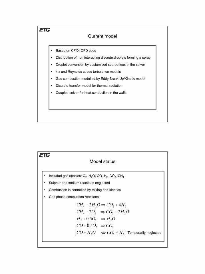
Uncertainty from input data
Pyrolysis rate
0102030405060708090
100
300 500 700 900 1100 1300 1500
T (K)
Rate
(1/s
)
Case ICase II
Pyrolysis rate parameters (λ (O2) = 0.4 in test case) :
• Case I: Standard values used for coal (Ubhayakar et. al.)
• Case II: 90 % of the activation energies in Case I
(Case II results in a faster pyrolysis compared to Case I, see graph)
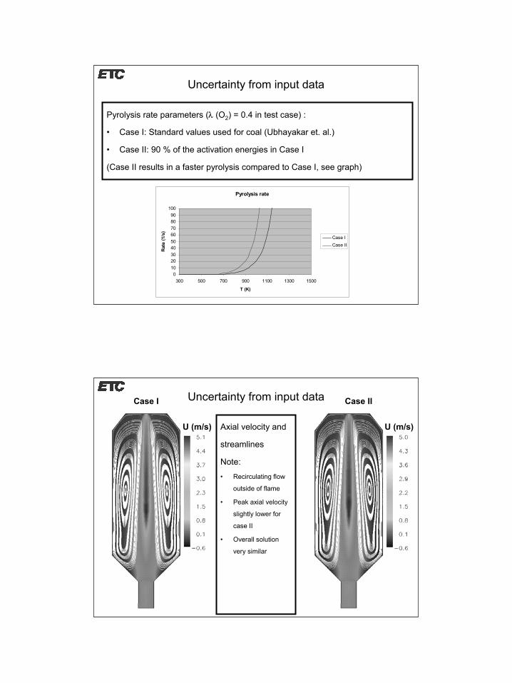
Uncertainty from input dataCase I Case II
Axial velocity and
streamlines
Note:• Recirculating flow
outside of flame
• Peak axial velocity
slightly lower for
case II
• Overall solution
very similar
U (m/s)U (m/s)
6
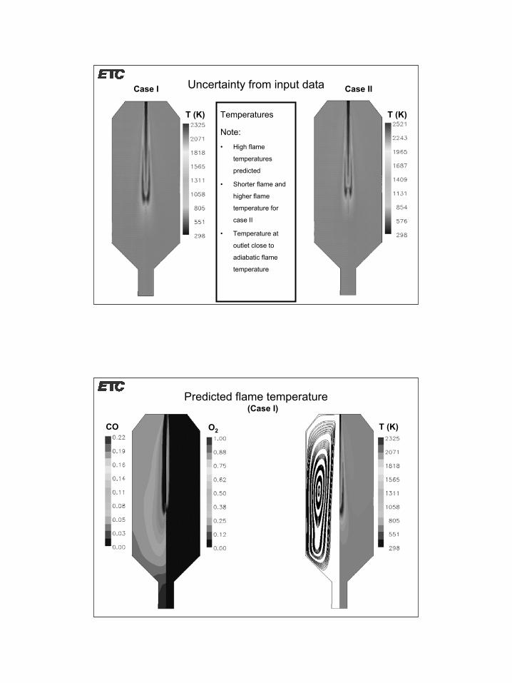
Uncertainty from input dataCase I Case II
Temperatures
Note:• High flame
temperatures
predicted
• Shorter flame and
higher flame
temperature for
case II
• Temperature at
outlet close to
adiabatic flame
temperature
T (K)T (K)
Predicted flame temperature(Case I)
CO O2 T (K)
7
Predicted flame temperature
• Recirculation brings hot reactive gases (e.g. CO) in contact with oxygen in the flame region
• The preheating of the fuel gas explains the high temperatures
• Conclusion: Flame temperature reasonable after all
• Addition of the water/gas shift reaction will lower the flame temperature
• Additional reactions (e.g. CO2 dissociation) may have to be included in the model if local temperatures becomes too high
Summary
• Partial verification of gasifier model for a plug flow reactor with an error less than 1%
• Relatively low sensitivity in the model from different devolatilization rates• Higher flame temperature and shorter flame length was detected for the
faster devolatilization rate• Locally high flame temperatures can be explained with recirculation of hot,
partially burnt fuel gas that gets in contact with oxygen• Water/gas shift reaction creates numerical instabilities but needs to be
included for accurate predictions of the gas composition and temperature
8
Future work
• Continue work on verification and sensitivity to input parameters• Perform optimisation studies on flame shapes in the DP1 reactor• Construct a pressurised test rig for qualitative (high speed photography
and flow visualisation) and quantitative (PDA) measurements of atomisation
• Candidate nozzles for the Chemrec reactor will be tested in the rig • Refine conjugate heat transfer model for prediction of temperature in
refractory lining and pressure vessel• Add sodium sulphate reduction chemistry to CFD model
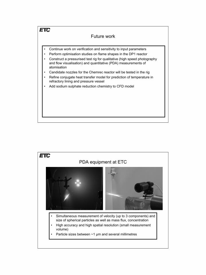
PDA equipment at ETC
• Simultaneous measurement of velocity (up to 3 components) and size of spherical particles as well as mass flux, concentration
• High accuracy and high spatial resolution (small measurement volume)
• Particle sizes between ~1 µm and several millimetres