Magnetics for Higher DC Imbalance - IEEE 802 · Magnetics for Higher DC Imbalance Brian Buckmeier...
26
1 Magnetics for Higher DC Imbalance Brian Buckmeier Bel Stewart Connector IEEE P802.3at DTE Power Enhancements Task Force Denver, CO March 6 - 10, 2006
Transcript of Magnetics for Higher DC Imbalance - IEEE 802 · Magnetics for Higher DC Imbalance Brian Buckmeier...
1
Magnetics forHigher DC Imbalance
Brian BuckmeierBel Stewart Connector
IEEE P802.3atDTE Power Enhancements Task Force
Denver, COMarch 6 - 10, 2006

IEEE P802.3at DTE Power Enhancements Task Force 2
Topics• 10/100/1000Base-T backward
compatible• Targeted 24mA and 34mA DC imbalance• Electrical parameters measured:• Insertion loss, Return Loss, OCL with DC
bias• Component power dissipation and
temperature rise• Distortion of Insertion Loss and Return
Loss with power applied• Component size increase, single port
and multi-port components

IEEE P802.3at DTE Power Enhancements Task Force 3
Schematic and Electrical Parameters• 1000Base-T circuit used for backward compatibility• Two pairs used for calculations, worst case scenario• Tested with 700mA of current
IEEE P802.3at DTE Power Enhancements Task Force 4
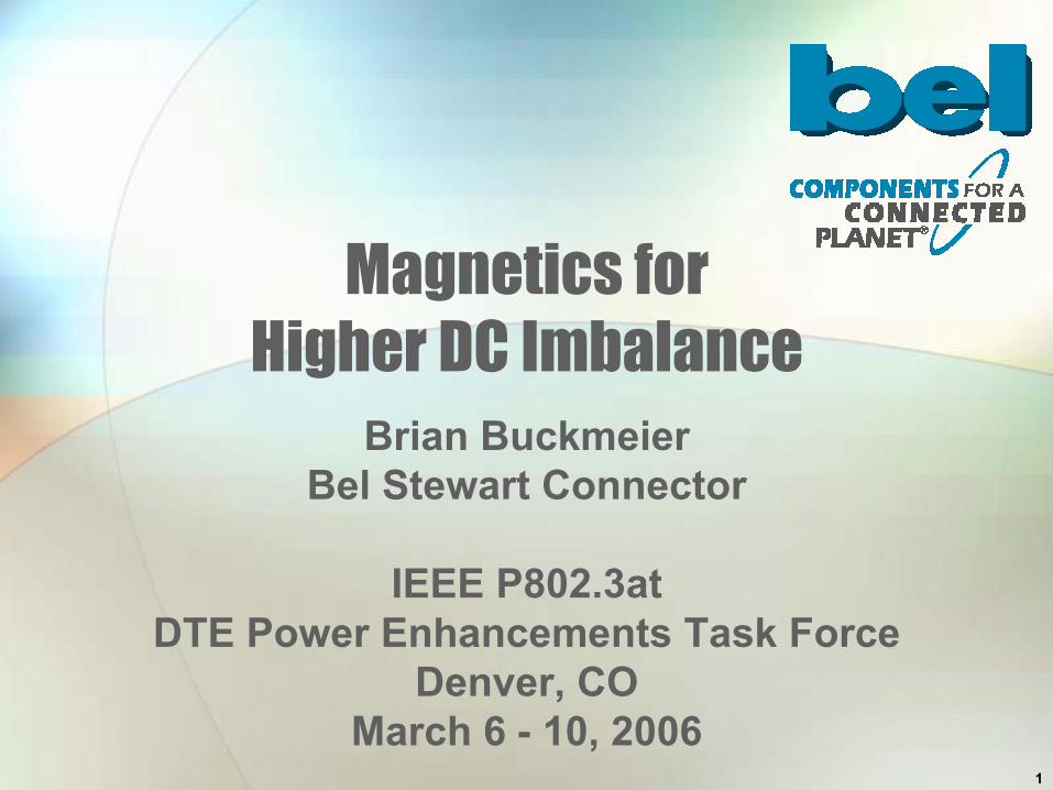
Insertion Loss• Insertion Loss without 700mA of current
applied to center tap of transformer
IEEE P802.3at DTE Power Enhancements Task Force 5
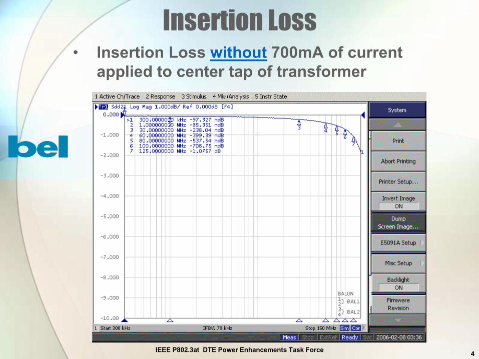
Insertion Loss• Insertion Loss without 700mA• Plot shows IL Test Fixture distortion

IEEE P802.3at DTE Power Enhancements Task Force 6
Insertion Loss• Insertion Loss with 700mA
IEEE P802.3at DTE Power Enhancements Task Force 7
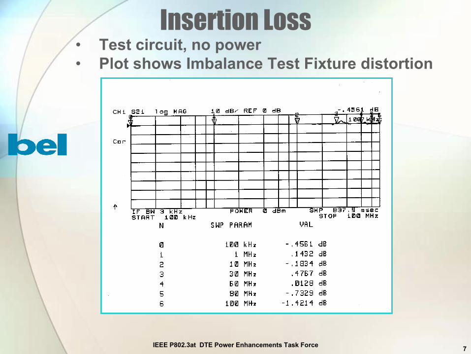
Insertion Loss• Test circuit, no power• Plot shows Imbalance Test Fixture distortion
IEEE P802.3at DTE Power Enhancements Task Force 8
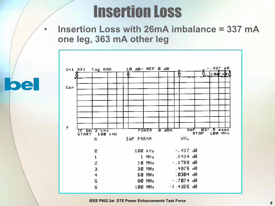
Insertion Loss• Insertion Loss with 26mA imbalance = 337 mA
one leg, 363 mA other leg

IEEE P802.3at DTE Power Enhancements Task Force 9
Insertion Loss - Conclusions
• Insertion Loss does not distort with 700mA• Insertion Loss does not degrade using
magnetics for 24 mA imbalance design
IEEE P802.3at DTE Power Enhancements Task Force 10
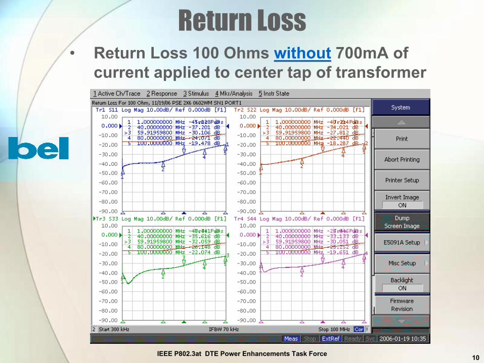
Return Loss• Return Loss 100 Ohms without 700mA of
current applied to center tap of transformer

IEEE P802.3at DTE Power Enhancements Task Force 11
Return Loss• Return Loss 115 Ohms without 700mA of
current applied to center tap of transformer

IEEE P802.3at DTE Power Enhancements Task Force 12
Return Loss• Return Loss 85 Ohms without 700mA of
current applied to center tap of transformer

IEEE P802.3at DTE Power Enhancements Task Force 13
Return Loss• Return Loss without 700mA, 100 Ohms• Plot shows RL Test Fixture distortion
IEEE P802.3at DTE Power Enhancements Task Force 14
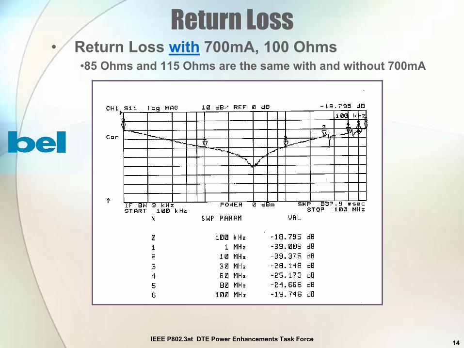
Return Loss• Return Loss with 700mA, 100 Ohms
•85 Ohms and 115 Ohms are the same with and without 700mA

IEEE P802.3at DTE Power Enhancements Task Force 15
Return Loss - Conclusions
• Return Loss does not distort with 700mA• Return Loss does not degrade using
magnetics for 24 mA imbalance design• Return Loss still meets IEEE 802.3
10/100/1000Base-T specifications

IEEE P802.3at DTE Power Enhancements Task Force 16
Phase• Phase with 700mA of current applied to
center tap of transformer

IEEE P802.3at DTE Power Enhancements Task Force 17
Phase• Phase with DC imbalance of 26mA• Conclusion: Phase does not distort with
700mA
IEEE P802.3at DTE Power Enhancements Task Force 18
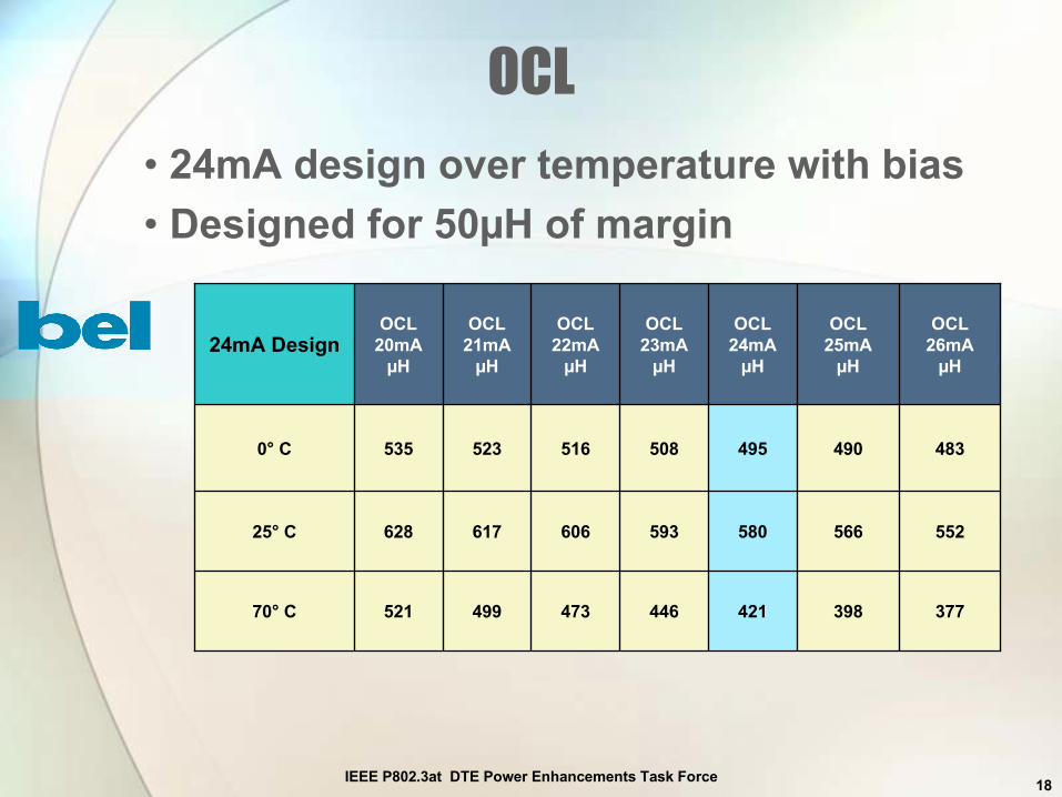
OCL
37739842144647349952170° C
55256658059360661762825° C
4834904955085165235350° C
OCL26mA
µH
OCL25mA
µH
OCL24mA
µH
OCL23mA
µH
OCL22mA
µH
OCL21mA
µH
OCL20mA
µH24mA Design
• 24mA design over temperature with bias• Designed for 50µH of margin

IEEE P802.3at DTE Power Enhancements Task Force 19
OCL
40542446344852170° C
74378983788693525° C
6686756907277600° C
OCL 34mAµH
OCL 33mAµH
OCL 32mAµH
OCL 31mAµH
OCL 30mAµH34mA Design
• 34mA design over temperature with bias• Designed for 50µH of margin

IEEE P802.3at DTE Power Enhancements Task Force 20
Component Power Dissipation vs. Temperature, CalculatedPower Dissipated By Component vs. Operating Temperature, 700mA
0.118
0.115
0.112
0.109
0.106
0.103
0.100
0.097
0.094
0.091
0.000 0.020 0.040 0.060 0.080 0.100 0.120 0.140
25
30
35
40
45
50
55
60
65
70O
pera
ting
Tem
p (°
C)
Power Dissipated By Components (Watt)
IEEE P802.3at DTE Power Enhancements Task Force 21
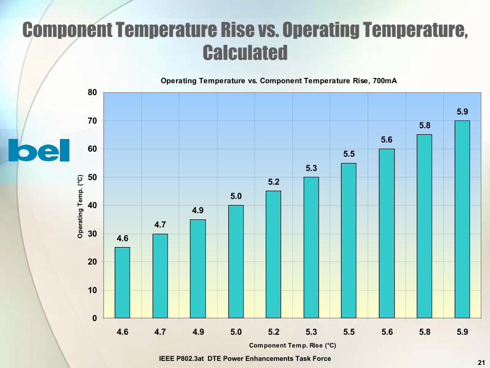
Component Temperature Rise vs. Operating Temperature,Calculated
Operating Temperature vs. Component Temperature Rise, 700mA
4.64.7
4.95.0
5.25.3
5.55.6
5.85.9
0
10
20
30
40
50
60
70
80
4.6 4.7 4.9 5.0 5.2 5.3 5.5 5.6 5.8 5.9Component Temp. Rise (°C)
Ope
ratin
g Te
mp.
(°C
)

IEEE P802.3at DTE Power Enhancements Task Force 22
Component Temperature Rise vsOperating Temperature Measured
• Measured temperature rise of component using 800mA,probe molded into center of magnetics winding area
• Minimal rise seen using 700mA, so increased to 800mA
72.3° C
27.7° C
2.4° C
800mA TemperatureRise0mA
DC Bias
2.9° C69.4° C70° C
2.6° C25.1° C25° C
1.9° C0.5° C0° C
OperatingTemperature

IEEE P802.3at DTE Power Enhancements Task Force 23
Component Size IncreaseDepth Only
% IncreaseDescription
10%
0%
15%
0%
24mA
20%Multi-port, two-pair, 10/100/1000Base-T
0%Multi-port, 10/100Base-T
20%Single port, 10/100/1000Base-T
0%Single port, 10/100Base-T
34mA

IEEE P802.3at DTE Power Enhancements Task Force 24
Conclusions
• 1000Base-T backward compatiblemagnetics are capable ofsupporting 24mA of DC bias
• Distortion with DC bias is not anissue
• Temperature rise is ~ 6° C whenoperating at 70° C and applying800mA of current per port

IEEE P802.3at DTE Power Enhancements Task Force 25
Future Work
• Different circuit topologies need tobe tested
• 1000Base-T backward compatiblemagnetics are capable ofsupporting 34mA of DC bias butrequire further test validation.Insertion Loss, Return Loss anddifferent circuits topologies.

26
Thank you for your time