Magnetics DESIGN - Heynen
26
PARTNER | SOLVE | DELIVER™ PLANAR Magnetics DESIGN
Transcript of Magnetics DESIGN - Heynen

PARTNER | SOLVE | DELIVER™
PLANARM a g n e t i c sDESIGN

2Fill out a design request today! | meder.com/planartransformers.html
DESIGN GUIDE | Planar Transformers & InductorsDESIGN GUIDE | Planar Transformers & Inductors
ENGINEERING
Electronic sensor engineeringCircuit Design and PCB LayoutPatented Conductivity SensorsPatented Inductive Sensors3-D CAD Modeling3-D Magnetic Sensor MappingEMS SoftwarePCB PrototyperQuick Turn Samples, 3-D Printing
TESTING & TOOLING
Automated Assembly and Test SystemsEnvironmental and Durability Testing Life TestingSpecialized Lab Testing Equipment including but not limited to: Network Analyzers, Flux-meters, Nanovoltmeters, Picoammeters, De-structive Pull Testers, Gauss / Teslameters
QUALITY / LAB CAPABILITIES
Certifications: AS9100, ITAR, ISO9000, TS16949, IP67SPC Data CollectionFully Equipped Certified Test LabsBurn-in and Life TestingComplete In-House Machine ShopCorona Discharge Testing CapabilitiesMechanical and Thermal Shock Microscopic Investigation / DPAMoisture Resistance and Seal TestingRadiographic Salt Fog and SolderabilityScott T Angular AccuracyTerminal StrengthThermal CyclingTemperature Rise and Vibration
MANUFACTURING
Auto AT Switch SortingBobbin and Toroidal WindingAuto TerminationCoil Molding & PackagingInsert and Thermoset MoldingLaser WeldingLow Pressure Molding (Hot Melt)Pick & Place – Vision & Camera SystemPlasma Surface TreatmentPlastic Injection MoldingPotting - 2 ComponentProgressive StampingReflow Oven – Multiple Zone ConvectionReed Switch ManufacturingReed Relay Design and Manufacturing - SMD, Low Thermal, High Insulation, High Voltage, High Frequency, Latching and ATEX, Selective SolderingStainless Steel Fabrication
WHAT WE DO
Our team has been providing solutions through high-performing products since the 1950’s. Through growth, acquisition, strategically partnering with customers, and applying the latest engineering designs to the needs of our ever-changing world, our technology has infused transforming results into an array of customer’s needs – ultimately providing quality results to the end-user. Our approach that fuels this is achieved by:
1. Partnering with the customer 2. Confronting a challenge to solve3. Delivering solutions and products that address your needs as a business.
WHAT WE BELIEVE
Our values and what we believe align to the partner, solve, and deliver approach. We produce parts but we are more than that. Connecting with your team as a strategic partner, listening to your challenges, and arriving at ways to solve your complex problems through our solutions are why we exist. Whether it’s custom or standard we have capabilities that address your needs. Our team leverages our dynamic and diverse engineering expertise and other resources such as our global facilities for logistics and production.
CAPABILITIES
Standex-Meder Electronics has a commitment to absolute customer satisfaction and customer-driven innovation, with a global organization that offers premier sales support, engineering capabilities, and technical resources worldwide. At Standex-Meder Electronics, customer-specific product development has never been a problem. With our expert engineering staff and cutting-edge manufacturing capabilities, we are well-equipped to produce unique solutions for just about any environment or application.
3Fill out a design request today! | meder.com/planartransformers.html
DESIGN GUIDE | Planar Transformers & InductorsDESIGN GUIDE | Planar Transformers & Inductors
• Large core surface promotes heat transfer• Low loss, reliable PCB construction • AC Resistance and Proximity Cu Loss Minimized
APPLICATIONS• AC-DC resonant designs • Aerospace & Military (high reliability/repeatability) • Appliance• Automotive, Electric and Hybrid Vehicles• Battery Charging (12V, 24V, 48V, 1-10 KW) • DC-DC Converters (100W-1200W) in distributed power systems• Distributed Isolated Power• Feedback Control• High Current POL Converters• High Power LED Lighting, Industrial Power, Welding• Isolated Inverters• Isolated (non-regulated) Bus Converter (Vout 9-12V)• Renewable Energy - Wind & Photovoltaic Power System• Server – Data Centers (400VDC)• Telecom Applications (“Sweet Spot” 36-72 Vin 40-250W)• Welding, Lasers, Test Equipment
STANDEX-MEDER UNIQUE ADVANTAGES• Patented (U.S. PAT. 7,129,809) header and terminal (U.S. PAT.
7,460,002) design yielding superior thermal management• Direct thermal contact between bottom of ferrite core and heat
dissipating substrate• Can attach to a substrate/heatsink with controlled temperature• Stable and precise co-planarity of terminals on both sides• Excellent solderability characteristics• Planar turn surface in direct contact core backwall, thus greatly
improving thermal conductivity and reducing EMI• Flexible, low impedance terminations• Able operate without any air flow for cooling• Meets required min. 8mm clearance and creepage
ELECTRICAL & MECHANICAL SPECS• Height - low profile• Low leakage inductance• Repeatable leakage inductance, capacitance• Volumetric efficiency (small size)• Low turns count improves Cu loss• Optimized core cross section lowers core loss
“CUSTOM IS STANDARD” - Why SME Planar Transformers & Inductors?
As more and more industries begin to feel the push toward higher efficiency and performance along with miniaturization, the planar transformer continues to emerge as an alternative to wire-wound transformers, making it ideal in certain application “sweet spots”. This solution makes so much sense for today’s applications, and when you combine planar transformers with excellent engineering, you can get a solution that not only saves you space, time, and costs, but suits your needs uniquely and specifically. We are your “Application Engineering Experts”.
The unique P025 - P1100 product line of planar transformers come in standard sizes and with hundreds of lead frames and PCB windings in stock, they can be quickly customized often without start-up or tooling costs for many power topologies, including soft switching, single or multiple outputs, different switching frequencies, and different input/output voltages as well as multi-winding inductors. Refer to the below Custom Design Guide Overview.
Size Page Optimum Max Typical Optimum Typical Dimensions Isolation Voltage# Power Current Topology Frequency L x W x H (1) Pri - Sec (VDC)
Range Rating Range kHZ mm Pri - Core (VDC)
P025 (3) 6 10W - 50W 20A (2) Forward, Flyback 300 - 500 17.0 x 15.7 x 6.3 500 - 2000 VDC
P035 (3) 7 20W - 150W 30A (2) Half Bridge, Forward, Flyback 200 - 400 22.9 x 19.8 x 7.6 500 - 2000 VDC
P055 (3) 8 50W - 200W 50A Half Bridge, Forward, Flyback 175 - 300 24.1 x 21.8 x 9.1 500 - 2000 VDC
P075 (3) 9 100W - 500W 50A (2)Full Bridge, Half Bridge, Full Bridge ZVS, Push-Pull, Flyback
150 - 30035.0 x 26.3 x 10.228.7 x 26.3 x 10.2
5000 VDC500 - 2000 VDC
P110 (3) 10 150W - 700W 60A (2)Full Bridge, Half Bridge, Full Bridge ZVS, Push-Pull
100 - 25039.9 x 28.4 x 12.733.5 x 28.4 x 12.7
5000 VDC500 - 2000 VDC
P135 11-12 300W - 1.2kW 100AFull Bridge, Half Bridge, Full Bridge ZVS, Push-Pull
100 - 25044.4 x 32.0 x 15.238.1 x 32.0 x 12.7
5000 VDC500 - 2000 VDC
P220 13-14 1kW - 3.0kW 250AFull Bridge, Half Bridge, Full Bridge ZVS, Push-Pull
60 - 20050.8 x 40.6 x 20.345.7 x 40.6 x 17.8
5000 VDC500 - 2000 VDC
P350 15-16 2kW - 6kW 300AFull Bridge, Half Bridge, Full Bridge ZVS, Push-Pull
40 - 15058.4 x 50.8 x 25.453.3 x 50.8 x 21.6
5000 VDC500 - 2000 VDC
P560 17-18 3kW - 10kW 400AFull Bridge, Half Bridge, Full Bridge ZVS, Push-Pull
40 - 12571.1 x 64.0 x 30.566.0 x 64.0 x 25.4
5000 VDC500 - 2000 VDC
P900 19-20 10kW - 20kW 500AFull Bridge, Half Bridge, Full Bridge ZVS, Push-Pull
40 - 125 118.1 x 110.7 x 43.9 5000 VDC
P1100 21 10kW - 30kW 600AFull Bridge, Half Bridge, Full Bridge ZVS, Push-Pull
20 - 125 144.8 x 94.0 x 38.1 5000 VDC
1) Length (L) may vary depending on terminals. Height (H) may vary depending on input / output requirements2) Current rating is 30% higher for through hole applications3) Available in both SMD and through hole versions
Planar Magnetics Custom Design Guide
4Fill out a design request today! | meder.com/planartransformers.html
DESIGN GUIDE | Planar Transformers & InductorsDESIGN GUIDE | Planar Transformers & Inductors
5Fill out a design request today! | meder.com/planartransformers.html
DESIGN GUIDE | Planar Transformers & InductorsDESIGN GUIDE | Planar Transformers & Inductors
6Fill out a design request today! | meder.com/planartransformers.html
These models are for reference only and may NOT exactly match the design examples provided.
8.1 mm
max
19.1 mm
15.8 mm
U.S. PAT. 7,129,809
DESIGN GUIDE | Planar Transformers & InductorsDESIGN GUIDE | Planar Transformers & Inductors
SURFACE MOUNT DESIGN
Customize beyond these examples!
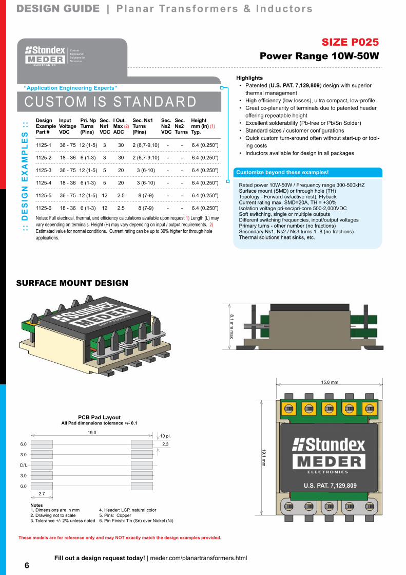
Rated power 10W-50W / Frequency range 300-500kHZSurface mount (SMD) or through hole (TH)Topology - Forward (w/active rest), FlybackCurrent rating max. SMD=20A, TH = +30%Isolation voltage pri-sec/pri-core 500-2,000VDCSoft switching, single or multiple outputsDifferent switching frequencies, input/output voltagesPrimary turns - other number (no fractions)Secondary Ns1, Ns2 / Ns3 turns 1- 8 (no fractions)Thermal solutions heat sinks, etc.
Highlights• Patented (U.S. PAT. 7,129,809) design with superior
thermal management• High efficiency (low losses), ultra compact, low-profile• Great co-planarity of terminals due to patented header
offering repeatable height• Excellent solderability (Pb-free or Pb/Sn Solder)• Standard sizes / customer configurations• Quick custom turn-around often without start-up or tool-
ing costs• Inductors available for design in all packages
19.010 pl.
6.0 2.3
3.0
C/L
3.0
6.0
2.7
PCB Pad LayoutAll Pad dimensions tolerance +/- 0.1
Notes1. Dimensions are in mm2. Drawing not to scale3. Tolerance +/- 2% unless noted
4. Header: LCP, natural color5. Pins: Copper6. Pin Finish: Tin (Sn) over Nickel (Ni)
SIZE P025Power Range 10W-50W
:: D
ES
IGN
EX
AM
PL
ES
:: Design Input Pri. Np Sec. I Out. Sec. Ns1 Sec. Sec. Height
Example Voltage Turns Ns1 Max (2) Turns Ns2 Ns2 mm (in) (1)Part # VDC (Pins) VDC ADC (Pins) VDC Turns Typ.
1125-1 36 - 75 12 (1-5) 3 30 2 (6,7-9,10) - - 6.4 (0.250”)
1125-2 18 - 36 6 (1-3) 3 30 2 (6,7-9,10) - - 6.4 (0.250”)
1125-3 36 - 75 12 (1-5) 5 20 3 (6-10) - - 6.4 (0.250”)
1125-4 18 - 36 6 (1-3) 5 20 3 (6-10) - - 6.4 (0.250”)
1125-5 36 - 75 12 (1-5) 12 2.5 8 (7-9) - - 6.4 (0.250”)
1125-6 18 - 36 6 (1-3) 12 2.5 8 (7-9) - - 6.4 (0.250”)
Notes: Full electrical, thermal, and efficiency calculations available upon request 1) Length (L) may vary depending on terminals. Height (H) may vary depending on input / output requirements. 2) Estimated value for normal conditions. Current rating can be up to 30% higher for through hole applications.
CUSTOM IS S TA N D A R D
“Application Engineering Experts”
7Fill out a design request today! | meder.com/planartransformers.html
These models are for reference only and may NOT exactly match the design examples provided.
8.6 mm
max
U.S. PAT. 7,129,809
26.7 mm
19.8 mm
DESIGN GUIDE | Planar Transformers & InductorsDESIGN GUIDE | Planar Transformers & Inductors
29.214 pl.
8.4 2.3
5.1
2.5
C/L
2.5
5.1
8.4
5.0
PCB Pad LayoutAll Pad dimensions tolerance +/- 0.1
Notes1. Dimensions are in mm2. Drawing not to scale3. Tolerance +/- 2% unless noted
4. Header: LCP, natural color5. Pins: Copper6. Pin Finish: Tin (Sn) over Nickel (Ni)
SURFACE MOUNT DESIGN
Customize beyond these examples!
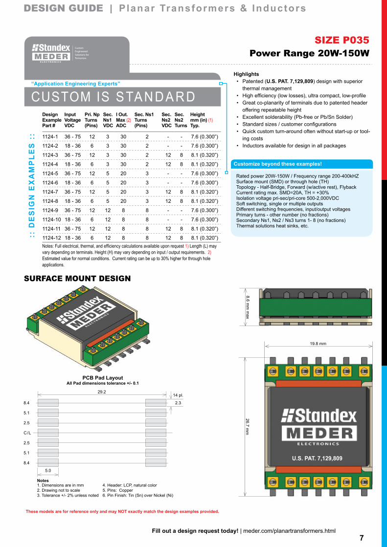
Rated power 20W-150W / Frequency range 200-400kHZSurface mount (SMD) or through hole (TH)Topology - Half-Bridge, Forward (w/active rest), FlybackCurrent rating max. SMD=20A, TH = +30%Isolation voltage pri-sec/pri-core 500-2,000VDCSoft switching, single or multiple outputsDifferent switching frequencies, input/output voltagesPrimary turns - other number (no fractions)Secondary Ns1, Ns2 / Ns3 turns 1- 8 (no fractions)Thermal solutions heat sinks, etc.
Highlights• Patented (U.S. PAT. 7,129,809) design with superior
thermal management• High efficiency (low losses), ultra compact, low-profile• Great co-planarity of terminals due to patented header
offering repeatable height• Excellent solderability (Pb-free or Pb/Sn Solder)• Standard sizes / customer configurations• Quick custom turn-around often without start-up or tool-
ing costs• Inductors available for design in all packages
SIZE P035Power Range 20W-150W
::
DE
SIG
N E
XA
MP
LE
S :
:
Design Input Pri. Np Sec. I Out. Sec. Ns1 Sec. Sec. HeightExample Voltage Turns Ns1 Max (2) Turns Ns2 Ns2 mm (in) (1)Part # VDC (Pins) VDC ADC (Pins) VDC Turns Typ.
1124-1 36 - 75 12 3 30 2 - - 7.6 (0.300”)
1124-2 18 - 36 6 3 30 2 - - 7.6 (0.300”)
1124-3 36 - 75 12 3 30 2 12 8 8.1 (0.320”)
1124-4 18 - 36 6 3 30 2 12 8 8.1 (0.320”)
1124-5 36 - 75 12 5 20 3 - - 7.6 (0.300”)
1124-6 18 - 36 6 5 20 3 - - 7.6 (0.300”)
1124-7 36 - 75 12 5 20 3 12 8 8.1 (0.320”)
1124-8 18 - 36 6 5 20 3 12 8 8.1 (0.320”)
1124-9 36 - 75 12 12 8 8 - - 7.6 (0.300”)
1124-10 18 - 36 6 12 8 8 - - 7.6 (0.300”)
1124-11 36 - 75 12 12 8 8 12 8 8.1 (0.320”)
1124-12 18 - 36 6 12 8 8 12 8 8.1 (0.320”)Notes: Full electrical, thermal, and efficiency calculations available upon request 1) Length (L) may vary depending on terminals. Height (H) may vary depending on input / output requirements. 2) Estimated value for normal conditions. Current rating can be up to 30% higher for through hole applications.
CUSTOM IS S TA N D A R D
“Application Engineering Experts”
8Fill out a design request today! | meder.com/planartransformers.html
These models are for reference only and may NOT exactly match the design examples provided.
11.2 mm
max
26.7 mm
21.8 mm
U.S. PAT. 7,129,809
DESIGN GUIDE | Planar Transformers & InductorsDESIGN GUIDE | Planar Transformers & Inductors
SURFACE MOUNT DESIGN
30.514 pl.
9.0 2.3
6.0
3.0
C/L
3.0
6.0
9.0
5.1
PCB Pad LayoutAll Pad dimensions tolerance +/- 0.1
Notes1. Dimensions are in mm2. Drawing not to scale3. Tolerance +/- 2% unless noted
4. Header: LCP, natural color5. Pins: Copper6. Pin Finish: Tin (Sn) over Nickel (Ni)
Customize beyond these examples!
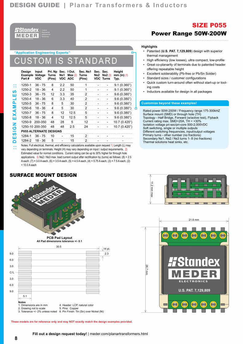
Rated power 50W-200W / Frequency range 175-300kHZSurface mount (SMD) or through hole (TH)Topology - Half Bridge, Forward (w/active rest), FlybackCurrent rating max. SMD=20A, TH = +30%Isolation voltage pri-sec/pri-core 500-2,000VDCSoft switching, single or multiple outputsDifferent switching frequencies, input/output voltagesPrimary turns - other number (no fractions)Secondary Ns1, Ns2 / Ns3 turns 1- 8 (no fractions)Thermal solutions heat sinks, etc.
Highlights• Patented (U.S. PAT. 7,129,809) design with superior
thermal management• High efficiency (low losses), ultra compact, low-profile• Great co-planarity of terminals due to patented header
offering repeatable height• Excellent solderability (Pb-free or Pb/Sn Solder)• Standard sizes / customer configurations• Quick custom turn-around often without start-up or tool-
ing costs• Inductors available for design in all packages
SIZE P055Power Range 50W-200W
:: D
ES
IGN
EX
AM
PL
ES
::
Design Input Pri. Np Sec. I Out. Sec. Ns1 Sec. Sec. HeightExample Voltage Turns Ns1 Max (2) Turns Ns2 Ns2 (3) mm (in) (1)Part # VDC (Pins) VDC ADC (Pins) VDC Turns Typ.
1250-1 36 - 75 8 2.2 50 1 - - 9.1 (0.360”)1250-2 18 - 36 4 2.2 50 1 - - 9.1 (0.360”)1250-3 36 - 75 12 3.3 35 2 - - 9.6 (0.380”)1250-4 18 - 36 6 3.3 40 2 - - 9.6 (0.380”)1250-5 36 - 75 8 5 30 2 - - 9.6 (0.380”)1250-6 18 - 36 4 5 30 2 - - 9.6 (0.380”)1250-7 36 - 75 8 12 12.5 5 - - 9.6 (0.380”)1250-8 18 - 36 4 12 12.5 5 - - 9.6 (0.380”)1250-9 200-350 48 28 5 12 - - 10.7 (0.420”)1250-10 200-350 48 48 2.5 24 - - 10.7 (0.420”)P055 ALTERNATE DESIGNS1284-1 36 - 75 10 - 15 2 - - -1284-2 18 - 36 5 - 15 2 - - -Notes: Full electrical, thermal, and efficiency calculations available upon request 1) Length (L) may vary depending on terminals. Height (H) may vary depending on input / output requirements. 2) Estimated value for normal conditions. Current rating can be up to 30% higher for through hole applications. 3) Ns2 / Ns3 max. load current output after rectification by (turns) as follows: (8) = 2.5 A each, (7) = 3.0 A each, (6) = 3.5 A each, (5) = 4.5 A each, (4) = 5.75 A each, (3) = 7.5 A each, (2) = 10.0 A each
CUSTOM IS S TA N D A R D
“Application Engineering Experts”
9Fill out a design request today! | meder.com/planartransformers.html
These models are for reference only and may NOT exactly match the design examples provided.
10.7 mm
max
33.0 mm
26.4 mm
U.S. PAT. 7,129,809
DESIGN GUIDE | Planar Transformers & InductorsDESIGN GUIDE | Planar Transformers & Inductors
PCB Pad LayoutAll Pad dimensions tolerance +/- 0.1
33.014 pl.
10.2 1.3
6.8
3.4
C/L
3.4
6.8
10.2
4.4
Notes1. Dimensions are in mm2. Drawing not to scale3. Tolerance +/- 2% unless noted
4. Header: LCP, natural color5. Pins: Copper6. Pin Finish: Tin (Sn) over Nickel (Ni)
SURFACE MOUNT DESIGN
Customize beyond these examples!
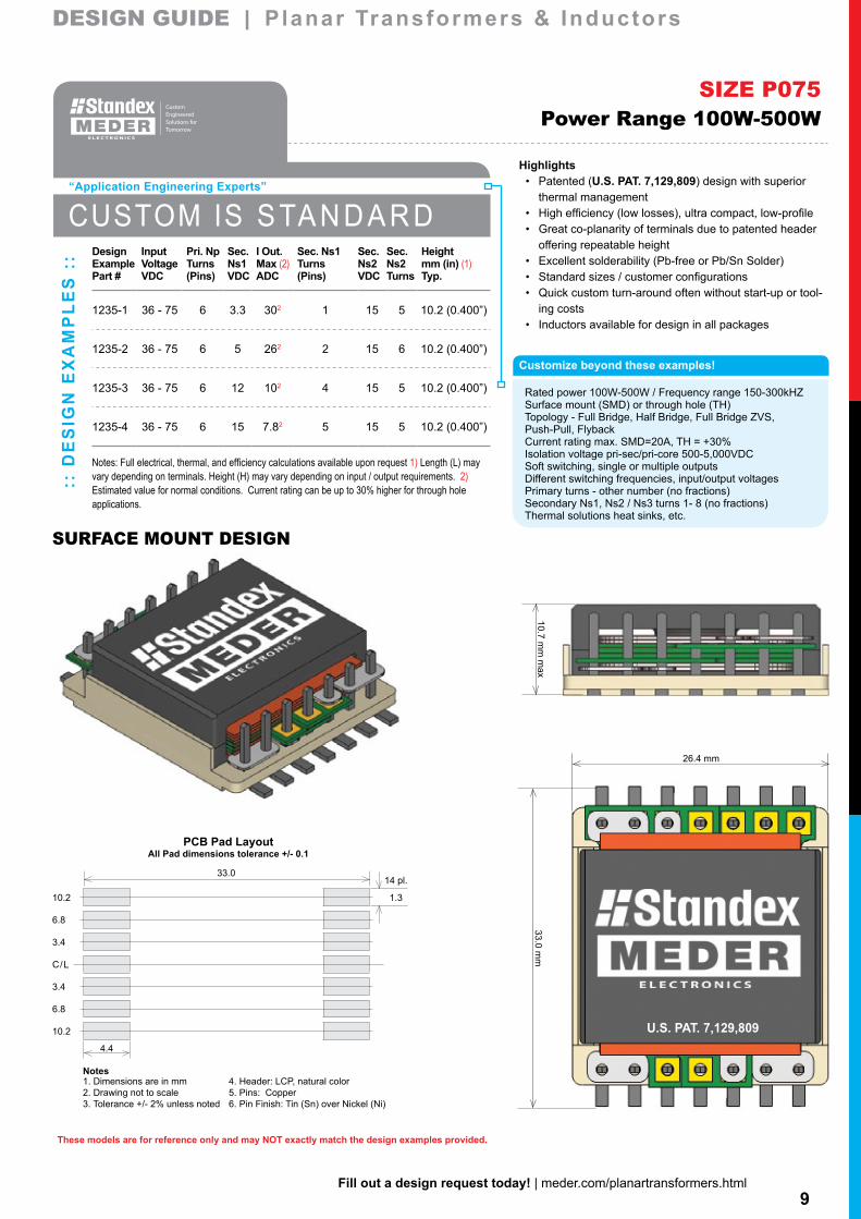
Rated power 100W-500W / Frequency range 150-300kHZSurface mount (SMD) or through hole (TH)Topology - Full Bridge, Half Bridge, Full Bridge ZVS, Push-Pull, FlybackCurrent rating max. SMD=20A, TH = +30%Isolation voltage pri-sec/pri-core 500-5,000VDCSoft switching, single or multiple outputsDifferent switching frequencies, input/output voltagesPrimary turns - other number (no fractions)Secondary Ns1, Ns2 / Ns3 turns 1- 8 (no fractions)Thermal solutions heat sinks, etc.
Highlights• Patented (U.S. PAT. 7,129,809) design with superior
thermal management• High efficiency (low losses), ultra compact, low-profile• Great co-planarity of terminals due to patented header
offering repeatable height• Excellent solderability (Pb-free or Pb/Sn Solder)• Standard sizes / customer configurations• Quick custom turn-around often without start-up or tool-
ing costs• Inductors available for design in all packages
SIZE P075Power Range 100W-500W
:: D
ES
IGN
EX
AM
PL
ES
:: Design Input Pri. Np Sec. I Out. Sec. Ns1 Sec. Sec. Height
Example Voltage Turns Ns1 Max (2) Turns Ns2 Ns2 mm (in) (1)Part # VDC (Pins) VDC ADC (Pins) VDC Turns Typ.
1235-1 36 - 75 6 3.3 302 1 15 5 10.2 (0.400”)
1235-2 36 - 75 6 5 262 2 15 6 10.2 (0.400”)
1235-3 36 - 75 6 12 102 4 15 5 10.2 (0.400”)
1235-4 36 - 75 6 15 7.82 5 15 5 10.2 (0.400”)
Notes: Full electrical, thermal, and efficiency calculations available upon request 1) Length (L) may vary depending on terminals. Height (H) may vary depending on input / output requirements. 2) Estimated value for normal conditions. Current rating can be up to 30% higher for through hole applications.
CUSTOM IS S TA N D A R D
“Application Engineering Experts”

10Fill out a design request today! | meder.com/planartransformers.html
These models are for reference only and may NOT exactly match the design examples provided.
13.5 mm
max
39.1 mm
30.5 mm
U.S. PAT. 7,129,809
DESIGN GUIDE | Planar Transformers & InductorsDESIGN GUIDE | Planar Transformers & Inductors
40.218 pl.
12.0 2.3
9.0
core bonding area
6.0
3.0
C/L
3.0
6.0
9.0
12.0
6.3
PCB Pad LayoutAll Pad dimensions tolerance +/- 0.1
Notes1. Dimensions are in mm2. Drawing not to scale3. Tolerance +/- 2% unless noted
4. Header: LCP, natural color5. Pins: Copper6. Pin Finish: Tin (Sn) over Nickel (Ni)
SURFACE MOUNT DESIGN
Customize beyond these examples!
Rated power 150W-700W / Frequency range 175-300kHZSurface mount (SMD) or through hole (TH)Topology - Full Bridge, Half Bridge, Full Bridge ZVS, Push-Pull, FlybackCurrent rating max. SMD=20A, TH = +30%Isolation voltage pri-sec/pri-core 500-5,000VDCSoft switching, single or multiple outputsDifferent switching frequencies, input/output voltagesPrimary turns - other number (no fractions)Secondary Ns1, Ns2 / Ns3 turns 1- 8 (no fractions)Thermal solutions heat sinks, etc.
Highlights• Patented (U.S. PAT. 7,129,809) design with superior
thermal management• High efficiency (low losses), ultra compact, low-profile• Great co-planarity of terminals due to patented header
offering repeatable height• Excellent solderability (Pb-free or Pb/Sn Solder)• Standard sizes / customer configurations• Quick custom turn-around often without start-up or tool-
ing costs• Inductors available for design in all packages
SIZE P110Power Range 150W-700W
CUSTOM IS S TA N D A R D
:: D
ES
IGN
EX
AM
PL
ES
:: Design Input Pri. Np Sec. I Out. Sec. Ns1 Sec. Sec. Height
Example Voltage Turns Ns1 Max (2) Turns Ns2 Ns2 mm (in) (1)Part # VDC (Pins) VDC ADC (Pins) VDC Turns Typ.
1240-1 190-350 16 2.2 152 3 - - 12.7(0.500”)
1240-2 190-350 24 2.2 272 2 24 4 12.7(0.500”)
1240-3 190-350 28 3.3 462 1 15 3 12.7(0.500”)
1240-4 190-350 16 3.3 102 5 - - 12.7(0.500”)
1240-5 190-350 20 5 272 2 15 2 12.7(0.500”)
Notes: Full electrical, thermal, and efficiency calculations available upon request 1) Length (L) may vary depending on terminals. Height (H) may vary depending on input / output requirements. 2) Estimated value for normal conditions. Current rating can be up to 30% higher for through hole applications.
“Application Engineering Experts”

11Fill out a design request today! | meder.com/planartransformers.html
These models are for reference only and may NOT exactly match the design examples provided.
15.7 mm
43.0 mm
32.1 mm
22.9 mm
2.5 mm
DESIGN GUIDE | Planar Transformers & InductorsDESIGN GUIDE | Planar Transformers & Inductors
THROUGH HOLE / J-HOOK MOUNT
Customize beyond these examples!
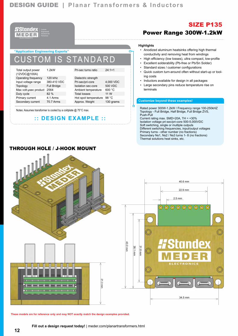
Rated power 300W-1.2kW / Frequency range 100-250kHZTopology - Full Bridge, Half Bridge, Full Bridge ZVS, Push-PullCurrent rating max. SMD=20A, TH = +30%Isolation voltage pri-sec/pri-core 500-5,000VDCSoft switching, single or multiple outputsDifferent switching frequencies, input/output voltagesPrimary turns - other number (no fractions)Secondary Ns1, Ns2 / Ns3 turns 1- 8 (no fractions)Thermal solutions heat sinks, etc.
Highlights• High efficiency (low losses), ultra compact, low-profile• Excellent solderability (Pb-free or Pb/Sn Solder)• Standard sizes / customer configurations• Quick custom turn-around often without start-up or tool-
ing costs• Inductors available for design in all packages• Large secondary pins reduce temperature rise on
terminals
SIZE P135Power Range 300W-1.2kW
CUSTOM IS S TA N D A R D
: : DESIGN EXAMPLE ::
“Application Engineering Experts”
Pri-sec turns ratio 20:1+1
Dielectric strengthPri-sec/pri-core 4,000 VDCIsolation sec-core 500 VDCAmbient temperature 60 °CTotal losses 6.0 WHot spot temperature 108 °CApprox. Weight 100 grams
Total output power 600W(12VDC@50A)Operating frequency 200 kHzInput voltage range 370-410 VDCTopology Full Bridge ZVSMax volt-µsec product 1216Duty cycle 66 %Primary current 2.9 ArmsSecondary current 35.4 Arms
Notes: Assumes transformer is cooled by airflow only @ 200°C LFM
12Fill out a design request today! | meder.com/planartransformers.html
These models are for reference only and may NOT exactly match the design examples provided.
21.3 mm
34.5 mm
31.8 mm
43.0 mm
40.6 mm
38.1 mm
22.9 mm
2.5 mm
DESIGN GUIDE | Planar Transformers & InductorsDESIGN GUIDE | Planar Transformers & Inductors
THROUGH HOLE / J-HOOK MOUNT
Customize beyond these examples!
Rated power 300W-1.2kW / Frequency range 100-250kHZTopology - Full Bridge, Half Bridge, Full Bridge ZVS, Push-PullCurrent rating max. SMD=20A, TH = +30%Isolation voltage pri-sec/pri-core 500-5,000VDCSoft switching, single or multiple outputsDifferent switching frequencies, input/output voltagesPrimary turns - other number (no fractions)Secondary Ns1, Ns2 / Ns3 turns 1- 8 (no fractions)Thermal solutions heat sinks, etc.
Highlights• Anodized aluminum heatsinks offering high thermal
conductivity and removing heat from windings• High efficiency (low losses), ultra compact, low-profile• Excellent solderability (Pb-free or Pb/Sn Solder)• Standard sizes / customer configurations• Quick custom turn-around often without start-up or tool-
ing costs• Inductors available for design in all packages• Large secondary pins reduce temperature rise on
terminals
SIZE P135Power Range 300W-1.2kW
CUSTOM IS S TA N D A R D
: : DESIGN EXAMPLE ::
“Application Engineering Experts”
Pri-sec turns ratio 24:1+1
Dielectric strengthPri-sec/pri-core 4,000 VDCIsolation sec-core 500 VDCAmbient temperature 600 °CTotal losses 11 WHot spot temperature 98 °CApprox. Weight 130 grams
Total output power 1.2kW(12VDC@100A)Operating frequency 120 kHzInput voltage range 380-410 VDCTopology Full BridgeMax volt-µsec product 2564Duty cycle 82 %Primary current 4.1 ArmsSecondary current 70.7 Arms
Notes: Assumes transformer is cooled by a coldplate @ 75°C max.
13Fill out a design request today! | meder.com/planartransformers.html
These models are for reference only and may NOT exactly match the design examples provided.
16.6 mm
40.6 mm
52.0 mm
30.5 mm
3.8 mm
DESIGN GUIDE | Planar Transformers & InductorsDESIGN GUIDE | Planar Transformers & Inductors
THROUGH HOLE / J-HOOK MOUNT
Customize beyond these examples!
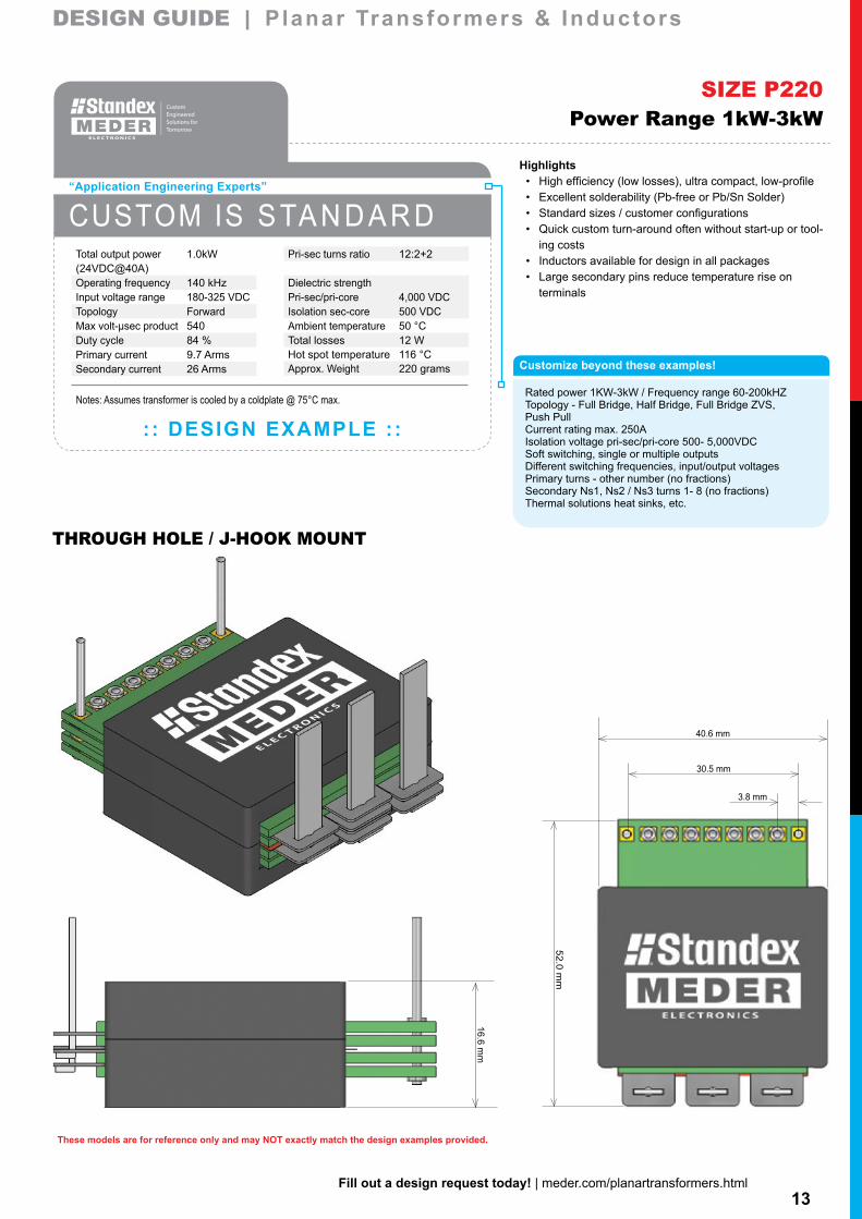
Rated power 1KW-3kW / Frequency range 60-200kHZTopology - Full Bridge, Half Bridge, Full Bridge ZVS,Push PullCurrent rating max. 250AIsolation voltage pri-sec/pri-core 500- 5,000VDCSoft switching, single or multiple outputsDifferent switching frequencies, input/output voltagesPrimary turns - other number (no fractions)Secondary Ns1, Ns2 / Ns3 turns 1- 8 (no fractions)Thermal solutions heat sinks, etc.
Highlights• High efficiency (low losses), ultra compact, low-profile• Excellent solderability (Pb-free or Pb/Sn Solder)• Standard sizes / customer configurations• Quick custom turn-around often without start-up or tool-
ing costs• Inductors available for design in all packages• Large secondary pins reduce temperature rise on
terminals
SIZE P220Power Range 1kW-3kW
CUSTOM IS S TA N D A R D
: : DESIGN EXAMPLE ::
“Application Engineering Experts”
Pri-sec turns ratio 12:2+2
Dielectric strengthPri-sec/pri-core 4,000 VDCIsolation sec-core 500 VDCAmbient temperature 50 °CTotal losses 12 WHot spot temperature 116 °CApprox. Weight 220 grams
Total output power 1.0kW(24VDC@40A)Operating frequency 140 kHzInput voltage range 180-325 VDCTopology ForwardMax volt-µsec product 540Duty cycle 84 %Primary current 9.7 ArmsSecondary current 26 Arms
Notes: Assumes transformer is cooled by a coldplate @ 75°C max.
14Fill out a design request today! | meder.com/planartransformers.html
These models are for reference only and may NOT exactly match the design examples provided.
22.4 mm
42.2 mm
42.2 mm
52.0 mm
30.5 mm
3.8 mm
DESIGN GUIDE | Planar Transformers & InductorsDESIGN GUIDE | Planar Transformers & Inductors
THROUGH HOLE / J-HOOK MOUNT
Customize beyond these examples!
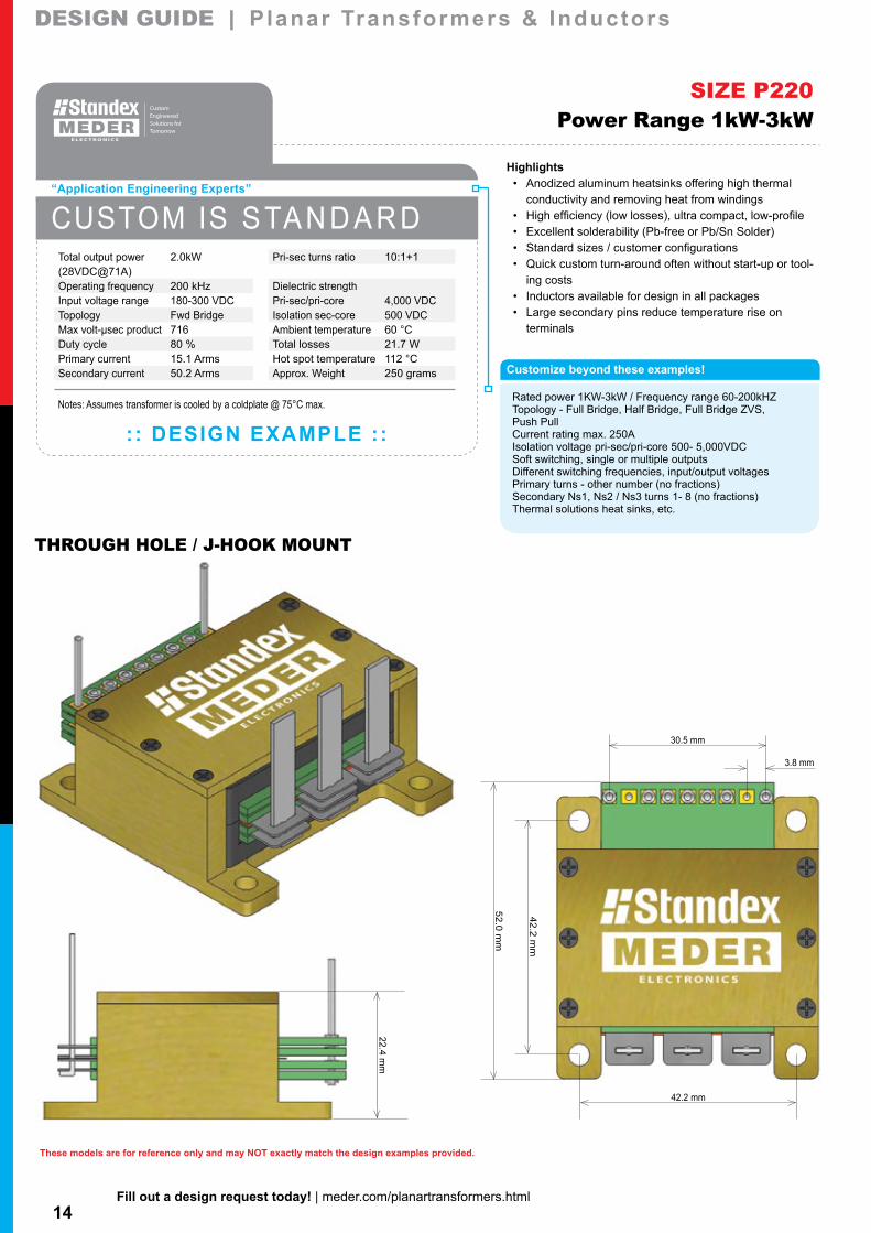
Rated power 1KW-3kW / Frequency range 60-200kHZTopology - Full Bridge, Half Bridge, Full Bridge ZVS,Push PullCurrent rating max. 250AIsolation voltage pri-sec/pri-core 500- 5,000VDCSoft switching, single or multiple outputsDifferent switching frequencies, input/output voltagesPrimary turns - other number (no fractions)Secondary Ns1, Ns2 / Ns3 turns 1- 8 (no fractions)Thermal solutions heat sinks, etc.
Highlights• Anodized aluminum heatsinks offering high thermal
conductivity and removing heat from windings• High efficiency (low losses), ultra compact, low-profile• Excellent solderability (Pb-free or Pb/Sn Solder)• Standard sizes / customer configurations• Quick custom turn-around often without start-up or tool-
ing costs• Inductors available for design in all packages• Large secondary pins reduce temperature rise on
terminals
SIZE P220Power Range 1kW-3kW
CUSTOM IS S TA N D A R D
: : DESIGN EXAMPLE ::
“Application Engineering Experts”
Pri-sec turns ratio 10:1+1
Dielectric strengthPri-sec/pri-core 4,000 VDCIsolation sec-core 500 VDCAmbient temperature 60 °CTotal losses 21.7 WHot spot temperature 112 °CApprox. Weight 250 grams
Total output power 2.0kW(28VDC@71A)Operating frequency 200 kHzInput voltage range 180-300 VDCTopology Fwd BridgeMax volt-µsec product 716Duty cycle 80 %Primary current 15.1 ArmsSecondary current 50.2 Arms
Notes: Assumes transformer is cooled by a coldplate @ 75°C max.
15Fill out a design request today! | meder.com/planartransformers.html
These models are for reference only and may NOT exactly match the design examples provided.
22.9 mm
74.2 mm
40.6 mm
51.0 mm
5.1 mm
U.S. PAT. 7,460,002
DESIGN GUIDE | Planar Transformers & InductorsDESIGN GUIDE | Planar Transformers & Inductors
BUS BAR TERMINATION
Customize beyond these examples!
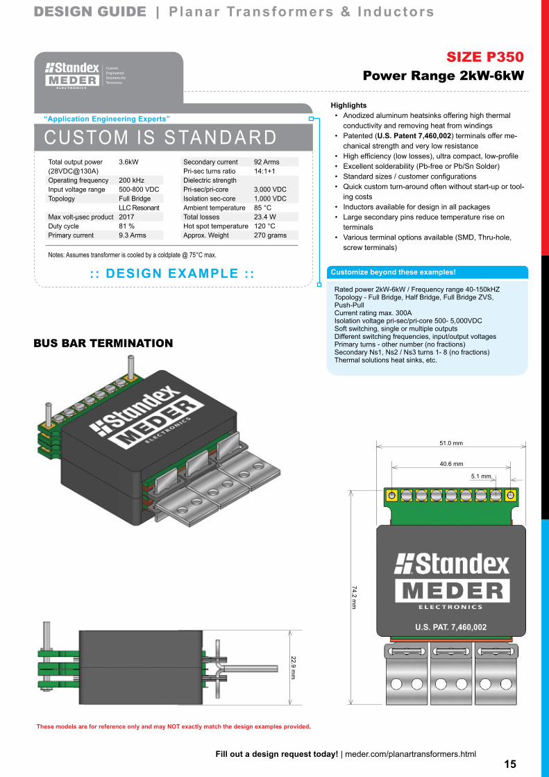
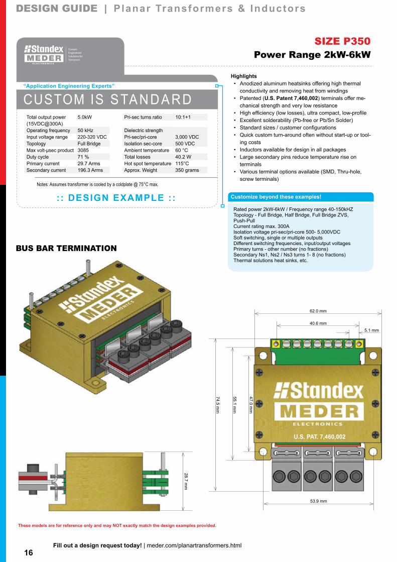
Rated power 2kW-6kW / Frequency range 40-150kHZTopology - Full Bridge, Half Bridge, Full Bridge ZVS,Push-PullCurrent rating max. 300AIsolation voltage pri-sec/pri-core 500- 5,000VDCSoft switching, single or multiple outputsDifferent switching frequencies, input/output voltagesPrimary turns - other number (no fractions)Secondary Ns1, Ns2 / Ns3 turns 1- 8 (no fractions)Thermal solutions heat sinks, etc.
Highlights• Anodized aluminum heatsinks offering high thermal
conductivity and removing heat from windings• Patented (U.S. Patent 7,460,002) terminals offer me-
chanical strength and very low resistance• High efficiency (low losses), ultra compact, low-profile• Excellent solderability (Pb-free or Pb/Sn Solder)• Standard sizes / customer configurations• Quick custom turn-around often without start-up or tool-
ing costs• Inductors available for design in all packages• Large secondary pins reduce temperature rise on
terminals• Various terminal options available (SMD, Thru-hole,
screw terminals)
SIZE P350Power Range 2kW-6kW
CUSTOM IS S TA N D A R D
: : DESIGN EXAMPLE ::
“Application Engineering Experts”
Secondary current 92 ArmsPri-sec turns ratio 14:1+1Dielectric strengthPri-sec/pri-core 3,000 VDCIsolation sec-core 1,000 VDCAmbient temperature 85 °CTotal losses 23.4 WHot spot temperature 120 °CApprox. Weight 270 grams
Total output power 3.6kW(28VDC@130A)Operating frequency 200 kHzInput voltage range 500-800 VDCTopology Full Bridge
LLC ResonantMax volt-µsec product 2017Duty cycle 81 %Primary current 9.3 Arms
Notes: Assumes transformer is cooled by a coldplate @ 75°C max.
16Fill out a design request today! | meder.com/planartransformers.html
These models are for reference only and may NOT exactly match the design examples provided.
28.7 mm
53.9 mm
55.1 mm
74.5 mm
47.0 mm
40.6 mm
62.0 mm
5.1 mm
U.S. PAT. 7,460,002
DESIGN GUIDE | Planar Transformers & InductorsDESIGN GUIDE | Planar Transformers & Inductors
BUS BAR TERMINATION
Customize beyond these examples!
Rated power 2kW-6kW / Frequency range 40-150kHZTopology - Full Bridge, Half Bridge, Full Bridge ZVS,Push-PullCurrent rating max. 300AIsolation voltage pri-sec/pri-core 500- 5,000VDCSoft switching, single or multiple outputsDifferent switching frequencies, input/output voltagesPrimary turns - other number (no fractions)Secondary Ns1, Ns2 / Ns3 turns 1- 8 (no fractions)Thermal solutions heat sinks, etc.
Highlights• Anodized aluminum heatsinks offering high thermal
conductivity and removing heat from windings• Patented (U.S. Patent 7,460,002) terminals offer me-
chanical strength and very low resistance• High efficiency (low losses), ultra compact, low-profile• Excellent solderability (Pb-free or Pb/Sn Solder)• Standard sizes / customer configurations• Quick custom turn-around often without start-up or tool-
ing costs• Inductors available for design in all packages• Large secondary pins reduce temperature rise on
terminals• Various terminal options available (SMD, Thru-hole,
screw terminals)
SIZE P350Power Range 2kW-6kW
CUSTOM IS S TA N D A R D
: : DESIGN EXAMPLE ::
“Application Engineering Experts”
Pri-sec turns ratio 10:1+1
Dielectric strengthPri-sec/pri-core 3,000 VDCIsolation sec-core 500 VDCAmbient temperature 60 °CTotal losses 40.2 WHot spot temperature 115°CApprox. Weight 350 grams
Total output power 5.0kW(15VDC@300A)Operating frequency 50 kHzInput voltage range 220-320 VDCTopology Full BridgeMax volt-µsec product 3085Duty cycle 71 %Primary current 29.7 ArmsSecondary current 196.3 Arms
Notes: Assumes transformer is cooled by a coldplate @ 75°C max.
17Fill out a design request today! | meder.com/planartransformers.html
These models are for reference only and may NOT exactly match the design examples provided.
27.3 mm
88.8 mm
64.0 mm
40.6 mm
U.S. PAT. 7,460,002
DESIGN GUIDE | Planar Transformers & InductorsDESIGN GUIDE | Planar Transformers & Inductors
BUS BAR TERMINATION
Customize beyond these examples!
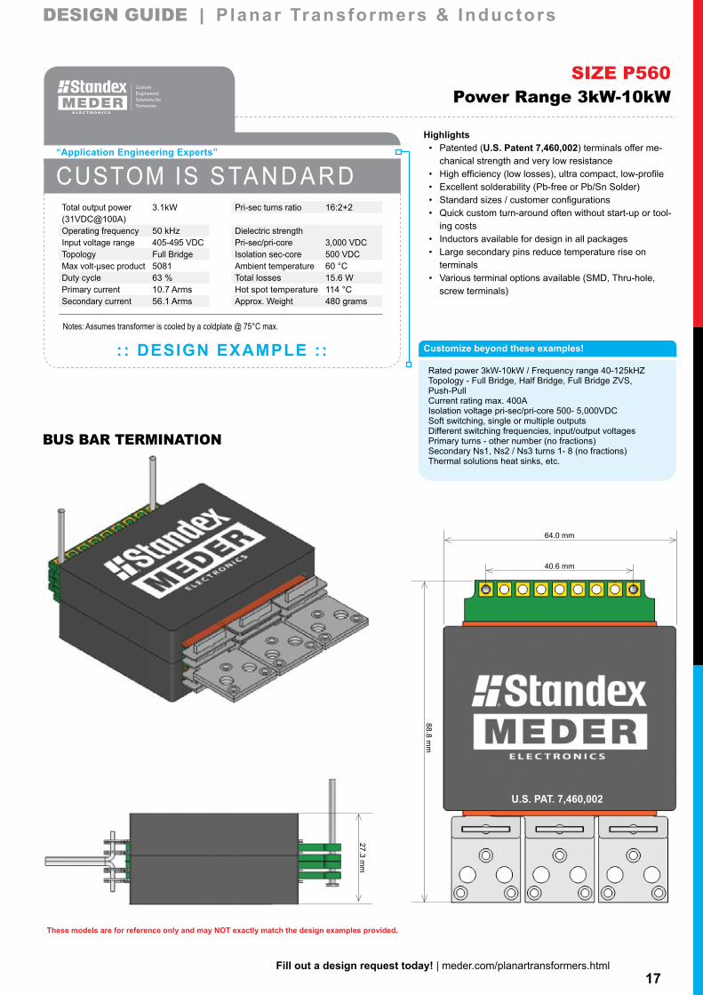
Rated power 3kW-10kW / Frequency range 40-125kHZTopology - Full Bridge, Half Bridge, Full Bridge ZVS,Push-PullCurrent rating max. 400AIsolation voltage pri-sec/pri-core 500- 5,000VDCSoft switching, single or multiple outputsDifferent switching frequencies, input/output voltagesPrimary turns - other number (no fractions)Secondary Ns1, Ns2 / Ns3 turns 1- 8 (no fractions)Thermal solutions heat sinks, etc.
Highlights• Patented (U.S. Patent 7,460,002) terminals offer me-
chanical strength and very low resistance• High efficiency (low losses), ultra compact, low-profile• Excellent solderability (Pb-free or Pb/Sn Solder)• Standard sizes / customer configurations• Quick custom turn-around often without start-up or tool-
ing costs• Inductors available for design in all packages• Large secondary pins reduce temperature rise on
terminals• Various terminal options available (SMD, Thru-hole,
screw terminals)
SIZE P560Power Range 3kW-10kW
CUSTOM IS S TA N D A R D
: : DESIGN EXAMPLE ::
“Application Engineering Experts”
Pri-sec turns ratio 16:2+2
Dielectric strengthPri-sec/pri-core 3,000 VDCIsolation sec-core 500 VDCAmbient temperature 60 °CTotal losses 15.6 WHot spot temperature 114 °CApprox. Weight 480 grams
Total output power 3.1kW(31VDC@100A)Operating frequency 50 kHzInput voltage range 405-495 VDCTopology Full BridgeMax volt-µsec product 5081Duty cycle 63 %Primary current 10.7 ArmsSecondary current 56.1 Arms
Notes: Assumes transformer is cooled by a coldplate @ 75°C max.
18Fill out a design request today! | meder.com/planartransformers.html
These models are for reference only and may NOT exactly match the design examples provided.
33.8 mm
72.8 mm
74.9 mm
64.0 mm
40.6 mm
U.S. PAT. 7,460,002
DESIGN GUIDE | Planar Transformers & InductorsDESIGN GUIDE | Planar Transformers & Inductors
BUS BAR TERMINATION
Customize beyond these examples!
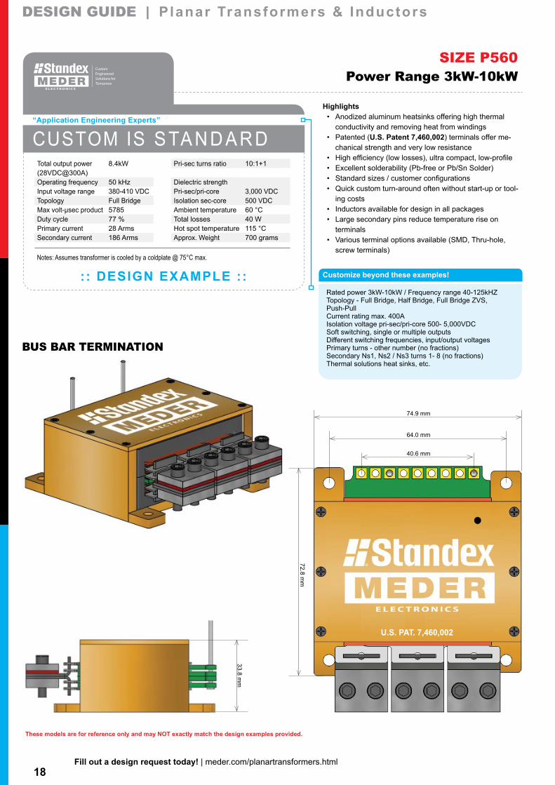
Rated power 3kW-10kW / Frequency range 40-125kHZTopology - Full Bridge, Half Bridge, Full Bridge ZVS,Push-PullCurrent rating max. 400AIsolation voltage pri-sec/pri-core 500- 5,000VDCSoft switching, single or multiple outputsDifferent switching frequencies, input/output voltagesPrimary turns - other number (no fractions)Secondary Ns1, Ns2 / Ns3 turns 1- 8 (no fractions)Thermal solutions heat sinks, etc.
Highlights• Anodized aluminum heatsinks offering high thermal
conductivity and removing heat from windings• Patented (U.S. Patent 7,460,002) terminals offer me-
chanical strength and very low resistance• High efficiency (low losses), ultra compact, low-profile• Excellent solderability (Pb-free or Pb/Sn Solder)• Standard sizes / customer configurations• Quick custom turn-around often without start-up or tool-
ing costs• Inductors available for design in all packages• Large secondary pins reduce temperature rise on
terminals• Various terminal options available (SMD, Thru-hole,
screw terminals)
SIZE P560Power Range 3kW-10kW
CUSTOM IS S TA N D A R D
: : DESIGN EXAMPLE ::
“Application Engineering Experts”
Pri-sec turns ratio 10:1+1
Dielectric strengthPri-sec/pri-core 3,000 VDCIsolation sec-core 500 VDCAmbient temperature 60 °CTotal losses 40 WHot spot temperature 115 °CApprox. Weight 700 grams
Total output power 8.4kW(28VDC@300A)Operating frequency 50 kHzInput voltage range 380-410 VDCTopology Full BridgeMax volt-µsec product 5785Duty cycle 77 %Primary current 28 ArmsSecondary current 186 Arms
Notes: Assumes transformer is cooled by a coldplate @ 75°C max.

19Fill out a design request today! | meder.com/planartransformers.html
These models are for reference only and may NOT exactly match the design examples provided.
35.6 mm
6.3 mm
110.6 mm
83.0 mm
63.4 mm
U.S. PAT. 7,460,002
DESIGN GUIDE | Planar Transformers & InductorsDESIGN GUIDE | Planar Transformers & Inductors
BUS BAR TERMINATION
Customize beyond these examples!
Rated power 10KW-20kW / Frequency range 40-125kHZ Topology - Full Bridge, Half Bridge, Full Bridge ZVS, Push-Pull Current rating max. 500A Isolation voltage pri-sec/pri-core 500- 5,000VDC Soft switching, single or multiple outputs Different switching frequencies, input/output voltages Primary turns - other number (no fractions) Secondary Ns1 turns 1- 4 (no fractions) Thermal solutions heat sinks, etc.
Highlights• Patented (U.S. Patent 7,460,002) terminals offer me-
chanical strength and very low resistance• High efficiency (low losses), ultra compact, low-profile• Excellent solderability (Pb-free or Pb/Sn Solder)• Standard sizes / customer configurations• Quick custom turn-around often without start-up or tool-
ing costs• Inductors available for design in all packages• Large secondary pins reduce temperature rise on
terminals• Various terminal options available (SMD, Thru-hole,
screw terminals)
SIZE P900Power Range 10kW-20kW
CUSTOM IS S TA N D A R D
: : DESIGN EXAMPLE ::
“Application Engineering Experts”
Pri-sec turns ratio 12:2+2
Dielectric strengthPri-sec/pri-core 4,000 VDCIsolation sec-core 1,000 VDCAmbient temperature 60 °CTotal losses 90 WHot spot temperature 105 °CApprox. Weight 550 grams
Total output power 10kW(40VDC@250A)Operating frequency 30 kHzInput voltage range 252-308 VDCTopology Full Bridge ZVSMax volt-µsec product 8236Duty cycle 98 %Primary current 46 ArmsSecondary current 177 Arms
Notes: Assumes transformer is cooled by a heatsink @ 75°C max. and forced airflow
20Fill out a design request today! | meder.com/planartransformers.html
These models are for reference only and may NOT exactly match the design examples provided.
56.5 mm
8.1 mm
125.1 mm
12.7 mm
50.8 mm
118.1 mm
108.0 mm
64.6 mm
U.S. PAT. 7,460,002
DESIGN GUIDE | Planar Transformers & InductorsDESIGN GUIDE | Planar Transformers & Inductors
BUS BAR TERMINATION
Customize beyond these examples!
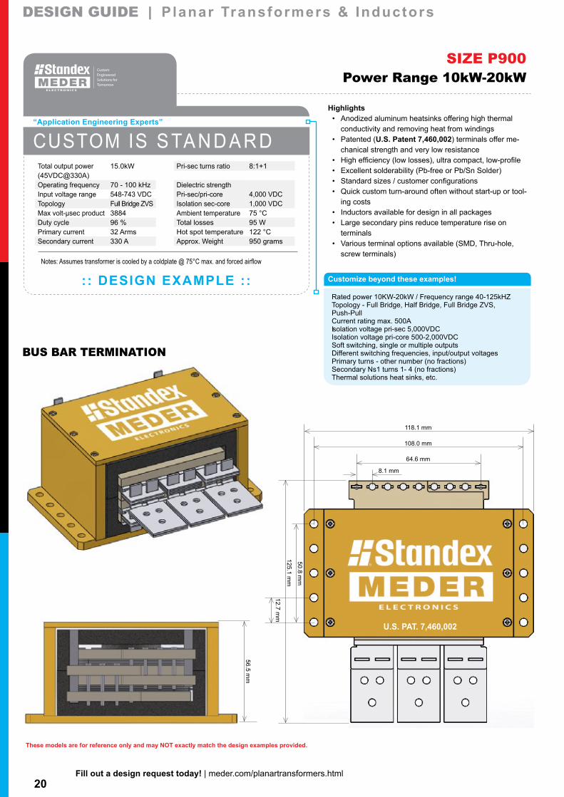
Rated power 10KW-20kW / Frequency range 40-125kHZ Topology - Full Bridge, Half Bridge, Full Bridge ZVS, Push-Pull Current rating max. 500A Isolation voltage pri-sec 5,000VDC Isolation voltage pri-core 500-2,000VDC Soft switching, single or multiple outputs Different switching frequencies, input/output voltages Primary turns - other number (no fractions) Secondary Ns1 turns 1- 4 (no fractions) Thermal solutions heat sinks, etc.
Highlights• Anodized aluminum heatsinks offering high thermal
conductivity and removing heat from windings• Patented (U.S. Patent 7,460,002) terminals offer me-
chanical strength and very low resistance• High efficiency (low losses), ultra compact, low-profile• Excellent solderability (Pb-free or Pb/Sn Solder)• Standard sizes / customer configurations• Quick custom turn-around often without start-up or tool-
ing costs• Inductors available for design in all packages• Large secondary pins reduce temperature rise on
terminals• Various terminal options available (SMD, Thru-hole,
screw terminals)
SIZE P900Power Range 10kW-20kW
CUSTOM IS S TA N D A R D
: : DESIGN EXAMPLE ::
“Application Engineering Experts”
Pri-sec turns ratio 8:1+1
Dielectric strengthPri-sec/pri-core 4,000 VDCIsolation sec-core 1,000 VDCAmbient temperature 75 °CTotal losses 95 WHot spot temperature 122 °CApprox. Weight 950 grams
Total output power 15.0kW(45VDC@330A)Operating frequency 70 - 100 kHzInput voltage range 548-743 VDCTopology Full Bridge ZVSMax volt-µsec product 3884Duty cycle 96 %Primary current 32 ArmsSecondary current 330 A
Notes: Assumes transformer is cooled by a coldplate @ 75°C max. and forced airflow
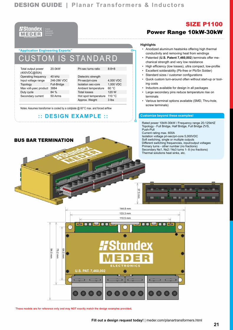
21Fill out a design request today! | meder.com/planartransformers.html
These models are for reference only and may NOT exactly match the design examples provided.
37.5 mm
133.3 mm
110.5 mm
94.0 mm
64.0 mm
75.2 mm
144.8 mm
U.S. PAT. 7,460,002
DESIGN GUIDE | Planar Transformers & InductorsDESIGN GUIDE | Planar Transformers & Inductors
BUS BAR TERMINATION
SIZE P1100Power Range 10kW-30kW
CUSTOM IS S TA N D A R D
: : DESIGN EXAMPLE ::
“Application Engineering Experts”
Pri-sec turns ratio 8:8+8
Dielectric strengthPri-sec/pri-core 4,000 VDCIsolation sec-core 1,000 VDCAmbient temperature 60 °CTotal losses 120 WHot spot temperature 110 °CApprox. Weight 3 lbs
Total output power 20.0kW(400VDC@50A)Operating frequency 40 kHzInput voltage range 246-286 VDCTopology Full-BridgeMax volt-µsec product 3884Duty cycle 84 %Secondary current 50 Arms
Customize beyond these examples!
Rated power 10kW-30kW / Frequency range 20-125kHZTopology - Full Bridge, Half Bridge, Full Bridge ZVS,Push-PullCurrent rating max. 600AIsolation voltage pri-sec/pri-core 5,000VDCSoft switching, single or multiple outputsDifferent switching frequencies, input/output voltagesPrimary turns - other number (no fractions)Secondary Ns1, Ns2 / Ns3 turns 1- 8 (no fractions)Thermal solutions heat sinks, etc.
Highlights• Anodized aluminum heatsinks offering high thermal
conductivity and removing heat from windings• Patented (U.S. Patent 7,460,002) terminals offer me-
chanical strength and very low resistance• High efficiency (low losses), ultra compact, low-profile• Excellent solderability (Pb-free or Pb/Sn Solder)• Standard sizes / customer configurations• Quick custom turn-around often without start-up or tool-
ing costs• Inductors available for design in all packages• Large secondary pins reduce temperature rise on
terminals• Various terminal options available (SMD, Thru-hole,
screw terminals)Notes: Assumes transformer is cooled by a coldplate @ 60°C max. and forced airflow
22Fill out a design request today! | meder.com/planarinductors.html
32.5
31.7
1.8-7
618
22.5
8.630.8-1.2
13-18
27.0
29.5
4.613.5
19
8.63
0.8-1.2
313
21.7
22.6
3.310.7
14
6.430.3
2.36-7
DESIGN GUIDE | Planar Transformers & InductorsDESIGN GUIDE | Planar Transformers & Inductors DESIGN GUIDE | Planar Transformers & InductorsDESIGN GUIDE | Planar Transformers & Inductors
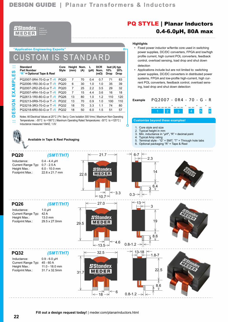
PQ32 (SMT/THT) Inductance: 0.9 - 6.0 µHCurrent Range Typ: 45 - 60 AHeight Max.: 11.0 - 18.0 mmFootprint Max.: 31.7 x 32.5mm
PQ26 (SMT/THT) Inductance: 1.0 µHCurrent Range Typ: 42 AHeight Max.: 13.0 mmFootprint Max.: 29.5 x 27.0mm
PQ20 (SMT/THT) Inductance: 0.4 - 4.4 µHCurrent Range Typ: 0.7 - 2.5 AHeight Max.: 6.0 - 10.0 mmFootprint Max.: 22.6 x 21.7 mm
Available in Tape & Reel Packaging
Highlights• Fixed power inductor w/ferrite core used in switching
power supplies, DC/DC converters, FPGA and low/high profile current, high current POL converters, feedback control, overload sensing, load drop and shut down
detection• Applications include but are not limited to: switching
power supplies, DC/DC converters in distributed power systems, FPGA and low-profile high-current, high cur-rent POL converters, feedback control, overload sens-ing, load drop and shut down detection
Example
PQ STYLE | Planar Inductors0.4-6.0µH, 80A max
Customize beyond these examples!
1. Core style and size2. Typical height in mm3. Min. inductance in “µH”, “R” = decimal point4. Typical Amp rating5. Terminal style - “G” = SMT, “T” = Through hole tabs6. Optional packaging “R” = Tape & Reel
P Q 2 0 0 7 - 0 R 4 - 7 0 - G - R_ _ _ _ _ _ - _ _ _ - _ _ - _ - _
1 2 3 4 5 6
:: D
ES
IGN
EX
AM
PLE
S :
: Standard Core Height Nom. L DCR Isat (A) typPart Number Style (mm) (A) (µH) Nom. 10% 20%“R” = Optional Tape & Reel (mΩ) Drop Drop
PQ2007-0R4-70-G or T -R PQ20 7 70 0.4 0.7 71 83PQ2006-1R0-30-G or T -R PQ20 6 30 1.0 1.0 35 39PQ2007-2R2-25-G or T -R PQ20 7 25 2.2 3.5 29 32PQ2007-4R4-15-G or T -R PQ20 7 15 4.4 3.6 16 18PQ2613-1R0-80-G or T -R PQ26 13 80 1.0 1.2 110 120PQ3213-0R9-70-G or T -R PQ32 13 70 0.9 1.0 100 110PQ3218-3R3-70-G or T -R PQ32 18 70 3.3 1.1 74 80PQ3218-6R0-50-G or T -R PQ32 18 50 6.0 1.5 51 57
Notes: All Electrical Values at 25°C | Pri: Sec’y: Core Isolation 300 Vrms | Maximum Non-Operating Temperatures : -55°C to +180°C | Maximum Operating Rated Temperatures: -30°C to +125°C | Inductance measured 10kHZ, 1.0V
CUSTOM IS S TA N D A R D
“Application Engineering Experts”
23Fill out a design request today! | meder.com/planartransformers.html
DESIGN GUIDE | Planar Transformers & InductorsDESIGN GUIDE | Planar Transformers & Inductors DESIGN GUIDE | Planar Transformers & InductorsDESIGN GUIDE | Planar Transformers & Inductors
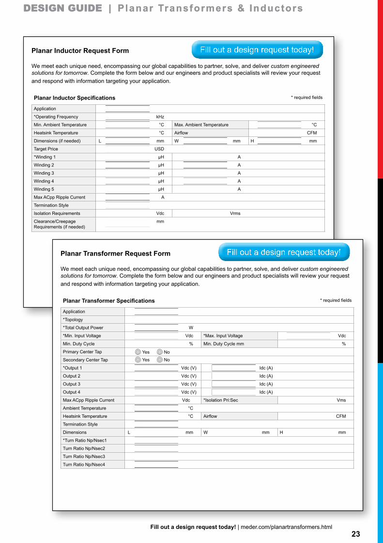
Planar Inductor Request Form
We meet each unique need, encompassing our global capabilities to partner, solve, and deliver custom engineered solutions for tomorrow. Complete the form below and our engineers and product specialists will review your request and respond with information targeting your application.
Planar Inductor Specifications * required fields
Application
*Operating Frequency kHz
Min. Ambient Temperature °C Max. Ambient Temperature °C
Heatsink Temperature °C Airflow CFM
Dimensions (if needed) mm mm mm
Target Price USD
*Winding 1 µH A
Winding 2 µH A
Winding 3 µH A
Winding 4 µH A
Winding 5 µH A
Max ACpp Ripple Current A
Termination Style
Isolation Requirements Vdc Vrms
Clearance/Creepage Requirements (if needed)
mm
L W H
Fill out a design request today!
Planar Transformer Request Form
We meet each unique need, encompassing our global capabilities to partner, solve, and deliver custom engineered solutions for tomorrow. Complete the form below and our engineers and product specialists will review your request and respond with information targeting your application.
Planar Transformer Specifications * required fields
Application
*Topology
*Total Output Power W
*Min. Input Voltage Vdc *Max. Input Voltage Vdc
Min. Duty Cycle % Min. Duty Cycle mm %
Primary Center Tap
Secondary Center Tap
*Output 1 Vdc (V) Idc (A)
Output 2 Vdc (V) Idc (A)
Output 3 Vdc (V) Idc (A)
Output 4 Vdc (V) Idc (A)
Max ACpp Ripple Current Vdc *Isolation Pri:Sec Vms
Ambient Temperature °C
Heatsink Temperature °C Airflow CFM
Termination Style
Dimensions mm mm mm
*Turn Ratio Np/Nsec1
Turn Ratio Np/Nsec2
Turn Ratio Np/Nsec3
Turn Ratio Np/Nsec4
L W H
Yes No
Yes No
Fill out a design request today!
24Fill out a design request today! | meder.com/planartransformers.html
Copyright ©Standex-Meder Electronics
Standex-Meder Electronics dynamic capabilities allows us to strategically partner with customers, solve problems, and deliver reliable high-quality custom or standard solutions to a wide array of markets. Our diverse product families of reed based, magnetics, and fluid level sensing components can play a role in numerous applications such as appliances, security, lighting, HVAC, plumbing, electronics, and more. Give us a [email protected]
Standex-Meder Electronics Smart City
SecuritySecurity CamerasDoor SensorsWindow SensorsSecurity GatesControl PanelsSmoke DetectorsCO2 DetectorsSprinkler SystemsOutside Lighting
HVAC and PlumbingCooling TowersSolar PanelsFurnacesAC CompressorsAC CondensersDehumidifiersHumidifiersGas Smart MetersElectric Smart MetersInstant Water HeatersStandard Water HeatersWater MetersFlush ValvesSprinkler Controllers
TransportationWasher Level SensorCoolant Level SensorKeyless EntryIgnition ImmobilizerAnti Lock BrakesDashboard LightingIgnition AssembliesHood Latch Verification
Offices & Break RoomsKeyboardsInkjet printersDesk lampsFlashlightsCable / BroadbandTime clocksTelephone SystemsCell phonesThermostatsDishwasherMicrowaveCoffeemakerRefridgeraterIce Maker
OtherFire ExtinguisersBattery ChargerProcess ControlPlastic Molding MachinesPower DistributionTransformersCircuit breakersMilling MachinesIndustrial DoorsArc WeldersHydraulicsFork Lift TrucksGrease Traps
DESIGN GUIDE | Planar Transformers & InductorsDESIGN GUIDE | Planar Transformers & Inductors
Designer Lighting
Automatic Shades
Tablet Keyboards
Sound Sensors for Toys
Guitar Amplifiers
Microphones
Organs
Fitness Equipment
Garage Door Openers
Speakers
Other
Dishwasher
Range
Oven
Microwave
Coffeemaker
Refrigerator
Ice Maker
Washers & Dryers
Appliances
Furnaces
Air Conditioning Compressors
Air Conditioning Condensers
Dehumidifiers
Humidifiers
Solar Panels
Gas Smart Meters
Electric Smart Meters
Instant Water Heaters
Standard Water Heaters
Water Meters
Shower Pumps
Pool and Spa Pumps
Sprinkler System Controllers
HVAC and Plumbing
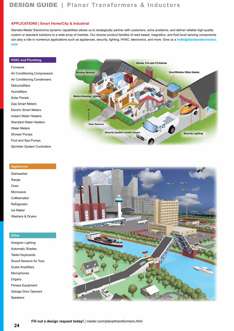
APPLICATIONS | Smart Home/City & Industrial
Standex-Meder Electronics dynamic capabilities allows us to strategically partner with customers, solve problems, and deliver reliable high-quality custom or standard solutions to a wide array of markets. Our diverse product families of reed based, magnetics, and fluid level sensing components can play a role in numerous applications such as appliances, security, lighting, HVAC, electronics, and more. Give us a [email protected]
25Fill out a design request today! | meder.com/planartransformers.html
Copyright ©Standex-Meder Electronics
Standex-Meder Electronics dynamic capabilities allows us to strategically partner with customers, solve problems, and deliver reliable high-quality custom or standard solutions to a wide array of markets. Our diverse product families of reed based, magnetics, and fluid level sensing components can play a role in numerous applications such as appliances, security, lighting, HVAC, plumbing, electronics, and more. Give us a [email protected]
Industrial Applications
SecuritySecurity CamerasDoor SensorsWindow SensorsSecurity GatesControl PanelsSmoke DetectorsCO2 DetectorsSprinkler SystemsOutside Lighting
HVAC and PlumbingCooling TowersSolar PanelsFurnacesAC CompressorsAC CondensersDehumidifiersHumidifiersGas Smart MetersElectric Smart MetersInstant Water HeatersStandard Water HeatersWater MetersFlush ValvesSprinkler Controllers
TransportationWasher Level SensorCoolant Level SensorKeyless EntryIgnition ImmobilizerAnti Lock BrakesDashboard LightingIgnition AssembliesHood Latch Verification
Offices & Break RoomsKeyboardsInkjet printersDesk lampsFlashlightsCable / BroadbandTime clocksTelephone SystemsCell phonesThermostatsDishwasherMicrowaveCoffeemakerRefridgeraterIce Maker
OtherFire ExtinguisersBattery ChargerProcess ControlPlastic Molding MachinesPower DistributionTransformersCircuit breakersMilling MachinesIndustrial DoorsArc WeldersHydraulicsFork Lift TrucksGrease Traps
Copyright ©Standex-Meder Electronics
Standex-Meder Electronics dynamic capabilities and solutions provide reed switches, relays, and sensors, magnetics, and fluid level sensing products throughout the transportation industry. Think of anything that turns on/off, opens/closes, requires power transfer, lighting, starting, measuring, or detecting – and we can play a role within that application. From read outs on the dashboard to measurement of coolant, brake, windshield, water in fuel, tire pressure, and emissions – our components perform within vital processes within automobiles, heavy-duty trucks, recreational vehicles, airplanes, trains, motorcycles, eCars, eBikes, boats, and more.Give us a [email protected]
Automotive Market Applications & Transportation Industry
Hood Latch Verification
Trailer Hitch Detection and Lights
Headlights and TaillightsBrake Fluid Sensor
Tire Pressure Monitoring
Anti-Theft Alarms
Ignition Immobilizer
Anti Lock Brakes
Interior and Dashboard Lighting / LED
Washer Level Sensor
Windshield Wiper Operation
Remote Door Locks and Keyless Entry
Coolant Level Sensor
Crash Safety Sensing Sunroofs
Gas Cap Detection
Fuel Level Sensors
Antennas
Engine Transformers, Coils and
Ignition Assemblies
Door Latch Sensors
Gear Shift
Music Video Systems
Seat Belt Detection
Brake Pedal
Battery Deactivation
Exhaust Fumes Detection
HVAC Controls
Mirror Controls
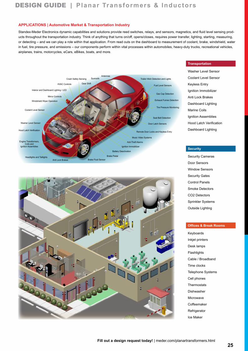
AUTOMOTIVE • HEAVY-DUTY TRUCKS • AVIATION • MARINE • RECREATIONAL VEHICLES • TRAINS • eCARS • eBIKES • MOTORCYCLES • MIL/AERO
DESIGN GUIDE | Planar Transformers & InductorsDESIGN GUIDE | Planar Transformers & Inductors
Keyboards
Inkjet printers
Desk lamps
Flashlights
Cable / Broadband
Time clocks
Telephone Systems
Cell phones
Thermostats
Dishwasher
Microwave
Coffeemaker
Refrigerator
Ice Maker
Offices & Break Rooms
Security Cameras
Door Sensors
Window Sensors
Security Gates
Control Panels
Smoke Detectors
CO2 Detectors
Sprinkler Systems
Outside Lighting
Security
Washer Level Sensor
Coolant Level Sensor
Keyless Entry
Ignition Immobilizer
Anti Lock Brakes
Dashboard Lighting
Marine Coils
Ignition Assemblies
Hood Latch Verification
Dashboard Lighting
Transportation
APPLICATIONS | Automotive Market & Transportation Industry
Standex-Meder Electronics dynamic capabilities and solutions provide reed switches, relays, and sensors, magnetics, and fluid level sensing prod-ucts throughout the transportation industry. Think of anything that turns on/off, opens/closes, requires power transfer, lighting, starting, measuring, or detecting – and we can play a role within that application. From read outs on the dashboard to measurement of coolant, brake, windshield, water in fuel, tire pressure, and emissions – our components perform within vital processes within automobiles, heavy-duty trucks, recreational vehicles, airplanes, trains, motorcycles, eCars, eBikes, boats, and more.
PARTNER | SOLVE | DELIVER™
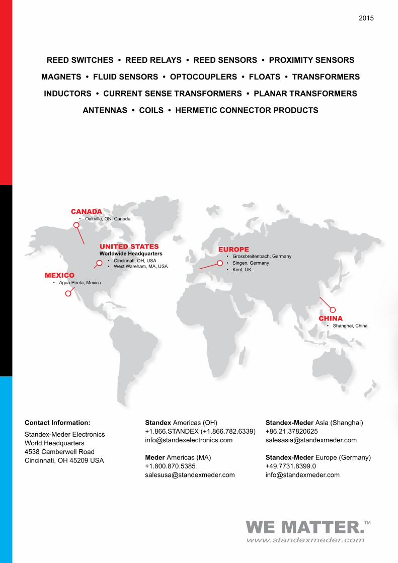
• Cincinnati, OH, USA• West Wareham, MA, USA
UNITED STATESWorldwide Headquarters
MEXICO• Agua Prieta, Mexico
• Grossbreitenbach, Germany• Singen, Germany• Kent, UK
EUROPE
CHINA• Shanghai, China
CANADA• Oakville, ON, Canada
2015
Contact Information:
Standex-Meder Electronics World Headquarters4538 Camberwell RoadCincinnati, OH 45209 USA
Standex Americas (OH)+1.866.STANDEX (+1.866.782.6339)[email protected]
Meder Americas (MA)[email protected]
Standex-Meder Asia (Shanghai)[email protected]
Standex-Meder Europe (Germany)[email protected]
REED SWITCHES • REED RELAYS • REED SENSORS • PROXIMITY SENSORS
MAGNETS • FLUID SENSORS • OPTOCOUPLERS • FLOATS • TRANSFORMERS
INDUCTORS • CURRENT SENSE TRANSFORMERS • PLANAR TRANSFORMERS
ANTENNAS • COILS • HERMETIC CONNECTOR PRODUCTS