MACH 4-PMDX SHOPBOT RETROFIT...
17
MACH 4-PMDX SHOPBOT RETROFIT GUIDE UVA Mechatronics Andy Cohen [email protected] Purpose This document provides a technical reference for the retrofitted ShopBot PRSAlpha as well as a guide to replicating the project on other ShopBot machines. Updated Sept. 20, 2015
Transcript of MACH 4-PMDX SHOPBOT RETROFIT...

0
MACH 4-PMDX SHOPBOT
RETROFIT GUIDE UVA Mechatronics
Andy Cohen [email protected]
Purpose This document provides a technical reference for the retrofitted ShopBot PRSAlpha as well as a
guide to replicating the project on other ShopBot machines. Updated Sept. 20, 2015

1
Table of Contents…………………………………………………………………………………..1 1 Introduction .......................................................................................................................................... 2
1.1 Purpose of the retrofit .................................................................................................................. 2
1.2 About the author .......................................................................................................................... 2
1.3 A guide to the guide ...................................................................................................................... 3
2 Software/Firmware installation ............................................................................................................ 3
3 Powering the SmartBOB ....................................................................................................................... 3
4 Wiring the Stepper Drivers ................................................................................................................... 4
4.1 Existing circuitry ............................................................................................................................ 4
4.1.1 Stepper driver input .............................................................................................................. 4
4.1.2 Stepper driver output ........................................................................................................... 5
4.2 Resoldering the stepper connections ........................................................................................... 5
4.2.1 Soldering the connector terminals ....................................................................................... 5
4.2.2 Additional soldering .............................................................................................................. 6
4.3 Wiring the driver inputs to the PMDX .......................................................................................... 6
5 Configuring Mach 4 for Motor Movement ........................................................................................... 7
5.1 Axis mapping ................................................................................................................................. 7
5.2 Motor configuration...................................................................................................................... 7
5.3 Homing .......................................................................................................................................... 8
6 Wiring the PMDX-407 and VFD ............................................................................................................. 8
6.1 Connecting to the SmartBOB ........................................................................................................ 8
6.2 Accessing the VFD ......................................................................................................................... 8
6.3 Wiring the VFD to the PMDX ........................................................................................................ 9
6.3.1 Existing circuitry .................................................................................................................... 9
6.3.2 Reconnecting the VFD ......................................................................................................... 10
6.4 Wiring reorganization ................................................................................................................. 11
7 Configuring Mach to Use the Spindle ................................................................................................. 12
8 Rewiring the Limit Switches ................................................................................................................ 12
8.1 Existing circuitry .......................................................................................................................... 12
8.2 Rewiring the limit switches ......................................................................................................... 13
9 Configuring Mach to Use Limit Switches ............................................................................................ 14
10 Implementing the Homing Script .................................................................................................... 14
11 Future Work .................................................................................................................................... 14

2
11.1 Backlash compensation .............................................................................................................. 14
11.2 Rewiring the contactors .............................................................................................................. 15
11.3 Replacing the contactors ............................................................................................................ 15
11.4 E-stop wiring ............................................................................................................................... 15
11.5 Wiring aesthetics ........................................................................................................................ 15
11.6 Profile shortcut ........................................................................................................................... 15
11.7 Alarm Clear output ...................................................................................................................... 15
11.8 Keyboard/pendant jogging ......................................................................................................... 16
11.9 Custom screens ........................................................................................................................... 16
1 Introduction
1.1 Purpose of the retrofit The ShopBot PRSAlpha is an entry-level CNC machine capable of cutting workpieces approximately 4’x8’.
The machine is well-built mechanically and extremely cost-effective when compared against more
traditional CNC machines. However, because it is entry-level, its target customers tend to be unfamiliar
with CNC. Therefore, the software and interfaces have been significantly simplified.
For more experienced users who wish to gain greater control and further optimize their machines, this
presents significant problems. Chief among them are a poor user interface, a failure to show the
toolpath or G-code behind the cut, a lack of real-time adjustment of parameters such as feed rate and
spindle speed, and an inability to recognize or manually input G-code commands.
The aim of this retrofit was therefore to address these issues by upgrading the machine to work with a
better interface. Mach 4 was chosen as the most suitable interface, and utilized the PMDX-422
SmartBOB as the system’s motion controller in conjunction with an external PMDX-407 spindle
controller.
1.2 About the author The author, Andy Cohen, is a mechanical engineering student at Virginia Tech. He undertook this project
during the summer of 2015 under the supervision of UVA Professor Gavin Garner, and wrote the guide
after its conclusion. To contact the author with questions or comments about this guide or the project in
general, please use the email address posted on the title page of the document.

3
1.3 A guide to the guide This guide has two main purposes: First, to serve as a sort of technical manual for the updated circuitry,
Mach 4 configuration, and other modifications made to the ShopBot system as part of the retrofit. The
guide will focus mostly on the features unique to this particular configuration, and may exclude some
information already detailed in existing documentation of components of the system such as the
stepper drivers and variable frequency drive (VFD). These documents are posted below:
Yaskawa V1000 VFD technical manual:
https://www.yaskawa.com/pycprd/lookup/getdocument/jvgyvE5ZTUY_5CC1znzBobLdnyGOw4CptIV
Fb4EEduTxhP4O_LXClunkmo2u3S1rL898u7-4hXnd2DN_2D-hJq-EnjN1Ak_RP280b9mnraA
Alpha Step stepper drivers technical manual:
http://orientalmotor.com/products/pdfs/opmanuals/HM-6159-18E.pdf
Operations manual for completed system with documented issues and troubleshooting:
Posted on acohen8.weebly.com under Projects -> ShopBot CNC Retrofit
The secondary purpose of this guide is to provide an instruction manual for those wishing to upgrade
their own ShopBot systems to Mach 4 and detail the author’s process. The guide will describe the
retrofit process in a way that should provide ample guidance to those who wish to replicate his results.
2 Software/Firmware installation Mach4Hobby can be downloaded and trialed without a license, so before the system is completely ready
to run G-code it is recommended to do so. The latest version of Mach 4 can be found here:
http://www.pmdx.com/Downloads_Mach4/Mach4_Hobby_Releases/
After installing Mach 4, install the PMDX plugin and update the board’s firmware via the steps described
in the PMDX Quick Start guide:
http://www.pmdx.com/Doc/PMDX-422_Quick_Start_Rev0_3.pdf
3 Powering the SmartBOB WARNING: Before performing any of the steps detailed in this guide, place a piece of cardboard, plastic,
or other nonconductive material within the control box where you intend to place the SmartBOB. The
metal casing of the control box is grounded, and may short the board if a pin comes into contact with
the board’s underside.
The board will run off of power provided by the USB connection, but that is not a good permanent
option. Instead, provide the board with a five volt input from the existing +5V power supply within the
ShopBot control box, and wire the ground terminal of the board to the box’s row of ground screw
terminals.

4
4 Wiring the Stepper Drivers
4.1 Existing circuitry
4.1.1 Stepper driver input The stepper drivers take their inputs through the CN4 connection located in the lower right of the
drivers’ faces. The connectors, created by 3M, have 36 pins. Not all are utilized in the ShopBot system,
however. Figure 4.1 shows a connector with its protective casing removed, and Figures 4.2 and 4.3
indicate the pins utilized.
Figure 4.2 A table of the pin connections on CN4, from page 34 of Alpha Step manual
Figure 4.1 A disassembled connector
Figure 4.3 The pin connections, diagrammed and labeled. Pen color corresponds to wire color. A dot indicates another wire of the dot’s color meets the text color wire at the pin.

5
4.1.2 Stepper driver output The signals are passed to the stepper drivers via a set of labeled pins on the ShopBot’s proprietary
breakout board. Their correspondence to the wire colors and actual signals is indicated in Figure 4.4.
4.2 Resoldering the stepper
connections
4.2.1 Soldering the connector terminals Much of the above circuitry is redundant and/or unnecessary for operation of the ShopBot. Therefore it is advisable to simply rewire the stepper drivers rather than utilize the existing ribbon connectors. The connectors can be ordered here: http://www.newark.com/3m/10136-3000pe/mini-d-ribbon-connector-
plug-36/dp/69K7226, and their casings can be ordered here: http://www.newark.com/3m/10336-52f0-008/junction-shell-glass-filled-polyester/dp/90B8573.
A diagram is shown below of the resoldered connectors. Compared to the ShopBot’s wiring schematic, it is much easier to understand and wire into the PMDX. The longer and shorter sides have been indicated for clarity, as the existing documentation does not make the connector’s orientation clear. It is helpful to use 28 AWG ribbon cable with 4 wires to organize each connector. To more easily solder the terminals, lightly tin the tips of the wires and then bend them into a hook shape to latch onto the terminals’ holes. This will keep them in place while soldering. Be sure to use heat shrink to prevent shorts.
Figure 4.7 Schematic of the redesigned connector
Figure 4.5 The driver output pins on the breakout
Figure 4.4 The female pin headers connecting to the breakout board. With reference to Figure 4.5, the ribbon cable would come off to the right when plugged in, and the GND pins would be topmost to match the male pins. Circled connections are wired together at the stepper driver pins.
Figure 4.6 A finished connector
6
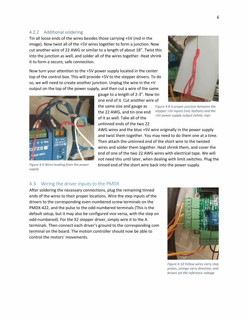
4.2.2 Additional soldering Tin all loose ends of the wires besides those carrying +5V (red in the
image). Now twist all of the +5V wires together to form a junction. Now
cut another wire of 22 AWG or similar to a length of about 18”. Twist this
into the junction as well, and solder all of the wires together. Heat shrink
it to form a secure, safe connection.
Now turn your attention to the +5V power supply located in the center
top of the control box. This will provide +5V to the stepper drivers. To do
so, we will need to create another junction. Unplug the wire in the +V
output on the top of the power supply, and then cut a wire of the same
gauge to a length of 2-3”. Now tin
one end of it. Cut another wire of
the same size and gauge as
the 22 AWG, and tin one end
of it as well. Take all of the
untinned ends of the two 22
AWG wires and the blue +5V wire originally in the power supply
and twist them together. You may need to do them one at a time.
Then attach the untinned end of the short wire to the twisted
wires and solder them together. Heat shrink them, and cover the
end of one of the two 22 AWG wires with electrical tape. We will
not need this until later, when dealing with limit switches. Plug the
tinned end of the short wire back into the power supply.
4.3 Wiring the driver inputs to the PMDX After soldering the necessary connections, plug the remaining tinned
ends of the wires to their proper locations. Wire the step inputs of the
drivers to the corresponding even-numbered screw terminals on the
PMDX-422, and the pulse to the odd-numbered terminals (This is the
default setup, but it may also be configured vice versa, with the step on
odd-numbered). For the X2 stepper driver, simply wire it to the A
terminals. Then connect each driver’s ground to the corresponding com
terminal on the board. The motion controller should now be able to
control the motors’ movements.
Figure 4.8 A proper junction between the stepper +5V inputs (red, bottom) and the +5V power supply output (white, top)
Figure 4.9 Wires leading from the power supply
Figure 4.10 Yellow wires carry step pulses, orange carry direction, and brown set the reference voltage
7
5 Configuring Mach 4 for Motor Movement
5.1 Axis mapping Launch the Mach 4 GUI. Upon opening it, duplicate the
PMDX-Sample profile, and rename it something such as
“Shopbot_PMDX”. Open this profile and then navigate to
Configure -> Mach. This will open the configuration window.
Once it is open, navigate to the Axis Mapping tab. Map the
motors as shown at right. Motor3 corresponds to the X2
motor, and by slaving it we ensure the same signal is sent to
both X-motors and prevent canting of the gantry.
5.2 Motor configuration The motors must now be individually configured. Navigate to the Motors tab, then click on Motor0. Set
the Counts Per Unit value to 496.8, velocity to 1000 units/minute, and acceleration to 30 units/s2 . The
latter two are currently just rough estimates of reasonable values, but the accuracy of the Counts Per
Unit value is very important; this determines how many pulses the PMDX will output in order to create
an inch of movement, and thus determines what position Mach 4 thinks it has reached.
The value was carefully determined by creating a thin mark on the aluminum structure at the current
location, jogging the machine 10 inches in the relevant direction, and then similarly marking the new
position. This was then measured using large calipers, and the value would be adjusted for the next test
run until the desired accuracy was attained. It is recommended that users check this value in the same
manner on their own machines, and adjust as needed for each axis.
Once this data has been input, reverse the direction of Motor0. Ignore the Backlash and Enable Delay for
now-while backlash is an issue, at present the PMDX does not support PMDX compensation. See “Future
Work” or the Operations Guide’s “Known Issues” section for more information.
Do the same for Motor3. If it is enabled and not set up in the exact same manner as its master, Motor0,
then Mach4 will throw an error and refuse to enable the SmartBOB. Now set up the y-motor, Motor1, in
the exact same manner as well. Motor2, the z-motor, should be set up as shown below:
Figure 5.1 Proper axis mapping
Figure 5.2 The z-motor configuration 597.17 counts per unit 250 units/minute 40 units/sec^2
8
5.3 Homing Navigate to the Homing/SoftLimits tab in the configuration window. This machine does not use homing
switches, so the user should simply check “Home in Place” for the X, Y, and Z axes. This will allow the
machine to reference its axes.
6 Wiring the PMDX-407 and VFD
6.1 Connecting to the SmartBOB Switch jumper 1, located on the PMDX-422 below the parallel port terminals, to the “on” position. This
allows the PMDX-422 to power external devices including the spindle control board (PMDX-407). Then,
simply align the strip of female headers on the underside of the 407 with the male headers of the 422
and push them together. If you have trouble fitting them together, check that the small notch in the
walls surrounding the SmartBOB’s male headers aligns with the capacitor on the underside of the 407
and try again.
To allow the SmartBOB to control the VFD, you will also need to change one of the VFD’s parameters.
On the main screen, navigate using the up and down arrows until the parameter option appears. Select
it, and then navigate to the b1-01 parameter. Change this from the default state of 0 to 1. This changes
the input from digital (Modbus) to analog provided by the PMDX.
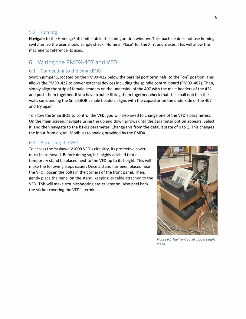
6.2 Accessing the VFD To access the Yaskawa V1000 VFD’s circuitry, its protective cover
must be removed. Before doing so, it is highly advised that a
temporary stand be placed next to the VFD up to its height. This will
make the following steps easier. Once a stand has been placed near
the VFD, loosen the bolts in the corners of the front panel. Then,
gently place the panel on the stand, keeping its cable attached to the
VFD. This will make troubleshooting easier later on. Also peel back
the sticker covering the VFD’s terminals.
Figure 6.1 The front panel atop a simple stand

9
6.3 Wiring the VFD to the PMDX
6.3.1 Existing circuitry The ShopBot normally sends spindle control signals via an RS 485 cable
connecting to the control computer’s USB port. It uses the Modbus
communication protocol, and the VFD’s Modbus input/output is
composed of the top five screw terminals on the VFD. Detach the wires
from each of these terminals. This not only disables communication, but
will also allow us to access the middle set of screw terminals.
Now examine the lower set of screw terminals. Diagrammed below is the
current connection of the VFD to the ShopBot’s breakout board:
Figure 6.3 Digital inputs of the VFD
Note the two wires from the breakout board, FWD and DCM. These
wires will be disconnected from the breakout board. To find them,
trace the brown cable from the cable port on the right of the
ShopBot control box to the pictured terminals on the breakout
board. Disconnect them, and place electrical tape over their ends to
prevent shorts. Do the same with the S1 terminal on the VFD. The SC
terminal should remain untouched for now.
Figure 6.2 Details of the inputs, from the Yaskawa V1000 manual
Figure 6.4 The VFD digital terminals on the lower left of the breakout board
10
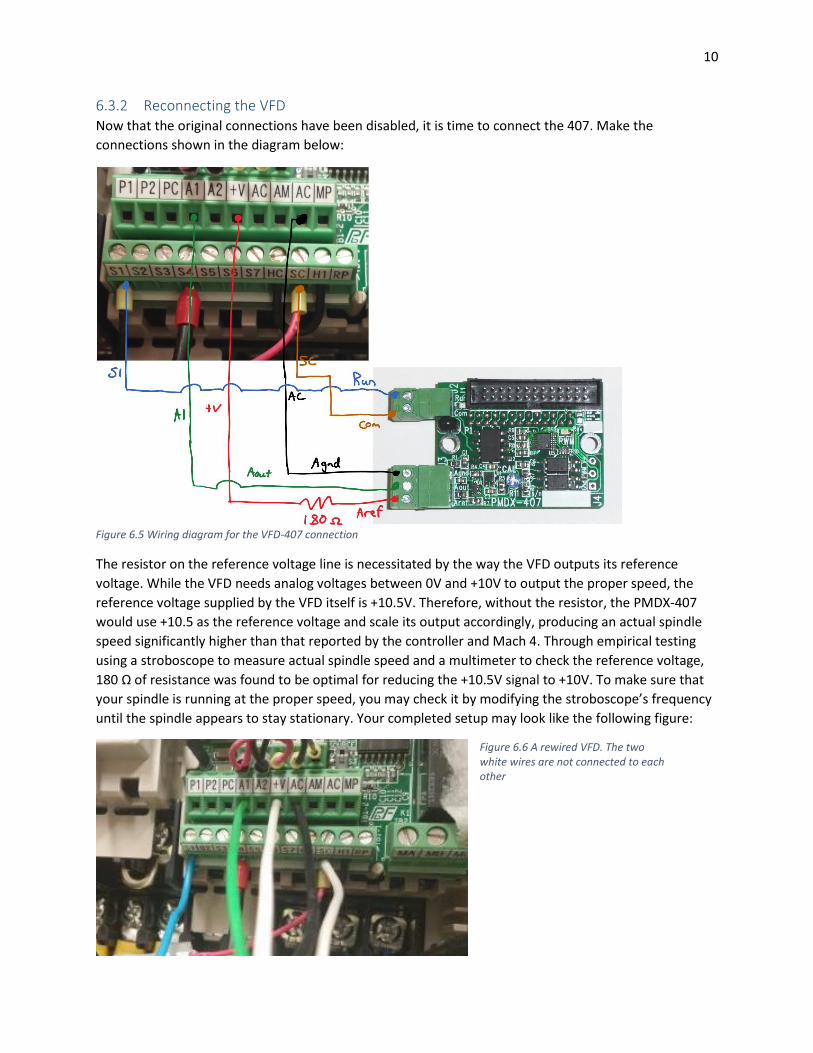
6.3.2 Reconnecting the VFD Now that the original connections have been disabled, it is time to connect the 407. Make the
connections shown in the diagram below:
Figure 6.5 Wiring diagram for the VFD-407 connection
The resistor on the reference voltage line is necessitated by the way the VFD outputs its reference
voltage. While the VFD needs analog voltages between 0V and +10V to output the proper speed, the
reference voltage supplied by the VFD itself is +10.5V. Therefore, without the resistor, the PMDX-407
would use +10.5 as the reference voltage and scale its output accordingly, producing an actual spindle
speed significantly higher than that reported by the controller and Mach 4. Through empirical testing
using a stroboscope to measure actual spindle speed and a multimeter to check the reference voltage,
180 Ω of resistance was found to be optimal for reducing the +10.5V signal to +10V. To make sure that
your spindle is running at the proper speed, you may check it by modifying the stroboscope’s frequency
until the spindle appears to stay stationary. Your completed setup may look like the following figure:
Figure 6.6 A rewired VFD. The two white wires are not connected to each other
11
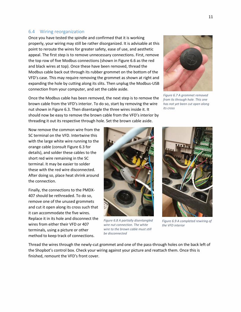
6.4 Wiring reorganization Once you have tested the spindle and confirmed that it is working
properly, your wiring may still be rather disorganized. It is advisable at this
point to reroute the wires for greater safety, ease of use, and aesthetic
appeal. The first step is to remove unnecessary connections. First, remove
the top row of five Modbus connections (shown in Figure 6.6 as the red
and black wires at top). Once these have been removed, thread the
Modbus cable back out through its rubber grommet on the bottom of the
VFD’s case. This may require removing the grommet as shown at right and
expanding the hole by cutting along its slits. Then unplug the Modbus-USB
connection from your computer, and set the cable aside.
Once the Modbus cable has been removed, the next step is to remove the
brown cable from the VFD’s interior. To do so, start by removing the wire
nut shown in Figure 6.3. Then disentangle the three wires inside it. It
should now be easy to remove the brown cable from the VFD’s interior by
threading it out its respective through hole. Set the brown cable aside.
Now remove the common wire from the
SC terminal on the VFD. Intertwine this
with the large white wire running to the
orange cable (consult Figure 6.3 for
details), and solder these cables to the
short red wire remaining in the SC
terminal. It may be easier to solder
these with the red wire disconnected.
After doing so, place heat shrink around
the connection.
Finally, the connections to the PMDX-
407 should be rethreaded. To do so,
remove one of the unused grommets
and cut it open along its cross such that
it can accommodate the five wires.
Replace it in its hole and disconnect the
wires from either their VFD or 407
terminals, using a picture or other
method to keep track of connections.
Thread the wires through the newly-cut grommet and one of the pass-through holes on the back left of
the Shopbot’s control box. Check your wiring against your picture and reattach them. Once this is
finished, remount the VFD’s front cover.
Figure 6.7 A grommet removed from its through hole. This one has not yet been cut open along its cross
Figure 6.8 A partially disentangled wire nut connection. The white wire to the brown cable must still be disconnected
Figure 6.9 A completed rewiring of the VFD interior
12
7 Configuring Mach to Use the Spindle First, the PMDX-407 must be set up to control the spindle speed. To do so, navigate to Configure ->
Plugins -> PMDX-Smartbob… -> Configure -> Feature Config. Then, under PWM Spindle Speed Control,
click PMDX-407 to enable it, and check “Report calculated…as actual spindle RPM.” Since the VFD does
not provide actual speed feedback, this must be enabled to view the spindle speed in Mach.
Navigate to Configure -> Mach4 -> Spindle. Set the minimum RPM to 2000, and the maximum to 18000.
The minimum value represents the lowest speed at which the spindle can turn, as specified by the
manufacturer. In this case, it is simply a rough estimate based on experience. The maximum, however, is
based on manufacturer specifications. Next, set the acceleration and deceleration times to 5 seconds
each. These too are rough approximations, but if not changed from the default value of 0, the spindle
will not reach its nominal speed.
8 Rewiring the Limit Switches
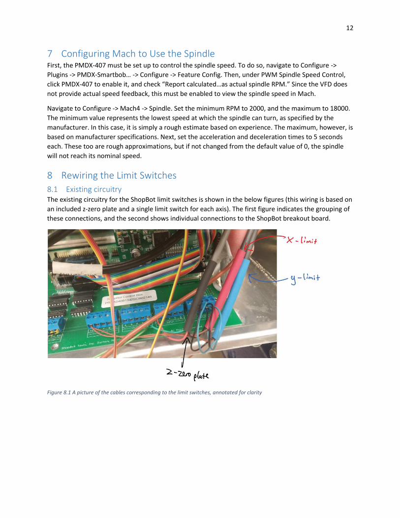
8.1 Existing circuitry The existing circuitry for the ShopBot limit switches is shown in the below figures (this wiring is based on
an included z-zero plate and a single limit switch for each axis). The first figure indicates the grouping of
these connections, and the second shows individual connections to the ShopBot breakout board.
Figure 8.1 A picture of the cables corresponding to the limit switches, annotated for clarity

13
Figure 8.2 A diagram of the electrical connections on the breakout board relating to the switches
After inspecting your machine’s wiring and comparing it with the above figures, disconnect all wires
from the ShopBot’s breakout board besides the light green wire running to the screw terminal strip.
8.2 Rewiring the limit switches
Figure 8.3 A wiring schematic for the limit switches. Colors correspond to the existing wires in the ShopBot's original configuration
Once the previous wiring has been disconnected, use the above schematic as a guide for rewiring the
switch connections. Avoid using input 10 for any of the limit switches as it is normally reserved for the
emergency stop. You may vary which inputs on the PMDX-407 you use, but 11, 12, and 13 have been
used for simplicity and sequential ordering. When earlier soldering a junction at the +5V power supply, a
single wire should have been left disconnected. Use this wire to power the z-zero plate.

14
9 Configuring Mach to Use Limit Switches Navigate to Configure -> Mach 4 -> Input Signals. Check the boxes shown below.
The Motor -- signals correspond to lower limit switch signals that, when activated, will prevent the
machine from overstepping its bounds and damaging itself. The user should not enable the Motor++,
however, since the ShopBot only has one inductive proximity sensor per axis (though the z has only a
hard mechanical stop). This means that Mach 4 cannot distinguish between a positive and negative limit,
and so in configuring Mach, a choice must be made on which signal will be read: positive or negative.
The decision of which to activate is based on the user’s situation-it is advisable to activate the signal the
user most often expects to encounter. This necessitates the use of a limit override when the less often
expected signal is triggered, which is documented in the accompanying operations manual, found under
“A guide to the guide.”
The digitize input corresponds to the z-zero plate and allows G31 commands to use this input. Note the
checkbox at right, which must be set to “Active Low,” since the z-zero plate outputs a high voltage when
not making contact.
10 Implementing the Homing Script To zero the machine’s z-axis to the surface of the part, a special homing script is needed. The script may
be downloaded from acohen8.weebly.com under Projects -> ShopBot CNC Retrofit. The script is
currently named “m11,” but if this conflicts with an existing script or macro, it may be changed to
another number. If this is done, however, the function’s name within the script must also be changed
correspondingly. Once the script is downloaded, place it into \Mach4Hobby\Profiles\Mach4Mill\Macros.
To call it, simply type “M11” in the MDI tab and run the script.
11 Future Work
11.1 Backlash compensation When cutting circular features, flat spots will sometimes appear at the positive and negative Y
quadrants of the circle. This is caused by backlash: The machine thinks it is switching direction and
moving, however because of about .016” of backlash in the y-motor assembly (measured with an
indicator dial) , it spins simply to take up that wiggle room, not moving in the y-direction and thus
producing a straight line at the quadrant.

15
While it is accounted for in Mach 4 in the motor configuration screen, according to Steve Stallings from
PMDX, “Backlash compensation must be implemented in the hardware device and its plugin.
The [PMDX] SmartBOB family does not yet support backlash compensation. Yes, it is on our list of things
to do. We are currently looking for the best way to do this.” –Posted July 29, 2015
When the backlash compensation is supported, this should be one of the first areas of future work.
11.2 Rewiring the contactors The current system still retains limited connections with the ShopBot breakout board, mostly to activate
the contactors responsible for distributing power to the rest of the system. In the future, these
connections will be replaced, and the process detailed in an updated version of this guide.
11.3 Replacing the contactors The contactors themselves have proven problematic at times. Because they are mechanical in nature,
with a large spring inside of them responsible for making and breaking the connection, they have the
potential to fail, as evidenced by two instances during the duration of the project. While not a
particularly complex fix was required-it just took a disassembly and jiggling of the internal mechanisms-
the fix caused a significant delay, as the contactors take some time to detach and subsequently reattach.
As such, it would be desirable in the future to entirely replace these with high-current solid state relays.
11.4 E-stop wiring The E-stop wiring is the last set of connections to the ShopBot breakout board besides that of the
aforementioned contactors. Due to time constraints and the continued functionality of the system
without it, this wiring was left untouched, though in order to completely remove the breakout board
and reduce system complexity, the E-stop should be rewired to function with only the PMDX motion
controller.
11.5 Wiring aesthetics While the control box may be closed, and the wires safe, there is still room for improvement. In the time
allotted for the project, the author did not have time to completely optimize the wiring. One
improvement in particular that should be made is enclosing the wires running to the PMDX-407 in mesh
tubing to protect the wires and improve cable management and aesthetics.
11.6 Profile shortcut For quick access to the specific profile necessary to run the ShopBot-PMDX mill, a profile shortcut can be
created in a process detailed in the Mach 4 configuration manual (See “A Guide to the Guide” for link).
11.7 Alarm Clear output When the stepper driver detects an abnormality in motor operation caused by such events as running
into a hard stop, it triggers an alarm output that signals to the motion controller that such an event has
occurred and stops motor operation. A red indicator light on the drivers is also activated to provide
visual confirmation (see stepper driver manual for further details). When the system was redesigned,
the wiring was simplified by excluding this output and the input that clears this alarm, as it was in the
vast majority of cases superfluous and necessitated additional complexity of setup. Currently the
system’s alarm must be cleared by simply cutting power to the drivers and then repowering them. This
is adequate for the system, but it would be preferable to enable the alarm clear signal to avoid restart.

16
11.8 Keyboard/pendant jogging The system currently requires the user to click on buttons with the mouse in order to jog the machine. It
would be advantageous, however, to enable not only keyboard jogging functionality, but also an
additional pendant that could be moved around the machine and direct its motions. This would involve
additional wiring and Mach 4 configuration, though, and is one of the latter planned updates.
11.9 Custom screens To optimize this machine’s operation, it would be desirable to create custom screens for the machine
that could, for instance, run the M11 auto-tool zero script via a button press or use larger buttons that
are more touch screen-friendly. Another future upgrade may involve a touch screen mounted near the
machine that would allow the user to more conveniently control the ShopBot.