MA Remote Controller Mitsubishi Electric PAR-21MAA ... · PDF file(ForOperation Mr. SLIM PUHZ...
76
<REVISED>
Transcript of MA Remote Controller Mitsubishi Electric PAR-21MAA ... · PDF file(ForOperation Mr. SLIM PUHZ...

New publication effective Mar 2005.Issued in Mar. 2005 M-P0254A SIZ<MEE>Printed in Japan
Revised publication, Aug 2008. <REVISED>


�
!.AdvantageofNewMARemoteController
@.NewFunctions
#.Appearance
$.EasyMaintenanceFunction(ForMr.SLIMPUHZseries)
%.How toSelectFunctionsofremotecontroller
^.Unit Function Setting by theRemoteController(forMr.SLIM)
&.TestRunbytheRemoteController(forMr.SLIM)
*.Self-DiagnosisbytheRemoteController(forMr.SLIM)
(.Monitoring the Operation Data bytheremoteController(forMr.SLIM)
).SystemControl(forMr.SLIM)
(
.ExternalDimensions
CONTENTS
!. AdvantageofNewMARemoteController...........................................................................2�. WeeklyTimer......................................................................................................................22. EasyMaintenanceFunction(OnlyforPUHZtype).............................................................23. NewDisplay........................................................................................................................3
3.� DotLiquidCrystalDisplay(LCD)........................................................................................................................ 33.2 Multi-languageDisplay....................................................................................................................................... 3
4. TheOtherFunctions...........................................................................................................34.� TemperatureRangeLimitSetting....................................................................................................................... 34.2 AutoOffTimer..................................................................................................................................................... 34.3 SimpleOperationLock....................................................................................................................................... 3
@. NewFunctions.......................................................................................................................4#. Appearance............................................................................................................................5
�. DisplaySection...................................................................................................................52. OperationSection...............................................................................................................5
$. EasyMaintenanceFunction(OnlyforMr.SLIMPUHZseries)..........................................6�. MaintenanceModeOperatingMethod................................................................................62. GuideforOperationCondition............................................................................................8
CheckPoints............................................................................................................................................................... 8
%. HowtoSelectFunctionsofremotecontroller....................................................................9�. FunctionItems....................................................................................................................92. FlowchartofFunctionSetting...........................................................................................�03. ScreenStructureforFunctionSetting............................................................................... ��4. FunctionSettingMode......................................................................................................�2
4.� ChangeLanguage............................................................................................................................................ �24.2 FunctionSetting................................................................................................................................................ �4
4.2.� OperationLock(OperationFunctionLimitSetting)............................................................................... �44.2.2 AutoModeSetting................................................................................................................................. �64.2.3 TemperatureRangeLimitSetting.......................................................................................................... �8
4.3 BasicFunctionsSetting.................................................................................................................................... 204.3.� RemoteControllerMain/SubSetting..................................................................................................... 204.3.2 Timerfunctionsetting(Weeklytimer/Autoofftimer/Simpletimer)........................................................ 2�4.3.3 ContactNumberSettingforErrorSituation........................................................................................... 33
4.4 DisplayChangeSetting.................................................................................................................................... 354.4.� TemperatureDisplay°C/°FSetting....................................................................................................... 354.4.2 RoomTemperatureDisplaySetting...................................................................................................... 364.4.3 AutomaticCooling/HeatingDisplaySetting.......................................................................................... 37
^. UnitFunctionSettingbytheRemoteController(forMr.SLIM)......................................38&. TestRunbytheRemoteController(forMr.SLIM)...........................................................42
�. CheckPointsUnderTestRun...........................................................................................422. TestRunusingtheWiredRemoteController....................................................................42
*. Self-DiagnosisbytheRemoteController(forMr.SLIM)..................................................44�.HowtoProceed“Self-diagnosis”.......................................................................................44
�.� WhenaProblemOccursDuringOperation...................................................................................................... 44�.2 Self-DiagnosisDuringMaintenanceorService................................................................................................ 44�.3 RemoteControllerDiagnosis............................................................................................................................ 45
2. ErrorCodeList..................................................................................................................46(. MonitoringtheOperationDatabytheremoteController(forMr.SLIM)........................48
�. Howto“MonitortheOperationData”................................................................................482. RequestCodeList............................................................................................................49
2.� DetailContentsinRequestCode..................................................................................................................... 53
). SystemControl(forMr.SLIM)............................................................................................58�. �-RemoteController(Standard)Operation.......................................................................60
�.� �WiredRemoteController............................................................................................................................... 60�.2 WirelessRemoteController.............................................................................................................................. 60
2. 2-RemoteControllerOperation.........................................................................................6�2.� 2WiredRemoteControllers............................................................................................................................. 6�2.2 2WirelessRemoteControllers......................................................................................................................... 6�2.3 �Wiredand�WirelessRemoteController...................................................................................................... 6�
3. GroupControlOperation(CollectiveOperationandControlofMultipleRefrigerantSystems(2to�6)).............................................................................................................62
4. Rotationfunction(andback-upfunction,2ndstagecut-infunction)................................634.� Operation.......................................................................................................................................................... 634.2 Howtosetrotationfunction(back-upfunction,2ndstagecut-infunction)........................................................ 64
(
. ExternalDimensions...........................................................................................................66

2
Displays the contact numberin case of abnormality.
Displayedalternately
Telephone numberregistered in advance
Conventionalremote controller
Scheduleremote controller
Deluxeremote controller
Saves you moneyand space becauseyou need only oneremote controller.
Settingexample(Restaurantinsummer)
Economicaloperationaccordingtoairconditioneruse
26
25
24
23
22
010 12 14 16 18 20 22 24 (H)
1 3 5
6 7
Set thetemperature high.
*Joint research with Japan Facility Solutions, Inc.
Busyhours
Quiethours
Set thetemperature low.
Pre
set t
empe
ratu
re (
°C)
Sta
rt o
f dai
ly b
usin
ess
End
of d
aily
bus
ines
s
Lunch time Dinner time
Seven patterns can be set.
1. WeeklyTimerThebuilt-inweeklytimerenablesyounotonlytomakeon/offsettingsbutalsotemperaturesettings.Upto8patternscanbesetforeachdayoftheweek.
2. EasyMaintenanceFunction(OnlyforPUHZtype)Enablesyoutochecknecessarydataonsite,drasticallyreducingthetimerequiredformaintenancework.
Informationusefulformaintenancecanbedisplayedontheremotecontroller.Outdoorunitinformationcanbecheckedevenfrominsideabuilding.Furthermore, use of maintenance stable-operation control that fixes the operating frequency, allows smooth inspection, even for invertermodels.
<Displayinformation>Outputsdatafornineitems.Compressorinformation Outdoorunitinformation Indoorunitinformation•Accumulatedoperatingtime•NumberofON/OFFtimes•Operatingcurrent
• Heat exchanger temperature•Dischargetemperature•Outsideairtemperature
• Heat exchanger temperature•Roomtemperature•Filteroperatingtime
Thecontact telephonenumber tobecalledwhenanerroroccursisdisplayedautomatically.
Thishelpssmoothcontactwithappropriatepersonnelwhenanerroroccurs.Thecontacttelephonenumberofthemaintenancecompanytobecalledwhenaner-roroccurscanberegisteredinadvance.Whenanerroroccurs,thecontacttelephonenumber will automatically appear, allowing you to call without difficult .
!.AdvantageofNewMARemoteController

3
!.
Adv
anta
geo
fNew
MA
Rem
ote
Con
trol
ler
3. NewDisplayVariousinformationisdisplayedandconveyedclearly,enablingmoreaccurateoperationoftheairconditioner.
3.1DotLiquidCrystalDisplay(LCD)Thedotliquidcrystaldisplayenablesquickunderstandingoftheoperationstate.
3.2Multi-languageDisplayInadditiontoEnglish,contentscanbedisplayedin7otherlanguages.Thisfunctionmakestheremotecontrollerveryusefulinfacilitieswhereforeign-ersarepresent.
4. TheOtherFunctions
4.1TemperatureRangeLimitSettingEnablesoperationofairconditioneratcomfortabletemperaturesatalltimes.Upperandlowerlimitscanbeestablishedforthetemperaturesetting.Thispreventsovercoolingoroverheating,therebycontributingtoenergysaving.
4.2AutoOffTimerShutsoffwastefulairconditioneroperations.Operation isstoppedautomaticallywhen thepreset timeelapses following thestartofoperation, therebypreventingwastefuloperations.Thetimecanbesetfrom30minutesto4hoursin30-minuteincrements.
4.3SimpleOperationLockPreventsothersfromchangingsettingswithoutpermission.This lets you disable all the buttons or all the buttons except for the [ON/OFF] button, preventing mischief and incorrect operations.
Dot liquid crystal display
Display example [Operation mode]
[Japanese]
[Russian][English]
[Itarian]
[German]
[Chinese]
[Spanish]
[French]
Display example [Cool mode]

4
@.N
ewF
unct
ions
@.NewFunctions
Function Description
Availablewhenconnect
GotopagePUHZseries
PU(H)SUZMXZseries
Easymaintenancefunction
Displaysinformationnecessaryformaintenance.Below information foreasymaintenanceofair-conditionercanbedisplayed.•Compressor •Accumulatedoperatingtime •NumberofON/OFFtimes •Operatingcurrent(A)• Outdoor unit • Heat exchanger temperature (°C) •Dischargetemperature(°C) •Outsideairtemperature(°C)• Indoorunit •Intakeairtemperature(°C) • Heat exchanger temperature (°C) •Filteroperatingtime(hours)
Theoperationstateofinvertermodelscanbemonitoredusingthemaintenance stable-operation control (fixed frequency)
○ ×6
Operationdatamonitorfunction Information necessary for maintenance can be displayed on theremotecontroller. 48
Errorcodemonitorfunction Errorcodeisdisplayedintheserviceinspectionmonitor. ○ ○ 44
Contactnumberdisplay Displaysthecontacttelephonenumbertobecalledwhenanerroroccurs. ○ ○ 33
Multilanguagedisplay
Inaddition toEnglish,contentscanbedisplayed in7other lan-guages.•English,German,Spanish,Russian, Italian,Chinese,French,Japanese
○ ○ �2
Temperaturedisplay(°C/°F)setting Enablesyou toset theunit (°C/°F) inwhich temperaturesare tobedisplayed. ○ ○ 35
Roomtemperaturedisplaysetting Enables you to set whether to show or hide the indoor (room)temperature. ○ ○ 36
Autoheat/cooldisplaysetting Enablesyou tosetwhether todisplayorhide “COOL”/“HEAT” inautomode. ○ ○ 37
WeeklyscheduletimerProvidesabuilt-inweeklytimerthatallowsyoutomakeon/offandtemperaturesettings.Upto8patternscanbesetforeachdayoftheweek.
○ ○ 23
"Operationlimitfunctionsetting(Operationlock)"
Lets you disable all the buttons or all the buttons except for the [ON/OFF] button, preventing mischief and incorrect operations. ○ ○ �4
TemperaturerangelimitfunctionEnablesyou toestablishupperand lower limits for the tempera-ture setting. This prevents overcooling or overheating, therebycontributingtoenergysaving.
○ ○ �8
Clockfunctionsetting Enablesyoutosetwhethertousetheclockfunction. ○ ○ 2�
Autoofftimer
Stopsoperationwhen thepreset timeelapses following thestartofoperation.The timecanbeset from30minutes to4hours in30-minute in-crements.Bydefault,theweeklytimerisselected.Toswitchtotheautoofftimer,selectitusingtheremotecontroller’sfunctionselection.
○ ○ 26
Simpletimer Enablesyou toseton/offsettings in�-hour incrementswithin72hours. ○ ○ 29
Remotecontrollermain/subsetting Enablesyoutosettheremotecontrollerasthemainorsub. ○ ○ 20

5
#.A
ppea
ranc
e
°F°C°F°C
ERROR CODEAFTERTIMERTIME SUN MON TUE WED THU FRI SAT
ONOFF
HrAFTER
FILTERFUNCTION
ONLY1Hr.
WEEKLYSIMPLE
AUTO OFF
For purposes of this explanation, all parts of the display are shownaslit.Duringactualoperation,onlytherelevantitemswillbelit.
Identifies the current operationShowstheoperatingmode,etc.* Multilanguage display is sup-
ported.
“CentrallyControlled”indicatorIndicates that operation of the re-motecontrollerhasbeenprohibitedbyamastercontroller.
“TimerisOff”indicatorIndicatesthatthetimerisoff.
TemperaturesettingShowsthetargettemperature.
Day-of-WeekShowsthecurrentdayoftheweek.
Time/TimerDisplayShows thecurrent time,unless thesimpleorAutoOfftimerisset.IfthesimpleorAutoOfftimerisset,showsthetimere-maining.
“Sensor”indicationDisplayed when the remote con-trollersensorisused.
“Locked”indicatorIndicates that remote controllerbuttonshavebeenlocked.
“CleanTheFilter”indicatorComes on when it is time toclean the filte .
TimerindicatorsThe indicator comes on if thecorrespondingtimerisset.
Up/Down Air Direction indi-catorThe indicator showsthedirec-tion of the outcoming airflo .
“OneHourOnly”indicatorDisplayed if the airflow is set to low and downward during COOLor DRY mode. (Operation variesaccordingtomodel.)Theindicatorgoesoffafter�hour,at which time the airflow direction alsochanges.
LouverdisplayIndicates the action of the swinglouver.Doesnotappearifthelou-verisstationary.
(PowerOnindicator)Indicatesthatthepowerison.
FanSpeedindicatorShowstheselectedfanspeed.
VentilationindicatorAppearswhentheunitisrunninginVentilationmode.
PAR-21MAA
ON/OFF
FILTER
CHECK
OPERATION CLEAR
TEST
TEMP.
MENU
BACK DAYMONITOR/SET
CLOCK
ON/OFF
SetTemperaturebuttons
Down
Up
TimerMenubutton(Monitor/Setbutton)
Modebutton (Returnbut-ton)
SetTimebuttons
Back
Ahead
TimerOn/Offbutton(SetDaybutton)
Openingthedoor.
ON/OFFbutton
FanSpeedbutton
Filter button(<Enter>button)
TestRunbutton
Checkbutton(Clearbutton)
Airflow Up/Down butto
Louverbutton( Operationbutton)
Topreceding operationnumber.
Ventilationbutton( Operationbutton)
To next operation number.
Note: Ifyoupressabuttonforafeaturethatisnotinstalledattheindoorunit,theremotecontrollerwilldisplaythe“NotAvailable”
message. Ifyouareusingtheremotecontrollertodrivemultipleindoorunits,thismessagewillappearonlyifthefeatureisnotpresent
ateveryunitconnected.
RoomTemperaturedisplayShowstheroomtemperature.
#.Appearance1.DisplaySection
2. OperationSection

6
●Reduces maintenance work drastically.●Enables you to check operation data of the indoor and outdoor units by remote controller.
Furthermore, use of maintenance stable-operation control that fixes the operating frequency, allows smooth inspection, even forinverter models.
1. Maintenance Mode Operating Method* If you are going to use the " 2. Guide for Operation Condition ", set the airflow to "High" before activating maintenance mode.
● Switching to maintenance modeMaintenance mode can be activated either when the air conditioner is operated or stopped.It cannot be activated during test run.
Maintenance information can be viewed even if the air conditioner is stopped.
■Remote controller button information
Operation mode
(1) Press the TEST button for 3 seconds to switch to maintenance mode.[Display ] MAINTENANCE
If stable operation is unnecessary or if you want to check the data with the air conditioner stopped, skip to step (4).
● Fixed Hz operationThe operating frequency can be fixed to stabilize operation of inverter model.If the air conditioner is currently stopped, start it by this operation.
(2) Press the MODE button to select the desired operation mode.
[Display ]
(3) Press the FILTER ( ) button to confirm the setting.
[Display ] Waiting for stabilization
HEATSTABLE MODE
STABLE MODECANCEL
COOLSTABLE MODE
Stable coolingoperation
Stable heatingoperation
Stable operationcancellation
Stabilized
After 10 to 20 minutes
Discharge temperature 64°C
Remove theservice panel.
Measurethe intake airtemperature.
Measure the dischargetemperature.
Measure the outside airtemperature
? lIndoor unit llOutdoor unit l
Smooth Mainte-nance Function ●Conventional inspection work
Easy maintenance information (unit)Compressor Outdoor unit Indoor unit
Accumulated operating Heat exchanger Roomtime (×10 hours) temperature (°C) temperature (°C)Number of ON/OFF Discharge Heat exchangertimes (×10 times) temperature (°C) temperature (°C)Operating Outside air Filter operatingcurrent (A) temperature (°C) time* (Hours)
* The filter operating time is the time that has elapsed since the filter was reset.
Active / cancelmaintenance mode
Confirm
Outdoor unit information
Compressorinformation
Indoor unit information
$.EasyMaintenanceFunction(ForMr.SLIMPUHZseries)

7
$.E
asyM
ainte
nanc
eFun
ctio
n(F
orM
r.SL
IMP
UHZ
serie
s)
� Data measurementWhen the operation is stabilized, measure operation data as explained below.
(4) Press the [TEMP] buttons ( and ) to select the desired refrigerant address.
[Screen ]
(5) Select the type of data to be displayed.After selecting, go to step (6).
Compressor information
MENU button
[Display ]
Outdoor unit information
ON/OFF button
[Display ]
Indoor unit information
button
[Display ]
(6) Press the FILTER ( ) button to confirm the setting.
[Display example for accumulated operating time]
(7) Data is displayed on the display (at ).To check the data for each item, repeat steps (5) to (7).
(8) To cancel maintenance mode, press the TEST button for three seconds or press the ON/OFF button.
COMP ONx10 HOURS
COMP ONx100 TIMES
COMP ONCURRENT (A)
Cumulativeoperation time
ON/OFF Number Operating current
OUTDOOR UNITH.EXC. TEMP
OUTDOOR UNITOUTLET TEMP
OUTDOOR UNITOUTDOOR TEMP
Heat exchangertemperature
Comp dischargetemperature
Outdoor ambienttemperature
INDOOR UNITINLET TEMP
INDOOR UNITH.EXC. TEMP
INDOOR UNITFILTER USE H
Indoor roomtemperature
Heat exchangertemperature
Filter operatingtime
12,340 hoursDisplay
Waiting for response
Blinking
After approx.10 seconds
[1:1]Refrigerantaddress=00
[Twin]Refrigerantaddress=00
Outdoorunit
Indoor unit02
Indoor unit01
Outdoorunit
Remotecontroller
Remotecontroller
Indoor unit01
�� Refrigerant addressSingle refrigerant systemIn the case of single refrigerant system, the refrigerant addressis "00" and no operation is required.Simultaneous twin, triple and quad units belong to this category(single refrigerant system).
Multi refrigerant system (group control)Up to 16 refrigerant systems (16 outdoor units) can be con-nected as a group by one remote controller. To check or set therefrigerant addresses.
�
Refrigerantaddress00
Refrigerantaddress01
Refrigerantaddress02
Refrigerantaddress15
Outdoorunit
Indoor unit01
Outdoorunit
Indoor unit01
Outdoorunit
Indoor unit01
Outdoorunit
Indoor unit01
Remotecontroller

8
2. Guide for Operation ConditionInspection item Result
Pow
ersu
pply
Loos
eco
n-ne
ctio
n
Breaker Good RetightenedTerminal block Outdoor Unit Good Retightened
Indoor Unit Good Retightened(Insulation resistance) M(Voltage) V
Accumulated operating time TimeNumber of ON/OFF times TimesCurrent ARefrigerant/heat exchanger temperature COOL °C HEAT °CRefrigerant/discharge temperature COOL °C HEAT °CAir/outside air temperature COOL °C HEAT °C(Air/discharge temperature) COOL °C HEAT °C
Appearance Good Cleaning requiredHeat exchanger Good Cleaning requiredSound/vibration None Present
Air/Room air temperature COOL °C HEAT °C(Air/discharge temperature) COOL °C HEAT °CRefrigerant/heat exchanger temperature COOL °C HEAT °CFilter operating time* Time
Decorative panel Good Cleaning requiredFilter Good Cleaning requiredFan Good Cleaning requiredHeat exchanger Good Cleaning requiredSound/vibration None Present
Com-pressor
Tem
pera
ture
Cle
anli-
ness
Out
door
Uni
t
Tem
pera
ture
Cle
anlin
ess
Indo
orU
nit
* The filter operating time is the time that has elapsed since the filter was reset.
Check PointsEnter the temperature differences between , , and intothe graph given below.Operation state is determined according to the plotted areas onthe graph.For data measurements, set the fan speed to "Hi" before activat-ing maintenance mode.
Is "000" displayed stably in Displayon the remote controller?
Is "000" displayed stably in Display Don the remote controller?
( Discharge temperature) - ( Outdoorheat exchanger temperature)( Indoor room temperature) - (Indoor heat exchanger temperature)
( Discharge temperature) - ( Indoorheat exchanger temperature)( Indoor heat exchanger temperature) -( Indoor room temperature)
Coo
l
Classification Item Result
Inspection
Temperaturedifference
Hea
t
Inspection
Temperaturedifference
Stable Unstable
°C
°C
Stable Unstable
°C
°C
* Fixed Hz operation may not be possible under the following tempera-ture ranges.A)In cool mode, outdoor intake air temperature is 40 °C or higher or
indoor room temperature is 23 °C or lowerB)In heat mode, outdoor intake air temperature is 20 °C or higher or
indoor room temperature is 25 °C or lower* If the air conditioner is operated at a temperature range other than the
ones above but operation is not stabilized after 30 minutes or more haveelapsed, carry out inspection.
* In heat mode, the operation state may vary due to frost forming on theoutdoor heat exchanger.
°C45
40
35
30
25
20
15
10
5
0 10 20 30 40 50 60 70 80
NormalFilter inspection
Inspection C
Inspection A
Inspection B
°C45
40
35
30
25
20
15
10
5
°C°C
Normal
Filter inspectionInspection C
Inspection A
Inspection B
Cool mode Heat mode
(In
door
room
tem
pera
ture
)-
(In
door
heat
exch
ange
rtem
pera
ture
)
(In
door
heat
exch
ange
rtem
pera
ture
)-(
Indo
orro
omte
mpe
ratu
re)
[ Discharge temperature] -- [ Outdoorheat exchanger temperature]
[ Discharge temperature] - [ Indoorheat exchanger temperature]
Result
Normal operation stateFilter may be clogged. *1
Performance has dropped. Detailed in-spection is necessary.
Refrigerant amount is dropping.
Filter or indoor heat exchanger may beclogged.
Area Check itemJudgment
Cool Heat
NormalFilter inspection
Inspection A
Inspection B
Inspection C
* The above judgement is just guide based on Japanese standardconditions.It may be changed depending on the indoor and outdoor temperature.
10 20 30 40 50 60 70 80
*1 If may be judged as "Filter inspection" due to the outdoor and indoortemperature, even though it is not clogged.

9
%.
How
toS
elec
tFun
ctio
nso
frem
ote
cont
rolle
r
The setting of the following remote controller functions can be changed using the remote controller function selection mode.Change the setting when needed.
Item 11.Change Language("CHANGE LANGUAGE")2.Function limit("FUNCTION SELECTION")
3.Mode selection("MODE SELECTION")
4.Display change("DISP MODE SETTING")
Item 3 (Setting content) Display in multiple languages is possible.
Setting the range of operation limit (operation lock) Setting the use or non-use of "automatic" operation mode Setting the temperature adjustable range (maximum, minimum) Selecting main or sub remote controller
* When 2 remote controllers are connected to 1 group, 1 controller must be set to sub. Setting the use or non-use of clock function Setting the timer type Contact number display in case of error Setting the telephone number Setting the temperature unit ( °C or °F) to display Setting the use or non-use of the display of indoor (suction) air temperature Setting the use or non-use of the display of "Cooling" or "Heating" display during operation with automatic mode
Item 2Language setting to display
(1) Operation function limit setting (operation lock) ("LOCKING FUNCTION")(2) Use of automatic mode setting ("SELECT AUTO MODE")(3) Temperature range limit setting ("LIMIT TEMP FUNCTION")(1) Remote controller main/sub setting ("CONTROLLER MAIN/SUB")
(2) Use of clock setting ("CLOCK")(3) Timer function setting ("WEEKLY TIMER")(4) Contact number setting for error situation ("CALL.")
(1) Temperature display /°F setting ("TEMP MODE °C /°F")(2) Room temperature display setting ("ROOM TEMP DISP SELECT")(3) Automatic cooling/heating display setting ("AUTO MODE DISP C/H")
[Function selection flowchart] Refer to next page.[1] Stop the air conditioner to start remote controller function selection mode.→ [2] Select from item1.→ [3] Select from item2.→ [4] Make the setting.(Details are specified in item3) → [5] Setting completed. → [6] Change the display to the normal one. (End)
[Detailed setting][4] -1. CHANGE LANGUAGE settingThe language that appears on the dot display can be selected.
Japanese (JP), English (GB), German (D), Spanish (E), Russian (RU), Italian (I), Chinese (CH), French (F)
[4] -2. Function limit (FUNCTION SELECTION) (1) Operation function limit setting (operation lock)(LOCKING FUNCTION)
no1 : Operation lock setting is made on all buttons other thanthe [ ON/OFF] button.
no2 : Operation lock setting is made on all buttons. OFF (Initial setting value) : Operation lock setting is not made
* To make the operation lock setting valid on the normal screen, it isnecessary to press buttons (Press and hold down the [FILTER]and [ ON/OFF] buttons at the same time for 2 seconds.) onthe normal screen after the above setting is made..
(2) Use of automatic mode settingWhen the remote controller is connected to the unit that has auto-matic operation mode, the following settings can be made.
ON (Initial setting value) : The automatic mode is displayed whenthe operation mode is selected.
OFF : The automatic mode is not displayedwhen the operation mode is selected.
[4] -3. Mode selection setting (MODE SELECTION)(1) Remote controller main/sub setting
Main : The controller will be the main controller. Sub : The controller will be the sub controller.
(2) CLOCK setting ON : The clock function can be used. OFF: The clock function cannot be used.
(3) Timer function settingWEEKLY TIMER (initial setting):
The weekly timer can be used.AUTO OFF TIMER: The auto off timer can be used.SIMPLE TIMER : The simple timer can be used.TIMER MODE OFF: The timer mode cannot be used.
* When CLOCK setting is OFF, the "WEEKLY TIMER" cannot be used.
(4) Contact number setting for error situationCALL OFF : The set contact numbers are not displayed in case of error.CALL **** *** **** : The set contact numbers are displayed in case
of error.
(3) Temperature range limit setting (LIMIT TEMP FUNCTION)After this setting is made, the temperature can be changed within the set range.
LIMIT TEMP COOL MODE :The temperature range can be changed on cooling/dry mode.
LIMIT TEMP HEAT MODE :The temperature range can be changed on heating mode.
LIMIT TEMP AUTO MODE :The temperature range can be changed on automatic mode.
OFF (initial setting) : The temperature range limit is not active.* When the setting, other than OFF, is made, the temperature range limit setting
on cooling, heating and automatic mode is made at the same time. Howeverthe range cannot be limited when the set temperature range has not changed.
To increase or decrease the temperature, press the [ TEMP ( ) or ( )] button.To switch the upper limit setting and the lower limit setting, press the [ ]button. The selected setting will blink and the temperature can be set.Settable rangeCooling/Dry mode : Lower limit: 19 ~ 30 , 67°F~87°F
Upper limit: 30 ~ 19 , 87°F~67°FHeating mode : Lower limit: 17 ~ 28 , 63°F~83°F
Upper limit: 28 ~ 17 , 83°F~63°FAutomatic mode : Lower limit: 19 ~ 28 , 67°F~83°F
Upper limit: 28 ~ 19 , 83°F~67°F
CALL_ : The contact number can be set when the display is asshown on the left.
Setting the contact numbersTo set the contact numbers, follow the following procedures.Move the blinking cursor to set numbers. Press the [ TEMP. ( ) and( )]button to move the cursor to the right (left). Press the [ CLOCK( ) and ( )] button to set the numbers.
[4] -4. Display change setting (DISP MODE SETTING)(1) Temperature display / °F setting
: The temperature unit is used.°F : The temperature unit °F is used.
(2) Room temperature display setting (ROOM TEMP DISP SELECTION) ON : The room temperature is displayed. OFF: The room temperature is not displayed.
(3) Automatic cooling/heating display setting (AUTO MODE DISP C/H)ON : One of "Automatic cooling" and "Automatic heating" is displayed
under the automatic mode is running. OFF: Only "Automatic" is displayed under the automatic mode.
%.HowtoSelectFunctionsofremotecontroller1.FunctionItems

�0
OFF
no1
no2
OFF
ON
OFF
ON
OFF
OFF
CALL-
ON
OFF
ON
OFF
C
F
English
German
Spanish
Russian
Italian
Chinese
French
Japanese
Item 3
Item 2Item 1
Hold down the button and press the button for 2 seconds.
Remote controller function selection mode
Normal display(Display when the air conditioner is not running)
Room air temperature is not displayed.
One of “Automatic cooling” and “Automatic heating” is displayed under the automatic mode is running. (Initial setting value)Only “Automatic” is displayed under the automatic mode.
ChangeLanguage
Functionselection
Modeselection
Displaymode setting
Operation lock setting is not used.(Initial setting value)
Operation lock setting is except On/Off button.
Operation lock setting is all buttons.
The automatic mode is displayed when the operation mode is selected. (Initial setting value)
The automatic mode is not displayed when the operation mode is selected.
The temperature range limit is not active. (Initial setting value)
The temperature range can be changed on cooling/dry mode.
The temperature range can be changed on heating mode.
The temperature range can be changed on automatic mode.
The remote controller will be the main controller. (Initial setting value)
The remote controller will be the sub controller.
The clock function can be used. (Initial setting value)
The clock function cannot be used.
Weekly timer can be used. (Initial setting value)
Auto off timer can be used.
Simple timer can be used.
Timer mode cannot be used.
The set contact numbers are not displayed in case of error. (Initial setting value)
The set contact numbers are displayed in case of error.
The temperature unit °C is used. (Initial setting value)
The temperature unit °F is used.
Room air temperature is displayed. (Initial setting value)
Fixed air flow direction modeNot necessary to set this mode. Refer to OPERATION MANUAL ofindoor unit for details on operation.
Automatic filter elevation panel up/down operation modeNot necessary to set this mode. Refer to OPERATION MANUAL of Optional Parts (Panel) for details on operation.
One of thedescriptionmarked*on the rightwill bedisplayed.(current setting)
*
*
*
*
PAR-21MAA
ON/OFF
FILTER
CHECK
OPERATION CLEAR
TEST
TEMP.
MENU
BACK DAYMONITOR/SET
CLOCK
ON/OFF
Hold down the button and press the button for 2 seconds.
Press the operation mode button. Press the TIMER MENU button. Press the TIMER ON/OFF button.
Dot display
2. Flowchart of Function SettingSetting language (English)

��
(ON)(OFF)
Function Selection of Remote Controller
Standard Control Screens
Set Day Time
Timer Monitor Timer Setup
°С °С
°C
Howtochangethescreendisplay
A: Press the [ON/OFF] button for two seconds while holding down the [MODE] button.B: Press the [MENU] button.C: Press the [MODE] (BACK) button.D: Press the [CLOCK] buttons ( and ).
3. ScreenStructureforFunctionSettingDescriptionofeachscreen
• Functionselectionofremotecontroller : Usedtosetthetimerfunctionandoperationlimitfunction,etc.• Setdaytime : Usedtosetthecurrentdayoftheweekandtime.• Standardcontrolscreen : Usedtosettheairconditioner’soperatingstate.• Timermonitorscreen : Usedtodisplaythecurrentsettingsofthetimers(weekly,simple,autooff).• Timersetupscreen : Usedtosetthetimers(weekly,simple,autooff).

�2
English
Italian
German
Chinese
Spanish
French
Russian
Japanese
4. FunctionSettingMode
4.1ChangeLanguageThelanguagethatappearsonthedotdisplaycanbeselected.Thefollowinglanguagescanbeselected.1English(GB) 2German(D) 3Spanish(E) 4Russian(RU)5Italian(I) 6Chinese(CH) 7French(F) 8Japanese(JP)
ChangingtheDisplayLanguage
(4)
(2)(3)
(1)
Display example
(�)Whilepressing the MODE button,press the ON/OFF button for2seconds toactivate the remotecontroller’s functionselectionmode.
(2)Pressthe MODE buttonuntil appearsonthescreen(at ).
[Display ]
(3)Pressthe MENU buttontoselectthedesireddisplaylanguage.
[Display ]
(4)Whilepressing the MODE button,press the ON/OFF button for twoseconds toreturn tonormalmode.Setting isnowcomplete.
Displayexample
(Coolmode)
CHANGELANGUAGE
FUNCTIONSELECTION
MODESELECTION
DISP MODESETTING
[English]LANGUAGEENGLISH(GB)
[Japanese]LANGUAGE (JP)
[French]LANGUAGEFRENCH(F)
[Chinese]LANGUAGE (CH)
[Italian]LANGUAGEITALIANO(I)
[Russian]LANGUAGEpycck(RU)
[Spanish]LANGUAGEESPAÑOL(E)
[German]LANGUAGEDeutsch(D)

�3
MultiLanguageDisplay
Italian
Italian

�4
HowtoLocktheButtons
(1)(5)
(2)(3)(4)
(6)(7)
Display example
4.2FunctionSetting
4.2.1 OperationLock(OperationFunctionLimitSetting)Thefollowingsettingscanbemade.1no1 :All buttons except for the [ON/OFF] button are locked.2no2 :Allbuttonsarelocked.3OFF(default) :Nobuttonsarelocked.
* Toactivatethisoperationlockfunctiononthenormalscreen,holddownthe ON/OFF buttonfor2secondswhileholdingdownthe FILTER ( )button.
(�)Whilepressingthe MODE button,pressthe ON/OFF buttonfor2secondstoactivatetheremotecontroller’sfunc-tionselectionmode.
(2)Pressthe MODE buttontoselect FUNCTIONSELECTION onthescreen(at ).
[Display ]
(3)Pressthe MENU button until “LOCKING FUNCTION” appears on the screen (at ).
[Display ]
(4)Pressthe ON/OFF buttonuntilthedesiredlockmodeappearsonthescreen(at ).
[Display ]
(5)Whilepressing the MODE button,press the ON/OFF button for2seconds to return tonormalmode.Setting isnowcomplete.
Completingsteps(�)to(5)allowsuseoftheoperationlockfunction.Toenablethelockfunction,carryoutthefollowingsteps.
CHANGELANGUAGE
FUNCTIONSELECTION
MODESELECTION
DISP MODESETTING
LOCKINGFUNCTION
SELECTAUTO MODE
LIMIT TEMPFUNCTION
*
*Displaysthemodethatissetin“TemperatureRangeLimitSetting”.
Lock All ExceptON/OFF
No limitation Lock All Buttons

�5
EnablingtheLockFunction
(6)Whilepressingthe FILTER ( )button,pressthe ON/OFF buttonfor2secondstoenabletheoperationlockfunc-tion.
appearsonthescreen(at ).
* Ifalockedbuttonispressedwhiletheoperationlockfunctionisinuse, willblinkonthescreen(at ).
HowtoUnlocktheButtons(7)Whilepressingthe FILTER ( )button,pressthe ON/OFF buttonfor2seconds.
disappearsfromthescreen(at ).
Display example when the operation lock function is not in use
Display example when operation lock function is in use

�6
4.2.2AutoModeSetting
Thefollowingsettingscanbemade.1ON(default) :Automode isdisplayedwhenselectinganoperationmodeonly iftheunittobeconnectedsupportstheauto
mode. However,thisdoesnotapplyiftheunittobeconnecteddoesnotsupporttheautomode. Operationmodecanbeswitched: COOL DRY FAN HEATAUTO
2OFF :Eveniftheunitsupportstheautomode,automodeisnotdisplayedwhenselectinganoperationmode. Operationmodecanbeswitched: COOL DRY FAN HEAT
(5)(1)
(2)(3)(4)
Display example
HowtoSetAutoMode
(�)Whilepressingthe MODE button,pressthe ON/OFF buttonfor2secondstoactivatetheremotecontroller’sfunc-tionselectionmode.
(2)Pressthe MODE buttontoselect FUNCTIONSELECTION onthescreen(at ).
[Display ]
(3)Pressthe MENU buttonsothat SELECTAUTOMODE appearsonthescreen(at ).
*Thecurrentsettingisdisplayed.
(4)Pressthe ON/OFF buttontoselectwhetherautomodeistobeused(on)ornot(off).
[Display ]
(5)Whilepressing the MODE button,press the ON/OFF button for2seconds to return tonormalmode.Setting isnowcomplete.
*Ifyoupressthe ON/OFF buttonbeforethe MODE button,thesettingsyouhavemadewillbecancelled.
CHANGELANGUAGE
FUNCTIONSELECTION
MODESELECTION
DISP MODESETTING
SELECTAUTO MODE
SELECTAUTO MODE

�7
Display example when auto mode is set to ON
IfAUTOMODEDISPC/HisON(see4.4.3),ittakesabout�0secondsbeforethedisplayisswitchedfromonemodetoanother.
ScreendisplaywhenautomodeissettoON
(�)Pressthe ON/OFF button. TheONlamplightsupandoperatingcontentsaredisplayedontheLCD.
(2)Pressthe MODE button.
Eachtimethe MODE buttonispressed,theoperationmodeswitchesfromonetoanother.“AUTO”isalsodisplayed.
*�:Iftheremotecontroller isconnectedwiththeunitforcooloperationonly,“AUTO”and“HEAT”willnotbedisplayed,norwillitbepossibletoselectthem.
ScreendisplaywhenautomodeissettoOFF
(�)Pressthe ON/OFF button. TheONlamplightsupandoperatingcontentsaredisplayedontheLCD.
(2)Pressthe MODE button.
Eachtimethe MODE buttonispressed,theoperationmodeswitchesfromonetoanother,but“AUTO”isnotdisplayed.
*�:Iftheremotecontrollerisconnectedwiththeunitforcooloperationonly,“HEAT”willnotbedisplayed.
COOL DRY FAN HEAT*1
COOL DRY FAN HEAT*1
AUTO*1

�8
Display example
(6)
(7)(1)
(2)(3)(4)
(5)
4.2.3TemperatureRangeLimitSetting
Thetemperaturesettingrangecanbelimited.Itcanbelimitedforeachmode.1Coolmode :Thetemperaturesettingrangeforcool/drymodecanbechanged.2Heatmode :Thetemperaturesettingrangeforheatmodecanbechanged.3Automode :Thetemperaturesettingrangeforautomodecanbechanged.4OFF(default) :Thetemperaturesettingrangeisnotlimited.
* WhenamodeotherthanOFFmodeisset,temperaturesettingrangelimitsettingforcool,heatandautomodeswillbemadesimultaneously.
However,limitsettingwillnotbemadeunlesstherangehasbeenchanged.Settingrange Standardsetting
COOL·DRYMode Lowerlimit �9°C–30°C�9°C–30°C
Upperlimit 30°C–�9°CHEATMode Lowerlimit �7°C–28°C
�7°C–28°CUpperlimit 28°C–�7°C
AUTOMode Lowerlimit �9°C–28°C�9°C–28°C
Upperlimit 28°C–�9°C*Temperaturescanbesetwithintherangeof“upperlimit ”“lowerlimit”.
LimitingtheTemperatureRange
(�)Whilepressingthe MODE button,pressthe ON/OFF buttonfor2secondstoactivatetheremotecontroller’sfunc-tionselectionmode.
(2)Pressthe MODE buttontoselect FUNCTIONSELECTION onthescreen(at ).
[Display ]
(3)Pressthe MENU buttontoselect LIMITTEMPFUNCTION onthescreen(at ).
*Ifasettingchangewasmadepreviously,themodethatwasset(oneofthemodesshowninstep(4))willbedisplayed.
(4)Pressthe ON/OFF buttontoselectthemodeforwhichtemperaturerangelimitsettingistobemade.
[Display ]
*NooperationmodeswillbedisplayedifautomodehasbeensettoOFF.
CHANGELANGUAGE
FUNCTIONSELECTION
MODESELECTION
DISP MODESETTING
Display
DRY modeCOOL mode
HEAT mode AUTO mode* No limitation
LIMIT TEMPAUTO MODE
LIMIT TEMPFUNCTION
LIMIT TEMPHEAT MODE
LIMIT TEMPCOOL MODE

�9
(5)Pressthe buttontoselectlowerlimitorupperlimit. Lowerlimitblinks. Upperlimitblinks.
[Display ]
(6) Press the [TEMP] buttons ( and )tosetthedesiredtemperaturesettingrange.
[Setting example for lower limit]
(7)Whilepressing the MODE button,press the ON/OFF button for2seconds to return tonormalmode.Setting isnowcomplete.*Ifyoupressthe ON/OFF buttonbeforethe MODE button,thesettingsyouhavemadewillbecancelled.
*Ifanattempt ismade toseta temperatureoutside therangewhen the temperaturerange limit function is inuse,“LIMITTEMPFUNCTION”willblink.
Display С С С
Display example when the temperature range limit function is in useIf employees tend to lower the temperature excessively in the office without permission, set the temperature setting range for cool/drymodeto25°C-30°C.
Setting
C C C C
Evenifsomeonewhofeelshottriestopressremotethecontroller’sbuttonstolowerthetemperaturebelow24°C,orlower…
LIMITTEMPFUNCTION blinksandthecommandisnotaccepted.
C C

20
Display example
(1)
(2)(3)(4)
(5)
4.3BasicFunctionsSetting
4.3.1RemoteControllerMain/SubSettingWhenusing2remotecontrollers,theymustbedesignatedasthemainandsubremotecontrollers.Thefollowingsettingscanbemade.1MAIN(default) :Theremotecontrollerissetasthemaincontroller.2SUB :Theremotecontrollerissetasthesubcontroller.
ToChangetheMain/SubSetting
(�)Whilepressingthe MODE button,pressthe ON/OFF buttonfor2secondstoactivatetheremotecontroller’sfunc-tionselectionmode.
(2)Pressthe MODE buttonuntil MODESELECTION appearsonthescreen(at ).
[Display ]
(3)Pressthe MENU buttontoselect“CONTROLLER”onthescreen(at ).
(4)Pressthe ON/OFF buttontoselect“CONTROLLERMAIN”or“CONTROLLERSUB”onthescreen(at ).
[Display ]
(5)Whilepressingthe MODE button,pressthe ON/OFF buttonfor2secondstoreturntonormalmode.
CHANGELANGUAGE
FUNCTIONSELECTION
MODESELECTION
DISP MODESETTING
CONTROLLERMAIN
CONTROLLERSUB

2�
Display example
(1)
(2)(3)(4)
(5)
4.3.2Timerfunctionsetting(Weeklytimer/Autoofftimer/Simpletimer)Thefollowingsettingscanbemade.
1WeeklyTimer(default) :Theweeklytimercanbeused.2AutoOffTimer :Theautoofftimercanbeused.3SimpleTimer :Thesimpletimercanbeused.4TimerModeOff :Timermodecannotbeused.*Iftheclockfunctionisdisabled(OFF),“WeeklyTimer”cannotbeselected.
ClockfunctionsettingThefollowingsettingscanbemade.
1ON(default) :Theclockfunctioncanbeused.2OFF :Theclockfunctioncannotbeused.*If“OFF”isselectedtodisabletheclockfunction,theweeklytimercannotbeusedtomakedayoftheweek/timesettings.Tousetheweeklytimertosetthedayoftheweekandtime,theclockfunctionmustbesetto“ON”(default).
ToUsetheClock
(�)Whilepressingthe MODE button,pressthe ON/OFF buttonfor2secondstoactivatetheremotecontroller’sfunc-tionselectionmode.
(2)Pressthe MODE buttonuntil MODESELECTION appearsonthescreen(at )
[Display ]
(3)Pressthe MENU button to select “CLOCK” on the screen (at ).
(4)Pressthe ON/OFF buttonsothat“ON”appearsonthescreen(at ).
[Display ]
(5)Whilepressingthe MODE button,pressthe ON/OFF buttonfor2secondstoreturntonormalmode.
*Ifyoupressthe ON/OFF buttonbeforethe MODE button,thesettingsyouhavemadewillbecancelled.
Dayoftheweekandtimesetting Thedayoftheweekandtimecanbesetandchanged.
[The time can be set in 1-minute increments.]
Notes• Thissettingisnotpossibleiftheclockfunctionisdisabledbythefunctionsetting.• Thedayoftheweekandtimearenotdisplayediftheclockfunctionisdisabledbyfunctionselection.• Thissettingisnotpossibleifthesimpletimerorautoofftimerhasbeenselected.
CHANGELANGUAGE
FUNCTIONSELECTION
MODESELECTION
DISP MODESETTING

22
Display example
(1)
(2)
(3)
(4)
(5)
SettingtheDayoftheWeekandTime
(�)Pressthe buttons( and )todisplay onthescreen(at ).
(2)Pressthe ON/OFF buttonuntilthedesireddayoftheweekappears.
[Display ]
(3)Pressthe buttons( and )tosetthedesiredtime.
Pressthe buttons( and )longerwillswitchthetimein�0-minuteand�-hourincrements.
[Display ]
(4)Pressthe FILTER ( )button to confirm the time
NoteThetimeyouhavesetcanbecancelledbypressingthe MODE (BACK) button without confirming it
(5)Pressthe MODE (BACK) button to return to the normal screen and complete the day of the week/time setting.*Thedayoftheweekandtimeyouhavesetaredisplayedonthenormalscreen.
Sun Mon Tue Wed Thu SatFri
One-minute Ten-minute One hour

23
OpNo. Sunday Monday … Saturdayno� •8:30
•ON•23°C
no2 •�0:00•OFF
•�0:00•OFF
•�0:00•OFF
•�0:00•OFF
…no8
Display example (for )
Set up Matrix
-Settingcontents-Startstheairconditionerat8:30withthetem-peraturesetto23°C.
-Settingcontents-Stopstheairconditionerat�0:00.
1WeeklyTimer
Theweeklytimerallowsyoutosetupto8operationsperdayoftheweek.• Foreachoperation,youcansettheON(start)orOFF(stop)timerandtemperature.Thestarttimer,stoptimerandtempera-
turecanalsobesetindividually.• Theairconditionerisoperatedatthetimesyouhavesetandaccordingtothesettingsyouhavemade.
Thetimefortheweeklytimercanbesetin�-minuteincrements.* If“OFF”isselectedtodisabletheclockfunction,theweeklytimercannotbeusedtomakedayoftheweek/timesettings. Tousetheweeklytimertosetthedayoftheweekandtime,theclockfunctionmustbesetto“ON”(default). (Referto4.3.2)
NoteWiththeweeklytimer,itisnotpossibletodesignateanoperationmode.Theairconditionerwillbeoperatedinthecurrentlyselectedoperationmode.(Cool,Dry,HeatorAuto)
HowtosettheWeeklyTimer
(1) Make sure that “WEEKLY” is displayed on the screen (at ).
(2)Pressthe MENU buttontoselect onthescreen(at ).
[Display ]
(3)Pressthe ON/OFF buttonuntilthedesireddayoftheweekappears.
[Display ]
(4)Pressthe and buttonstosetthedesiredoperationNo.(Upto8patternscanbeset.)
[Display ]
* A cell from the following setup matrix is selected according to the settings you have made in steps (2) and (3).
NoteIf“Sun–Sat”issetinstep(3),thesamepatterncanbesetforeachdayoftheweek.The same pattern is set in the shaded areas in the above setup matrix.(Example: Selecting “Sun – Sat” and setting operation No. “no2”)
(7)
(11)(3)
(10)(2)
(5)
(6)
(8)
(4)
C
TIMERMONITOR
TIMER SET :ENTER
Sun-Sat Sun Mon Fri Sat

24
(5) Press the [CLOCK] buttons ( and )tosetthedesiredtime.(0:00to23:59)
[Display ]
(6)Pressthe buttontoselectwhethertostartorstoptheairconditioneratthetimeyouhavesetinstep(5).
[Display ]
(7) Press the [TEMP] buttons ( and )tosetthedesiredroomtemperature.(�2°Cto30°C)
[Display ]
С
C C
Temperaturesettingrange:Thetemperaturecanbesetwithinarangeof�2°Cto30°C.However,thesettingrangevarieswiththetypeoftheairconditioner.(Referto4-2-3.)
(8)Aftercompletingthesettingsinsteps(4)to(7),pressthe FILTER ( )button to confirm them.
Tocancelthesettingsyouhavemade,pressthe (CLEAR)buttononce.* Thetimesettingwillchangeto“--:--”,andtheON/OFFandtemperaturesettingswillalldisappear.
(Toclearall theweekly timersettingsyouhavemade,holddown the (CLEAR)button for2secondsormoreuntilthesettingsblink.Allofthesettingswillbecleared.)
NoteThesettingsyouhavemadecanbecancelledbypressingthe MODE (BACK) button before pressing FILTER ( )button.When2ormoredifferentoperationsforthesametimeareset,onlytheoperationwiththelargeoperationNo.willbeeffective.
(9) Repeat steps (3) to (8) to set the contents in the setup matrix.
(�0)Pressthe MODE (BACK) button to return to the normal screen and complete weekly timer setting.
(��)Ifyoupressthe ON/OFF button,theweeklytimerwillstartand“ ”willdisappearfromthescreen.
Makesurethat“ ”disappears.
HowtoReviewtheWeeklyTimerSettings
(1) Make sure that “WEEKLY” is displayed on the screen (at ).
(2)Pressthe MENU buttontodisplay onthescreen(at ).
(3)Pressthe ON/OFF buttontoselectthedayoftheweekyouwanttocheck.
(4)Pressthe and buttonstoswitchthesettingsfromonetoanother,oneatatime.
*Thesettingsaredisplayedinorderoftimesetting.
(5)Toclosethe andreturntothenormalscreen,pressthe MODE button.
ToTurnOfftheWeeklyTimer
(�)Pressthe ON/OFF buttontodisplay onthescreen(at ).
ON OFF(Space)
(Space)

25
C C
OperationNo. Sunday Monday Tuesday Wednesday Thursday Friday Saturday
� no�TimesettingOn/offsettingTemperature
2 no2TimesettingOn/offsettingTemperature
3 no3TimesettingOn/offsettingTemperature
4 no4TimesettingOn/offsettingTemperature
5 no5TimesettingOn/offsettingTemperature
6 no6TimesettingOn/offsettingTemperature
7 no7TimesettingOn/offsettingTemperature
8 no8TimesettingOn/offsettingTemperature
ToTurnOntheWeeklyTimer
(�)Pressthe ON/OFF buttonsothat disappearsfromthescreen(at ).
WeeklytimersettingprocedureTofacilitateweeklytimersetting,itisrecommendedtoinputthesetuptablebelowwiththesettings(dayoftheweek,time,op-eration(on/off))thatyouaregoingtomake.Weeklytimersetuptable(upto8patternscanbesetforeachdayoftheweek,56patternsintotalforaweek).
OperationNo. :Usethe and buttonstoselectthedesiredoperationNo.
Dayoftheweek :Usethe ON/OFF buttontoselectthedesiredday.(“SuntoSat”,“Sun”,“Mon”,“Tue”,“Wed”,“Thu”,
“Fri”or“Sat”canbeselected.)
Time :Usethe buttons( and )tosetthedesiredtime.(Thetimecanbesetfrom0:00to23:59in�-minuteincrements.)
Operation(ON/OFF):Usethe ON/OFF buttontoselectthedesiredoperation(ON,OFF,(space)
).
Temperature : Press the [ TEMP] buttons ( and )tosetthedesiredtemperature.

26
Display example
2 AutoOffTimer
Theautoofftimerbeginscountingdownwhentheairconditionerstarts,andshutsofftheairconditionerwhenthesettimepassed.
Thetimeontheautoofftimercanbesetinarangeof30minutesto4hours,in30-minuteincrements.* Bydefault,theweeklytimerisselectedastheremotecontroller’stimerfunction. Tousetheautoofftimer,switchthetimerfunctiontotheautoofftimerusingtheremotecontroller’sfunctionselection.Note�:Iftheautoofftimerisselected,itisnotpossibletousetheweeklyandsimpletimers.Note2:Timeroperationisnotpossiblewhen: A timer isoperating,anerrorhasoccurred, theairconditioner isoperating, the remotecontroller isdiagnosinga
problem,functionselectionisinprogress,timersettingisinprogress,orthesystemiscentrallycontrolled. (ON/OFFoperationisprohibitedundertheaboveconditions.)
SelectingtheAutoOffTimer
Steps(�)to(5)arenecessarywhenswitchingthetimerfunctionfromsimpletimer,weeklytimerandnotimer.
(�)Whilepressingthe MODE button,pressthe ON/OFF buttonfor2secondstoactivatetheremotecontroller’sfunc-tionselectionmode.
(2)Pressthe MODE buttonuntil appearsonthescreen(at ).
[Display ]
(3)Pressthe MENU buttonsothat“Timer”appearsonthescreen(at ).
(4)Pressthe ON/OFF buttonuntil appearsonthescreen(at ).
[Display ]
(5)Whilepressingthe MODE button,pressthe ON/OFF buttonfor2secondstoreturntonormalmode.
*Ifyoupressthe ON/OFF buttonbeforethe MODE button,thesettingsyouhavemadewillbecancelled.
(1)
(2)(3)(4)
(5)
CHANGELANGUAGE
FUNCTIONSELECTION
MODESELECTION
DISP MODESETTING
TIMER MODEOFF
AUTO OFFTIMER
SIMPLETIMER
WEEKLYTIMER
27
(�)Pressthe MENU buttonfor3secondssothat appearsonthescreen(at ).
[Display ]
(2) Press the [CLOCK] buttons ( and )tosetthedesiredtime. (Thetimecanbesetupto4hoursin30-minuteincrements.)
[Display ]
(3)Pressthe FILTER ( )button to confirm the setting
(4)Pressthe MODE buttontocompletethesettingprocedure.
[Set display example]
CheckingtheCurrentAutoOffTimerSetting
(�)Makesurethat AUTOOFF isdisplayedonthescreen(at ).
(2)Pressthe MENU buttonfor3secondstodisplay onthescreen(at ).
•Thetimeyouhavesetisdisplayed.
(3)Toclosethe andreturntothenormalscreen,pressthe MODE button.
Display example
(1)
(2)
(4)
(5) (3)
Display example
HowtoSettheAutoOffTimer
AFTER
Two hours
OFF AUTO OFF[Display ] [Display ]
TIMERMONITOR
TIMER SET :ENTER

28
Display example (auto off timer is off)
C C
Display example (auto off timer is on)
C C
ToTurnOfftheAutoTimer…
(�)Pressthe ON/OFF button for 3 seconds so that the timer execution time disappears from the screen (at ).
•IftheairconditionerisoperatedwiththeautoofftimerturnedOFF, willappearonthescreen(at ).
* The auto off timer will be effective the next time that the air conditioner is operated.
ToTurnOntheAutoOffTimer…
(�)Pressthe ON/OFF buttonfor3secondswhilethetimerisOFF,sothat disappearsfromthescreen(at )andthe
timer execution time appears on the screen (at ).
* The timer execution time that was set previously will be displayed.

29
3SimpleTimer
Youcansetthesimpletimerinanyof3ways. Starttimeonly :Theairconditionerstartswhenthesettimehaspassed. Stoptimeonly :Theairconditionerstopswhenthesettimehaspassed. Start&Stoptimes:Theairconditionerstartsandstopsattherespectivepassedtimes.
Thesimpletimer(Startandstop)canbesetonlyoncewithina72-hourperiod. Thetimesettingismadeinhourincrements.
Note�: Timeroperationisnotpossiblewhen:Atimer isoperating,anerrorhasoccurred,theairconditioner isoperating,theremotecontroller isdiagnosingaprob-lem,functionselectionisinprogress,timersettingisinprogress,orthesystemiscentrallycontrolled.(ON/OFFoperationisprohibitedundertheaboveconditions.)
If the simple timer is not currently selected, select it and make the necessary changes to the current settings as explained below.
Switchingtothesimpletimer
Steps(�)to(5)arenecessarywhenswitchingthetimerfunctionfromautoofftimer,weeklytimerandnotimer.
(�)Whilepressingthe MODE button,pressthe ON/OFF buttonfor2secondstoactivatetheremotecontroller’sfunc-tionselectionmode.
(2)Pressthe MODE buttonuntil appearsonthescreen(at ).
[Display ]
(3)Pressthe MENU buttonsothat“TIMER”appearsonthescreen(at ).
(4)Pressthe ON/OFF buttonuntil“SIMPLETIMER”appearsonthescreen(at ).
[Display ]
(5)Whilepressingthe MODE button,pressthe ON/OFF buttonfor2secondstoreturntonormalmode.
*Ifyoupressthe ON/OFF buttonbeforethe MODE button,thesettingsyouhavemadewillbecancelled.
Display example
(1)
(2)(3)(4)
(5)
CHANGELANGUAGE
FUNCTIONSELECTION
MODESELECTION
DISP MODESETTING
TIMER MODEOFF
AUTO OFFTIMER
SIMPLETIMER
WEEKLYTIMER

30
Makesurethat“SIMPLETIMER”isdisplayedonthescreen(at ).
(�)Pressthe MENU buttontoselect onthescreen(at ).
[Display ]
(2)Pressthe buttontoselect“Starttimeonly”or“Stoptimeonly”.
• Starttimeonly(Displaysthetimeatwhichtheairconditionerstarts) :“HrAFTERON”• Stoptimeonly(Displaysthetimeatwhichtheairconditionerstops) :“HrAFTEROFF”
(3)Pressthe buttons( and )tosetthedesiredtime.(Thetimecanbesetupto72hoursin�-hour increments.)
[Display ]
*Tocancelthetimeyouhaveset,pressthe (CLEAR)button.(4)Pressthe FILTER ( )button to confirm the setting
*�.Whenusingonlythestarttimerorstoptimer,makesurethat“––”isdisplayedforthetimeryouarenotgoingtouse.
*2.Tocancelthetimeyouhaveset,pressthe (CLEAR)buttontodisplay“––”,andthenpressthe FILTER ( )button to confirm it.
(5)Whenusingboththestartandstoptimers,carryoutsteps(2)to(4)tosetboththestartandstoptimes.
*Itisnotpossibletosetthesametimeforboththestartandstoptimes.
(6)Pressthe MODE buttontocompletethesettingprocedure.
[Set display example]
(7)Pressthe ON/OFF button. The simple timer will start to operate and the timer execution time you have set will be displayed.
Display example
(7)
(6)(1)
(3)
(2)
(4)
HowtoSettheSimpleTimer
If both start and stop timers are set, whichever time will come first will be displayed
HrAFTER
ON
Ten hours
SIMPLE[Display ] [Display ]
TIMERMONITOR
TIMER SET :ENTER
HrAFTER
ON HrAFTER OFF
1 2 71 72

3�
Examples
C C C C
� Starttimeroperation :Operation startsafter2hours.
2 Stoptimeroperation :Operation stopsafter�0hours.
3 Timercancelled:Timersettingnolongerappears
C C
4 WhenboththestartandstoptimersaresetExample 1 : To activate the on timer firs Timesetfortheontimer:ONafter3hours Timesetfortheofftimer:OFFafter7hours
Once 7 hours have elapsed, the airconditioner will remain stopped untilanoperationisperformed.
TimerstartDisplays the time set forthestarttimer.
After3hoursDisplays“stoptime”–“starttime”.
After7hours
Example 2 : To activate the off timer firs Timesetfortheofftimer:OFFafter2hours Timesetfortheontimer:ONafter5hours
C CC C
Once 5 hours have elapsed, the airconditioner will continue operatinguntilanoperationisperformed.
TimerstartDisplaysthetimesetfortheofftimer.
After2hoursDisplaysontimer(5hr)·offtimer(2hr)
After5hours
ReviewtheCurrentSimpleTimerSettings
(�)Besurethatthe“SIMPLE”indicatorisvisibleonthescreen(at ).
(2)Pressthe MENU button,sothatthe appearsonthescreen(at ).•Thetimeyouhavesettostartorstopthetimerappearsonthescreen(at ).
(3)Pressthe MODE buttontoclosethe displayandreturntothestandardcontrolscreen.
ToTurnOfftheSimpleTimer…
(�)Pressthe ON/OFF buttonsothatthetimersettingnolongerappearsonthescreen(at ).
C C

32
4TimerModeOff
Timermodecannotbeused.
HowtosettheTimermodeOff
(�)Whilepressingthe MODE button,pressthe ON/OFF buttonfor2secondstoactivatetheremotecontroller’sfunc-tionselectionmode.
(2)Pressthe MODE buttonuntilappearsonthescreen(at ).
[Display ]
(3)Pressthe MENU buttonsothat“TIMER”appearsonthescreen(at ).
(4)Pressthe ON/OFF buttonuntil“TIMERMODEOFF”appearsonthescreen(at ).
[Display ]
(5)Whilepressingthe MODE button,pressthe ON/OFF buttonfor2secondstoreturntonormalmode.
*Ifyoupressthe ON/OFF buttonbeforethe MODE button,thesettingsyouhavemadewillbecancelled.
Display example
(1)
(2)(3)(4)
(5)
CHANGELANGUAGE
FUNCTIONSELECTION
MODESELECTION
DISP MODESETTING
TIMER MODEOFF
AUTO OFFTIMER
SIMPLETIMER
WEEKLYTIMER
33
4.3.3ContactNumberSettingforErrorSituation
Thefollowingsettingscanbemade.1 CALL•OFF(default) :Thepresetcontactnumberisnotdisplayedevenwhenanerroroccurs.2CALL•************ :Thepresetcontactnumberisdisplayedwhenanerroroccurs.(Thecontactnumbercanconsistofup
to�2digits.) CALL•– :Thecontactnumberisnotsetindefaultsetting.Itisdisplayed.
SettingtheContactNumbers
(�)Whilepressingthe MODE button,pressthe ON/OFF buttonfor2secondstoactivatetheremotecontroller’sfunc-tionselectionmode.
(2)Pressthe MODE buttonuntilappearsonthescreen(at ).
[Display ]
(3)Pressthe MENU buttonuntil“CALL”appearsonthescreen(at ).
[Display ]
(4)Pressthe ON/OFF buttontoselectwhetherornottoshowthecontactnumber. Donotshow Show
[Display ]
[Display ]
(5)Pressthe buttons( and )tosetthedesiredcontactnumber,onedigitatatime.Tomovetheinput
digit position left or right, press the [TEMP] buttons ( and ).
[Display ]
Thecontactnumbercancontainupto�2digits.
[When entering “012”]
[Display ] CALL • 012_
“0” → Press the button( )once.
Each time a value is entered, press the [TEMP] button ( ) to move the cursor to the next digit to the right.
“1” → Press the button( )twice.
“2” → Press the button( )3times.
Display example
(1)
(2)(3)(4)
(5)
(6)
(5) (7)
CHANGELANGUAGE
FUNCTIONSELECTION
MODESELECTION
DISP MODESETTING
TIMER CONTROLLER CLOCKCALL .
CALL .CALL .
0 1 9Space

34
Error Code
Error Code
(Alternating Display)Indoor unit No.
Indoor unit No.
(6)Whilepressingthe MODE button,pressthe ON/OFF buttonfor2secondstoreturntonormalmode.
*Ifyoupressthe ON/OFF buttonbeforethe MODE button,thesettingsyouhavemadewillbecancelled.
(7)Ifyoupressthe (CLEAR)button,thecontactnumberwillbedisplayedfor5seconds.
Oncethecontactnumberhasbeenset,theerrorcodeandcontactnumberwillbedisplayedalternatelywhenanerroroccurs.

35
Display example
(1)
(2)(3)(4)
(5)
C
SwitchingtheTemperatureDisplayUnitbetween°Fand°C
(�)Whilepressingthe MODE button,pressthe ON/OFF buttonfor2secondstoactivatetheremotecontroller’sfunc-tionselectionmode.
(2)Pressthe MODE buttonuntil appearsonthescreen(at ).
[Display ]
(3)Pressthe MENU buttontoselect“TEMPMODE°C/°F”onthescreen(at ).
(4)Pressthe ON/OFF buttontoselect“°C”or“°F”onthescreen(at ).
[Display ]
(5)Whilepressingthe MODE button,pressthe ON/OFF buttonfor2secondstoreturntonormalmode.
*Ifyoupressthe ON/OFF buttonbeforethe MODE button,thesettingsyouhavemadewillbecancelled.
Temperature display example when “°C” is selected Temperature display example when “°F” is selected
4.4DisplayChangeSetting
4.4.1 TemperatureDisplay°C/°FSetting
Thefollowingsettingscanbemade.1°C(default) :TemperaturesaredisplayedinCelsius.2°F :TemperaturesaredisplayedinFahrenheit. (DegreesF=�.8×degreesC+32)
FC
CHANGELANGUAGE
FUNCTIONSELECTION
MODESELECTION
DISP MODESETTING

36
Display example
(1)
(2)(3)(4)
(5)
(�)Whilepressingthe MODE button,pressthe ON/OFF buttonfor2secondstoactivatetheremotecontroller’sfunc-
tionselectionmode.
(2)Pressthe MODE buttonuntil appearsonthescreen(at ).
[Display ]
(3)Pressthe MENU buttonsothat“ROOMTEMPDISPSELECT”appearsonthescreen(at ).
(4)Pressthe ON/OFF buttontoselect“on”or“oFF”onthescreen(at ).
[Display ]
(5)Whilepressingthe MODE button,pressthe ON/OFF buttonfor2secondstoreturntonormalmode.
*Ifyoupressthe ON/OFF buttonbeforethe MODE button,thesettingsyouhavemadewillbecancelled.
Room temperature display example Room temperature display example when“ON”isselected when“OFF”isselected
4.4.2 RoomTemperatureDisplaySetting
Thefollowingsettingscanbemade.1ON(default):Theroomtemperatureisdisplayed.2OFF :Theroomtemperatureisnotdisplayed.
SettingtheRoomTemperature
CHANGELANGUAGE
FUNCTIONSELECTION
MODESELECTION
DISP MODESETTING

37
Display example
(1)
(2)(3)(4)
(5)
(�)Whilepressingthe MODE button,pressthe ON/OFF buttonfor2secondstoactivatetheremotecontroller’sfunc-
tionselectionmode.
(2)Pressthe MODE buttonuntil appearsonthescreen(at ).
[Display ]
(3)Pressthe MENU buttonsothat“AUTOMODEDISPC/H”appearsonthescreen(at ).
(4)Pressthe ON/OFF buttontoselect“on”or“oFF”onthescreen(at ).
[Display ]
(5)Whilepressingthe MODE button,pressthe ON/OFF buttonfor2secondstoreturntonormalmode.
*Ifyoupressthe ON/OFF buttonbeforethe MODE button,thesettingsyouhavemadewillbecancelled.
Display example when “AUTO MODE DISP C/H” is set to “ON”
[During auto (cool) mode] [During auto (heat) mode]
Display example when “AUTO MODE DISP C/H” is set to “OFF”
4.4.3 AutomaticCooling/HeatingDisplaySetting
• This section explains how to set whether to display “COOL”/ “HEAT” in auto mode. It will not be displayed if auto mode is set toOFF.
1ON(default) :Oneof“Automaticcooling”and“Automaticheating”isdisplayedundertheautomaticmodeisdisplayed.2OFF :Only“Automatic”isdisplayedundertheautomaticmode.
SelectingWhethertoDisplay“COOL”/“HEAT”inAutoMode
CHANGELANGUAGE
FUNCTIONSELECTION
MODESELECTION
DISP MODESETTING

38
^.UnitFunctionSettingbytheRemoteController(forMr.SLIM)
Each functioncanbesetaccording tonecessityusing theremotecontroller.Thesettingof function foreachunitcanonlybedonebytheremotecontroller.Selectavailablefunctionfromthetable.(Fordetailsregardinginitialsettingsandoperationmodesofeachunit,refertotheunitinstallationmanual.)
(�)Itemisedfunctionsoftheentirerefrigerantsystem(selectunitnumber00)Function Settings ModeNo. SettingNo. Check Remarks
Powerfailureautomaticrecovery
OFF � �ON 2
Indoortemperaturedetecting*�
Averagedatafromeachindoorunit2
�Datafromtheindoorunitwithremotecontroller 2Datafrommainremotecontroller 3
LOSSNAYconnectivity
Notsupported
3
�Supported(indoorunitdoesnotintakeoutdoorairthroughLOSSNAY)
2
Supported(indoorunitintakesoutdoorairthroughLOSSNAY)
3
Powervoltage 240V 4 �220V,230V 2
Autooperatingmode*2
Autoenergy-savingoperationON 5 �Autoenergy-savingoperationOFF 2
Frostpreventiontemperature
2:(Normal) �5 �3: 2
Defrostingcontrol Standard �7 �Forhighhumidity 2
Refrigerantleakagesetting(%)*3
70%(RP35,50)/80%(RP60-�40,HRP) 2� �50%(RP35,50)/60%(RP60-�40,HRP) 2
*1. Can be set only when a wired remote controller is used. This function cannot be set for floor type models. Whenusing2remotecontrollers(two-remotecontrolleroperation),theremotecontrollerwithbuilt-insensormustbesetasamainremote
controller.*2.Canbesetonlywhentheoutdoorunitisaninvertertype.*3.Canbesetonlywhentheoutdoorunitis(H)RPtype.
Meaningof"Functionsetting"Mode02:indoortemperaturedetecting
No indoortemperature(ta)
No.� Averagedataofthesensoronalltheindoorunits
Intialsetting
ta=(A+B)/2 ta=(A+B)/2 ta=A ta=A
No.2 Thedataofthesen-sorontheindoorunitthatconnectedwithremotecontroller
ta=A ta=B ta=A ta=A
No.3 Thedataofthesen-soronmainremotecontroller.
ta=C ta=C ta=C ta=C
OUTDOOR
INDOOR
REMOTE(MAIN)
REMOTE(SUB)
INDOOR
OUTDOOR
INDOOR
REMOTE(MAIN)
REMOTE(SUB)
INDOOR
OUTDOOR
INDOOR
REMOTE(MAIN)
REMOTE(SUB)
OUTDOOR
INDOOR
REMOTE(MAIN)
PerformthefollowingsettingsonlytochangethefunctionsforMr.Slimseries.(ThissettingisnotpossiblewiththeCity-Multiseries.)

39
^.
UnitF
uncti
onSe
ttingb
ythe
Rem
oteC
ontro
ller(
forM
r.SLIM
)
(2)Itemisedfunctionsoftheindoorunit(select unit numbers 01 to 03 or AL [ Wired remote controller ] / 07 [ Wireless remote controller ])
Function Settings ModeNo. SettingNo. Check Remarks
Filtersign�00Hr
07�
2500Hr 2"Clean the filter" indicator is not displayed 3
Air flo(Fanspeed)*2
Silent StandardPLA-RP·AAtype 08
�Standard Highceiling1 2Highceiling Highceiling2 3
No.ofairoutlets(notforSLZ)
4directions09
�3directions 22directions 3
Installedoptions(high performance filter) *
Notsupported �0 �Supported 2
VanesettingNovanes(VaneNo.3setting:PLAonly)
���
VaneNo.�setting 2VaneNo.2setting 3
Swing Notavailable Swing PLA-RP·BAtype 23 �Available Wave air flo 2
Settemperatureinheatingmode4deg-up*�
ON 24 �OFF 2
Fanspeedwhentheheat-ingthermostatisOFF*�
Extra low25
�Stop 2Setfanspeed 3
Fanspeedwhenthecool-ingthermostatisOFF
Setfanspeed 27 �Stop 2
Detectionofabnormality(P8)ofthepipetemperature
Detect 28 �Neglect 2
*1 SLZ/SEZ-KC/SEZ-KA type : when SW3-5 (indoor controller board) is ON, the setting of SW3 takes precedence.
SW3 Functionsetting
Dipswitch FunctionActionbyswitchoperation
OFF ON
SW3-� Powerfailureautomaticrecovery OFF ON
SW3-2 Settemperatureinheatingmode(4degup) Available Not available
SW3-3 FanspeedwhentheheatingthethermostatisOFF Extra low Stop
SW3-4 — — —
SW3-5* SW3function Notavailable Available
·Functionsettingbecomeseffective,whentheDipswitchSW3-5isON.*SwitchoffSW3-5whenthefunctionsettingisdonebywiredremotecontroller.· SEZ-KD·VA(L) model is excluded.
*2 SEZ-KD · VA(L) MODE No. 08,10
Function Settings ModeNo. SettingNo. Check Remarks
External static pressure
�5Pa08
�35Pa 250Pa 3ThesameassettingofmodeNo.08 �0 �5Pa(setmadeNo.08to�) 2
NoteIfafunctionofanindoorunitischangedbyfunctionselectionafterinstallationiscomplete,makesurethata“ ”mark,etc.,isgiveninthe“Check”columnofTabletoindicatethechange

40
Select mode No. 02 (room temperature detection position).
Select setting No. 03 (remote controller fixed). (Use and .)
Enter the setting. (Press .)
Finished
Ending function display (Press and at the same time.)
Example:Selecting room temperaturedetection position
YES
YES
NO
NO
Selecting functions using the wired remote controller
Check the function selection setting.
For modes 15 and higher,press and at the same time.
Specify refrigerant address 00 (outdoor unit) Specify unit No. 00. (indoor unit)
(Use and .)
Enter the setting. (Press .)
(Specified indoor unit: FAN operation)
Change refrigerantaddress or unit No.
Switch to function setting mode. (Press and at the same time with the remote controller stopped.)
[Flow of function selection]First, try to familiarize yourself with the flow of the function selection procedure. In this section, an example of setting the roomtemperature detection position is given.For actual operations, refer to steps to .
Setting number Refrigerant address Unit number
Mode number
Modes 01 to 14 can be activatedby pressing buttons and simultaneously, and modes 15 to28 by pressing buttons and .
The above procedure must be carried out only if changes are necessary.

4�
[Operating Procedure]Check the setting items provided by function selection.If settings for a mode are changed by function selection, the functions of that mode will be changed accordingly. Check all the current settings according to steps to , fill in the "Check" column in Table, and then change them as necessary. For initial settings, refer to the indoor unit's installation manual.
Switch off the remote controller.Hold down the ( ( mode is 15 to 28 ) and
buttons simultaneously for at least 2 seconds. will start to blink,
and then the remote controller's display content will change as shown below.
FILTERSet the outdoor unit's refrigerant address.
Press the [ CLOCK] buttons ( and ) to select the desiredrefrigerant address. The refrigerant address changes from "00" to "15".(This operation is not possible for single refrigerant systems.)
* If the unit stops after FUNCTIONSELECTION blinked for 2 seconds or "88" blinks in the room temperature display area for 2 seconds, a transmission error may have occurred.
Check to see if there are any sources of noise or interference near the transmission path.
NoteIf you have made operational mistakes during this procedure, exit function selection (see step ), and then restart from step .
Set the indoor unit number.
Press the ON/OFF button so that "- -" blinks in the unit number displayarea.
Press the [ CLOCK] buttons ( and ) to select the unit numberof the indoor unit for which you want to perform function selection. The unitnumber changes to "00", "01", "02","03",04" and "AL" each time a button ispressed.
* To set modes 01 to 06 or 15 to 22 select unit number "00".* To set modes 07 to 14 or 23 to 28 carry out as follows:
To set each indoor unit individually, select " 01" to "04".To set all the indoor units collectively, select " AL".
Confirm the refrigerant address and unit number.Press the MODE button to confirm the refrigerant address and unitnumber.After a while, "- - " will start to blink in the mode number display area.
When the refrigerant address and unit number are confirmed by pressing the
MODE button, the corresponding indoor unit will start fan operation. Thishelps you find the location of the indoor unit for which you want to perform functionselection. However, if "00" or "AL" is selected as the unit number, all the indoorunits corresponding to the specified refrigerant address will start fan operation.
* "88" will blink in the room temperature display area if the selected refrigerantaddress does not exist in the system.Furthermore, if "F" appears and blinks in the unit number display area and therefrigerant address display area also blinks, there are no units that corre-spond to the selected unit number. In this case, the refrigerant address and unitnumber may be incorrect, so repeat steps and to set the correct ones.
* When grouping different refrigerant systems, if an indoor unit other than theone to which the refrigerant address has been set performs fan operation,there may be another refrigerant address that is the same as the specified one.In this case, check the DIP switch of the outdoor unit to see whether such arefrigerant address exists.
Select the mode number.Press the [ TEMP] buttons ( and ) to set the desired modenumber.(Only the selectable mode numbers can be selected.)
Select the setting content for the selected mode.Press the MENU button. The currently selected setting number willblink, so check the currently set content.
Press the [ TEMP] buttons ( and ) to select the desired settingnumber.
Register the settings you have made in steps to .Press the MODE button. The mode number and setting number will startto blink and registration starts.
The mode number and setting number will stop blinking and remain lit, indicating theend of registration.
* If " - - - " is displayed for both the mode number and setting number and " " blinks in the room temperature display area, a transmission error may have occurred.Check to see if there are any sources of noise or interference near the transmission path.
If you wish to continue to select other functions, repeat steps to .
Complete function selection.Hold down the ( mode is 15 to 28) and buttons simultaneously for at least 2 seconds.
FILTER
After a while, the function selection screen will disappear and the air condi-tioner OFF screen will reappear.
* Do not operate the remote controller for at least 30 seconds after completingfunction selection. (No operations will be accepted even if they are made.)
NoteIf a function of an indoor unit is changed by function selection after installation is complete, make sure that a " " mark, etc., is given in the "Check" column of Table to indicate the change.
Refrigerant addressdisplay section
Unit numberdisplay section
Mode numberdisplay section
00 refrigerant address
Indoor unit
Fan draftRemote controller
Unit number 01 Unit number 02
Outdoor unit
Designate operation
Example) When the refrigerant address is set to 00 and the unit number is 02.
Mode numberdisplay section
Mode number 02 = Indoor tempreture detection
Setting number display section Setting number 3 = Remote controller built-in sensorSetting number 1 = Indoor unit operating average
TESTFUNCTIONSELECTION
TEST

42
[TEST] button
Pipe (liquid) temperature
Displays the remainingtest run time.
"TEST RUN" and the currently selectedoperation mode are displayed alternately.
2. Press TEST button twice.
1. Turn on the main power supply.
3. Press OPERATION SWITCH button.
4. Press AIR DIRECTION button.
5. Check the outdoor unit's fan is rotating.
6. Press the button to reset the test run in progress. 7. Register the contact number. (Refer to V.4.3.3.)
While the room temperature display on the remote controller is “PLEASE WAIT”, the remote controller is disabled. Wait until “PLEASE WAIT” disappears before using remote controller. “PLEASE WAIT” appears for about 2 minutes after power supply is turned on. 1
The outdoor unit features automatic capacity control to provide optimum fan speeds. Therefore, the fan keeps running at a low speed to meet the current outside air condition unless it exceeds its available maximum power. Then, in actuality, the fan may stop or run in the reverse direction depending on the outside air, but this does not mean malfunction.
Check for correct motion of auto-vanes.
Cooling mode: Check if cool air blows and water is drained.Heating mode: Check if warm air blows. (It takes a little while until warm air blows.)
The TEST RUN appears on the screen.
Operating procedures
&.TestRunbytheRemoteController(forMr.SLIM)1.CheckPointsUnderTestRun Beforetestrun•Afterinstallationofindoorandoutdoorunits,pipingworkandelectricwiringwork,re-checkthatthereisnorefrigerantleakage,
loosenedconnectionsandincorrectpolarity.•Measureimpedancebetweenthegroundandthepowersupplyterminalblock(L,N)ontheoutdoorunitby500VMeggerand
checkthatitis�.0M"orover.wDon'tuse500VMeggertoindoor/outdoorconnectingwireterminalblock(S�,S2,S3)andremotecontrollerterminalblock(�,2).
Thismaycausemalfunction.•Makesurethattestrunswitch(SW4)issettoOFFbeforeturningonpowersupply.•Turnonpowersupply�2hoursbeforetestruninordertoprotectcompressor.• For specific models which requires higher ceiling settings or auto-recovery feature from power failure, make proper changes of
settingsreferringtothedescriptionofSelectionofFunctionsthroughRemoteController.Makesuretoreadoperationmanualbeforetestrun.(Especiallyitemstosecuresafety.)
2.TestRunusingtheWiredRemoteController
• Incaseoftestrun,theOFFtimerwillbeactivated,andthetestrunwillautomaticallystopafter2hours.• Theroomtemperaturedisplaysectionshowsthepipetemperatureofindoorunitsduringthetestrun.• Checkthatalltheindoorunitsarerunningproperlyincaseofsimultaneoustwinandtripleoperation.Malfunctionsmaynot
bedisplayedregardlessofincorrectwiring.w�Afterturningonthepowersupply,thesystemwillgointostartupmode,"PLEASEWAIT"willblinkonthedisplaysectionof
theroomtemperature,andlamp(green)oftheremotecontrollerwillblink. AstoINDOORBOARDLED,LED�willbelitup,LED2willeitherbelitupincasetheaddressis0orturnedoffincasethe
addressisnot0.LED3willblink. As to OUTDOOR BOARD LED, LED1(green) and LED2(red) will lit up. (After the startup mode of the system finishes, LED2(red)willbeturnedoff.) In case OUTDOOR BOARD LED is digital display, [ – ] and [ – ] will be displayed alternately every second.• Ifoneoftheaboveoperationsdoesn'tfunctioncorrectly,thecauseswrittenbelowshouldbeconsidered.Findcausesfrom
thesymptoms. Thebelowsymptomsareundertestrunmode."startup"inthetablemeansthedisplaystatusofw�writtenabove.
Remote Controller DisplaySymptoms in test run mode
OUTDOOR BOARD LED Display Cause
Remote controller displays “PLEASEWAIT”, and cannot be operated.
After power is turned on, “PLEASE WAIT”is displayed for 3 minutes, then error codeis displayed.
No display appears even when remotecontroller operation switch is turned on.(Operation lamp does not light up.)
Display appears but soon disappearseven when remote controller is operated.
• After power is turned on, “PLEASE WAIT” is displayed for 2minutes during system startup. (Normal)
• Incorrect connection of outdoor terminal block (L1, L2, L3 andS1, S2, S3.)
• Outdoor unit’s protection device connector is open.
• Incorrect wiring between the indoor and outdoor unit (Polarityis wrong for S1, S2, S3.)
• Remote controller transmission wire short.• There is no outdoor unit of address 0.(Address is other than 0.)
• Remote controller transmission wire open.• After canceling function selection, operation is not possible forabout 30 seconds. (Normal)
After “startup” is displayed, onlygreen lights up. <00>After “startup” is displayed,green(once) and red(once) blinkalternately. <F1>After “startup” is displayed,green(once) and red(twice) blinkalternately. <F3, F5, F9>After “startup” is displayed,green(twice) and red(once) blinkalternately. <EA. Eb>
After “startup” is displayed, onlygreen lights up. <00>
After “startup” is displayed, onlygreen lights up. <00>
< > indicates digital display.
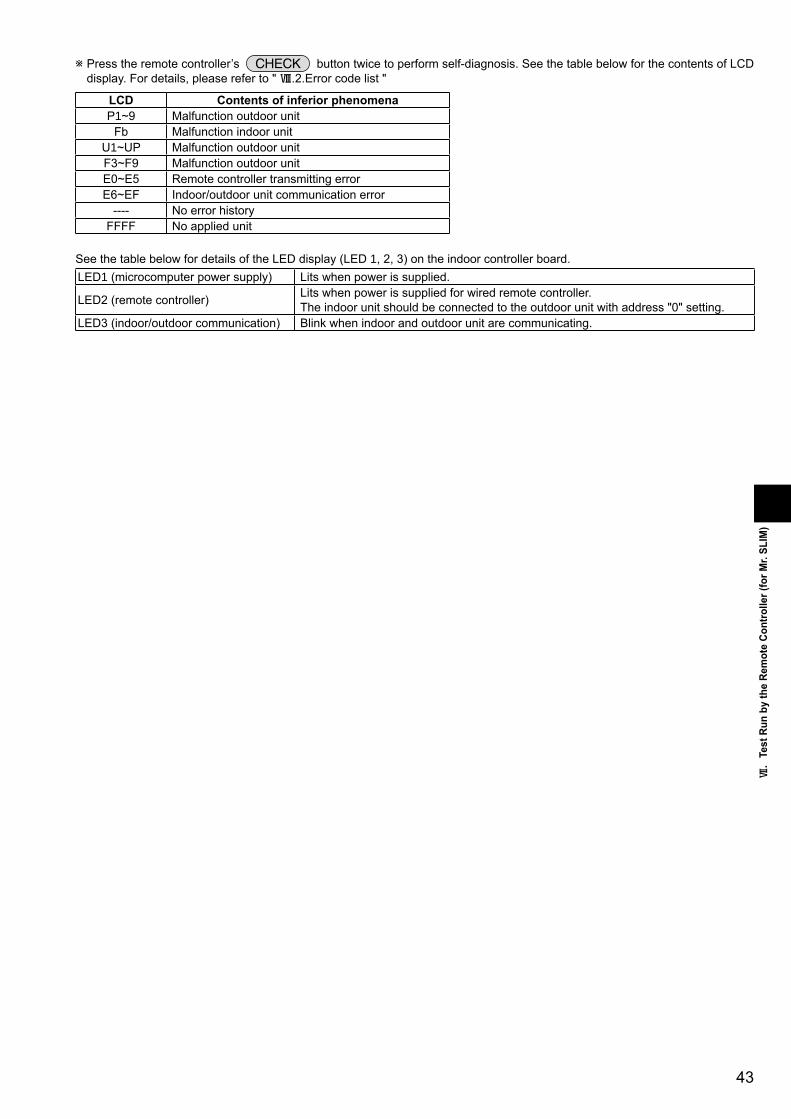
43
&.
Test
Run
by
the
Rem
ote
Cont
rolle
r(fo
rMr.
SLIM
)
wPresstheremotecontroller’s buttontwicetoperformself-diagnosis.SeethetablebelowforthecontentsofLCDdisplay.Fordetails,pleasereferto"*.2.Errorcodelist"
LCD ContentsofinferiorphenomenaP�~9 Malfunctionoutdoorunit
Fb MalfunctionindoorunitU�~UP MalfunctionoutdoorunitF3~F9 MalfunctionoutdoorunitE0~E5 RemotecontrollertransmittingerrorE6~EF Indoor/outdoorunitcommunicationerror
---- NoerrorhistoryFFFF Noappliedunit
SeethetablebelowfordetailsoftheLEDdisplay(LED�,2,3)ontheindoorcontrollerboard.LED�(microcomputerpowersupply) Litswhenpowerissupplied.
LED2(remotecontroller) Litswhenpowerissuppliedforwiredremotecontroller.Theindoorunitshouldbeconnectedtotheoutdoorunitwithaddress"0"setting.
LED3(indoor/outdoorcommunication) Blinkwhenindoorandoutdoorunitarecommunicating.

44
1. How To Proceed "Self-Diagnosis"1-1. When a Problem Occurs During OperationIf a problem occurs in the air conditioner, the indoor and outdoor units will stop,and the problem is shown in the remote controller display.[CHECK] and the refrigerant address are displayed on the temperature
display, and the error code and unit number are displayed alternately asshown below.
(If the outdoor unit is malfunctioning, the unit number will be "00".) In the case of group control, for which one remote controller controls
multiple refrigerant systems, the refrigerant address and error code of theunit that first experienced trouble (i.e., the unit that transmitted the errorcode) will be displayed.
To clear the error code, press the ON/OFF button.
When using remote operation of remote/local combined control, clear the error code by pressing the button onremote controller after changing operation from remote to local.
ON/OFF
During central control by a MELANS controller, clear the error code by pressing the button on MELANS remote controller.
ON/OFF
1-2. Self-Diagnosis During Maintenance or ServiceSince each unit has a function that stores error codes, the latest check code can be recalled even if it is cancelled by the remotecontroller or power is shut off.
Check the error code history for each unit using the remote controller.Switch to self-diagnosis mode.
Press the CHECK button twice within 3 seconds. The display contentwill change as shown below.
Set the unit number or refrigerant address you want to diagnose.
Press the [TEMP] buttons ( and ) to select the desired numberor address. The number (address) changes between [01] and [50] or [00]
Display self-diagnosis results.<When there is error code history>(For the definition of each error code, refer to the indoor unit's installation manual or service handbook.)
Reset the error history.Display the error history in the diagnosis result display screen (see step ).
Error code (2 or 4 digits)
(Alternating Display)
Address (3 digits) or unit number (2 digits)
The refrigerant address will begin to blinkapproximately 3 seconds after beingselected and the self-diagnosis process will begin.
Unit number or refrigerant addressto be diagnosed
Error code (2 or 4 digits)
(Alternating Display)
Address (3 digits) or unit number (2 digits)
<When there is no error code history> <When there is no corresponding unit>
and [15].
*.Self-DiagnosisbytheRemoteController(forMr.SLIM)

45
*.
Self-
Diag
nosis
byth
eRem
oteC
ontro
ller(
forM
r.SLIM
)
Transmission data from remote controllerTransmission data on transmission path
When the number of data errors is "02":
Press the ON/OFF button twice within 3 seconds. The self-diagnosisaddress or refrigerant address will blink.
When the error history is reset, the display will look like the one shown below.However, if you fail to reset the error history, the error content will be displayed again.
Cancel self-diagnosis.Self-diagnosis can be cancelled by the following 2 methods.Press the CHECK button twice within 3 seconds. Self-diagnosis will be cancelled and the screen will return to the previous state in effect before the start
of self-diagnosis.Press the ON/OFF button. Self-diagnosis will be cancelled and the indoor unit will stop.
1-3. Remote Controller DiagnosisIf the air conditioner cannot be operated from the remote controller, diagnose the remote controller as explained below.
First, check that the power-on indicator is lit.If the correct voltage (DC12 V) is not supplied to the remote controller, theindicator will not light.If this occurs, check the remote controller's wiring and the indoor unit.
Switch to the remote controller self-diagnosis mode.Press the CHECK button for 5 seconds or more. The display content will
change as shown below.
Press the FILTER button to start self-diagnosis.
Remote controller self-diagnosis result
[When the remote controller is functioning correctly]
Check for other possible causes, as there is no problem with the remotecontroller.
[When the remote controller malfunctions](Error display 1) "NG" blinks. The remote controller's transmitting-receiv-
ing circuit is defective.
The remote controller must be replaced with a new one.
[Where the remote controller is not defective, but cannot be operated.](Error display 2) [E3], [6833] or [6832] blinks. Transmission is not possible.
There might be noise or interference on the transmission path, or the indoor unitor other remote controllers are defective. Check the transmission path and othercontrollers.
(Error display 3) "ERC" and the number of data errors are displayed. Data error has occurred.
The number of data errors is the difference between the number of bits sent fromthe remote controller and the number actually transmitted through the transmis-sion path. If such a problem is occurring, the transmitted data is affected by noise,etc. Check the transmission path.
To cancel remote controller diagnosisPress the CHECK button for 5 seconds or more. Remote controller diagnosis will be cancelled, "PLEASE WAIT" and operation lamp will blink. Afterapproximately 30 seconds, the state in effect before the diagnosis will be restored.
Power on indicator

46
F3F5F9
(EA)
(Eb)
(EC)
E6
E7
(E8)
(E9)
E0
E3
E4
E5
EF
Ed
A0~A8
[Display](1)Normal condition
(2)Abnormal condition
Unit conditionOutdoor controller board A-Control Service Tool
LED1 (Green) LED2 (Red) Error code
When the power is turned onWhen unit stopsWhen compressor is warming upWhen unit operates
Lighted LightedLightedLightedLighted
Not lighted
Indication of the displayAlternately blinking display
Operation modeNot lighted
Lighted
00, etc.08, etc.
C5, H7 etc.
Indication ErrorErrorcode 1
Outdoor controller boardContents Inspection method
LED1 (Green) LED2 (Red)1 blinking 2 blinking
2 blinking 1 blinking
2 blinking
3 blinking
4 blinking
5 blinking
Connector(63L) is open.Connector(63H) is open.2 connectors are open.
Startup time over
Error code is not defined.
Miswiring of indoor/outdoor unit conne-cting wire, excessive number of indoor units (4 units or more)Miswiring of indoor/outdoor unit co-nnecting wire (converse wiring or di-sconnection)
Indoor/outdoor unit communication error(signal receiving error) is detected by in-door unit. Indoor/outdoor unit communication error(transmitting error) is detected by indoorunit.Indoor/outdoor unit communication error(signal receiving error) is detected by outdoor unit.Indoor/outdoor unit communication error (transmitting error) is detected by outdoorunit.Remote controller signal receiving error is detected by remote controller.
Remote controller transmitting error is detected by remote controller.
Remote controller signal receiving error is detected by indoor unit.
Remote controller transmitting error is detected by indoor unit.
Serial communication error<Communication between outdoor controller board and outdoor power board><Communication between outdoor controller board and M-NET P.C. board>Communication error of M-NET system
1.Error code displayed on remote controller.Error codes given in ( ) are not displayed on remote controller.
Check if indoor/outdoor connecting wire is connected correctly.Check if 4 or more indoor units are connected to outdoor unit.
Check if noise entered into indoor/outdoor connecting wire or power supply. Re-check error by turning off power, and on again.
Check if connector (63L or 63H) on the outdoor controller board is not disconnected. Check continuity of pressure switch (63L or 63H) by tester.
Check if connector (CN4) on outdoor controller board and outdoor power board is not disconnected.
Check if there is poor connection of connector on outdoor controller board(CNMNT and CNVMNT).
Check M-NET communication signal.
Check if remote controller is MA remote controller(PAR-21MAA).Check if noise entered into transmission wire of remote controller.Check if noise entered into indoor/outdoor connecting wire.Re-check error by turning off power, and on again.
Check if connecting wire of indoor unit or remote controller is connected correctly.
Check if noise entered into transmission wire of remote controller. Re-check error by turning off power, and on again.
Check if indoor/outdoor connecting wire is connected correctly. Check if noise entered into indoor/outdoor connecting wire or power supply. Check if noise entered into indoor/outdoor controller board. Re-check error by turning off power, and on again.
<Displayfunctionofinspectionforoutdoorunit>TheblinkingpatternsofbothLED�(green)andLED2(red)indicatethetypesofabnormalitywhenitoccurs.Typesofabnormality can be indicated in details by connecting an optional part A-Control Service Tool (PAC-SK52ST) to connector CNM onoutdoorcontrollerboard.
2.ErrorCodeList(forMr.SLIM)

47
Indication ErrorOutdoorcontrollerboard
ContentsErrorcodeW�
InspectionmethodLED�(Green) LED2(Red)
3blinking �blinking Abnormalityofshellthermistor(TH32)anddischargingtemperature(TH4)
U2 1Checkifstopvalvesareopen.2Checkifconnectors(TH4,TH32,LEV-AandLEV-B)on
outdoorcontrollerboardarenotdisconnected.3Check if unit fills with specified amount of refrigeran4Measureresistancevaluesamongterminalsonindoor
valve and outdoor linear expansion valve with a tester.
Abnormalityofsuperheatduetolowdis-chargetemperature
U7
2blinking Abnormalhighpressure(Highpressureswitch63Hworked.)
U� 1Checkifindoor/outdoorunitshaveashortcycleontheirairducts.
2Checkifconnector(63H)onoutdoorcontrollerboardisnotdisconnected.
3Check if heat exchanger and filter is not dirt .4Measureresistancevaluesamongterminalsonlinear
expansion valve with a tester.3blinking Abnormalityofoutdoorfanmotorrotational
speedU8 1Checktheoutdoorfanmotor.
Protectionfromoverheatoperation(TH3) Ud4blinking Compressorovercurrentbreaking(Start-up
locked)UF 1Checkifstopvalvesareopen.
2Checklooseness,disconnection,andconversecon-nectionofcompressorwiring.
3Measureresistancevaluesamongterminalsoncom-pressorwithatester.
4Checkifoutdoorunithasashortcycleonitsairduct.
Compressorovercurrentbreaking UPAbnormalityofcurrentsensor(P.B.) UHAbnormalityofpowermodule U6
5blinking Open/shortofdischargethermistor(TH4)andshellthermistor(TH32)
U3 1Checkifconnectors(TH3,TH4,TH7/6,TH32)onout-doorcontrollerboardandconnector(CN3)onoutdoorpowerboardarenotdisconnected.
2MeasureresistancevalueofoutdoorthermistorsOpen/shortofoutdoorthermistors(TH3,TH6,TH7andTH8)
U4
6blinking Abnormalityofheatsinktemperature U5 1Checkifindoor/outdoorunitshaveashortcycleontheirairducts.
2Measureresistancevalueofoutdoorthermistor(TH8).7blinking Abnormalityofvoltage U9 1Checklooseness,disconnection,andconversecon-
nectionofcompressorwiring.2Measureresistancevalueamongterminalsoncom-
pressorusingatester.3Checkthecontinuityofcontactor(52C).4Checkifpowersupplyvoltagedecreases.5CheckthewiringofCN52C.6CheckthewiringofCNAF.
4blinking �blinking Abnormalityofroomtemperaturethermis-tor(TH�)
P� 1Checkifconnectors(CN20,CN2�,CN29andCN44)onindoorcontrollerboardarenotdisconnected.
2Measureresistancevalueofindoorthermistors.Abnormalityofpipetemperaturethermistor/Liquid(TH2)
P2
Abnormalityofpipetemperaturethermis-tor/Condenser-Evaporator
P9
2blinking Abnormalityofdrainsensor(DS)Floatswitch(FS)connectoropen
P4 1Checkifconnector(CN3�,CN4F)onindoorcontrollerboardisnotdisconnected.
2Measureresistancevalueofindoorthermistors.3Measureresistancevalueamongterminalsondrain-up
machineusingatester.4Checkifdrain-upmachineworks.5Checkdrainfunction.
Indoor drain overflow protectio P5
3blinking Freezing(cooling)/overheating(heating)protection
P6 1Checkifindoorunithasashortcycleonitsairduct.2Check if heat exchanger and filter is not dirt .3Measureresistancevalueonindoorandoutdoorfan
motors.4Checkiftheinsideofrefrigerantpipingisnotclogged.
4blinking Abnormalityofpipetemperature P8 1Checkifindoorthermistors(TH2andTH5)arenotdisconnectedfromholder.
2Checkifstopvalveisopen.3Check converse connection of extension pipe. (on
pluralunitsconnection)4Checkifindoor/outdoorconnectingwireisconnected
correctly.(onpluralunitsconnection)5blinking AbnormalityofIndoorcontrollerboard Fb 1Replaceindoorcontrollerboard.
— — Abnormalityofremotecontrollerboard E�,E2 1Replacetheremotecontroller.
W�.Errorcodedisplayedonremotecontroller.Errorcodesgivenin()arenotdisplayedonremotecontroller.

48
Turn on the [Monitoring the operation data]
(1)
(2)
(3)
(4)
(5)
(6)
(7)
(1) Press the TEST button for 3 seconds so that [Maintenance mode] appears on the screen (at ).
(2) Press the CHECK button for 3 seconds to switch to [Maintenance monitor].Note) It is not possible to switch to [Maintenance monitor] during data request in maintenance mode (i.e., while "- - - -" is blinking),
since no buttons are operative.
Operating the service inspection monitor- - - ] appears on the screen (at ) when [Maintenance monitor] is activated.
(The display (at ) now allows you to set a request code No.)(3) Press the [TEMP] buttons ( and ) to select the desired refrigerant address.
[Screen ]
(4) Press the [CLOCK] buttons ( and ) to set the desired request code No.
(5) Press the FILTER button to perform data request.(The requested data will be displayed at in the same way as in maintenance mode.)
Data collected during operation of the remote controller will be displayed.The collected data such as temperature data will not be updated automatically even if the data changes.To display the updated data, carry out step (4) again.
Canceling the Monitoring the operation data(6) While [Maintenance monitor] is displayed, press the CHECK button for 3 seconds to return to maintenance mode.
(7) To return to normal mode, press the ON/OFF button.
Example) Request code "004"Discharge temperature 69°CRefrigerant address "00"
B: Refrigerant addressC: Data display areaD: Request code display area
[
(.MonitoringtheOperationDatabytheRemoteController(forMr.SLIMPUHZseries)
1.Howto"MonitortheOperationData"

49
(.
Monit
oring
theO
perat
ionDa
taby
ther
emote
Contr
oller
(forM
r.SLIM
)
2.RequestCodeList*Certainindoor/outdoorcombinationsdonothavetherequestcodefunction;therefore,norequestcodesaredisplayed.
Req
uest
cod
e
Request contentDescription
(Display range)Unit Remarks
0123456789101112131415161718
19
20
2122232425262728293031
32
33
34
35
3637383940414243444546474849
Operation stateCompressor-Operating current (rms)Compressor-Accumulated operating timeCompressor-Number of operation timesDischarge temperature (TH4)Outdoor unit - Liquid pipe 1 temperature (TH3)Outdoor unit - Liquid pipe 2 temperatureOutdoor unit-2-phase pipe temperature (TH6)
Outdoor unit-Outside air temperature (TH7)Outdoor unit-Heatsink temperature (TH8)
Discharge superheat (SHd)Sub-cool (SC)
Compressor-Operating frequencyCompressor-Target operating frequencyOutdoor unit-Fan output stepOutdoor unit-Fan 1 speed(Only for air conditioners with DC fan motor)Outdoor unit-Fan 2 speed(Only for air conditioners with DC fan motor)
LEV (A) openingLEV (B) opening
Primary currentDC bus voltage
Number of connected indoor unitsIndoor unit-Setting temperatureIndoor unit-Intake air temperature <Measured by thermostat>Indoor unit-Intake air temperature (Unit No. 1)<Heat mode-4-deg correction>Indoor unit-Intake air temperature (Unit No. 2)<Heat mode-4-deg correction>Indoor unit-Intake air temperature (Unit No. 3)<Heat mode-4-deg correction>Indoor unit-Intake air temperature (Unit No. 4)<Heat mode-4-deg correction>
Indoor unit - Liquid pipe temperature (Unit No. 1)Indoor unit - Liquid pipe temperature (Unit No. 2)Indoor unit - Liquid pipe temperature (Unit No. 3)Indoor unit - Liquid pipe temperature (Unit No. 4)
Indoor unit-Cond./Eva. pipe temperature (Unit No. 1)Indoor unit-Cond./Eva. pipe temperature (Unit No. 2)Indoor unit-Cond./Eva. pipe temperature (Unit No. 3)Indoor unit-Cond./Eva. pipe temperature (Unit No. 4)
Thermostat ON operating timeTest run elapsed time
Refer to 2-1. Detail Contents in Request Code.0 – 500 – 99990 – 99993 – 217-40 – 90-40 – 90-39 – 88
-39 – 88-40 – 200
0 – 2550 – 130
0 – 2550 – 2550 – 10
0 – 9999
0 – 9999
0 – 5000 – 500
0 – 50180 – 370
0 – 417 – 308 – 398 – 39
8 – 39
8 – 39
8 – 39
-39 – 88-39 – 88-39 – 88-39 – 88
-39 – 88-39 – 88-39 – 88-39 – 88
0 – 9990 – 120
–A
10 hours100 times
Outdoor unit-Suction pipe temperature (TH32) PUHZ-HRP type-39 – 88
HzHz
Step
rpm
rpm
PulsesPulses
LEV (C) opening 0 – 500 PulsesAV
Units
MinutesMinutes
"0" is displayed if the air conditioner is a single-fantype.
"0" is displayed if the target unit is not present.
"0" is displayed if the target unit is not present.
"0" is displayed if the target unit is not present.
Not possible to activate maintenance mode during the test run.

50
Req
uest
cod
e
Request contentDescription
(Display range)Unit Remarks
50515253545556575859606162636465666768697071727374757677787980818283
84
85868788
89
90
91
9293949596979899
100
101
102
Indoor unit-Control stateOutdoor unit-Control stateCompressor-Frequency control stateOutdoor unit-Fan control stateActuator output stateError content (U9)
Signal transmission demand capacityContact demand capacityExternal input state (silent mode, etc.)
Outdoor unit-Capacity setting displayOutdoor unit-Setting information
Outdoor unit-SW1 setting informationOutdoor unit-SW2 setting information
Outdoor unit-SW4 setting informationOutdoor unit-SW5 setting informationOutdoor unit-SW6 setting informationOutdoor unit-SW7 setting informationOutdoor unit-SW8 setting informationOutdoor unit-SW9 setting informationOutdoor unit-SW10 setting information
M-NET adapter connection (presence/absence)
Display of execution of replace/wash operation
Outdoor unit-Microcomputer version information
Outdoor unit-Microcomputer version information (sub No.)
Outdoor unit - Error postponement history 1 (latest)
Outdoor unit - Error postponement history 2 (previous)
Outdoor unit - Error postponement history 3 (last but one)
0 – 255
"0000": Not connected
Examples) Ver 5.01 Auxiliary information (displayed afterversion information)Examples) Ver 5.01 A000
Displays postponement code. (" - - " isdisplayed if no postponement code is present)Displays postponement code. (" - - " isdisplayed if no postponement code is present)Displays postponement code. (" - - " isdisplayed if no postponement code is present)
––––––
%––
––
––
–––––––
–
–
Ver
–
Code
Code
Code
Refer to 2-1.Detail Contents in Request Code.
Refer to 2-1.Detail Contents in Request Code.Refer to 2-1.Detail Contents in Request Code.
Refer to 2-1.Detail Contents in Request Code.
Refer to 2-1.Detail Contents in Request Code.
Refer to 2-1.Detail Contents in Request Code.
Refer to2-1.Detail Contents in Request Code.
Refer to 2-1.Detail Contents in Request Code.
Refer to 2-1.Detail Contents in Request Code.
Refer to 2-1.Detail Contents in Request Code.
Refer to 2-1.Detail Contents in Request Code.
Refer to 2-1.Detail Contents in Request Code.
Refer to 2-1.Detail Contents in Request Code.
Refer to 2-1.Detail Contents in Request Code.
Refer to 2-1.Detail Contents in Request Code.
Refer to 2-1.Detail Contents in Request Code.
Refer to 2-1.Detail Contents in Request Code.
Refer to 2-1.Detail Contents in Request Code.
Refer to 2-1.Detail Contents in Request Code.
"0001": Connected
"0000": Not washed"0001": Washed
"0501"
"A000"

5�
Req
uest
cod
eRequest content
Description(Display range)
Unit Remarks
103104105
106
107108109110111112113114115116117118119120
121
122
123
124125126127128129130131
132
133
134
135136137138139140~
146147148149150151152
Displays error history. (" - - " is displayed if no history is present.)Displays error history. (" - - " is displayed if no history is present.)Displays error history. (" - - " is displayed if no history is present.)
: TH36 : TH67 : TH78 : TH80 : No thermistor error
Displayed in the same way as request code "0".0 – 500 – 99990 – 99993 – 217-40 – 90-40 – 90-39 – 88
-39 – 88-40 – 2000 – 2550 – 1300 – 255
0 – 10
0 – 9999
0 – 9999
0 – 5000 – 500
0 – 999
-39 – 88
-39 – 88
-39 – 88
-39 – 88-39 – 88-39 – 88
CodeCodeCode
Sensornumber
–A
10 hours100 times
Hz
Step
rpm
rpm
PulsesPulses
Minutes
"0" is displayed if the air conditioner is a single-fan type.
Average value of all indoor units is displayed if the air condi-tioner consists of two or more indoor units (twin, triple, quad).Average value of all indoor units is displayed if the air condi-tioner consists of two or more indoor units (twin, triple, quad).
Error history 1 (latest)Error history 2 (second to last)Error history 3 (third to last)
Abnormal thermistor display(TH3/TH6/TH7/TH8)
Operation mode at time of errorCompressor-Operating current at time of errorCompressor-Accumulated operating time at time of errorCompressor-Number of operation times at time of errorDischarge temperature at time of errorOutdoor unit - Liquid pipe 1 temperature (TH3) at time of error
Outdoor unit - Liquid pipe 2 temperature at time of errorOutdoor unit-2-phase pipe temperature (TH6) at time of error
Outdoor unit-Outside air temperature (TH7) at time of errorOutdoor unit-Heatsink temperature (TH8) at time of errorDischarge superheat (SHd) at time of errorSub-cool (SC) at time of errorCompressor-Operating frequency at time of errorOutdoor unit at time of error• Fan output stepOutdoor unit at time of error• Fan 1 speed (Only for air conditioners with DC fan)Outdoor unit at time of error• Fan 2 speed (Only for air conditioners with DC fan)
LEV (A) opening at time of errorLEV (B) opening at time of error
Thermostat ON time until operation stops due to error
Indoor - Liquid pipe temperature at time of error
Indoor-2-phase pipe temperature at time of error
Indoor at time of error• Intake air temperature <Thermostat judge temperature>
Indoor-Actual intake air temperatureIndoor - Liquid pipe temperatureIndoor-2-phase pipe temperature
3

52
Req
uest
cod
e
Request contentDescription
(Display range)Unit Remarks
153
154
155
156157
158
159160161162163164165166167~
189190191
192~
764765766
767
0 – 9999
0 – 9999
0 – 255 Fan control data
00 **" "**" indicates fan control data.
"00 **" "**" indicates fan control data.
Refer to 2-1. Detail Contents in Request Code.UndefinedRefer to 2-1. Detail Contents in Request Code.
Undefined
Examples) Ver 5.01 "0501"Auxiliary information (displayed after version information)Examples) Ver 5.01 A000 "A000"
1 hour
10 hours
–
–
–
–––––
Ver
–
For indoor fan phase control
For indoor fan pulsation control
For indoor DC brushless motor control
Indoor-Fan operating time(After filter is reset)Indoor-Total operating time(Fan motor ON time)
Indoor fan output value (Sj value)Indoor fan output value(Pulsation ON/OFF)Indoor fan output value (duty value)
Indoor unit-Model setting informationIndoor unit-Capacity setting informationIndoor unit-SW3 informationWireless pair No. (indoor control board side) settingIndoor unit-SW5 information
Indoor unit-Microcomputer version informationIndoor unit-Microcomputer version information (sub No.)
Stable operation (Heat mode)Stable operation (Cool mode)
Stable operation cancellation
This request code is not provided to collect data. It is used to fix the operation state.This request code is not provided to collect data. It is used to fix the operation state.This request code is not provided to collect data. It is used to cancel the operation state that has beenfixed by request codes "765" and "766".
"
Refer to 2-1. Detail Contents in Request Code.

53
Frequency control state
Display Discharge temperature Condensation temperature Anti-freeze Heat sink temperatureoverheat prevention overheat prevention protection control overheat prevention
01 Controlled2 Controlled3 Controlled Controlled4 Controlled5 Controlled Controlled6 Controlled Controlled7 Controlled Controlled Controlled8 Controlled9 Controlled ControlledA Controlled Controlledb Controlled Controlled ControlledC Controlled Controlledd Controlled Controlled ControlledE Controlled Controlled ControlledF Controlled Controlled Controlled Controlled
[Operation state] (Request code "0")
Data display
Example) Request code "004"Discharge temperature69°CRefrigerant address "00"
B: Refrigerant addressC: Data display areaD: Request code display area
C 4Relay output stateOperation mode
[Indoor unit – Control state] (Request code :"50")
Data display
Operation mode
Display Operation mode0 STOP • FANC COOL • DRYH HEATd Defrost
Relay output state
Display Power currently Compressor Four-way valve Solenoid valvesupplied to compressor
Unit No. 4 stateUnit No. 3 state
Unit No. 2 state
Unit No. 1 state
Display State0 Normal1 Preparing for heat operation.2 –3 –4 Heater is ON.5 Anti-freeze protection is ON.6 Overheat protection is ON.7 Requestingcompressor to turnOFF.F There are no corresponding units.
[Outdoor unit – Control state] (Request code "51")
Data display State0 0 0 0 Normal0 0 0 1 Preparing forheatoperation.0 0 0 2 Defrost
[Compressor – Frequency control state] (Request code "52")
Data display
0 0Frequency control state
Frequency control state
Frequency control state
Display Current limit control0 No current limit1 Primary current limit control is ON.2 Secondary current limit control is ON.
–
ONON
012345678A
–
ONONONON
–
ONON
ONON
ON
–ON
ON
ON
ON
2-1.DetailContentsinRequestCode

54
[Fan control state] (Request code :"53")
Data display
Fan step correction value by heat sink temperature overheat prevention controlFan step correction value by cool condensation temperature overheat prevention control
0 0
Display Correction value- (minus) – 1
0 0
2
[Actuator output state] (Request code :"54")
Data displayActuator output stateActuator output state
0 0
Actuator output state
Display SV1 Four-way valve Compressor
0123456789AbCdEF
ON
ON
ON
ON
ON
ON
ON
ON
ONON
ONON
ONON
ONON
ONONONON
ONONONON
ONONONONONONONON
Actuator output state
Display 52C SV2 SS
01234567
ON
ON
ON
ON
ONON
ONON
ONONONON
[Error content (U9)] (Request code :"55")
Data display
Error contentError content
0 0
Error content : Detected
Display Overvoltage Undervoltage L1-phase Power synchronizingerror error open error signal error
0123456789AbCdEF
Error content : Detected
Display Converter Fo PAM errorerror
0123
Compressor iswarming up
1 +1+2

55
[Contact demand capacity] (Request code "61")
Data display 0 0 0Setting content
[External input state] (Request code "62")
Data display 0 0 0Input state
Input state : Input present
Display Contact demand Silent mode Spare 1 Spare 2input input input input
0123456789AbCdEF
[Outdoor unit -–Capacity setting display] (Request code : "70")
Data display Capacity
10 509 35
11 6014 7120 10025 12528 14040 170/20050 250
[Outdoor unit – Setting information] (Request code "71")
Data displaySetting informationSetting information
0 0Setting information
Display Defrost mode0 Standard1 For high humidity
Setting information
Display Single-/ Heat pump/three-phase cooling only
0 Single-phase Heat pump1 Cooling only2 Three-phase Heat pump3 Cooling only
Setting content
Display Setting value SettingSW7-1 SW7-2
01 50% ON
ON2 75% ON
ON
0%
3 100%

56
SW1, SW2, SW6, SW71 2 3 4 5 60 0 0 0 0 0 00 001 0 0 0 0 0 00 010 1 0 0 0 0 00 021 1 0 0 0 0 00 030 0 1 0 0 0 00 041 0 1 0 0 0 00 050 1 1 0 0 0 00 061 1 1 0 0 0 00 070 0 0 1 0 0 00 081 0 0 1 0 0 00 090 1 0 1 0 0 00 0A1 1 0 1 0 0 00 0b0 0 1 1 0 0 00 0C1 0 1 1 0 0 00 0d0 1 1 1 0 0 00 0E1 1 1 1 0 0 00 0F0 0 0 0 1 0 00 101 0 0 0 1 00 1 0 0 1 01 1 0 0 1 00 0 1 0 1 01 0 1 0 1 00 1 1 0 1 01 1 1 0 1 00 0 0 1 1 01 0 0 1 1 00 1 0 1 1 01 1 0 1 1 00 0 1 1 1 01 0 1 1 1 00 1 1 1 1 01 1 1 1 1 00 0 0 0 0 11 0 0 0 0 10 1 0 0 0 11 1 0 0 0 10 0 1 0 0 11 0 1 0 0 10 1 1 0 0 11 1 1 0 0 10 0 0 1 0 11 0 0 1 0 10 1 0 1 0 11 1 0 1 0 10 0 1 1 0 11 0 1 1 0 10 1 1 1 0 11 1 1 1 0 10 0 0 0 1 11 0 0 0 1 10 1 0 0 1 11 1 0 0 1 10 0 1 0 1 11 0 1 0 1 10 1 1 0 1 11 1 1 0 1 10 0 0 1 1 11 0 0 1 1 10 1 0 1 1 11 1 0 1 1 10 0 1 1 1 11 0 1 1 1 10 1 1 1 1 11 1 1 1 1 1
[Outdoor unit switch setting display (SW1 to SW10, except SW3)] Request codes: 73 to 820: Swich OFF 1: Swich ON
Data displaySW5
1 2 3 40 0 0 0 00 001 0 0 0 00 010 1 0 0 00 021 1 0 0 00 030 0 1 0 00 041 0 1 0 00 050 1 1 0 00 061 1 1 0 00 070 0 0 1 00 081 0 0 1 00 090 1 0 1 00 0A1 1 0 1 00 0b0 0 1 1 00 0C1 0 1 1 00 0d0 1 1 1 00 0E1 1 1 1 00 0F
0: Swich OFF 1: Swich ON
Data display
SW81 2 30 0 0 00 001 0 0 00 010 1 0 00 021 1 0 00 030 0 1 00 041 0 1 00 050 1 1 00 061 1 1 00 07
0: Swich OFF 1: Swich ON
Data display
SW4, SW9, SW101 20 0 00 001 0 00 010 1 00 021 1 00 03
0: Swich OFF 1: Swich ON
Data display
00 1100 1200 1300 1400 1500 1600 1700 1800 1900 1A00 1B00 1C00 1D00 1E00 1F00 2000 2100 2200 2300 2400 2500 2600 2700 2800 2900 2A00 2B00 2C00 2D00 2E00 2F00 3000 3100 3200 3300 3400 3500 3600 3700 3800 3900 3A00 3B00 3C00 3D00 3E00 3F

57
[Indoor unit – Model setting information] (Request code : 162)
Data display
0 0
See the table on the right.
Display Model setting state Display Model setting state
00 PSA-RP•GA, PSH-PGAH 2001 21 PKA-RP•FAL(2), PKH-P•FALH02 PEAD-RP•EA(2)/GA, PEHD-P•EAH 22 PCA-RP•GA(2), PCH-P•GAH, PLA-RP•BA(2)03 SEZ-KA•VA 2304 2405 SLZ-KA•VA(L) 2506 PCA-RP•HA 2607 2708 2809 290A 2A0b 2b PKA-RP•GAL, PKH-P•GALH0C 2C0d 2d0E 2E0F 2F PLA-RP• AA10 3011 PEA-RP•EA
PEA-RP400/500GA
PEA-RP200/250GA
31 PLH-P•AAH
PLA-RP•AA2
12 MEXZ-GA•VA(L) 3213 3314 3415 3516 3617 3718 3819 391A 3A1b 3b1C 3C1d 3d1E 3E1F 3F
[Indoor unit – Capacity setting information] (Request code 163 )
Data display
0 0
See the table on the right.
Display Capacity setting state Display Capacity setting state
00 12 10 11201 16 11 12502 22 12 14003 25 1304 28 1405 32 1506 35, 36 1607 40 1708 45 1809 50 190A 56 1A0b 63 1b0C 71 1C0d 80 1d0E 90 1E0F 100 1F
Display Pair No. setting state
00 No. 001 No. 1 J41 disconnected02 No. 2 J42 disconnected03 No. 3 J41, J42 disconnected
[Wireless pair No. (indoor control board side) setting] (Request code 165 )
Data display
0 0
See the table on the right.

58
System Name System Diagram Features Parts Required in Addition to Standard SystemComponents (Indoor/Outdoor Units, Remote Controller)
Indoor unit
RemoteController
Outdoorunit
A.Remote control-ler operation(Standard)
B.Remote control-ler operation
Use of 2 con-trollers enablesoperation of the airconditioner bothfrom a distanceand nearby.
C.Group controloperation
Use of 1 remotecontroller to con-trol multiple airconditioners withthe same settingssimultaneously.
* Outdoor unit`s re-frigerant addressneeds to be set.
D.Remote/localcombined controloperation
Allows start/stopof the air condi-tioner from a dis-tance, and prohib-its/permits start/stop from remotecontrollers.
E.Operation byexternal signal
F.Control by externalsignal and remotedisplay
Enables you todisplay the op-eration state andcontrol start/stopfrom a distance.
There are 2 types of remote controllers: wired typeand wireless type.Simultaneous twin, triple and quad units are counted as 1 unit, and the indoor units are started or stopped simultaneously.
Up to 2 remote controllers can be connected toone group.Simultaneous twin, triple and quad units are counted as 1 unit.
Operation control by the latest command (last en-tered priority)Wired and wireless remote controllers can be com-bined as a pair.
One group can consist of up to 16 indoor units, andthey can be started sequentially by connecting theremote controller to them and assigning an addressto each outdoor unit.Simultaneous twin , triple and quad units are counted as 1 unit.All the units belonging to the same group are oper-ated in the same mode, but thermostats can beturned ON/OFF individually for each outdoor unit.Up to 2 remote controllers can be connected.
All the air conditioners can be turned ON/OFF collectivelyfrom a distance.Operation can be switched between the remote operat-ing panel and local controller.Operations (e.g., temperature adjustment, airflow, air-flow direction) except for start/stop operations can beperformed even if operations from the local remotecontroller are prohibited.In the case of simultaneous twin, triple, quad units, connect the controller to one indoor unit only. If connected to 2 or more indoor units, an error may occur.(operation stop)Control by an external timer is possible by connecting it.
Use of optional "remote ON/OFF adapter" enablesremote control via relay. (Level signal)
Extraction of non-voltage contact outputUse of optional "remote operation adapter" and"remote display panel" (Part to be provided at your site) provides non-voltage contact outputs ofsignals (operation, error) and operation/stop input function.
Extraction of DC12 V contact outputUse of optional "Multiple remote controller adapter"and "remote display panel" (Part to be provided at your site)provides DC12 V contact outputs of signals(operation, error) and operation/stop input function.
Indoorunit
RemoteController
* One of the wired remote con-trollers must be set as a subremote controller.
Outdoorunit
Indoorunit
RemoteController
Indoor unit
Remote Controller
Relay box
Remote operating panel
Adapter
Remote display panel(operation, error)
Indoor unit
Remote Controller
Wired remote controller (addi-tional)(PAR-21MAA)
For PKA type, use remote controller(PAR-21MAAT-E)
* For models equipped with aterminal block.
For PKA type, use remote controller(PAR-21MAAT-E)
* For models equipped with aterminal block.
Remote ON/OFF adapter(PAC-SE55RA-E)Relay box(Part to be provided at your site)Remote operating panel(Part to be provided at your site)
Remote ON/OFF adapter(PAC-SE55RA-E)
Remote operation adapter(PAC-SF40RM-E)Remote display panel(Part to be provided at your site)
Multiple remote controller adapter(PAC-SA88HA)Remote display panel(Part to be provided at your site)
).SystemControl(forMr.SLIM)VARIETYOFSYSTEMFUNCTION

59
).
Syst
emC
ontr
ol(f
orM
r.SLI
M)
Powersupplyunit
Outdoorunit
Indoorunit
RemoteController
Central controller, etc.
<Connection with M-NET system>
System Name System Diagram Features Parts Required in Addition to Standard SystemComponents (Indoor/Outdoor Units, Remote Controller)
G. Timer operationEnables controlof start and stop.
* For control by external timer,refer to Remote/local combined control operation".
H.Interlock opera-tion with periph-eral equipment
Enables control ofMitsubishi Lossnayventilator by remotecontroller.
I.Central control
• Weekly timer: In addition to ON/OFF, up to 8 temperature patterns can be set for each day of the week.
* Only one timer can be selected; the auto off, simpleand weekly timers cannot be combined.
• Simple timer: Start and stop operations can each beperformed once within 72 hours (canbe set in 1-hour increments).
• Auto off timer: Operation is stopped when the presettime elapses following the start ofoperation.The time can be set from 30 minutesto 4 hours in 30-minute increments.
* Only one timer can be selected; the simple and autooff timers cannot be combined.
• Connecting a Lossnay ventilator and an indoor unitenables control of interlock/solo ventilation opera-tion and airflow.(Only the microcomputer type Lossnay ventilatorcan be used.)
• Connecting the M-NET connection adapter to outdoorunit enables connection of MELANS system control-ler (for M-NET).
• When using A-control operation, the number ofindoor units in a MELANS system is limited to thenumber of outdoor units.(Simultaneous twin, triple and quad units are countedas 1 unit.)
• Number of controlled outdoor unitsCentral controller: 50 unitsGroup remote controller(PAC-SC30GR): 16 units
MA Remote controller(PAR-21MAA)
M-NET adapter (Option PARTS)Central controller(G-50A)Group remote controller(PAC-SC30GR), etc.
Indoor unit
RemoteController
Lossnayventilator
J.Demand control
Indoor unit
Outdoor unit
Adaptor to inputexternal demandsignal
Relay box
RemoteOperating panel
• Demand control is available by external input. In this mode, power consumption is decreased within the range of usual 0-100%.
Adapter to input externaldemand signals. (PAC-SC36NA)
K.Rotation
Relay box(Part to be provided at your site )
Remote operating panel(Part to be provided at your site)
• RotationMain and sub unit operate alternately according to the interval of roration setting.
• Back-upWhen abnormality occurs while operation, it changes into operating the backup unit, and operation is continued.
• 2nd stage cut-in· Number of operating units is determined according to the room temperature and set point.
· When room temperature becomes higher than set point, standby unit starts.(2 units operation)
· When room temperature falls below set point -4°C, standby unit stops.(1 unit operation)
• This function is available whenonly 2 indoor units are connected to each PUHZ type outdoor unit.
Application modelIndoor unitPLA-RP • BA2/BA#2.UKPCA-RP • GA(2)#1/HA#1PKA-RP • GAL#1/FAL(2)#1PSA-RP • GA#1PEAD-RP • EA(2)#1/GA#1

60
Slim Air Conditioners System
Sys
tem
dia
gram
(Wire
d re
mot
e c
ontro
ller )
Outdoor unit OC
Indoor unit IC
Wiredremotecontroller R
Indoor/Outdoorconnectioncable
Remotecontrollercable
OC
IC-1
R
IC-2
3
2
3OC
IC-1
R
3
2
Standard 1:1 Simultaneous Twin Simultaneous Triple Simultaneous Quad
L1
L2
L3
N
OCS1S2S3
S1S2S3
IC
12
12
R
(No polarity)
Outdoor unit Indoor unit Remote controller
Powersourcewiring
(Polarity)
Slim Air Conditioners System
Sys
tem
dia
gram
(Wire
less
rem
ote
con
trolle
r rec
eive
r)
Outdoor unit OC
Indoor unit IC
Wirelessremote controller receiver section R'
Indoor/Outdoorconnectioncable
OC
IC-1
R'
IC-2
3
9
3OC
IC-1
R'
3
9
Standard 1:1 Simultaneous Twin
S1 S2 S3
CN90
Controller board
Indoor unit IC
9
CNB
1 2
Wireless remote controller optical receiver section R’
Indoor/outdoorconnection cable terminal block
Remote controller cable terminal block
1-1 1 Wired Remote Controller(OC: Outdoor unit IC: Indoor unit R: Remote controller (for wireless type: optical receiver adapter)
(Reference) If simultaneous twin or triple or quad, connect the remote controller to any one of the indoor units. All functions of the
indoor unit can be controlled even if different models (different types) are mixed. Do not use crossover wiring among indoor units with simultaneous twin, triple, quad units. (Prohibited item.) Electrical wiring diagram
1-2 Wireless remote controller
(Reference) If simultaneous twin or triple or quad, connect the remote controller to any one of the indoor units. All functions of the indoor unit can be
controlled even if different models (different types) are mixed. Do not use crossover wiring among indoor units with simultaneous twin, triple, quad units. (Prohibited item.) Electrical wiring diagram
OC3(2) 3(2)
2
IC-1 IC-2 IC-3
R
3(2)
OC3(2) 3(2)
2
IC-1 IC-2 IC-3 IC-4
R
3(2) 3(2)
Simultaneous Quad
OC3(2) 3(2)
9
IC-1 IC-2 IC-3
R
3(2)
OC3(2) 3(2)
9
IC-1 IC-2 IC-3 IC-4
R
3(2) 3(2)
Simultaneous Triple
* Numbers given in ( ) apply when power is supplied to the indoor and outdoor units separately.
* Numbers given in ( ) apply when power is supplied to the indoor and outdoor units separately.
1. 1RemoteController(Standerd)Operation

6�
1-3 Wired Remote Controller or Wireless Remote Controller Receiver Built into Indoor Unit[Floor type (wired remote controller)/4-way ceiling cassette type, ceiling suspended type, wall mounted type (wireless remotecontroller)]
Slim Air Conditioner System Standard 1:1 Simultaneous Twin Simultaneous Triple Simultaneous Quad
[Reference]For systems containing built-in wired remote controllers (or built-in wireless receiver adapters) and consisting of simultaneous twin, triple and quadunits only, the installed remote controllers (or receiver adapters) must be connected without changing any settings. If the system consists ofdifferent models, keep only one of the remote controllers built into the indoor units, or remove all the remote controller cables and connect themto other models according to 1-1 or 1-2.Use the wired remote controllers without setting them as the main and sub controllers.
Syst
em d
iagr
am(W
ired
rem
ote
cont
rolle
r or w
irele
ss re
mot
econ
trol
ler
rece
iver
)Outdoor unitOC
Indoorunit IC
Wired remotecontroller orreciever R
OC
3(2)
ICR
Indoor/outdoorconnection cable
OC3(2) 3(2)
IC-1 IC-2R-1 R-2
OC3(2) 3(2)
IC-1 IC-2 IC-3R-1 R-2 R-3
3(2)
OC3(2) 3(2)
IC-1 IC-2 IC-3 IC-4R-1 R-2 R-3 R-4
3(2) 3(2)
* Numbers given in ( ) apply when power is supplied to the indoor and outdoor units separately.
2. 2-remote Controller Operation2-1 2 Wired Remote Controllers (R: Wired remote controller)
Slim Air Conditioner System Standard 1:1 Simultaneous Twin
[Reference]
Systemdiagram(Wiredremotecontroller)
Outdoor unit OC
Indoor unit IC
Wired remote controller R
Outdoor unit OC
Indoor unit IC
Wired remotecontroller R
Slim Air Conditioner System Simultaneous Triple Simultaneous Quad
Outdoor unit OC
Indoor unit IC
Wired remote controller R
Outdoor unit OC
Indoor unit IC
Wired remotecontroller R
OC
3(2)
2
IC
R-1 R-2
2Remotecontrollercable
Indoor/outdoorconnection cable
OC3(2) 3(2)
2
IC-1 IC-2
R-1 R-2
2
2
OC
2
IC
R-1 R-2
3(2)
OC
3(2)
2
IC-1 IC-2
R-1 R-22
3(2)
* Numbers given in ( ) apply when power is supplied to the indoor and outdoor units separately.
If simultaneous twin or triple or quad, connect the remote controller to any one of the indoor units. All functions of the indoor unit can be controlled even if different models (different types) are mixed. Do not use crossover wiring among indoor units with simultaneous twin, triple, quad units. (Prohibited item.)Set one of the remote controllers as the main controller (initial setting) and the other as the sub controller using the remote controller's function selection.
OC3(2) 3(2)
2
IC-1 IC-2 IC-3
R-1
3(2)
R-2
2
OC3(2) 3(2)
2
IC-1 IC-2 IC-3 IC-4
R-1
3(2) 3(2)
R-2
2
OC3(2)
2
IC-1 IC-2 IC-3
R-1
3(2)
R-22
3(2)
OC
3(2)
2
IC-1 IC-2 IC-3 IC-4
R-1
3(2)
R-2
2
3(2)3(2)
Systemdiagram(Wiredremotecontroller)
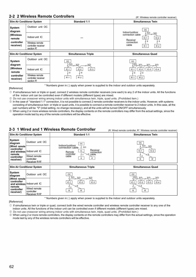
62
2-2 2 Wireless Remote ControllersSlim Air Conditioner System Standard 1:1 Simultaneous Twin
Systemdiagram(Wireless remote controller receiver)
Outdoor unit OC
Indoor unit IC
Wireless remote controller receiversection R'
—
OC3(2) 3(2)
IC-1 IC-2
R'-1 R'-2
9 9Receiverconnectioncable
Indoor/outdoorconnection cable
Slim Air Conditioner System Simultaneous Triple Simultaneous Quad
Outdoor unit OC
Indoor unit IC
Wireless remote controller receiversection R'
* Numbers given in ( ) apply when power is supplied to the indoor and outdoor units separately.[Reference]
2-3 1 Wired and 1 Wireless Remote Controller (R: Wired remote controller, R': Wireless remote controller receiver)
Slim Air Conditioner System Standard 1:1 Simultaneous Twin
Outdoor unit OC
Indoor unit IC
Wired remotecontroller Receiver R·R'
OC
3(2)
2
IC
R R'
9Remotecontrollercable
Indoor/outdoorconnection cable
Receiverconnectioncable
OC3(2) 3(2)
2
IC-1 IC-2
R R'
9
Slim Air Conditioner System Simultaneous Triple Simultaneous Quad
Outdoor unit OC
Indoor unit IC
Wired remotecontroller Receiver R·R'
* Numbers given in ( ) apply when power is supplied to the indoor and outdoor units separately.[Reference]
(R': Wireless remote controller receiver)
If simultaneous twin or triple or quad, connect 2 wireless remote controller receivers (one each) to any 2 of the indoor units. All the functions of the indoor unit can be controlled even if different models (different types) are mixed. Do not use crossover wiring among indoor units with simultaneous twin, triple, quad units. (Prohibited item.)In the case of "standard 1:1" connection, it is not possible to connect 2 remote controller receivers to the indoor units. However, with systems consisting of simultaneous twin or triple or quad units, it is possible to connect a remote controller receiver to 2 indoor units. In this case, all the pair numbers will be "0" (intial setting, no change necessary), and all the units will be turned ON/OFF simultaneously. When using 2 or more wireless remote controllers, the display contents on the remote controllers may differ from the actual settings, since the operation mode last by any of the remote controllers will be effective.
If simultaneous twin or triple or quad, connect both the wired remote controller and wireless remote controller receiver to any one of the indoor units. All the functions of the indoor unit can be controlled even if different models (different types) are mixed. Do not use crossover wiring among indoor units with simultaneous twin, triple, quad units. (Prohibited item.)When using 2 or more remote controllers, the display contents on the remote controllers may differ from the actual settings, since the operation mode last by any of the wireless remote controllers will be effective.
Systemdiagram(Wireless remote controller receiver)
Systemdiagram(Wired remote controllerand wireless remote controller receiver)
Systemdiagram(Wired remote controllerand wireless remote controller receiver)
OC3(2) 3(2)
IC-1 IC-2 IC-3
R'-1
3(2)
R'-2
9 9
OC3(2) 3(2)
9
IC-1 IC-2 IC-3 IC-4
R'-1
3(2) 3(2)
R'-2
9
OC3(2) 3(2)
2
IC-1 IC-2 IC-3
R
3(2)
R'
9
OC3(2) 3(2)
2
IC-1 IC-2 IC-3 IC-4
R
3(2) 3(2)
R'
9

63
3. Group Control Operation (Collective Operation and Control of Multiple Refrigerant Systems (2 to 16))
Multiple Mr.Slim air conditioners can be operated with the same settings (e.g., operation mode, preset temperature, etc.) by using 1 remotecontroller. Each outdoor unit can be turned ON/OFF individually by the intake sensor.Up to 16 refrigerant systems can be controlled as a group by 1 remote controller.A refrigerant address must be set for each outdoor unit. Addresses "0" to "15" can be set with no duplicates. Address "0" must be set for one ofthe outdoor units.
* In the case of simultaneous twin, triple and quad units, only 1 refrigerant system is used.
Slim AirConditionerSystem
Standard 1:1 2Standard 1:1
+ Simultaneous Twin
Sys
tem
dia
gram
(Wire
d rem
ote co
ntroll
er or
wire
less r
emote
contr
oller
receiv
er) Outdoor unitOC
Indoor unit IC
Wired remotecontroller R
Outdoor unitOC
Indoor unit IC
Wireless remote controller receiversection R'
OC-A
3(2)
2
IC-A
R
OC-B
3(2)
2
IC-BRemotecontrollercable
Indoor/outdoorconnection cable
Remotecontrollercrossoverwiring
2
R
OC3(2) 3(2)
IC-B1 IC-B2
OC-A
3(2)
IC-A
2
OC-A
3(2)
9
IC-A
R'
OC-B
3(2)
2
IC-B
Indoor/outdoorconnection cable
Remotecontrollercrossoverwiring
Receiverconnectioncable
9
R'
OC3(2) 3(2)
IC-B1 IC-B2
OC-A
3(2)
IC-A
2
* Numbers given in ( ) apply when power is supplied to the indoor and outdoor units separately.[Reference]
For 2-remote controller control, refer to "2. 2-Remote Controller Operation". However, when using both wired and wireless remote controllers, receivers must be connected to indoor units that are connected by crossover wiring.Connect an indoor unit having the highest functions among the group to the outdoor unit assigned to refrigerant address "0". <Refer to the examplegiven below> If indoor units with vanes are used with those without vanes, connect the outdoor unit to a unit with vanes.
Function specifications <Example>
In the case of multi type systems consisting of simultaneous twin, triple and quad units, the indoor units should not be connectedby crossover wiring. (Prohibited)
Outdoor unit address settingFor group control, an address must be set for each outdoor unit.To set addresses to outdoor units, use the DIP switch SW1 (3–6) provided on each outdoor control board (initial setting: all are set to "OFF").Address setting by SW1 is as follows.
* Checking the outdoor unit refrigerant addressesTo find the location of an outdoor unit with a specific refrigerant address, specify the address in self-diagnosis mode. The outdoorunit will operate intermittently. (For details on using self-diagnosis mode.)
Group operation by multiple remote controllersUp to 2 remote controllers can be connected to each group. For details, refer to " 2.2-REMOTE CONTROLLER OPERATION".
SW1Functionselection
123456
Function
Forced defrostingError history clearRefrigerant address setting
Operation by switchON OFF
Start NormalClear Normal
Used to set outdoor unit addresses("0" to "15").
Refrigerant address No.
Factory setting: All switches are set to OFF (i.e., refrigerant address "0").
noitcnuF
Item
Fan Number of fan speeds
Up/down Presence/absencevane Swing functionLeft/right swing louver Presence/absenceFunction order
delaecnocgnileCdetnuomllaWettessacgniliecyaw-4
PLA-RP.AAPLH-RP.AAH PLA-RP.BA(2) SLZ-KA.VA(L)
PSA-RP.GAPSH-RP.GAH PCA-RP.HA
PEAD-RP.EA(2)/GA
PEHD-RP.EAHSEZ-KA/KC.VA SEZ-KD.VA
Ceilingsuspended
Floormounted
Ceiling suspended(suitable for kitchen)
PCA-RP.GA(2)PCH-RP.GAH
PKA-RP.GALPKH-RP.GALH
PKA-RP.FAL(2)PKH-RP. FALH PEA-RP.EA(2)
<SW1>
OFF ON
15123456
OFF ON
14123456
OFF ON
13123456
OFF ON
12123456
OFF ON
11123456
OFF ON
10123456
OFF ON
9123456
OFF ON
8123456
OFF ON
7123456
OFF ON
6123456
OFF ON
5123456
OFF ON
4123456
OFF ON
3123456
OFF ON
2123456
OFF ON
1123456
OFF ON
0123456
OFF ON123456
Standard 1:1 +
Simultaneous Triple +
Simultaneous Twin
2
R
OC-A
3(2)
IC-A
2 2
OC-B3(2) )2(3)2(3
IC-B1 IC-B2 IC-B3
3(2)
OC-C3(2)
IC-CA IC-CB
9
R'
OC-A
3(2)
IC-A
2 2
OC-B3(2) )2(3)2(3
IC-B1 IC-B2 IC-B3
3(2)
OC-C3(2)
IC-CA IC-CB
4
1
4+Auto
1
3
2
4
1
4
1
2
3
2
4
2
6
2
6
2
6
2
6
3
5

64
Note:·WhentheuintisrestartedtooperateafterturningoffthepowerorOFFoperation,theunitwhichwasoperatingwill
startoperation.·Tooperatethemainunit,refertothe4-2.andsettherequetcodeNo.whichisnotthesameasthecurrentone,and
setagaintheformerrequestcodeNo.
(2)2ndstagecut-infunction•Outlineoffunctions
· When the 1st unit can NOT supply with sufficient capacity for exceptionally high-demand conditions and the actual room temperaturereachessetpoint*,the2ndunitstartsoperationinconjunctionwiththe�stunit.
·Oncetheactualroomtemperaturegoesdownto4degreesCbelowsetpoint*,the2ndunitstopsoperationautomatically.(*setpoint=settemperaturebyR/C(remotecontroller)+4,6,8:(selectable))
·Numberofoperatingunitsisdeterminedaccordingtotheroomtemperatureandsetpoint.·Whenroomtemperaturebecomeshigherthansetpoint,standbyunitstarts.(2unitsoperation)·Whenroomtemperaturefallsbelowsetpoint-4:,standbyunitstops.(�unitoperation)
4.RotationFunction(andback-upfunction,2ndstagecut-infunction)4-1.Operation(1)Rotationfunction(andBack-upfunction)•Outlineoffunctions
·Mainandsubunitsoperatealternatelyaccordingtotheintervalofrotationsetting.wMainandsubunitshouldbesetbyrefrigerantaddress.(OutdoorDipswitchsetting)
Refrigerantaddress"00" MainunitRefrigerantaddress"0�" Subunit
·Whenerroroccurrstooneunit,anotherunitwillstartoperation.(Back-upfunction)
•Systemconstraint·Thisfunctionisavailableonlybythegroupingcontrolsystem(INDOORUNIT:OUTDOORUNIT=�:�)of2refrigerant
groups.(RefertoFig.�)·Mainindoorunitshouldbeconnectedforwiredremotecontrollerandthetransmissionline(TB5)formainandsubunit
shouldalsobeconnected.(RefertoFig.�) (Thisfunctioncannotbesetbywirelessremotecontroller.)·Setrefrigerantaddressofeachunit.(Dipswitchontheoutdoorunit···Refrigerantaddress00/0�)
Operation pattern
OC-1 OC-2
IC-1 IC-2
3(2) 3(2)
2
RC
2
Mainunit
Subunit
Refrigerant address"01"
Refrigerant address"00"
Fig. 1[Back-up function only]··· Request code number "312"
[Rotation function] & [Back-up function]··· Request code number "313~318"
(Ex:When the request code number is "313", each unit operates alternately in daily cycle.)
Error occurs on main unit. Start operation
Run Abnormal condition
Stop Run
MainunitIC-1
SubunitIC-2
Error occurs on main unit.Start operation
1~28 days 1~28 days
RunAbnormal condition
Stop
Stop
Run
Run
Stop Run
MainunitIC-1
SubunitIC-2
Main Sub
Main Sub Sub Main Main Sub OC : Outdoor unitIC : Indoor unitRC : Wired remote controller

65
•Systemconstraint·Thisfunctionisavailableonlyincoolingmode.
[2nd stage cut-in function]··· Request code number "322~324"
Start operation Sub unit start operationRoom temp. Set point
Sub unit stop
Run
Stop StopRun
MainunitIC-1
SubunitIC-2
Room temp. < Set point -4
Ex.) Set temp. by R/C = 20::Setpoint=26::Whenrequestcodenumberis“323”.
26: 2ndunitCut-in
4degreeC
22: 2ndunitCut-out
20:
4-2.Howtosetrotationfunction(Back-upfunction,2ndstagecut-infunction)Youcansetthesefunctionsbywiredremotecontroller.(Maintenancemonitor)
Bothmainandsubunitshouldbesetinsamesetting.Everytimereplacingindoorcontrollerboardforservicing,thefunctionshouldbesetagain.
NOTICE
SettingNo.(Requestcode) Settingcontents Initial
settingNo.�(3�0) Monitoringtherequestcodeofcurrentsetting.
No.2(3��) RotationandBack-upOFF(Normalgroupcontroloperation)
No.3(3�2) Back-upfunctiononly
No.4(3�3) RotationON(Alternatinginterval=�day)andbackupfunction
No.5(3�4) RotationON(Alternatinginterval=3day)andbackupfunction
No.6(3�5) RotationON(Alternatinginterval=5day)andbackupfunction
No.7(3�6) RotationON(Alternatinginterval=7day)andbackupfunction
No.8(3�7) RotationON(Alternatinginterval=�4day)andbackupfunction
No.9(3�8) RotationON(Alternatinginterval=28day)andbackupfunction
SettingNo.(Requestcode) Settingcontents Initial
settingNo.�(320) Monitoringtherequestcodeofcurrentsetting.
No.2(32�) Cut-infunctionOFF
No.3(322) Cut-inFunctionON(Setpoint=Settemp.+4°C(7.2°F))
No.4(323) Cut-inFunctionON(Setpoint=Settemp.+6°C(�0.8°F))
No.5(324) Cut-inFunctionON(Setpoint=Settemp.+8°C(�4.4°F))
(1)RequestCodeList
Rotationsetting
2ndstagecut-insetting

66
(2) Setting method of each function by wired remote controller
B: Refrigerant addressC: Data display areaD: Request code display area
TEST
CHECK
FILTER
FILTER
ON/OFF
1. Stop operation( ).
2. Press the button ( ) for 3 seconds so that [Maintenance mode] appears on the screen ( ). After a while, [00] appears in the refrigerant address number display area.(at )
3. Press the button ( ) for 3 seconds to switch to [Maintenance monitor].Note) It is not possible to switch to [Maintenance monitor] during data request in maintenance mode
(i.e., while “----” is blinking) since no buttons are operative.
[----] appears on the screen ( ) when [Maintenance monitor] is activated.(The display ( ) now allows you to set a request code No.)
4. Press the [TEMP ( and )] buttons ( ) to select the desired refrigerant address.
5. Press the [CLOCK ( and )] buttons ( ) to set the desired request code No.(“311~318”, “321~324”)
6. Press the button ( ) to perform function setting. If above setting operations are done correctly, "Request code number" will appear in data display area.( ) [Example: When the "311" of "Request code number" is set, [311] appears on the screen.( )]
[Refererence]You can check current "request code number" setting by setting the "request code number"(“310” or “320”) and pressing the button.( )[Example: When the current setting is "Setting No.2(Request code 311)", [311] appears on the screen.( )]
7. To return to normal mode, press the button ( ).
[ScreenB]

67
( .Ext
erna
lDim
ensi
ons
83.5
130
46
120
19
(
.ExternalDimensions
External colors : Cover Pure white (Munsell 6.9Y 8.9/0.4)
LCDperipheralarea Mediumgray
unit:mm

MEMO

MEMO

MEMO

MEMO

MEMO


New publication effective Mar 2005.Issued in Mar. 2005 M-P0254A SIZ<MEE>Printed in Japan
Revised publication, Aug 2008. <REVISED>