M4000 Standard and M4000 Standard...
22
OPERATING INSTRUCTIONS M4000 Standard and M4000 Standard A/P Multiple Light Beam Safety Device GB
Transcript of M4000 Standard and M4000 Standard...
O P E R A T I N G I N S T R U C T I O N S
M4000 Standard andM4000 Standard A/P
Multiple Light Beam Safety Device
GB

Operating Instructions
M4000 Std., Std. A/P
2 © SICK AG • Industrial Safety Systems • Germany • All rights reserved 8011195/PE79/04-11-05
This document is protected by the law of copyright, whereby all rights established therein remain with thecompany SICK AG. Reproduction of this document or parts of this document is only permissible within the limitsof the legal determination of Copyright Law. Alteration or abridgement of the document is not permitted withoutthe explicit written approval of the company SICK AG.

Operating Instructions Chapter 2
M4000 Std., Std. A/P
8011195/PE79/04-11-05 © SICK AG • Industrial Safety Systems • Germany • All rights reserved 9
On safety
2 On safetyThis chapter deals with your own safety and the safety of the equipment operators.
Please read this chapter carefully before working with the M4000 multiple light beamsafety device or with the machine protected by the M4000 multiple light beam safetydevice.
2.1 Specialist personnelThe M4000 multiple light beam safety device must only be installed, commissioned andserviced by specialist personnel. Specialist personnel are defined as persons who
have undergone the appropriate technical training
and
who have been instructed by the responsible machine operator in the operation of themachine and the current valid safety guidelines
and
who have access to these operating instructions.
2.2 Applications of the deviceThe M4000 system is a type 4 electro-sensitive protective equipment (ESPE) as defined byIEC/EN 614961 and IEC 614962 and is therefore allowed for use with controls incategory 4 according to EN 9541. The M4000 multiple light beam safety device is usedfor:
hazardous area protection
access protection
The multiple light beam safety devices must be installed such that the hazardous area canonly be reached by interrupting the light path between sender and receiver. It must not bepossible to start the plant/system as long as personnel are within the hazardous area.
The M4000 system is intended only for use in industrial environments. When used inresidential areas it can cause interference.
Please refer to page 15 for an illustration of the protection modes and an exampleapplication.
Only use the multiple light beam safety device as an indirect protective measure!
An opto-electronic protective device like the M4000 system cannot provide any protectionagainst parts thrown out or against radiation. Transparent objects are not detected.
Depending on the application, mechanical protective devices may be required in additionto the M4000 system.
WARNING
Chapter 2 Operating Instructions
M4000 Std., Std. A/P
10 © SICK AG • Industrial Safety Systems • Germany • All rights reserved 8011195/PE79/04-11-05
On safety
2.3 Correct useThe M4000 system must be used only as defined in chapter 2.2 “Applications of thedevice”. It must be used only by qualified personnel and only on the machine where it hasbeen installed and initialised by qualified personnel in accordance with these operatinginstructions.
All warranty claims against SICK AG are forfeited in the case of any other use, oralterations being made to the system, even as part of their mounting or installation.
2.4 General safety notes and protective measures
Safety notes
Please observe the following items in order to ensure the correct and safe use of theM4000 multiple light beam safety device.
The national/international rules and regulations apply to the installation, commissioning,use and periodic technical inspections of the multiple light beam safety device, inparticular …
– Machinery Directive 98/37/EC.– Work Equipment Directive 89/655/EEC.– the work safety regulations/safety rules.– other relevant safety regulations.
Manufacturers and operators of the machine on which the multiple light beam safetydevice is used are responsible for obtaining and observing all applicable safety regulationsand rules.
The notices, in particular the test regulations (see “Test notes” on page 61) of theseoperating instructions (e.g. on use, mounting, installation or integration into the existingmachine controller) must be observed.
Changes to the configuration of the devices can degrade the protective function. Afterevery change to the configuration you must therefore check the effectiveness of theprotective device.
The person who makes the change is also responsible for the correct protective functionof the device. When making configuration changes, please always use a password toensure that only authorised persons make changes to the configuration. The SICKservice team is available to provide assistance if required.
The tests must be carried out by specialist personnel or specially qualified andauthorised personnel and must be recorded and documented to ensure that the testscan be reconstructed and retraced at any time.
The operating instructions must be made available to the operator of the machine wherethe M4000 multiple light beam safety device is fitted. The machine operator is to beinstructed in the use of the device by specialist personnel and must be instructed toread the operating instructions.
The external voltage supply of the devices must be capable of buffering brief mainsvoltage failures of 20 ms as specified in EN 602041. Suitable power supplies areavailable as accessories from SICK (Siemens type series 6 EP 1). On devices with anintegrated interface for ASInterface Safety at Work, the voltage supply must also complywith the ASInterface specification. Suitable power supplies are available as accessoriesfrom SICK (Puls, type series SLA 3/SLA 8).
WARNING
Operating Instructions Chapter 2
M4000 Std., Std. A/P
8011195/PE79/04-11-05 © SICK AG • Industrial Safety Systems • Germany • All rights reserved 11
On safety
2.5 Environmental protectionThe M4000 multiple light beam safety device is constructed in such a way that it adverselyaffects the environment as little as possible. It uses only a minimum of power and naturalresources.
At work, always act in an environmentally responsible manner.
2.5.1 Disposal
Unusable or irreparable devices should always be disposed as per the applicable nationalregulations on waste disposal (e.g. European waste code 16 02 14).
We would be pleased to be of assistance on the disposal of this device. Contact yourlocal SICK representative.
Information on the individual materials in the M4000 is given in chapter 11 “Technicalspecifications” on page 77.
2.5.2 Separation of materials
Only appropriately trained personnel are allowed to separate materials!
Caution is required when dismantling devices. There is a risk of injuries.
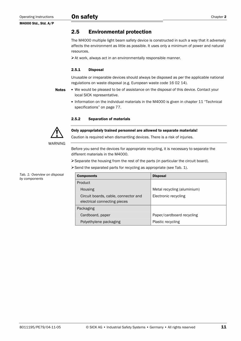
Before you send the devices for appropriate recycling, it is necessary to separate thedifferent materials in the M4000.
Separate the housing from the rest of the parts (in particular the circuit board).
Send the separated parts for recycling as appropriate (see Tab. 1).
Components Disposal
Product
Housing Metal recycling (aluminium)
Circuit boards, cable, connector andelectrical connecting pieces
Electronic recycling
Packaging
Cardboard, paper Paper/cardboard recycling
Polyethylene packaging Plastic recycling
Notes
WARNING
Tab. 1: Overview on disposalby components
Chapter 3 Operating Instructions
M4000 Std., Std. A/P
12 © SICK AG • Industrial Safety Systems • Germany • All rights reserved 8011195/PE79/04-11-05
Product description
3 Product descriptionThis chapter provides information on the special features and properties of the M4000multiple light beam safety device. It describes the construction and the operating principleof the device.
Please read this chapter before mounting, installing and commissioning the device.
3.1 Special features
Properties of all devices described in these operating instructions
protective operation with either internal or external (realised on the machine) restartinterlock
configuration buttons
external device monitoring (EDM)
beam coding
configurable application diagnostic output (ADO)
status display with 7segment display
integrated interface for ASInterface Safety at Work (optional)
reset, connection for the reset button either in the control cabinet or directly to thedevice (optional)
end cap with integrated LED (optional)
M4000 Standard
2, 3 or 4 beams
scanning range up to 70 m
integrated laser alignment aid (optional)
M4000 Standard A/P
less wiring costs: Only one device needs to be connected electrically.
quick and straightforward alignment in conjunction with the M4000 Passive (deflectorunit)
2 beams, scanning range to 7.5 m (M4000 Passive with mirror deflection)
2 or 4 beams, scanning range to 4.5 m (M4000 Passive with fibre-optic deflection)
3.2 Operating principle of the device
3.2.1 The principle of the multiple light beam safety device
The M4000 multiple light beam safety device secures the access to a hazardous area andsignals the entry of objects as soon as a light beam is interrupted. The machine or plantcontroller that evaluates this message must then bring the dangerous movement to a halt.You can secure two sides of a hazardous area by using a deflector mirror, with twodeflector mirrors you can secure three sides (see section 3.3.2 “Access protection onseveral sides with the aid of deflector mirrors” on page 16ff.).

Operating Instructions Chapter 3
M4000 Std., Std. A/P
8011195/PE79/04-11-05 © SICK AG • Industrial Safety Systems • Germany • All rights reserved 13
Product description
3.2.2 Device components
Principles of operation
The M4000 multiple light beam safety device consists of a sender unit and a receiver unit.A distinction should be made between active/active systems and active/passive systems:
On the active/active system, sender unit and receiver unit are in separate housings, thesender and the receiver. The light beam is emitted from the sender and is incident to thereceiver.
Fig. 1: Components of theM4000 Standard
Fig. 2: Components of theM4000 Standard A/P
M4000 Standard
Beam diameter(23 mm)
Beam separation
Dimension of the light path between senderand receiver
M4000 Standard A/P
M4000 Standard A/P
M4000 Passive (deflector unit)
Dimension of the light path betweenM4000 Standard A/P and M4000 Passive(deflector unit)
Beam separation

Chapter 3 Operating Instructions
M4000 Std., Std. A/P
14 © SICK AG • Industrial Safety Systems • Germany • All rights reserved 8011195/PE79/04-11-05
Product description
On the active/passive system, sender unit and receiver unit are in a common housing(M4000 Standard A/P). The light beam is emitted from the sender unit and is deflectedby the deflector unit M4000 Passive (mirror deflection or fibre-optic deflection) by 180°back to the receiver unit (see Fig. 2). As a passive element, the deflector unit does notrequire any electrical connections.
For the exact number and distance of beams, please see chapter 11.3 “Dimensionaldrawings” on page 81ff.
The dimension of the light path between sender and receiver (or between M4000Standard A/P and M4000 Passive) must not exceed the maximum permissible scanningrange (see “Technical specifications” on page 74ff.).
On active/active systems, sender unit and receiver unit synchronise automatically byoptical means. An electrical connection between both components is not required.
The M4000 is modular in structure. All optical and electronic components and assembliesare housed in a slim and torsionally rigid housing.
M4000 Standard
The M4000 Standard multiple light beam safety device is available with 2, 3 or 4 beams.Other configurations with up to 12 beams are possible on request. The maximum scanningrange (dimension of the light path between sender and receiver) is 70 m.
M4000 Standard A/P
The M4000 Standard A/P is available with 2 or 4 beams. The maximum scanning range(dimension of the light path between M4000 Standard A/P and M4000 Passive) is depen-dent on the number of beams as well as the M4000 Passive used and is max. 7.5 m.

Operating Instructions Chapter 3
M4000 Std., Std. A/P
8011195/PE79/04-11-05 © SICK AG • Industrial Safety Systems • Germany • All rights reserved 15
Product description
3.3 Application examples
3.3.1 Access protection
The M4000 multiple light beam safety device operates correctly as a protective device onlyif the following conditions are met:
The control of the machine must be electrical.
It must be possible to achieve a safe state on the machine at any time.
Sender and receiver must be mounted in a way that objects penetrating the hazardousarea are safely identified by the M4000.
The reset button must be fitted outside the hazardous area such that it cannot beoperated by a person working inside the hazardous area. When operating the resetbutton, the operator must have full visual command of the hazardous area.
The statutory and local rules and regulations must be observed when installing andusing the device.
Fig. 3: Access protection witha M4000 Standard multiplelight beam safety device
Fig. 4: Access protection witha M4000 Standard A/Pmultiple light beam safetydevice

Chapter 3 Operating Instructions
M4000 Std., Std. A/P
16 © SICK AG • Industrial Safety Systems • Germany • All rights reserved 8011195/PE79/04-11-05
Product description
3.3.2 Access protection on several sides with the aid of deflector mirrors
You can secure two sides of a hazardous area by using a deflector mirror (see Fig. 5), withtwo deflector mirrors you can secure three sides (see Fig. 6).
Fig. 5: Access protection witha M4000 Standard multiplelight beam safety device andone deflector mirror
Fig. 6: Access protection witha M4000 Standard multiplelight beam safety device andtwo deflector mirrors
Fig. 7: Access protection withan M4000 Standard A/Pmultiple light beam safetydevice and one deflectormirror
Operating Instructions Chapter 3
M4000 Std., Std. A/P
8011195/PE79/04-11-05 © SICK AG • Industrial Safety Systems • Germany • All rights reserved 17
Product description
The formation of droplets of heavy contamination can be detrimental to the reflectionbehaviour. Take the necessary organisational measures to avoid the formation ofdroplets on the deflector mirrors. The deflector mirrors are available as accessories (seepage 95f.).
Deflector mirrors reduce the effective scanning range. The effective scanning rangedepends on the number of deflector mirrors in the light path (see chapter 4.4 “Scanningrange” on page 24ff).
You can extend the M4000 Standard A/P multiple light beam safety device with amaximum of one deflector mirror.
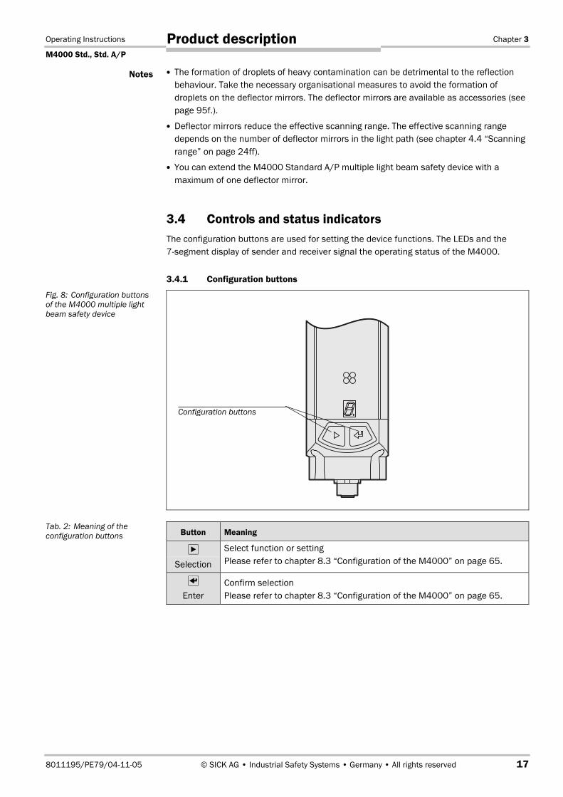
3.4 Controls and status indicatorsThe configuration buttons are used for setting the device functions. The LEDs and the7segment display of sender and receiver signal the operating status of the M4000.
3.4.1 Configuration buttons
Button Meaning
Selection
Select function or settingPlease refer to chapter 8.3 “Configuration of the M4000” on page 65.
Enter
Confirm selectionPlease refer to chapter 8.3 “Configuration of the M4000” on page 65.
Notes
Fig. 8: Configuration buttonsof the M4000 multiple lightbeam safety device
Tab. 2: Meaning of theconfiguration buttons
Configuration buttons
Chapter 3 Operating Instructions
M4000 Std., Std. A/P
18 © SICK AG • Industrial Safety Systems • Germany • All rights reserved 8011195/PE79/04-11-05
Product description
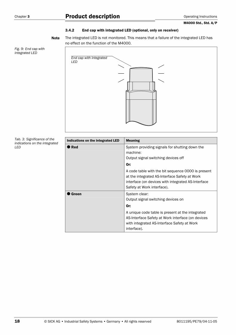
3.4.2 End cap with integrated LED (optional, only on receiver)
The integrated LED is not monitored. This means that a failure of the integrated LED hasno effect on the function of the M4000.
Indications on the integrated LED Meaning
Red System providing signals for shutting down themachine:Output signal switching devices off
Or:
A code table with the bit sequence 0000 is presentat the integrated ASInterface Safety at Workinterface (on devices with integrated ASInterfaceSafety at Work interface).
Green System clear:Output signal switching devices on
Or:
A unique code table is present at the integratedASInterface Safety at Work interface (on deviceswith integrated ASInterface Safety at Workinterface).
Note
Fig. 9: End cap withintegrated LED
Tab. 3: Significance of theindications on the integratedLED
End cap with integratedLED

Operating Instructions Chapter 3
M4000 Std., Std. A/P
8011195/PE79/04-11-05 © SICK AG • Industrial Safety Systems • Germany • All rights reserved 19
Product description
3.4.3 Status indicators of the sender
Display Meaning
Yellow Supply voltage o.k.
System error. Disconnect the supply voltage to the M4000 for at least3 seconds. If the problem persists, replace the unit.
The device is in the test mode.
Non-coded operation (only after switching on)
Operation with code 1 (only after switching on)
Operation with code 2 (only after switching on)
Otherdisplays
All other displays are error messages. Please refer to chapter 10 “Faultdiagnosis” on page 70.
Fig. 10: Status indicators ofthe sender
Tab. 4: Meaning of the statusindicators of the sender
Yellow
7segment display
Chapter 3 Operating Instructions
M4000 Std., Std. A/P
20 © SICK AG • Industrial Safety Systems • Germany • All rights reserved 8011195/PE79/04-11-05
Product description
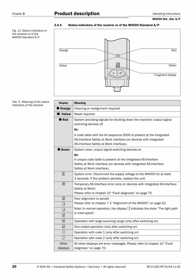
3.4.4 Status indicators of the receiver or of the M4000 Standard A/P
Display Meaning
Orange Cleaning or realignment required
Yellow Reset required
Red System providing signals for shutting down the machine: output signalswitching devices off
Or:
A code table with the bit sequence 0000 is present at the integratedASInterface Safety at Work interface (on devices with integratedASInterface Safety at Work interface).
Green System clear: output signal switching devices on
Or:A unique code table is present at the integrated ASInterfaceSafety at Work interface (on devices with integrated ASInterfaceSafety at Work interface).
System error. Disconnect the supply voltage to the M4000 for at least3 seconds. If the problem persists, replace the unit.
Temporary ASInterface error (only on devices with integrated ASInterfaceSafety at Work)Please refer to chapter 10 “Fault diagnosis” on page 70.
Poor alignment to senderPlease refer to chapter 7.3 “Alignment of the M4000” on page 52.
Note: In normal operation, the display indicates the state “The light pathis interrupted”.
Operation with large scanning range (only after switching on)
Non-coded operation (only after switching on)
Operation with code 1 (only after switching on)
Operation with code 2 (only after switching on)
Otherdisplays
All other displays are error messages. Please refer to chapter 10 “Faultdiagnosis” on page 70.
Fig. 11: Status indicators ofthe receiver or of theM4000 Standard A/P
Tab. 5: Meaning of the statusindicators of the receiver
Orange Red
Yellow Green
7segment display
Operating Instructions Chapter 9
M4000 Std., Std. A/P
8011195/PE79/04-11-05 © SICK AG • Industrial Safety Systems • Germany • All rights reserved 69
Care and maintenance
9 Care and maintenanceThe M4000 multiple light beam safety device is maintenance-free. The front screen of theM4000 multiple light beam safety device should be regularly cleaned and also ifcontaminated.
Do not use aggressive detergents.
Do not use abrasive cleaning agents.
Static charges cause dust particles to be attracted to the front screen. You can preventthis effect by using the antistatic plastic cleaner (SICK Part No. 5600006) and the SICKlens cloth (SICK Part No. 4003353).
How to clean the front screen:
Use a clean and soft brush to remove dust from the front screen.
Now wipe the front screen with a clean and damp cloth.
After cleaning, check the position of sender and receiver to ensure that the protectivedevice cannot be bypassed (reaching over, under or standing behind).
Verify the effectiveness of the protective device as described in chapter 7.4 “Test notes”on page 61.
Note
Note
Chapter 10 Operating Instructions
M4000 Std., Std. A/P
70 © SICK AG • Industrial Safety Systems • Germany • All rights reserved 8011195/PE79/04-11-05
Fault diagnosis
10 Fault diagnosisThis chapter describes how to identify and remedy errors and malfunctions during theoperation of the M4000 multiple light beam safety device.
10.1 In the event of faults or errors
Cease operation if the cause of the malfunction has not been clearly identified!
Stop the machine if you cannot clearly identify or allocate the error and if you cannot safelyremedy the malfunction.
Complete function test after rectification of fault!
After rectifying a fault, perform a complete function test as per section 7.4 “Test notes”.
The lockout status
In case of certain faults or an erroneous configuration, the system can go into the lockoutstatus. The 7segment display on the multiple light beam safety device then indicates ora defined error message (see Tab. 27).
First check whether the lockout status is still present after switching off and on theM4000 (e.g. by disconnecting the system plug and re-connecting).
To place the device back in operation:
Rectify the cause of the fault as per Tab. 27.
Switch the power supply for the M4000 off and on again (e.g. by unplugging the systemplug and reinserting it).
The lockout status has the highest priority above all other indications on the 7segmentdisplay.
10.2 SICK supportIf you cannot remedy an error with the help of the information provided in this chapter,please contact your local SICK representative.
WARNING
Note

Operating Instructions Chapter 10
M4000 Std., Std. A/P
8011195/PE79/04-11-05 © SICK AG • Industrial Safety Systems • Germany • All rights reserved 71
Fault diagnosis
10.3 Error displays of the LEDsThis chapter explains the meaning of the error displays of the LEDs and how to respond.Please refer to chapter 3.4 “Controls and status indicators” on page 17 for a description.
Display Possible cause Remedying the error
Sender
Yellow LED fails to lightup
No operatingvoltage, or voltagetoo low
Check the voltage supply andactivate, if necessary.
Receiver or M4000 Standard A/P
Orange LED illuminated Received signal isweak
Check the alignment of senderand receiver or of the M4000Standard A/P and the M4000Passive.
Check the front screen (dirt) andclean, if necessary.
Yellow LED flashing Reset required Press the reset button.
Red and Green
Neither the rednor the greenLED lights up
No operatingvoltage, or voltagetoo low
Check the voltage supply andactivate, if necessary.
10.4 Error displays of the 7segment displayThis chapter explains the meaning of the error displays of the 7segment display and howto respond to the messages. Please refer to chapter 3.4 “Controls and status indicators”on page 17 for a description of the 7segment display.
Display Possible cause Remedying the error
, , or
Inadequate alignment(in alignment mode)
Re-align sender and receiver (see page 51).
The display goes off after 2 minutes.
The light path isinterrupted(in normal operation)
Rectify the cause of the interruption in the lightpath.
Waiting forconfiguration orconfiguration notcompleted
The display goes off automatically once theconfiguration has been started.
When the display appears when the configu-ration mode is left:
Switch the device off and on and repeat theconfiguration of the system (see chapter 8 onpage 64).
or
EDM error(see also page 26)
Check the contactors and their wiring, eliminateany wiring errors, if necessary.
If is displayed, switch the device off and backon again.
Tab. 26: Error displays of theLEDs
Tab. 27: Error displays of the7segment display
Chapter 10 Operating Instructions
M4000 Std., Std. A/P
72 © SICK AG • Industrial Safety Systems • Germany • All rights reserved 8011195/PE79/04-11-05
Fault diagnosis
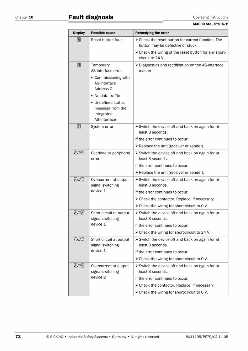
Display Possible cause Remedying the error
Reset button fault Check the reset button for correct function. Thebutton may be defective or stuck.
Check the wiring of the reset button for any short-circuit to 24 V.
TemporaryASInterface error
Commissioning withAS-InterfaceAddress 0
No data traffic
Undefined statusmessage from theintegratedASInterface
Diagnostics and rectification on the ASInterfacemaster
System error Switch the device off and back on again for atleast 3 seconds.
If the error continues to occur:
Replace the unit (receiver or sender).
Overload or peripheralerror
Switch the device off and back on again for atleast 3 seconds.
If the error continues to occur:
Replace the unit (receiver or sender).
Overcurrent at outputsignal switchingdevice 1
Switch the device off and back on again for atleast 3 seconds.
If the error continues to occur:
Check the contactor. Replace, if necessary.
Check the wiring for short-circuit to 0 V.
Short-circuit at outputsignal switchingdevice 1
Switch the device off and back on again for atleast 3 seconds.
If the error continues to occur:
Check the wiring for short-circuit to 24 V.
Short-circuit at outputsignal switchingdevice 1
Switch the device off and back on again for atleast 3 seconds.
If the error continues to occur:
Check the wiring for short-circuit to 0 V.
Overcurrent at outputsignal switchingdevice 2
Switch the device off and back on again for atleast 3 seconds.
If the error continues to occur:
Check the contactor. Replace, if necessary.
Check the wiring for short-circuit to 0 V.

Operating Instructions Chapter 10
M4000 Std., Std. A/P
8011195/PE79/04-11-05 © SICK AG • Industrial Safety Systems • Germany • All rights reserved 73
Fault diagnosis
Display Possible cause Remedying the error
Short-circuit at outputsignal switchingdevice 2
Switch the device off and back on again for atleast 3 seconds.
If the error continues to occur:
Check the wiring for short-circuit to 24 V.
Short-circuit at outputsignal switchingdevice 2
Switch the device off and back on again for atleast 3 seconds.
If the error continues to occur:
Check the wiring for short-circuit to 0 V.
Short-circuit betweenoutput signal switchingdevice 1 and 2
Switch the device off and back on again for atleast 3 seconds.
If the error continues to occur:
Check the wiring and rectify the error.
Invalid configuration ofthe EDM
Switch the device off and back on again for atleast 3 seconds.
If the error continues to occur:
Check whether the machine-side EDM isconnected but not activated in the configuration.
Unknown senderdetected
Switch the device off and back on again for atleast 3 seconds.
If the error continues to occur:
Check the distance from reflective surfaces(page 33) or from other multiple light beamsafety devices.
If necessary, re-configure the device with anotherbeam coding (page 23) or install non-reflectivepartitions.
Supply voltage error Switch the device off and back on again for atleast 3 seconds.
If the error continues to occur:
Check whether the power supply complies withthe specification (see page 74).
Check whether the cable lengths comply with thespecification (see page 74, the cable lengthsmust not be exceeded).

Chapter 11 Operating Instructions
M4000 Std., Std. A/P
74 © SICK AG • Industrial Safety Systems • Germany • All rights reserved 8011195/PE79/04-11-05
Technical specifications
11 Technical specifications
11.1 Data sheet
11.1.1 M4000 Standard and M4000 Standard A/P
Minimum Typical Maximum
General system data
Number of beams, type-dependent
M4000 Standard 2 12
M4000 Standard A/P 2 4
Beam separation, type-dependent
M4000 Standard 120 mm 600 mm
M4000 Standard A/P 500 mm and300 mm
Scanning range, configurable
M4000 Standard
Low scanning range 0.5 m 20 m
High scanning range 15 m 70 m
Scanning range2)
M4000 Standard A/P
With mirror deflection 0.5 m 7.5 m
With fibre-optic deflection 0.5 m 4.5 m
Beam diameter 23 mm
Protection class(EN 50178:1998)3)
III
Enclosure rating (IEC 60529) IP 65Supply voltage VS at device4) 19.2 V 24 V 28.8 VResidual ripple5) ±10%Synchronisation6) Optical, without separate synchronisation
Type according to IEC 61496 Type 4
Power-up delay of sender andreceiver before ready
10 s
2) The scanning range of the M4000 Standard A/P device must be configured to suit the deflection used (seesection 4.4.2 “Scanning range of the M4000 Standard A/P” on page 25).
3) Safety extra-low voltage SELV/PELV.4) The external voltage supply must be capable of buffering brief mains voltage failures of 20 ms as specified in
EN 60204-1. Suitable power supplies are available as accessories from SICK (Siemens type series 6 EP 1).5) Within the limits of VS.6) Only with Active/Active systems.
Tab. 28: Data sheetM4000 Standard andM4000 Standard A/P
Operating Instructions Chapter 11
M4000 Std., Std. A/P
8011195/PE79/04-11-05 © SICK AG • Industrial Safety Systems • Germany • All rights reserved 75
Technical specifications
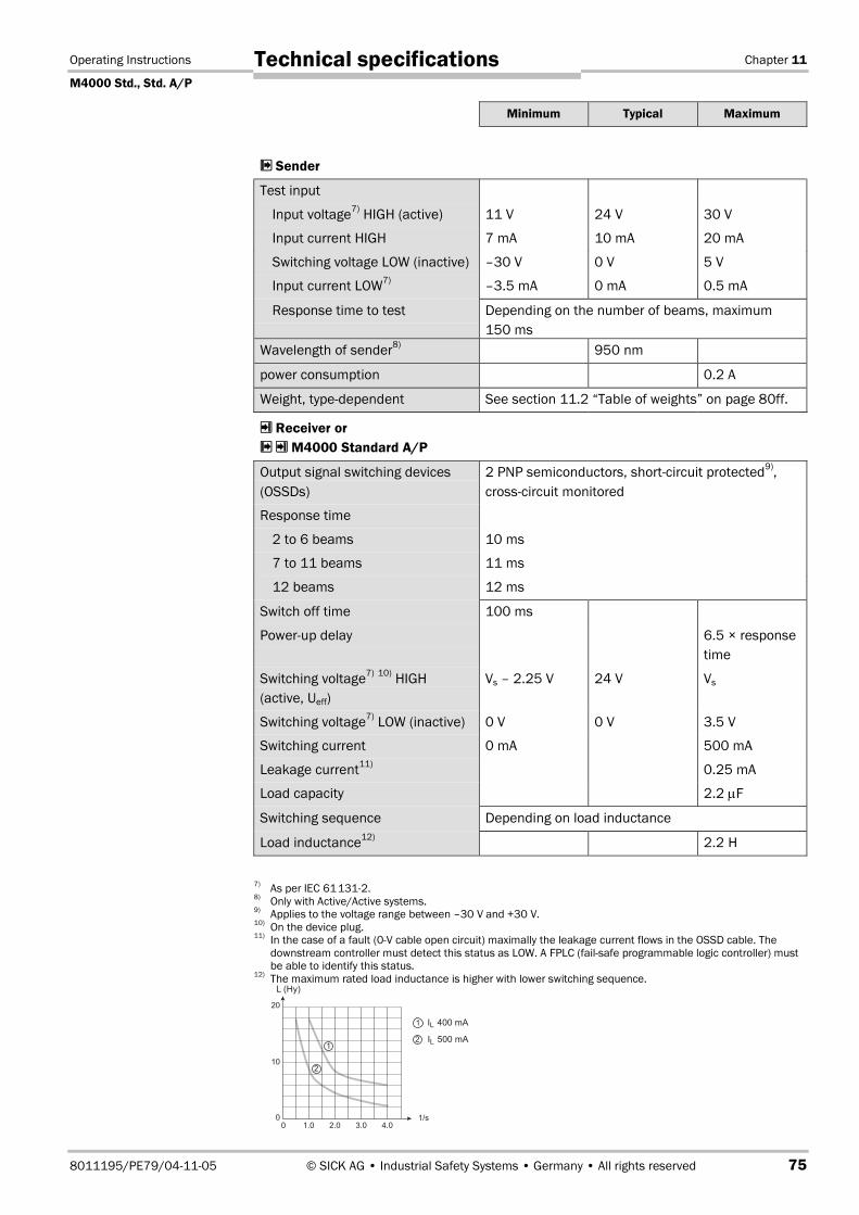
Minimum Typical Maximum
Sender
Test input
Input voltage7) HIGH (active) 11 V 24 V 30 V
Input current HIGH 7 mA 10 mA 20 mA
Switching voltage LOW (inactive) –30 V 0 V 5 V
Input current LOW7) –3.5 mA 0 mA 0.5 mA
Response time to test Depending on the number of beams, maximum150 ms
Wavelength of sender8) 950 nm
power consumption 0.2 A
Weight, type-dependent See section 11.2 “Table of weights” on page 80ff.
Receiver orM4000 Standard A/P
Output signal switching devices(OSSDs)
2 PNP semiconductors, short-circuit protected9),cross-circuit monitored
Response time
2 to 6 beams 10 ms
7 to 11 beams 11 ms
12 beams 12 ms
Switch off time 100 ms
Power-up delay 6.5 × responsetime
Switching voltage7) 10) HIGH(active, Ueff)
Vs – 2.25 V 24 V Vs
Switching voltage7) LOW (inactive) 0 V 0 V 3.5 V
Switching current 0 mA 500 mA
Leakage current11) 0.25 mA
Load capacity 2.2 µF
Switching sequence Depending on load inductance
Load inductance12) 2.2 H
7) As per IEC 61131-2.8) Only with Active/Active systems.9) Applies to the voltage range between –30 V and +30 V.10) On the device plug.11) In the case of a fault (0-V cable open circuit) maximally the leakage current flows in the OSSD cable. The
downstream controller must detect this status as LOW. A FPLC (fail-safe programmable logic controller) mustbe able to identify this status.
12) The maximum rated load inductance is higher with lower switching sequence.
Chapter 11 Operating Instructions
M4000 Std., Std. A/P
76 © SICK AG • Industrial Safety Systems • Germany • All rights reserved 8011195/PE79/04-11-05
Technical specifications
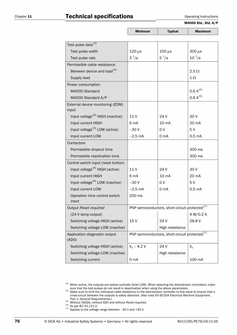
Minimum Typical Maximum
Test pulse data13)
Test pulse width 120 µs 150 µs 300 µs
Test pulse rate 3 1/s 5 1/s 10 1/s
Permissible cable resistance
Between device and load14) 2.5 Ω
Supply lead 1 Ω
Power consumption
M4000 Standard 0.6 A15)
M4000 Standard A/P 0.6 A15)
External device monitoring (EDM)input
Input voltage16) HIGH (inactive) 11 V 24 V 30 V
Input current HIGH 6 mA 10 mA 20 mA
Input voltage16) LOW (active) –30 V 0 V 5 V
Input current LOW –2.5 mA 0 mA 0.5 mA
Contactors
Permissible dropout time 300 ms
Permissible reactivation time 300 ms
Control switch input (reset button)
Input voltage16) HIGH (active) 11 V 24 V 30 V
Input current HIGH 6 mA 10 mA 20 mA
Input voltage16) LOW (inactive) –30 V 0 V 5 V
Input current LOW –2.5 mA 0 mA 0.5 mA
Operation time control switchinput
200 ms
Output Reset required PNP semiconductors, short-circuit protected17)
(24 V lamp output) 4 W/0.2 A
Switching voltage HIGH (active) 15 V 24 V 28.8 V
Switching voltage LOW (inactive) High resistance
Application diagnostic output(ADO)
PNP semiconductors, short-circuit protected17)
Switching voltage HIGH (active) Vs – 4.2 V 24 V Vs
Switching voltage LOW (inactive) High resistance
Switching current 0 mA 100 mA
13) When active, the outputs are tested cyclically (brief LOW). When selecting the downstream controllers, makesure that the test pulses do not result in deactivation when using the above parameters.
14) Make sure to limit the individual cable resistance to the downstream controller to this value to ensure that across-circuit between the outputs is safely detected. (Also note EN 60204 Electrical Machine Equipment,Part 1: General Requirements.)
15) Without OSSDs, without ADO and without Reset required.16) As per IEC 61131-2.17) Applies to the voltage range between –30 V and +30 V.