M170 M89 M60 M91 M130 M96 M201 M168 M52 NEXT yDNA Haplogroup I.

08/01
OWNER’S MANUAL
KEEP THIS MANUAL
The technical specifications and the wiring diagrams contained in this owner’s manual are valid only for the model that has the part number indicated below.
M 130 - M 170
M 130: ALW-M120500381
M 170: ALW-M120500382
Air Liquide Welding is a trademark of L’Air Liquide S.A.

TABLE OF CONTENTS
1 SAFETY PRECAUTIONS - READ BEFORE USING1.1 INSTALLATION OF EQUIPMENT . . . . . . . . . . . . . . . . . . . . . . . . . . . . . . . . . . . . . . . . . . . .31.2 PERSONAL PROTECTION . . . . . . . . . . . . . . . . . . . . . . . . . . . . . . . . . . . . . . . . . . . . . . . . .31.3 FIRE AND EXPLOSION PREVENTION . . . . . . . . . . . . . . . . . . . . . . . . . . . . . . . . . . . . . . . .41.4 METAL FUME HAZARDS . . . . . . . . . . . . . . . . . . . . . . . . . . . . . . . . . . . . . . . . . . . . . . . . . .41.5 TRANSPORTING THE POWER SOURCE . . . . . . . . . . . . . . . . . . . . . . . . . . . . . . . . . . . . . .41.6 MAGNETIC FIELDS CAN AFFECT PACEMAKERS . . . . . . . . . . . . . . . . . . . . . . . . . . . . . . .41.7 H.F. RADIATION CAN CAUSE INJURY . . . . . . . . . . . . . . . . . . . . . . . . . . . . . . . . . . . . . . . . .51.8 ARC WELDING CAN CAUSE INTERFERENCE . . . . . . . . . . . . . . . . . . . . . . . . . . . . . . . . . .51.9 WELDING AND THE EFFECTS OF LOW FREQUENCY AND MAGNETIC FIELDS . . . . . . .51.10 PRINCIPAL SAFETY STANDARDS . . . . . . . . . . . . . . . . . . . . . . . . . . . . . . . . . . . . . . . . . . .5
2 SPECIFICATIONS AND DESCRIPTION 2.1 SPECIFICATIONS . . . . . . . . . . . . . . . . . . . . . . . . . . . . . . . . . . . . . . . . . . . . . . . . . . . . . . . .72.2 DESCRIPTION . . . . . . . . . . . . . . . . . . . . . . . . . . . . . . . . . . . . . . . . . . . . . . . . . . . . . . . . . . .72.3 COMES COMPLETE WITH . . . . . . . . . . . . . . . . . . . . . . . . . . . . . . . . . . . . . . . . . . . . . . . . .72.4 DUTY CYCLE AND OVERHEATING . . . . . . . . . . . . . . . . . . . . . . . . . . . . . . . . . . . . . . . . . . .82.5 VOLT-AMPERE CURVES . . . . . . . . . . . . . . . . . . . . . . . . . . . . . . . . . . . . . . . . . . . . . . . . . . .9
3 INSTALLATION3.1 CONNECTING THE EQUIPMENT TO THE MAIN SUPPLY . . . . . . . . . . . . . . . . . . . . . . . .103.2 SELECTING A LOCATION . . . . . . . . . . . . . . . . . . . . . . . . . . . . . . . . . . . . . . . . . . . . . . . . .103.3 CHANGING POLARITY . . . . . . . . . . . . . . . . . . . . . . . . . . . . . . . . . . . . . . . . . . . . . . . . . . .103.4 INSTALLING WELDING GUN . . . . . . . . . . . . . . . . . . . . . . . . . . . . . . . . . . . . . . . . . . . . . . .103.5 INSTALLING WIRE SPOOL AND ADJUSTING HUB TENSION . . . . . . . . . . . . . . . . . . . . .123.6 INSTALLING THE WIRE INTO THE WELDING GUN . . . . . . . . . . . . . . . . . . . . . . . . . . . . . .123.7 INSTALLING SG 185 SPOOL GUN . . . . . . . . . . . . . . . . . . . . . . . . . . . . . . . . . . . . . . . . . .13
4 OPERATION 4.1 FRONT PANEL CONTROLS . . . . . . . . . . . . . . . . . . . . . . . . . . . . . . . . . . . . . . . . . . . . . . . .144.2 BACK PANEL CONTROLS . . . . . . . . . . . . . . . . . . . . . . . . . . . . . . . . . . . . . . . . . . . . . . . . .14
5 MAINTENANCE AND TROUBLESHOOTING5.1 TORCH MAINTENANCE . . . . . . . . . . . . . . . . . . . . . . . . . . . . . . . . . . . . . . . . . . . . . . . . . .145.2 REPLACING GUN LINER . . . . . . . . . . . . . . . . . . . . . . . . . . . . . . . . . . . . . . . . . . . . . . . . . .155.3 TROUBLESHOOTING . . . . . . . . . . . . . . . . . . . . . . . . . . . . . . . . . . . . . . . . . . . . . . . . . . . .15
6 M 130 ELECTRICAL DIAGRAM . . . . . . . . . . . . . . . . . . . . . . . . . . . . . . . . . . . . . . . . . . . . .16
7 M 170 ELECTRICAL DIAGRAM . . . . . . . . . . . . . . . . . . . . . . . . . . . . . . . . . . . . . . . . . . . . .17
8 M 130 SPARE PARTS LIST . . . . . . . . . . . . . . . . . . . . . . . . . . . . . . . . . . . . . . . . . . . . . . . .18
9 M 170 SPARE PARTS LIST . . . . . . . . . . . . . . . . . . . . . . . . . . . . . . . . . . . . . . . . . . . . . . . . .20
10 M 130 – M 170 COMMON SPARE PARTS LIST . . . . . . . . . . . . . . . . . . . . . . . . . . . . . . .22
11 MG 140 SPARE PARTS LIST . . . . . . . . . . . . . . . . . . . . . . . . . . . . . . . . . . . . . . . . . . . . . . .23
The use of welding equipment can causeinjury to the operator. The reading and understand-ing of the safety standards mentioned below is com-pulsory prior to connecting, preparing, using ortransporting welding equipment.
1.1 INSTALLATION OF EQUIPMENT
1. Installation and maintenance of equipmentmust be performed in compliance with localsafety standards.
2. Frequently inspect the welder plug,receptacle and wiring. If damaged, replaceimmediately with approved electrical connec-tions and adequately sized wiring.
3. Connect the welding ground as near as possi-ble to the operating area.
4. Do not pass welding equipment cables throughor near lifting chains, crane cables or any elec-trical lines.
5. If earth grounding of the workpiece is required,ground it directly with a separate cable.
6. Do not touch the electrode if you are in contactwith the work, ground or another electrode froma different welding machine.
7. Use only well-maintained equipment. Repair orreplace damaged parts immediately. Maintainwelding equipment according to owner’s manu-al.
8. Never use welding equipment near water. Do notspray water or other liquids on the welding equipment.
9. Avoid direct contact between wet garments andmetal parts that are electrically charged.
10.Always wear gloves and rubber-soled shoeswhen working in wet areas or standing on metalsurfaces.
11.Always turn off welding equipment that is notbeing used. Do not leave welding equipmentunattended.
Significant DC voltage exists after removal ofinput power or inverters.• Always discharge input capacitors before touch-
ing any parts. Service work should be complet-ed by qualified personnel only.
1.2 PERSONAL PROTECTION
1. Welding operations produce radiation, noise,heat and noxious fumes. Suitable safety pre-cautions must be taken to minimize the risk.
2. Wear fire resistant work gloves, longsleeve shirts, pants, safety shoes, cap andwelding helmet to protect the skin from radia-tion and metal sparks.
3. Always wear ear protection.
4. Always wear eye protection with side shields.
5. Position a fire resistant screen around the weld-ing area to protect bystanders from radiation,sparks and slag.
3
1. SAFETY PRECAUTIONS - READ BEFORE USING
WARNING
Read and understand this entire Owner’s Manual before installing, operating or servicing this equipment. Whilethe information contained in this Owner’s manual represents our best judgment, Air Liquide assumes no lia-bility for its use.
Reproduction of this work, in whole or part, without written permission of the publisher is prohibited.
All rights reserved.
The publisher does not assume and hereby disclaims any liability to any party for any loss or damage causedby any error or omission in the Air Liquide M 130 – M 170 Owner’s Manual, whether such error results from neg-ligence, accident or any other causes.

6. Compressed gas cylindersare potentially dangerous. Consult the supplierfor correct handling procedures. Always protectcompressed gas cylinders from the sun’s rays,flames and sudden temperature changes.
1.3 FIRE AND EXPLOSION PREVENTION
Hot slag and sparks cancause fire. The risk of fire and explosion canbe minimized by removing all flammable mate-rial from the welding area.
1. Always perform welding operation with caution.Containers and tubes that have been emptiedand thoroughly cleaned still represent a poten-tial hazard.
2. Never perform welding operations or cut aclosed container or pipe.
3. Never perform welding operations on open con-tainers or pipes that may have been contami-nated with substances that could explode orreact when exposed to heat or humidity.
4. As a preventative measure, keep fire extin-guishers near the welding operation.
1.4 METAL FUME HAZARDS
Welding fumes and gases may behazardous if inhaled.
1. Install a ventilation system in the welding area.
2. Use a forced air system when welding lead,beryllium, cadmium, zinc, zinc-coated or paint-ed material. Always wear a protective mask.
3. If the ventilation system is inadequate, use anair respirator.
4. Beware of gas leaks. Shielding gases such asargon are heavier than air and when used insmall spaces, will replace the air.
5. In the event that a welding operation occurs ina confined place, the operator should beaccompanied by another person.
6. Always keep gas cylinders in a well-ventilatedarea. Close the main gas valve when cylinderis not in use.
7. Do not perform welding operations near chlori-nated hydrocarbon vapors produced bydegreasing or painting. The heat generated byarc rays can react to form phosgene, a highlytoxic gas.
8. Irritation of the eyes, nose and throat are symp-toms of inadequate ventilation. Take immediatesteps to improve ventilation. Do not continuewelding if symptoms persist.
1.5 TRANSPORTING THE POWERSOURCE
The welding machine may be carried by thehandle.
1. Always disconnect the power source andaccessories from the main supply before liftingor handling the welding equipment.
2. Do not drag, pull or lift welding equipment bythe weld cables.
1.6 MAGNETIC FIELDS CAN AFFECTPACEMAKERS
1. Keep pacemaker wearers away fromwelding operations.
2. Pacemaker wearers should consult with aphysician prior to being exposed to any weldingor cutting operation.
4

5
1.7 H.F. RADIATION CAN CAUSE INJURY
1. High frequency (HF) emissions caninterfere with radio navigation, safety devices,computers and communication equipment.
2. Installation of welding equipment should beperformed by a qualified electrician.
3. The operator is responsible for having a quali-fied electrician correct any interference problemresulting from the welding equipment installa-tion.
4. If notified by the FCC about interference, stopusing the welding equipment immediately.
5. Have the welding equipment installationchecked and maintained on a regular basis.
6. Keep high-frequency source doors and panelstightly shut. Keep spark gaps at the correct set-ting and use grounding to minimize the possi-bility of interference.
1.8 ARC WELDING CAN CAUSE INTER-FERENCE
1. Electromagnetic energy can interferewith sensitive electronic equipment such ascomputers and computer-driven equipment likerobots.
2. Be sure that all equipment in the welding areais electro-magnetically compatible.
3. To reduce possible interference, keep weldcables as short as possible, close together anddown low.
4. Locate welding operations at least 100 meters(350 feet) away from any sensitive electronicequipment.
5. Be sure welding equipment is installed andgrounded according to this manual.
6. If interference still occurs, the operator musttake extra measures such as moving the weld-ing machine, using shielded cables, using linefilters or shielding the work area.
1.9 WELDING AND THE EFFECTS OF LOWFREQUENCY AND MAGNETIC FIELDS
As welding current flows through welding cables, itcan cause electromagnetic fields. To reduce mag-netic fields, use the following procedures:
1 Keep cables close together by twisting or tapingthem.
2. Arrange cables to one side and away from theoperator.
3. Do not coil or drape coils around operatorsbody.
4. Keep welding power source and cables as faraway from the operator as practically possible.
5. Connect work clamp to workpiece as close tothe weld as possible.
1.10 PRINCIPAL SAFETY STANDARDS
Safety in Welding and Cutting, ANSI StandardZ49.1 from the American Welding Society, 550N.W. Lejeune Rd., Miami, FL 33126.
Safety and Health Standards, OSHA 29 CFR1910, from the Superintendent of Documents,U.S. Government Printing Office, Washington,D.C. 20402.
Recommended Safe Practices for the Preparationfor Welding and Cutting of Containers That HaveHeld Hazardous Substances, American WeldingSociety Standard AWS F4.1, from the AmericanWelding Society, 550 N.W. Lejeune Rd., Miami, FL33126.
National Electrical Code, NFPA Standard 70, fromthe National Fire Protection Association,Batterymarch Park, Quincy, MA 02269.
Safe Handling of Compressed Gases in Cylinders,CGA Pamphlet P-1, from the Compressed GasAssociation, 1235 Jefferson Davis Highway, Suite501, Arlington, VA 22202.
Code for Safety in Welding and Cutting, CSAStandard W117.2, from the Canadian StandardsAssociation, Standard Sales, 178 RexdaleBoulevard, Rexdale, Ontario M9W 1R3.
Safe Practices For Occupation And EducationalEye And Face Protection, ANSI Standards Z87.1from the American National Standards Institute,1430 Broadway, New York, NY 10018.
Cutting And Welding Processes, NFPA Standards51B, from the National Fire Protection Association,Batterymarch Park, Quincy, MA 02269.

6
EQUIPMENT INSTALLATION AND MAINTENANCE MUST BE PERFORMED INCOMPLIANCE WITH LOCAL SAFETY STANDARDS.
• INSTALLATION AND MAINTENANCE OPERATIONS MUST BE PERFORMED BY QUALIFIED PERSONSONLY.
• BEFORE INSTALLING the power source, check that the power socket satisfies ampere and voltagerequirements (see data table plate). ENSURE that the socket is protected by appropriate fuses and auto-matic switches.
• CONNECT an approved standard plug corresponding to the system socket to the power supply cable.
Electric shock could be fatal
1. Never touch exposed electricalparts.
2. Switch off and disconnect thepower source before installingor opening.
3. Installation may be performedby qualified persons only.
4. Installation procedure mustcomply with national electricitystandards and all other relevantregulations.
Fumes and gases may repre-sent a safety hazard.Fumes and gases generatedduring welding may be danger-ous if inhaled over a long periodof time.
1. Keep clear of fumes.
2. Ventilate welding area or weara breathing mask.
3. Install a natural or forced airventilation system in the workarea.
Use a protective mask with suit-able glass filter (at least NR10)to safeguard eyes.
1. Wear appropriate eye, ear andbody protection equipment.
2. Protect face, ears and neckduring welding operations.Advise other persons in thevicinity to look away and standclear of arc rays and hot metal.
The positioning of weldingequipment on inflammable sur-faces could lead to fire outbreakor explosion.
1. Never position equipment oncombustible or inflammablesurfaces.
2. Do not install equipment in thevicinity of inflammable liquids.
A falling power source or otherequipment may cause seriousinjury to persons or damage toobjects.
1. Always make use of the handleto lift power source (applies toportable models).
2. Use eye bolts and adequate lift-ing equipment to raise thepower source.
WELDING MAY CAUSE FIRES OREXPLOSIONS. Never weld nearinflammable materials.
1. Beware of weld flame. Alwayskeep a fire extinguisher close athand.
2. Never place welding equipmenton inflammable surfaces.
3. Do not weld in closed containers.
4. Let welding equipment andmaterial cool before handlingthem.
Moving parts may cause injury.
1. Keep clear of hazardous areas,such as moving rollers.
2. Keep all doors, panels and covers closed and in place.
Hot areas may cause injury.
Let the power source or otherparts cool before performingany maintenance or servicing.
Welding wire may cause injury.
Do not point the torch towardany part of the body, other per-sons or any type of metal whenunwinding welding wire.

7
2. SPECIFICATIONS AND DESCRIPTION2.1 SPECIFICATIONS
2.2 DESCRIPTION
M 130 is a complete semi-automatic, constantvoltage, DC arc welding machine. This compact,reliable unit, capable of welding material thick-nesses from 0.5 mm (24 gauge) to 4.8 mm (3/16in), is ideal for the home hobbyist, the workshopor auto body repairs. The easy-to-use M 130plugs into any 110-volt receptacle and delivers asuperior, consistent arc. The portable M 130weighs 23 kg (50 lb) and offers excellent perform-ance throughout the entire welding range. Throwon an optional spool gun and you have a conven-ient, immediate solution for all youraluminum welding needs.
M 170 is a complete semi-automatic, constant voltage, DC arc welding machine. This compact, reliable unit,capable of welding material thicknesses from 0.5 mm(24 gauge) to 6.35 mm (1⁄4 in) is ideal for light fabrica-tion, the garage or auto body repairs. The easy-to-useM 170 offers versatility and delivers a superior, consis-tent arc. The portable M 170 weighs 28 kg (62 lb) andoffers excellent performance throughout the entirewelding range. Throw on an optional spool gun and youhave a convenient, immediate solution for all your alu-minum welding needs.
2.3 COMES COMPLETE WITH:
1. 2.4 m (8 ft) input power cord with 5p-15 plug (M 130) or 6p-50 plug (M 170)
2. 3 m (10 ft) MIG gun3. Extra contact tips4. 3 m (10 ft) ground cable with clamp5. 1 lb spool adaptor
1
24
3
5
M 130 M 170
M 170
1

8
2.4 DUTY CYCLE AND OVERHEATING:
Duty cycle is the percentage of 10 minutes that the unit can weld at its rated output without overheating. If theunit overheats, the weld output will stop. To correct this situation, wait fifteen minutes for the unit to cool. Reduceamperage or duty cycle before starting to weld again.
• Exceeding duty cycle can damage unit and void warranty.
DUTY CHART M 130
020406080
100120
10 20 30 40 50 60 70 80 90 100
% DUTY CYCLE
DUTY CHART M 170
020406080
100120140
10 20 25 30 40 50 60 70 80 90 100
% DUTY CYCLE
OU
TP
UT,
AM
PE
RE
SO
UT
PU
T,A
MP
ER
ES
M 130 Duty Cycle
M 170 Duty Cycle

9
0
5
10
15
20
25
30
35
40
0 20 40 60 80 100 120 140 160 180 200 220 240
2.5 VOLT-AMPERE CURVES
Volt-ampere curves show the maximum voltage and amperage output capabilities of the welding power source.Curves of other settings fall under curves shown.
Volts
Volts
Amps
Amps
M 130 Volt-Ampere Curve
M 170 Volt-Ampere Curve

10
3. INSTALLATION
3.1 CONNECTING THE EQUIPMENT TOTHE MAIN SUPPLY
The equipment works within an input range of±10%.
Check to ensure that the power outlet is equippedwith a fuse that is capable of carrying the ampsindicated on the data plate of this unit.
3.2 SELECTING A LOCATION
Special installation may be requiredwhere gasoline or volatile liquids are present(See NEC Article 511 or CEC Section 20). Donot move or operate this equipment where itcould tip over. When selecting a location forthis equipment, ensure that the followingguidelines are followed:
1. Use data plate to determine input powerrequirements.
2. The operator must have unobstructed access toall controls and equipment connections.
3. Do not position equipment in small, closedplaces. Ventilation of the power source isextremely important. Make sure that the louverson the side panels are not obstructed and thatthere is no risk of obstruction during operation.
4. Avoid areas where dust or other objects couldbe sucked into the system.
5. Equipment must not obstruct corridors or workactivities of other personnel.
6. Position the power source securely to avoidfalling or overturning.
7. Understand the risk of falling equipment situat-ed in overhead positions.
3.3 CHANGING POLARITY
TURN OFF WELDER BEFORE MAKINGCONNECTIONS.
(Consult wire data to verify polarity require-ments.)
DCEN (Straight Polarity)
1. Connect the ground cable to the positive recep-tacle inside the unit.
2. Connect the power cable to the negative recep-tacle inside the unit.
DCEP (Reverse Polarity)
1. Connect the ground cable to the negative recep-tacle inside the unit.
2. Connect the power cable to the positive recep-tacle inside the unit.
INSTALLING GAS HOSE AND REGULATOR
1. Install the gas hose on the inlet connectionlocated on the rear of the machine.
2. Install the regulator on the cylinder outlet con-nection located on the top of the compressedgas cylinder.
3. Connect the male gas hose connection to thefemale regulator connection.
3.4 INSTALLING WELDING GUN
TURN OFF WELDER BEFORE MAKINGCONNECTIONS.
Before connecting the torch, ensure that the driverolls, gun liner and contact tip match the diameterof the wire being used.
When installing the welding gun, follow thesequence described below.

11
1
2
3
4
INSTALLING WELDING GUNTURN OFF WELDER BEFORE MAKING CONNECTIONS.
Supplied withmachine

12
3.5 INSTALLING WIRE SPOOL ANDADJUSTING HUB TENSION
1. Install the wire spool (See figure 2)2. To increase tension, adjust the 11/16” nut in a
clockwise direction.3. To decrease tension, adjust the 11/16” nut in a
counter clockwise direction.
3.6 INSTALLING THE WIRE INTO THEWELDING GUN
1. Open the pressure assembly on the wire feed-er.
2. Push wire through guide into gun.3. Close and tighten pressure assembly.4. Remove gun nozzle and contact tip.5. Press the gun trigger until wire comes out of
the welding gun.
Typical Weld Parameter Settings : M 130
Fig. 2
Typical Weld Parameter Settings : M 170
6. Reinstall contact tip and nozzle.7. Feed wire by pressing the gun trigger to check
drive roll pressure.8. Tighten pressure assembly knob enough to pre-
vent slippage.9. Cut off wire and begin welding.

13
3.7 INSTALLING SG 185 SPOOL GUN
1. Lift and position the side panel into an upright position.2. Remove gun inlet cover located on the front panel of the welding machine.3. Insert the SG 185 Spool Gun through the gun inlet.4. Remove the gas hose from the gas inlet on the wire feeder unit (See reference 1 in figure 1).5. Connect the male gas connection (See reference 2 in figure 2) of the spool gun to the gas hose.6. Remove the male trigger connector (See reference 2 in figure 1).7. Connect the male spool gun trigger connector (See reference 1 in figure 2) to the female trigger receptacle.8. Connect the power cable lug (See reference 3 in figure 2) to the positive receptacle inside the unit
(See reference 3 in figure 1).
Fig. 1
Fig. 2
1
3
2
1
3
2

14
4 OPERATION
4.1 FRONT PANEL CONTROLS
1. WIRE SPEED CONTROLUse this control to adjust wire feed speed. Whenwire speed is increased, welding amperageincreases. When wire feed speed decreases,welding amperage decreases.
2. VOLTAGE SWITCHUse this control to turn the wire feed unit on and toadjust welding voltage.Thicker material will requirehigher voltage settings.Do not switch under load.
3. DATA PLATE
M 130
M 170
4.2 BACK PANEL CONTROLS
1. GAS CONNECTIONS
2. INPUT POWER CORD
.
5 MAINTENANCE AND TROUBLESHOOTING
DISCONNECT THE POWER SOURCEFROM POWER SUPPLY BEFORE PERFORM-ING ANY MAINTENANCE WORK.
Periodically, remove the side panels and blow outthe machine with dry compressed air to removedirt and dust.
Increase the frequency of cleaning when operatingin dirty or dusty conditions.
5.1 TORCH MAINTENANCE
As required, clean the interior of the gas nozzle toprevent buildup of spatter.
To change the contact tip:1. Slide off the gas nozzle.2. Unscrew the contact tip.3. Fit the new contact tip.4. Replace the gas nozzle.
To change the gas diffuser:1. Slide off the gas nozzle.2. Unscrew the contact tip.3. Unscrew the gas diffuser and replace.4. Fit the contact tip.5. Fit the gas nozzle.
The same switch is to be used to turn the power ON and OFF.

5.2 REPLACING THE GUN LINER
1. Turn OFF welder.
2. Follow the instructions in the figure below:
No functions operate Faulty power cord (one or more Check and remedyphases disconnected)
Blown fuse Replace
Irregular wire feed Insufficient spring pressure Tighten pressure assembly knob
Wire-guide blocked Replace
Wire groove - unsuitable for wire, Turn roller over or change itor excessively worn
Excessive braking on coil Loosen brake using adjusting screw
Oxidized, poorly wound, poor quality wire, Remedy by removing defective coils. If problem persists,with tangled or overlapping coils, etc. change the wire reel
Reduced welding power Ground cable not connected Check that the power cord is in good condition and makesure that the ground clamps are flrmly fixed to the workpiece
Detached or loose connection Check, tighten or replace, as necessaryon switches
Faulty contactor Check the state of the contacts and themechanical efficiency of the contactor
Faulty rectifier Visually check for signs of burn-out; if present, replace rectifler
Porous or spongy welds No gas Check presence of gas and gas supply pressure
Drafts in the welding area Use a suitable screen. Increase gas deliverypressure if necessary
Clogged holes in gas diffuser Clear clogged holes using compressed air
Gas leakage in supply hoses Check and replace faulty component
Solenoid valve blocked Check solenoid operation and electrical connection
Faulty regulator Check operation by removing the hose connecting the pressure regulator to the power source
Poor quality gas or wire Gas must be extra-dry; change the cylinder or use a different type wire
Gas supply does Worn or dirty solenoid valve Replace solenoidnot switch off
Presslng torch trigger Faulty torch trigger, disconnected Remove the torch connection plug and short circuit the poles;produces no result or broken control cables if the machine operates properly, check the cables and
the torch trigger
Fuse blown Replace, using a fuse of the same rating
Faulty power switch Clean with compressed air. Ensure that wires are tightly secured; replace switch if necessary
Faulty electronic circuit Replace circuit
TYPE OF BREAKDOWN POSSIBLE CAUSES CHECKS AND SOLUTIONS
5.3 TROUBLESHOOTING
15

16
6. M 130 ELECTRICAL DIAGRAM

17
7. M 170 ELECTRICAL DIAGRAM

18
8. M 130 SPARE PARTS LIST

19
CODE

20
9. M 170 SPARE PARTS LIST
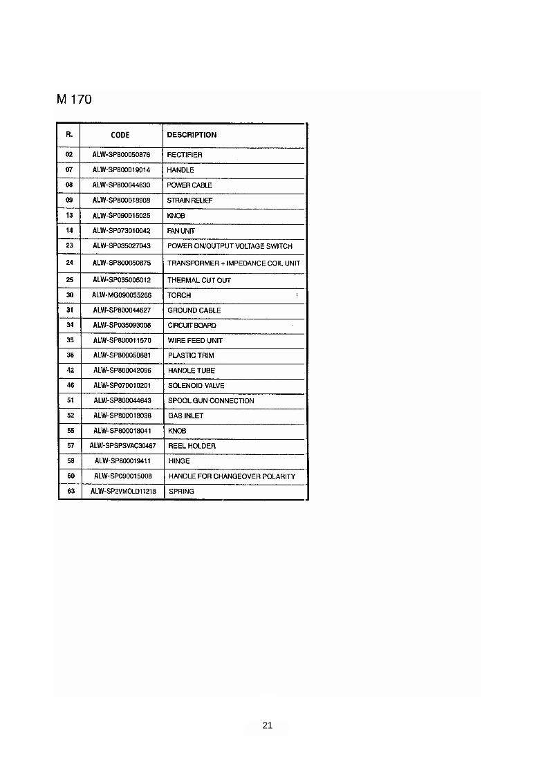
21
CODE

22
10. M 130 – M 170 COMMON SPARE PARTS LIST
CODE
CODE

23
11. MG 140 SPARE PARTS LIST